EP2305201B1 - Hospital bed caster control system - Google Patents
Hospital bed caster control system Download PDFInfo
- Publication number
- EP2305201B1 EP2305201B1 EP10189297A EP10189297A EP2305201B1 EP 2305201 B1 EP2305201 B1 EP 2305201B1 EP 10189297 A EP10189297 A EP 10189297A EP 10189297 A EP10189297 A EP 10189297A EP 2305201 B1 EP2305201 B1 EP 2305201B1
- Authority
- EP
- European Patent Office
- Prior art keywords
- brake
- shaft
- steer
- caster
- pedal
- Prior art date
- Legal status (The legal status is an assumption and is not a legal conclusion. Google has not performed a legal analysis and makes no representation as to the accuracy of the status listed.)
- Active
Links
- 230000007935 neutral effect Effects 0.000 claims description 70
- 230000007246 mechanism Effects 0.000 claims description 14
- 230000008878 coupling Effects 0.000 claims description 5
- 238000010168 coupling process Methods 0.000 claims description 5
- 238000005859 coupling reaction Methods 0.000 claims description 5
- 230000006835 compression Effects 0.000 description 7
- 238000007906 compression Methods 0.000 description 7
- 230000000994 depressogenic effect Effects 0.000 description 4
- 230000000903 blocking effect Effects 0.000 description 2
- 230000000881 depressing effect Effects 0.000 description 2
- 229910000831 Steel Inorganic materials 0.000 description 1
- XAGFODPZIPBFFR-UHFFFAOYSA-N aluminium Chemical compound [Al] XAGFODPZIPBFFR-UHFFFAOYSA-N 0.000 description 1
- 229910052782 aluminium Inorganic materials 0.000 description 1
- 230000001419 dependent effect Effects 0.000 description 1
- 239000003562 lightweight material Substances 0.000 description 1
- 238000005096 rolling process Methods 0.000 description 1
- 239000010959 steel Substances 0.000 description 1
Images


Classifications
-
- A—HUMAN NECESSITIES
- A61—MEDICAL OR VETERINARY SCIENCE; HYGIENE
- A61G—TRANSPORT, PERSONAL CONVEYANCES, OR ACCOMMODATION SPECIALLY ADAPTED FOR PATIENTS OR DISABLED PERSONS; OPERATING TABLES OR CHAIRS; CHAIRS FOR DENTISTRY; FUNERAL DEVICES
- A61G13/00—Operating tables; Auxiliary appliances therefor
- A61G13/0009—Obstetrical tables or delivery beds
-
- A—HUMAN NECESSITIES
- A61—MEDICAL OR VETERINARY SCIENCE; HYGIENE
- A61G—TRANSPORT, PERSONAL CONVEYANCES, OR ACCOMMODATION SPECIALLY ADAPTED FOR PATIENTS OR DISABLED PERSONS; OPERATING TABLES OR CHAIRS; CHAIRS FOR DENTISTRY; FUNERAL DEVICES
- A61G7/00—Beds specially adapted for nursing; Devices for lifting patients or disabled persons
- A61G7/002—Beds specially adapted for nursing; Devices for lifting patients or disabled persons having adjustable mattress frame
- A61G7/015—Beds specially adapted for nursing; Devices for lifting patients or disabled persons having adjustable mattress frame divided into different adjustable sections, e.g. for Gatch position
-
- A—HUMAN NECESSITIES
- A61—MEDICAL OR VETERINARY SCIENCE; HYGIENE
- A61G—TRANSPORT, PERSONAL CONVEYANCES, OR ACCOMMODATION SPECIALLY ADAPTED FOR PATIENTS OR DISABLED PERSONS; OPERATING TABLES OR CHAIRS; CHAIRS FOR DENTISTRY; FUNERAL DEVICES
- A61G7/00—Beds specially adapted for nursing; Devices for lifting patients or disabled persons
- A61G7/05—Parts, details or accessories of beds
- A61G7/0528—Steering or braking devices for castor wheels
-
- A—HUMAN NECESSITIES
- A61—MEDICAL OR VETERINARY SCIENCE; HYGIENE
- A61G—TRANSPORT, PERSONAL CONVEYANCES, OR ACCOMMODATION SPECIALLY ADAPTED FOR PATIENTS OR DISABLED PERSONS; OPERATING TABLES OR CHAIRS; CHAIRS FOR DENTISTRY; FUNERAL DEVICES
- A61G7/00—Beds specially adapted for nursing; Devices for lifting patients or disabled persons
- A61G7/05—Parts, details or accessories of beds
- A61G7/065—Rests specially adapted therefor
- A61G7/075—Rests specially adapted therefor for the limbs
- A61G7/0755—Rests specially adapted therefor for the limbs for the legs or feet
-
- Y—GENERAL TAGGING OF NEW TECHNOLOGICAL DEVELOPMENTS; GENERAL TAGGING OF CROSS-SECTIONAL TECHNOLOGIES SPANNING OVER SEVERAL SECTIONS OF THE IPC; TECHNICAL SUBJECTS COVERED BY FORMER USPC CROSS-REFERENCE ART COLLECTIONS [XRACs] AND DIGESTS
- Y10—TECHNICAL SUBJECTS COVERED BY FORMER USPC
- Y10T—TECHNICAL SUBJECTS COVERED BY FORMER US CLASSIFICATION
- Y10T74/00—Machine element or mechanism
- Y10T74/21—Elements
- Y10T74/2101—Cams
Definitions
- the present disclosure relates generally to a patient support apparatus, such as a hospital bed, having casters. More particularly, the present disclosure relates to an apparatus for controlling the brakes which engage the caster wheels supporting the patient support apparatus.
- Hospital beds are provided with casters mounted around the base for rolling the bed from place to place. At least one of the casters, and usually two, have at least two operating modes, namely, neutral and brake modes. Also, one of the casters has all three operating modes, namely, neutral, brake and steer modes. In the neutral mode, the caster wheel is free to swivel and rotate. In the brake mode, a brake pad is pressed against the surface of the caster wheel to prevent it from rotating and swiveling. In the steer mode, the caster wheel is locked against swiveling movement, but is free to rotate.
- the caster wheel is aligned parallel to a longitudinal dimension of the bed so that the bed can be pushed straight down a hallway without the bed drifting to one side or the other.
- An illustrative caster braking system is disclosed in U.S. Patent No. 5,377,372 .
- the present invention comprises an apparatus or a system that has one or more of the following features or combinations thereof.
- a patient support apparatus may comprise a base having a first side, a second side, a head end, and a foot end, a head end caster and a foot end caster coupled to the base on the first side near the respective head and foot ends, and a head end link and a foot end link located on the first side and operably associated with the respective head and foot end casters on the first side.
- the head and foot end links on the first side may be arranged to move longitudinally in opposite directions to brake the respective head and foot end casters on the first side.
- the apparatus may further include a shaft pivotably mounted to the base and a linkage coupling the shaft to the head and foot end links.
- the shaft may carry a pedal lever having a brake pedal. Depression of the brake pedal may cause the linkage to brake the two casters.
- the apparatus may include a pin secured to the shaft and a rotational stop secured to the base. The pin may engage the rotational stop to limit the rotation of the shaft in a braking direction in response to the depression of the brake pedal.
- the casters may each have a neutral mode and a brake mode.
- the pedal lever may include brake and steer pedals on the opposite sides thereof.
- the pedal lever may be disposed in a generally horizontal position when the two casters are in their respective neutral modes. Depression of the brake pedal beyond its generally horizontal position may cause the linkage to position the two casters in their respective brake modes.
- the steer pedal When the brake pedal is depressed beyond its generally horizontal position, the steer pedal may be used to return the brake pedal to its horizontal position to, in turn, position the two casters in their respective neutral modes.
- one of the two casters may be a brake-steer caster having neutral, brake and steer modes and the other of the two casters may be a brake caster having neutral and brake modes. Depression of the brake pedal beyond its generally horizontal position may cause the linkage to position the two casters in their respective brake modes, and depression of the steer pedal beyond its generally horizontal position may cause the linkage to position the brake-steer caster in the steer mode while allowing the brake caster to remain in the neutral mode.
- the apparatus may include a pin secured to the shaft and first and second rotational stops secured to the base.
- the pin may engage the first rotational stop to limit the rotation of the shaft in a braking direction in response to the depression of the brake pedal and the pin may engage the second rotational stop to limit the rotation of the shaft in a steering direction in response to the depression of the steer pedal.
- the base may have a first longitudinal rail on the first side, a second longitudinal rail on the second side and a cross beam interconnecting the two rails.
- the two links on the first side may be located within an interior region of the first rail, and the shaft may be located within an interior region of the cross beam.
- the linkage may include a cam mounted on the shaft for rotation therewith and head and foot end cam plates configured to operatively engage the cam.
- the cam and the cam plates may be located within the interior region of the first rail.
- the head and foot end cam plates may be coupled to the respective head and foot end links so that depression of the brake pedal may cause the cam to move the two cam plates in opposite directions to, in turn, move the two links in opposite directions to brake the two casters.
- the linkage may include a head end rocker arm pivotally coupled to the first rail near the head end and a foot end rocker arm pivotally coupled to the first rail near the foot end.
- a first end of the head end rocker arm may be adapted to actuate the head end caster.
- a second end of the head end rocker arm may be coupled to a first end of the head end link.
- a second end of the head end link may be coupled to the head end cam plate.
- a first end of the foot end rocker arm may be adapted to actuate the foot end caster.
- a second end of the foot end rocker arm may be coupled to a first end of the foot end link.
- a second end of the foot end link may be coupled to the foot end cam plate.
- the linkage may include a detent mechanism operable to resist the rotation of the shaft when the shaft is in angular positions that correspond to the neutral, brake and steer modes of the brake-steer caster.
- the detent mechanism may include a block coupled to the base and having a bore to rotatably support the shaft, a plunger slidably mounted in the block and biased forward so as to project into the bore, and a plurality of recesses around the circumference of the shaft. Each of the recesses may correspond to one of the neutral, brake and steer modes of the brake-steer caster.
- an illustrative birthing bed 20 includes a base frame 22 supported on casters 72, 74, 82, 84, an intermediate frame 24 supported above the base frame 22 by a parallelogram linkage 26, head, seat and foot deck sections 28, 30, 32 supported by the intermediate frame 24, an upper mattress 34 supported on the head and seat deck sections 28, 30, a leg support mattress 36 supported on the foot deck section 32, and a pair of side rails 38, 40 mounted on opposite sides of the head deck section. 28.
- the head and seat deck sections 28, 30 are articulatable relative to the intermediate frame 24.
- the foot deck section 32 is releasably secured to a yoke 38 that is, in turn, supported by the intermediate frame 24.
- the yoke 38 moves vertically as depicted by arrow 40 in Fig. 1 to adjust to a plurality of positions including positions in which the foot deck section 32 is vertically spaced from the seat deck section 30. This allows a caregiver to adjust the birthing bed 20 to a plurality of positions during labor and delivery.
- the upper mattress 34 has a v-shaped cavity 42 along the edge of the upper mattress 34 adjacent the foot deck section 32.
- the leg support mattress 36 has a protrusion 44 that is configured to be received in the cavity 42 to form a continuous support surface for a patient when the foot deck section 32 is vertically aligned with the seat deck section 30.
- the birthing bed 20 also comprises two articulatable foot supports 46 and 48. Foot support 46 is positioned to support a patient's left foot when in use while foot support 48 is positioned to support a patient's right foot when in use. An illustrative bed of this type is described in detail in U.S. Patent Application (7175-200142 ). Serial No. ______ , entitled “Stowing Birthing Bed Foot Section,” and filed concurrently herewith, which is hereby incorporated by reference herein.
- the base frame 22 has a cross beam 50 interconnecting a pair of longitudinal rails 56, 58, a head end 62, a foot end 64, a left side 66, a right side 68, a longitudinal axis 70 ( Fig. 4 ), and a longitudinal axis 76 ( Fig. 4 ).
- the cross beam 50 is a primary structural element tying the longitudinal rails 56, 58 together to form the base frame 22.
- the base frame 22 includes corner brackets or gussets 52 interconnecting the cross beam 50 with the longitudinal rails 56, 58.
- the longitudinal rails 56, 58 are flared outwardly toward the foot end 64 as shown in Figs. 2-4 .
- the cross beam 50 and the longitudinal rails 56, 58 are in the form of extruded tubular members having a generally rectangular cross section, and are made from rigid high strength, light weight materials, such as steel or aluminum.
- each of the casters 72, 74, 82, 84 is mounted within a socket 54 at each end 62, 64 of each rail 56, 58.
- Each socket 54 is covered by an end cap 60 to shield internal mechanisms.
- the phrase “head end 62" will be used to denote the end of any referred-to object that is positioned to lie nearest the head end 62
- the phrase “foot end 64” will be used to denote the end of any referred-to object that is positioned to lie nearest the foot end 64
- the phrase “left side 66” will be used to denote the side of any referred-to object that is positioned to lie nearest the left side 66
- the phrase “right side 68” will be used to denote the side of any referred-to object that is positioned to lie nearest the right side 68.
- the words “inwardly” and “outwardly” will refer to directions toward and away from, respectively, the geometric center of any referred-to object, such as the base frame, to which the reference is made.
- the casters 72, 74, 82, 84 have a plurality of operating modes.
- the caster 74 which is located near the foot end 64 on the left side 66 of the base frame 22, is a plunger-type caster having neutral, brake and steer modes (shown respectively in Figs. 14-16 ), while the three remaining casters 72, 82, 84 are plunger-type casters having only neutral and brake modes.
- neutral-brake-steer caster interchangeably with the term "brake-steer” caster, as well as to use the term “neutral-brake” caster interchangeably with the term “brake” caster.
- the caster 74 which is located near the foot end 64 on the left side 66 of the base frame 22 is a brake-steer caster, while the remaining three casters 72, 82, 84 are brake casters.
- the bed 20 could be provided with a different combination of brake casters, brake-steer casters, and conventional casters (without either the brake mode or the steer mode).
- the bed 20 may very well be provided with one brake-steer caster near the foot end 64 on the left side 66, one brake caster near the head end 62 on the right side 68, and two conventional casters.
- the bed 20 includes a brake-steer linkage 100, some components of which are housed within the tubular base frame 22.
- the brake-steer linkage 100 is operable to selectively position the brake-steer caster 74 in the neutral, brake and steer modes, and the three brake casters 72, 82, 84 in the neutral and brake modes.
- the linkage 100 is symmetrical on the left and right sides 66, 68 of the bed 20 as shown in Fig. 3 .
- the portion 96 of the linkage 100 on the left side 66 controls the casters 72, 74 on the left side 66, while the portion 98 of the linkage 100 on the right side 68 controls the casters 82, 84 on the right side 68.
- the linkage 100 comprises a two-piece shaft 104 ( Fig. 4 ) made up of shaft halves 106, 108, which extend toward the left and right sides 66, 68, respectively.
- the innermost ends of the shaft halves 106, 108 are coupled to a collar 358 ( Figs. 12-13 ).
- An outer end of each shaft half 106, 108 is rotatably supported in a bracket 110 ( Figs. 3-4 ).
- each shaft half 106, 108 includes a cam 112 (shown in Figs. 9-11 ) mounted thereon for rotation therewith.
- a pedal lever 126, 128 is connected to the outermost end of each shaft half 106, 108.
- the two shaft halves 106, 108, the two brackets 110 supporting the respective shaft halves 106, 108 and the two cams 112 mounted on the respective shaft halves 106, 108 are all mounted within the tubular cross beam 50.
- the pedal lever 126 on the left side 66 of the bed 20 includes a steer pedal 122 adjacent the head end 62 and a brake pedal 124 adjacent the foot end 64.
- the pedal lever 128 on the right side 68 of the bed 20 includes a steer pedal 132 adjacent the head end 62 and a brake pedal 134 adjacent the foot end 64.
- Both pedal levers 126, 128 have a generally horizontal position when all four casters 72, 74, 82, 84 are in their respective neutral modes.
- Downward actuation of either brake pedal 124, 134 beyond the generally horizontal position of the associated pedal lever 126, 128 causes the linkage 100 to position all four casters 72, 74, 82, 84 in their respective brake modes.
- either one of the steer pedals 122, 132 may be used to return the pedal levers 126, 128 to their respective horizontal positions to, in turn, position all four casters 72, 74, 82, 84 in their respective neutral modes.
- either one of the brake pedals 124, 134 may be used to return the pedal levers 126, 128 to their respective horizontal positions to, in turn, position all four casters 72, 74, 82, 84 in their respective neutral modes.
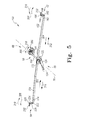
- Figs. 5-11 show the left hand portion 96 of the brake-steer linkage 100.
- the right hand portion 98 of the brake-steer linkage 100 is a mirror image of the left hand portion 96.
- the linkage 96 includes head and foot end links 152, 154 extending toward the respective head and foot ends 62, 64 of the base frame 22.
- the head and foot end links 152, 154 on the left side 66 of the bed 20 are mounted within the tubular longitudinal rail 56 on the left side 66 of the bed 20.
- the head and foot end links 152, 154 on the right side 68 of the bed 20 are mounted within the tubular longitudinal rail 58 on the right side 68 of the bed 20.
- the foot end links 154 flare outwardly toward the foot end 64 of the base frame 22 in the same manner as the longitudinal rails 56, 58 flare outwardly toward the foot end 64 of the base frame 22.
- a foot end 164 of the head end link 152 is connected to a head end cam plate 182 with suitable fasteners 180, such as screws, rivets, etc.
- Fig. 9 which is a view from the right side 68 of the base frame 22, the head end cam plate 182 is located inboard of a foot end cam plate 184.
- the head end cam plate 182 includes a cutout 190 therein for receiving the cam 112 mounted on the shaft half 106.
- a head end 162 of the head end link 152 on the left side 66 of the bed 20 has pivotally connected thereto at 192 a proximal end 194 of a rocker arm 196 (similar to the rocker arm 226 in Figs. 14-16 ).
- the rocker arm 196 is pivoted at 198 to the longitudinal rail 56 near the head end 62 of the rail 56.
- An adjusting screw (similar to the adjusting screw 230 in Figs. 14-16 ) is threaded into a distal end 202 of the rocker arm 196 for contacting an adjusting screw of a plunger of the associated brake caster 72 (similar to the plunger 236 of the brake-steer caster 74 in Figs. 14-16 ).
- the plunger of the brake caster 72 is spring loaded upwardly with a compression spring (similar to the compression spring 238 in Figs. 14-16 ).
- a head end 172 of the foot end link 154 is connected to the foot end cam plate 184 with suitable fasteners 180, such as screws, rivets, etc.
- the foot end cam plate 184 is located outboard of the head end cam plate 182.
- the cam plate 184 includes a cutout 220 therein for receiving the cam 112 mounted on the shaft half 106.
- a foot end 174 of the foot end link 154 has pivotally connected thereto at 222 a proximal end 224 of a rocker arm 226.
- the rocker arm 226 is pivoted at 228 to the longitudinal rail 56 near the foot end 64 of the rail 56.
- An adjusting screw 230 is threaded into a distal end 232 of the rocker arm 226 for contacting an adjusting screw 234 of a plunger 236 of the associated brake-steer caster 74.
- the brake-steer caster 74 includes a plunger housing 240 and a wheel yoke 242 mounted for swiveling movement with respect to the plunger housing 240 via a bearing 244.
- the plunger housing 240 is, in turn, received in the socket 54 mounted to the foot end 64 of the longitudinal rail 56.
- the plunger 236 is spring loaded upwardly by a compression spring 238.
- On the lower end of the plunger 236 is a downwardly facing bevel gear 246. In the brake mode, the downwardly facing bevel gear 246 is configured to engage an upwardly facing tooth 248 provided on a brake pad lever arm 250 as shown in Fig. 15 .
- the brake pad lever arm 250 is pivoted to the wheel yoke 242 at 252.
- a brake pad 254 is mounted on the underside of the brake pad lever arm 250.
- the brake-steer caster 74 With the plunger 236 in the position shown in Fig. 14 , the brake-steer caster 74 is said to be in its neutral mode which means that the caster yoke 242 may swivel freely with respect to the plunger housing 240 and the caster wheel 256 may rotate freely about its axis 258. With the plunger 236 in the position shown in Fig. 15 , the brake-steer caster 74 is said to be in its brake mode which means that the caster yoke 242 is prevented from swiveling with respect to the plunger housing 240 and the caster wheel 256 is prevented from rotating about its axis 258. As shown in Fig. 15 , in the brake mode, the downwardly facing bevel gear 246 engages the upwardly facing tooth 248 and, in addition, the brake pad 254 is pressed against the caster wheel 256.
- the brake-steer caster 74 is said to be in its steer mode which means that the caster yoke 242 is prevented from swiveling with respect to the plunger housing 240, but is aligned with the longitudinal axis 70 of the bed 20 to allow a caregiver to push the bed 20 in a straight line down a hallway without the bed 20 drifting to either side.
- the caster wheel 256 is free to rotate about its axis 258.
- a rib 260 on an upperside of the bevel gear 246 is received in a downwardly facing slot 262 in a plate 264 secured to the yoke 242.
- the brake-steer caster 74 is of the type manufactured by Tente Casters, Inc., Hebron, KY 41048, having a part number 2444 UAP 150 R05.
- the remaining three casters 72, 82, 84 are brake casters.
- the brake casters 72, 82, 84 are similar to the brake-steer caster 74 with one difference.
- the brake casters 72, 82, 84 do not have a steer mode.
- the three brake casters 72, 82, 84 are moved into and out of their respective neutral and brake modes in the same manner as the brake-steer caster 74 is moved into and out of its neutral and brake modes.
- the plunger of a brake caster 72, 82, 84 is in its upwardmost position (in the manner shown in Fig. 16 ), the caster wheel yoke is still free to swivel with respect to the plunger housing.
- the brake casters 72, 82, 84 do not have a plate with a slot therein (similar to the plate 264 with the slot 262 in Fig. 16 ) in which to capture a rib on an upperside of a bevel gear (similar to the rib 260 on the upperside the bevel gear 246 in Fig. 16 ) to block the swiveling movement of the brake casters 72, 82, 84.
- the three brake casters 72, 82, 84 are of the type manufactured by Tente Casters, Inc., Hebron, KY 41048, having a part number 2446 UAP 150 R05.
- the cam 112 has a parallelogram-shaped flange 268 at one end, a circular central portion 270 that extends axially inwardly from the flange 268 and oppositely disposed top and bottom lobes 272, 274 that project radially outwardly from the central portion 270.
- the cutout 190 in the head end cam plate 182 has a generally trapezoidal configuration having a top edge 280, a bottom edge 282 and side edges 284.
- the top edge 280 of the cutout 190 has a downwardly facing notch 286 that is configured to receive the top lobe 272 ( Fig. 10 ) of the cam 112.
- the cutout 220 in the foot end cam plate 184 has a generally trapezoidal configuration having a top edge 290, a bottom edge 292 and side edges 294.
- the bottom edge 292 of the cutout 220 has an upwardly facing notch 296 that is configured to receive the bottom lobe 274 ( Fig. 11 ) of the cam 112.
- the shaft half 106 rotates in a counterclockwise direction indicated by arrow 300.
- the top lobe 272 of the cam 112 received in the downwardly facing notch 286 in the head end cam plate 182 pushes the head end cam plate 182 (coupled to the link 152) toward the foot end 64 in a direction indicated by arrow 304 and the bottom lobe 274 of the cam 112 received in the upwardly facing notch 296 in the foot end cam plate 184 pushes the foot end cam plate 184 (coupled to the link 154) toward the head end 62 in a direction indicated by arrow 302.
- the head and foot end links 152, 154 coupled to the head and foot end cam plates 182, 184 are pulled inwardly in longitudinal directions 304, 302, respectively, relative to a transverse axis 76 ( Fig. 4 ) of the base frame 22.
- the linkage 96 includes a guide plate 320 ( Fig. 9 ) having an outwardly extending lip 322. The top edges of the cam plates 182, 184 are guided by the downwardly facing surface of the lip 322 as the cam plates 182, 184 move inwardly in directions 304, 302.
- the shaft half 106 rotates in a clockwise, direction indicated by arrow 310.
- the top lobe 272 of the cam 112 received in the downwardly facing notch 286 in the head end cam plate 182 pushes the head end cam plate 182 (coupled to the link 152) toward the head end 62 in a direction indicated by arrow 312 and the bottom lobe 274 of the cam 112 received in the upwardly facing notch 296 in the foot end cam plate 184 pushes the foot end cam plate 184 (coupled to the link 154) toward the foot end 64 in a direction indicated by arrow 314.
- the rib 260 on the upperside of the bevel gear 246 engages the downwardly facing slot 262 of the yoke 242 to block the swiveling movement of the foot end brake-steer caster 74, but not its rotation.
- the brake-steer linkage 100 includes a pair of links 152, 154 extending toward the head and foot ends 62, 64 of the base frame 22, a cam 112 having top and bottom lobes 272, 274 mounted on the shaft half 108 for rotation therewith, a head end cam plate 182 having a cutout 190 for receiving the cam 112, a foot end cam plate 184 having a cutout 220 for receiving the cam 112, and rocker arms 196, 226 coupled to the respective links 152, 154 on the right side 68 of the base frame 22.
- the three brake casters 72, 82, 84 are moved into and out of their respective neutral and brake modes in the same manner as the brake-steer caster 74 is moved into and out of its neutral and brake modes.
- the plunger of a brake caster 72, 82, 84 is in its upwardmost position (similar to the position shown in Fig. 16 )
- the caster wheel yoke of the associated brake caster 72, 82, 84 is still free to swivel with respect to the plunger housing. This is so because the brake casters 72, 82, 84 do not have a plate with a slot therein (similar to the plate 264 with the slot 262 therein as shown in Fig.
- Both pedal levers 126, 128 have a generally horizontal position when all four casters 72, 74, 82, 84 are in their respective neutral modes. Downward actuation of either brake pedal 124, 134 beyond the generally horizontal position of the associated pedal lever 126, 128 causes the linkage 100 to position all four casters 72, 74, 82, 84 in their respective brake modes. On the other hand, downward actuation of either steer pedal 122, 132 beyond the generally horizontal position of the associated pedal lever 126, 128 causes the linkage 100 to position the brake-steer caster 74 in the steer mode, while allowing the remaining three brake casters 72, 82, 84 to remain in the neutral mode.
- either one of the steer pedals 122, 132 may be used to return the pedal levers 126, 128 to their respective horizontal positions to, in turn, position all four casters 72, 74, 82, 84 in their respective neutral modes.
- either one of the brake pedals 124, 134 may be used to return the pedal levers 126, 128 to their respective horizontal positions to, in turn, position all four casters 72, 74, 82, 84 in their respective neutral modes.
- the detent mechanism 350 for maintaining shaft 104 in the three respective angular positions which correspond the neutral, brake and steer modes of the brake-steer caster 74 and the neutral and brake modes of the three brake casters 72, 82, and 84.
- the detent mechanism 350 includes a mounting block 352 secured to an access plate 354.
- the access plate 354 is, in turn, removably mounted to the cross beam 50 from an underside of the cross beam 50 with suitable fasteners, such as screws.
- the mounting block 352 includes a bore 356 which rotatably supports a collar 358.
- the collar 358 has a bore 360 which receives the innermost ends of the two shaft halves 106, 108.
- the innermost ends of the shaft halves 106, 108 are secured to the collar 358 with pins (not shown) to rotatably couple the shaft halves 106, 108 to each other.
- the mounting block 352 further houses a longitudinally shifting plunger 362 which is spring loaded toward the collar 358 with a compression spring 364.
- the plunger 362 includes a plunger tip 366 which cooperates with three similarly shaped notches 368, 370, and 372 in the collar 358.
- the three notches 368, 370 and 372 corresponds to the neutral, brake and steer positions of the pedal levers 126, 128, which positions, in turn, correspond to the neutral, brake and steer modes of the brake-steer caster 74 and the neutral and brake modes of the brake casters 72, 82, 84.
- the centermost notch 368 corresponds to the neutral mode.
- the notch 370 corresponds to the brake mode.
- the notch 372 corresponds to the steer mode.
- the mounting block 352 includes a V-shaped notch 374 therein having ends 376, 378 which serve as stops for a stop pin 380 pressed into the collar 358 on the side of the collar 358 facing the V-shaped notch 374.
- one of the pedal levers 126, 128 will normally be positioned in a horizontal position thus placing the brake-steer caster 74, as well as the three brake casters 72, 82, 84, in their respective neutral modes, thereby allowing the casters 72, 74, 82, 84 to swivel freely relative to their respective housings (not shown) and allowing the caster wheels of the casters 72, 74, 82, 84 to rotate freely about their respective rotational axes.
- the pedal levers 126, 128 are maintained in the horizontal position by the compression spring 364 which forces the plunger tip 366 into the centermost notch 368 in the collar 358.
Description
- The present disclosure relates generally to a patient support apparatus, such as a hospital bed, having casters. More particularly, the present disclosure relates to an apparatus for controlling the brakes which engage the caster wheels supporting the patient support apparatus.
- Hospital beds are provided with casters mounted around the base for rolling the bed from place to place. At least one of the casters, and usually two, have at least two operating modes, namely, neutral and brake modes. Also, one of the casters has all three operating modes, namely, neutral, brake and steer modes. In the neutral mode, the caster wheel is free to swivel and rotate. In the brake mode, a brake pad is pressed against the surface of the caster wheel to prevent it from rotating and swiveling. In the steer mode, the caster wheel is locked against swiveling movement, but is free to rotate. In addition, in the steer mode, the caster wheel is aligned parallel to a longitudinal dimension of the bed so that the bed can be pushed straight down a hallway without the bed drifting to one side or the other. An illustrative caster braking system is disclosed in
U.S. Patent No. 5,377,372 . - The present invention comprises an apparatus or a system that has one or more of the following features or combinations thereof.
- A patient support apparatus may comprise a base having a first side, a second side, a head end, and a foot end, a head end caster and a foot end caster coupled to the base on the first side near the respective head and foot ends, and a head end link and a foot end link located on the first side and operably associated with the respective head and foot end casters on the first side. The head and foot end links on the first side may be arranged to move longitudinally in opposite directions to brake the respective head and foot end casters on the first side.
- The apparatus may further include a shaft pivotably mounted to the base and a linkage coupling the shaft to the head and foot end links. The shaft may carry a pedal lever having a brake pedal. Depression of the brake pedal may cause the linkage to brake the two casters. The apparatus may include a pin secured to the shaft and a rotational stop secured to the base. The pin may engage the rotational stop to limit the rotation of the shaft in a braking direction in response to the depression of the brake pedal.
- In some embodiments, the casters may each have a neutral mode and a brake mode. The pedal lever may include brake and steer pedals on the opposite sides thereof. The pedal lever may be disposed in a generally horizontal position when the two casters are in their respective neutral modes. Depression of the brake pedal beyond its generally horizontal position may cause the linkage to position the two casters in their respective brake modes. When the brake pedal is depressed beyond its generally horizontal position, the steer pedal may be used to return the brake pedal to its horizontal position to, in turn, position the two casters in their respective neutral modes.
- In some embodiments, one of the two casters may be a brake-steer caster having neutral, brake and steer modes and the other of the two casters may be a brake caster having neutral and brake modes. Depression of the brake pedal beyond its generally horizontal position may cause the linkage to position the two casters in their respective brake modes, and depression of the steer pedal beyond its generally horizontal position may cause the linkage to position the brake-steer caster in the steer mode while allowing the brake caster to remain in the neutral mode.
- The apparatus may include a pin secured to the shaft and first and second rotational stops secured to the base. The pin may engage the first rotational stop to limit the rotation of the shaft in a braking direction in response to the depression of the brake pedal and the pin may engage the second rotational stop to limit the rotation of the shaft in a steering direction in response to the depression of the steer pedal.
- The base may have a first longitudinal rail on the first side, a second longitudinal rail on the second side and a cross beam interconnecting the two rails. The two links on the first side may be located within an interior region of the first rail, and the shaft may be located within an interior region of the cross beam. In some embodiments, the linkage may include a cam mounted on the shaft for rotation therewith and head and foot end cam plates configured to operatively engage the cam. The cam and the cam plates may be located within the interior region of the first rail. The head and foot end cam plates may be coupled to the respective head and foot end links so that depression of the brake pedal may cause the cam to move the two cam plates in opposite directions to, in turn, move the two links in opposite directions to brake the two casters.
- The linkage may include a head end rocker arm pivotally coupled to the first rail near the head end and a foot end rocker arm pivotally coupled to the first rail near the foot end. A first end of the head end rocker arm may be adapted to actuate the head end caster. A second end of the head end rocker arm may be coupled to a first end of the head end link. A second end of the head end link may be coupled to the head end cam plate. A first end of the foot end rocker arm may be adapted to actuate the foot end caster. A second end of the foot end rocker arm may be coupled to a first end of the foot end link. A second end of the foot end link may be coupled to the foot end cam plate.
- In some embodiments, the linkage may include a detent mechanism operable to resist the rotation of the shaft when the shaft is in angular positions that correspond to the neutral, brake and steer modes of the brake-steer caster. The detent mechanism may include a block coupled to the base and having a bore to rotatably support the shaft, a plunger slidably mounted in the block and biased forward so as to project into the bore, and a plurality of recesses around the circumference of the shaft. Each of the recesses may correspond to one of the neutral, brake and steer modes of the brake-steer caster.
- The invention will now be described by way of example with reference to the accompanying drawings in which:
-
Fig. 1 is a perspective view of an illustrative birthing bed showing a base frame supported on casters which have a plurality of operating modes, an intermediate frame supported above the base by a parallelogram linkage, head, seat and foot deck sections supported by the intermediate frame, an upper mattress supported on the head and seat deck sections, a leg support mattress supported on the foot deck section, and a pair of side rails mounted on opposite sides of the head deck section; -
Fig. 2 is a perspective view, with portions omitted, of the base frame showing the base frame including a cross beam interconnecting a pair of longitudinally extending rails, a caster coupled to each end of each rail, and showing a brake-steer linkage coupled to the base frame and operable to selectively position the casters in one of the plurality of operating modes; -
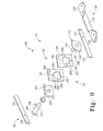
Fig. 3 is an exploded perspective view showing the base frame and the brake-steer linkage; -
Fig. 4 is a bottom view of the base frame; -
Fig. 5 is a perspective view of a portion of the brake-steer linkage on the left side of the bed showing a brake-steer shaft extending outwardly from a detent mechanism, a cam mounted on the brake-steer shaft, a brake-steer pedal coupled to the brake-steer shaft outboard of the cam, a head end cam plate coupled to a head end link extending toward a head end of the bed, a foot end cam plate coupled to a foot end link extending toward a foot end of the bed, and head and foot end rocker arms coupled to the respective head and foot end links; -
Fig. 6 is an enlarged perspective view showing the detent mechanism, the brake-steer shaft, the cam mounted on the brake-steer shaft, the brake-steer pedal outboard of the cam, the head end cam plate coupled to the head end link extending toward the head end, and the foot end cam plate coupled to the foot end link extending toward the foot end; -
Fig. 7 is an enlarged perspective view from the left side of the bed showing a portion of the brake-steer shaft, the cam mounted on the brake-steer shaft, the brake-steer pedal outboard of the cam, the head end cam plate coupled to the head end link, the foot end cam plate coupled to the foot end link, a bottom lobe of the cam received in an upwardly facing notch in the foot end cam plate; -
Fig. 8 is an enlarged perspective view similar toFig. 7 , but from a right side of the bed, showing a top lobe of the cam received in a downwardly facing notch in the head end cam plate; -
Fig. 9 is an exploded perspective view of the left hand portion of the brake-steer linkage; -
Fig. 10 is a side elevation view, with portions omitted, diagrammatically showing the head end cam plate coupled to the head end link extending toward the head end, and the cam having an upwardly extending lobe received in a downwardly facing notch in the head end cam plate; -
Fig. 11 is a side elevation view, with portions omitted, similar toFig. 10 , but diagrammatically showing the cam having a downwardly extending lobe received in an upwardly facing notch in the foot end cam plate; -
Fig. 12 is a perspective view of the detent mechanism; -
Fig. 13 is an exploded perspective view of the detent mechanism; -
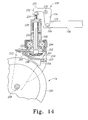
Fig. 14 is a side elevation view, in partial cross-section, of the brake-steer caster near the foot end and on the left side of the bed, with the brake-steer caster in a neutral mode; -
Fig. 15 is a view similar toFig. 14 , but with the brake-steer caster in a brake mode; and -
Fig. 16 is a view similar toFig. 14 , but with the brake-steer caster in a steer mode. - As shown in
Fig. 1 , anillustrative birthing bed 20 includes abase frame 22 supported oncasters intermediate frame 24 supported above thebase frame 22 by aparallelogram linkage 26, head, seat andfoot deck sections intermediate frame 24, anupper mattress 34 supported on the head andseat deck sections leg support mattress 36 supported on thefoot deck section 32, and a pair ofside rails seat deck sections intermediate frame 24. Thefoot deck section 32 is releasably secured to ayoke 38 that is, in turn, supported by theintermediate frame 24. Theyoke 38 moves vertically as depicted byarrow 40 inFig. 1 to adjust to a plurality of positions including positions in which thefoot deck section 32 is vertically spaced from theseat deck section 30. This allows a caregiver to adjust thebirthing bed 20 to a plurality of positions during labor and delivery. - The
upper mattress 34 has a v-shapedcavity 42 along the edge of theupper mattress 34 adjacent thefoot deck section 32. Theleg support mattress 36 has aprotrusion 44 that is configured to be received in thecavity 42 to form a continuous support surface for a patient when thefoot deck section 32 is vertically aligned with theseat deck section 30. Thebirthing bed 20 also comprises two articulatable foot supports 46 and 48.Foot support 46 is positioned to support a patient's left foot when in use whilefoot support 48 is positioned to support a patient's right foot when in use. An illustrative bed of this type is described in detail inU.S. Patent Application (7175-200142 ). Serial No. ______ , entitled "Stowing Birthing Bed Foot Section," and filed concurrently herewith, which is hereby incorporated by reference herein. - Referring to
Figs. 2-4 , thebase frame 22 has across beam 50 interconnecting a pair oflongitudinal rails head end 62, afoot end 64, aleft side 66, aright side 68, a longitudinal axis 70 (Fig. 4 ), and a longitudinal axis 76 (Fig. 4 ). Thecross beam 50 is a primary structural element tying thelongitudinal rails base frame 22. Thebase frame 22 includes corner brackets orgussets 52 interconnecting thecross beam 50 with thelongitudinal rails longitudinal rails foot end 64 as shown inFigs. 2-4 . In the illustrated embodiment, thecross beam 50 and thelongitudinal rails Fig. 3 , each of thecasters socket 54 at eachend rail socket 54 is covered by anend cap 60 to shield internal mechanisms. - As used in this description, the phrase "
head end 62" will be used to denote the end of any referred-to object that is positioned to lie nearest thehead end 62, and the phrase "foot end 64" will be used to denote the end of any referred-to object that is positioned to lie nearest thefoot end 64. Likewise, the phrase "left side 66" will be used to denote the side of any referred-to object that is positioned to lie nearest theleft side 66, and the phrase "right side 68" will be used to denote the side of any referred-to object that is positioned to lie nearest theright side 68. The words "inwardly" and "outwardly" will refer to directions toward and away from, respectively, the geometric center of any referred-to object, such as the base frame, to which the reference is made. - In the illustrated embodiment, the
casters caster 74, which is located near thefoot end 64 on theleft side 66 of thebase frame 22, is a plunger-type caster having neutral, brake and steer modes (shown respectively inFigs. 14-16 ), while the three remainingcasters caster 74, which is located near thefoot end 64 on theleft side 66 of thebase frame 22 is a brake-steer caster, while the remaining threecasters bed 20 could be provided with a different combination of brake casters, brake-steer casters, and conventional casters (without either the brake mode or the steer mode). For example, thebed 20 may very well be provided with one brake-steer caster near thefoot end 64 on theleft side 66, one brake caster near thehead end 62 on theright side 68, and two conventional casters. - As shown in
Figs. 3-4 , thebed 20 includes a brake-steer linkage 100, some components of which are housed within thetubular base frame 22. The brake-steer linkage 100 is operable to selectively position the brake-steer caster 74 in the neutral, brake and steer modes, and the threebrake casters linkage 100 is symmetrical on the left andright sides bed 20 as shown inFig. 3 . Theportion 96 of thelinkage 100 on theleft side 66 controls thecasters left side 66, while theportion 98 of thelinkage 100 on theright side 68 controls thecasters right side 68. - The
linkage 100 comprises a two-piece shaft 104 (Fig. 4 ) made up ofshaft halves right sides Figs. 12-13 ). An outer end of eachshaft half Figs. 3-4 ). Outboard of thebracket 110, eachshaft half Figs. 9-11 ) mounted thereon for rotation therewith. Apedal lever shaft half shaft halves brackets 110 supporting therespective shaft halves cams 112 mounted on therespective shaft halves tubular cross beam 50. - Referring to
Figs. 2-8 , thepedal lever 126 on theleft side 66 of thebed 20 includes asteer pedal 122 adjacent thehead end 62 and abrake pedal 124 adjacent thefoot end 64. Thepedal lever 128 on theright side 68 of thebed 20 includes asteer pedal 132 adjacent thehead end 62 and abrake pedal 134 adjacent thefoot end 64. Bothpedal levers casters brake pedal pedal lever linkage 100 to position all fourcasters steer pedal pedal lever linkage 100 to position the brake-steer caster 74 in the steer mode, while allowing the remaining threebrake casters - When the
brake pedals steer pedals casters steer pedals brake pedals casters -
Figs. 5-11 show theleft hand portion 96 of the brake-steer linkage 100. As shown inFig. 3 , theright hand portion 98 of the brake-steer linkage 100 is a mirror image of theleft hand portion 96. Thelinkage 96 includes head andfoot end links base frame 22. The head andfoot end links left side 66 of thebed 20 are mounted within the tubularlongitudinal rail 56 on theleft side 66 of thebed 20. Likewise, the head andfoot end links right side 68 of thebed 20 are mounted within the tubularlongitudinal rail 58 on theright side 68 of thebed 20. As shown inFig. 3 , thefoot end links 154 flare outwardly toward thefoot end 64 of thebase frame 22 in the same manner as thelongitudinal rails foot end 64 of thebase frame 22. As shown inFigs. 6-8 , afoot end 164 of thehead end link 152 is connected to a headend cam plate 182 withsuitable fasteners 180, such as screws, rivets, etc. As shown inFig. 9 , which is a view from theright side 68 of thebase frame 22, the headend cam plate 182 is located inboard of a footend cam plate 184. As shown inFig. 10 , the headend cam plate 182 includes acutout 190 therein for receiving thecam 112 mounted on theshaft half 106. - As shown in
Fig. 5 , ahead end 162 of thehead end link 152 on theleft side 66 of thebed 20 has pivotally connected thereto at 192 aproximal end 194 of a rocker arm 196 (similar to therocker arm 226 inFigs. 14-16 ). Therocker arm 196 is pivoted at 198 to thelongitudinal rail 56 near thehead end 62 of therail 56. An adjusting screw (similar to the adjustingscrew 230 inFigs. 14-16 ) is threaded into adistal end 202 of therocker arm 196 for contacting an adjusting screw of a plunger of the associated brake caster 72 (similar to theplunger 236 of the brake-steer caster 74 inFigs. 14-16 ). The plunger of thebrake caster 72 is spring loaded upwardly with a compression spring (similar to thecompression spring 238 inFigs. 14-16 ). - As shown in
Figs. 6-8 , ahead end 172 of thefoot end link 154 is connected to the footend cam plate 184 withsuitable fasteners 180, such as screws, rivets, etc. As shown inFig. 9 , the footend cam plate 184 is located outboard of the headend cam plate 182. As shown inFig. 11 , thecam plate 184 includes acutout 220 therein for receiving thecam 112 mounted on theshaft half 106. As shown inFigs. 5 and14-16 , afoot end 174 of thefoot end link 154 has pivotally connected thereto at 222 aproximal end 224 of arocker arm 226. Therocker arm 226 is pivoted at 228 to thelongitudinal rail 56 near thefoot end 64 of therail 56. An adjustingscrew 230 is threaded into adistal end 232 of therocker arm 226 for contacting an adjustingscrew 234 of aplunger 236 of the associated brake-steer caster 74. - As shown in
Figs. 14-16 , the brake-steer caster 74 includes aplunger housing 240 and awheel yoke 242 mounted for swiveling movement with respect to theplunger housing 240 via abearing 244. As shown inFig. 3 , theplunger housing 240 is, in turn, received in thesocket 54 mounted to thefoot end 64 of thelongitudinal rail 56. Theplunger 236 is spring loaded upwardly by acompression spring 238. On the lower end of theplunger 236 is a downwardly facingbevel gear 246. In the brake mode, the downwardly facingbevel gear 246 is configured to engage an upwardly facingtooth 248 provided on a brakepad lever arm 250 as shown inFig. 15 . The brakepad lever arm 250 is pivoted to thewheel yoke 242 at 252. Abrake pad 254 is mounted on the underside of the brakepad lever arm 250. - With the
plunger 236 in the position shown inFig. 14 , the brake-steer caster 74 is said to be in its neutral mode which means that thecaster yoke 242 may swivel freely with respect to theplunger housing 240 and thecaster wheel 256 may rotate freely about itsaxis 258. With theplunger 236 in the position shown inFig. 15 , the brake-steer caster 74 is said to be in its brake mode which means that thecaster yoke 242 is prevented from swiveling with respect to theplunger housing 240 and thecaster wheel 256 is prevented from rotating about itsaxis 258. As shown inFig. 15 , in the brake mode, the downwardly facingbevel gear 246 engages the upwardly facingtooth 248 and, in addition, thebrake pad 254 is pressed against thecaster wheel 256. - With the
plunger 236 in the position shown inFig. 16 , the brake-steer caster 74 is said to be in its steer mode which means that thecaster yoke 242 is prevented from swiveling with respect to theplunger housing 240, but is aligned with thelongitudinal axis 70 of thebed 20 to allow a caregiver to push thebed 20 in a straight line down a hallway without thebed 20 drifting to either side. In addition, in the steer mode, thecaster wheel 256 is free to rotate about itsaxis 258. In the steer mode, as shown inFig. 16 , arib 260 on an upperside of thebevel gear 246 is received in a downwardly facingslot 262 in aplate 264 secured to theyoke 242. In the illustrated embodiment, the brake-steer caster 74 is of the type manufactured by Tente Casters, Inc., Hebron, KY 41048, having a part number 2444 UAP 150 R05. - The remaining three
casters steer caster 74 with one difference. The brake casters 72, 82, 84 do not have a steer mode. The threebrake casters steer caster 74 is moved into and out of its neutral and brake modes. When the plunger of abrake caster Fig. 16 ), the caster wheel yoke is still free to swivel with respect to the plunger housing. This is so because thebrake casters plate 264 with theslot 262 inFig. 16 ) in which to capture a rib on an upperside of a bevel gear (similar to therib 260 on the upperside thebevel gear 246 inFig. 16 ) to block the swiveling movement of thebrake casters brake casters - As shown in
Figs. 9-11 , thecam 112 has a parallelogram-shapedflange 268 at one end, a circularcentral portion 270 that extends axially inwardly from theflange 268 and oppositely disposed top andbottom lobes central portion 270. As shown inFig. 9 , thecutout 190 in the headend cam plate 182 has a generally trapezoidal configuration having atop edge 280, abottom edge 282 and side edges 284. Thetop edge 280 of thecutout 190 has a downwardly facingnotch 286 that is configured to receive the top lobe 272 (Fig. 10 ) of thecam 112. Likewise, thecutout 220 in the footend cam plate 184 has a generally trapezoidal configuration having atop edge 290, abottom edge 292 and side edges 294. Thebottom edge 292 of thecutout 220 has an upwardly facingnotch 296 that is configured to receive the bottom lobe 274 (Fig. 11 ) of thecam 112. - Referring to
Figs. 5-11 , upon depressing thebrake pedal 124 downwardly, theshaft half 106 rotates in a counterclockwise direction indicated byarrow 300. When theshaft half 106 rotates in thecounterclockwise direction 300, thetop lobe 272 of thecam 112 received in the downwardly facingnotch 286 in the headend cam plate 182 pushes the head end cam plate 182 (coupled to the link 152) toward thefoot end 64 in a direction indicated byarrow 304 and thebottom lobe 274 of thecam 112 received in the upwardly facingnotch 296 in the footend cam plate 184 pushes the foot end cam plate 184 (coupled to the link 154) toward thehead end 62 in a direction indicated byarrow 302. Thus, when theshaft half 106 rotates in thecounterclockwise direction 300, the head andfoot end links end cam plates longitudinal directions Fig. 4 ) of thebase frame 22. Thelinkage 96 includes a guide plate 320 (Fig. 9 ) having an outwardly extendinglip 322. The top edges of thecam plates lip 322 as thecam plates directions - As shown in
Fig. 5 , when thehead end link 152 is pulled inwardly indirection 304, the rocker arm 196 (similar to therocker arm 226 inFig. 15 ) on theleft side 66 of thebase frame 22 near thehead end 62 rotates in a clockwise direction indicated byarrow 306. Rotation of the headend rocker arm 196 in theclockwise direction 306 forces the spring-loaded plunger (similar to theplunger 236 inFig. 15 ) of the headend brake caster 72 downwardly, thereby blocking the rotation of the caster wheel (similar to thecaster wheel 256 inFig. 15 ) about its axis and the swiveling movement of the caster wheel yoke (similar to thecaster wheel yoke 242 inFig. 15 ) about the plunger housing (similar to theplunger housing 240 inFig. 15 ). Likewise, as shown inFigs. 5 and15 , when thefoot end link 154 is pulled inwardly indirection 302, therocker arm 226 on theleft side 66 near thefoot end 64 rotates in a counterclockwise direction indicated byarrow 308. Rotation of the footend rocker arm 226 in thecounterclockwise direction 308 forces the spring-loadedplunger 236 of the foot end brake-steer caster 74 downwardly, thereby blocking the rotation and the swiveling movement of the foot end brake-steer caster 74. - On the other hand, as shown in
Figs. 5-11 , upon depressing thesteer pedal 122 downwardly, theshaft half 106 rotates in a clockwise, direction indicated byarrow 310. When theshaft half 106 rotates in theclockwise direction 310, thetop lobe 272 of thecam 112 received in the downwardly facingnotch 286 in the headend cam plate 182 pushes the head end cam plate 182 (coupled to the link 152) toward thehead end 62 in a direction indicated byarrow 312 and thebottom lobe 274 of thecam 112 received in the upwardly facingnotch 296 in the footend cam plate 184 pushes the foot end cam plate 184 (coupled to the link 154) toward thefoot end 64 in a direction indicated byarrow 314. Thus, when theshaft half 106 rotates in aclockwise direction 310, thelinks outer plates longitudinal directions Fig. 4 ) of thebase frame 22. The top edges of thecam plates lip 322 as thecam plates directions - As shown in
Fig. 5 , when thehead end link 152 is pushed outwardly indirection 312, therocker arm 196 on theleft side 66 of thebase frame 22 near thehead end 62 rotates in a counterclockwise direction indicated byarrow 316. Rotation of the headend rocker arm 196 in thecounterclockwise direction 316 allows the spring-loaded plunger (similar to theplunger 236 shown inFig. 16 ) of the headend brake caster 72 to move upwardly. The upward movement of the plunger of the headend brake caster 72 to a position that corresponds to the position of theplunger 236 inFig. 16 allows the caster wheel (similar to thecaster wheel 256 shown inFig. 16 ) to rotate freely about its axis and allows thebrake caster 72 to swivel freely. As shown inFigs. 5 and16 , when thefoot end link 154 is pushed outwardly indirection 314, therocker arm 226 on theleft side 66 near thefoot end 64 rotates in a clockwise direction indicated byarrow 318. Rotation of the footend rocker arm 226 in theclockwise direction 318 allows the spring-loadedplunger 236 of the foot end brake-steer caster 74 to move upwardly. As a result, therib 260 on the upperside of thebevel gear 246 engages the downwardly facingslot 262 of theyoke 242 to block the swiveling movement of the foot end brake-steer caster 74, but not its rotation. - As shown in
Fig. 3 , on theright side 68 of thebase frame 22, the brake-steer linkage 100 includes a pair oflinks base frame 22, acam 112 having top andbottom lobes shaft half 108 for rotation therewith, a headend cam plate 182 having acutout 190 for receiving thecam 112, a footend cam plate 184 having acutout 220 for receiving thecam 112, androcker arms respective links right side 68 of thebase frame 22. When thebrake pedal 134 on theright side 68 is depressed, the head andfoot end casters brake caster 72 on theleft side 66. When thesteer pedal 132 on theright side 68 is depressed, the head andfoot end casters brake caster 72 on theleft side 66. - The three
brake casters steer caster 74 is moved into and out of its neutral and brake modes. However, when the plunger of abrake caster Fig. 16 ), the caster wheel yoke of the associatedbrake caster brake casters plate 264 with theslot 262 therein as shown inFig. 16 ) in which to capture a rib on an upperside of a bevel gear (similar to therib 260 on the upperside thebevel gear 246 as shown inFig. 16 ) to block swiveling movement of thebrake casters - Both
pedal levers casters brake pedal pedal lever linkage 100 to position all fourcasters steer pedal pedal lever linkage 100 to position the brake-steer caster 74 in the steer mode, while allowing the remaining threebrake casters brake pedals steer pedals casters steer pedals brake pedals casters - Referring now to
Figs. 12-13 , there is illustrated adetent mechanism 350 for maintainingshaft 104 in the three respective angular positions which correspond the neutral, brake and steer modes of the brake-steer caster 74 and the neutral and brake modes of the threebrake casters detent mechanism 350 includes amounting block 352 secured to anaccess plate 354. Theaccess plate 354 is, in turn, removably mounted to thecross beam 50 from an underside of thecross beam 50 with suitable fasteners, such as screws. The mountingblock 352 includes abore 356 which rotatably supports acollar 358. Thecollar 358 has abore 360 which receives the innermost ends of the twoshaft halves collar 358 with pins (not shown) to rotatably couple the shaft halves 106, 108 to each other. - The mounting
block 352 further houses alongitudinally shifting plunger 362 which is spring loaded toward thecollar 358 with acompression spring 364. Theplunger 362 includes aplunger tip 366 which cooperates with three similarlyshaped notches collar 358. The threenotches steer caster 74 and the neutral and brake modes of thebrake casters steer caster 74 is moved from the neutral mode to the steer mode, thebrake casters centermost notch 368 corresponds to the neutral mode. Thenotch 370 corresponds to the brake mode. Thenotch 372 corresponds to the steer mode. - The mounting
block 352 includes a V-shapednotch 374 therein having ends 376, 378 which serve as stops for astop pin 380 pressed into thecollar 358 on the side of thecollar 358 facing the V-shapednotch 374. In use, one of the pedal levers 126, 128 will normally be positioned in a horizontal position thus placing the brake-steer caster 74, as well as the threebrake casters casters casters compression spring 364 which forces theplunger tip 366 into thecentermost notch 368 in thecollar 358. - Pressing one of the
steer pedals rocker arms caster 74 is a brake-steer caster, thecaster 74 is prevented from swiveling while thebrake casters compression spring 364 which forces theplunger tip 366 into thenotch 372 in thecollar 358. Over travel of the pedal levers 666, 668, the shaft halves 106, 108, and thecollar 358 is prevented by thestop pin 380 received in the V-shapednotch 374 in themounting block 352. - To take the
bed 20 out of its steer mode and to activate the brake mode of thecasters bed 20, one of thebrake pedals rocker arms casters compression spring 364 which forces theplunger tip 366 into thenotch 370 in thecollar 358. Over travel of the pedal levers 126, 128, the shaft halves 106, 108, and thecollar 358 is prevented by thestop pin 380 received in the V-shapednotch 374 in theblock 352. - Embodiments of the invention can be described with reference to the following numbered clauses, with preferred features laid out in the dependent clauses:
- 1. A patient support apparatus comprising:
- a base having a first side, a second side, a head end, and a foot end,
- a head end caster and a foot end caster coupled to the base on the first side near the respective head and foot ends, and
- a head end link and a foot end link located on the first side and operably associated with the respective head and foot end casters on the first side, the head and foot end links on the first side moving longitudinally in opposite directions to brake the respective head and foot end casters on the first side.
- 2. The apparatus of clause 1, further comprising a shaft pivotably mounted to the base and carrying a brake pedal and a linkage coupling the shaft to the head and foot end links, wherein downward actuation of the brake pedal causes the linkage to brake the two casters.
- 3. The apparatus of clause 2, further comprising a pin secured to the shaft and a rotational stop secured to the base, wherein the pin engages the rotational stop to limit the rotation of the shaft in a braking direction in response to the downward actuation of the brake pedal.
- 4. The apparatus of clause 1, further comprising a shaft pivotably mounted to the base and carrying a pedal lever and a linkage coupling the shaft to the head and foot end links, wherein each caster has a neutral mode and a brake mode, the pedal lever has brake and steer pedals on opposite sides of the shaft, the pedal lever has a generally horizontal position when the two casters are in their respective neutral modes, downward actuation of the brake pedal beyond the generally horizontal position causes the linkage to position the two casters in their respective brake modes, and downward actuation of the steer pedal beyond the generally horizontal position causes the linkage to position the two casters in their respective neutral modes.
- 5. The apparatus of clause 1, further comprising a shaft pivotably mounted to the base and carrying a pedal lever and a linkage coupling the shaft to the head and foot end links, wherein one of the two casters is a brake-steer caster having neutral, brake and steer modes and the other of the two casters is a brake caster having neutral and brake modes, the pedal lever has brake and steer pedals on opposite sides of the shaft, the pedal lever has a generally horizontal position when the two casters are in their respective neutral modes, downward actuation of the brake pedal beyond the generally horizontal position causes the linkage to position the two casters in their respective brake modes, and downward actuation of the steer pedal beyond the generally horizontal position causes the linkage to position the brake-steer caster in the steer mode while allowing the brake caster to remain in the neutral mode.
- 6. The apparatus of clause 5, further comprising a pin secured to the shaft and first and second rotational stops secured to the base, wherein the pin engages the first rotational stop to limit the rotation of the shaft in a braking direction in response to the downward actuation of the brake pedal and the pin engages the second rotational stop to limit the rotation of the shaft in a steering direction in response to the downward actuation of the steer pedal.
- 7. The apparatus of either clause 5 or clause 6, wherein the base has a first longitudinally extending rail on the first side, a second longitudinally extending rail on the second side and a cross beam interconnecting the two rails, the two links on the first side are located within an interior region of the first rail, and the shaft is located within an interior region of the cross beam.
- 8. The apparatus of clause 7, wherein the linkage further comprises a cam mounted on the shaft for rotation therewith and head and foot end cam plates configured to operatively engage the cam, the cam and the cam plates are located within the interior region of the first rail, and the head and foot end cam plates are coupled to the respective head and foot end links so that downward actuation of the brake pedal causes the cam to move the two cam plates in opposite directions to, in turn, move the two links in opposite directions to brake the two casters.
- 9. The apparatus of clause 8, wherein the linkage further comprises a head end rocker arm pivotally coupled to the first rail near the head end, a first end of the head end rocker arm is adapted to actuate the head end caster, a second end of the head end rocker arm is coupled to a first end of the head end link, and a second end of the head end link is coupled to the head end cam plate, and the linkage further comprises a foot end rocker arm pivotally coupled to the first rail near the foot end, a first end of the foot end rocker arm is adapted to actuate the foot end caster, a second end of the foot end rocker arm is coupled to a first end of the foot end link, and a second end of the foot end link is coupled to the foot end cam plate.
- 10. The apparatus of any one of clauses 5 to 9, wherein the linkage further includes a detent mechanism operable to resist the rotation of the shaft when the shaft is in angular positions that correspond to the neutral, brake and steer modes of the brake-steer caster.
- 11. The apparatus of clause 10, wherein the detent mechanism comprises a block coupled to the base and having a bore to rotatably support the shaft, a plunger slidably mounted in the block and biased forward so as to project into the bore, and a plurality of recesses around the circumference of the shaft, each of the recesses corresponding to one of the neutral, brake and steer modes of the brake-steer caster.
- 12. A patient support apparatus comprising:
- an elongated base,
- a plurality of casters coupled to the base and including at least one caster having an upwardly biased plunger which is actuable to provide a neutral mode and a brake mode, and
- a linkage coupled to the base and operable to actuate the upwardly biased plunger to position the at least one caster in the neutral and brake modes, the linkage including a shaft mounted to the base for pivoting movement about a transverse axis, a cam mounted on the shaft for rotation therewith, and a cam plate configured to operatively engage the cam so that pivoting movement of the shaft in braking and steering directions causes longitudinal movement of the cam plate in respective braking and steering directions independently of the upwardly biased plunger.
- 13. The apparatus of clause 12, wherein the shaft carries a brake pedal, and downward actuation of the brake pedal causes the shaft to rotate in the braking direction to position the at least one caster in the brake mode.
- 14. The apparatus of clause 13, wherein the linkage further comprises a pin secured to the shaft and a rotational stop secured to the base, wherein the pin engages the rotational stop to limit the rotation of the shaft in the braking direction in response to the downward actuation of the brake pedal.
- 15. The apparatus of clause 12, wherein the shaft carries a pedal lever, the at least one caster has a steer mode in addition to the neutral and brake modes, the pedal lever has brake and steer pedals on opposite sides of the shaft, the pedal lever has a generally horizontal position when the at least one caster is in the neutral mode, downward actuation of the brake pedal beyond the generally horizontal position causes the linkage to position the at least one caster in the brake mode, and downward actuation of the steer pedal beyond the generally horizontal position causes the linkage to position the at least one caster in the steer mode.
- 16. The apparatus of clause 15, wherein the linkage further comprises a pin secured to the shaft and first and second rotational stops secured to the base, wherein the pin engages the first rotational stop to limit the rotation of the shaft in the braking direction in response to the downward actuation of the brake pedal and the pin engages the second rotational stop to limit the rotation of the shaft in the steering direction in response to the downward actuation of the steer pedal.
- 17. The apparatus of either clause 15 or clause 16, wherein the linkage further comprises a detent mechanism operable to resist the rotation of the shaft when the shaft is in angular positions corresponding to the neutral and brake modes of the at least one caster.
- 18. The apparatus of any one of clauses 12 to 17, wherein the linkage further comprises a rocker arm operably associated with the at least one caster and a link associated with the rocker arm, the rocker arm is pivotally mounted to the base, a first end of the rocker arm is adapted to actuate the at least one caster, a second end of the rocker arm is coupled to a first end of the link, and a second end of the link is coupled to the cam plate.
- 19. A patient support apparatus comprising:
- a base having a first side, a second side, a head end, and a foot end,
- a head end caster and a foot end caster coupled to the base on the first side near the respective head and foot ends, and
- a head end cam plate and a foot end cam plate located on the first side and operably associated the respective head and foot end casters on the first side, the head and foot end cam plates on the first side moving longitudinally in opposite directions to brake the respective head and foot end casters on the first side.
- 20. The apparatus of clause 19, further comprising a shaft pivotably mounted to the base and a cam configured to operatively engage the cam plates, wherein the cam is mounted on the shaft for rotation therewith, and rotation of the shaft in a braking direction causes the head and foot end cam plates to move in opposite directions to brake the two casters.
- 21. The apparatus of
clause 20, wherein the head and foot end cam plates move away from the respective head and foot end casters to brake the two casters. - 22. The apparatus of either
clause 20 or clause 21, wherein rotation of the shaft in a steering direction causes the head and foot end cam plates to move in opposite directions to unbrake the two casters. - 23. The apparatus of
clause 22, wherein the head and foot end cam plates move toward the respective head and foot end casters to unbrake the two casters. - 24. The apparatus of either
clause 22 or clause 23, wherein the shaft carries a pedal lever, the pedal lever has brake and steer pedals on opposite sides of the shaft so that downward actuation of the brake pedal rotates the shaft in the braking direction to brake the two casters and downward actuation of the steer pedal rotates the cam in the steering direction to unbrake the two casters. - 25. The apparatus of
clause 24, wherein the pedal lever is mounted outboard of the cam. - 26. The apparatus of clause 19, further comprising a shaft pivotably mounted to the base and carrying a pedal lever, wherein one of the two casters is a brake-steer caster having neutral, brake and steer modes and the other of the two casters is a brake caster having neutral and brake modes, the pedal lever has brake and steer pedals on opposite sides of the shaft, the pedal lever has a generally horizontal position when the two casters are in their respective neutral modes, downward actuation of the brake pedal beyond the generally horizontal position causes the cam plates to position the two casters in their respective brake modes, and downward actuation of the steer pedal beyond the generally horizontal position causes the cam plates to position the brake-steer caster in the steer mode while allowing the brake caster to remain in the neutral mode.
- 27. The apparatus of
clause 26, further comprising a pin secured to the shaft and first and second rotational stops secured to the base, wherein the pin engages the first rotational stop to limit the rotation of the shaft in a braking direction in response to the downward actuation of the brake pedal and the pin engages the second rotational stop to limit the rotation of the shaft in a steering direction in response to the downward actuation of the steer pedal.
Claims (15)
- A patient support apparatus comprising a base (22) having a first side (66), a second side (68), a head end (62), and a foot end (64), a head end caster (72) and a foot end caster (74) coupled to the base (22) on the first side (66) near the respective head and foot ends (62, 64), a head end link (152) and a foot end link (154) located on the first side (66) and operably associated with the respective head and foot end casters (72, 74) on the first side, the head and foot end links (152, 154) on the first side moving longitudinally in opposite directions to brake the respective head and foot end casters (72, 74) on the first side, a shaft (106) pivotably mounted to the base (22) and carrying a brake pedal (124) and a linkage coupling the shaft (106) to the head and foot end links (152, 154), wherein downward actuation of the brake pedal (124) causes the linkage to brake the two casters (72, 74).
- The apparatus of claim 1, further comprising a pin (380) secured to the shaft (106) and a rotational stop (376, 378) secured to the base (22), wherein the pin (380) engages the rotational stop to limit the rotation of the shaft (106) in a braking direction in response to the downward actuation of the brake pedal (124).
- The apparatus of claim 1, wherein the shaft carries a pedal lever (126) and wherein each caster (72, 74) has a neutral mode and a brake mode, the pedal lever (126) has the brake pedal (124) and a steer pedal (122) on opposite sides of the shaft (106), the pedal lever (126) has a generally horizontal position when the two casters (72, 74) are in their respective neutral modes, downward actuation of the brake pedal (124) beyond the generally horizontal position causes the linkage to position the two casters (72, 74) in their respective brake modes, and downward actuation of the steer pedal (122) beyond the generally horizontal position causes the linkage to position the two casters (72, 74) in their respective neutral modes.
- The apparatus of claim 1, wherein the shaft carries a pedal lever (126) and wherein one of the two casters is a brake-steer caster (74) having neutral, brake and steer modes and the other of the two casters is a brake caster (72) having neutral and brake modes, the pedal lever (126) has the brake pedal (124) and a steer pedal (122) on opposite sides of the shaft (106), the pedal lever (126) has a generally horizontal position when the two casters (72, 74) are in their respective neutral modes, downward actuation of the brake pedal (124) beyond the generally horizontal position causes the linkage to position the two casters (72, 74) in their respective brake modes, and downward actuation of the steer pedal (122) beyond the generally horizontal position causes the linkage to position the brake-steer caster (74) in the steer mode white allowing the brake caster (72) to remain in the neutral mode.
- The apparatus of claim 4, further comprising a pin (380) secured to the shaft (106) and first and second rotational stops (376, 378) secured to the base (22), wherein the pin (380) engages the first rotational stop (376) to limit the rotation of the shaft (106) in a braking direction in response to the downward actuation of the brake pedal (124) and the pin (380) engages the second rotational stop (378) to limit the rotation of the shaft (106) in a steering direction in response to the downward actuation of the steer pedal (122).
- The apparatus of either claim 4 or claim 5, wherein the base has a first longitudinally extending rail (56) on the first side (66), a second longitudinally extending rail (58) on the second side (68) and a cross beam (50) interconnecting the two rails, the two links (152, 154) on the first side are located within an interior region of the first rail (56), and the shaft (106) is located within an interior region of the cross beam (50).
- The apparatus of claim 6, wherein the linkage further comprises a cam (112) mounted on the shaft (106) for rotation therewith and head and foot end cam plates (182, 184) configured to operatively engage the cam (112), the cam (112) and the cam plates (182, 184) are located within the interior region of the first rail (56), and the head and foot end cam plates (182, 184) are coupled to the respective head and foot end links (152, 154) so that downward actuation of the brake pedal (124) causes the cam to move the two cam plates in opposite directions to, in turn, move the two links (152, 154) in opposite directions to brake the two casters (72, 74).
- The apparatus of claim 7, wherein the linkage further comprises a head end rocker arm (196) pivotally coupled to the first rail (56) near the head end (62), a first end of the head end rocker arm is adapted to actuate the head end caster (72), a second end of the head end rocker arm is coupled to a first end of the head end link, and a second end of the head end link is coupled to the head end cam plate (182), and the linkage further comprises a foot end rocker arm (226) pivotally coupled to the first rail (56) near the foot end (64), a first end of the foot end rocker arm is adapted to actuate the foot end caster (74), a second end of the foot end rocker arm is coupled to a first end of the foot end link (154), and a second end of the foot end link is coupled to the foot end cam plate (184).
- The apparatus of any one of claims 4 to 8, wherein the linkage further includes a detent mechanism (350) operable to resist the rotation of the shaft when the shaft (106) is in angular positions that correspond to the neutral, brake and steer modes of the brake-steer caster (74).
- The apparatus of claim 9, wherein the detent mechanism comprises a block (352) coupled to the base (22) and having a bore to rotatably support the shaft (106), a plunger (362) slidably mounted in the block (352) and biased forward so as to project into the bore, and a plurality of recesses (368, 370, 372) around the circumference of the shaft (106), each of the recesses corresponding to one of the neutral, brake and steer modes of the brake-steer caster (74).
- The apparatus of claim 1 wherein each caster (72, 74) has an upwardly biased plunger (236) which is actuable to provide a neutral mode and a brake mode, wherein the linkage is operable to actuate the upwardly biased plungers to position the casters in the neutral and brake modes, the linkage including, a cam (112) mounted on the shaft (106) for rotation therewith, and a cam plate (182, 184) for each caster (72, 74) configured to operatively engage the cam (112) so that pivoting movement of the shaft (106) in braking and steering directions causes longitudinal movement of the cam plate in respective braking and steering directions independently of the upwardly biased plunger, (236) and wherein downward actuation of the brake pedal (124) causes the shaft (106) to rotate in the braking direction to position the casters (72, 74) in the brake mode.
- The apparatus of claim 11, wherein the linkage further comprises a pin (380) secured to the shaft and a rotational stop (376, 378) secured to the base (22), wherein the pin (380) engages the rotational stop to limit the rotation of the shaft (106) in the braking direction in response to the downward actuation of the brake pedal (124).
- The apparatus of claim 11, wherein the shaft carries a pedal lever (126), at least one of the casters has a steer mode in addition to the neutral and brake modes, the pedal lever (126) has the brake pedal (124) and a steer pedal (122) on opposite sides of the shaft (106), the pedal lever (126) has a generally horizontal position when the at least one caster (74) is in the neutral mode, downward actuation of the brake pedal (124) beyond the generally horizontal position causes the linkage to position the at least one caster (74) in the brake mode, and downward actuation of the steer pedal (122) beyond the generally horizontal position causes the linkage to position the at least one caster (74) in the steer mode.
- The apparatus of claim 13, wherein the linkage further comprises a pin (386) secured to the shaft and first and second rotational stops (376, 378) secured to the base (22), wherein the pin (380) engages the first rotational stop (376) to limit the rotation of the shaft in the braking direction in response to the downward actuation of the brake pedal (124) and the pin (380) engages the second rotational stop (378) to limit the rotation of the shaft in the steering direction in response to the downward actuation of the steer pedal (122).
- The apparatus of any one of claims 11 to 14, wherein the linkage further comprises a rocker arm (196, 226) operably associated with each caster (72, 74) and wherein the rocker arm (196, 226) is pivotally mounted to the base (22), a first end of the rocker arm is adapted to actuate the respective caster, a second end of the rocker arm is coupled to a first end of the respective link (152, 154), and a second end of the link is coupled to the respective cam plate (182, 184).
Applications Claiming Priority (3)
| Application Number | Priority Date | Filing Date | Title |
|---|---|---|---|
| US73782005P | 2005-11-17 | 2005-11-17 | |
| US80384106P | 2006-06-02 | 2006-06-02 | |
| EP06255891A EP1787614B1 (en) | 2005-11-17 | 2006-11-17 | Hospital bed caster control system |
Related Parent Applications (1)
| Application Number | Title | Priority Date | Filing Date |
|---|---|---|---|
| EP06255891.1 Division | 2006-11-17 |
Publications (2)
| Publication Number | Publication Date |
|---|---|
| EP2305201A1 EP2305201A1 (en) | 2011-04-06 |
| EP2305201B1 true EP2305201B1 (en) | 2013-02-13 |
Family
ID=37762633
Family Applications (11)
| Application Number | Title | Priority Date | Filing Date |
|---|---|---|---|
| EP10189297A Active EP2305201B1 (en) | 2005-11-17 | 2006-11-17 | Hospital bed caster control system |
| EP10190040.5A Active EP2316402B1 (en) | 2005-11-17 | 2006-11-17 | Birthing bed lift off foot section |
| EP06255877A Active EP1787616B1 (en) | 2005-11-17 | 2006-11-17 | Stowing birthing bed foot section |
| EP06255908A Active EP1787619B1 (en) | 2005-11-17 | 2006-11-17 | Birthing bed calf support |
| EP12151513.4A Active EP2486907B1 (en) | 2005-11-17 | 2006-11-17 | Patient Support Apparatus Including Storage Structure |
| EP06255883A Active EP1787618B1 (en) | 2005-11-17 | 2006-11-17 | Birthing bed calf support |
| EP10179047A Active EP2260820B1 (en) | 2005-11-17 | 2006-11-17 | Birthing bed calf support |
| EP11165823A Active EP2359794B1 (en) | 2005-11-17 | 2006-11-17 | Stowing Birthing Bed Foot Section |
| EP12151516A Withdrawn EP2484332A1 (en) | 2005-11-17 | 2006-11-17 | Patient support apparatus including storage structure |
| EP06255878A Expired - Fee Related EP1787617B1 (en) | 2005-11-17 | 2006-11-17 | Birthing bed lift off foot section |
| EP06255891A Active EP1787614B1 (en) | 2005-11-17 | 2006-11-17 | Hospital bed caster control system |
Family Applications After (10)
| Application Number | Title | Priority Date | Filing Date |
|---|---|---|---|
| EP10190040.5A Active EP2316402B1 (en) | 2005-11-17 | 2006-11-17 | Birthing bed lift off foot section |
| EP06255877A Active EP1787616B1 (en) | 2005-11-17 | 2006-11-17 | Stowing birthing bed foot section |
| EP06255908A Active EP1787619B1 (en) | 2005-11-17 | 2006-11-17 | Birthing bed calf support |
| EP12151513.4A Active EP2486907B1 (en) | 2005-11-17 | 2006-11-17 | Patient Support Apparatus Including Storage Structure |
| EP06255883A Active EP1787618B1 (en) | 2005-11-17 | 2006-11-17 | Birthing bed calf support |
| EP10179047A Active EP2260820B1 (en) | 2005-11-17 | 2006-11-17 | Birthing bed calf support |
| EP11165823A Active EP2359794B1 (en) | 2005-11-17 | 2006-11-17 | Stowing Birthing Bed Foot Section |
| EP12151516A Withdrawn EP2484332A1 (en) | 2005-11-17 | 2006-11-17 | Patient support apparatus including storage structure |
| EP06255878A Expired - Fee Related EP1787617B1 (en) | 2005-11-17 | 2006-11-17 | Birthing bed lift off foot section |
| EP06255891A Active EP1787614B1 (en) | 2005-11-17 | 2006-11-17 | Hospital bed caster control system |
Country Status (4)
| Country | Link |
|---|---|
| US (10) | US7676868B2 (en) |
| EP (11) | EP2305201B1 (en) |
| JP (5) | JP2007167628A (en) |
| DE (3) | DE602006017952D1 (en) |
Families Citing this family (84)
| Publication number | Priority date | Publication date | Assignee | Title |
|---|---|---|---|---|
| ATE456351T1 (en) * | 2003-05-21 | 2010-02-15 | Hill Rom Services Inc | HOSPITAL BED |
| US8292327B2 (en) * | 2004-09-15 | 2012-10-23 | Fernando Esteban Araya Moreno | Device for the optional guiding of at least one self-steering wheel of a trolley |
| US9107788B2 (en) * | 2005-10-07 | 2015-08-18 | MediGlider Corp. | Cam mechanism to raise steering wheel of patient transfer device |
| US7676868B2 (en) * | 2005-11-17 | 2010-03-16 | Hill-Rom Services, Inc. | Birthing bed foot support release handle |
| US7810822B2 (en) | 2006-01-19 | 2010-10-12 | Hill-Rom Services, Inc. | Stretcher having hand actuated caster braking apparatus |
| US8264715B2 (en) * | 2006-04-25 | 2012-09-11 | Ricoh Company, Ltd. | Approach for implementing locked printing with remote unlock on printing devices |
| CZ17216U1 (en) * | 2006-11-09 | 2007-02-05 | Linet, Spol. S R. O. | Guide wheel assembly, especially for hospital bed |
| ES2388569T3 (en) * | 2008-02-07 | 2012-10-16 | Wissner-Bosserhoff Gmbh | Immobilization brake for furniture with rollers, in particular beds, and bed with an immobilization brake of this type |
| JP2009298280A (en) * | 2008-06-12 | 2009-12-24 | Mitaka Koki Co Ltd | Stopper structure of base |
| KR101024850B1 (en) * | 2008-11-20 | 2011-03-31 | 주식회사 메디슨 | Device for controlling a castor |
| US7862123B2 (en) | 2008-11-27 | 2011-01-04 | Medical Technologies Industries | Articulated chair having universal reclining armrest system |
| US9782319B2 (en) | 2008-11-27 | 2017-10-10 | Medical Technology Industries, Inc. | Articulated chair having universal reclining armrest system |
| US8615827B2 (en) | 2009-03-03 | 2013-12-31 | Hill-Rom Services, Inc. | Person-support apparatus with movable portions |
| CN101904791B (en) * | 2009-06-03 | 2012-02-01 | 安钛医疗设备股份有限公司 | Brake mechanism of operating table foundation |
| ES2394857B1 (en) * | 2010-04-28 | 2013-08-27 | Industrias Hidraulicas Pardo, S.A. | COUPLING SYSTEM AND / OR REPLACEMENT OF THE LIFT AXLE BARS AND THEIR CORRESPONDING ENGINE FOR ARTICULATED MILK BEDS |
| JP5450302B2 (en) * | 2010-07-27 | 2014-03-26 | 株式会社内外 | Braking caster device |
| DE102010046845A1 (en) * | 2010-09-29 | 2012-03-29 | Berchtold Holding Gmbh | operating table |
| CN102442334B (en) * | 2010-10-09 | 2016-04-20 | 深圳迈瑞生物医疗电子股份有限公司 | A kind of central control brake system and trolley type movable medical equipment |
| US8844075B2 (en) | 2010-10-22 | 2014-09-30 | Hill-Rom Services, Inc. | Footboard with partial mattress integration |
| US8522379B2 (en) | 2010-11-15 | 2013-09-03 | Hill-Rom Services, Inc. | Hospital bed foot section with caster cutouts |
| US8341779B2 (en) | 2010-12-06 | 2013-01-01 | Hill-Rom Services, Inc. | Retractable foot caster supports |
| US9173795B2 (en) * | 2011-02-08 | 2015-11-03 | Hill-Rom Services, Inc. | Brake pedal mechanism for hospital bed |
| JP5880933B2 (en) * | 2011-12-19 | 2016-03-09 | 株式会社ジェイ・エム・エス | Combined medical device, extracorporeal circulating blood processing device, and blood reservoir unit |
| US9061547B2 (en) * | 2011-12-23 | 2015-06-23 | Caremed Supply Inc. | Power-operated caster brake mechanism |
| US8484802B1 (en) * | 2012-01-11 | 2013-07-16 | Sunny Castors Co., Ltd. | Combination castor whose castor assemblies are braked and positioned simultaneously |
| US8418315B1 (en) * | 2012-01-11 | 2013-04-16 | Sunny Castors Co., Ltd. | Combination castor brake system whose castor assemblies are braked and positioned simultaneously |
| US8516656B2 (en) * | 2012-01-11 | 2013-08-27 | Sunny Castors Co., Ltd. | Combination castor whose castor units are braked simultaneously |
| WO2013181277A1 (en) * | 2012-05-29 | 2013-12-05 | Medical Technologies Industries | Wound care apparatus and methods for using the same |
| CN102755234B (en) * | 2012-07-17 | 2014-08-06 | 西安交通大学 | Laminar flow hospital bed |
| US9074648B2 (en) | 2012-10-12 | 2015-07-07 | Steelcase Inc. | Braking mechanism |
| US9579241B2 (en) | 2012-10-12 | 2017-02-28 | Steelcase Inc. | Support arrangement with activation mechanism |
| DE102012110755A1 (en) * | 2012-11-09 | 2014-05-15 | MAQUET GmbH | Transport trolley for transporting a patient support surface and / or an operating table column of an operating table |
| GB2516051B (en) * | 2013-07-09 | 2016-06-08 | Eschmann Holdings Ltd | Surgical tables |
| GB2518394A (en) * | 2013-09-20 | 2015-03-25 | Sherborne Upholstery Ltd | Adjustable bed |
| US9869004B2 (en) * | 2013-10-18 | 2018-01-16 | American Manufacturing & Engineering Company, Inc. | Article processing fixture |
| US9603764B2 (en) | 2014-02-11 | 2017-03-28 | Medline Industries, Inc. | Method and apparatus for a locking caster |
| KR101527724B1 (en) * | 2014-03-03 | 2015-06-11 | 제이더블유중외메디칼 주식회사 | Nee supporter rotating appartus using bevel gear for medical examination stand |
| WO2015151114A1 (en) * | 2014-04-05 | 2015-10-08 | Mohan Gayathree | Emergency mobile labor cot inside ambulance vans |
| JP6258823B2 (en) * | 2014-09-10 | 2018-01-10 | パラマウントベッド株式会社 | Maternity bed |
| US10188573B2 (en) | 2014-11-05 | 2019-01-29 | Allen Medical Systems, Inc. | Boot stirrup |
| JP6454179B2 (en) * | 2015-02-27 | 2019-01-16 | 日本光電工業株式会社 | Posture lock device for medical devices |
| CN106420245A (en) * | 2015-08-04 | 2017-02-22 | 俞小俊 | Height-adjustable obstetric table |
| CN106420238A (en) * | 2015-08-04 | 2017-02-22 | 俞小俊 | Improved obstetric table |
| CN106420247A (en) * | 2015-08-04 | 2017-02-22 | 俞小俊 | Obstetric table |
| CN106420240A (en) * | 2015-08-04 | 2017-02-22 | 俞小俊 | Novel obstetric table |
| US9944121B2 (en) | 2015-08-24 | 2018-04-17 | Darcor Limited | Dual end remote swivel-lock for caster carts and carts equipped with same |
| US9650060B2 (en) | 2015-09-15 | 2017-05-16 | Suncast Technologies, Llc | Swivelable and unidirectional platform truck |
| US10245886B2 (en) | 2015-10-07 | 2019-04-02 | Stryker Corporation | Person support apparatus with braking system |
| CN105708653A (en) * | 2016-01-19 | 2016-06-29 | 魏会芳 | Obstetric bed for obstetrics and gynecology department with leaning angle adjusting function |
| US10835440B2 (en) | 2016-04-01 | 2020-11-17 | Allen Medical Systems, Inc. | Boot carriage for repositioning a surgical boot along a support rod |
| MX2017006308A (en) * | 2016-05-13 | 2018-08-28 | Suncast Technologies Llc | Housekeeping cart with wall protectors. |
| US10980692B2 (en) * | 2016-08-29 | 2021-04-20 | Mobius Imaging, Llc | Table system for medical imaging |
| US10857052B1 (en) * | 2016-08-31 | 2020-12-08 | Pivotal Health Solutions, Inc. | Treatment table for therapeutic treatment, physical rehabilitation and training and method of use |
| CZ307366B6 (en) * | 2016-09-20 | 2018-07-04 | BORCAD Medical a.s. | A medical device for leg support |
| CN106389052A (en) * | 2016-11-03 | 2017-02-15 | 郑州郑先医药科技有限公司 | Multi-purpose type gynecologic bed |
| USD801537S1 (en) * | 2016-11-04 | 2017-10-31 | Larry Ralph Gibson | Support table |
| CN106821641A (en) * | 2017-03-31 | 2017-06-13 | 中山市康满堂生物科技有限公司 | A kind of patient care bed apparatus |
| IT201700062535A1 (en) * | 2017-06-07 | 2018-12-07 | Favero Health Projects Spa | TRANSPORTATION STRUCTURE FOR USE IN HEALTHCARE OR SIMILAR |
| CN107582306B (en) * | 2017-09-07 | 2019-05-28 | 烟台汇通佳仁医疗科技有限公司 | A kind of rotary examination bed of gynemetrics |
| US10336221B2 (en) * | 2017-10-18 | 2019-07-02 | Ami Industries, Inc. | Stowable seat with backrest release |
| US11160705B2 (en) | 2017-10-20 | 2021-11-02 | Stryker Corporation | Adjustable patient support apparatus for assisted egress and ingress |
| CN107753231A (en) * | 2017-11-03 | 2018-03-06 | 赣州市万研教育咨询有限公司 | A kind of pregnant woman is with portable examination couch |
| US10806653B2 (en) | 2017-12-21 | 2020-10-20 | Stryker Corporation | Patient transport apparatus with electro-mechanical braking system |
| CN107928955A (en) * | 2017-12-22 | 2018-04-20 | 太仓市康辉科技发展有限公司 | A kind of more position obstetric tables of the childbirth containing sitting posture |
| CN108635160A (en) * | 2018-04-26 | 2018-10-12 | 吴法贵 | A kind of gynecological examining table easy to use |
| US11229565B2 (en) * | 2018-05-21 | 2022-01-25 | Stryker Corporation | Pedal assembly for a patient support apparatus |
| EP3572239B1 (en) * | 2018-05-23 | 2023-09-20 | Stryker Corporation | Caster assembly with brake assembly having low actuation force |
| US10898000B2 (en) | 2018-07-26 | 2021-01-26 | United Metal Fabricators, Inc. | Leg extension for procedure chair |
| US11090214B2 (en) | 2018-08-06 | 2021-08-17 | United Metal Fabricators, Inc. | Leg support assembly for medical examination device |
| WO2020156632A1 (en) | 2019-01-28 | 2020-08-06 | Wacker Chemie Ag | Method for applying at least one silicon layer by means of laser transfer printing |
| CN109646227B (en) * | 2019-02-14 | 2020-08-14 | 孟琴 | Obstetric apparatus for assisting delivery |
| CN110464567B (en) * | 2019-08-27 | 2021-06-04 | 江苏医药职业学院 | Gynaecology and obstetrics is with lying-in woman device of suckleing |
| CN110812081A (en) * | 2019-11-21 | 2020-02-21 | 王运斌 | Intelligent obstetrical device of gynaecology and obstetrics |
| CN110946723A (en) * | 2019-12-22 | 2020-04-03 | 邵阳学院 | Convenient old person's daily life auxiliary device |
| CN111214355B (en) * | 2020-01-21 | 2021-09-17 | 漯河市第一人民医院 | Fixing device and fixing method for burn plastic surgery |
| CN111407380B (en) * | 2020-03-20 | 2021-05-04 | 南阳理工学院 | Intelligent control delivering robot |
| CN111317640A (en) * | 2020-04-02 | 2020-06-23 | 嘉兴新博信息科技有限公司 | Searchlighting and supporting integrated device for gynecological inflammation treatment and repair |
| CN111513966A (en) * | 2020-04-29 | 2020-08-11 | 曹娟 | Obstetric and gynecologic delivery bed and adjusting method thereof |
| CN112155912A (en) * | 2020-10-10 | 2021-01-01 | 新乡市中心医院(新乡中原医院管理中心) | Auxiliary monitoring type obstetric bed for obstetrical department |
| CN112402137B (en) * | 2020-12-31 | 2021-08-24 | 黑龙江省医院 | Intensive care bed and operation method |
| US11772420B2 (en) * | 2021-03-19 | 2023-10-03 | Pipp Mobile Storage Systems, Inc. | Caster wheel brake and anti-swivel system |
| JP7314195B2 (en) | 2021-04-16 | 2023-07-25 | フランスベッド株式会社 | bed equipment |
| CN115363892A (en) * | 2022-09-19 | 2022-11-22 | 河南省中医院(河南中医药大学第二附属医院) | Body support device for natural childbirth |
| CN116115452B (en) * | 2023-02-22 | 2023-09-26 | 吉林省藏舍生物科技有限公司 | Obstetric apparatus for obstetric and gynecologic antenatal delivery |
Family Cites Families (290)
| Publication number | Priority date | Publication date | Assignee | Title |
|---|---|---|---|---|
| US336577A (en) | 1886-02-23 | File-holder | ||
| US469837A (en) | 1892-03-01 | Cloth-cutting machine | ||
| US336578A (en) | 1886-02-23 | Lubricator | ||
| US388995A (en) | 1888-09-04 | Method of rolling slot-rails for cable railroads | ||
| US964170A (en) | 1905-01-09 | 1910-07-12 | William D Allison | Physician's table. |
| US1469928A (en) | 1920-02-05 | 1923-10-09 | Lazar Leon | Adjustable spotlight for dental chairs |
| US1469841A (en) | 1920-08-05 | 1923-10-09 | Lazar Leon | Adjustable spotlight for dental chairs |
| FR636085A (en) | 1927-06-16 | 1928-03-31 | Etablissements Fages Et Renoux | Two-piece bed with quick separation, for childbirth |
| US1835021A (en) | 1929-02-09 | 1931-12-08 | Chester J Decker | Lamp support |
| GB406491A (en) | 1932-03-19 | 1934-03-01 | Rene Jean Camille Tampier | Improvements in ball joints |
| US1930993A (en) | 1932-07-14 | 1933-10-17 | Leo S Blodgett | Lamp support |
| US2021107A (en) | 1935-05-07 | 1935-11-12 | Thomas T Logie | Obstetric bed |
| US2067891A (en) * | 1935-12-27 | 1937-01-19 | Hospital Appliances Inc | Leg-supporting means for obstetrical beds |
| US2120732A (en) | 1936-02-03 | 1938-06-14 | Hospital Appliances Inc | Obstetrical or similar bed |
| GB497662A (en) | 1937-06-22 | 1938-12-22 | Whitfields Bedsteads Ltd | Improvements in obstetric bedsteads |
| US2275973A (en) | 1938-05-31 | 1942-03-10 | Stanton S Marchbanks | Hospital bed |
| US2290191A (en) * | 1939-03-07 | 1942-07-21 | Stille Werner Ab | Delivery bed |
| US2257491A (en) | 1940-02-08 | 1941-09-30 | F O Schoedinger | Obstetrical table |
| US2306031A (en) | 1941-06-30 | 1942-12-22 | Scanlan Morris Company | Obstetrical and delivery operating table |
| US2381633A (en) * | 1941-10-15 | 1945-08-07 | Young Leonard Weare | Lock and fastening device |
| US2323060A (en) | 1942-08-25 | 1943-06-29 | Ohio Brass Co | Car and electric train line coupler |
| US2658211A (en) | 1944-02-15 | 1953-11-10 | Bendersky Sadie | Armrest for beds |
| US2470524A (en) | 1946-07-13 | 1949-05-17 | Jarvis & Jarvis Inc | Intravenous stand attachment for wheel stretchers |
| US2605151A (en) * | 1949-03-23 | 1952-07-29 | Shampaine Hyman Robert | Obstetrical and delivery operating table |
| US2640998A (en) | 1949-04-27 | 1953-06-09 | Clifford R Myre | Adjustable bed lamp |
| US2679445A (en) * | 1951-11-23 | 1954-05-25 | W D Allison Company | Physician's examining table |
| US2766463A (en) | 1952-02-19 | 1956-10-16 | Bendersky Sadie | Means for converting a bed to a chair |
| US2757058A (en) * | 1953-03-02 | 1956-07-31 | Tad W Broesel | Delivery crutch for obstetrical tables |
| US2754142A (en) * | 1954-08-10 | 1956-07-10 | Connersville Casket Company In | Casket closure device |
| DE1098671B (en) | 1955-03-25 | 1961-02-02 | Stierlen Werke Ag | Operating table for gynecology |
| US2832655A (en) * | 1956-02-13 | 1958-04-29 | Shampaine Company | Obstetrical tables |
| US2872259A (en) * | 1956-11-26 | 1959-02-03 | Allen & Hanburys Ltd | Operation tables having removably supported interchangeable head and leg extension sections |
| GB847976A (en) * | 1958-09-02 | 1960-09-14 | Tyler Refrigeration Corp | Improvements in or relating to shopping carts |
| US3055042A (en) * | 1958-12-03 | 1962-09-25 | Ritter Co Inc | Caster mechanism and locks therefor |
| US2995762A (en) * | 1960-01-18 | 1961-08-15 | Miller Herman Inc | Appointments for beds |
| US3041120A (en) * | 1960-09-22 | 1962-06-26 | Ritter Co Inc | Surgical table |
| US3041122A (en) * | 1960-09-26 | 1962-06-26 | Ritter Co Inc | Surgical table |
| US3041121A (en) | 1960-09-26 | 1962-06-26 | Ritter Co Inc | Surgical table |
| US3100129A (en) | 1961-08-21 | 1963-08-06 | Shampaine Ind Inc | Surgical furniture |
| US3227440A (en) * | 1962-03-09 | 1966-01-04 | Simmons Co | Operating table having a plurality of body supporting tops |
| US3167789A (en) * | 1962-07-09 | 1965-02-02 | Edward T Wicks | Patient supporting and carrying means for operating and stretcher tables and hospital beds |
| US3226105A (en) | 1962-07-11 | 1965-12-28 | Ritter Co Inc | Self-storing knee rest for medical examination table and the like |
| US3281141A (en) | 1963-01-15 | 1966-10-25 | American Sterilizer Co | Surgical table |
| US3231905A (en) * | 1963-07-19 | 1966-02-01 | John B Brochu | Attachment for hospital beds and the like |
| US3220022A (en) | 1963-12-23 | 1965-11-30 | Nelson Ted | Hospital bed sliding foot section |
| US3318596A (en) * | 1964-05-15 | 1967-05-09 | American Sterilizer Co | Surgical table |
| US3334951A (en) * | 1965-08-20 | 1967-08-08 | Affiliated Hospital Prod | Examining tables |
| FR1456058A (en) | 1965-09-08 | 1966-05-20 | Mattresses, especially for sick or injured beds | |
| US3499529A (en) * | 1965-10-11 | 1970-03-10 | American Hospital Supply Corp | Physician's examining table |
| US3348893A (en) * | 1965-10-11 | 1967-10-24 | Hamilton Mfg Co | Physician's examining table |
| US3372921A (en) * | 1966-01-03 | 1968-03-12 | Anderson Roger | Adjustably positioned support board for a surgical table |
| US3411766A (en) | 1966-02-23 | 1968-11-19 | American Hospital Supply Corp | Operating table |
| FR1518724A (en) | 1966-12-29 | 1968-03-29 | Alexandre Et Cie | Breaking control of elements of an operating table from the longitudinal sliding of the plate |
| US3486747A (en) | 1967-09-27 | 1969-12-30 | Samuel Chayes | Combination medical examining and operating table |
| FR1601041A (en) * | 1968-01-15 | 1970-08-03 | ||
| US3492679A (en) * | 1968-02-23 | 1970-02-03 | Hill Rom Co Inc | Trendelenburg control mechanism |
| FR1566571A (en) | 1968-03-20 | 1969-05-09 | ||
| NL153772B (en) | 1968-05-07 | 1977-07-15 | Favro Bv | LIFTING CONSTRUCTION FOR A HOSPITAL BED. |
| US3599963A (en) * | 1968-08-06 | 1971-08-17 | Jacquelyne A Grover | Examination table |
| US3587592A (en) * | 1968-08-16 | 1971-06-28 | Int Patents & Dev Corp | Podiatric stand |
| DE6936217U (en) | 1969-09-16 | 1971-03-18 | Siemens Ag | LIGHTING DEVICE FOR DENTAL DEVICES. |
| US3686696A (en) * | 1970-01-07 | 1972-08-29 | American Hospital Supply Corp | Hospital beds |
| SU381350A1 (en) | 1970-03-01 | 1973-05-22 | Опытно конструкторское бюро медицинской техники , Киевский филиал Всесоюзного научно исследовательского института технической эстетики | |
| US3733481A (en) | 1970-06-11 | 1973-05-15 | Bausch & Lomb | Fiber optics light source |
| US3792679A (en) * | 1970-09-02 | 1974-02-19 | American Molded Prod Ltd | Self-righting road marker |
| US3764795A (en) | 1972-03-17 | 1973-10-09 | G Austin | Light base for a dental chair |
| GB1389344A (en) | 1972-05-22 | 1975-04-03 | Matburn Holdings Ltd | Surgical operation table |
| US3817512A (en) * | 1972-08-31 | 1974-06-18 | R Torrey | Genito-urinary examination device |
| US3813091A (en) * | 1972-09-07 | 1974-05-28 | H Metzger | Couch |
| US3845945A (en) | 1972-11-06 | 1974-11-05 | W Lawley | Obstetrical examining chair and examination method |
| US3868103A (en) * | 1973-04-24 | 1975-02-25 | Millet Roux & Cie Ltee | Surgical and examination table structure |
| US4025972A (en) * | 1974-08-09 | 1977-05-31 | Hill-Rom Company, Inc. | Elevating and Trendelenburg mechanism for an adjustable bed |
| US3997926A (en) | 1975-07-09 | 1976-12-21 | England Robert W | Bed with automatic tilting occupant support |
| CA1041586A (en) | 1975-09-02 | 1978-10-31 | Frank M. Damico | Examination table |
| US4034972A (en) | 1975-09-02 | 1977-07-12 | Joerns Furniture Company | Examination table |
| US4097939A (en) * | 1976-02-18 | 1978-07-04 | Hill-Rom Company, Inc. | Hospital bed |
| CH615587A5 (en) | 1977-05-27 | 1980-02-15 | Schaerer Ag M | |
| DE7736502U1 (en) | 1977-09-27 | 1978-03-09 | Hamann, Arnold, 2061 Ahrensfelde | TREATMENT CHAIR WITH COLD LIGHT LAMP FOR DENTAL MEDICAL PURPOSES |
| US4139917A (en) | 1977-10-17 | 1979-02-20 | Loel Fenwick | Labor, delivery and patient care bed |
| SE410820C (en) | 1978-03-28 | 1985-05-31 | Landstingens Inkopscentral | FORLOSSNINGSBORD |
| US4180062A (en) * | 1978-04-10 | 1979-12-25 | James Alberti | Portable childbirth chair with electronic monitoring apparatus |
| US4178625A (en) | 1978-05-25 | 1979-12-11 | Schudel Marcus T | Lamp |
| US4227269A (en) | 1978-09-01 | 1980-10-14 | Burke, Inc. | Adjustable bed |
| ZA794931B (en) * | 1978-10-05 | 1980-09-24 | Matburn Holdings Ltd | Surgical operation tables |
| US4225127A (en) * | 1978-11-03 | 1980-09-30 | Strutton Bernice M | Natural childbirth positioner |
| US4247091A (en) | 1979-02-08 | 1981-01-27 | Borg-Warner Corporation | Adjustable labor-delivery-recovery hospital bed |
| US4309791A (en) * | 1979-03-09 | 1982-01-12 | American Hospital Supply Corporation | Caster brake and swivel lock for stretcher or the like |
| US4276962A (en) * | 1979-03-09 | 1981-07-07 | American Hospital Supply Corporation | Caster brake for stretcher or the like |
| US4333638A (en) | 1979-04-04 | 1982-06-08 | Gillotti Michael A | Massage and therapeutic body work table |
| US4323060A (en) * | 1979-04-23 | 1982-04-06 | Pecheux Jean Claude R | Splint |
| US4284268A (en) * | 1979-08-17 | 1981-08-18 | American Hospital Supply Corporation | Patient support table with adjustable stirrups |
| US4336965A (en) | 1980-05-15 | 1982-06-29 | Sybron Corporation | Expandable legrest for dental chairs |
| JPH019560Y2 (en) * | 1980-05-28 | 1989-03-16 | ||
| US4356578A (en) | 1980-09-15 | 1982-11-02 | Clark Philip H | Obstetrics bed |
| US4439879A (en) * | 1980-12-01 | 1984-04-03 | B-W Health Products, Inc. | Adjustable bed with improved castor control assembly |
| SE434910B (en) * | 1981-02-13 | 1984-08-27 | Landstingens Inkopscentral | DEVICE FOR ADJUSTING FOOTSTEPS AND BENEFITS AT A RELEASE TABLE |
| US4395071A (en) * | 1981-02-23 | 1983-07-26 | Laird William B | Furniture with removable cushions |
| US4411035A (en) | 1981-03-30 | 1983-10-25 | Loel Fenwick | Maternity care bed |
| US4472845A (en) * | 1981-09-01 | 1984-09-25 | B-W Health Products, Inc. | Latching system for adjustable motorized hospital bed |
| DE3201021C2 (en) | 1982-01-15 | 1985-09-12 | Dornier System Gmbh, 7990 Friedrichshafen | Patient bed |
| US4588229A (en) * | 1982-03-16 | 1986-05-13 | Jay Medical, Ltd. | Seat cushion |
| US4551348A (en) | 1983-02-15 | 1985-11-05 | Rich Products Corporation | Sugar infusion of fruit |
| DE3321410A1 (en) * | 1983-06-14 | 1984-12-20 | Wilhelm Link GmbH & Co KG Stahlrohrmöbel, 7475 Meßstetten | Chair |
| US4577730A (en) * | 1983-08-30 | 1986-03-25 | P. L. Porter Company | Mechanical lock |
| GB2147201B (en) * | 1983-10-01 | 1987-03-25 | Hoskins Ltd | Maternity bed |
| US4541622A (en) | 1983-12-22 | 1985-09-17 | Kazuhisa Tabuchi | Reclining bed for childbirth |
| DE3500313A1 (en) | 1984-01-07 | 1985-07-18 | Kabushiki Kaisha Morita Seisakusho, Kyoto | Seat-like delivery couch |
| EP0150254B1 (en) | 1984-01-24 | 1989-01-25 | Binz GmbH & Co | Support for invalid beds, in particular support for stretcher |
| US4632349A (en) | 1984-03-21 | 1986-12-30 | Anstey Pty. Ltd. | Support assembly |
| US4564164B1 (en) * | 1984-06-08 | 1994-08-09 | Leasing Inc As | Adjustable support system |
| US4621349A (en) | 1984-07-09 | 1986-11-04 | Dictaphone Corporation | Microcassette changer and printer apparatus |
| US4646211A (en) | 1984-11-19 | 1987-02-24 | Hill-Rom Company, Inc. | Service outlet wall and rail system for use thereon |
| JPH0135924Y2 (en) * | 1984-12-28 | 1989-11-01 | ||
| SE451055B (en) * | 1985-01-28 | 1987-08-31 | Landstingens Inkopscentral | FORLOSSNINGSSENG |
| US4898491A (en) * | 1985-03-11 | 1990-02-06 | Amatech Corporation | Locking pivot assembly with both pivot and tilt axes |
| US4698837A (en) | 1985-03-11 | 1987-10-06 | Amatech Corporation | Armboard mounting assembly |
| SE451941B (en) | 1986-03-05 | 1987-11-09 | Landstingens Inkopscentral | FORLOSSNINGSSENG |
| US4688780A (en) * | 1986-03-31 | 1987-08-25 | Siemens Gammasonics, Inc. | Patient support |
| US4805249A (en) * | 1986-09-19 | 1989-02-21 | Pulukadang Freddy Usman | Rehabilitation bed |
| FR2606631B1 (en) | 1986-11-18 | 1991-03-22 | Medi 2000 Sarl | MEDICAL BED OR MEDICAL TABLE |
| US4807618A (en) * | 1987-01-23 | 1989-02-28 | Andronic Devices, Ltd. | Patient limb positioning apparatus |
| US4724555A (en) * | 1987-03-20 | 1988-02-16 | Hill-Rom Company, Inc. | Hospital bed footboard |
| US4751754A (en) * | 1987-04-02 | 1988-06-21 | Hill-Rom Company, Inc. | Dual hydraulic hospital bed with emergency bypass circuit |
| US4882797A (en) | 1987-07-15 | 1989-11-28 | Hausted, Inc. | Ophthalmic surgery stretcher |
| US4865484A (en) | 1987-07-31 | 1989-09-12 | Mcconnell Thomas E | Single release, multiple axis coupling |
| FR2621245B1 (en) * | 1987-10-05 | 1997-10-24 | Tasserit Ets | ORTHOPEDIC OPERATING TABLE FOR MEMBERS AND PARTICULARLY FOR LOWER MEMBERS |
| GB8804576D0 (en) | 1988-02-26 | 1988-03-30 | Wickham J E A | Improvements in/relating to patient presentation |
| US4862529A (en) * | 1988-07-13 | 1989-09-05 | Hill-Rom Company, Inc. | Hospital bed convertible to chair |
| US4894876A (en) | 1988-07-15 | 1990-01-23 | Hill-Rom Company, Inc. | Multipurpose maternity care bed |
| US4882566A (en) | 1988-08-03 | 1989-11-21 | Hill-Rom Company, Inc. | Safety control system for a hospital bed |
| JPH0257403A (en) * | 1988-08-19 | 1990-02-27 | Paramaunto Bed Kk | Operating mechanism of caster for bed or the like |
| US4886258A (en) | 1988-08-24 | 1989-12-12 | Scott James W | Well leg operative support |
| DE3837307C1 (en) * | 1988-11-03 | 1989-11-09 | Albert Schulte Soehne Gmbh & Co, 5632 Wermelskirchen, De | |
| GB8827675D0 (en) | 1988-11-26 | 1988-12-29 | Nesbit Evans & Co Ltd | Obstetric bed |
| DE8915340U1 (en) | 1988-12-16 | 1990-06-28 | Berger, Reimar, Dipl.-Ing., 4000 Duesseldorf, De | |
| US4922574A (en) * | 1989-04-24 | 1990-05-08 | Snap-On Tools Corporation | Caster locking mechanism and carriage |
| FR2652261B1 (en) * | 1989-09-25 | 1994-05-20 | Michel Gaffe | DEVICE WITH A PREVENTIVE AND THERAPEUTIC PURPOSE BASED ON A DETERMINED POSITIONING OF THE LOWER LIMBS. |
| US4993762A (en) * | 1989-10-31 | 1991-02-19 | Ram Enterprises, Inc. | Latch assembly and concealed opening |
| US4968013A (en) | 1989-11-22 | 1990-11-06 | Midmark Corporation | Footrest glide assembly |
| US5056535A (en) | 1990-01-22 | 1991-10-15 | Leonard Medical | Varus and valgus leg manipulator |
| US5039167A (en) | 1990-02-08 | 1991-08-13 | Lloyd Sweet | Movable footrest for handicap and styling chair |
| US5369827A (en) | 1990-02-21 | 1994-12-06 | Mend Technologies, Inc. | Medical stirrups |
| US5134737A (en) | 1990-05-07 | 1992-08-04 | Freedom Corporation | Patient bed system |
| US5577279A (en) | 1990-05-16 | 1996-11-26 | Hill-Rom Company, Inc. | Hospital bed |
| US5479666A (en) | 1994-01-25 | 1996-01-02 | Hill-Rom Company, Inc. | Foot egress chair bed |
| US5454126A (en) | 1994-01-25 | 1995-10-03 | Hill-Rom Company, Inc. | Foot egress chair bed |
| US5362302A (en) | 1990-06-27 | 1994-11-08 | Jensen Three In One | Therapeutic table |
| FR2666013A1 (en) | 1990-08-27 | 1992-02-28 | Chardon Bernard | Surgical operating table with off-centre column connected to the seat element |
| US5103384A (en) | 1990-10-16 | 1992-04-07 | Drohan William M | Flashlight holder |
| US5060327A (en) | 1990-10-18 | 1991-10-29 | Hill-Rom Company, Inc. | Labor grips for birthing bed |
| GB2250189B (en) * | 1990-11-28 | 1993-11-24 | Nesbit Evans & Co Ltd | Beds |
| US5129117A (en) * | 1990-11-28 | 1992-07-14 | Hill-Rom Company, Inc. | Birth assist protection guard |
| USD336578S (en) * | 1990-12-14 | 1993-06-22 | Hill-Rom Company, Inc. | Hand grip for a birthing bed |
| USD336577S (en) * | 1990-12-17 | 1993-06-22 | Hill-Rom Company, Inc. | Sideguard for a birthing bed |
| US5078705A (en) | 1991-02-05 | 1992-01-07 | Diasonics, Inc. | Drain bag apparatus |
| GB2252495B (en) | 1991-02-06 | 1994-12-14 | Nesbit Evans & Co Ltd | "Adjustable beds" |
| US5116008A (en) * | 1991-04-03 | 1992-05-26 | Edgewater Medical Equipment Systems, Inc. | Adjustable support assembly |
| US5109554A (en) * | 1991-04-15 | 1992-05-05 | Hill-Rom Company, Inc. | Shield for birthing bed |
| US5157800A (en) | 1991-04-15 | 1992-10-27 | Hill-Rom Company, Inc. | Foot section for birthing bed |
| US5226187A (en) | 1991-04-15 | 1993-07-13 | Hill-Rom Company, Inc. | Foot section for birthing bed |
| US5081729A (en) | 1991-04-24 | 1992-01-21 | Menday Elisa C | Disposable fitted birthing sheet |
| US5129116A (en) | 1991-07-12 | 1992-07-14 | Hill-Rom Company, Inc. | Operating mechanism for a hospital bed head panel |
| US5214812A (en) | 1991-07-31 | 1993-06-01 | Stryker Corporation | Breakaway foot section for delivery bed |
| US5197156A (en) | 1991-07-31 | 1993-03-30 | Stryker Corporation | Transfer board support lever and support post |
| US5104363A (en) | 1991-09-17 | 1992-04-14 | James Shi | Hydraulic resistance type stationary rowing unit |
| CA2076728C (en) * | 1991-09-30 | 2003-04-08 | David C. Newkirk | Mattress for birthing bed |
| US5148562A (en) | 1991-10-21 | 1992-09-22 | Hill-Rom Company, Inc. | Birthing bed adjustable to Trendelenburg position |
| WO1993009750A1 (en) * | 1991-11-12 | 1993-05-27 | Berghammer, Karin | Parturition bed |
| MX9207236A (en) | 1991-12-13 | 1993-07-01 | Midmark Corp | TABLE FOR SURGICAL OPERATIONS. |
| US5329657A (en) | 1992-10-21 | 1994-07-19 | Stryker Corporation | Quick release coupling for head section of a hospital bed |
| NL9202166A (en) | 1992-12-15 | 1994-07-01 | Cornelis De Putter | Operation lamp device. |
| JPH0737616Y2 (en) * | 1992-12-25 | 1995-08-30 | パラマウントベッド株式会社 | Bottom structure in bed |
| US5375276A (en) | 1993-02-05 | 1994-12-27 | The United States Of America As Represented By The Secretary Of The Army | Portable surgical table |
| US5377372A (en) * | 1993-03-31 | 1995-01-03 | Hill-Rom Company, Inc. | Hospital bed castor control mechanism |
| US5398357A (en) * | 1993-06-03 | 1995-03-21 | Hill-Rom Company, Inc. | Hospital bed convertible to chair configuration |
| US5501682A (en) * | 1993-06-10 | 1996-03-26 | Edwards-Cofie; Sophia | Multi purpose vibrating foot stool |
| US5423097A (en) * | 1993-07-01 | 1995-06-13 | Stryker Corporation | Emergency drop fowler and gatch |
| NL9301174A (en) * | 1993-07-05 | 1995-02-01 | Auping Bv | Coupling device for mattress. |
| US5481770A (en) | 1993-09-30 | 1996-01-09 | Ahlsten; George E. | Stretcher device |
| US5460346A (en) | 1993-10-05 | 1995-10-24 | Hirsch; Nathan | Article holder |
| US5450639A (en) * | 1993-12-21 | 1995-09-19 | Hill-Rom Company, Inc. | Electrically activated visual indicator for visually indicating the mode of a hospital bed castor |
| JPH07236651A (en) * | 1994-03-01 | 1995-09-12 | Sanyo Yakuhin Kogyo Kk | Nursing suppressing cover and its attachment device |
| US5472412A (en) | 1994-04-05 | 1995-12-05 | Mauch Laboratories, Inc. | Limb brace with adjustable hydraulic resistance unit |
| DE4412603C2 (en) * | 1994-04-13 | 1996-06-05 | Tente Rollen Gmbh & Co | Locking device for castors, in particular swivel castors |
| FR2719754B1 (en) | 1994-05-11 | 1996-08-02 | Le Couviour Ets | Locking / unlocking device in translation of an extension relative to a piece of furniture and piece of furniture thus equipped. |
| US5560577A (en) | 1994-06-24 | 1996-10-01 | Allen Medical Systems | Adjustable limb support system |
| US6038718A (en) * | 1994-08-15 | 2000-03-21 | Midmark Corporation | Surgical table |
| US5537715A (en) * | 1994-11-03 | 1996-07-23 | Yang; Su-Hua | Twin caster of crib and the like |
| US5645079A (en) | 1994-12-02 | 1997-07-08 | Zahiri; Hormoz | Apparatus for mechanically holding, maneuvering and maintaining a body part of a patient during orthopedic surgery |
| JP3134724B2 (en) * | 1995-02-15 | 2001-02-13 | トヨタ自動車株式会社 | Valve drive for internal combustion engine |
| US5555582A (en) | 1995-03-06 | 1996-09-17 | Jerideau; Thomas H. | Convertible bed |
| US5636394A (en) | 1995-04-28 | 1997-06-10 | Stryker Corporation | Hospital bed with rack and pinion stabilizer |
| US5502862A (en) | 1995-06-26 | 1996-04-02 | Quickie Manufacturing Corporation | Push broom locking bracket |
| DE29510756U1 (en) | 1995-07-03 | 1995-09-14 | Wissner Bosserhoff Gmbh | Bed with several steerable castors |
| DE19528179B4 (en) | 1995-08-01 | 2004-04-22 | Vauth-Sagel GmbH & Co. Grundstücksverwaltung | Hospital bed or nursing bed |
| US5778467A (en) | 1995-09-13 | 1998-07-14 | Standex International | Patient treatment apparatus |
| US5661859A (en) | 1995-10-20 | 1997-09-02 | Midmark Corporation | Shoulder arthoscopy attachment |
| US5636899A (en) * | 1995-12-07 | 1997-06-10 | Atlantic Automotive Components, Inc. | Kinematic structure for vehicle armrest |
| US5774914A (en) | 1996-01-05 | 1998-07-07 | Stryker Corporation | Maternity bed |
| US5926878A (en) * | 1996-01-05 | 1999-07-27 | Stryker Corporation | Maternity bed |
| US5862549A (en) * | 1996-01-05 | 1999-01-26 | Stryker Corporation | Maternity bed |
| US5740571A (en) * | 1996-03-21 | 1998-04-21 | Fern Tyra | Foot support apparatus |
| US5806111A (en) * | 1996-04-12 | 1998-09-15 | Hill-Rom, Inc. | Stretcher controls |
| GB9607595D0 (en) * | 1996-04-12 | 1996-06-12 | Smiths Industries Plc | Patient support tables |
| US5791761A (en) | 1996-07-01 | 1998-08-11 | Bryant; Connie | Wheelchair warning lamp, umbrella, and accessory storage apparatus |
| US5735593A (en) | 1996-08-29 | 1998-04-07 | Hill-Rom, Inc. | Light fixture apparatus for a hospital room |
| US5806114A (en) | 1996-10-11 | 1998-09-15 | Morgan; William D. | Invalid bed arrangement with bed pan facility |
| US6000076A (en) | 1996-10-23 | 1999-12-14 | Hill-Rom, Inc. | Procedural stretcher recline controls |
| GB9624990D0 (en) | 1996-11-30 | 1997-01-15 | Smiths Industries Plc | Patient support table |
| US5878452A (en) * | 1996-12-03 | 1999-03-09 | Hill-Rom, Inc. | Long term care bed controls |
| US5692255A (en) | 1997-01-13 | 1997-12-02 | Canfield; Grant | Apparatus for elevating the foot of a bed |
| GB9700700D0 (en) * | 1997-01-16 | 1997-03-05 | Clares Merch Hand Equip Ltd | Mobile load carrier |
| US5899469A (en) * | 1997-02-06 | 1999-05-04 | Pinto; David Alexander | Vehicle with lockable casters |
| US6089593A (en) * | 1997-02-10 | 2000-07-18 | Hill-Rom, Inc. | Ambulatory care chair |
| US6409131B1 (en) * | 1997-02-14 | 2002-06-25 | Ronald L. Bentley | Easily re-positionable, quick attach and remove, multiple purpose support system |
| DE29702889U1 (en) | 1997-02-19 | 1997-04-10 | Univ Dresden Tech | Delivery bed |
| DE29800015U1 (en) | 1997-02-19 | 1998-03-26 | Stiegelmeyer & Co Gmbh | Telescopic column |
| US5802641A (en) | 1997-03-07 | 1998-09-08 | Amatech Corporation | Leg holder system for simultaneous positioning in the abduction and lithotomy dimensions |
| US5961085A (en) | 1997-04-04 | 1999-10-05 | Amatech Corporation | Locking-cylinder supported surgical boot |
| US5894966A (en) | 1997-06-26 | 1999-04-20 | Hill-Rom, Inc. | Bariatric bed |
| US6076208A (en) * | 1997-07-14 | 2000-06-20 | Hill-Rom, Inc. | Surgical stretcher |
| JP3490263B2 (en) * | 1997-08-27 | 2004-01-26 | 株式会社三愛自動車 | Opening / closing mechanism of door |
| US5878748A (en) | 1997-09-30 | 1999-03-09 | International Healthcare Devices | Apparatus for providing foot and leg support for an immobilized patient |
| US5913774A (en) | 1997-10-16 | 1999-06-22 | Stryker Corporation | Hospital bed mattress with an adjustable firmness perineal end section |
| EP1525870A2 (en) * | 1997-11-07 | 2005-04-27 | Hill-Rom Services, Inc. | Surgical table apparatus |
| US6754923B2 (en) * | 1997-11-07 | 2004-06-29 | Hill-Rom Services, Inc. | Leg section support for a surgical table |
| US6240579B1 (en) * | 1998-01-07 | 2001-06-05 | Stryker Corporation | Unitary pedal control of brake and fifth wheel deployment via side and end articulation with additional unitary pedal control of height of patient support |
| US6102645A (en) * | 1998-02-27 | 2000-08-15 | Dethmers Manufacturing Company, Inc. | Wheeled cargo transportation cart with dual self-aligning spring action loading ramps |
| US6230345B1 (en) * | 1998-04-18 | 2001-05-15 | Maria Alba Borrero | Moveable pedicure table for combination with reclining facial bed |
| US6246006B1 (en) * | 1998-05-01 | 2001-06-12 | Commscope Properties, Llc | Shielded cable and method of making same |
| AU4223199A (en) * | 1998-05-29 | 1999-12-13 | Hill-Rom, Inc. | Bed frame |
| US5937440A (en) * | 1998-06-26 | 1999-08-17 | Ferriter; Patrick J. | Knee protector |
| US6282738B1 (en) * | 1998-08-07 | 2001-09-04 | Hill-Rom, Inc. | Ob/Gyn stretcher |
| US6174068B1 (en) | 1998-09-29 | 2001-01-16 | Hill-Rom, Inc. | Light fixture with auxiliary light |
| US6460207B1 (en) * | 1998-10-13 | 2002-10-08 | Cleveland Clinic Foundation | Anti-SIDS pediatric headrest |
| US6572134B2 (en) * | 1998-10-23 | 2003-06-03 | Graco Children′s Products Inc. | Multi-feature stroller and infant car seat |
| US6321878B1 (en) * | 1999-03-05 | 2001-11-27 | Hill-Rom Services, Inc. | Caster and braking system |
| RU2141782C1 (en) * | 1999-04-02 | 1999-11-27 | Кулаченко Анатолий Михайлович | Cigarette filter |
| US6296261B1 (en) * | 1999-07-12 | 2001-10-02 | Degoma Rolando I | Brake assisted steering system for a wheeled bed |
| US6470520B1 (en) * | 1999-08-23 | 2002-10-29 | Hill-Rom Services, Inc. | Bed section attachment mechanism |
| US6408464B1 (en) * | 1999-08-23 | 2002-06-25 | Hill-Rom Services, Inc. | Birthing bed foot section attachment mechanism |
| US6757924B2 (en) * | 1999-08-23 | 2004-07-06 | Hill-Rom Services, Inc. | Bed having a removable foot section |
| US6330926B1 (en) * | 1999-09-15 | 2001-12-18 | Hill-Rom Services, Inc. | Stretcher having a motorized wheel |
| EP1084931A3 (en) | 1999-09-16 | 2002-05-15 | Giovanni Lanza | Holding device and carriage comprising a free-wheel and such a device |
| US6546577B1 (en) * | 1999-11-08 | 2003-04-15 | James Chinn | Mobile medical emergency and surgical table |
| JP4601887B2 (en) | 1999-12-29 | 2010-12-22 | ヒル−ロム サービシーズ,インコーポレイティド | Hospital bed |
| US6219845B1 (en) * | 2000-01-07 | 2001-04-24 | Patrick J. Ferriter | Knee protector |
| US6289537B1 (en) | 2000-02-09 | 2001-09-18 | Stryker Corporation | Patient support |
| US6405393B2 (en) * | 2000-05-01 | 2002-06-18 | Michael W. Megown | Height and angle adjustable bed having a rolling base |
| WO2001093796A2 (en) * | 2000-06-02 | 2001-12-13 | Hill-Rom Services, Inc. | Foot support for a patient support |
| US6507964B1 (en) * | 2000-06-12 | 2003-01-21 | Stryker Corporation | Surgical table |
| DE60111257T2 (en) * | 2000-11-21 | 2006-03-16 | Arrow Technology Systems Ltd. | WHEEL MECHANISM FOR CARS |
| US6487736B1 (en) * | 2001-01-03 | 2002-12-03 | George Militzer | Head support |
| US7200894B2 (en) * | 2001-01-12 | 2007-04-10 | Tente-Rollen Gmbh & Co.Kg | Roller |
| US6643873B2 (en) * | 2001-04-27 | 2003-11-11 | Hill-Rom Services, Inc. | Patient support apparatus having auto contour |
| US6684420B2 (en) * | 2001-04-27 | 2004-02-03 | Hill-Rom Services, Inc. | Crib apparatus |
| US6575052B2 (en) * | 2001-07-31 | 2003-06-10 | Ge Medical Systems Global Technology Company, Llc | Pedal mechanism for operating brake and directional lock on lever-operated caster wheels |
| US6704959B2 (en) * | 2001-08-13 | 2004-03-16 | Peter Schuerch | Adjustable position limb support for surgical tables |
| CA2459289A1 (en) * | 2001-09-05 | 2003-03-13 | Francis C. Ganance | Hospital bed caster apparatus |
| US20030056285A1 (en) * | 2001-09-05 | 2003-03-27 | Pollastri Janice R. | Disposable drainage container |
| DE10147142B4 (en) * | 2001-09-25 | 2005-03-24 | Völker Möbelproduktionsgesellschaft mbH | Bed, in particular hospital or nursing bed |
| US6662675B2 (en) * | 2002-01-30 | 2003-12-16 | Sen-Yung Lee | Synchronous brake device |
| US6820294B2 (en) * | 2002-02-26 | 2004-11-23 | Stryker Corporation | Linkage for lift/lowering control for a patient supporting platform |
| JP2003259939A (en) | 2002-03-06 | 2003-09-16 | Maruhachi Mawata Co Ltd | Bed used as folding chair |
| GB0207977D0 (en) * | 2002-04-05 | 2002-05-15 | Eschmann Holdings Ltd | Surgical table transfer system |
| US7353566B2 (en) * | 2002-06-05 | 2008-04-08 | Sunrise Medical Hhg Inc. | Adjustable wheel assembly |
| US6725479B1 (en) * | 2002-07-10 | 2004-04-27 | Stryker Corporation | Patient supporting apparatus with foot end fowler/foot section assembly |
| US6725501B2 (en) * | 2002-07-31 | 2004-04-27 | Fki Industries, Inc. | Caster with universal mount and swivel and wheel lock |
| US6564405B1 (en) | 2002-08-02 | 2003-05-20 | Stryker Corporation | Maternity patient support |
| US7302717B2 (en) * | 2003-01-22 | 2007-12-04 | Hill-Rom Services, Inc. | Side and end brake/steer mechanism for stretchers |
| US6826793B2 (en) | 2003-02-05 | 2004-12-07 | Daniel R. Tekulve | Articulating bed frame |
| US6886861B2 (en) * | 2003-02-19 | 2005-05-03 | General Motors Corporation | Trunk mounted fuel tank assembly |
| SE525258C2 (en) * | 2003-05-05 | 2005-01-18 | Arjo Hospital Equipment Ab | Wadding on patient chair |
| US6807695B1 (en) | 2003-05-19 | 2004-10-26 | Stryker Corporation | Maternity patient support |
| US7140055B2 (en) * | 2003-07-18 | 2006-11-28 | Joseph Bishop | Lightweight mobile lift-assisted patient transport device |
| NL1024063C2 (en) * | 2003-08-07 | 2005-02-08 | Sinmed B V | Modular patient support system for use in radiotherapy treatments. |
| GB2405789B (en) | 2003-09-11 | 2005-08-17 | Elekta Ab | Patient table |
| US7278987B2 (en) | 2004-07-09 | 2007-10-09 | Anthony Solazzo | Ergonomic urological catheterization/irrigation tray |
| EP2198820B1 (en) | 2004-07-30 | 2013-06-26 | Hill-Rom Services, Inc. | Patient support having adjustable width |
| US7124456B2 (en) * | 2004-08-11 | 2006-10-24 | Stryker Corporation | Articulated support surface for a stretcher or gurney |
| EP1639980B1 (en) * | 2004-09-22 | 2008-01-23 | Hill-Rom Services, Inc. | Storable foot section for a bed |
| KR100633832B1 (en) * | 2004-10-15 | 2006-10-16 | 가부시끼 가이샤 구보다 | Speed maintaining mechanism for work vehicle |
| DE102004055977B3 (en) | 2004-11-19 | 2006-02-09 | Condor Gmbh Medicaltechnik | Surgical wound spreader has two ball joints with sliding locking sleeve |
| US7412739B2 (en) * | 2004-12-03 | 2008-08-19 | Stryker Corporation | Patient support apparatus with removable foot section |
| US7127756B2 (en) | 2004-12-03 | 2006-10-31 | Stryker Corporation | Maternity bed foot support and abduction assembly |
| JP2006308072A (en) | 2005-03-30 | 2006-11-09 | Isamu Kawabata | Constant pressure ball joint |
| US7243654B2 (en) * | 2005-04-08 | 2007-07-17 | Peter Schuerch | Adjustable position limb support for surgical tables |
| US9038216B2 (en) * | 2005-07-28 | 2015-05-26 | The Brewer Company, Llc | Medical examination table |
| US7676868B2 (en) * | 2005-11-17 | 2010-03-16 | Hill-Rom Services, Inc. | Birthing bed foot support release handle |
| US8615827B2 (en) * | 2009-03-03 | 2013-12-31 | Hill-Rom Services, Inc. | Person-support apparatus with movable portions |
-
2006
- 2006-11-15 US US11/560,330 patent/US7676868B2/en active Active
- 2006-11-15 US US11/560,337 patent/US7698760B2/en active Active
- 2006-11-15 US US11/560,335 patent/US7669259B2/en active Active
- 2006-11-15 US US11/560,314 patent/US7657953B2/en active Active
- 2006-11-15 US US11/560,346 patent/US7757317B2/en active Active
- 2006-11-17 JP JP2006312017A patent/JP2007167628A/en active Pending
- 2006-11-17 JP JP2006312019A patent/JP2007136204A/en active Pending
- 2006-11-17 EP EP10189297A patent/EP2305201B1/en active Active
- 2006-11-17 JP JP2006312020A patent/JP5128114B2/en not_active Expired - Fee Related
- 2006-11-17 JP JP2006312018A patent/JP2007136203A/en active Pending
- 2006-11-17 DE DE602006017952T patent/DE602006017952D1/en active Active
- 2006-11-17 EP EP10190040.5A patent/EP2316402B1/en active Active
- 2006-11-17 EP EP06255877A patent/EP1787616B1/en active Active
- 2006-11-17 EP EP06255908A patent/EP1787619B1/en active Active
- 2006-11-17 EP EP12151513.4A patent/EP2486907B1/en active Active
- 2006-11-17 EP EP06255883A patent/EP1787618B1/en active Active
- 2006-11-17 DE DE602006019044T patent/DE602006019044D1/en active Active
- 2006-11-17 DE DE602006017491T patent/DE602006017491D1/en active Active
- 2006-11-17 EP EP10179047A patent/EP2260820B1/en active Active
- 2006-11-17 EP EP11165823A patent/EP2359794B1/en active Active
- 2006-11-17 JP JP2006312016A patent/JP2007144159A/en active Pending
- 2006-11-17 EP EP12151516A patent/EP2484332A1/en not_active Withdrawn
- 2006-11-17 EP EP06255878A patent/EP1787617B1/en not_active Expired - Fee Related
- 2006-11-17 EP EP06255891A patent/EP1787614B1/en active Active
-
2010
- 2010-02-18 US US12/708,344 patent/US8117697B2/en active Active
- 2010-03-12 US US12/723,099 patent/US8079101B2/en active Active
- 2010-07-12 US US12/834,681 patent/US8327480B2/en active Active
-
2012
- 2012-02-17 US US13/399,087 patent/US8640287B2/en active Active
- 2012-12-07 US US13/708,272 patent/US20130104309A1/en not_active Abandoned
Also Published As
Similar Documents
| Publication | Publication Date | Title |
|---|---|---|
| EP2305201B1 (en) | Hospital bed caster control system | |
| US8016301B2 (en) | Stretcher foot pedal arrangement | |
| US7922183B2 (en) | Stretcher having hand actuated wheel braking apparatus | |
| EP1589921B1 (en) | Side and end brake/steer mechanism for stretchers | |
| US6421854B1 (en) | Imaging stretcher | |
| US5377372A (en) | Hospital bed castor control mechanism | |
| US6846042B2 (en) | Ambulatory care chair | |
| EP2484329A2 (en) | Brake pedal mechanism for hospital bed | |
| EP1326568A2 (en) | Surgery stretcher |
Legal Events
| Date | Code | Title | Description |
|---|---|---|---|
| PUAI | Public reference made under article 153(3) epc to a published international application that has entered the european phase |
Free format text: ORIGINAL CODE: 0009012 |
|
| AC | Divisional application: reference to earlier application |
Ref document number: 1787614 Country of ref document: EP Kind code of ref document: P |
|
| AK | Designated contracting states |
Kind code of ref document: A1 Designated state(s): DE FR GB |
|
| 17P | Request for examination filed |
Effective date: 20111003 |
|
| REG | Reference to a national code |
Ref country code: DE Ref legal event code: R079 Ref document number: 602006034589 Country of ref document: DE Free format text: PREVIOUS MAIN CLASS: A61G0013000000 Ipc: A61G0007050000 |
|
| RIC1 | Information provided on ipc code assigned before grant |
Ipc: A61G 7/05 20060101AFI20120703BHEP Ipc: A61G 13/00 20060101ALI20120703BHEP Ipc: F16C 11/06 20060101ALI20120703BHEP |
|
| GRAP | Despatch of communication of intention to grant a patent |
Free format text: ORIGINAL CODE: EPIDOSNIGR1 |
|
| RAP1 | Party data changed (applicant data changed or rights of an application transferred) |
Owner name: HILL-ROM SERVICES, INC. |
|
| GRAS | Grant fee paid |
Free format text: ORIGINAL CODE: EPIDOSNIGR3 |
|
| GRAA | (expected) grant |
Free format text: ORIGINAL CODE: 0009210 |
|
| AC | Divisional application: reference to earlier application |
Ref document number: 1787614 Country of ref document: EP Kind code of ref document: P |
|
| AK | Designated contracting states |
Kind code of ref document: B1 Designated state(s): DE FR GB |
|
| REG | Reference to a national code |
Ref country code: GB Ref legal event code: FG4D |
|
| REG | Reference to a national code |
Ref country code: DE Ref legal event code: R096 Ref document number: 602006034589 Country of ref document: DE Effective date: 20130411 |
|
| PLBE | No opposition filed within time limit |
Free format text: ORIGINAL CODE: 0009261 |
|
| STAA | Information on the status of an ep patent application or granted ep patent |
Free format text: STATUS: NO OPPOSITION FILED WITHIN TIME LIMIT |
|
| 26N | No opposition filed |
Effective date: 20131114 |
|
| REG | Reference to a national code |
Ref country code: DE Ref legal event code: R097 Ref document number: 602006034589 Country of ref document: DE Effective date: 20131114 |
|
| REG | Reference to a national code |
Ref country code: FR Ref legal event code: PLFP Year of fee payment: 10 |
|
| REG | Reference to a national code |
Ref country code: FR Ref legal event code: PLFP Year of fee payment: 11 |
|
| REG | Reference to a national code |
Ref country code: FR Ref legal event code: PLFP Year of fee payment: 12 |
|
| REG | Reference to a national code |
Ref country code: FR Ref legal event code: PLFP Year of fee payment: 13 |
|
| REG | Reference to a national code |
Ref country code: DE Ref legal event code: R082 Ref document number: 602006034589 Country of ref document: DE Representative=s name: PRUEFER & PARTNER MBB PATENTANWAELTE RECHTSANW, DE |
|
| PGFP | Annual fee paid to national office [announced via postgrant information from national office to epo] |
Ref country code: GB Payment date: 20231019 Year of fee payment: 18 |
|
| PGFP | Annual fee paid to national office [announced via postgrant information from national office to epo] |
Ref country code: FR Payment date: 20231020 Year of fee payment: 18 Ref country code: DE Payment date: 20231019 Year of fee payment: 18 |