EP2303140B1 - Providing haptic feedback to the handle of a tool - Google Patents
Providing haptic feedback to the handle of a tool Download PDFInfo
- Publication number
- EP2303140B1 EP2303140B1 EP10701044.9A EP10701044A EP2303140B1 EP 2303140 B1 EP2303140 B1 EP 2303140B1 EP 10701044 A EP10701044 A EP 10701044A EP 2303140 B1 EP2303140 B1 EP 2303140B1
- Authority
- EP
- European Patent Office
- Prior art keywords
- tool
- haptic
- receptacle
- actuating devices
- handle
- Prior art date
- Legal status (The legal status is an assumption and is not a legal conclusion. Google has not performed a legal analysis and makes no representation as to the accuracy of the status listed.)
- Not-in-force
Links
Images

Classifications
-
- A—HUMAN NECESSITIES
- A61—MEDICAL OR VETERINARY SCIENCE; HYGIENE
- A61B—DIAGNOSIS; SURGERY; IDENTIFICATION
- A61B17/00—Surgical instruments, devices or methods, e.g. tourniquets
- A61B17/28—Surgical forceps
- A61B17/29—Forceps for use in minimally invasive surgery
- A61B17/2909—Handles
-
- A—HUMAN NECESSITIES
- A61—MEDICAL OR VETERINARY SCIENCE; HYGIENE
- A61B—DIAGNOSIS; SURGERY; IDENTIFICATION
- A61B34/00—Computer-aided surgery; Manipulators or robots specially adapted for use in surgery
- A61B34/70—Manipulators specially adapted for use in surgery
- A61B34/76—Manipulators having means for providing feel, e.g. force or tactile feedback
-
- A—HUMAN NECESSITIES
- A61—MEDICAL OR VETERINARY SCIENCE; HYGIENE
- A61B—DIAGNOSIS; SURGERY; IDENTIFICATION
- A61B90/00—Instruments, implements or accessories specially adapted for surgery or diagnosis and not covered by any of the groups A61B1/00 - A61B50/00, e.g. for luxation treatment or for protecting wound edges
- A61B90/06—Measuring instruments not otherwise provided for
- A61B2090/064—Measuring instruments not otherwise provided for for measuring force, pressure or mechanical tension
- A61B2090/065—Measuring instruments not otherwise provided for for measuring force, pressure or mechanical tension for measuring contact or contact pressure
Definitions
- the present disclosure generally relates to aspects of hand tools. More particularly, the present disclosure relates to sensing a property of an object and providing haptic feedback to one or more haptic actuating devices mounted on a handle of the tool.
- minimally invasive surgical procedures are performed by making relatively small incisions and then inserting tools through the incisions to access the organs.
- Minimally invasive surgery usually results in shorter hospitalization times, reduced therapy requirements, less pain, less scarring, fewer complications, etc.
- the surgeon can introduce a miniature camera through an incision.
- the camera transmits images to a visual display, allowing the surgeon to see the internal organs and tissues and to see the effect of other minimally invasive tools on the organs and tissues.
- the surgeon is able to perform laparoscopic surgery, dissection, cauterization, endoscopy, telesurgery, etc.
- minimally invasive surgery can present limitations regarding the surgeon's ability to see and feel the patient's organs and tissues.
- a tool described herein comprises a handle having a feedback portion configured to contact one or more digits of a user's hand.
- the tool further includes a sensor, which is positioned near or in contact with an object and is configured to measure a property of the object.
- the tool includes a haptic output mechanism supported by the feedback portion of the handle. The haptic output mechanism is configured to communicate the measured property of the object to the user.
- minimally invasive surgical procedures involving small incisions include many advantages over open surgery, minimally invasive surgery can still create challenges to a surgeon.
- the surgeon must typically rely on a camera to view the patient's internal organs and see how the movement and operation of the tools affects the organs.
- feedback can be provided to the surgeon to communicate information about how the body of the patient reacts to the tools.
- output can be provided to the surgeon by imposing haptic effects on a section of the handle of the tool.
- haptic effects can be imposed on a section of the tool intended to accommodate the surgeon's fingers or thumb.
- the present disclosure describes many aspects that may apply to any type of tool that can be manipulated by an operator. More particularly, the tools described in the present disclosure include a handle portion that mechanically controls a distal portion of the tool. Mounted on the distal portion are one or more sensors configured to sense a parameter of an object that interacts with the tool. The sensed signals can be processed to obtain output signals designed to be provided to one or more haptic output mechanisms mounted on the handle.
- FIG. 1 is a diagram illustrating an embodiment of a surgical tool 10.
- surgical tool 10 is shown as a laparoscopic tool, one end of which is configured to be inserted through a small incision in the abdomen of a patient.
- Surgical tool 10 in this embodiment includes a handle 12, a shaft 14, and a distal portion 16.
- Shaft 14 is designed to connect handle 12 to distal portion 16 and to communicate any mechanical actions of handle 12 to distal portion 16.
- Shaft 14 is further designed to communicate electrical signals from distal portion 16 back to handle 12 as explained in more detail below.
- distal portion 16 includes a tip 18 and a sensing device 20 formed on tip 18.
- tip 18 is a grasper and sensing device 20 is connected to a bottom jaw of the grasper.
- surgical tool 10 may include any suitable type of tip having any suitable functionality.
- sensing device 20 may be connected to any portion or portions of the respective tip.
- tip 18 may be omitted and sensing device 20 may be mounted on another portion of distal portion 16 to perform its intended sensing functionality.
- surgical tool 10 can be embodied as a sensing device for the sole purpose of sensing one or more signals at distal portion 16.
- shaft 14 may be about 20 cm to 30 cm in length and tip 18 may be about 10 mm to 15 mm in length.
- Sensing device 20 may includes a plurality of sensors each configured to measure or test any desired parameter of the patient, such as, for example, pulse, stiffness, etc. In some embodiments in which sensing device 20 does not necessarily need to contact a particular region of the patient, tip 18 can be controlled to position sensing device 20 to accomplish certain contactless sensing functions.
- Sensing device 20 can be configured to sense any suitable property of the object under test.
- sensing device 20 can be configured as pressure sensors using resistive or capacitive pressure sensing technologies.
- sensing device 20 can include strain gauges, piezoelectric sensors, stiffness sensors, etc.
- strain gauges sensing device 20 can provide additional information about contact force and can be configured to finely tune a generally course measurement of force.
- piezoelectric sensors sensing devices 20 can include a transmission device to generate ultrasound signals that reflect off portions of the object. In this case, echo signals can be detected by sensing device 20 to determine the location of objects.
- Sensing device 20 can also be configured as stiffness sensors that can detect nodules, e.g., tumors, or other stiff regions of the patient.
- handle 12 of surgical tool 10 includes a receptacle 22, which is designed to accommodate the thumb of the surgeon's hand.
- Handle 12 also includes a second receptacle 24, which accommodates the lower three fingers of the surgeon's hand, and a recess 26 designed to accommodate the index finger of the surgeon's hand.
- the receptacle for the surgeon's thumb e.g., receptacle 22
- receptacle 22 is described in detail.
- similar features can be implemented for other receptacles and recesses designed for other digits or other parts of the operator's hand or hands.
- the features of the receptacles can be embodied in any portion of the handle.
- One or more haptic actuating devices can be incorporated in receptacle 22 to impose haptic effects on the surgeon's thumb.
- one or more haptic actuating devices can be incorporated in other parts of handle 12, such as in receptacle 24 and recess 26, to impose haptic effects on other parts of the surgeon's fingers and hand.
- Signals sensed by sensing device 20 can be processed as needed and applied to the haptic actuating devices to communicate the sensed signals to the surgeon.
- Receptacle 22 can be generally configured to surround the surgeon's thumb in order that output signals can be communicated to different sides of the thumb.
- an adapter or supplemental material may be placed on the inside surfaces of receptacle 22 to properly contact multiple points around the surgeon's thumb. This adapter can be used, for example, to account for different sizes of thumbs of various users.
- Handle 12 may also include a processing device 30, which may be positioned inside a housing of handle 12.
- Processing device 30 is configured to process the signals from sensing device 20 and control the output signals provided to the one or more haptic actuating devices formed in receptacle 22.
- Processing device 30, for example, may be a general-purpose or specific-purpose processor or microcontroller.
- processing device 30 may be associated with a memory device for storing data and/or instructions. Logical instructions, commands, and/or code can be implemented in software, firmware, or both, and stored in the memory device.
- logical instructions, commands, and/or code can be implemented in hardware and incorporated in processing device 30 using discrete logic circuitry, an application specific integrated circuit ("ASIC"), a programmable gate array (“PGA”), a field programmable gate array (“FPGA”), etc., or any combination thereof.
- ASIC application specific integrated circuit
- PGA programmable gate array
- FPGA field programmable gate array
- the algorithms of processing device 30 can determine various characteristics of the object.
- the haptic actuating devices located in receptacle 22 are configured to provide feedback signals based on signals sensed at distal portion 16 of surgical tool 10 and processed by processing device 30.
- the haptic actuating devices may include electromagnetic motors, electro-active polymers or other materials that deform or change shape in response to signals, materials or mechanisms for changing stiffness, vibrotactile actuators, inertial actuators, piezoelectric actuators, etc.
- the haptic actuating devices may comprise a grasping characteristic can be used to convey contact force, pressure, etc.
- handle 12 includes a rotary device 28, which can be used as a "roll" control device.
- Rotary device 28 can be directly or indirectly connected to shaft 14 and is configured to rotate shaft 14 about its axis.
- shaft 14 and distal portion 16 rotate in a corresponding manner.
- the operator can control the rotational orientation of tip 18 and sensing device 20.
- the operator can direct sensing device 20 in a desired orientation to obtain sensor signals of certain regions of the patient.
- sensing device 20 can be mounted such that it faces away from shaft 14 or distal portion 16 in a direction substantially perpendicular to the axis of shaft 14.
- sensing device 20 can sweep around the axis to observe the surrounding tissue in order to identify vasculature, tumor masses, etc., using a visual sensor, stiffness sensor, or other suitable type of sensor.
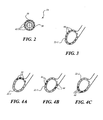
- FIG. 2 is a cross-sectional view showing an embodiment of a sensor 34 mounted on a shaft 36 of a tool.
- Shaft 36 may be configured to connect a handle portion of the tool with a distal portion, where the distal portion may include one or more functional elements.
- shaft 36 may correspond to shaft 14 shown in FIG. 1 .
- Sensor 34 may be mounted on a distal end of shaft 36 or along any portion of shaft 36.
- sensor 34 may be mounted on a portion of a tip located at the distal end of the tool.
- sensor 34 includes a support device 38 and a plurality of sensing elements 40 arranged circumferentially around support device 38.
- Each one of sensing elements 40 may be oriented in a direction facing away from shaft 36, wherein each sensing element 34 faces in a different angular direction.
- sensing elements 40 may include any suitable type of sensors and functionality, such as is mentioned above with respect to sensing element 20.
- Sensor 34 may include any number of sensing elements 40 and may be positioned and oriented in any suitable location, direction, or angle.
- sensing elements 40 may be mounted on support device 38 in a predetermined pattern according to a specific design.
- the number of sensing elements 40 may correspond to the number of haptic actuating devices positioned in a receptacle or recess of a handle of a tool.
- sensing elements 40 may be directly correlated with the haptic actuating devices located in receptacle 22 shown in FIG. 1 or with another set of actuating devices.
- the actuating devices may be arranged in a manner corresponding to the manner in which sensing elements 40 are arranged, or vice versa.
- sensing elements 40 can be formed or supported in a substantially circular arrangement.
- each actuating device can be matched with a corresponding sensing element 34.
- one actuating device can be designed to provide feedback based on the signals sensed by a corresponding sensing element 34 located in the same respective position of the arrangement.
- Sensor 34 is configured to measure one or more properties of the patient, which interacts or reacts with the surgical tool that supports sensor 34.
- FIG. 3 is a cross-sectional side view showing a first embodiment of a receptacle 22-1, which is part of a handle of a tool.
- receptacle 22-1 is a feedback portion of the handle.
- Receptacle 22-1 may correspond, for example, to a possible embodiment of receptacle 22 of surgical tool 10 shown in FIG. 1 .
- receptacle 22-1 includes a plurality of haptic actuating devices 44.
- the number of haptic actuating devices 44 in this embodiment is twelve, which corresponds to the same number of sensing elements 40 shown in FIG. 2 .
- the numbers of haptic actuating devices 44 and sensing elements 40 may be the same, different, multiples, etc.
- Haptic actuating devices 44 are supported by the material of receptacle 22-1 in any suitable manner. Haptic actuating devices 44 are configured to communicate a property of the patient measured by a corresponding group of sensing element. Haptic actuating devices 44 impose haptic effects on the user of the tool. More specifically, receptacle 22-1 may be configured to accommodate the thumb of one of the user's hands.
- Haptic actuating devices 44 may be distributed throughout receptacle 22-1. As illustrated, haptic actuating devices 44 are arranged in a substantially circular configuration. Each haptic actuating device 38 may be configured to correspond to a respective sensing element, such as sensing elements 40 ( FIG. 2 ), for imposing a haptic effect based on the signals sensed at the respect sensing element. One or more of haptic actuating devices 44 may be positioned in particular locations in receptacle 22-1 and actuated based on the sensed property of a respective sensing element corresponding to the location of the sensing elements with respect to the shaft.
- each haptic actuating device 38 may be configured to correspond to a particular direction in which a single sensor, such as sensing device 20 ( FIG. 1 ), is oriented.
- one or more sensors can be mounted on a grasper, and haptic actuating devices 44 may be configured to communicate the position of a portion of the object with respect to a jaw of the grasper. In this respect, if only a small portion of the object is within the jaws of the grasper, then only a small number of haptic actuating devices 44 are activated.
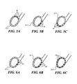
- FIGS. 4A - 4C are diagrams illustrating the activation of haptic actuating devices 44 shown in FIG. 3 according to a first implementation.
- haptic actuating devices 44 are designed to communicate directionality information to the user.
- processing device 30 shown in FIG. 1 may be configured to control haptic actuating devices 44 to convey information concerning directionality.
- the directionality information may represent the orientation of the tip of the tool, which can be controlled by physically turning the entire tool or by rotating a rotary device, such as rotary device 28.
- directionality information may represent the location that a sensor contacts the object, e.g., patient.
- the direction of a sensed parameter can vary with time. For example, a pulse may be detected in a first direction or at a first location at one time and then in a second direction or at a second location immediately thereafter.
- haptic actuating devices 44 that are located near a top portion of receptacle 22-1 are activated to correspond to sensor information related to a top portion of one or more sensors, an upper portion of the tool, an upward orientation, etc.
- a single sensor at the distal end of a tool can sense a property, e.g., stiffness, of the patient when that sensor is directed or oriented in an upward direction.
- a set of sensors formed around a distal end of a tool can be used, such that the sensors positioned in a top region sense a particular parameter, e.g., stiffness, or senses when a property at the top region reaches a specific level.
- haptic actuating devices 44 that are located near one or both of the sides of receptacle 22-1 are activated.
- the activation of these actuating devices 32 may correspond, for example, to sensor information of the patient received from a left or right region of the distal end of the tool.
- the activation of the side positioned haptic actuating devices 44 may correspond to the sensor being oriented or directed to the side.
- haptic actuating devices 44 on both the left and right side are activated simultaneously.
- haptic actuating devices 44 on only the right side or left side may be activated at a time, representing a specific feature at the right or left side of the distal end.
- activation of haptic actuating devices 44 on the sides may correspond to specific signals being sensed at the corresponding sensors.
- haptic actuating devices 44 that are located near the bottom of receptacle 22-1 are activated.
- the activation of the bottom haptic actuating devices 44 may correspond, for example, to sensor information of the patient received from a bottom region of the distal end of the tool.
- the detection of specific signals when the orientation of the sensor is in a downward direction can cause the activation of the bottom haptic actuation devices 32.
- the detection of specific signals from the bottom positioned or bottom directed sensors can cause the activation of the bottom haptic actuation devices 32.
- Haptic actuating devices 44 shown in FIGS. 4A-4C can also be actuated to indicate the direction or orientation of an end portion relative to a center shaft.
- the end portion may comprise an articulated grasper that can move with respect to the center shaft.
- Those haptic actuating devices 44 which are located at corresponding areas around the periphery can then be actuated to indicate the orientation of the head of the articulated grasper.
- FIGS. 5A - 5C are diagrams illustrating the activation of the haptic actuating devices 44 shown in FIG. 3 according to a second implementation.
- Haptic actuating devices 44 in this embodiment are designed to communicate any suitable type of information in a rotational fashion.
- haptic actuating devices 44 may be activated to indicate flow, such as blood flow through a blood vessel.
- haptic actuating devices 44 may be activated to indicate a structure, such as tubular structure.
- haptic actuating devices 44 show the activation of certain haptic actuating devices 44 at subsequent times. As shown in this example, some haptic actuating devices 44 located near the top of receptacle 22-1 are activated at one time. At a later time, the side haptic actuating devices 44 are activated. Then, the bottom haptic actuating devices 44 are activated. In this sense, a clockwise activation sequence is applied. In other embodiments, haptic actuating devices 44 may be activated in a counterclockwise fashion to communicate any relevant characteristic of the object. The pattern of activation can be used to indicate any parameter or feature of the patient. For example, the activation sequence may be used to communicate the sensing of a pulse.
- FIGS. 6A - 6C are diagrams illustrating the activation of the haptic actuating devices 44 shown in FIG. 3 according to a third implementation.
- Haptic actuating devices 44 in this embodiment are configured to communicate positional information or spatial information relative to a position on the tool.
- multiple sensors may be positioned in an array or other predetermined pattern and used to sense a particular parameter.
- FIG. 6A shows an example of activation of a small number of haptic actuating devices 44 when just a small portion of the object is held in the jaws.
- FIG. 6B shows an example of activation of a greater number of haptic actuating devices 44 when a larger amount of the object is within the grasp of the tool, e.g., about halfway in the tool's grasp.
- FIG. 6C shows an example of activation of all or nearly all haptic actuating devices 44 of receptacle 22-1 when the tool has a complete grasp of the object.
- haptic actuating devices 44 can communicate to the surgeon the type of grasp that is being applied to the patient's colon. Other delicate organs may also require a certain level of sensitivity as well.
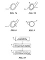
- FIG. 7 is a side view showing a second aspect of a receptacle 22-2, which is feedback portion of a handle of a tool.
- receptacle 22-2 may correspond to one possible aspect of receptacle 22 of surgical tool 10 shown in FIG. 1 .
- receptacle 22-2 includes a material that is configured to expand and contract in response to a signal related to a measured property of the object being tested. For example, in order to communicate a gripping force or other type of force on the object, the material of receptacle 22-2 may expand accordingly, thereby applying a force on all sides of the operator's thumb.
- the force applied to the user's hand can provide a more natural feeling to convey pressure sensed at the distal end of the tool, representing the pressure applied to the patient.
- a force feedback type output may provide the advantage of simulating a similar measurement of pressure and can be less distracting to the user than a vibrotactile sensation.
- FIG. 7A shows receptacle 22-2 in a contracted state, such as when no relevant signal is being sensed.
- receptacle 22-2 is shown in an expanded state, wherein the material expands from a normal position 48 to an expanded position 50.
- the material may be configured to return to its normal position 48 when the signal is no longer sensed, after a short period of time, or after some other specific event.
- the material capable of expanding and contracting may be used in other portions of the respective handle to apply pressure or force on other parts of the operator's hand.
- FIG. 8 is a side view showing a third aspect of a receptacle 22-3, which is feedback portion of a handle of a tool.
- receptacle 22-3 may correspond to one possible aspect of receptacle 22 of surgical tool 10 shown in FIG. 1 .
- receptacle 22-3 includes a programmable protrusion 54.
- Programmable protrusion 54 may be configured to have any suitable size and shape for properly communicating information to the user without causing great discomfort.
- Programmable protrusion 54 can communicate any type of information to the user, such as, for example, directional information, rotational information, relative position of an object with respect to one or more sensors, etc.
- Programmable protrusion 54 is designed to protrude toward the center of receptacle 22-3 so as to press against the skin of the user's thumb with a slight force to provide a greater contact with the thumb for allowing better communication with the nerves of the thumb.
- Programmable protrusion 54 may be configured to expand and contract to communicate specific conditions of the sensed signals. In some aspects, programmable protrusion 54 may be configured to vibrate or impose another type of haptic effect on the user's thumb. Programmable protrusion 54, according to other aspects, may be configured to change stiffness according to a sensed signal. In this case, programmable protrusion 54 may alter its stiffness based on a stiffness measurement made by the sensing elements in contact with the patient. Hence, the surgeon can receive an indication of stiffness to help identify organs and tissue.
- a plurality of protrusions are positioned around the inside surface of receptacle 22-3.
- Each protrusion can be actuated individually or in conjunction with some or all of the other protrusions.
- sensed signals can be processed in a way that includes the actuation of one or more of the protrusions.
- the protrusions can be actuated in the manner discussed with respect to FIGS. 4-6 to indicate direction, orientation, flow, degree or stage of a relative condition, etc.
- FIG. 9 is a cross-sectional side view diagram illustrating an aspect of a feedback portion of a handle 56.
- handle 56 includes a plurality of haptic actuating devices 58 positioned under the outer surface of handle 56.
- haptic actuating devices 58 can be positioned under the surface of handle 56, flush with the surface, on top of the surface, or in any combination thereof.
- FIG. 9 is directed to aspects where actuation is imposed on the user from an outer surface of handle 56.
- FIGS. 3-8 describes aspects that are directed to haptic actuation being imposed on the user from an inside surface of a finger/thumb receptacle.
- Handle 56 can be a part of any tool that is capable of imposing haptic feedback, and, in particular, a graspable tool where haptic actuation is applied from an outside surface of handle 56.
- the feedback portion of handle 56 can be incorporated into any type of tool or equipment, such as electric drills, electric screwdrivers, bicycle handle bars, motorcycle handle bars, tennis racquets, golf clubs, etc.
- haptic actuating devices 58 when haptic actuating devices 58 are arranged around the perimeter of handle 56 as shown, they can be programmed to function in a manner similar to the actuation techniques described above with respect to FIGS. 4-6 .
- FIG. 10 is a flow diagram of an aspect of a method of operation of a tool providing haptic feedback to its handle.
- a user or operator is allowed to manipulate a tool according to a normal use of the tool.
- the operator may manipulate a handle, buttons, or other feature on the tool to control a functional portion of the tool.
- the functional portion may be positioned, for instance, on an opposite end of the tool from the handle.
- the functional portion can be probed around to contact an object being tested or to be placed in proximity to the object being tested, depending on the particular type of parameter being measured.
- one or more properties of an object are sensed at a distal end of the tool.
- the property or properties may be sensed by one or more sensing devices.
- the sensors may be positioned on or near the functional portion of the tool.
- the sensed properties can be processed as needed to obtain output signals to be applied to output mechanisms on the tool. Based on the properties sensed and the types of output mechanisms incorporated in the tool, output signals can be obtained for each individual output mechanism or for an entire set of output mechanisms, depending on the particular application.
- one or more haptic effects are imposed on a portion of a handle of the tool.
- other output signals can be provided to the one or more other output mechanisms.
- the sensed signals are communicated to the operator in a haptic manner.
- the haptic effects may include haptic outputs, vibrotactile effect outputs, etc.
- routines, steps, processes, or operations described herein may represent any module or code sequence that can be implemented in software or firmware.
- these modules and code sequences can include commands or instructions for executing the specific logical routines, steps, processes, or operations within physical components.
- two or more of the routines, steps, processes, and/or operations described herein may be executed substantially simultaneously or in a different order than explicitly described, as would be understood by one of ordinary skill in the art.
Applications Claiming Priority (2)
| Application Number | Priority Date | Filing Date | Title |
|---|---|---|---|
| US12/354,302 US8216212B2 (en) | 2009-01-15 | 2009-01-15 | Providing haptic feedback to the handle of a tool |
| PCT/US2010/020010 WO2010083060A1 (en) | 2009-01-15 | 2010-01-04 | Providing haptic feedback to the handle of a tool |
Publications (2)
| Publication Number | Publication Date |
|---|---|
| EP2303140A1 EP2303140A1 (en) | 2011-04-06 |
| EP2303140B1 true EP2303140B1 (en) | 2015-03-25 |
Family
ID=41728010
Family Applications (1)
| Application Number | Title | Priority Date | Filing Date |
|---|---|---|---|
| EP10701044.9A Not-in-force EP2303140B1 (en) | 2009-01-15 | 2010-01-04 | Providing haptic feedback to the handle of a tool |
Country Status (4)
| Country | Link |
|---|---|
| US (1) | US8216212B2 (un) |
| EP (1) | EP2303140B1 (un) |
| JP (1) | JP5921195B2 (un) |
| WO (1) | WO2010083060A1 (un) |
Families Citing this family (46)
| Publication number | Priority date | Publication date | Assignee | Title |
|---|---|---|---|---|
| US20100312129A1 (en) | 2005-01-26 | 2010-12-09 | Schecter Stuart O | Cardiovascular haptic handle system |
| US20110046659A1 (en) * | 2007-07-09 | 2011-02-24 | Immersion Corporation | Minimally Invasive Surgical Tools With Haptic Feedback |
| EP2417925B1 (en) | 2010-08-12 | 2016-12-07 | Immersion Corporation | Electrosurgical tool having tactile feedback |
| WO2012047626A1 (en) * | 2010-09-27 | 2012-04-12 | University Of Pittsburgh - Of The Commonwealth System Of Higher Education | Portable haptic force magnifier |
| US9597143B2 (en) | 2010-11-05 | 2017-03-21 | Ethicon Endo-Surgery, Llc | Sterile medical instrument charging device |
| US9649150B2 (en) | 2010-11-05 | 2017-05-16 | Ethicon Endo-Surgery, Llc | Selective activation of electronic components in medical device |
| US9782214B2 (en) | 2010-11-05 | 2017-10-10 | Ethicon Llc | Surgical instrument with sensor and powered control |
| US9039720B2 (en) | 2010-11-05 | 2015-05-26 | Ethicon Endo-Surgery, Inc. | Surgical instrument with ratcheting rotatable shaft |
| US10881448B2 (en) | 2010-11-05 | 2021-01-05 | Ethicon Llc | Cam driven coupling between ultrasonic transducer and waveguide in surgical instrument |
| US9247986B2 (en) | 2010-11-05 | 2016-02-02 | Ethicon Endo-Surgery, Llc | Surgical instrument with ultrasonic transducer having integral switches |
| US9017851B2 (en) | 2010-11-05 | 2015-04-28 | Ethicon Endo-Surgery, Inc. | Sterile housing for non-sterile medical device component |
| EP2635216B1 (en) * | 2010-11-05 | 2021-09-01 | Cilag GmbH International | User feedback through handpiece of surgical instrument |
| US9526921B2 (en) | 2010-11-05 | 2016-12-27 | Ethicon Endo-Surgery, Llc | User feedback through end effector of surgical instrument |
| US9381058B2 (en) | 2010-11-05 | 2016-07-05 | Ethicon Endo-Surgery, Llc | Recharge system for medical devices |
| US9072523B2 (en) | 2010-11-05 | 2015-07-07 | Ethicon Endo-Surgery, Inc. | Medical device with feature for sterile acceptance of non-sterile reusable component |
| US20120116381A1 (en) | 2010-11-05 | 2012-05-10 | Houser Kevin L | Surgical instrument with charging station and wireless communication |
| US10660695B2 (en) | 2010-11-05 | 2020-05-26 | Ethicon Llc | Sterile medical instrument charging device |
| US9421062B2 (en) | 2010-11-05 | 2016-08-23 | Ethicon Endo-Surgery, Llc | Surgical instrument shaft with resiliently biased coupling to handpiece |
| US9017849B2 (en) | 2010-11-05 | 2015-04-28 | Ethicon Endo-Surgery, Inc. | Power source management for medical device |
| US20120116265A1 (en) | 2010-11-05 | 2012-05-10 | Houser Kevin L | Surgical instrument with charging devices |
| US9782215B2 (en) | 2010-11-05 | 2017-10-10 | Ethicon Endo-Surgery, Llc | Surgical instrument with ultrasonic transducer having integral switches |
| US9510895B2 (en) | 2010-11-05 | 2016-12-06 | Ethicon Endo-Surgery, Llc | Surgical instrument with modular shaft and end effector |
| US9011471B2 (en) | 2010-11-05 | 2015-04-21 | Ethicon Endo-Surgery, Inc. | Surgical instrument with pivoting coupling to modular shaft and end effector |
| US10959769B2 (en) | 2010-11-05 | 2021-03-30 | Ethicon Llc | Surgical instrument with slip ring assembly to power ultrasonic transducer |
| US9161803B2 (en) | 2010-11-05 | 2015-10-20 | Ethicon Endo-Surgery, Inc. | Motor driven electrosurgical device with mechanical and electrical feedback |
| US10085792B2 (en) | 2010-11-05 | 2018-10-02 | Ethicon Llc | Surgical instrument with motorized attachment feature |
| US9375255B2 (en) | 2010-11-05 | 2016-06-28 | Ethicon Endo-Surgery, Llc | Surgical instrument handpiece with resiliently biased coupling to modular shaft and end effector |
| US9089338B2 (en) | 2010-11-05 | 2015-07-28 | Ethicon Endo-Surgery, Inc. | Medical device packaging with window for insertion of reusable component |
| US9000720B2 (en) | 2010-11-05 | 2015-04-07 | Ethicon Endo-Surgery, Inc. | Medical device packaging with charging interface |
| EP2645943A1 (en) | 2010-12-02 | 2013-10-09 | Agile Endosurgery, Inc. | Surgical tool |
| US8801710B2 (en) * | 2010-12-07 | 2014-08-12 | Immersion Corporation | Electrosurgical sealing tool having haptic feedback |
| US8523043B2 (en) | 2010-12-07 | 2013-09-03 | Immersion Corporation | Surgical stapler having haptic feedback |
| US8942828B1 (en) | 2011-04-13 | 2015-01-27 | Stuart Schecter, LLC | Minimally invasive cardiovascular support system with true haptic coupling |
| US8845667B2 (en) * | 2011-07-18 | 2014-09-30 | Immersion Corporation | Surgical tool having a programmable rotary module for providing haptic feedback |
| WO2013036587A1 (en) * | 2011-09-07 | 2013-03-14 | St. Louis University | Foreign body location and retrieval device |
| DE102012200597A1 (de) * | 2012-01-17 | 2013-07-18 | Robert Bosch Gmbh | Vorrichtung zum Signalisieren von Informationen an den Fahrer eines Fahrrads |
| US10013082B2 (en) | 2012-06-05 | 2018-07-03 | Stuart Schecter, LLC | Operating system with haptic interface for minimally invasive, hand-held surgical instrument |
| US9443401B2 (en) * | 2013-09-06 | 2016-09-13 | Immersion Corporation | Automatic remote sensing and haptic conversion system |
| CN106163409B (zh) * | 2014-03-31 | 2022-09-02 | 皇家飞利浦有限公司 | 用于超声图像采集的触觉反馈 |
| US9880046B2 (en) * | 2014-05-15 | 2018-01-30 | Texas Instruments Incorporated | Method, apparatus and system for portable device surface and material analysis |
| US10136938B2 (en) | 2014-10-29 | 2018-11-27 | Ethicon Llc | Electrosurgical instrument with sensor |
| US10613629B2 (en) | 2015-03-27 | 2020-04-07 | Chad Laurendeau | System and method for force feedback interface devices |
| KR102016063B1 (ko) * | 2018-05-09 | 2019-08-29 | 건국대학교 글로컬산학협력단 | 복강경 그래스퍼의 촉감 압력 피드백을 제공하는 장치 및 그 구동 방법 |
| JP2021192130A (ja) | 2018-08-29 | 2021-12-16 | ソニーグループ株式会社 | 触覚提示装置及び触覚提示システム |
| NL2022018B1 (en) * | 2018-11-16 | 2020-05-26 | Efi Holding B V | Surgical instrument |
| CN112120791B (zh) * | 2020-09-30 | 2021-12-31 | 中国科学院深圳先进技术研究院 | 一种血管介入手术机器人主端操控装置 |
Citations (1)
| Publication number | Priority date | Publication date | Assignee | Title |
|---|---|---|---|---|
| US5609607A (en) * | 1993-09-24 | 1997-03-11 | Deutsche Aerospace Ag | Device for modeling or simulating the sense of touch in a surgical instrument |
Family Cites Families (13)
| Publication number | Priority date | Publication date | Assignee | Title |
|---|---|---|---|---|
| JPH0538327A (ja) * | 1991-04-23 | 1993-02-19 | Olympus Optical Co Ltd | 医療機器 |
| JPH06210581A (ja) * | 1993-01-20 | 1994-08-02 | Olympus Optical Co Ltd | 操作装置 |
| US5389849A (en) * | 1993-01-20 | 1995-02-14 | Olympus Optical Co., Ltd. | Tactility providing apparatus and manipulating device using the same |
| JPH0890458A (ja) * | 1994-09-21 | 1996-04-09 | Olympus Optical Co Ltd | 触覚伝達装置 |
| US6436107B1 (en) | 1996-02-20 | 2002-08-20 | Computer Motion, Inc. | Method and apparatus for performing minimally invasive surgical procedures |
| JP2836577B2 (ja) * | 1996-05-15 | 1998-12-14 | 日本電気株式会社 | マニピュレータ操作装置 |
| JPH1094512A (ja) * | 1996-09-25 | 1998-04-14 | Olympus Optical Co Ltd | 触覚検出装置 |
| US6810281B2 (en) * | 2000-12-21 | 2004-10-26 | Endovia Medical, Inc. | Medical mapping system |
| WO2001049227A1 (en) * | 2000-01-03 | 2001-07-12 | Johns Hopkins University | Surgical devices and methods of use thereof for enhanced tactile perception |
| US7196688B2 (en) | 2000-05-24 | 2007-03-27 | Immersion Corporation | Haptic devices using electroactive polymers |
| NL1018874C2 (nl) | 2001-09-03 | 2003-03-05 | Michel Petronella Hub Vleugels | Chirurgisch instrument. |
| AU2003238146A1 (en) | 2002-04-23 | 2003-11-10 | Yves Cadiou | Propeller with interactive blades |
| CA2520942C (en) | 2005-09-23 | 2013-03-19 | Queen's University At Kingston | Tactile amplification instrument and method of use |
-
2009
- 2009-01-15 US US12/354,302 patent/US8216212B2/en not_active Expired - Fee Related
-
2010
- 2010-01-04 EP EP10701044.9A patent/EP2303140B1/en not_active Not-in-force
- 2010-01-04 WO PCT/US2010/020010 patent/WO2010083060A1/en active Application Filing
- 2010-01-04 JP JP2011546271A patent/JP5921195B2/ja active Active
Patent Citations (1)
| Publication number | Priority date | Publication date | Assignee | Title |
|---|---|---|---|---|
| US5609607A (en) * | 1993-09-24 | 1997-03-11 | Deutsche Aerospace Ag | Device for modeling or simulating the sense of touch in a surgical instrument |
Also Published As
| Publication number | Publication date |
|---|---|
| JP5921195B2 (ja) | 2016-05-24 |
| JP2012515048A (ja) | 2012-07-05 |
| US20100179587A1 (en) | 2010-07-15 |
| US8216212B2 (en) | 2012-07-10 |
| WO2010083060A1 (en) | 2010-07-22 |
| EP2303140A1 (en) | 2011-04-06 |
Similar Documents
| Publication | Publication Date | Title |
|---|---|---|
| EP2303140B1 (en) | Providing haptic feedback to the handle of a tool | |
| EP2351528B1 (en) | Tool having multiple feedback devices | |
| EP2355709B1 (en) | Spatial array of sensors mounted on a tool | |
| EP2323564B1 (en) | Modular tool with signal feedback | |
| EP1911408B1 (en) | Manipulator | |
| US9554866B2 (en) | Apparatus and method for using a remote control system in surgical procedures | |
| US11135031B2 (en) | User interface device having grip linkages | |
| JP4680164B2 (ja) | マニピュレータ | |
| BR122022007761B1 (pt) | Aparelho cirúrgico | |
| RU2740114C1 (ru) | Хирургическая роботизированная система и хирургический инструмент для нее | |
| US20190380801A1 (en) | User interface device having finger clutch | |
| WO2013012837A1 (en) | Surgical tool having a programmable rotary module for providing haptic feedback | |
| JP2023504725A (ja) | 外科手術用アームを制御するためのユーザ入力デバイスの向き | |
| KR101267914B1 (ko) | 외과 수술 로봇 조작 장치 | |
| KR100997194B1 (ko) | 간접적으로 수술감을 제공하는 원격 수술 로봇 시스템 및 그 제어 방법 | |
| JP4747070B2 (ja) | マニピュレータ | |
| JP6586955B2 (ja) | 接触検出器具 | |
| WO2019240825A1 (en) | User interface device having finger clutch | |
| EP3241519B1 (en) | Devices and systems for locating pressure sensitive critical structures | |
| JP2021519629A (ja) | 医療装置のための制御ユニット | |
| EP3787852A1 (en) | User interface device having grip linkages |
Legal Events
| Date | Code | Title | Description |
|---|---|---|---|
| PUAI | Public reference made under article 153(3) epc to a published international application that has entered the european phase |
Free format text: ORIGINAL CODE: 0009012 |
|
| 17P | Request for examination filed |
Effective date: 20101116 |
|
| AK | Designated contracting states |
Kind code of ref document: A1 Designated state(s): AT BE BG CH CY CZ DE DK EE ES FI FR GB GR HR HU IE IS IT LI LT LU LV MC MK MT NL NO PL PT RO SE SI SK SM TR |
|
| AX | Request for extension of the european patent |
Extension state: AL BA RS |
|
| 17Q | First examination report despatched |
Effective date: 20120109 |
|
| DAX | Request for extension of the european patent (deleted) | ||
| RAP1 | Party data changed (applicant data changed or rights of an application transferred) |
Owner name: IMMERSION CORPORATION |
|
| RAP1 | Party data changed (applicant data changed or rights of an application transferred) |
Owner name: IMMERSION CORPORATION |
|
| GRAP | Despatch of communication of intention to grant a patent |
Free format text: ORIGINAL CODE: EPIDOSNIGR1 |
|
| INTG | Intention to grant announced |
Effective date: 20141021 |
|
| GRAS | Grant fee paid |
Free format text: ORIGINAL CODE: EPIDOSNIGR3 |
|
| GRAA | (expected) grant |
Free format text: ORIGINAL CODE: 0009210 |
|
| AK | Designated contracting states |
Kind code of ref document: B1 Designated state(s): AT BE BG CH CY CZ DE DK EE ES FI FR GB GR HR HU IE IS IT LI LT LU LV MC MK MT NL NO PL PT RO SE SI SK SM TR |
|
| REG | Reference to a national code |
Ref country code: GB Ref legal event code: FG4D |
|
| REG | Reference to a national code |
Ref country code: CH Ref legal event code: EP |
|
| REG | Reference to a national code |
Ref country code: IE Ref legal event code: FG4D |
|
| REG | Reference to a national code |
Ref country code: DE Ref legal event code: R096 Ref document number: 602010023363 Country of ref document: DE Effective date: 20150507 |
|
| REG | Reference to a national code |
Ref country code: AT Ref legal event code: REF Ref document number: 717366 Country of ref document: AT Kind code of ref document: T Effective date: 20150515 |
|
| PG25 | Lapsed in a contracting state [announced via postgrant information from national office to epo] |
Ref country code: FI Free format text: LAPSE BECAUSE OF FAILURE TO SUBMIT A TRANSLATION OF THE DESCRIPTION OR TO PAY THE FEE WITHIN THE PRESCRIBED TIME-LIMIT Effective date: 20150325 Ref country code: HR Free format text: LAPSE BECAUSE OF FAILURE TO SUBMIT A TRANSLATION OF THE DESCRIPTION OR TO PAY THE FEE WITHIN THE PRESCRIBED TIME-LIMIT Effective date: 20150325 Ref country code: NO Free format text: LAPSE BECAUSE OF FAILURE TO SUBMIT A TRANSLATION OF THE DESCRIPTION OR TO PAY THE FEE WITHIN THE PRESCRIBED TIME-LIMIT Effective date: 20150625 Ref country code: LT Free format text: LAPSE BECAUSE OF FAILURE TO SUBMIT A TRANSLATION OF THE DESCRIPTION OR TO PAY THE FEE WITHIN THE PRESCRIBED TIME-LIMIT Effective date: 20150325 Ref country code: SE Free format text: LAPSE BECAUSE OF FAILURE TO SUBMIT A TRANSLATION OF THE DESCRIPTION OR TO PAY THE FEE WITHIN THE PRESCRIBED TIME-LIMIT Effective date: 20150325 |
|
| REG | Reference to a national code |
Ref country code: AT Ref legal event code: MK05 Ref document number: 717366 Country of ref document: AT Kind code of ref document: T Effective date: 20150325 |
|
| REG | Reference to a national code |
Ref country code: LT Ref legal event code: MG4D |
|
| PG25 | Lapsed in a contracting state [announced via postgrant information from national office to epo] |
Ref country code: LV Free format text: LAPSE BECAUSE OF FAILURE TO SUBMIT A TRANSLATION OF THE DESCRIPTION OR TO PAY THE FEE WITHIN THE PRESCRIBED TIME-LIMIT Effective date: 20150325 Ref country code: GR Free format text: LAPSE BECAUSE OF FAILURE TO SUBMIT A TRANSLATION OF THE DESCRIPTION OR TO PAY THE FEE WITHIN THE PRESCRIBED TIME-LIMIT Effective date: 20150626 |
|
| RAP2 | Party data changed (patent owner data changed or rights of a patent transferred) |
Owner name: IMMERSION CORPORATION |
|
| PG25 | Lapsed in a contracting state [announced via postgrant information from national office to epo] |
Ref country code: NL Free format text: LAPSE BECAUSE OF FAILURE TO SUBMIT A TRANSLATION OF THE DESCRIPTION OR TO PAY THE FEE WITHIN THE PRESCRIBED TIME-LIMIT Effective date: 20150325 |
|
| PG25 | Lapsed in a contracting state [announced via postgrant information from national office to epo] |
Ref country code: CZ Free format text: LAPSE BECAUSE OF FAILURE TO SUBMIT A TRANSLATION OF THE DESCRIPTION OR TO PAY THE FEE WITHIN THE PRESCRIBED TIME-LIMIT Effective date: 20150325 Ref country code: RO Free format text: LAPSE BECAUSE OF FAILURE TO SUBMIT A TRANSLATION OF THE DESCRIPTION OR TO PAY THE FEE WITHIN THE PRESCRIBED TIME-LIMIT Effective date: 20150325 Ref country code: SK Free format text: LAPSE BECAUSE OF FAILURE TO SUBMIT A TRANSLATION OF THE DESCRIPTION OR TO PAY THE FEE WITHIN THE PRESCRIBED TIME-LIMIT Effective date: 20150325 Ref country code: ES Free format text: LAPSE BECAUSE OF FAILURE TO SUBMIT A TRANSLATION OF THE DESCRIPTION OR TO PAY THE FEE WITHIN THE PRESCRIBED TIME-LIMIT Effective date: 20150325 Ref country code: EE Free format text: LAPSE BECAUSE OF FAILURE TO SUBMIT A TRANSLATION OF THE DESCRIPTION OR TO PAY THE FEE WITHIN THE PRESCRIBED TIME-LIMIT Effective date: 20150325 Ref country code: PT Free format text: LAPSE BECAUSE OF FAILURE TO SUBMIT A TRANSLATION OF THE DESCRIPTION OR TO PAY THE FEE WITHIN THE PRESCRIBED TIME-LIMIT Effective date: 20150727 |
|
| PG25 | Lapsed in a contracting state [announced via postgrant information from national office to epo] |
Ref country code: AT Free format text: LAPSE BECAUSE OF FAILURE TO SUBMIT A TRANSLATION OF THE DESCRIPTION OR TO PAY THE FEE WITHIN THE PRESCRIBED TIME-LIMIT Effective date: 20150325 Ref country code: PL Free format text: LAPSE BECAUSE OF FAILURE TO SUBMIT A TRANSLATION OF THE DESCRIPTION OR TO PAY THE FEE WITHIN THE PRESCRIBED TIME-LIMIT Effective date: 20150325 Ref country code: IS Free format text: LAPSE BECAUSE OF FAILURE TO SUBMIT A TRANSLATION OF THE DESCRIPTION OR TO PAY THE FEE WITHIN THE PRESCRIBED TIME-LIMIT Effective date: 20150725 |
|
| REG | Reference to a national code |
Ref country code: DE Ref legal event code: R097 Ref document number: 602010023363 Country of ref document: DE |
|
| REG | Reference to a national code |
Ref country code: FR Ref legal event code: PLFP Year of fee payment: 7 |
|
| PG25 | Lapsed in a contracting state [announced via postgrant information from national office to epo] |
Ref country code: DK Free format text: LAPSE BECAUSE OF FAILURE TO SUBMIT A TRANSLATION OF THE DESCRIPTION OR TO PAY THE FEE WITHIN THE PRESCRIBED TIME-LIMIT Effective date: 20150325 |
|
| PLBE | No opposition filed within time limit |
Free format text: ORIGINAL CODE: 0009261 |
|
| STAA | Information on the status of an ep patent application or granted ep patent |
Free format text: STATUS: NO OPPOSITION FILED WITHIN TIME LIMIT |
|
| 26N | No opposition filed |
Effective date: 20160105 |
|
| PG25 | Lapsed in a contracting state [announced via postgrant information from national office to epo] |
Ref country code: IT Free format text: LAPSE BECAUSE OF FAILURE TO SUBMIT A TRANSLATION OF THE DESCRIPTION OR TO PAY THE FEE WITHIN THE PRESCRIBED TIME-LIMIT Effective date: 20150325 |
|
| PG25 | Lapsed in a contracting state [announced via postgrant information from national office to epo] |
Ref country code: BE Free format text: LAPSE BECAUSE OF NON-PAYMENT OF DUE FEES Effective date: 20160131 Ref country code: SI Free format text: LAPSE BECAUSE OF FAILURE TO SUBMIT A TRANSLATION OF THE DESCRIPTION OR TO PAY THE FEE WITHIN THE PRESCRIBED TIME-LIMIT Effective date: 20150325 |
|
| PG25 | Lapsed in a contracting state [announced via postgrant information from national office to epo] |
Ref country code: BE Free format text: LAPSE BECAUSE OF FAILURE TO SUBMIT A TRANSLATION OF THE DESCRIPTION OR TO PAY THE FEE WITHIN THE PRESCRIBED TIME-LIMIT Effective date: 20150325 Ref country code: LU Free format text: LAPSE BECAUSE OF FAILURE TO SUBMIT A TRANSLATION OF THE DESCRIPTION OR TO PAY THE FEE WITHIN THE PRESCRIBED TIME-LIMIT Effective date: 20160104 |
|
| REG | Reference to a national code |
Ref country code: CH Ref legal event code: PL |
|
| PG25 | Lapsed in a contracting state [announced via postgrant information from national office to epo] |
Ref country code: MC Free format text: LAPSE BECAUSE OF FAILURE TO SUBMIT A TRANSLATION OF THE DESCRIPTION OR TO PAY THE FEE WITHIN THE PRESCRIBED TIME-LIMIT Effective date: 20150325 |
|
| PG25 | Lapsed in a contracting state [announced via postgrant information from national office to epo] |
Ref country code: LI Free format text: LAPSE BECAUSE OF NON-PAYMENT OF DUE FEES Effective date: 20160131 Ref country code: CH Free format text: LAPSE BECAUSE OF NON-PAYMENT OF DUE FEES Effective date: 20160131 |
|
| REG | Reference to a national code |
Ref country code: IE Ref legal event code: MM4A |
|
| REG | Reference to a national code |
Ref country code: FR Ref legal event code: PLFP Year of fee payment: 8 |
|
| PG25 | Lapsed in a contracting state [announced via postgrant information from national office to epo] |
Ref country code: IE Free format text: LAPSE BECAUSE OF NON-PAYMENT OF DUE FEES Effective date: 20160104 |
|
| PG25 | Lapsed in a contracting state [announced via postgrant information from national office to epo] |
Ref country code: MT Free format text: LAPSE BECAUSE OF FAILURE TO SUBMIT A TRANSLATION OF THE DESCRIPTION OR TO PAY THE FEE WITHIN THE PRESCRIBED TIME-LIMIT Effective date: 20150325 |
|
| REG | Reference to a national code |
Ref country code: FR Ref legal event code: PLFP Year of fee payment: 9 |
|
| PG25 | Lapsed in a contracting state [announced via postgrant information from national office to epo] |
Ref country code: HU Free format text: LAPSE BECAUSE OF FAILURE TO SUBMIT A TRANSLATION OF THE DESCRIPTION OR TO PAY THE FEE WITHIN THE PRESCRIBED TIME-LIMIT; INVALID AB INITIO Effective date: 20100104 Ref country code: SM Free format text: LAPSE BECAUSE OF FAILURE TO SUBMIT A TRANSLATION OF THE DESCRIPTION OR TO PAY THE FEE WITHIN THE PRESCRIBED TIME-LIMIT Effective date: 20150325 Ref country code: CY Free format text: LAPSE BECAUSE OF FAILURE TO SUBMIT A TRANSLATION OF THE DESCRIPTION OR TO PAY THE FEE WITHIN THE PRESCRIBED TIME-LIMIT Effective date: 20150325 |
|
| PG25 | Lapsed in a contracting state [announced via postgrant information from national office to epo] |
Ref country code: MT Free format text: LAPSE BECAUSE OF FAILURE TO SUBMIT A TRANSLATION OF THE DESCRIPTION OR TO PAY THE FEE WITHIN THE PRESCRIBED TIME-LIMIT Effective date: 20160131 Ref country code: TR Free format text: LAPSE BECAUSE OF FAILURE TO SUBMIT A TRANSLATION OF THE DESCRIPTION OR TO PAY THE FEE WITHIN THE PRESCRIBED TIME-LIMIT Effective date: 20150325 Ref country code: MK Free format text: LAPSE BECAUSE OF FAILURE TO SUBMIT A TRANSLATION OF THE DESCRIPTION OR TO PAY THE FEE WITHIN THE PRESCRIBED TIME-LIMIT Effective date: 20150325 |
|
| PG25 | Lapsed in a contracting state [announced via postgrant information from national office to epo] |
Ref country code: BG Free format text: LAPSE BECAUSE OF FAILURE TO SUBMIT A TRANSLATION OF THE DESCRIPTION OR TO PAY THE FEE WITHIN THE PRESCRIBED TIME-LIMIT Effective date: 20150325 |
|
| PGFP | Annual fee paid to national office [announced via postgrant information from national office to epo] |
Ref country code: FR Payment date: 20190125 Year of fee payment: 10 Ref country code: GB Payment date: 20190128 Year of fee payment: 10 Ref country code: DE Payment date: 20190129 Year of fee payment: 10 |
|
| REG | Reference to a national code |
Ref country code: DE Ref legal event code: R119 Ref document number: 602010023363 Country of ref document: DE |
|
| GBPC | Gb: european patent ceased through non-payment of renewal fee |
Effective date: 20200104 |
|
| PG25 | Lapsed in a contracting state [announced via postgrant information from national office to epo] |
Ref country code: FR Free format text: LAPSE BECAUSE OF NON-PAYMENT OF DUE FEES Effective date: 20200131 Ref country code: GB Free format text: LAPSE BECAUSE OF NON-PAYMENT OF DUE FEES Effective date: 20200104 Ref country code: DE Free format text: LAPSE BECAUSE OF NON-PAYMENT OF DUE FEES Effective date: 20200801 |