EP2289597A1 - Guided radiation therapy system - Google Patents
Guided radiation therapy system Download PDFInfo
- Publication number
- EP2289597A1 EP2289597A1 EP10185676A EP10185676A EP2289597A1 EP 2289597 A1 EP2289597 A1 EP 2289597A1 EP 10185676 A EP10185676 A EP 10185676A EP 10185676 A EP10185676 A EP 10185676A EP 2289597 A1 EP2289597 A1 EP 2289597A1
- Authority
- EP
- European Patent Office
- Prior art keywords
- target
- isocenter
- beacon
- radiation
- sensors
- Prior art date
- Legal status (The legal status is an assumption and is not a legal conclusion. Google has not performed a legal analysis and makes no representation as to the accuracy of the status listed.)
- Withdrawn
Links
Images


Classifications
-
- A—HUMAN NECESSITIES
- A61—MEDICAL OR VETERINARY SCIENCE; HYGIENE
- A61N—ELECTROTHERAPY; MAGNETOTHERAPY; RADIATION THERAPY; ULTRASOUND THERAPY
- A61N5/00—Radiation therapy
- A61N5/10—X-ray therapy; Gamma-ray therapy; Particle-irradiation therapy
- A61N5/1048—Monitoring, verifying, controlling systems and methods
- A61N5/1049—Monitoring, verifying, controlling systems and methods for verifying the position of the patient with respect to the radiation beam
-
- A—HUMAN NECESSITIES
- A61—MEDICAL OR VETERINARY SCIENCE; HYGIENE
- A61B—DIAGNOSIS; SURGERY; IDENTIFICATION
- A61B34/00—Computer-aided surgery; Manipulators or robots specially adapted for use in surgery
- A61B34/20—Surgical navigation systems; Devices for tracking or guiding surgical instruments, e.g. for frameless stereotaxis
- A61B2034/2046—Tracking techniques
- A61B2034/2051—Electromagnetic tracking systems
-
- A—HUMAN NECESSITIES
- A61—MEDICAL OR VETERINARY SCIENCE; HYGIENE
- A61B—DIAGNOSIS; SURGERY; IDENTIFICATION
- A61B34/00—Computer-aided surgery; Manipulators or robots specially adapted for use in surgery
- A61B34/20—Surgical navigation systems; Devices for tracking or guiding surgical instruments, e.g. for frameless stereotaxis
- A61B2034/2072—Reference field transducer attached to an instrument or patient
-
- A—HUMAN NECESSITIES
- A61—MEDICAL OR VETERINARY SCIENCE; HYGIENE
- A61B—DIAGNOSIS; SURGERY; IDENTIFICATION
- A61B90/00—Instruments, implements or accessories specially adapted for surgery or diagnosis and not covered by any of the groups A61B1/00 - A61B50/00, e.g. for luxation treatment or for protecting wound edges
- A61B90/39—Markers, e.g. radio-opaque or breast lesions markers
- A61B2090/3954—Markers, e.g. radio-opaque or breast lesions markers magnetic, e.g. NMR or MRI
- A61B2090/3958—Markers, e.g. radio-opaque or breast lesions markers magnetic, e.g. NMR or MRI emitting a signal
-
- A—HUMAN NECESSITIES
- A61—MEDICAL OR VETERINARY SCIENCE; HYGIENE
- A61N—ELECTROTHERAPY; MAGNETOTHERAPY; RADIATION THERAPY; ULTRASOUND THERAPY
- A61N5/00—Radiation therapy
- A61N5/10—X-ray therapy; Gamma-ray therapy; Particle-irradiation therapy
- A61N5/1048—Monitoring, verifying, controlling systems and methods
- A61N5/1049—Monitoring, verifying, controlling systems and methods for verifying the position of the patient with respect to the radiation beam
- A61N2005/105—Monitoring, verifying, controlling systems and methods for verifying the position of the patient with respect to the radiation beam using a laser alignment system
-
- A—HUMAN NECESSITIES
- A61—MEDICAL OR VETERINARY SCIENCE; HYGIENE
- A61N—ELECTROTHERAPY; MAGNETOTHERAPY; RADIATION THERAPY; ULTRASOUND THERAPY
- A61N5/00—Radiation therapy
- A61N5/10—X-ray therapy; Gamma-ray therapy; Particle-irradiation therapy
- A61N5/1048—Monitoring, verifying, controlling systems and methods
- A61N5/1049—Monitoring, verifying, controlling systems and methods for verifying the position of the patient with respect to the radiation beam
- A61N2005/1051—Monitoring, verifying, controlling systems and methods for verifying the position of the patient with respect to the radiation beam using an active marker
-
- A—HUMAN NECESSITIES
- A61—MEDICAL OR VETERINARY SCIENCE; HYGIENE
- A61N—ELECTROTHERAPY; MAGNETOTHERAPY; RADIATION THERAPY; ULTRASOUND THERAPY
- A61N5/00—Radiation therapy
- A61N5/10—X-ray therapy; Gamma-ray therapy; Particle-irradiation therapy
- A61N5/1048—Monitoring, verifying, controlling systems and methods
- A61N5/1064—Monitoring, verifying, controlling systems and methods for adjusting radiation treatment in response to monitoring
- A61N5/1069—Target adjustment, e.g. moving the patient support
- A61N5/107—Target adjustment, e.g. moving the patient support in real time, i.e. during treatment
Definitions
- This invention relates generally to radiation therapy systems, and more particularly to systems and methods for accurately locating and tracking a target in a body to which guided radiation therapy is delivered.
- Recent advances in radiation therapy are providing new avenues of effective treatment for localized cancer. These include three-dimensional conformal external beam radiation, intensity modulated radiation therapy (TMRT), and stereotactic radiosurgery and brachytherapy. These newer treatment modalities deliver greater doses of radiation to the tumor, which accounts for their increased effectiveness when compared to standard external beam radiation therapy.
- TMRT intensity modulated radiation therapy
- stereotactic radiosurgery and brachytherapy These newer treatment modalities deliver greater doses of radiation to the tumor, which accounts for their increased effectiveness when compared to standard external beam radiation therapy.
- the margin may encompass some rectal, bladder and bulbar urethral tissues. It is highly desirable to provide a margin that does not encompass these important tissues.
- a tumor is identified within a patient's body with an imaging system, such as an X-ray, computerized tomography (CT), magnetic resonance imaging (MRI), or ultrasound system.
- CT computerized tomography
- MRI magnetic resonance imaging
- ultrasound system The approximate location of a tumor in the body is aligned with two or more alignment points on the exterior of the patient's body, and external marks are written on the patient's skin to mark the alignment points.
- the external marks are aligned with a reference system of the radiation delivery devices.
- This setup process attempts to accurately position the treatment target (or patient) isocenter within the body at a position in space where the radiation beam is focused, known as the machine isocenter.
- the effective patient treatment volume within the body is accurately registered (or positioned) to the radiation therapy treatment plan location. If, however, the target has moved relative to the external marks, then the target may be offset from the machine's isocenter, even when the external aligning devices and marks are properly aligned. Accordingly, the doctors and technicians cannot tell how far the target has actually moved relative to the machine's isocenter.
- a system and methods are provided for accurately locating and tracking the actual position of a target within a body in preparation for and during radiation therapy.
- the system is usable with a radiation delivery source that delivers a selected dose of radiation to the target in the body when the target is positioned at the machine isocenter of the radiation delivery source.
- the system includes a beacon fixable in or on the body at a selected position relative to the target, such as in or near the target.
- the beacon is excitable by an external excitation source to produce an identifiable signal while affixed in or on the body.
- a sensor array with a plurality of sensors is provided external of the body, and the sensors are spaced apart in a known geometry relative to each other.
- a data-processing unit is coupled to the sensor array and is configured to use the measurements from the sensors to determine the actual location of the beacon and a target isocenter within the target relative to the sensors.
- a reference marker is also coupled to the radiation delivery device at a known position relative to the device's machine isocenter. The reference marker provides a measurable signal for determining the position of the reference marker and the machine isocenter relative to the sensor array.
- the data-processing unit is configured to compare the position of the target isocenter with the position of the machine isocenter in real time to determine whether the patient is properly setup for the radiation therapy.
- a monitoring system is coupled to the data-processing unit and has a feedback portion configured to provide feedback information about the actual position of the target isocenter relative to the machine isocenter.
- the feedback portion provides a visual and/or numeric representation of the positions of the machine isocenter and target isocenter relative to each other. This representation may then be used to adjust the position of the target isocenter before or during therapy.
- the feedback portion provides a visual and/or numeric display of the real-time movement of the target isocenter relative to the machine isocenter.
- the feedback data may be used to automatically alert the operator of patient or target movement beyond acceptable limits.
- the feedback data may be used to automatically adjust, gate or shutoff the radiation therapy treatment for normal (i.e. respiration) or unplanned patient motion.
- an adjustable patient support assembly is combined with the tracking and monitoring system for use with the radiation delivery system.
- the support assembly includes a base, a support structure movably attached to the base, and a movement control device connected to the support structure in order to selectively move the support structure relative to the base.
- the plurality of sensors spaced apart from each other are coupled to the base in a fixed location relative to the base.
- the data-processing unit is coupled to the sensors to receive the signal measurement data from one or more beacons in or next to the target.
- the data-processing unit is configured to use the signal measurement data for each beacon to determine the actual location of the beacon and target isocenter within the target.
- the data-processing unit is configured to identify the location of the target isocenter relative to the machine isocenter.
- the movement control device is coupled to the data-processing unit and is adapted to position the target isocenter coincident with the machine isocenter in response to data from the data processing unit.
- a method for delivering radiation therapy on a selected target within a body.
- the method incudes positioning an excitable beacon at a selected position relative to the target, exciting the implanted beacon with an excitation source external of the body to produce an identifiable beacon signal and measuring the beacon signal from the beacon with a plurality of sensors exterior of the body, positioned in a known geometry relative to each other.
- the method also includes determining the location of the beacon and a target isocenter in the body relative to the sensors based upon the measurements of the beacon signal from the sensors.
- the method further includes determining the location of a machine isocenter of the radiation delivery assembly relative to the sensors and relative to the target isocenter, and positioning the body relative to the radiation delivery device so the target isocenter is coincident with the machine isocenter. Radiation therapy is then applied from the radiation delivery device to the treatment volume about the target isocenter.
- a method for positioning a body relative to a radiation delivery device for delivering radiation therapy to a treatment volume at a target isocenter within the body.
- the body has a selected target therein, and at least one excitable beacon is positioned in a known position relative to the target.
- the method includes positioning the body on a movable support assembly adjacent to a plurality of sensors, and energizing the excitable beacon with an excitation source exterior of the body.
- the excited beacon provides an identifiable beacon signal.
- the beacon signal is measured with the plurality of sensors positioned exterior of the body and in a known geometry relative to each other and relative to the movable support assembly.
- the location of the beacon and a target isocenter within the treatment volume is determined based on the measurements by the sensors of the beacon signal.
- the location of the target isocenter is also determined relative to the plurality of sensors and relative to the machine isocenter.
- the location of the target isocenter is compared to the location of the machine isocenter, and if the two isocenters are not coincident with each other, a portion of the support assembly moves the body and target to position the target isocenter coincident with the machine iso center.
- Figures 1-17 illustrate a system and several components for locating, tracking and monitoring a target within a body in accordance with embodiments of the present invention.
- the system and components are usable to locate, track, monitor, and evaluate a target for application of a selected therapy to the target, such as guided radiation therapy.
- a selected therapy such as guided radiation therapy.
- one aspect of the present invention provides a system 10 configured for use in applying guided radiation therapy to a target 12, such as a tumor, within the body 14 of a patient 16.
- the system 10 allows the target 12 to be located within the patient's body 14 and the actual position monitored in real time while applying ionizing radiation therapy to the target from a radiation delivery source 18.
- the target 12 may move within the body 14 because of breathing, organ filling or emptying, or other internal movement.
- the target motion is tracked and monitored relative to the radiation beam to insure accurate delivery of radiation to the target 12 and, if needed, only a minimum margin around the target.
- the system 10 is discussed below in connection with guided radiation therapy for radiation of a tumor or other target, the system can be used for tracking and monitoring other targets within a body, such as for other therapeutic or diagnostic purposes.
- the radiation delivery source 18 of the illustrated embodiment is an ionizing radiation device, known as a linear accelerator, but could be any radiation therapy delivery device.
- Other radiation therapy delivery devices can be used, including such devices manufactured by Varian Medical Systems, Inc. of Palo Alto, California; Siemans Medical Systems, Inc. of Iselin, New Jersey; Electa Instruments, Inc. of Iselin, New Jersey; or Mitsubishi Denki Kabushik Kaisha of Japan.
- Such devices are used to deliver conventional single or multi-field radiation therapy, 3D conformal radiation therapy (3D CRT), inverse modulated radiation therapy (IMRT), stereotactic radiotherapy, tomo therapy. This is done in conjunction with a variety of treatment planning software systems.
- the radiation delivery source 18 delivers a gated, contoured or shaped beam 19 of ionizing radiation from a movable gantry 20 to a area or volume referenced to a point at a location away from the gantry.
- This point in space referred to as a machine isocenter 22, is the point to which the ionizing radiation beam 19 is configured about as determined by industry standard treatment planning processes.
- the system 10 allows the target 12 to be accurately positioned at the machine isocenter 22 so the ionizing radiation is accurately delivered to the target 12.
- the system also allows the target's actual position relative to the machine isocenter 22 to be monitored during the radiation therapy so as to minimize collateral damage to healthy tissue surrounding the target.
- the illustrated system 10 includes a plurality of beacons 30 positioned in or adjacent to the target 12 to mark the target's actual location in the body 14. Accordingly, the beacons 30 are markers in, on or near the body. In one example, the beacons 30 may be attached to patient-immobilization devices at known locations relative to the treatment isocenter.
- the beacons 30 are energized or excited by an excitation source 32 positioned exterior of the patient's body 14. When the beacons 30 are excited, they each resonate at a selected unique frequency and generate a low energy radio-frequency magnetic signal measurable from outside of the body 14.
- the signals from the beacons 30 are detected and measured by an array 34 of sensors 36 located exterior of the patient's body 14.
- the sensors 36 are positioned in a fixed, selected geometry relative to each other, so the array 34 defines a fixed reference coordinate system from which location and movement are calculated.
- the sensors 36 are operatively coupled to a computer controller 38 that receives the measurement information from each sensor and determines the actual location of the beacons 30 within the patient's body 14 relative to the sensors.
- the computer controller 38 includes algorithms used to define and determine the location of the target isocenter 40 within the target 12, based upon the signal measurements by the sensors 36 from the resonating beacons. In another embodiment, the location of the target isocenter 40 within the target 12 is selected, and the computer controller 38 utilizes position information about the position and/or orientation of each beacon 30 relative to the selected target isocenter.
- the target isocenter 40 is the point or position within the target to which the shaped dose of radiation is configured around or referenced to as determined by a treatment planning process.
- the sensors 36 are polled twelve or more times per minute to track the actual position of the target isocenter 40 within the patient's body 14 relative to the sensor array 34. Accordingly, the actual position of the target 12 and the target isocenter 40 can be monitored in real time when the patient is positioned adjacent to the sensor array 34.
- the actual position of the target isocenter 40 is compared to the position of the machine isocenter 22 relative to the sensor array 34.
- the illustrated system 10 has a reference device 42 positioned on the gantry 20 of the linear actuator or another selected position on a radiation therapy delivery device used in alternate embodiments.
- the other radiation therapy delivery device can include cobalt machines, a Gamma Knife, a Cyberknife, specialized stereostatic radiotherapy devices, or a TomoCT assembly (which utilizes a linear actuator in a CT scanner).
- the reference devise 42 is positioned at a known spatial or geometric relationship relative to the machine isocenter 22.
- the reference device 42 in one embodiment is a resonating, three axis, single frequency beacon that provides a measurable signal detectable by the sensors 36 in the array 34.
- the reference device 42 in alternate embodiments can be positioned in a remote location away from the gantry 20. In either embodiment, the location of the machine isocenter 22 relative to the sensor array 34 can be calculated upon determining the position of the reference device 42 relative to the sensor array.
- the sensors 36 provide the measurement data about the reference device 42 to the computer controller 38, and the computer controller calculates the location of the machine isocenter 22 relative to the sensor array 34.
- the location of the target isocenter 40 relative to the sensor array 34 is compared to the position of the machine isocenter 22 relative to the sensor array. If the target isocenter 40 and machine isocenter 22 are spatially misaligned such that the two isocenters are not three-dimensionally coincident with each other, the patient 16, and/or target 12 can be moved relative to the machine isocenter 22. The target 12 position is moved until the target isocenter 40 is coincident with the machine isocenter 22.
- the radiation delivery source 18 can be activated to provide the ionizing radiation beam 19 referenced to the target isocenter, thereby irradiating the target according to a radiation treatment plan, while minimizing or eliminating collateral damage to healthy tissue surrounding the target 12.
- the actual location of the target isocenter 40 can also be monitored in real time during the radiation therapy to ensure that the target isocenter does not move an unacceptable amount relative to the machine isocenter 22 and allow for treatment when the treatment isocenter and the machine isocenter are within acceptable displacement limits.
- the system 10 also includes a monitoring assembly 44 coupled to the computer controller 38 that provides feedback data to a user interface for the doctor or technician operating the system and/or the radiation delivery device 18.
- the monitoring assembly 44 can provide the feedback data as a visual representation of the target isocenter's position in three-dimensional space relative to the machine isocenter's position in real time as the patient is being set up and positioned for the radiation therapy.
- the monitoring assembly 44 can also provide other feedback data to the user interface including, for example, confirmation of setup completion, graphical information, patient information, radiation treatment plan information, or other information that can be utilized during the guided radiation therapy process.
- FIGs 3-5 illustrate excitable beacons 30 of alternate embodiments usable in the system 10.
- One of the beacons 30 shown in Figure 3 is an implantable, single-axis, resonating beacon 31 having a ferrite core 46 wrapped by a conductive winding 48, and the winding is connected to a small capacitor 50.
- the beacon 31 is configured to be energized by the external excitation source 32, which produces an electromagnetic field. This electromagnetic field causes the beacon 31 to resonate at a predetermined frequency, thereby providing a signal of sufficient intensity to be measured by the sensors 36 ( Figure 1 ) from outside of the body.
- a biologically inert coating 52 encapsulates the ferrite core 46, the winding 48, and the capacitor 50 so as to provide a small, self-contained, wireless excitable beacon 31 that can be permanently implanted into the patient.
- the beacon 31 is "wireless" because it need not be physically connected via wires to an outside energy source for generation or communication of the beacon signal.
- the beacon 31 has a length of only approximately 5 mm and diameter sized to fit through an applicator needle.
- the beacon 31 in other embodiments can have different sizes as needed for the desired configuration of the beacon signal.
- another one of the excitable beacons 30 includes a three-axis, wireless, resonating beacon 52 with three signaling portions 54.
- Each signaling portion 54 is positioned axially perpendicular to the other two signaling portions. Accordingly, the three signaling portions 54 define an X, Y, Z reference coordinate.
- Each of the signaling portions 54 includes a ferrite core 46, a winding 48 around the ferrite core, and a small capacitor 50 connected to each winding.
- Each signaling portion is configured to be energized by the external excitation source 32, and to resonate at a frequency different than the resonating frequency of the other two signaling portions.
- the three-axis beacon 52 includes a biologically inert coating 56 that encapsulates all three of the signaling portions 54, so the beacon can be permanently implanted in the patient's body.
- each of the beacon's signaling portions resonates at its selected frequency and provides the measurable beacon signal at an intensity so it can each be measured by the sensor array 34 ( Figure 1 ).
- Frequency multiplexing by the computer controller allows the computer controller 38 to differentiate between the beacon signals from the different signaling portions of the beacon when calculating the beacon's position and orientation relative to the sensor array.
- another embodiment of the beacon 30 includes a cube-shaped beacon 58 with a single ferrite core 60 and three sets of windings 62 axially oriented perpendicular to each other to define the X, Y, and Z axes for the beacon.
- Each winding 62 is connected to a small capacitor 64 and configured to resonate at a frequency different than the other two winding.
- the cube-shaped beacon 58 is also a wireless, three-axis, resonating beacon.
- the wireless, excitable beacons 30 are configured to resonate and provide a measurable signal within the frequency range of approximately 10kHz to 200kHz, inclusive.
- the beacons 30 can be self-contained, powered markers that include a power source, such as a battery, that provides sufficient power to produce the measurable identifiable beacon signal.
- the beacons 30 can be "wired" beacons connectable via wires to a selected power or excitation source to allow the beacons to generate the unique beacon signal.
- the beacon signal can be unique as a function of frequency (i.e., frequency multiplexing) as a function of time or time multiplexing.
- a single beacon 31, preferably a singleaxis beacon, is implanted in the target 12, and the intensity of the signals from the single resonating beacon is used to determine the target location information relative to the sensor array 34.
- two, three, or more beacons 30 are implanted at known locations in or adjacent to the target. Each beacon 30 produces its unique signal relative to the other beacons, so the sensor array 34 differentiates between the beacons by frequency multiplexing. The sensor array 34 measures the intensity of the unique signals from the beacons 30.
- the signal intensity measurements are converted for use in geometric calculations (discussed in greater detail below) to accurately determine the actual three-dimensional location (X, Y, Z) and possibly the angular orientation (pitch, yaw, roll) of the beacon relative to the sensor array 34.
- the system 10 includes the excitation source 32 that generates a magnetic field for exciting the beacons 30.
- the excitation source is positioned in a selected location relative to the target 12 and close enough to the beacons 30 so the emitted magnetic field has sufficient intensity to acceptably energize the beacons.
- a plurality of beacons 30 are permanently implanted within the patient's body 14 in or adjacent to the target 12.
- the computer controller 38 provides a separate driver circuit for the excitation source 32 for each beacon 30, so as to selectively excite the respective beacon at the selected frequency.
- the excitation source 32 in one embodiment is a three-dimensional, AC magnetic field source that generates three-dimensional magnetic fields in the X, Y, and Z axes.
- This excitation source 32 provides one source coil for each beacon 30, and the electric current driven through the source coil generates the AC magnetic waveform tuned for the respective beacons.
- the source coil (or coils) in the excitation source 32 is provided by a coils configured to generate the multiple or scanned excitation frequency fields for the respective beacons 30.
- Figures 6 and 7 are schematic isometric views of sensor arrays 34 positionable exterior of the body ( Figure 6 ) and spaced apart from the beacons 30 positioned in or near the target 12. In these illustrated embodiments, three beacons 30 are shown implanted in or near the target 12.
- the sensor array 34 includes a frame 70 that supports a plurality of sensors 36 in a fixed and known geometry relative to each other along X, Y, or Z axes of a reference coordinate system 72. The position of each sensor 36 on the frame 70 relative to the reference coordinate system 72 is fixed and defines fixed reference points for obtaining measurement data used by the computer controller 38.
- the frame 70 supports the sensors 36 so the sensors are positioned in a single plane.
- the frame 70 is shaped to support the sensors 36 in two orthogonal planes, so the sensors 36 are oriented along the X, Y, and Z axes of the reference coordinate system 72. Accordingly, the sensor array 34 provides the fixed reference structure from which measurements are taken and calculations performed to determine the relative positions of the target 12, the target isocenter 40 and the machine isocenter 22.
- Each sensor 36 is a three-axis sensor that measures the absolute beacon signal strengths from a respective one of the beacons 30 relative to the X, Y, and Z axes.
- the absolute signal strength of the beacon signal along each axis in the reference coordinate system 72 is measured by the sensors 36 for each beacon in order to determine the X, Y, and Z position of each beacon.
- the distance of the beacon from the sensor can be determined based upon the beacon's signal strength.
- the geometric relationship from the beacon to a series of sensors that are spaced at known locations relative to each other is used to solve a series of equations with one unique result. Accordingly, the distance between the beacon 30 and the sensor 36 calculated by the computer controller 38 based on the beacon's signal strength measured by the respective sensors and iterated for a best fit solution to the geometric equations.
- the precise location of a beacon 30 in space relative to the sensor array 34 can be calculated based upon the distances between that beacon and at least four separate three-axis sensors spaced apart from each other in the array.
- the absolute magnitude of the distance from the three-axis sensor is determined by squaring the each of the three axis magnitudes (x, y, and z orientations), adding the results and finally taking the square root for the distance resultant.
- the distance between one sensor 36 and one of the beacons 30 corresponds geometrically to the radius of a sphere.
- Figure 8 shows two illustrative spheres 100 with the center points 102 each defined by a separate sensor 36. When two spheres 100 intersect, the intersection defines a circle 104.
- the beacon is located at some point on that circle.
- three spheres 100 intersect shown in Figure 9 , the intersection defines one of two points 105 where the beacon is located on that line.
- the intersection defines a single point 108 in space corresponding to the precise position of the beacon 30 in space relative to the sensor array 34.
- the sensor array 34 can include only four three-axis sensors 36 to determine that beacon's position in space. Since the signals are frequency multiplexed and multiple frequencies may be received with each sensor coil and each individual frequency component may be examined by processing the combined signal with a fast Fourier transform (FFT) in the control electronics, multiple beacons may be located with the same sensors.
- FFT fast Fourier transform
- the sensor array 34 is configured at known geometric orientations relative to the reference coordinate system 72, so that the beacon signal measurements can be used by the computer controller 38 to calculate the angular orientation of the treatment volume (i.e., the pitch,yaw and roll) in space relative to the reference coordinate system 72 by using the three sets of three dimensional data (x, y, and z from the single axis beacons). Based upon the position of the beacons 30 relative to the target, the location and angular orientation of the target 12 can be determined by the computer controller 38.
- the beacon signal may be separated from the signal generated by the excitation source 32 via signal processing software or electronics in a number of ways.
- the excitation source 32 is turned or gated “on” to excite the beacon and then turned or gated “off” to allow for measurement of the beacon response without interference by the signal from the excitation source.
- the beacon 30 will continue to resonate after the excitation source 32 is gated “off” for a period determined by the sensor's electric inductance, capacitance and series resistance.
- the system is operated in continuous wave (CW) mode were the excitation source 32 remains “on” during measurement of the beacons 30.
- the beacon signal is 90 degrees “out of phase” with the signal from the excitation source, so the beacon signal is removed from the excitation signal.
- the output frequency of the excitation source's signal is continuously varied or scanned to maximize the excitation of the beacons 30 which results in a maximum beacon signal while minimizing or eliminating unwanted excitation signal.
- the position of each beacon 30 relative to the target 12 and relative to the target isocenter 40 is also calculated or determined.
- the target isocenter 40 in the target 12 is chosen first based upon imaging data about the target provided by an imaging system, such as a CT scan, MRI, ultrasound system, or nuclear imaging system (e.g. positron emission tomography). Once the target isocenter 40 is selected, the position of each implanted beacon 30 is measured relative to the target isocenter 40. The position of the target isocenter 40 is then determined relative to the reference coordinate system 72 based upon defining the location of each beacon 12 relative to the reference coordinate system.
- the target isocenter 40 is defined as a function of the beacon locations relative to the target 12.
- the beacons 30 are selectively positioned in or near the target 12 and the orientation of the beacons is used to define and calculate the target isocenter.
- the target isocenter 40 within the target 12 can be defined and its position determined relative to beacons 30 and the reference coordinate system 72 even if the beacons 30 are not actually implanted within or even immediately adjacent to the target 12.
- the beacons 30 are, however, positioned close enough to the target 12 so that if the target moves, the target and beacons move together substantially as a unit. Therefore, movement of the target 12 is monitored by tracking movement of the beacons 30 relative to the sensor array 34.
- the system 10 is configured to track motion of the target 12 in real time.
- the computer controller 38 acquires data from each sensor 36 and outputs a result approximately 12 times per second.
- the computer controller obtains measurement data from the sensors 36 and calculates the location of the target isocenter 40 relative to the sensor array every five seconds.
- the computer controller 38 can measure the sensors 36 to monitor in real time the motion of the particular target isocenter 40 relative to the sensor array 34.
- the measurement update rate may be reduce as to allow for sufficient data averaging to reduce the measurement noise at the same time allowing for an adequate update rate for the user.
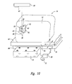
- Figure 10 is a partial isometric view illustrating an aspect of the present invention that includes a support table 76 that movably supports the patient's body 14 under the gantry 20 and adjacent to the sensor array 34.
- the support table 76 is positionable below the machine isocenter 22.
- the support table 76 is movable to adjust the position of the patient 16 relative to the machine isocenter 22 until the target isocenter 40 is coincident with the machine isocenter.
- the sensor array 34 may be placed on, under, or connected to the support table 76. Alternatively, it may be mounted to the linear accelerator's gantry at a location sufficiently close to any beacons 30 (implanted, external or gantry) that are to be located. In this alternate embodiment with the sensor array 34 mounted to the linear accelerator, the position from the machine isocenter 22 to the sensor array will be known, so that a separate gantry beacon 42 may not be used.
- the support table 76 has a base 88 and a tabletop 90 movably supported to the base for linear and angular movement relative to the sensor array 34.
- a movement control system 78 is connected to the tabletop 90 to control movement of the tabletop and the patient 16 relative to the machine isocenter 22 and the sensor array 34.
- the control system 78 is also coupled to the computer controller 38, and the computer controller 38 is programmed to activate the control system 78 to adjust the linear or angular position of the patient.
- the tabletop's position moves in response to an authorized user such as doctor, physicist or technician activating the control system, or automatically in response to instructions provided by the computer controller 38.
- ionizing radiation can be selectively and very accurately delivered directly to the target area or volume.
- Application of the radiation therapy to the target 12 can be provided at the selected dosage and intensity with precise accuracy, while potentially minimizing the margin needed around the target.
- the actual position of the target isocenter 40 is substantially continuously monitored and tracked relative to the machine isocenter 22 during delivery of the radiation therapy. If the target isocenter 40 moves away from the machine isocenter 22 beyond an acceptable range of displacement distances, the computer controller 38 provides a signal to the radiation delivery device to interrupt the radiation therapy to the target.
- the target's position can then be adjusted manually or automatically until the target isocenter 40 is again coincident with the machine isocenter 22, and radiation therapy can resume.
- the computer controller 38 is programmed so that if the target isocenter 40 moves from the machine isocenter 22, but the distance of movement does not exceed the acceptable range, the computer controller 38 will not interrupt the radiation therapy. This range of movement is dependent upon many factors, such as the target type (e.g., prostate, lung, liver), target size, target location, beam shape/size, and the radiation treatment plan.
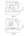
- FIGs 11 and 12 illustrate a feedback portion 80 of the monitoring assembly 44 that provides feedback data to an operator about, as an example, the position of the beacons 30, the target isocenter 40 and the machine isocenter 22.
- the feedback portion 80 is a display monitor that provides pictorial, graphical, or textual information to the operator.
- Other feedback portions 80 such as graphical display devices, auditory feedback devices, or visual feedback devices can be used in alternate embodiments.
- the computer controller 38 contains imaging data, such as from a CT, MRI, or ultrasound imaging system, that defines the shape and size of the target 12 within the body 14. The imaging data also defines the locations of each beacon 30 in or around the target 12.
- the computer controller 38 uses the imaging data to provide a simulated model of the target, the beacons, and the target isocenter.
- This simulated model is displayed on the feedback portion 80 as shown in Figure 11 in phantom lines.
- the simulated model is also displayed overlaying the machine isocenter 22, so the simulated target isocenter 40 is coincident with the machine isocenter.
- the simulated target and simulated beacons can also display how the actual target needs to be positioned and oriented three-dimensionally for the particular radiation therapy to be applied to the target.
- the monitoring assembly 44 also receives and display information from the computer controller 38 to show the actual locations of the beacons 30 and target isocenter 40 relative to the machine isocenter 22, and relative to the simulated target and beacons. Accordingly, the feedback portion 80 allows the operator to determine the actual position of the beacons relative to the simulated beacons, and the target isocenter 40 relative to the machine isocenter 22 substantially in real time while the patient 16 is on the support table 76 ( Figure 1 ). The patient 16 and support table 76 can be repositioned until the target 12 is properly oriented for the selected radiation therapy.
- the system 10 is also usable to monitor the status of the target, such as a tumor or the like, in a patient's body 14 over time.
- Figures 13 and 14 are schematic views showing a tumor 90 in a body 92.
- Three beacons 30 are shown for this embodiment permanently implanted in or adjacent to the tumor 90. Images of the tumor 90 and beacons 30 are obtained by CT, MRI, ultrasound, or other imaging technique over time. From these multiple images of the tumor 90 and beacons 30, the position of the beacons relative to the tumor can be compared and tracked. Accordingly, a doctor can use the beacons 30 in the multiple images as a reference tool to determine whether the tumor has shrunk, grown, moved, or otherwise changed within the patient's body.
- Figure 13 illustrates an image of a tumor 90 in a first condition with three beacons 30 implanted therein
- Figure 14 illustrates a second image of the tumor taken later in time.
- the second image shows the same beacons 30 in the same location within the patient's body, and from the position of the tumor relative to the beacons, one can see that the tumor has shrunk.
- doctors can track the status of tumors or other targets within the body over time to determine, as an example, the effectiveness of radiation therapy, whether additional treatments are needed, or whether a change in tumor growth has occurred or whether the radiation treatment plan needs to be altered.
- the beacons 30 are described and shown as being subcutaneously implanted in or next to a target 12. This implantation of the beacons 30 is performed when needed to ensure that, if the target 12 moves, the beacons will move with the target as a unit.
- the beacons are surface-mounted beacons 110 adhered to the exterior surface 112 of the patient's body 14 substantially adjacent to and in alignment with a target 12, in or on the body.
- the surface-mounted beacons 110 can be removably adhered with an adhesive, such as tape or the like, in a substantially fixed location on the body's exterior surface 112 relative to the target 12.
- These surface-mounted beacons 110 are particularly suitable for targets 12 known not to substantially move within the body 14 relative to the exterior surface.
- the surface-mounted beacons 30 are also suitable for use when the target's size or location in the body 14 is such that some motion of the target isocenter is not critical for effective radiation therapy or treatment. Accordingly, the surface-mounted beacons 110 provide reference points for accurate alignment and orientation of the target 12 and the machine isocenter 22.
- beacons 30 may be mounted on or in patient immobilization devices at known locations relative to the treatment isocenter.
- the surface-mounted beacons 110 in one embodiment are wireless beacons, so that the beacons can remain adhered on the patient's body 14 after a radiation treatment session so that the patient 16 can come and go from the treatment area without disrupting the position of the beacons 110 relative to the target 12.
- the beacons 110 remain adhered to the patient 16 and are connectable to lead wires of a "wired" marker system in the treatment area.
- the lead wires can be disconnected from the beacons 110 to allow the patient 16, to leave the treatment area while the beacons remain fixed in place on the patient's body.
- the surface-mounted beacons 110 are also usable to monitor a patient's base-line girth (anterior-posterior and lateral dimensions) during a radiation treatment program.
- the base-line girth measurements are initially obtained by CT, MRI, or physical measurements. Patient separations are used when preparing a radiation treatment plan for the patient.
- the surface-mounted beacons 100 can be utilized alone or in combination with implanted beacons to provide data about changes in the patient separations that may occur during chemo or radiotherapy.
- Each surface-mounted beacon 110 has an identifiable initial position in space relative to, as an example, the target isocenter or relative to each other.
- the sensor array 34 and computer controller 38 are configured to determine the distances between each surface-mounted beacon and/or the target isocenter.
- the computer controller 38 calculates and monitors the distances, corresponding to the patient separations.
- the treatment plan may become invalid because less patient tissue is available to alternate the radiation beam, thereby resulting in higher than planned doses of radiation.
- the surface-mounted beacons 110 are usable to facilitate and speed up patient set-up procedures before and/or during the radiation therapy procedure.
- the surface mounted beacons 110 are positioned at selected locations on the patient's body 14 at known positions.
- the beacons 110 are excited and the locations relative to the sensor array are determined.
- the beacon's location information can then be used to calculate the Target Skin Distance or Source Skin Distance, which is the distance between the exterior skin of the patient and the linear actuator or the tabletop.
- the beacons 110 can also be used to determine the tabletop-to-isocenter, which is the distance between the tabletop to the beacon or other alignment means, such as laser cross-hairs projected on to the patient's skin. Accordingly, the surface mounted beacons 110 can be used to automatically calculate the relevant distances during the set up procedure to quickly determine if the patient is properly positioned in accordance with the radiation therapy treatment plan.
- the surface-mounted beacons 110 can be used in conjunction with one or more beacons 30 implanted in or near the target 12.
- the relative location of each beacon 110 or 30 can be calculated and used for any combination of patient set-up, target locating, target positioning, target motion tracking, and/or target evaluation, as discussed above.
- the system 10 is also adapted for use in an automated patient setup process prior to delivery of the radiation therapy.
- the automated setup process of one embodiment is shown schematically as a flow chart in Figure 17 .
- the tumor or other target in the patient's body is identified (reference block 150).
- Images of the target are obtained (reference block 152), such as by X-rays, CT, MRI, nuclear, or ultrasound imaging.
- the doctor and/or technicians then determine a treatment plan for the particular tumor (reference block 154).
- One or more beacons are implanted in or on the body in selected positions relative to the target (reference block 156), and the location of the treatment isocenter relative to the beacons is determined or calculated (reference block 158).
- the patient is positioned on the movable support table so the target and beacons are generally adjacent to the sensor array (reference block 160).
- the excitation source is activated to energize the beacons (reference block 162), and the sensors measure the strength of the signals from the beacons (reference block 164).
- the computer controller calculates location of the beacons and the target isocenter relative to the sensor array and the machine isocenter (reference block 166).
- the computer compares the position of the target isocenter and machine isocenter (reference block 168), and if the two isocenters are misaligned, the computer automatically activates the control system of the support table to move the tabletop relative to the machine isocenter until the target isocenter is coincident with the machine isocenter (reference block 170).
- the computer controller also determines the position and orientation of the beacons relative to the position and orientation of simulated beacons. If the beacons are not properly aligned and oriented with the simulated beacons, the support table is adjusted linearly and angularly as needed for proper beacon alignment. This beacon alignment properly positions the target volume along 6 dimensions, namely X, Y, Z, pitch, yaw, and roll. Accordingly, the patient is automatically positioned in the correct position relative to the machine isocenter for precise delivery of radiation therapy to the target.
- the computer restricts the radiation delivery device from delivering the radiation beam until the target isocenter is coincident with the machine isocenter.
- the computer monitors the position of the target isocenter during delivery of the radiation treatment (reference block 172). If the target isocenter's position is outside a permitted degree or range of dislocation, the computer interrupts the delivery of the radiation isocenter (reference block 174).
- the computer can then automatically reposition the tabletop and the patient (as a unit) so the target is properly positioned with the target isocenter and is coincident with the machine isocenter (reference block 176), and the radiation therapy can be reactivated for continued irradiation of the target (reference block 178).
- the process returns to reference block 172 to monitor the target's position relative to the machine isocenter as the radiation is being delivered. Accordingly, adjustments can be made automatically to ensure that the radiation is accurately delivered to the target without requiring a large margin around the target.
Abstract
Description
- This invention relates generally to radiation therapy systems, and more particularly to systems and methods for accurately locating and tracking a target in a body to which guided radiation therapy is delivered.
- Recent advances in radiation therapy are providing new avenues of effective treatment for localized cancer. These include three-dimensional conformal external beam radiation, intensity modulated radiation therapy (TMRT), and stereotactic radiosurgery and brachytherapy. These newer treatment modalities deliver greater doses of radiation to the tumor, which accounts for their increased effectiveness when compared to standard external beam radiation therapy.
- To achieve continued improvements in the management of localized cancers with radiotherapy, further dose escalation is necessary because a dose response relationship for radiotherapy exists for most cancers. However, with the increased dose of delivered radiation comes the potential for increased complications to healthy tissues, unless measures are taken to reduce the amount of adjacent normal tissue irradiated. Effective radiation treatments are dependent upon both total dose of radiation and the volume of normal tissue irradiated around the tumor. Therefore, as the radiation dose is increased, the volume of adjacent normal tissue irradiated must be decreased in order to keep an equivalent rate of effective radiation treatment.
- To reduce the amount of adjacent normal tissue that is irradiated, one must prescribe the radiation to the target with a tighter treatment margin, that being an area of healthy tissue around the target that receives the full dose of prescribed radiation. For example, if the treatment margin for prostate cancer is too large, the margin may encompass some rectal, bladder and bulbar urethral tissues. It is highly desirable to provide a margin that does not encompass these important tissues.
- It would be ideal to have no treatment margin at all. Some margin has been necessary, however due to day-by-day variability in the initial radiation treatment setup and delivery with existing systems. Margins have also been needed to accommodate for potential internal movement of a target within the patient's body that can occur even when the exterior portion of the patient remains stationary. Several studies have documented and quantified that tumor motion in the prostate occurs during radiation treatment, primarily due to the patient's breathing, and due to natural rectal and bladder filling and emptying. Without some treatment margin, the potential exists that the tumor itself could move out of the treatment volume.
- In addition, if the patient is set up so the radiation beam is initially off target, or if the target moves during treatment, the beam hits more of the normal tissue and causes increased collateral damage to the normal tissue, as well as potentially under-dosing the target. It is highly desirable to prevent as much collateral damage to normal tissue as possible. Thus, day-by-day, minute-by-minute changes in radiation treatment setup and target motion have posed serious challenges when dose escalation is attempted with current patient setup processes.
- Current patient setup procedures are reliant upon alignment of external reference markings on the patient's body with visual alignment guides for the radiation delivery device. As an example, a tumor is identified within a patient's body with an imaging system, such as an X-ray, computerized tomography (CT), magnetic resonance imaging (MRI), or ultrasound system. The approximate location of a tumor in the body is aligned with two or more alignment points on the exterior of the patient's body, and external marks are written on the patient's skin to mark the alignment points.
- During the patient setup for radiation treatment, the external marks are aligned with a reference system of the radiation delivery devices. This setup process attempts to accurately position the treatment target (or patient) isocenter within the body at a position in space where the radiation beam is focused, known as the machine isocenter. By precisely positioning the treatment target with respect to the machine isocenter, the effective patient treatment volume within the body is accurately registered (or positioned) to the radiation therapy treatment plan location. If, however, the target has moved relative to the external marks, then the target may be offset from the machine's isocenter, even when the external aligning devices and marks are properly aligned. Accordingly, the doctors and technicians cannot tell how far the target has actually moved relative to the machine's isocenter. As an example, studies have documented target displacements of up to 1.6 cm between two consecutive days of prostate radiotherapy treatment. Substantial target displacement of lung tumors in a very short time period has also been documented because of the patient's breathing and heartbeats. Such internal motion of the target can cause inaccuracies in treatment deliveries, so larger margins of healthy tissue are prescribed and irradiated to compensate for likely internal target motions.
- Under one aspect of the invention, a system and methods are provided for accurately locating and tracking the actual position of a target within a body in preparation for and during radiation therapy. In one embodiment, the system is usable with a radiation delivery source that delivers a selected dose of radiation to the target in the body when the target is positioned at the machine isocenter of the radiation delivery source. The system includes a beacon fixable in or on the body at a selected position relative to the target, such as in or near the target. The beacon is excitable by an external excitation source to produce an identifiable signal while affixed in or on the body. A sensor array with a plurality of sensors is provided external of the body, and the sensors are spaced apart in a known geometry relative to each other.
- A data-processing unit is coupled to the sensor array and is configured to use the measurements from the sensors to determine the actual location of the beacon and a target isocenter within the target relative to the sensors. A reference marker is also coupled to the radiation delivery device at a known position relative to the device's machine isocenter. The reference marker provides a measurable signal for determining the position of the reference marker and the machine isocenter relative to the sensor array. The data-processing unit is configured to compare the position of the target isocenter with the position of the machine isocenter in real time to determine whether the patient is properly setup for the radiation therapy.
- Under another aspect of the invention, a monitoring system is coupled to the data-processing unit and has a feedback portion configured to provide feedback information about the actual position of the target isocenter relative to the machine isocenter. In one embodiment, the feedback portion provides a visual and/or numeric representation of the positions of the machine isocenter and target isocenter relative to each other. This representation may then be used to adjust the position of the target isocenter before or during therapy. In another embodiment, the feedback portion provides a visual and/or numeric display of the real-time movement of the target isocenter relative to the machine isocenter. Additionally, the feedback data may be used to automatically alert the operator of patient or target movement beyond acceptable limits. In a third embodiment, the feedback data may be used to automatically adjust, gate or shutoff the radiation therapy treatment for normal (i.e. respiration) or unplanned patient motion.
- Under another aspect of the invention, an adjustable patient support assembly is combined with the tracking and monitoring system for use with the radiation delivery system. The support assembly includes a base, a support structure movably attached to the base, and a movement control device connected to the support structure in order to selectively move the support structure relative to the base. The plurality of sensors spaced apart from each other are coupled to the base in a fixed location relative to the base. The data-processing unit is coupled to the sensors to receive the signal measurement data from one or more beacons in or next to the target. The data-processing unit is configured to use the signal measurement data for each beacon to determine the actual location of the beacon and target isocenter within the target. The data-processing unit is configured to identify the location of the target isocenter relative to the machine isocenter. The movement control device is coupled to the data-processing unit and is adapted to position the target isocenter coincident with the machine isocenter in response to data from the data processing unit.
- Under another aspect of the invention, a method is provided for delivering radiation therapy on a selected target within a body. The method incudes positioning an excitable beacon at a selected position relative to the target, exciting the implanted beacon with an excitation source external of the body to produce an identifiable beacon signal and measuring the beacon signal from the beacon with a plurality of sensors exterior of the body, positioned in a known geometry relative to each other. The method also includes determining the location of the beacon and a target isocenter in the body relative to the sensors based upon the measurements of the beacon signal from the sensors. The method further includes determining the location of a machine isocenter of the radiation delivery assembly relative to the sensors and relative to the target isocenter, and positioning the body relative to the radiation delivery device so the target isocenter is coincident with the machine isocenter. Radiation therapy is then applied from the radiation delivery device to the treatment volume about the target isocenter.
- In yet another aspect of the invention, a method is provided for positioning a body relative to a radiation delivery device for delivering radiation therapy to a treatment volume at a target isocenter within the body. The body has a selected target therein, and at least one excitable beacon is positioned in a known position relative to the target. The method includes positioning the body on a movable support assembly adjacent to a plurality of sensors, and energizing the excitable beacon with an excitation source exterior of the body. The excited beacon provides an identifiable beacon signal. The beacon signal is measured with the plurality of sensors positioned exterior of the body and in a known geometry relative to each other and relative to the movable support assembly. The location of the beacon and a target isocenter within the treatment volume is determined based on the measurements by the sensors of the beacon signal. The location of the target isocenter is also determined relative to the plurality of sensors and relative to the machine isocenter. The location of the target isocenter is compared to the location of the machine isocenter, and if the two isocenters are not coincident with each other, a portion of the support assembly moves the body and target to position the target isocenter coincident with the machine iso center.
-
-
Figure 1 is a schematic side elevation view of a target locating and monitoring system in accordance with an embodiment of the present invention. Excitable beacons are shown implanted in or adjacent to a target in a patient's body, a sensor array is shown exterior of the patient, and a radiation delivery device is shown in a position to apply radiation therapy to the target within the body. -
Figure 2 is a schematic top plan view of the patient on a movable support table, with the implanted beacons, the target, and the sensor array shown in hidden lines. -
Figure 3 is an enlarged side elevation view of one embodiment of a single-axis beacon usable in the system illustrated inFigure 1 . -
Figure 4 is an enlarged side elevation view of one embodiment of a three-axis beacon usable in the system ofFigure 1 . -
Figure 5 is an enlarged isometric view of another embodiment of a three-axis beacon usable in the system ofFigure 1 . -
Figure 6 is an enlarged partial schematic isometric view of the target, three beacons implanted in or near the target, an external excitation source, the sensor array, and a computer controller in the system ofFigure 1 . -
Figure 7 is a schematic isometric view of an alternate embodiment of the sensor array in the system ofFigure 1 . -
Figure 8 is a geometric representation of two intersecting spheres representing data for determining a beacon's position relative to two sensors. -
Figure 9 is a geometric representation of four intersecting spheres representing data for determining a beacon's position relative to four sensors. -
Figure 10 is a schematic isometric view of a target in a body shown in phantom lines in a first position and shown in solid lines in a second, different position within the body. -
Figure 11 is an enlarged isometric view of the monitoring system ofFigure 1 showing a simulated target, simulated beacons, and a simulated target isocenter shown in phantom lines on a display screen, and actual beacon locations and target isocenter locations shown in solid lines on the display screen. -
Figure 12 is an isometric view of the monitoring system ofFigure 11 with the simulated and actual beacons shown aligned with each other, and the machine isocenter and target isocenter coincident with each other. -
Figure 13 is a simulated isometric view of a target and beacons illustrated on the monitoring system, and the target is shown in a first target condition. -
Figure 14 is a simulated isometric view of the target and beacons ofFigure 13 , and the target is shown in a second condition representing a change in the target size or condition relative to the beacons. -
Figure 15 is a side elevation view of an alternate embodiment of the present invention with surface beacons mounted to an external surface of the patient's body and in alignment with each other and the target. -
Figure 16 is a top plan view of all of the patient with the surface-mounted beacons ofFigure 15 mounted thereon. -
Figure 17 is a schematic flow diagram of a radiation delivery process for delivering radiation treatment to a target utilizing the system ofFigure 1 . -
Figures 1-17 illustrate a system and several components for locating, tracking and monitoring a target within a body in accordance with embodiments of the present invention. The system and components are usable to locate, track, monitor, and evaluate a target for application of a selected therapy to the target, such as guided radiation therapy. Several of the components described below with reference toFigures 1-17 can also be used in systems for performing methods in accordance with aspects of the present invention. Therefore, like reference numbers refer to like components and features throughout the various figures. - Referring to
Figures 1 and 2 , one aspect of the present invention provides asystem 10 configured for use in applying guided radiation therapy to atarget 12, such as a tumor, within thebody 14 of apatient 16. Thesystem 10 allows thetarget 12 to be located within the patient'sbody 14 and the actual position monitored in real time while applying ionizing radiation therapy to the target from aradiation delivery source 18. Thetarget 12 may move within thebody 14 because of breathing, organ filling or emptying, or other internal movement. The target motion is tracked and monitored relative to the radiation beam to insure accurate delivery of radiation to thetarget 12 and, if needed, only a minimum margin around the target. While thesystem 10 is discussed below in connection with guided radiation therapy for radiation of a tumor or other target, the system can be used for tracking and monitoring other targets within a body, such as for other therapeutic or diagnostic purposes. - The
radiation delivery source 18 of the illustrated embodiment (Figure 1 ) is an ionizing radiation device, known as a linear accelerator, but could be any radiation therapy delivery device. Other radiation therapy delivery devices can be used, including such devices manufactured by Varian Medical Systems, Inc. of Palo Alto, California; Siemans Medical Systems, Inc. of Iselin, New Jersey; Electa Instruments, Inc. of Iselin, New Jersey; or Mitsubishi Denki Kabushik Kaisha of Japan. Such devices are used to deliver conventional single or multi-field radiation therapy, 3D conformal radiation therapy (3D CRT), inverse modulated radiation therapy (IMRT), stereotactic radiotherapy, tomo therapy. This is done in conjunction with a variety of treatment planning software systems. - The
radiation delivery source 18 delivers a gated, contoured or shapedbeam 19 of ionizing radiation from amovable gantry 20 to a area or volume referenced to a point at a location away from the gantry. This point in space, referred to as amachine isocenter 22, is the point to which theionizing radiation beam 19 is configured about as determined by industry standard treatment planning processes. Thesystem 10 allows thetarget 12 to be accurately positioned at themachine isocenter 22 so the ionizing radiation is accurately delivered to thetarget 12. The system also allows the target's actual position relative to themachine isocenter 22 to be monitored during the radiation therapy so as to minimize collateral damage to healthy tissue surrounding the target. - The illustrated
system 10 includes a plurality ofbeacons 30 positioned in or adjacent to thetarget 12 to mark the target's actual location in thebody 14. Accordingly, thebeacons 30 are markers in, on or near the body. In one example,thebeacons 30 may be attached to patient-immobilization devices at known locations relative to the treatment isocenter. Thebeacons 30 are energized or excited by anexcitation source 32 positioned exterior of the patient'sbody 14. When thebeacons 30 are excited, they each resonate at a selected unique frequency and generate a low energy radio-frequency magnetic signal measurable from outside of thebody 14. The signals from thebeacons 30 are detected and measured by anarray 34 ofsensors 36 located exterior of the patient'sbody 14. Thesensors 36 are positioned in a fixed, selected geometry relative to each other, so thearray 34 defines a fixed reference coordinate system from which location and movement are calculated. Thesensors 36 are operatively coupled to acomputer controller 38 that receives the measurement information from each sensor and determines the actual location of thebeacons 30 within the patient'sbody 14 relative to the sensors. - In one embodiment, the
computer controller 38 includes algorithms used to define and determine the location of thetarget isocenter 40 within thetarget 12, based upon the signal measurements by thesensors 36 from the resonating beacons. In another embodiment, the location of thetarget isocenter 40 within thetarget 12 is selected, and thecomputer controller 38 utilizes position information about the position and/or orientation of eachbeacon 30 relative to the selected target isocenter. Thetarget isocenter 40 is the point or position within the target to which the shaped dose of radiation is configured around or referenced to as determined by a treatment planning process. In one embodiment, thesensors 36 are polled twelve or more times per minute to track the actual position of thetarget isocenter 40 within the patient'sbody 14 relative to thesensor array 34. Accordingly, the actual position of thetarget 12 and thetarget isocenter 40 can be monitored in real time when the patient is positioned adjacent to thesensor array 34. - The actual position of the
target isocenter 40 is compared to the position of themachine isocenter 22 relative to thesensor array 34. The illustratedsystem 10 has areference device 42 positioned on thegantry 20 of the linear actuator or another selected position on a radiation therapy delivery device used in alternate embodiments. In these alternate embodiments, the other radiation therapy delivery device can include cobalt machines, a Gamma Knife, a Cyberknife, specialized stereostatic radiotherapy devices, or a TomoCT assembly (which utilizes a linear actuator in a CT scanner). The reference devise 42 is positioned at a known spatial or geometric relationship relative to themachine isocenter 22. Thereference device 42 in one embodiment is a resonating, three axis, single frequency beacon that provides a measurable signal detectable by thesensors 36 in thearray 34. Thereference device 42 in alternate embodiments can be positioned in a remote location away from thegantry 20. In either embodiment, the location of themachine isocenter 22 relative to thesensor array 34 can be calculated upon determining the position of thereference device 42 relative to the sensor array. Thesensors 36 provide the measurement data about thereference device 42 to thecomputer controller 38, and the computer controller calculates the location of themachine isocenter 22 relative to thesensor array 34. - The location of the
target isocenter 40 relative to thesensor array 34 is compared to the position of themachine isocenter 22 relative to the sensor array. If thetarget isocenter 40 andmachine isocenter 22 are spatially misaligned such that the two isocenters are not three-dimensionally coincident with each other, thepatient 16, and/or target 12 can be moved relative to themachine isocenter 22. Thetarget 12 position is moved until thetarget isocenter 40 is coincident with themachine isocenter 22. Once the target and machine isocenters 40 and 22 are acceptably aligned, theradiation delivery source 18 can be activated to provide theionizing radiation beam 19 referenced to the target isocenter, thereby irradiating the target according to a radiation treatment plan, while minimizing or eliminating collateral damage to healthy tissue surrounding thetarget 12. The actual location of thetarget isocenter 40 can also be monitored in real time during the radiation therapy to ensure that the target isocenter does not move an unacceptable amount relative to themachine isocenter 22 and allow for treatment when the treatment isocenter and the machine isocenter are within acceptable displacement limits. - In the illustrated embodiment, the
system 10 also includes amonitoring assembly 44 coupled to thecomputer controller 38 that provides feedback data to a user interface for the doctor or technician operating the system and/or theradiation delivery device 18. As an example, the monitoringassembly 44 can provide the feedback data as a visual representation of the target isocenter's position in three-dimensional space relative to the machine isocenter's position in real time as the patient is being set up and positioned for the radiation therapy. The monitoringassembly 44 can also provide other feedback data to the user interface including, for example, confirmation of setup completion, graphical information, patient information, radiation treatment plan information, or other information that can be utilized during the guided radiation therapy process. -
Figures 3-5 illustrateexcitable beacons 30 of alternate embodiments usable in thesystem 10. One of thebeacons 30 shown inFigure 3 is an implantable, single-axis, resonatingbeacon 31 having aferrite core 46 wrapped by a conductive winding 48, and the winding is connected to asmall capacitor 50. Thebeacon 31 is configured to be energized by theexternal excitation source 32, which produces an electromagnetic field. This electromagnetic field causes thebeacon 31 to resonate at a predetermined frequency, thereby providing a signal of sufficient intensity to be measured by the sensors 36 (Figure 1 ) from outside of the body. A biologicallyinert coating 52 encapsulates theferrite core 46, the winding 48, and thecapacitor 50 so as to provide a small, self-contained, wirelessexcitable beacon 31 that can be permanently implanted into the patient. In this embodiment, thebeacon 31 is "wireless" because it need not be physically connected via wires to an outside energy source for generation or communication of the beacon signal. In one embodiment, thebeacon 31 has a length of only approximately 5 mm and diameter sized to fit through an applicator needle. Thebeacon 31 in other embodiments can have different sizes as needed for the desired configuration of the beacon signal. - As best seen in
Figure 4 , another one of theexcitable beacons 30 includes a three-axis, wireless, resonatingbeacon 52 with three signalingportions 54. Each signalingportion 54 is positioned axially perpendicular to the other two signaling portions. Accordingly, the three signalingportions 54 define an X, Y, Z reference coordinate. Each of the signalingportions 54 includes aferrite core 46, a winding 48 around the ferrite core, and asmall capacitor 50 connected to each winding. Each signaling portion is configured to be energized by theexternal excitation source 32, and to resonate at a frequency different than the resonating frequency of the other two signaling portions. - In one embodiment, as illustrated in
Figure 4 , the three-axis beacon 52 includes a biologicallyinert coating 56 that encapsulates all three of the signalingportions 54, so the beacon can be permanently implanted in the patient's body. When thebeacon 52 is energized by theexternal excitation source 32, each of the beacon's signaling portions resonates at its selected frequency and provides the measurable beacon signal at an intensity so it can each be measured by the sensor array 34 (Figure 1 ). Frequency multiplexing by the computer controller allows thecomputer controller 38 to differentiate between the beacon signals from the different signaling portions of the beacon when calculating the beacon's position and orientation relative to the sensor array. - As best seen in
Figure 5 , another embodiment of thebeacon 30 includes a cube-shapedbeacon 58 with asingle ferrite core 60 and three sets ofwindings 62 axially oriented perpendicular to each other to define the X, Y, and Z axes for the beacon. Each winding 62 is connected to asmall capacitor 64 and configured to resonate at a frequency different than the other two winding. Accordingly, the cube-shapedbeacon 58 is also a wireless, three-axis, resonating beacon. - In one embodiment, the wireless,
excitable beacons 30 are configured to resonate and provide a measurable signal within the frequency range of approximately 10kHz to 200kHz, inclusive. In other embodiments, thebeacons 30 can be self-contained, powered markers that include a power source, such as a battery, that provides sufficient power to produce the measurable identifiable beacon signal. In other embodiments, thebeacons 30 can be "wired" beacons connectable via wires to a selected power or excitation source to allow the beacons to generate the unique beacon signal. The beacon signal can be unique as a function of frequency (i.e., frequency multiplexing) as a function of time or time multiplexing. - In selected applications, a
single beacon 31, preferably a singleaxis beacon, is implanted in thetarget 12, and the intensity of the signals from the single resonating beacon is used to determine the target location information relative to thesensor array 34. In alternate embodiments, two, three, ormore beacons 30 are implanted at known locations in or adjacent to the target. Eachbeacon 30 produces its unique signal relative to the other beacons, so thesensor array 34 differentiates between the beacons by frequency multiplexing. Thesensor array 34 measures the intensity of the unique signals from thebeacons 30. The signal intensity measurements are converted for use in geometric calculations (discussed in greater detail below) to accurately determine the actual three-dimensional location (X, Y, Z) and possibly the angular orientation (pitch, yaw, roll) of the beacon relative to thesensor array 34. - Referring again to
Figure 1 , thesystem 10 includes theexcitation source 32 that generates a magnetic field for exciting thebeacons 30. The excitation source is positioned in a selected location relative to thetarget 12 and close enough to thebeacons 30 so the emitted magnetic field has sufficient intensity to acceptably energize the beacons. In the illustrated embodiment, a plurality ofbeacons 30 are permanently implanted within the patient'sbody 14 in or adjacent to thetarget 12. In one embodiment, thecomputer controller 38 provides a separate driver circuit for theexcitation source 32 for eachbeacon 30, so as to selectively excite the respective beacon at the selected frequency. Theexcitation source 32 in one embodiment is a three-dimensional, AC magnetic field source that generates three-dimensional magnetic fields in the X, Y, and Z axes. Thisexcitation source 32 provides one source coil for eachbeacon 30, and the electric current driven through the source coil generates the AC magnetic waveform tuned for the respective beacons. In another embodiment, the source coil (or coils) in theexcitation source 32 is provided by a coils configured to generate the multiple or scanned excitation frequency fields for therespective beacons 30. -
Figures 6 and7 are schematic isometric views ofsensor arrays 34 positionable exterior of the body (Figure 6 ) and spaced apart from thebeacons 30 positioned in or near thetarget 12. In these illustrated embodiments, threebeacons 30 are shown implanted in or near thetarget 12. As seen inFigure 6 , thesensor array 34 includes aframe 70 that supports a plurality ofsensors 36 in a fixed and known geometry relative to each other along X, Y, or Z axes of a reference coordinatesystem 72. The position of eachsensor 36 on theframe 70 relative to the reference coordinatesystem 72 is fixed and defines fixed reference points for obtaining measurement data used by thecomputer controller 38. In the embodiment ofFigure 6 , theframe 70 supports thesensors 36 so the sensors are positioned in a single plane. In the embodiment ofFigure 7 , theframe 70 is shaped to support thesensors 36 in two orthogonal planes, so thesensors 36 are oriented along the X, Y, and Z axes of the reference coordinatesystem 72. Accordingly, thesensor array 34 provides the fixed reference structure from which measurements are taken and calculations performed to determine the relative positions of thetarget 12, thetarget isocenter 40 and themachine isocenter 22. - The illustrated embodiments of
Figures 6 and7 utilize "wireless"beacons 30, so frequency multiplexing is utilized to distinguish the signals from the different beacons. Eachsensor 36 is a three-axis sensor that measures the absolute beacon signal strengths from a respective one of thebeacons 30 relative to the X, Y, and Z axes. The absolute signal strength of the beacon signal along each axis in the reference coordinatesystem 72 is measured by thesensors 36 for each beacon in order to determine the X, Y, and Z position of each beacon. - It is known that the strength of a magnetic field decreases at a ratio proportional to the cube of the distance from the source. Accordingly, the distance of the beacon from the sensor can be determined based upon the beacon's signal strength. The geometric relationship from the beacon to a series of sensors that are spaced at known locations relative to each other is used to solve a series of equations with one unique result. Accordingly, the distance between the
beacon 30 and thesensor 36 calculated by thecomputer controller 38 based on the beacon's signal strength measured by the respective sensors and iterated for a best fit solution to the geometric equations. - The precise location of a
beacon 30 in space relative to thesensor array 34 can be calculated based upon the distances between that beacon and at least four separate three-axis sensors spaced apart from each other in the array. The absolute magnitude of the distance from the three-axis sensor is determined by squaring the each of the three axis magnitudes (x, y, and z orientations), adding the results and finally taking the square root for the distance resultant. As an example, the distance between onesensor 36 and one of thebeacons 30 corresponds geometrically to the radius of a sphere.Figure 8 shows twoillustrative spheres 100 with the center points 102 each defined by aseparate sensor 36. When twospheres 100 intersect, the intersection defines acircle 104. So, it is known that the beacon is located at some point on that circle. When threespheres 100 intersect, shown inFigure 9 , the intersection defines one of twopoints 105 where the beacon is located on that line. When fourspheres 100 intersect, the intersection defines asingle point 108 in space corresponding to the precise position of thebeacon 30 in space relative to thesensor array 34. - In an embodiment using a
single beacon 30 implanted in atarget 12, thesensor array 34 can include only four three-axis sensors 36 to determine that beacon's position in space. Since the signals are frequency multiplexed and multiple frequencies may be received with each sensor coil and each individual frequency component may be examined by processing the combined signal with a fast Fourier transform (FFT) in the control electronics, multiple beacons may be located with the same sensors. In the embodiments with three ormore beacons 30 positioned in or near thetarget 12, thesensor array 34 is configured at known geometric orientations relative to the reference coordinatesystem 72, so that the beacon signal measurements can be used by thecomputer controller 38 to calculate the angular orientation of the treatment volume (i.e., the pitch,yaw and roll) in space relative to the reference coordinatesystem 72 by using the three sets of three dimensional data (x, y, and z from the single axis beacons). Based upon the position of thebeacons 30 relative to the target, the location and angular orientation of thetarget 12 can be determined by thecomputer controller 38. - The beacon signal may be separated from the signal generated by the
excitation source 32 via signal processing software or electronics in a number of ways. In one embodiment, theexcitation source 32 is turned or gated "on" to excite the beacon and then turned or gated "off" to allow for measurement of the beacon response without interference by the signal from the excitation source. Thebeacon 30 will continue to resonate after theexcitation source 32 is gated "off" for a period determined by the sensor's electric inductance, capacitance and series resistance. In another embodiment, the system is operated in continuous wave (CW) mode were theexcitation source 32 remains "on" during measurement of thebeacons 30. The beacon signal is 90 degrees "out of phase" with the signal from the excitation source, so the beacon signal is removed from the excitation signal. The time of the zero crossing of the excitation signal is known and the remaining beacon signal will be at its peak intensity at that time. In a third embodiment, the output frequency of the excitation source's signal is continuously varied or scanned to maximize the excitation of thebeacons 30 which results in a maximum beacon signal while minimizing or eliminating unwanted excitation signal. - The position of each
beacon 30 relative to thetarget 12 and relative to thetarget isocenter 40 is also calculated or determined. In one embodiment, thetarget isocenter 40 in thetarget 12 is chosen first based upon imaging data about the target provided by an imaging system, such as a CT scan, MRI, ultrasound system, or nuclear imaging system (e.g. positron emission tomography). Once thetarget isocenter 40 is selected, the position of each implantedbeacon 30 is measured relative to thetarget isocenter 40. The position of thetarget isocenter 40 is then determined relative to the reference coordinatesystem 72 based upon defining the location of eachbeacon 12 relative to the reference coordinate system. - In another embodiment, the
target isocenter 40 is defined as a function of the beacon locations relative to thetarget 12. Thebeacons 30 are selectively positioned in or near thetarget 12 and the orientation of the beacons is used to define and calculate the target isocenter. Thus, thetarget isocenter 40 within thetarget 12 can be defined and its position determined relative tobeacons 30 and the reference coordinatesystem 72 even if thebeacons 30 are not actually implanted within or even immediately adjacent to thetarget 12. Thebeacons 30 are, however, positioned close enough to thetarget 12 so that if the target moves, the target and beacons move together substantially as a unit. Therefore, movement of thetarget 12 is monitored by tracking movement of thebeacons 30 relative to thesensor array 34. - The
system 10 is configured to track motion of thetarget 12 in real time. When the portion of the patient'sbody 14 containing thetarget 12 andbeacons 30 is positioned adjacent to thesensor array 34 and the beacons are energized, thecomputer controller 38 acquires data from eachsensor 36 and outputs a result approximately 12 times per second. The computer controller obtains measurement data from thesensors 36 and calculates the location of thetarget isocenter 40 relative to the sensor array every five seconds. In alternate embodiments, thecomputer controller 38 can measure thesensors 36 to monitor in real time the motion of theparticular target isocenter 40 relative to thesensor array 34. The measurement update rate may be reduce as to allow for sufficient data averaging to reduce the measurement noise at the same time allowing for an adequate update rate for the user. -
Figure 10 is a partial isometric view illustrating an aspect of the present invention that includes a support table 76 that movably supports the patient'sbody 14 under thegantry 20 and adjacent to thesensor array 34. The support table 76 is positionable below themachine isocenter 22. The support table 76 is movable to adjust the position of the patient 16 relative to themachine isocenter 22 until thetarget isocenter 40 is coincident with the machine isocenter. Thesensor array 34 may be placed on, under, or connected to the support table 76. Alternatively, it may be mounted to the linear accelerator's gantry at a location sufficiently close to any beacons 30 (implanted, external or gantry) that are to be located. In this alternate embodiment with thesensor array 34 mounted to the linear accelerator, the position from themachine isocenter 22 to the sensor array will be known, so that aseparate gantry beacon 42 may not be used. - As best seen in
Figures 1 and10 , the support table 76 has abase 88 and atabletop 90 movably supported to the base for linear and angular movement relative to thesensor array 34. Amovement control system 78 is connected to thetabletop 90 to control movement of the tabletop and the patient 16 relative to themachine isocenter 22 and thesensor array 34. Thecontrol system 78 is also coupled to thecomputer controller 38, and thecomputer controller 38 is programmed to activate thecontrol system 78 to adjust the linear or angular position of the patient. In one embodiment, the tabletop's position moves in response to an authorized user such as doctor, physicist or technician activating the control system, or automatically in response to instructions provided by thecomputer controller 38. - Once the
target 12 is positioned so thetarget isocenter 40 is coincident with themachine isocenter 22, ionizing radiation can be selectively and very accurately delivered directly to the target area or volume. Application of the radiation therapy to thetarget 12, can be provided at the selected dosage and intensity with precise accuracy, while potentially minimizing the margin needed around the target. In one embodiment, the actual position of thetarget isocenter 40 is substantially continuously monitored and tracked relative to themachine isocenter 22 during delivery of the radiation therapy. If thetarget isocenter 40 moves away from themachine isocenter 22 beyond an acceptable range of displacement distances, thecomputer controller 38 provides a signal to the radiation delivery device to interrupt the radiation therapy to the target. The target's position can then be adjusted manually or automatically until thetarget isocenter 40 is again coincident with themachine isocenter 22, and radiation therapy can resume. In one embodiment, thecomputer controller 38 is programmed so that if thetarget isocenter 40 moves from themachine isocenter 22, but the distance of movement does not exceed the acceptable range, thecomputer controller 38 will not interrupt the radiation therapy. This range of movement is dependent upon many factors, such as the target type (e.g., prostate, lung, liver), target size, target location, beam shape/size, and the radiation treatment plan. - Tracking of the target isocenter's position is facilitated by the monitoring
assembly 44, which is coupled to thecomputer controller 38.Figures 11 and 12 illustrate afeedback portion 80 of themonitoring assembly 44 that provides feedback data to an operator about, as an example, the position of thebeacons 30, thetarget isocenter 40 and themachine isocenter 22. Thefeedback portion 80 is a display monitor that provides pictorial, graphical, or textual information to the operator.Other feedback portions 80, such as graphical display devices, auditory feedback devices, or visual feedback devices can be used in alternate embodiments. In one embodiment, thecomputer controller 38 contains imaging data, such as from a CT, MRI, or ultrasound imaging system, that defines the shape and size of thetarget 12 within thebody 14. The imaging data also defines the locations of eachbeacon 30 in or around thetarget 12. Thecomputer controller 38 uses the imaging data to provide a simulated model of the target, the beacons, and the target isocenter. This simulated model is displayed on thefeedback portion 80 as shown inFigure 11 in phantom lines. The simulated model is also displayed overlaying themachine isocenter 22, so thesimulated target isocenter 40 is coincident with the machine isocenter. The simulated target and simulated beacons can also display how the actual target needs to be positioned and oriented three-dimensionally for the particular radiation therapy to be applied to the target. - The monitoring
assembly 44 also receives and display information from thecomputer controller 38 to show the actual locations of thebeacons 30 andtarget isocenter 40 relative to themachine isocenter 22, and relative to the simulated target and beacons. Accordingly, thefeedback portion 80 allows the operator to determine the actual position of the beacons relative to the simulated beacons, and thetarget isocenter 40 relative to themachine isocenter 22 substantially in real time while thepatient 16 is on the support table 76 (Figure 1 ). Thepatient 16 and support table 76 can be repositioned until thetarget 12 is properly oriented for the selected radiation therapy. - In addition to accurately tracking and monitoring the position of the
target 12 relative to themachine isocenter 22, thesystem 10 is also usable to monitor the status of the target, such as a tumor or the like, in a patient'sbody 14 over time.
Figures 13 and 14 are schematic views showing atumor 90 in abody 92. Threebeacons 30 are shown for this embodiment permanently implanted in or adjacent to thetumor 90. Images of thetumor 90 andbeacons 30 are obtained by CT, MRI, ultrasound, or other imaging technique over time. From these multiple images of thetumor 90 andbeacons 30, the position of the beacons relative to the tumor can be compared and tracked. Accordingly, a doctor can use thebeacons 30 in the multiple images as a reference tool to determine whether the tumor has shrunk, grown, moved, or otherwise changed within the patient's body. - As an example,
Figure 13 illustrates an image of atumor 90 in a first condition with threebeacons 30 implanted therein, andFigure 14 illustrates a second image of the tumor taken later in time. The second image shows thesame beacons 30 in the same location within the patient's body, and from the position of the tumor relative to the beacons, one can see that the tumor has shrunk. Thus, doctors can track the status of tumors or other targets within the body over time to determine, as an example, the effectiveness of radiation therapy, whether additional treatments are needed, or whether a change in tumor growth has occurred or whether the radiation treatment plan needs to be altered. - In the embodiments discussed above, the
beacons 30 are described and shown as being subcutaneously implanted in or next to atarget 12. This implantation of thebeacons 30 is performed when needed to ensure that, if thetarget 12 moves, the beacons will move with the target as a unit. In an alternate embodiment illustrated inFigures 15 and 16 , the beacons are surface-mountedbeacons 110 adhered to theexterior surface 112 of the patient'sbody 14 substantially adjacent to and in alignment with atarget 12, in or on the body. The surface-mountedbeacons 110 can be removably adhered with an adhesive, such as tape or the like, in a substantially fixed location on the body'sexterior surface 112 relative to thetarget 12. These surface-mountedbeacons 110 are particularly suitable fortargets 12 known not to substantially move within thebody 14 relative to the exterior surface. The surface-mountedbeacons 30 are also suitable for use when the target's size or location in thebody 14 is such that some motion of the target isocenter is not critical for effective radiation therapy or treatment. Accordingly, the surface-mountedbeacons 110 provide reference points for accurate alignment and orientation of thetarget 12 and themachine isocenter 22. Alternatively,beacons 30 may be mounted on or in patient immobilization devices at known locations relative to the treatment isocenter. - The surface-mounted
beacons 110 in one embodiment are wireless beacons, so that the beacons can remain adhered on the patient'sbody 14 after a radiation treatment session so that the patient 16 can come and go from the treatment area without disrupting the position of thebeacons 110 relative to thetarget 12. In alternate embodiments, thebeacons 110 remain adhered to thepatient 16 and are connectable to lead wires of a "wired" marker system in the treatment area. The lead wires can be disconnected from thebeacons 110 to allow thepatient 16, to leave the treatment area while the beacons remain fixed in place on the patient's body. - The surface-mounted
beacons 110 are also usable to monitor a patient's base-line girth (anterior-posterior and lateral dimensions) during a radiation treatment program. The base-line girth measurements, referred to as patient separations, are initially obtained by CT, MRI, or physical measurements. Patient separations are used when preparing a radiation treatment plan for the patient. The surface-mountedbeacons 100 can be utilized alone or in combination with implanted beacons to provide data about changes in the patient separations that may occur during chemo or radiotherapy. Each surface-mountedbeacon 110 has an identifiable initial position in space relative to, as an example, the target isocenter or relative to each other. Thesensor array 34 andcomputer controller 38 are configured to determine the distances between each surface-mounted beacon and/or the target isocenter. Thecomputer controller 38 calculates and monitors the distances, corresponding to the patient separations. During the course of radiation treatment, if the patient separations change significantly, such as due to substantial weight loss from chemo or radiotherapy, the treatment plan may become invalid because less patient tissue is available to alternate the radiation beam, thereby resulting in higher than planned doses of radiation. - In one embodiment, the surface-mounted
beacons 110 are usable to facilitate and speed up patient set-up procedures before and/or during the radiation therapy procedure. The surface mountedbeacons 110 are positioned at selected locations on the patient'sbody 14 at known positions. Thebeacons 110 are excited and the locations relative to the sensor array are determined. The beacon's location information can then be used to calculate the Target Skin Distance or Source Skin Distance, which is the distance between the exterior skin of the patient and the linear actuator or the tabletop. Thebeacons 110 can also be used to determine the tabletop-to-isocenter, which is the distance between the tabletop to the beacon or other alignment means, such as laser cross-hairs projected on to the patient's skin. Accordingly, the surface mountedbeacons 110 can be used to automatically calculate the relevant distances during the set up procedure to quickly determine if the patient is properly positioned in accordance with the radiation therapy treatment plan. - In another embodiment, the surface-mounted
beacons 110 can be used in conjunction with one ormore beacons 30 implanted in or near thetarget 12. The relative location of eachbeacon - The
system 10 is also adapted for use in an automated patient setup process prior to delivery of the radiation therapy. The automated setup process of one embodiment is shown schematically as a flow chart inFigure 17 . In this patient setup process, the tumor or other target in the patient's body is identified (reference block 150). Images of the target are obtained (reference block 152), such as by X-rays, CT, MRI, nuclear, or ultrasound imaging. The doctor and/or technicians then determine a treatment plan for the particular tumor (reference block 154). One or more beacons are implanted in or on the body in selected positions relative to the target (reference block 156), and the location of the treatment isocenter relative to the beacons is determined or calculated (reference block 158). - The patient is positioned on the movable support table so the target and beacons are generally adjacent to the sensor array (reference block 160). The excitation source is activated to energize the beacons (reference block 162), and the sensors measure the strength of the signals from the beacons (reference block 164). The computer controller calculates location of the beacons and the target isocenter relative to the sensor array and the machine isocenter (reference block 166). The computer compares the position of the target isocenter and machine isocenter (reference block 168), and if the two isocenters are misaligned, the computer automatically activates the control system of the support table to move the tabletop relative to the machine isocenter until the target isocenter is coincident with the machine isocenter (reference block 170).
- In one embodiment, the computer controller also determines the position and orientation of the beacons relative to the position and orientation of simulated beacons. If the beacons are not properly aligned and oriented with the simulated beacons, the support table is adjusted linearly and angularly as needed for proper beacon alignment. This beacon alignment properly positions the target volume along 6 dimensions, namely X, Y, Z, pitch, yaw, and roll. Accordingly, the patient is automatically positioned in the correct position relative to the machine isocenter for precise delivery of radiation therapy to the target.
- In one embodiment of this automated setup process, the computer restricts the radiation delivery device from delivering the radiation beam until the target isocenter is coincident with the machine isocenter. The computer monitors the position of the target isocenter during delivery of the radiation treatment (reference block 172). If the target isocenter's position is outside a permitted degree or range of dislocation, the computer interrupts the delivery of the radiation isocenter (reference block 174). The computer can then automatically reposition the tabletop and the patient (as a unit) so the target is properly positioned with the target isocenter and is coincident with the machine isocenter (reference block 176), and the radiation therapy can be reactivated for continued irradiation of the target (reference block 178). If the delivery of the radiation therapy is not yet completed (reference block 180), the process returns to reference block 172 to monitor the target's position relative to the machine isocenter as the radiation is being delivered. Accordingly, adjustments can be made automatically to ensure that the radiation is accurately delivered to the target without requiring a large margin around the target.
- Although specific embodiments of, and examples for, the present invention are described herein for illustrative purposes, various equivalent modifications can be made without departing from the spirit and scope of the invention, as will be recognized by those skilled in the relevant art. The teachings provided herein of the aspects of the present invention can be applied to locating, monitoring, and treating a target within a body, and not necessarily limited to the illustrative radiation treatment of the tumor in the body as described above.
- In general, in the following claims, the terms used should not be construed to limit the invention to the specific embodiments disclosed in the specification and the claims, but should be construed to include all target locating and monitoring systems that operate in accordance with the claims to provide apparatus and methods for locating, monitoring, and/or tracking the position of a selected target within a body. Accordingly, the invention is not limited, except as by the appended claims.
-
- 1. A target locating and tracking system usable with a radiation therapy delivery source that delivers radiation to a target in a body, the radiation being delivered to a predetermined volume configured around a machine isocenter spaced apart from the radiation delivery source, comprising:
- a beacon fixable at a position relative to the target in the body, the beacon being excitable by an external excitation source to produce an identifiable beacon signal from the beacon while in the body;
- sensors spaced apart from each other in a known geometry relative to each other and positioned to identify the beacon signal from the beacon, the sensors being configured to measure the beacon signal and to provide beacon measurement signals;
- a reference device positionable at a selected position relative to the radiation therapy delivery source and the machine isocenter, the reference device configured to produce a reference signal measurable by a plurality of the sensors; and
- a data processing unit coupled to the sensors to receive the beacon measurement signals, the data processing unit being configured to use the beacon measurement signals to determine the location of the target volume with a target isocenter and the location of the reference device relative to the plurality of sensors, and the data processing unit being configured to identify the location of the target isocenter relative to the machine isocenter.
- 2. The target locating and tracking system of clause 1, further comprising a plurality of beacons implantable in the body, each beacon being excitable by the excitation source to produce a unique beacon signal measurable by the plurality of sensors.
- 3. The target locating and tracking system of
clause 2 wherein the plurality of beacons includes at least three beacons. - 4. The target locating and tracking system of clause 3 wherein the beacons are each axially misaligned with each other.
- 5. The target locating and tracking system of
clause 2 wherein the beacon signal from each beacon has a unique frequency different from the frequency of other beacon signals. - 6. The target locating and tracking system of clause 1 wherein the beacon is a wireless beacon implantable in the body.
- 7. The target locating and tracking system of clause 6 wherein the data processing unit is configured to determine the position of the target isocenter relative to the sensors.
- 8. The target locating and tracking system of clause 1 wherein the beacon is permanently implantable in the body.
- 9. The target locating and tracking system of clause 1 wherein the beacon is a single-axis, resonating beacon.
- 10. The target locating and tracking system of clause 1 wherein the beacon is a wireless beacon.
- 11. The target locating and tracking system of clause 1 wherein the 1reference device is measurable by a plurality of sensors.
- 12. The target locating and tracking system of clause 1 wherein the data processing unit is configured to determine the location of the machine isocenter relative to the plurality of sensors and relative to the treatment target isocenter based upon the signal of the linear accelerator reference.
- 13. The target locating and tracking system of clause 1, further comprising an excitation source remote from the beacon and configured to generate an excitation field that energizes the beacon.
- 14. The target locating and tracking system of clause 1 wherein the plurality of sensors are fixed to a base in the known geometry to form a sensor array.
- 15. The target locating and tracking system of clause 1, further comprising a patient support structure shaped and sized to support the body, the plurality of sensors is mounted to the patient support structure.
- 16. The target locating and tracking system of clause 15 wherein the table structure has a base and a tabletop, the base being in a fixed location relative to the sensors and the tabletop being movably adjustable relative to the sensors.
- 17. The target locating and tracking system of clause 1, further comprising a monitoring system coupled to the data processing unit, the monitoring system having a feedback portion configured to provide feedback information about the position of the target isocenter and the machine isocenter relative to each other.
- 18. The target locating and tracking system of clause 17 wherein the feedback portion is a visual display.
- 19. The target locating and tracking system of clause 17 wherein the data processing unit and monitoring system are configured to identify and display movement in real time of the target and machine isocenters relative to each other.
- 20. The target locating and tracking system of clause 1 wherein the beacon is one of a plurality of beacons axially misaligned with each other, and the data processing unit is configured to identify a three-dimensional spatial position and orientation of the target relative to the plurality of sensors and the machine isocenter.
- 21. The target locating and tracking system of clause 1 wherein the reference device is at least one excitable beacon mountable to the radiation therapy delivery source.
- 22. The target locating and tracking system of clause 1 wherein the reference device is out of physical connection with the plurality of sensors and the data processing unit to provide a wireless interconnection therebetween.
- 23. A target locating and monitoring system usable with a radiation therapy delivery source that delivers radiation to a target in a body, the radiation being delivered to a treatment volume determined by a machine isocenter spaced apart from the radiation therapy delivery source, comprising:
- a plurality of beacons fixable on or in the body at a known geometry relative to each other and relative to the target, the beacons each being excitable by an external excitation source to produce an identifiable beacon signal from the beacon while in the body;
- sensors spaced apart from each other and positioned to measure the beacon signals from the beaconseach sensor being configured to provide beacon measurement signals for one or more of the beacons;
- a reference device positionable at a selected position relative to the radiation delivery source and the machine isocenter; and
- a data processing unit coupled to the sensors to receive the beacon measurement signals from the sensors, the data processing unit being configured to use the beacon measurement signals to determine the location of the target volume having a target isocenter relative to the plurality of sensors, and the data processing unit being configured to identify the location of the target isocenter relative to the machine isocenter.
- 24. The target locating and monitoring system of clause 23 wherein the signal from each beacon has a measurable signal, and each sensor measures the signal from at least one of the beacons, the computer controller being configured to determine the location and/or spatial orientation of the target within the body based upon measurable signals.
- 25. The target locating and monitoring system of clause 23, further comprising an excitation source remote from the beacons and configured to operate an excitation field that energizes the beacons.
- 26. The target locating and monitoring system of clause 23 wherein the plurality of sensors are fixed to a base to define a sensor array positionable as a unit at a selected position remote from the beacons.
- 27. The target locating and monitoring system of clause 23, further comprising a patient support structure shaped and sized to support the body, the plurality of sensors being in a fixed position relative to a portion of the patient support structure.
- 28. The target locating and monitoring system of clause 27 wherein the patient support structure has a base and a tabletop.
- 29. The target locating and monitoring system of clause 23, further comprising a monitoring system coupled to the computer controller, the monitoring system having a feedback portion configured to provide feedback information about the position of the target isocenter and the machine isocenter relative to each other.
- 30. The target locating and monitoring system of clause 29 wherein the feedback portion is a visual display.
- 31. The target locating and monitoring system of clause 29 wherein the computer controller and monitoring system are configured to identify and display movement in real time of the target and machine isocenters relative to each other.
- 32. The target locating and monitoring system of clause 23 wherein the plurality of beacons includes at least three beacons.
- 33. The target locating and monitoring system of clause 23 wherein the
- 34. A radiation therapy delivery system usable to irradiate a selected target within a body, comprising
a radiation delivery assembly that delivers radiation from a radiation therapy delivery source to a machine isocenter spaced apart from the radiation delivery source;
a beacon fixable in or on the body at a position relative to the target, the beacon being excitable by an external source to produce a measurable beacon signal while in the body;
a plurality of sensors spaced apart from each other and positioned in a known geometry relative to each other, the sensors being configured to measure the beacon signals and generate beacon measurement signals;
a reference device coupled to the radiation therapy delivery source and positioned remote from the machine isocenter; and
a data processing unit coupled to the sensors to receive the beacon measurement signals, the data processing unit being configured to use the beacon measurement signals to determine the location of the target volume having a target isocenter and the location of the reference device relative to the plurality of sensors, and the data processing unit being configured to identify the location of the target isocenter relative to the machine isocenter. - 35. The radiation delivery system of
clause 34, further comprising a plurality of beacons implantable in the body, each beacon being excitable by the external source to produce a beacon signal measurable by the plurality of sensors. - 36. The radiation delivery system of clause 35 wherein the beacon signal from each beacon is a unique signal different from the other beacon signals.
- 37. The radiation delivery system of clause 35 wherein each beacon signal has a frequency different from the frequencies of other beacon signals.
- 38. The radiation delivery system of clause 35 wherein the beacon signals has a signal strength, and the data processing unit calculates the spatial location of the beacons and target isocenter based upon the beacon signals.
- 39. The radiation delivery system of
clause 34 wherein the reference device is mounted on the radiation delivery assembly and provides a reference signal measurable by the sensors. - 40. The radiation delivery system of
clause 34 wherein the reference device provides a signal measurable by the plurality of sensors, the data processing unit is coupleable to the linear accelerator reference device and the data processing unit is configured to identify the location of the machine isocenter relative to the plurality of sensors based upon the measurements of the reference signal. - 41. The radiation delivery system of
clause 34, further comprising an excitation source positionable exterior of the body and configured to excite the beacon to produce the beacon signal. - 42. The radiation delivery system of
clause 34 wherein the plurality of sensors defines a sensor array positionable as a unit relative to the beacon. - 43. The radiation delivery system of
clause 34, further comprising a patient support structure shaped and sized to support the body in which the beacon is implanted, and the sensors are mounted in a fixed location relative to a portion of the patient structure. - 44. The radiation delivery system of
clause 34 wherein the patient support structure has a base and a tabletop movably adjustable relative to the sensors for positioning the target isocenter co-incident with the machine isocenter. - 45. The radiation delivery system of
clause 34, further comprising a monitoring system having a feedback portion coupled to the data processing unit and configured to provide feedback information about the position of the machine isocenter and the target isocenter relative to each other. - 46. The radiation delivery system of
clause 34 wherein the beacon is one of a plurality of beacons, the beacons each being axially misaligned with each other, and the computer controller being configured to calculate a three-dimensional spatial position and orientation of the target relative to the plurality of sensors. - 47. The radiation delivery system of
clause 34 wherein the radiation therapy delivery source includes a movable gantry, and the reference device is mounted on the gantry at a position spaced apart from the plurality of sensors. - 48. The radiation delivery system of
clause 34 wherein the reference device is a wireless excitable beacon mounted to the radiation therapy delivery source. - 49. The radiation delivery system of
clause 34 wherein the radiation therapy delivery assembly is one of anintensity modulated radiation therapy (IMRT) system, a three-dimensional conformal external beam radiation system, a stereotactic radiosurgery system, tomo therapy and a brachytherapy system. - 50. The radiation delivery system of
clause 34 wherein the data processing unit contains visual diagnostic data identifying the location of the beacon and the location and orientation of the target, the data processing unit being configured to compare the visual diagnostic data to the location and spatial orientation of the target within the body relative to the plurality of sensors and to identify a target isocenter within the target prior to application of radiation treatment to the target. - 51. A radiation treatment system usable to deliver ionizing radiation to a selected target within a body, comprising:
- a movable gantry configurable to deliver the ionizing radiation at a treatment isocenter remote from the gantry;
- a beacon fixable at a position relative to the target within the body, the beacon being excitable by an external source to produce a measurable beacon signal while in the body;
- sensors spaced apart in a known geometry relative to each other and positioned to measure the beacon signal, each sensor being configured to measure the beacon signal and provide a beacon measurement signal;
- a linear accelerator reference device mounted on the gantry at a known position relative to the machine isocenter; and
- a computer controller coupled to the sensors to receive the beacon measurement signals and configured to use the beacon measurement signals to determine the location of the target volume and a target isocenter in the target volumerelative to the sensors, and the computer controller being coupled to the reference device and configured to identify the location of the target isocenter relative to the machine isocenter.
- 52. The radiation treatment system of clause 51, further comprising a patient support structure shaped and sized to support the body in which the beacon is implanted, and the sensors are mounted in a fixed location relative to a portion of the patient support structure.
- 53. The radiation treatment system of clause 51, further comprising a monitoring system coupled to the computer controller, the monitoring system having a feedback portion configured to provide feedback information about the position of the machine isocenter and the target isocenter relative to each other.
- 54. The radiation treatment system of clause 43 wherein the computer controller and monitoring system are configured to identify and display real time movement of the target and machine isocenters relative to each other.
- 55. The radiation treatment system of clause 53, wherein the computer controller contains imaging data identifying the location of the beacon and the location and orientation of the target, the computer controller being configured to compare the imaging data to the location and spatial orientation of the target within the body relative to the plurality of sensors and to identify a target isocenter within the target prior to application of radiation treatment to the target.
- 56. A radiation target alignment system usable with a radiation delivery source that delivers selected doses of radiation to a selected target in a body, comprising:
- an imaging system configured to obtain image data of the target and at least one beacon positioned within the body, and to defme a simulated target model having a spatial relationship and orientation within the body using the image data;
- a beacon implantable in or on the body at a selected position relative to the target, the beacon being excitable by an external source to produce a measurable signal while in the body;
- a plurality of sensors spaced apart in a known geometry relative to each other and positioned to identify the signal from the beacon in the body, each sensor being configured to measure the beacon signal and provide a beacon measurement signal;
- a data processing unit coupled to the sensors to receive the beacon measurement signal for the beacon, the data processing unit being configured to use the beacon measurement signal and the image data to determine an actual target model of the target's actual location within the body relative to the plurality of sensors, and to identify a target isocenter within the target, the data processing unit being configured to compare and align the actual target model and the simulated target model in preparation for radiation treatment of the target.
- 57. The radiation target alignment system of
clause 56 wherein in the beacon is one of a plurality of beacons attachable to the body, and each beacon generate a unique measurable signal different from the other beacon signals. - 58. The radiation target alignment system of clause 57 wherein the plurality of beacons includes at least three beacons.
- 59. The radiation target alignment system of clause 57 wherein the plurality of beacons each axially misaligned with each other.
- 60. The target locating and tracking system of
clause 56 wherein the beacon is one of a plurality of beacons, and the beacons each being axially misaligned with each other, the data processing unit being configured to identify a three-dimensional spatial position as well as orientation of the target relative to the plurality of sensors. - 61. The radiation target alignment system of
clause 56 with the radiation delivery source adapted to deliver radiation to a machine isocenter spaced apart from the radiation delivery source, wherein the data processing unit is configured to identify the location of the machine isocenter relative to the actual target isocenter. - 62. The radiation target alignment system of
clause 56, further comprising a monitoring system coupled to the data processing unit, the monitoring system having a display portion configured to display the position of the machine isocenter and the actual target isocenter relative to each other. - 63. The radiation target alignment system of
clause 62 wherein the data processing unit and monitoring system are configured to identify and display real time movement of the target and machine isocenters relative to each other. - 64. An adjustable patient support assembly for use with a radiation delivery system that delivers radiation to a selected target in a body, the radiation being delivered to a machine isocenter spaced apart from the radiation delivery source, comprising:
- a base;
- a support structure attached to the base;
- sensors spaced apart from each other in a known geometry relative to each other and coupled to the base, the sensors being positioned to measure a signal from an excitable beacon implantable in the body at a selected position relative to the target, each sensor being configured to provide signal measurement data;
- a data processing unit coupled to the sensors to receive the signal measurement data for the beacon, the data processing unit being configured to use the signal measurement data for the beacon to determine the location of the target and a target isocenter in the target relative to the sensors, the data processing unit being configured to identify the location of the target isocenter relative to the machine isocenter; and
- a movement control device connected to the support structure to selectively move the support structure relative to the base and the sensors, the movement control device coupled to the data processing unit and being movable in response to the information from the data processing unit to position the target isocenter co-incident with the machine isocenter.
- 65. A method of identifying and tracking a selected target in a body for application of radiation to the target from a radiation delivery source, comprising:
- determining a general location of the target in the body;
- implanting a beacon in the body at a selected position relative to the target, the beacon being excitable by an external excitation source to produce an identifiable beacon signal while in the body;
- exciting the implanted beacon with the external excitation source to produce the identifiable beacon signal;
- measuring the beacon signal from the implanted beacon with sensors exterior of the body, the sensors being positioned at a known geometry relative to each other;
- determining a target isocenter in the target within the body based upon the measurements from the sensors of the beacon signal;
- determining a position of a reference device relative to the plurality of sensors, the reference device being located at a known geometry relative to the radiation delivery device;
- determining the location of a machine isocenter relative to the plurality of sensors based upon the position of the reference device;
- positioning the body relative to the radiation delivery device with the target isocenter being coincident with the machine isocenter; and
- applying radiation from the radiation delivery device to the machine isocenter and the target at the target isocenter.
- 66. The method of clause 65, further comprising:
- implanting a plurality of beacons in the body at a selected positions and orientations relative to the target, each beacon being excitable by the external excitation source to produce an identifiable beacon signal unique to the respective beacon;
- exciting the implanted beacons with the external excitation source to produce the identifiable unique beacon signals;
- measuring the beacon signals from each of the implanted beacons with the sensors exterior of the body;
- determining a location of the target isocenter in the target within the body based upon the measurements from the sensors of the beacon signals.
- 67. The method of clause 65, further comprising determining the location and orientation of the target in the body relative to the sensors.
- 68. The method of clause 65 wherein the beacon generates the beacon signal having a signal strength and measuring the beacon signals includes measuring the beacon strength with each sensor.
- 69. The method of clause 65, further comprising providing a monitoring system coupled to a computer controller and providing feedback from the computer controller to the monitoring system about the position of the machine isocenter and the target isocenter relative to each other.
- 70. The method of clause 69 wherein the monitoring system includes a visual display portion, and providing feedback includes providing a visual representation on the visual display portion of the positions of the target and machine isocenters relative to each other.
- 71. The method of clause 65, further comprising implanting at least three beacons in the body at selected positions relative to the target, each of the at least three beacons being axially misaligned with each other.
- 72. The method of clause 65 further comprising positioning the body at a selected location generally adjacent to the radiation delivery source, and wherein measuring the beacon signal, determining a location of the target isocenter, determining the location of a machine isocenter, and positioning the body relative to the radiation delivery device so the target isocenter being coincident with the machine isocenter are performed in real time prior while the body is positioned at the selected location generally adjacent to the radiation delivery device.
- 73. The method of clause 65 wherein the target is a tumor, and implanting the beacon includes implanting the beacon in or immediately adjacent to the tumor, and determining the location of the target isocenter includes determining a location of the target isocenter in the tumor.
- 74. The method of clause 65 wherein the sensors are mounted to a movable support table that supports the body generally adjacent to the radiation delivery device, and positioning the body includes moving a portion of the support table relative to the radiation delivery device and to the sensors to align the target isocenter with the machine isocenter.
- 75. The method of clause 65, further comprising monitoring the position of the target isocenter relative to the machine isocenter in real time during irradiation of the target, and interrupting the irradiation of the target if the target isocenter moves out of alignment with the machine isocenter.
- 76. A method of delivering radiation therapy on a selected target within a body, comprising:
- implanting a beacon in the body at a selected position relative to the target, exciting the implanted beacon with an excitation source external of the body to produce an identifiable beacon signal;
- measuring the beacon signal from the implanted beacon with sensors positioned exterior of the body and at a known geometry relative to each other;
- determining a target isocenter in the target within the body based upon the measurements from the sensors of the beacon signal;
- determining the location of a machine isocenter of a radiation delivery assembly relative to the plurality of sensors based upon the position of the reference deviceand relative to the target isocenter;
- positioning the body relative to the radiation delivery device so the target isocenter is co-incident with the machine isocenter;
- applying radiation from the radiation delivery device to target at the target isocenter and the machine isocenter; and
- monitoring in real-time the actual position of the target isocenter relative to the machine isocenter during application of the radiation to the target.
- 77. A radiation treatment planning method for establishing a therapeutic procedure for delivering ionizing radiation to a selected target, comprising:
- obtaining imaging data a selected target within a body;
- implanting an excitable beacon in the body at a selected location relative to the target;
- exciting the implanted beacon with the external excitation source to produce the identifiable beacon signal from the beacon while in the body;
- measuring the beacon signal from the implanted beacon with a plurality of sensors exterior of the body, the sensors being positioned at a known geometry relative to each other;
- determining a shape, and spatial orientation of the target within the body from the imaging data;
- determining a target isocenter in the target within the body based upon the measurements from the sensors of the beacon signal; and
- developing a radiation dosage and delivery protocol for irradiating the target at the target isocenter based upon the shape and spatial orientation of the target.
- 78. The method of clause 77, further comprising:
- positioning the body with the target and implanted beacon therein at a selected position relative to a radiation delivery assembly, the radiation delivery assembly being configured to selectively deliver focused radiation to a target isocenter spaced apart from the radiation delivery assembly;
- determining the location of a machine isocenter relative to the plurality of sensors;
- positioning the body relative to the radiation delivery device with the target isocenter being substantially co-incident with the machine isocenter; and
- delivering the radiation from the radiation delivery assembly to the machine isocenter and to the target at the target isocenter.
- 79. The method of clause 77, further comprising defining a three-dimensional simulated target model with a selected position and orientation relative to the body based upon the imaging data; and defining an three-dimensional actual target based upon the measurements of the beacon signals, providing a feedback device that provides feed back information about the location and orientation of the simulated target model and the actual target model, and moving the body to align orientation of the target and actual models prior to the delivery of the radiation to the target.
- 80. A method of positioning a body relative to a radiation delivery device for delivery of radiation to a target within the body, comprising:
- positioning the body on a movable support assembly
- exciting an excitable beacon with an excitation source exterior of the body, the beacon being implanted within the body at a selected position relative to the target, the excited beacon providing an identifiable beacon signal;
- measuring the beacon signal from the implanted beacon with a plurality of sensors exterior of the body, the plurality of sensors being positioned at a known geometry relative to each other and relative to the support assembly;
- determining a target isocenter in the target within the body based upon the measurements from the sensors of the beacon signal;
- determining the location of a machine isocenter relative to the plurality of sensors based upon the position of the radiation delivery assembly;
- comparing the location of the target isocenter with the location of the machine isocenter; and
- moving a portion of the support
- portion and the body together relative to the machine isocenter to position the target isocenter co-incident with the machine isocenter.
- 81. The method of
clause 80, wherein the plurality of sensors being connected to the support assembly, and moving the portion of the support portion includes moving the portion of the support portion and the body together relative to the plurality of sensors.
Claims (12)
- A control system for use in connection with a radiation delivery system, the control system comprising:a wireless marker configured to be implanted in a patient at a site relative to a
treatment target wherein the marker is configured to provide a signal and is not physically connected with an outside energy source;sensors that obtain position information about the location of the marker; anda computer operatively coupled to the sensors, the computer having a computer
operable medium containing instructions that cause the computer to perform a method while the patient is on the patient support such that signal provide by the wireless marker can be sensed by the sensors, the method comprising (a) obtaining the position information from the sensors, (b) determining an actual location and/or orientation of the treatment target based on the position information obtained from the sensors, (c) computing a displacement and/or rotation between the treatment target and a beam isocenter of the radiation beam, and (d) automatically moving the patient support and/or adjusting a radiation therapy device and/or adjusting the conformality of a 3D conformal radiation therapy treatment and/or adjusting the parameters of an intensity modulated radiation therapy treatment via a computer based on the computed displacement between the treatment target and the beam isocenter. - The control system of claim 1 wherein the instructions contained by the computer operable medium further cause the computer to compute the displacement and/or rotation between the treatment target and the beam isocenter in three dimensions based on the actual location of the treatment target at least every at least twelve times per minute while the sensors obtain the position information.
- The control system of claim 1 wherein the instructions contained by the computer operable medium further cause the computer to move the table so that the treatment target remains in an acceptable range of the beam isocenter.
- The control system of claim 1 wherein the instructions contained by the computer operable medium further cause the computer to operate a radiation source to interrupt the radiation beam when the computed displacement is not within an acceptable range.
- The control system of claim 1 wherein the instructions contained by the computer operable medium further cause the computer to operate a radiation source to modify the shape of the radiation beam according to a predetermined treatment plan.
- The control system of claim 1 wherein the instructions contained by the computer operable medium further cause the computer to operate a radiation source to modify the shape of the radiation beam according to the computed displacement between the treatment target and the beam isocenter.
- The control system of claim 1 wherein moving the patient support platform is by automatic control when the displacement between the treatment target and the beam isocenter is beyond an acceptable range.
- The control system of claim 1 wherein the instructions contained by the computer operable medium further cause the computer to:compute the displacement and/or rotation between the treatment target and the
beam isocenter in three dimensions based on the actual location and/or orientation of the treatment target; andprovide the computed displacement and/or rotation between the treatment target
and the beam isocenter to at least one of (a) an operator, (b) a control system and (c) a radiation delivery device at least every five seconds during operation. - The apparatus of claim 1 wherein the instructions contained by the computer operable medium further cause the computer to compute the displacement between the treatment target and the beam isocenter in three dimensions based on the actual location of the treatment target so that the patient support and/or the radiation beam can be moved according to the computed displacement while the sensors obtain the position information.
- The control system of claim 1 wherein the plurality of sensors is in a fixed and known geometry relative to each other.
- The control system of claim 1 wherein the automatically moving the patient support and/or controlling the radiation beam and/or adjusting the conformality and/or adjusting the parameters of an intensity modulated radiation therapy treatment provides feedback information correlating the actual position of the treatment target with the beam isocenter generally while the patient is proximate to the sensors.
- The control system of claim 1 wherein the position information obtained by the sensors further includes orientation information about the marker.
Applications Claiming Priority (2)
| Application Number | Priority Date | Filing Date | Title |
|---|---|---|---|
| US09/877,498 US20020193685A1 (en) | 2001-06-08 | 2001-06-08 | Guided Radiation Therapy System |
| EP02741866.4A EP1392397B1 (en) | 2001-06-08 | 2002-06-05 | Guided radiation therapy system |
Related Parent Applications (2)
| Application Number | Title | Priority Date | Filing Date |
|---|---|---|---|
| EP02741866.4 Division | 2002-06-05 | ||
| EP02741866.4A Division-Into EP1392397B1 (en) | 2001-06-08 | 2002-06-05 | Guided radiation therapy system |
Publications (1)
| Publication Number | Publication Date |
|---|---|
| EP2289597A1 true EP2289597A1 (en) | 2011-03-02 |
Family
ID=25370102
Family Applications (3)
| Application Number | Title | Priority Date | Filing Date |
|---|---|---|---|
| EP02741866.4A Expired - Lifetime EP1392397B1 (en) | 2001-06-08 | 2002-06-05 | Guided radiation therapy system |
| EP10185676A Withdrawn EP2289597A1 (en) | 2001-06-08 | 2002-06-05 | Guided radiation therapy system |
| EP10185512.0A Expired - Lifetime EP2314348B1 (en) | 2001-06-08 | 2002-06-05 | Guided radiation therapy system |
Family Applications Before (1)
| Application Number | Title | Priority Date | Filing Date |
|---|---|---|---|
| EP02741866.4A Expired - Lifetime EP1392397B1 (en) | 2001-06-08 | 2002-06-05 | Guided radiation therapy system |
Family Applications After (1)
| Application Number | Title | Priority Date | Filing Date |
|---|---|---|---|
| EP10185512.0A Expired - Lifetime EP2314348B1 (en) | 2001-06-08 | 2002-06-05 | Guided radiation therapy system |
Country Status (5)
| Country | Link |
|---|---|
| US (5) | US20020193685A1 (en) |
| EP (3) | EP1392397B1 (en) |
| JP (2) | JP4446335B2 (en) |
| CA (1) | CA2449967A1 (en) |
| WO (1) | WO2002100485A1 (en) |
Cited By (2)
| Publication number | Priority date | Publication date | Assignee | Title |
|---|---|---|---|---|
| WO2019123321A1 (en) * | 2017-12-22 | 2019-06-27 | Acclarent, Inc. | Apparatus and method for registering facial landmarks for surgical navigation system |
| WO2021219830A1 (en) * | 2020-04-29 | 2021-11-04 | Elekta Limited | Patient positioning for radiotherapy treatment |
Families Citing this family (288)
| Publication number | Priority date | Publication date | Assignee | Title |
|---|---|---|---|---|
| US6363940B1 (en) | 1998-05-14 | 2002-04-02 | Calypso Medical Technologies, Inc. | System and method for bracketing and removing tissue |
| WO2002039917A1 (en) | 1998-05-14 | 2002-05-23 | Calypso Medical, Inc. | Systems and methods for locating and defining a target location within a human body |
| US6402689B1 (en) | 1998-09-30 | 2002-06-11 | Sicel Technologies, Inc. | Methods, systems, and associated implantable devices for dynamic monitoring of physiological and biological properties of tumors |
| US6937696B1 (en) * | 1998-10-23 | 2005-08-30 | Varian Medical Systems Technologies, Inc. | Method and system for predictive physiological gating |
| US9402601B1 (en) * | 1999-06-22 | 2016-08-02 | Teratech Corporation | Methods for controlling an ultrasound imaging procedure and providing ultrasound images to an external non-ultrasound application via a network |
| US20040015079A1 (en) | 1999-06-22 | 2004-01-22 | Teratech Corporation | Ultrasound probe with integrated electronics |
| US7398309B2 (en) * | 2000-12-08 | 2008-07-08 | Loma Linda University Medical Center | Proton beam therapy control system |
| US20020193685A1 (en) * | 2001-06-08 | 2002-12-19 | Calypso Medical, Inc. | Guided Radiation Therapy System |
| US20030026758A1 (en) * | 2001-07-27 | 2003-02-06 | Baker Gregg S. | Method and device for monitoring real-time position of an area targeted by a radiosurgery system |
| US20030093103A1 (en) * | 2001-08-08 | 2003-05-15 | Don Malackowski | Surgical tool system with components that perform inductive data transfer |
| US7135978B2 (en) * | 2001-09-14 | 2006-11-14 | Calypso Medical Technologies, Inc. | Miniature resonating marker assembly |
| AU2002353904B2 (en) | 2001-10-30 | 2005-07-07 | Loma Linda University Medical Center | Method and device for delivering radiotherapy |
| US7557353B2 (en) | 2001-11-30 | 2009-07-07 | Sicel Technologies, Inc. | Single-use external dosimeters for use in radiation therapies |
| AU2002357056A1 (en) * | 2001-12-03 | 2003-06-17 | Philip M. Anderson Iii | Portable surgical implement detector |
| US6838990B2 (en) | 2001-12-20 | 2005-01-04 | Calypso Medical Technologies, Inc. | System for excitation leadless miniature marker |
| WO2003063700A1 (en) | 2002-01-29 | 2003-08-07 | Sicel Technologies, Inc. | Implantable sensor housing and fabrication methods |
| CA2478296A1 (en) * | 2002-03-06 | 2003-09-18 | Tomotherapy Incorporated | Method for modification of radiotherapy treatment delivery |
| US8892189B2 (en) * | 2002-05-30 | 2014-11-18 | Alcatel Lucent | Apparatus and method for heart size measurement using microwave doppler radar |
| DE50213605D1 (en) * | 2002-08-08 | 2009-07-23 | Brainlab Ag | Patient positioning system for radiotherapy / radiosurgery based on magnetic tracking of an implant |
| US7620444B2 (en) | 2002-10-05 | 2009-11-17 | General Electric Company | Systems and methods for improving usability of images for medical applications |
| US7189204B2 (en) | 2002-12-04 | 2007-03-13 | Cardiac Pacemakers, Inc. | Sleep detection using an adjustable threshold |
| US7247160B2 (en) * | 2002-12-30 | 2007-07-24 | Calypso Medical Technologies, Inc. | Apparatuses and methods for percutaneously implanting objects in patients |
| US7747307B2 (en) * | 2003-03-04 | 2010-06-29 | Calypso Medical Technologies, Inc. | Method and system for marker localization |
| US7912529B2 (en) * | 2002-12-30 | 2011-03-22 | Calypso Medical Technologies, Inc. | Panel-type sensor/source array assembly |
| US9248003B2 (en) * | 2002-12-30 | 2016-02-02 | Varian Medical Systems, Inc. | Receiver used in marker localization sensing system and tunable to marker frequency |
| US7926491B2 (en) * | 2002-12-31 | 2011-04-19 | Calypso Medical Technologies, Inc. | Method and apparatus for sensing field strength signals to estimate location of a wireless implantable marker |
| US7289839B2 (en) | 2002-12-30 | 2007-10-30 | Calypso Medical Technologies, Inc. | Implantable marker with a leadless signal transmitter compatible for use in magnetic resonance devices |
| US6889833B2 (en) | 2002-12-30 | 2005-05-10 | Calypso Medical Technologies, Inc. | Packaged systems for implanting markers in a patient and methods for manufacturing and using such systems |
| ATE392231T1 (en) * | 2003-01-02 | 2008-05-15 | Univ Loma Linda Med | SYSTEM FOR CONFIGURATION MANAGEMENT AND DATA PROVISION FOR A PROTON RADIATION THERAPY SYSTEM |
| US7505809B2 (en) * | 2003-01-13 | 2009-03-17 | Mediguide Ltd. | Method and system for registering a first image with a second image relative to the body of a patient |
| WO2004080522A1 (en) * | 2003-03-11 | 2004-09-23 | The Government Of The United States As Represented By The Secretary Of Health And Human Services, National Institutes Of Health | Apparatus and process for dose-guided radiotherapy |
| US7742804B2 (en) * | 2003-03-27 | 2010-06-22 | Ivan Faul | Means of tracking movement of bodies during medical treatment |
| US20110015521A1 (en) * | 2003-03-27 | 2011-01-20 | Boulder Innovation Group, Inc. | Means of Tracking Movement of Bodies During Medical Treatment |
| US20070161884A1 (en) * | 2003-04-02 | 2007-07-12 | Sicel Technologies, Inc. | Methods, systems, and computer program products for providing dynamic data of positional localization of target implants |
| US7171257B2 (en) * | 2003-06-11 | 2007-01-30 | Accuray Incorporated | Apparatus and method for radiosurgery |
| US7158754B2 (en) * | 2003-07-01 | 2007-01-02 | Ge Medical Systems Global Technology Company, Llc | Electromagnetic tracking system and method using a single-coil transmitter |
| RU2342172C2 (en) | 2003-08-12 | 2008-12-27 | Лома Линда Юниверсити Медикал Сентер | Patient positioning system for radiation therapy systems |
| EP1664752B1 (en) * | 2003-08-12 | 2017-06-14 | Loma Linda University Medical Center | Patient positioning system for radiation therapy system |
| US7720541B2 (en) | 2003-08-18 | 2010-05-18 | Cardiac Pacemakers, Inc. | Adaptive therapy for disordered breathing |
| US7887493B2 (en) | 2003-09-18 | 2011-02-15 | Cardiac Pacemakers, Inc. | Implantable device employing movement sensing for detecting sleep-related disorders |
| US7468040B2 (en) | 2003-09-18 | 2008-12-23 | Cardiac Pacemakers, Inc. | Methods and systems for implantably monitoring external breathing therapy |
| US7757690B2 (en) | 2003-09-18 | 2010-07-20 | Cardiac Pacemakers, Inc. | System and method for moderating a therapy delivered during sleep using physiologic data acquired during non-sleep |
| US8002553B2 (en) | 2003-08-18 | 2011-08-23 | Cardiac Pacemakers, Inc. | Sleep quality data collection and evaluation |
| US7591265B2 (en) | 2003-09-18 | 2009-09-22 | Cardiac Pacemakers, Inc. | Coordinated use of respiratory and cardiac therapies for sleep disordered breathing |
| US7510531B2 (en) | 2003-09-18 | 2009-03-31 | Cardiac Pacemakers, Inc. | System and method for discrimination of central and obstructive disordered breathing events |
| US7662101B2 (en) | 2003-09-18 | 2010-02-16 | Cardiac Pacemakers, Inc. | Therapy control based on cardiopulmonary status |
| EP2008581B1 (en) | 2003-08-18 | 2011-08-17 | Cardiac Pacemakers, Inc. | Patient monitoring, diagnosis, and/or therapy systems and methods |
| US8606356B2 (en) | 2003-09-18 | 2013-12-10 | Cardiac Pacemakers, Inc. | Autonomic arousal detection system and method |
| DE10340002B3 (en) * | 2003-08-29 | 2005-04-14 | Siemens Ag | Positioning device for positioning a patient |
| US20050059887A1 (en) * | 2003-09-16 | 2005-03-17 | Hassan Mostafavi | Localization of a target using in vivo markers |
| US20050059879A1 (en) * | 2003-09-16 | 2005-03-17 | Robert Sutherland | Localization of a sensor device in a body |
| US7154991B2 (en) * | 2003-10-17 | 2006-12-26 | Accuray, Inc. | Patient positioning assembly for therapeutic radiation system |
| US20050171396A1 (en) * | 2003-10-20 | 2005-08-04 | Cyberheart, Inc. | Method for non-invasive lung treatment |
| US20070197908A1 (en) * | 2003-10-29 | 2007-08-23 | Ruchala Kenneth J | System and method for calibrating and positioning a radiation therapy treatment table |
| FR2862861B1 (en) * | 2003-11-28 | 2006-12-22 | Ge Med Sys Global Tech Co Llc | POSITIONING OBJECTS FOR THE ACQUISITION OF IMAGES |
| US8196589B2 (en) * | 2003-12-24 | 2012-06-12 | Calypso Medical Technologies, Inc. | Implantable marker with wireless signal transmitter |
| US8337407B2 (en) * | 2003-12-30 | 2012-12-25 | Liposonix, Inc. | Articulating arm for medical procedures |
| US20050154280A1 (en) * | 2003-12-31 | 2005-07-14 | Wright J. N. | Receiver used in marker localization sensing system |
| US20050154284A1 (en) * | 2003-12-31 | 2005-07-14 | Wright J. N. | Method and system for calibration of a marker localization sensing array |
| US7684849B2 (en) * | 2003-12-31 | 2010-03-23 | Calypso Medical Technologies, Inc. | Marker localization sensing system synchronized with radiation source |
| US7026927B2 (en) * | 2003-12-31 | 2006-04-11 | Calypso Medical Technologies, Inc. | Receiver used in marker localization sensing system and having dithering in excitation pulses |
| WO2005067563A2 (en) | 2004-01-12 | 2005-07-28 | Calypso Medical Technologies, Inc. | Instruments with location markers and methods for tracking instruments through anatomical passageways |
| CA2555473A1 (en) | 2004-02-17 | 2005-09-01 | Traxtal Technologies Inc. | Method and apparatus for registration, verification, and referencing of internal organs |
| US8046050B2 (en) * | 2004-03-05 | 2011-10-25 | Biosense Webster, Inc. | Position sensing system for orthopedic applications |
| JP5110881B2 (en) | 2004-02-20 | 2012-12-26 | ユニバーシティ オブ フロリダ リサーチ ファウンデーション,インコーポレイティド | System for delivering conformal radiation therapy while simultaneously imaging soft tissue |
| US7751866B2 (en) * | 2004-03-08 | 2010-07-06 | Olympus Corporation | Detecting system of position and posture of capsule medical device |
| WO2005087125A2 (en) * | 2004-03-10 | 2005-09-22 | Depuy International Ltd | Orthopaedic operating systems, methods, implants and instruments |
| US7860550B2 (en) * | 2004-04-06 | 2010-12-28 | Accuray, Inc. | Patient positioning assembly |
| US8160205B2 (en) * | 2004-04-06 | 2012-04-17 | Accuray Incorporated | Robotic arm for patient positioning assembly |
| US20050251029A1 (en) * | 2004-04-21 | 2005-11-10 | Ali Khamene | Radiation therapy treatment plan |
| EP1744697A1 (en) * | 2004-05-03 | 2007-01-24 | Micropos Medical AB | Implant, apparatus and method for tracking a target area |
| SE529553C2 (en) * | 2005-02-22 | 2007-09-11 | Micropos Medical Ab | Antenna system for monitoring a target area inside a living body |
| KR100688355B1 (en) * | 2004-05-13 | 2007-02-28 | 학교법인경희학원 | Apparatus and method for detecting anomalies within a body |
| JP5030392B2 (en) * | 2004-06-14 | 2012-09-19 | オリンパス株式会社 | Medical device position detection system and medical device guidance system |
| US20050288574A1 (en) * | 2004-06-23 | 2005-12-29 | Thornton Thomas M | Wireless (disposable) fiducial based registration and EM distoration based surface registration |
| US10195464B2 (en) | 2004-06-24 | 2019-02-05 | Varian Medical Systems, Inc. | Systems and methods for treating a lung of a patient using guided radiation therapy or surgery |
| US20060004281A1 (en) * | 2004-06-30 | 2006-01-05 | Michael Saracen | Vest-based respiration monitoring system |
| US7349523B2 (en) | 2004-07-01 | 2008-03-25 | East Carolina University | Radiation isocenter measurement devices and methods and 3-D radiation isocenter visualization systems and related methods |
| US7899513B2 (en) | 2004-07-23 | 2011-03-01 | Calypso Medical Technologies, Inc. | Modular software system for guided radiation therapy |
| US8095203B2 (en) * | 2004-07-23 | 2012-01-10 | Varian Medical Systems, Inc. | Data processing for real-time tracking of a target in radiation therapy |
| US8437449B2 (en) | 2004-07-23 | 2013-05-07 | Varian Medical Systems, Inc. | Dynamic/adaptive treatment planning for radiation therapy |
| US9586059B2 (en) | 2004-07-23 | 2017-03-07 | Varian Medical Systems, Inc. | User interface for guided radiation therapy |
| JP2008507329A (en) * | 2004-07-23 | 2008-03-13 | カリプソー メディカル テクノロジーズ インコーポレイテッド | System and method for real-time tracking of targets in radiation therapy and other medical applications |
| WO2006012630A2 (en) * | 2004-07-23 | 2006-02-02 | Calypso Medical Technologies, Inc. | Apparatuses and methods for percutaneously implanting objects in patients |
| WO2006020377A2 (en) * | 2004-07-23 | 2006-02-23 | Calypso Medical Technologies, Inc. | Anchoring wireless markers within a human body |
| WO2006012631A2 (en) * | 2004-07-23 | 2006-02-02 | Calypso Medical Technologies, Inc. | Integrated radiation therapy systems and methods for treating a target in a patient |
| BRPI0515007A (en) | 2004-08-12 | 2008-07-01 | Navotek Medical Ltd | computerized system for tracking and tracing of irradiated ionization source, sensor for targeting located on an ionized radiation source, method for determining device location, method of locating device manufacturing, and use of ionizing radiation shield |
| WO2007017847A1 (en) * | 2005-08-11 | 2007-02-15 | Navotek Medical Ltd. | Medical treatment system and method using radioactivity based position sensor |
| US7952079B2 (en) * | 2004-08-12 | 2011-05-31 | Navotek Medical Ltd. | Localization of a radioactive source |
| US8406845B2 (en) * | 2004-09-01 | 2013-03-26 | University Of Tennessee Research Foundation | Method and apparatus for imaging tracking |
| US8989349B2 (en) * | 2004-09-30 | 2015-03-24 | Accuray, Inc. | Dynamic tracking of moving targets |
| US8180432B2 (en) * | 2004-10-02 | 2012-05-15 | Accuray Incorporated | Correlation model selection for internal target movement |
| US7508967B2 (en) * | 2004-10-14 | 2009-03-24 | Wisconsin Alumni Research Foundation | Radiation treatment planning using conformal avoidance |
| US20080262473A1 (en) * | 2004-10-19 | 2008-10-23 | Navotek Medical Ltd. | Locating a Catheter Tip Using a Tracked Guide |
| WO2006057786A1 (en) | 2004-11-05 | 2006-06-01 | The Government Of The United States Of America As Represented By The Secretary, Department Of Health And Human Services | Access system |
| US7805269B2 (en) | 2004-11-12 | 2010-09-28 | Philips Electronics Ltd | Device and method for ensuring the accuracy of a tracking device in a volume |
| US7751868B2 (en) | 2004-11-12 | 2010-07-06 | Philips Electronics Ltd | Integrated skin-mounted multifunction device for use in image-guided surgery |
| US7729472B2 (en) | 2004-12-06 | 2010-06-01 | Best Medical International, Inc. | System for analyzing the geometry of a radiation treatment apparatus, software and related methods |
| DE102005001133A1 (en) * | 2005-01-10 | 2006-07-20 | Siemens Ag | Patient attached devices positioning system for use in medical information system, has projectors displaying position of corrected spatial arrangement of devices corresponding to examination of arrangement by control unit |
| US7349730B2 (en) * | 2005-01-11 | 2008-03-25 | Moshe Ein-Gal | Radiation modulator positioner |
| CA2588002A1 (en) | 2005-01-18 | 2006-07-27 | Traxtal Inc. | Method and apparatus for guiding an instrument to a target in the lung |
| EP1838215B1 (en) | 2005-01-18 | 2012-08-01 | Philips Electronics LTD | Electromagnetically tracked k-wire device |
| US7453983B2 (en) * | 2005-01-20 | 2008-11-18 | Carestream Health, Inc. | Radiation therapy method with target detection |
| JP2006212051A (en) * | 2005-02-01 | 2006-08-17 | Yamaha Corp | Capsule type imaging device, in vivo imaging system and in vivo imaging method |
| US7957507B2 (en) | 2005-02-28 | 2011-06-07 | Cadman Patrick F | Method and apparatus for modulating a radiation beam |
| US7590218B2 (en) | 2005-03-23 | 2009-09-15 | Best Medical International, Inc. | System for monitoring the geometry of a radiation treatment apparatus, trackable assembly, program product, and related methods |
| US8747382B2 (en) | 2005-04-13 | 2014-06-10 | University Of Maryland, Baltimore | Techniques for compensating movement of a treatment target in a patient |
| US8042209B2 (en) * | 2005-04-13 | 2011-10-25 | University Of Maryland | Techniques for compensating movement of a treatment target in a patient |
| US7983380B2 (en) * | 2005-04-29 | 2011-07-19 | Varian Medical Systems, Inc. | Radiation systems |
| US8232535B2 (en) | 2005-05-10 | 2012-07-31 | Tomotherapy Incorporated | System and method of treating a patient with radiation therapy |
| US7831293B2 (en) * | 2005-05-10 | 2010-11-09 | Advanced Clinical Solutions, Inc. | Method of defining a biological target for treatment |
| US7352370B2 (en) * | 2005-06-02 | 2008-04-01 | Accuray Incorporated | Four-dimensional volume of interest |
| WO2006138643A2 (en) * | 2005-06-16 | 2006-12-28 | Nomos Corporation | System, tracker, and program product to facilitate and verify proper target alignment for radiation delivery, and related methods |
| CA2613360A1 (en) | 2005-06-21 | 2007-01-04 | Traxtal Inc. | System, method and apparatus for navigated therapy and diagnosis |
| WO2008045016A2 (en) | 2005-06-21 | 2008-04-17 | Traxtal Inc. | Device and method for a trackable ultrasound |
| EP1741469A1 (en) * | 2005-07-08 | 2007-01-10 | Engineers & Doctors Wallstén Medical A/S | Method of guiding an irradiation equipment |
| ES2341176T3 (en) | 2005-07-18 | 2010-06-16 | Nucletron B.V. | SYSTEM TO PERFORM A RADIATION TREATMENT ON A PRESELECTED ANATOMIC PART OF AN ANIMAL ORGANISM. |
| KR20080044247A (en) * | 2005-07-22 | 2008-05-20 | 토모테라피 인코포레이티드 | System and method of monitoring the operation of a medical device |
| JP2009502251A (en) | 2005-07-22 | 2009-01-29 | トモセラピー・インコーポレーテッド | System and method for evaluating dose delivered by a radiation therapy system |
| AU2006272742A1 (en) * | 2005-07-22 | 2007-02-01 | Tomotherapy Incorporated | System and method of delivering radiation therapy to a moving region of interest |
| KR20080049716A (en) | 2005-07-22 | 2008-06-04 | 토모테라피 인코포레이티드 | Method and system for evaluating quality assurance criteria in delivery of a treament plan |
| US8442287B2 (en) | 2005-07-22 | 2013-05-14 | Tomotherapy Incorporated | Method and system for evaluating quality assurance criteria in delivery of a treatment plan |
| CN101267768A (en) | 2005-07-22 | 2008-09-17 | 断层放疗公司 | System and method of detecting a breathing phase of a patient receiving radiation therapy |
| WO2007014090A2 (en) | 2005-07-23 | 2007-02-01 | Tomotherapy Incorporated | Radiation therapy imaging and delivery utilizing coordinated motion of gantry and couch |
| CA2620196A1 (en) | 2005-08-24 | 2007-03-01 | Traxtal Inc. | System, method and devices for navigated flexible endoscopy |
| WO2007035798A2 (en) | 2005-09-19 | 2007-03-29 | Calypso Medical Technologies, Inc. | Apparatus and methods for implanting objects, such as bronchoscopically implanting markers in the lung of patients |
| US9498647B2 (en) * | 2005-09-23 | 2016-11-22 | Allen B. Kantrowitz | Fiducial marker system for subject movement compensation during medical treatment |
| US20070078332A1 (en) * | 2005-09-30 | 2007-04-05 | General Electric Company | Method of position landmarking using a touch sensitive array |
| US7656998B2 (en) * | 2005-11-14 | 2010-02-02 | Accuray Incorporated | Unified quality assurance for a radiation treatment delivery system |
| US20090216113A1 (en) * | 2005-11-17 | 2009-08-27 | Eric Meier | Apparatus and Methods for Using an Electromagnetic Transponder in Orthopedic Procedures |
| SE0502594L (en) * | 2005-11-28 | 2007-05-29 | Micropos Medical Ab | A device for measuring administered dose in a target range |
| US7751869B2 (en) * | 2005-12-09 | 2010-07-06 | Boston Scientific Scimed, Inc. | Radiation ablation tracking system and method |
| DE102005059210B4 (en) * | 2005-12-12 | 2008-03-20 | Siemens Ag | Radiotherapeutic device |
| US20070225595A1 (en) * | 2006-01-17 | 2007-09-27 | Don Malackowski | Hybrid navigation system for tracking the position of body tissue |
| JP2007236760A (en) * | 2006-03-10 | 2007-09-20 | Mitsubishi Heavy Ind Ltd | Radiotherapy equipment control device and radiation irradiation method |
| US20070225588A1 (en) * | 2006-03-17 | 2007-09-27 | Michael Steckner | Automated Patient Localization in a Medical Imaging System |
| WO2007127970A2 (en) * | 2006-04-27 | 2007-11-08 | Qfix Systems, Llc | A support device and method for compensation of patient weight |
| DE502006002064D1 (en) * | 2006-05-16 | 2008-12-24 | Brainlab Ag | Medical basin positioning and tracking device |
| WO2007136745A2 (en) | 2006-05-19 | 2007-11-29 | University Of Hawaii | Motion tracking system for real time adaptive imaging and spectroscopy |
| US20080021300A1 (en) * | 2006-06-29 | 2008-01-24 | Allison John W | Four-dimensional target modeling and radiation treatment |
| US8565853B2 (en) | 2006-08-11 | 2013-10-22 | DePuy Synthes Products, LLC | Simulated bone or tissue manipulation |
| US20080125630A1 (en) * | 2006-09-11 | 2008-05-29 | Caylor Edward J | System and method for determining a location of an orthopaedic medical device |
| JP5121201B2 (en) * | 2006-09-28 | 2013-01-16 | オリンパスメディカルシステムズ株式会社 | Detector position detection system |
| EP2088925B8 (en) * | 2006-11-17 | 2015-06-17 | Varian Medical Systems, Inc. | Dynamic patient positioning system |
| AU2007323660B2 (en) | 2006-11-21 | 2013-06-27 | Loma Linda University Medical Center | Device and method for immobilizing patients for breast radiation therapy |
| US20080140180A1 (en) * | 2006-12-07 | 2008-06-12 | Medtronic Vascular, Inc. | Vascular Position Locating Apparatus and Method |
| US20080147173A1 (en) * | 2006-12-18 | 2008-06-19 | Medtronic Vascular, Inc. | Prosthesis Deployment Apparatus and Methods |
| SE531789C2 (en) * | 2006-12-22 | 2009-08-04 | Micropos Medical Ab | Method and system for tracking a position of a positioning device and method for calibrating systems |
| US9220573B2 (en) * | 2007-01-02 | 2015-12-29 | Medtronic Navigation, Inc. | System and method for tracking positions of uniform marker geometries |
| US8473030B2 (en) * | 2007-01-12 | 2013-06-25 | Medtronic Vascular, Inc. | Vessel position and configuration imaging apparatus and methods |
| US20080172119A1 (en) | 2007-01-12 | 2008-07-17 | Medtronic Vascular, Inc. | Prosthesis Deployment Apparatus and Methods |
| US20080188921A1 (en) * | 2007-02-02 | 2008-08-07 | Medtronic Vascular, Inc. | Prosthesis Deployment Apparatus and Methods |
| WO2008102843A1 (en) * | 2007-02-21 | 2008-08-28 | National University Corporation Hokkaido University | Dynamic tumor radiation treatment apparatus and dynamic tumor radiation treatment program |
| US7594753B2 (en) * | 2007-03-29 | 2009-09-29 | Accuray Incorporated | Phantom insert for quality assurance |
| DE102007018810A1 (en) * | 2007-04-20 | 2008-10-30 | Siemens Ag | Method for motion monitoring in a medical device and associated medical device |
| US9883818B2 (en) * | 2007-06-19 | 2018-02-06 | Accuray Incorporated | Fiducial localization |
| WO2008157727A2 (en) * | 2007-06-19 | 2008-12-24 | Calypso Medical Technologies, Inc. | Methods and apparatus for external beam radiation treatments of resection cavities |
| EP2173245A4 (en) * | 2007-07-13 | 2013-01-23 | Calypso Med Technologies Inc | Systems and methods for positioning patients during target tracking in radiation therapy and other applications |
| CN101778607A (en) * | 2007-07-20 | 2010-07-14 | 卡吕普索医疗技术公司 | The implantable device and the method that are used for external beam radiation treatments |
| EP2026406A1 (en) * | 2007-08-14 | 2009-02-18 | Oticon A/S | Multipurpose antenna unit |
| DE102007046186A1 (en) * | 2007-09-26 | 2009-04-02 | Amedo Smart Tracking Solutions Gmbh | tissue marking |
| EP2044884B1 (en) * | 2007-10-02 | 2015-12-09 | Brainlab AG | Detection and determination of changes in position of structural parts of a body |
| EP2214582A2 (en) * | 2007-10-25 | 2010-08-11 | Tomotherapy Incorporated | Method for adapting fractionation of a radiation therapy dose |
| US9248312B2 (en) | 2007-10-26 | 2016-02-02 | Accuray Incorporated | Automatic correlation modeling of an internal target |
| JP5365524B2 (en) * | 2007-12-07 | 2013-12-11 | 株式会社安川電機 | Robot operation restriction method and robot system |
| WO2009087628A2 (en) * | 2008-01-08 | 2009-07-16 | Topshooter Medical Imri Ltd. | Magnetic method and system for locating a target |
| US8064642B2 (en) * | 2008-01-10 | 2011-11-22 | Accuray Incorporated | Constrained-curve correlation model |
| US8295435B2 (en) * | 2008-01-16 | 2012-10-23 | Accuray Incorporated | Cardiac target tracking |
| WO2009113069A1 (en) * | 2008-03-12 | 2009-09-17 | Navotek Medical Ltd. | Combination mri and radiotherapy systems and methods of use |
| US8017915B2 (en) | 2008-03-14 | 2011-09-13 | Reflexion Medical, Inc. | Method and apparatus for emission guided radiation therapy |
| US20090259296A1 (en) * | 2008-04-10 | 2009-10-15 | Medtronic Vascular, Inc. | Gate Cannulation Apparatus and Methods |
| US20090259284A1 (en) * | 2008-04-10 | 2009-10-15 | Medtronic Vascular, Inc. | Resonating Stent or Stent Element |
| US9579161B2 (en) * | 2008-05-06 | 2017-02-28 | Medtronic Navigation, Inc. | Method and apparatus for tracking a patient |
| EP2293720B1 (en) | 2008-06-05 | 2021-02-24 | Varian Medical Systems, Inc. | Motion compensation for medical imaging and associated systems and methods |
| FR2933521B1 (en) * | 2008-07-04 | 2010-10-01 | Theraclion | METHOD OF TRACING THE TRUSTED CONTOUR OF AN ANATOMIC ELEMENT ON A CUTTING IMAGE. |
| EP2156806A1 (en) | 2008-08-18 | 2010-02-24 | Navotek Medical Ltd. | Implantation device for soft tissue markers and other implants |
| US10667727B2 (en) | 2008-09-05 | 2020-06-02 | Varian Medical Systems, Inc. | Systems and methods for determining a state of a patient |
| US8353832B2 (en) * | 2008-10-14 | 2013-01-15 | Theraclion | Systems and methods for ultrasound treatment of thyroid and parathyroid |
| US9757595B2 (en) * | 2008-10-14 | 2017-09-12 | Theraclion Sa | Systems and methods for synchronizing ultrasound treatment of thryoid and parathyroid with movements of patients |
| KR101089116B1 (en) * | 2008-10-21 | 2011-12-02 | 주식회사 휴먼스캔 | Patient Position Monitoring Device |
| DE102008057975A1 (en) * | 2008-11-19 | 2010-05-20 | Rohde & Schwarz Gmbh & Co. Kg | Position monitoring device for monitoring position of patient during diagnosing tumor within e.g. chiasma, has control device controlling relative position of patient and/or structure within patient such that desired position is detected |
| US9943704B1 (en) | 2009-01-21 | 2018-04-17 | Varian Medical Systems, Inc. | Method and system for fiducials contained in removable device for radiation therapy |
| US8632448B1 (en) | 2009-02-05 | 2014-01-21 | Loma Linda University Medical Center | Proton scattering analysis system |
| US9226689B2 (en) * | 2009-03-10 | 2016-01-05 | Medtronic Xomed, Inc. | Flexible circuit sheet |
| US8504139B2 (en) | 2009-03-10 | 2013-08-06 | Medtronic Xomed, Inc. | Navigating a surgical instrument |
| US20100249577A1 (en) * | 2009-03-24 | 2010-09-30 | Schneider Mark R | Synergistic Electromagnetic Tracking With TMS Systems |
| JP2012522790A (en) | 2009-03-31 | 2012-09-27 | ウィッテン,マシュー,アール. | Composition and method of use |
| WO2011009087A1 (en) | 2009-07-17 | 2011-01-20 | Cyberheart, Inc. | Heart treatment kit, system, and method for radiosurgically alleviating arrhythmia |
| EP2483710A4 (en) | 2009-10-01 | 2016-04-27 | Univ Loma Linda Med | Ion induced impact ionization detector and uses thereof |
| US20110105895A1 (en) | 2009-10-01 | 2011-05-05 | Giora Kornblau | Guided surgery |
| WO2011063511A1 (en) * | 2009-11-27 | 2011-06-03 | Mcmaster University | Automated in-bore mr guided robotic diagnostic and therapeutic system |
| JP5726910B2 (en) | 2010-02-12 | 2015-06-03 | ローマ リンダ ユニヴァーシティ メディカル センター | System and method for proton computed tomography |
| US9216257B2 (en) | 2010-03-25 | 2015-12-22 | Medtronic, Inc. | Method and apparatus for guiding an external needle to an implantable device |
| US9339601B2 (en) * | 2010-03-25 | 2016-05-17 | Medtronic, Inc. | Method and apparatus for guiding an external needle to an implantable device |
| US8475407B2 (en) | 2010-03-25 | 2013-07-02 | Medtronic, Inc. | Method and apparatus for guiding an external needle to an implantable device |
| US8483802B2 (en) | 2010-03-25 | 2013-07-09 | Medtronic, Inc. | Method and apparatus for guiding an external needle to an implantable device |
| US8701677B2 (en) * | 2010-04-05 | 2014-04-22 | Ankon Technologies Co., Ltd. | System and method for determining the position of a remote object |
| US9232909B2 (en) | 2010-04-05 | 2016-01-12 | Ankon Technologies Co., Ltd | Computer-implemented system and method for determining the position of a remote object |
| DE102010037195A1 (en) * | 2010-08-27 | 2012-03-01 | Benedikt Hieronimi | System for detecting radio frequency transceivers and their uses |
| WO2012045092A2 (en) | 2010-10-01 | 2012-04-05 | Calypso Medical Technologies, Inc. | Delivery catheter for and method of delivering an implant, for example, bronchoscopically implanting a marker in a lung |
| US8900113B2 (en) * | 2011-01-21 | 2014-12-02 | Headwater Partners Ii Llc | Tracking of tumor location for targeted radiation treatment |
| US9364687B2 (en) * | 2011-01-21 | 2016-06-14 | Headwater Partners Ii Llc | Imaging observation timing based on radiation treatment system element delay |
| US9283404B2 (en) * | 2011-01-21 | 2016-03-15 | Headwater Partners Ii Llc | Imaging observation timing for assisting radiation treatment |
| US8948842B2 (en) | 2011-01-21 | 2015-02-03 | Headwater Partners Ii Llc | Radiation treatment with multiple imaging elements |
| US10617374B2 (en) | 2011-01-28 | 2020-04-14 | Medtronic Navigation, Inc. | Method and apparatus for image-based navigation |
| US10492868B2 (en) | 2011-01-28 | 2019-12-03 | Medtronic Navigation, Inc. | Method and apparatus for image-based navigation |
| EP2685462B1 (en) * | 2011-03-07 | 2016-05-04 | Mitsubishi Electric Corporation | Particle beam therapy device |
| CA2829094A1 (en) | 2011-03-07 | 2012-11-29 | Loma Linda University Medical Center | Systems, devices and methods related to calibration of a proton computed tomography scanner |
| EP2691971B1 (en) | 2011-03-31 | 2018-04-25 | RefleXion Medical Inc. | Systems and methods for use in emission guided radiation therapy |
| US8687172B2 (en) | 2011-04-13 | 2014-04-01 | Ivan Faul | Optical digitizer with improved distance measurement capability |
| EP2701605A4 (en) * | 2011-04-27 | 2014-10-01 | Univ Virginia Commonwealth | 3d tracking of an hdr source using a flat panel detector |
| EP2737842B1 (en) * | 2011-07-29 | 2017-02-01 | Olympus Corporation | Position detection apparatus, capsule endoscope system, and position detecting program for capsule endoscope |
| US9606209B2 (en) | 2011-08-26 | 2017-03-28 | Kineticor, Inc. | Methods, systems, and devices for intra-scan motion correction |
| EP2594197A1 (en) * | 2011-11-21 | 2013-05-22 | Technische Universität München | Tracking system and method |
| EP4056111A3 (en) | 2012-02-22 | 2022-12-07 | Veran Medical Technologies, Inc. | Systems, methods, and devices for four dimensional soft tissue navigation |
| WO2013134623A1 (en) * | 2012-03-08 | 2013-09-12 | Neutar, Llc | Patient and procedure customized fixation and targeting devices for stereotactic frames |
| US9511243B2 (en) | 2012-04-12 | 2016-12-06 | University Of Florida Research Foundation, Inc. | Prevention of setup errors in radiotherapy |
| US10383765B2 (en) | 2012-04-24 | 2019-08-20 | Auris Health, Inc. | Apparatus and method for a global coordinate system for use in robotic surgery |
| WO2013162033A1 (en) * | 2012-04-26 | 2013-10-31 | オリンパスメディカルシステムズ株式会社 | Position-detecting device, capsule endoscope system, and position-detecting program |
| US10561861B2 (en) * | 2012-05-02 | 2020-02-18 | Viewray Technologies, Inc. | Videographic display of real-time medical treatment |
| US9289185B2 (en) * | 2012-07-23 | 2016-03-22 | ClariTrac, Inc. | Ultrasound device for needle procedures |
| US10327708B2 (en) | 2013-01-24 | 2019-06-25 | Kineticor, Inc. | Systems, devices, and methods for tracking and compensating for patient motion during a medical imaging scan |
| US9305365B2 (en) | 2013-01-24 | 2016-04-05 | Kineticor, Inc. | Systems, devices, and methods for tracking moving targets |
| US9717461B2 (en) | 2013-01-24 | 2017-08-01 | Kineticor, Inc. | Systems, devices, and methods for tracking and compensating for patient motion during a medical imaging scan |
| EP2950714A4 (en) | 2013-02-01 | 2017-08-16 | Kineticor, Inc. | Motion tracking system for real time adaptive motion compensation in biomedical imaging |
| US10328281B2 (en) | 2013-02-08 | 2019-06-25 | Covidien Lp | System and method for lung denervation |
| CN107469240B (en) | 2013-02-26 | 2020-04-21 | 安科锐公司 | Multi-leaf collimator and system for collimating therapeutic radiation beams |
| US10278729B2 (en) | 2013-04-26 | 2019-05-07 | Medtronic Xomed, Inc. | Medical device and its construction |
| US9480415B2 (en) | 2013-04-26 | 2016-11-01 | Medtronic Navigation, Inc. | Electromagnetic coil apparatuses for surgical navigation and corresponding methods |
| WO2014195924A1 (en) * | 2013-06-07 | 2014-12-11 | Koninklijke Philips N.V. | Visual pre-scan patient information for magnetic resonance protocol |
| US20140376336A1 (en) * | 2013-06-19 | 2014-12-25 | Toshiba Medical Systems Corporation | Non-ionizing and non-mri methods for interrogating mr conditional status of implanted devices |
| US11304621B2 (en) * | 2013-07-09 | 2022-04-19 | Biosense Webster (Israel) Ltd. | Radiation-free position calibration of a fluoroscope |
| EP3238651B1 (en) * | 2013-12-12 | 2019-02-20 | Koninklijke Philips N.V. | Real-time fusion of anatomical ultrasound information and radiation delivery information for radiation therapies |
| EP3096708A4 (en) | 2014-01-24 | 2017-10-18 | Elucent Medical, Inc. | Systems and methods comprising localization agents |
| US10561377B2 (en) * | 2014-02-28 | 2020-02-18 | Decision Sciences International Corporation | Charged particle tomography for anatomical imaging |
| WO2015131170A2 (en) * | 2014-02-28 | 2015-09-03 | Decision Sciences International Corporation | Charged particle tomography scanner for real-time volumetric radiation dose monitoring and control |
| WO2015148391A1 (en) | 2014-03-24 | 2015-10-01 | Thomas Michael Ernst | Systems, methods, and devices for removing prospective motion correction from medical imaging scans |
| US9919165B2 (en) | 2014-05-07 | 2018-03-20 | Varian Medical Systems, Inc. | Systems and methods for fiducial to plan association |
| US10043284B2 (en) * | 2014-05-07 | 2018-08-07 | Varian Medical Systems, Inc. | Systems and methods for real-time tumor tracking |
| US10420608B2 (en) * | 2014-05-20 | 2019-09-24 | Verily Life Sciences Llc | System for laser ablation surgery |
| WO2016014718A1 (en) | 2014-07-23 | 2016-01-28 | Kineticor, Inc. | Systems, devices, and methods for tracking and compensating for patient motion during a medical imaging scan |
| US9950194B2 (en) * | 2014-09-09 | 2018-04-24 | Mevion Medical Systems, Inc. | Patient positioning system |
| US10499999B2 (en) | 2014-10-09 | 2019-12-10 | Auris Health, Inc. | Systems and methods for aligning an elongate member with an access site |
| US11096605B2 (en) | 2015-03-31 | 2021-08-24 | Medtronic Navigation, Inc. | Modular coil assembly |
| US10780289B2 (en) * | 2015-05-12 | 2020-09-22 | Strathspey Crown Holdings, LLC | Waveform energy influence of objects using feedback control |
| JP6850482B2 (en) | 2015-06-10 | 2021-03-31 | リフレクション メディカル, インコーポレイテッド | High bandwidth binary multi-leaf collimator design |
| DE102015213935B4 (en) * | 2015-07-23 | 2019-02-14 | Siemens Healthcare Gmbh | A medical imaging device having a positioning unit and a method for determining a position on a positioning surface |
| US9943247B2 (en) | 2015-07-28 | 2018-04-17 | The University Of Hawai'i | Systems, devices, and methods for detecting false movements for motion correction during a medical imaging scan |
| EP4302720A3 (en) * | 2015-10-02 | 2024-03-20 | Elucent Medical, Inc. | Signal tag detection systems |
| US9987097B2 (en) | 2015-10-02 | 2018-06-05 | Elucent Medical, Inc. | Signal tag detection components, devices, and systems |
| US9730764B2 (en) | 2015-10-02 | 2017-08-15 | Elucent Medical, Inc. | Signal tag detection components, devices, and systems |
| US10709851B2 (en) * | 2015-10-29 | 2020-07-14 | Sientra, Inc. | Systems, methods and devices for subcutaneous target location |
| FI20155784A (en) * | 2015-11-02 | 2017-05-03 | Cryotech Nordic Oü | Automated system for laser-assisted dermatological treatment and control procedure |
| US10716515B2 (en) | 2015-11-23 | 2020-07-21 | Kineticor, Inc. | Systems, devices, and methods for tracking and compensating for patient motion during a medical imaging scan |
| WO2017123731A1 (en) * | 2016-01-12 | 2017-07-20 | Virginia Commonwealth University | Systems, devices, and methods for position monitoring and motion compensation |
| JP7066621B2 (en) | 2016-03-02 | 2022-05-13 | ビューレイ・テクノロジーズ・インコーポレイテッド | Particle therapy using magnetic resonance imaging |
| DE102016211720A1 (en) * | 2016-06-29 | 2018-01-04 | Siemens Healthcare Gmbh | Method for positioning a positionable table |
| EP3496623B1 (en) | 2016-08-12 | 2023-11-01 | Elucent Medical, Inc. | Surgical device guidance and monitoring systems |
| US10806409B2 (en) | 2016-09-23 | 2020-10-20 | Varian Medical Systems International Ag | Medical systems with patient supports |
| EP3541287A4 (en) | 2016-11-15 | 2020-09-30 | RefleXion Medical, Inc. | Radiation therapy patient platform |
| WO2018093933A1 (en) | 2016-11-15 | 2018-05-24 | Reflexion Medical, Inc. | System for emission-guided high-energy photon delivery |
| WO2018093849A1 (en) | 2016-11-15 | 2018-05-24 | Reflexion Medical, Inc. | Methods for radiation delivery in emission-guided radiotherapy |
| EP3827883B1 (en) | 2016-12-13 | 2023-11-15 | ViewRay Technologies, Inc. | Radiation therapy systems |
| KR101835123B1 (en) * | 2017-01-26 | 2018-03-06 | 성균관대학교산학협력단 | Evaluation system of radiation therapy |
| WO2018168766A1 (en) * | 2017-03-14 | 2018-09-20 | 国立大学法人北海道大学 | Radiation therapy apparatus |
| WO2018183748A1 (en) | 2017-03-30 | 2018-10-04 | Reflexion Medical, Inc. | Radiation therapy systems and methods with tumor tracking |
| CN110913788B (en) | 2017-06-28 | 2024-03-12 | 奥瑞斯健康公司 | Electromagnetic distortion detection |
| EP3644885B1 (en) * | 2017-06-28 | 2023-10-11 | Auris Health, Inc. | Electromagnetic field generator alignment |
| US11273326B2 (en) | 2017-06-29 | 2022-03-15 | Canon Medical Systems Corporation | Radiotherapy system and treatment support apparatus |
| CN111050849B (en) | 2017-07-11 | 2022-04-08 | 反射医疗公司 | Method for persistence management of PET detectors |
| CN111148471B (en) | 2017-08-09 | 2023-08-22 | 反射医疗公司 | System and method for fault detection in emission guided radiation therapy |
| US10464209B2 (en) | 2017-10-05 | 2019-11-05 | Auris Health, Inc. | Robotic system with indication of boundary for robotic arm |
| US10016900B1 (en) | 2017-10-10 | 2018-07-10 | Auris Health, Inc. | Surgical robotic arm admittance control |
| US11369806B2 (en) | 2017-11-14 | 2022-06-28 | Reflexion Medical, Inc. | Systems and methods for patient monitoring for radiotherapy |
| EP3710112A1 (en) | 2017-12-06 | 2020-09-23 | ViewRay Technologies, Inc. | Optimization of multimodal radiotherapy |
| US11358008B2 (en) | 2018-02-13 | 2022-06-14 | Reflexion Medical, Inc. | Beam station treatment planning and radiation delivery methods |
| US11209509B2 (en) | 2018-05-16 | 2021-12-28 | Viewray Technologies, Inc. | Resistive electromagnet systems and methods |
| US10278779B1 (en) | 2018-06-05 | 2019-05-07 | Elucent Medical, Inc. | Exciter assemblies |
| US11857806B1 (en) | 2018-07-13 | 2024-01-02 | The United States Of America, As Represented By The Secretary Of The Navy | Luminescence-based method for precise delivery of ion beam therapy |
| US11940456B2 (en) | 2018-09-11 | 2024-03-26 | Becton Dickinson And Company | Robotic sample preparation system for diagnostic testing with automated position learning |
| TW202029933A (en) * | 2019-02-14 | 2020-08-16 | 睿健生技股份有限公司 | Location desination methods, device and system used in radiotherapy |
| CA3137712A1 (en) | 2019-04-25 | 2020-10-29 | Memorial Sloan Kettering Cancer Center | Magnetic resonance signature matching (mrsigma) for real-time volumetric motion tracking and adaptive radiotherapy |
| JP2022546136A (en) | 2019-09-03 | 2022-11-02 | オーリス ヘルス インコーポレイテッド | Electromagnetic distortion detection and compensation |
| KR20230112141A (en) | 2020-11-24 | 2023-07-26 | 조지 포포우스키 | Systems and methods for repetitive alignment of body tissue for external radiation therapy programs |
| US20230414967A1 (en) | 2020-11-24 | 2023-12-28 | Georg Popowski | Wearable inserter for reproducable alignment of bodily tissue for programme of external radiotherapy treatment |
| US20230398375A1 (en) | 2020-11-24 | 2023-12-14 | Georg Popowski | Device for reproducable alignment of bodily tissue for programme of external radiotherapy treatment |
| CN115068833B (en) * | 2021-03-15 | 2024-02-06 | 湖南华创医疗科技有限公司 | Positioning device for beam stopper and radiation therapy system |
| SE2250338A1 (en) * | 2022-03-18 | 2023-09-19 | Micropos Medical Ab | Device, system and method for tracking a target area |
Citations (9)
| Publication number | Priority date | Publication date | Assignee | Title |
|---|---|---|---|---|
| US5377678A (en) * | 1991-09-03 | 1995-01-03 | General Electric Company | Tracking system to follow the position and orientation of a device with radiofrequency fields |
| WO1996008999A1 (en) * | 1994-09-22 | 1996-03-28 | Lennernaes Bo | Use of implant with magnetic properties to determine the position of a patient |
| US5823192A (en) * | 1996-07-31 | 1998-10-20 | University Of Pittsburgh Of The Commonwealth System Of Higher Education | Apparatus for automatically positioning a patient for treatment/diagnoses |
| US5868673A (en) * | 1995-03-28 | 1999-02-09 | Sonometrics Corporation | System for carrying out surgery, biopsy and ablation of a tumor or other physical anomaly |
| WO1999027839A2 (en) * | 1997-12-01 | 1999-06-10 | Cosman Eric R | Surgical positioning system |
| WO1999035966A1 (en) * | 1998-01-14 | 1999-07-22 | Leonard Reiffel | System to stabilize an irradiated internal target |
| WO1999058065A1 (en) * | 1998-05-14 | 1999-11-18 | Krag, David, N. | System and method for bracketing and removing tissue |
| EP1034738A1 (en) * | 1999-03-11 | 2000-09-13 | Biosense, Inc. | Position sensing based on ultrasound emission |
| US6239724B1 (en) * | 1997-12-30 | 2001-05-29 | Remon Medical Technologies, Ltd. | System and method for telemetrically providing intrabody spatial position |
Family Cites Families (168)
| Publication number | Priority date | Publication date | Assignee | Title |
|---|---|---|---|---|
| US3967161A (en) | 1972-06-14 | 1976-06-29 | Lichtblau G J | A multi-frequency resonant tag circuit for use with an electronic security system having improved noise discrimination |
| US4017858A (en) | 1973-07-30 | 1977-04-12 | Polhemus Navigation Sciences, Inc. | Apparatus for generating a nutating electromagnetic field |
| GB1543155A (en) | 1975-05-02 | 1979-03-28 | Nat Res Dev | Transponders |
| US4023167A (en) | 1975-06-16 | 1977-05-10 | Wahlstrom Sven E | Radio frequency detection system and method for passive resonance circuits |
| NL7702946A (en) | 1976-04-03 | 1977-10-05 | Bizerba Werke Kraut Kg Wilh | METHOD AND ARRANGEMENT FOR DETERMINING THE PRESENCE OF OBJECTS IN A PARTICULAR CONTROL AREA, IN PARTICULAR FOR PREVENTION OF SHOP THEFT. |
| US4127110A (en) | 1976-05-24 | 1978-11-28 | Huntington Institute Of Applied Medical Research | Implantable pressure transducer |
| US4114601A (en) | 1976-08-09 | 1978-09-19 | Micro Tec Instrumentation, Inc. | Medical and surgical implement detection system |
| US4222374A (en) | 1978-06-16 | 1980-09-16 | Metal Bellows Corporation | Septum locating apparatus |
| US4260990A (en) | 1979-11-08 | 1981-04-07 | Lichtblau G J | Asymmetrical antennas for use in electronic security systems |
| US4393872A (en) | 1980-05-27 | 1983-07-19 | Eder Instrument Co., Inc. | Aspirating surgical forceps |
| EP0046462A1 (en) | 1980-08-25 | 1982-03-03 | WIRTH, GALLO & CO | Apparatus for measuring load and force |
| US4466075A (en) | 1981-11-23 | 1984-08-14 | Siemens Gammasonics, Inc. | Motion correction circuitry and method for a radiation imaging device |
| US4618822A (en) | 1984-04-18 | 1986-10-21 | Position Orientation Systems, Ltd. | Displacement sensing device utilizing adjustable tuned circuit |
| US4642786A (en) | 1984-05-25 | 1987-02-10 | Position Orientation Systems, Ltd. | Method and apparatus for position and orientation measurement using a magnetic field and retransmission |
| US4634975A (en) | 1984-09-17 | 1987-01-06 | Progressive Dynamics, Inc. | Method and apparatus for producing electromagnetic surveillance fields |
| EP0186256B1 (en) | 1984-10-24 | 1988-10-26 | Hakko Electric Machine Works Co. Ltd. | Biopsy needle set |
| US4633250A (en) | 1985-01-07 | 1986-12-30 | Allied Corporation | Coplanar antenna for proximate surveillance systems |
| DE3506721A1 (en) | 1985-02-26 | 1986-08-28 | Hortmann GmbH, 7449 Neckartenzlingen | TRANSMISSION SYSTEM FOR IMPLANTED HEALTH PROSTHESES |
| US4737794A (en) | 1985-12-09 | 1988-04-12 | Mcdonnell Douglas Corporation | Method and apparatus for determining remote object orientation and position |
| US4909789A (en) | 1986-03-28 | 1990-03-20 | Olympus Optical Co., Ltd. | Observation assisting forceps |
| US4945305A (en) | 1986-10-09 | 1990-07-31 | Ascension Technology Corporation | Device for quantitatively measuring the relative position and orientation of two bodies in the presence of metals utilizing direct current magnetic fields |
| US4849692A (en) | 1986-10-09 | 1989-07-18 | Ascension Technology Corporation | Device for quantitatively measuring the relative position and orientation of two bodies in the presence of metals utilizing direct current magnetic fields |
| US4799495A (en) | 1987-03-20 | 1989-01-24 | National Standard Company | Localization needle assembly |
| SE8701719D0 (en) | 1987-04-27 | 1987-04-27 | Elekta Instr Ab | SET TO MARK AN OPERATING SYSTEM AND DEVICE FOR EXECUTING THE SET |
| JPS6483239A (en) * | 1987-09-26 | 1989-03-29 | Toshiba Corp | Medical diagnostic system |
| US4991579A (en) | 1987-11-10 | 1991-02-12 | Allen George S | Method and apparatus for providing related images over time of a portion of the anatomy using fiducial implants |
| US4936823A (en) | 1988-05-04 | 1990-06-26 | Triangle Research And Development Corp. | Transendoscopic implant capsule |
| US5050608A (en) * | 1988-07-12 | 1991-09-24 | Medirand, Inc. | System for indicating a position to be operated in a patient's body |
| FR2635259A1 (en) | 1988-08-11 | 1990-02-16 | Marthan Erick | Apparatus for locating the position of a metal piece in a human or animal body |
| US5117829A (en) | 1989-03-31 | 1992-06-02 | Loma Linda University Medical Center | Patient alignment system and procedure for radiation treatment |
| CN1049287A (en) * | 1989-05-24 | 1991-02-20 | 住友电气工业株式会社 | The treatment conduit |
| US4994079A (en) | 1989-07-28 | 1991-02-19 | C. R. Bard, Inc. | Grasping forceps |
| FR2652928B1 (en) * | 1989-10-05 | 1994-07-29 | Diadix Sa | INTERACTIVE LOCAL INTERVENTION SYSTEM WITHIN A AREA OF A NON-HOMOGENEOUS STRUCTURE. |
| DE68901599D1 (en) * | 1989-10-25 | 1992-06-25 | Saitek Ltd | ELECTRONIC PLAYER. |
| US5222499A (en) | 1989-11-15 | 1993-06-29 | Allen George S | Method and apparatus for imaging the anatomy |
| US5107862A (en) | 1991-05-06 | 1992-04-28 | Fabian Carl E | Surgical implement detector utilizing a powered marker |
| US5240011A (en) * | 1991-11-27 | 1993-08-31 | Fischer Imaging Corporation | Motorized biopsy needle positioner |
| US5031634A (en) | 1990-01-19 | 1991-07-16 | Beth Israel Hospital Assoc., Inc. | Adjustable biopsy needle-guide device |
| US5345927A (en) | 1990-03-02 | 1994-09-13 | Bonutti Peter M | Arthroscopic retractors |
| US5170055A (en) | 1990-07-25 | 1992-12-08 | Care Wise Medical Products Corporation | Radiation detecting biopsy probe |
| US5095224A (en) | 1990-08-31 | 1992-03-10 | Siemens-Pacesetter, Inc. | Interrupted resonance energy transfer system |
| US5353804A (en) | 1990-09-18 | 1994-10-11 | Peb Biopsy Corporation | Method and device for percutaneous exisional breast biopsy |
| US5198877A (en) * | 1990-10-15 | 1993-03-30 | Pixsys, Inc. | Method and apparatus for three-dimensional non-contact shape sensing |
| US5221269A (en) * | 1990-10-15 | 1993-06-22 | Cook Incorporated | Guide for localizing a nonpalpable breast lesion |
| CA2055901A1 (en) * | 1990-11-26 | 1992-05-27 | James J. Gimple | Automatic coating using conductive coating materials |
| US5062847A (en) | 1990-12-31 | 1991-11-05 | Barnes William E | Laparoscopic retractor |
| US5279309A (en) * | 1991-06-13 | 1994-01-18 | International Business Machines Corporation | Signaling device and method for monitoring positions in a surgical operation |
| US5417210A (en) * | 1992-05-27 | 1995-05-23 | International Business Machines Corporation | System and method for augmentation of endoscopic surgery |
| US5142292A (en) | 1991-08-05 | 1992-08-25 | Checkpoint Systems, Inc. | Coplanar multiple loop antenna for electronic article surveillance systems |
| US5425367A (en) | 1991-09-04 | 1995-06-20 | Navion Biomedical Corporation | Catheter depth, position and orientation location system |
| FR2686499A1 (en) | 1992-01-28 | 1993-07-30 | Technomed Int Sa | APPARATUS FOR TREATING A TARGET, SUCH AS A DAMAGE WITHIN THE BODY OF A MAMMAL, PARTICULARLY A HUMAN BEING, USING A MARKING ELEMENT IMPLANTED IN OR IN THE VICINITY OF THE TARGET TO CONTROL THERAPY OF THE SAME TARGET. |
| US5509900A (en) | 1992-03-02 | 1996-04-23 | Kirkman; Thomas R. | Apparatus and method for retaining a catheter in a blood vessel in a fixed position |
| US5707362A (en) | 1992-04-15 | 1998-01-13 | Yoon; Inbae | Penetrating instrument having an expandable anchoring portion for triggering protrusion of a safety member and/or retraction of a penetrating member |
| US5325873A (en) * | 1992-07-23 | 1994-07-05 | Abbott Laboratories | Tube placement verifier system |
| CA2142338C (en) * | 1992-08-14 | 1999-11-30 | John Stuart Bladen | Position location system |
| US5423334A (en) | 1993-02-01 | 1995-06-13 | C. R. Bard, Inc. | Implantable medical device characterization system |
| US5799099A (en) | 1993-02-12 | 1998-08-25 | George S. Allen | Automatic technique for localizing externally attached fiducial markers in volume images of the head |
| JP3020376B2 (en) | 1993-03-26 | 2000-03-15 | サージミヤワキ株式会社 | Internal body identification device for animals |
| US5453686A (en) * | 1993-04-08 | 1995-09-26 | Polhemus Incorporated | Pulsed-DC position and orientation measurement system |
| EP0700269B1 (en) * | 1993-04-22 | 2002-12-11 | Image Guided Technologies, Inc. | System for locating relative positions of objects |
| CA2161430C (en) | 1993-04-26 | 2001-07-03 | Richard D. Bucholz | System and method for indicating the position of a surgical probe |
| US5417026A (en) * | 1993-05-03 | 1995-05-23 | Brumfield; James W. | Corrugated building components |
| GB9310238D0 (en) * | 1993-05-18 | 1993-07-14 | Mini Agriculture & Fisheries | Method,agents and kits for detection of organic agents |
| US5409004A (en) | 1993-06-11 | 1995-04-25 | Cook Incorporated | Localization device with radiopaque markings |
| SE502723C2 (en) | 1993-06-15 | 1995-12-18 | Elekta Instr Ab | Stereotactic instrument |
| US5526812A (en) | 1993-06-21 | 1996-06-18 | General Electric Company | Display system for enhancing visualization of body structures during medical procedures |
| US5391199A (en) * | 1993-07-20 | 1995-02-21 | Biosense, Inc. | Apparatus and method for treating cardiac arrhythmias |
| US5425382A (en) * | 1993-09-14 | 1995-06-20 | University Of Washington | Apparatus and method for locating a medical tube in the body of a patient |
| US5902238A (en) | 1993-09-14 | 1999-05-11 | University Of Washington | Medical tube and apparatus for locating the same in the body of a patient |
| US5558091A (en) | 1993-10-06 | 1996-09-24 | Biosense, Inc. | Magnetic determination of position and orientation |
| US5411026A (en) | 1993-10-08 | 1995-05-02 | Nomos Corporation | Method and apparatus for lesion position verification |
| US5446548A (en) | 1993-10-08 | 1995-08-29 | Siemens Medical Systems, Inc. | Patient positioning and monitoring system |
| SE9400987L (en) | 1994-03-24 | 1995-09-25 | Elekta Instr Ab | Device for detecting instruments |
| US5528651A (en) * | 1994-06-09 | 1996-06-18 | Elekta Instrument Ab | Positioning device and method for radiation treatment |
| US5377978A (en) * | 1994-07-05 | 1995-01-03 | Lee; Michael C. W. | Golf club hosel shift |
| DE69534233T2 (en) | 1994-09-16 | 2005-10-27 | Ethicon Endo-Surgery, Inc., Cincinnati | DEVICES FOR DETERMINING AND MARKING TISSUE |
| US5622187A (en) | 1994-09-30 | 1997-04-22 | Nomos Corporation | Method and apparatus for patient positioning for radiation therapy |
| JPH08166446A (en) | 1994-12-13 | 1996-06-25 | Kubota Corp | Transponder |
| US6059734A (en) | 1995-01-06 | 2000-05-09 | Yoon; Inbae | Methods of collecting tissue at obstructed anatomical sites |
| US5588430A (en) * | 1995-02-14 | 1996-12-31 | University Of Florida Research Foundation, Inc. | Repeat fixation for frameless stereotactic procedure |
| FR2731343B1 (en) | 1995-03-08 | 1997-08-22 | De La Joliniere Jean H Bouquet | DEVICE FOR LOCATING SUSPECTED BREAST INJURIES AND APPARATUS FOR PLACING SAME |
| US5830144A (en) | 1995-03-28 | 1998-11-03 | Vesely; Ivan | Tracking data sheath |
| US5515853A (en) | 1995-03-28 | 1996-05-14 | Sonometrics Corporation | Three-dimensional digital ultrasound tracking system |
| US6246898B1 (en) | 1995-03-28 | 2001-06-12 | Sonometrics Corporation | Method for carrying out a medical procedure using a three-dimensional tracking and imaging system |
| US5817022A (en) * | 1995-03-28 | 1998-10-06 | Sonometrics Corporation | System for displaying a 2-D ultrasound image within a 3-D viewing environment |
| US5797849A (en) | 1995-03-28 | 1998-08-25 | Sonometrics Corporation | Method for carrying out a medical procedure using a three-dimensional tracking and imaging system |
| US5779638A (en) | 1995-03-28 | 1998-07-14 | Sonometrics Corporation | Ultrasound-based 3-D tracking system using a digital signal processor |
| US6122541A (en) | 1995-05-04 | 2000-09-19 | Radionics, Inc. | Head band for frameless stereotactic registration |
| WO1996038877A1 (en) | 1995-05-30 | 1996-12-05 | Sensormatic Electronics Corporation | Eas system antenna configuration for providing improved interrogation field distribution |
| US5617857A (en) | 1995-06-06 | 1997-04-08 | Image Guided Technologies, Inc. | Imaging system having interactive medical instruments and methods |
| US5764052A (en) | 1995-06-16 | 1998-06-09 | Pacesetter, Inc. | Coil return energy measurement magnetic field sensor and method thereof |
| US5840148A (en) | 1995-06-30 | 1998-11-24 | Bio Medic Data Systems, Inc. | Method of assembly of implantable transponder |
| RU2183033C2 (en) | 1995-07-17 | 2002-05-27 | Флайинг Налл Лимитед | Improvements related to magnetic tags or labels |
| GB9514877D0 (en) | 1995-07-20 | 1995-09-20 | Marconi Gec Ltd | Magnetic resonance methods and apparatus |
| US5638819A (en) | 1995-08-29 | 1997-06-17 | Manwaring; Kim H. | Method and apparatus for guiding an instrument to a target |
| DE19532676C1 (en) | 1995-09-05 | 1997-05-07 | Inst Physikalische Hochtech Ev | Arrangement for determining the position of a marker in a cavity within the organism of a living being |
| US5769861A (en) | 1995-09-28 | 1998-06-23 | Brainlab Med. Computersysteme Gmbh | Method and devices for localizing an instrument |
| WO1997012553A1 (en) | 1995-10-03 | 1997-04-10 | Changus James E | Lumpectomy facilitating apparatus and methods related thereto |
| CA2187975C (en) | 1995-10-20 | 2001-05-01 | Lisa W. Heaton | Surgical apparatus and method for marking tissue location |
| US5680106A (en) | 1995-10-27 | 1997-10-21 | International Business Machines Corporation | Multibit tag with stepwise variable frequencies |
| US5727552A (en) * | 1996-01-11 | 1998-03-17 | Medtronic, Inc. | Catheter and electrical lead location system |
| US5815076A (en) | 1996-01-16 | 1998-09-29 | Sensormatic Electronics Corporation | Pulsed-signal magnetomechanical electronic article surveillance system with improved damping of transmitting antenna |
| IL125758A (en) * | 1996-02-15 | 2003-07-06 | Biosense Inc | Medical probes with field transducers |
| US5828770A (en) | 1996-02-20 | 1998-10-27 | Northern Digital Inc. | System for determining the spatial position and angular orientation of an object |
| US5810851A (en) | 1996-03-05 | 1998-09-22 | Yoon; Inbae | Suture spring device |
| ATE211557T1 (en) | 1996-03-27 | 2002-01-15 | Mednetix Ag | DEVICE AND METHOD FOR DETERMINING POSITION |
| US5928137A (en) | 1996-05-03 | 1999-07-27 | Green; Philip S. | System and method for endoscopic imaging and endosurgery |
| NZ333251A (en) | 1996-06-17 | 2000-08-25 | Lucent Medical Systems Inc | Medical tube and associated magnet for insertion and detection within the body of a patient |
| US5902310A (en) * | 1996-08-12 | 1999-05-11 | Ethicon Endo-Surgery, Inc. | Apparatus and method for marking tissue |
| US5745545A (en) * | 1996-08-16 | 1998-04-28 | Siemens Medical Systems, Inc. | Alignment system and method for intra-operative radiation therapy |
| US5820553A (en) | 1996-08-16 | 1998-10-13 | Siemens Medical Systems, Inc. | Identification system and method for radiation therapy |
| GB9619693D0 (en) | 1996-09-20 | 1996-11-06 | Johnson & Johnson Medical | Apparatus and method for non-invasive measurement of a substance |
| US6097994A (en) | 1996-09-30 | 2000-08-01 | Siemens Corporate Research, Inc. | Apparatus and method for determining the correct insertion depth for a biopsy needle |
| US5825845A (en) * | 1996-10-28 | 1998-10-20 | Loma Linda University Medical Center | Proton beam digital imaging system |
| JPH10154293A (en) * | 1996-11-25 | 1998-06-09 | Mitsubishi Heavy Ind Ltd | Electronic vehicle position detection system |
| US5899857A (en) | 1997-01-07 | 1999-05-04 | Wilk; Peter J. | Medical treatment method with scanner input |
| WO1998030166A1 (en) | 1997-01-08 | 1998-07-16 | Fabian Carl E | Surgical implement detector utilizing a smart marker |
| EP1011424A1 (en) | 1997-03-03 | 2000-06-28 | Schneider Medical Technologies, Inc. | Imaging device and method |
| US6019725A (en) * | 1997-03-07 | 2000-02-01 | Sonometrics Corporation | Three-dimensional tracking and imaging system |
| US5879297A (en) | 1997-05-08 | 1999-03-09 | Lucent Medical Systems, Inc. | System and method to determine the location and orientation of an indwelling medical device |
| DE19725803C1 (en) | 1997-06-18 | 1999-02-11 | Deutsches Krebsforsch | HBV-directed antisense nucleic acids |
| CA2240776C (en) | 1997-07-18 | 2006-01-10 | Image Guided Technologies, Inc. | Improved optical tracking system |
| US6161009A (en) | 1997-08-25 | 2000-12-12 | Hewlett-Packard Company | Latency time determination system for a transceiver |
| US5923417A (en) | 1997-09-26 | 1999-07-13 | Northern Digital Incorporated | System for determining the spatial position of a target |
| US6325758B1 (en) | 1997-10-27 | 2001-12-04 | Nomos Corporation | Method and apparatus for target position verification |
| US6067465A (en) * | 1997-11-26 | 2000-05-23 | General Electric Company | System and method for detecting and tracking reference position changes with linear phase shift in magnetic resonance imaging |
| US6064904A (en) * | 1997-11-28 | 2000-05-16 | Picker International, Inc. | Frameless stereotactic CT scanner with virtual needle display for planning image guided interventional procedures |
| US6061644A (en) | 1997-12-05 | 2000-05-09 | Northern Digital Incorporated | System for determining the spatial position and orientation of a body |
| DE19882935B4 (en) | 1997-12-31 | 2005-02-10 | Surgical Navigation Technologies Inc., Broomfield | Systems for displaying a position of an object during an operation |
| US5910144A (en) | 1998-01-09 | 1999-06-08 | Endovascular Technologies, Inc. | Prosthesis gripping system and method |
| US6175760B1 (en) | 1998-02-17 | 2001-01-16 | University Of Iowa Research Foundation | Lesion localizer for nuclear medicine |
| US6026818A (en) * | 1998-03-02 | 2000-02-22 | Blair Port Ltd. | Tag and detection device |
| JP3053389B1 (en) * | 1998-12-03 | 2000-06-19 | 三菱電機株式会社 | Moving object tracking irradiation device |
| CA2369823C (en) | 1998-04-17 | 2007-09-18 | Tommy Busted | An apparatus and a method for sterilising a member |
| WO1999058044A1 (en) | 1998-05-13 | 1999-11-18 | Inbae Yoon | Penetrating endoscope and endoscopic surgical instrument with cmos image sensor and display |
| EP2289423A1 (en) | 1998-05-14 | 2011-03-02 | David N. Krag | System for bracketing tissue |
| WO2002039917A1 (en) | 1998-05-14 | 2002-05-23 | Calypso Medical, Inc. | Systems and methods for locating and defining a target location within a human body |
| US6015390A (en) | 1998-06-12 | 2000-01-18 | D. Krag Llc | System and method for stabilizing and removing tissue |
| US6402689B1 (en) | 1998-09-30 | 2002-06-11 | Sicel Technologies, Inc. | Methods, systems, and associated implantable devices for dynamic monitoring of physiological and biological properties of tumors |
| AU1126500A (en) | 1998-10-23 | 2000-05-15 | Armand F. Cortese | Marker for indicating the location of identified tissue |
| US6371904B1 (en) | 1998-12-24 | 2002-04-16 | Vivant Medical, Inc. | Subcutaneous cavity marking device and method |
| US6173715B1 (en) | 1999-03-01 | 2001-01-16 | Lucent Medical Systems, Inc. | Magnetic anatomical marker and method of use |
| DE29904018U1 (en) | 1999-03-05 | 1999-06-02 | Bodenseewerk Geraetetech | Active instrument for determining the position of navigation systems to support surgical interventions |
| US6144875A (en) | 1999-03-16 | 2000-11-07 | Accuray Incorporated | Apparatus and method for compensating for respiratory and patient motion during treatment |
| US6501981B1 (en) | 1999-03-16 | 2002-12-31 | Accuray, Inc. | Apparatus and method for compensating for respiratory and patient motions during treatment |
| DE19914455B4 (en) | 1999-03-30 | 2005-07-14 | Siemens Ag | Method for determining the movement of an organ or therapeutic area of a patient and a system suitable for this purpose |
| US6416520B1 (en) | 1999-04-23 | 2002-07-09 | Sherwood Services Ag | Microdrive for probes |
| JP4125449B2 (en) * | 1999-04-26 | 2008-07-30 | 順一 島田 | Small tumor tracking surgery system |
| US6307473B1 (en) * | 1999-08-24 | 2001-10-23 | Sensormatic Electronics Corporation | Electronic article surveillance transmitter control using target range |
| US6474341B1 (en) | 1999-10-28 | 2002-11-05 | Surgical Navigation Technologies, Inc. | Surgical communication and power system |
| US6381485B1 (en) | 1999-10-28 | 2002-04-30 | Surgical Navigation Technologies, Inc. | Registration of human anatomy integrated for electromagnetic localization |
| US6611700B1 (en) * | 1999-12-30 | 2003-08-26 | Brainlab Ag | Method and apparatus for positioning a body for radiation using a position sensor |
| WO2001054765A2 (en) | 2000-01-31 | 2001-08-02 | Zmed, Incorporated | Method and apparatus for alignment of medical radiation beams using a body frame |
| US20020193685A1 (en) * | 2001-06-08 | 2002-12-19 | Calypso Medical, Inc. | Guided Radiation Therapy System |
| US7135978B2 (en) | 2001-09-14 | 2006-11-14 | Calypso Medical Technologies, Inc. | Miniature resonating marker assembly |
| US7587234B2 (en) | 2001-11-02 | 2009-09-08 | Abbott Cardiovascular Systems Inc. | Method and apparatus for computer modified magnetic resonance imaging |
| US7557353B2 (en) | 2001-11-30 | 2009-07-07 | Sicel Technologies, Inc. | Single-use external dosimeters for use in radiation therapies |
| US6812842B2 (en) | 2001-12-20 | 2004-11-02 | Calypso Medical Technologies, Inc. | System for excitation of a leadless miniature marker |
| US6822570B2 (en) | 2001-12-20 | 2004-11-23 | Calypso Medical Technologies, Inc. | System for spatially adjustable excitation of leadless miniature marker |
| US6838990B2 (en) | 2001-12-20 | 2005-01-04 | Calypso Medical Technologies, Inc. | System for excitation leadless miniature marker |
| US7260426B2 (en) | 2002-11-12 | 2007-08-21 | Accuray Incorporated | Method and apparatus for tracking an internal target region without an implanted fiducial |
| US7747307B2 (en) | 2003-03-04 | 2010-06-29 | Calypso Medical Technologies, Inc. | Method and system for marker localization |
| US7912529B2 (en) | 2002-12-30 | 2011-03-22 | Calypso Medical Technologies, Inc. | Panel-type sensor/source array assembly |
| US7926491B2 (en) | 2002-12-31 | 2011-04-19 | Calypso Medical Technologies, Inc. | Method and apparatus for sensing field strength signals to estimate location of a wireless implantable marker |
| US8196589B2 (en) | 2003-12-24 | 2012-06-12 | Calypso Medical Technologies, Inc. | Implantable marker with wireless signal transmitter |
| US20050154280A1 (en) | 2003-12-31 | 2005-07-14 | Wright J. N. | Receiver used in marker localization sensing system |
| JP2008507329A (en) * | 2004-07-23 | 2008-03-13 | カリプソー メディカル テクノロジーズ インコーポレイテッド | System and method for real-time tracking of targets in radiation therapy and other medical applications |
| WO2006012631A2 (en) | 2004-07-23 | 2006-02-02 | Calypso Medical Technologies, Inc. | Integrated radiation therapy systems and methods for treating a target in a patient |
-
2001
- 2001-06-08 US US09/877,498 patent/US20020193685A1/en not_active Abandoned
-
2002
- 2002-06-05 JP JP2003503301A patent/JP4446335B2/en not_active Expired - Fee Related
- 2002-06-05 EP EP02741866.4A patent/EP1392397B1/en not_active Expired - Lifetime
- 2002-06-05 WO PCT/US2002/017876 patent/WO2002100485A1/en active Application Filing
- 2002-06-05 EP EP10185676A patent/EP2289597A1/en not_active Withdrawn
- 2002-06-05 CA CA002449967A patent/CA2449967A1/en not_active Abandoned
- 2002-06-05 EP EP10185512.0A patent/EP2314348B1/en not_active Expired - Lifetime
-
2003
- 2003-11-25 US US10/722,015 patent/US7657302B2/en not_active Expired - Lifetime
- 2003-11-25 US US10/721,491 patent/US7657301B2/en active Active
- 2003-12-22 US US10/743,531 patent/US7657303B2/en active Active
-
2009
- 2009-10-01 JP JP2009229945A patent/JP5682868B2/en not_active Expired - Fee Related
-
2010
- 2010-09-27 US US12/891,742 patent/US9072895B2/en not_active Expired - Fee Related
Patent Citations (9)
| Publication number | Priority date | Publication date | Assignee | Title |
|---|---|---|---|---|
| US5377678A (en) * | 1991-09-03 | 1995-01-03 | General Electric Company | Tracking system to follow the position and orientation of a device with radiofrequency fields |
| WO1996008999A1 (en) * | 1994-09-22 | 1996-03-28 | Lennernaes Bo | Use of implant with magnetic properties to determine the position of a patient |
| US5868673A (en) * | 1995-03-28 | 1999-02-09 | Sonometrics Corporation | System for carrying out surgery, biopsy and ablation of a tumor or other physical anomaly |
| US5823192A (en) * | 1996-07-31 | 1998-10-20 | University Of Pittsburgh Of The Commonwealth System Of Higher Education | Apparatus for automatically positioning a patient for treatment/diagnoses |
| WO1999027839A2 (en) * | 1997-12-01 | 1999-06-10 | Cosman Eric R | Surgical positioning system |
| US6239724B1 (en) * | 1997-12-30 | 2001-05-29 | Remon Medical Technologies, Ltd. | System and method for telemetrically providing intrabody spatial position |
| WO1999035966A1 (en) * | 1998-01-14 | 1999-07-22 | Leonard Reiffel | System to stabilize an irradiated internal target |
| WO1999058065A1 (en) * | 1998-05-14 | 1999-11-18 | Krag, David, N. | System and method for bracketing and removing tissue |
| EP1034738A1 (en) * | 1999-03-11 | 2000-09-13 | Biosense, Inc. | Position sensing based on ultrasound emission |
Cited By (4)
| Publication number | Priority date | Publication date | Assignee | Title |
|---|---|---|---|---|
| WO2019123321A1 (en) * | 2017-12-22 | 2019-06-27 | Acclarent, Inc. | Apparatus and method for registering facial landmarks for surgical navigation system |
| US10786311B2 (en) | 2017-12-22 | 2020-09-29 | Acclarent, Inc. | Apparatus and method for registering facial landmarks for surgical navigation system |
| US11419685B2 (en) | 2017-12-22 | 2022-08-23 | Acclarent, Inc. | Apparatus and method for registering facial landmarks for surgical navigation system |
| WO2021219830A1 (en) * | 2020-04-29 | 2021-11-04 | Elekta Limited | Patient positioning for radiotherapy treatment |
Also Published As
| Publication number | Publication date |
|---|---|
| JP4446335B2 (en) | 2010-04-07 |
| US7657303B2 (en) | 2010-02-02 |
| EP1392397A1 (en) | 2004-03-03 |
| JP5682868B2 (en) | 2015-03-11 |
| US20040133101A1 (en) | 2004-07-08 |
| JP2010005427A (en) | 2010-01-14 |
| US9072895B2 (en) | 2015-07-07 |
| EP2314348B1 (en) | 2016-12-21 |
| US20050261570A1 (en) | 2005-11-24 |
| CA2449967A1 (en) | 2002-12-19 |
| US20020193685A1 (en) | 2002-12-19 |
| US7657302B2 (en) | 2010-02-02 |
| EP2314348A3 (en) | 2011-08-03 |
| US20040158146A1 (en) | 2004-08-12 |
| JP2005514969A (en) | 2005-05-26 |
| EP2314348A2 (en) | 2011-04-27 |
| US7657301B2 (en) | 2010-02-02 |
| WO2002100485A1 (en) | 2002-12-19 |
| US20110046481A1 (en) | 2011-02-24 |
| EP1392397B1 (en) | 2016-05-18 |
Similar Documents
| Publication | Publication Date | Title |
|---|---|---|
| EP2314348B1 (en) | Guided radiation therapy system | |
| US9238151B2 (en) | Dynamic/adaptive treatment planning for radiation therapy | |
| US9616248B2 (en) | Integrated radiation therapy systems and methods for treating a target in a patient | |
| US8095203B2 (en) | Data processing for real-time tracking of a target in radiation therapy | |
| EP1543774B1 (en) | Method and apparatus for lesion localization, definition and verification | |
| US8295906B2 (en) | MRI guided radiation therapy | |
| US20100282983A1 (en) | Systems and methods for positioning patients during tracking of targets in radiation therapy and other medical applications | |
| EP1176919A1 (en) | Apparatus and method for compensating for respiratory and patient motion during treatment | |
| WO2006023055A2 (en) | Systems and methods for real time tracking of targets in radiation therapy and other medical applications | |
| KR101818099B1 (en) | Safety system capable of verifying accuracy and reproducibility for radiation therapy equipment | |
| WO2010145711A1 (en) | System and method for positioning a patient | |
| Gillin | Special Procedures |
Legal Events
| Date | Code | Title | Description |
|---|---|---|---|
| PUAI | Public reference made under article 153(3) epc to a published international application that has entered the european phase |
Free format text: ORIGINAL CODE: 0009012 |
|
| AC | Divisional application: reference to earlier application |
Ref document number: 1392397 Country of ref document: EP Kind code of ref document: P |
|
| AK | Designated contracting states |
Kind code of ref document: A1 Designated state(s): AT BE CH CY DE DK ES FI FR GB GR IE IT LI LU MC NL PT SE TR |
|
| 17P | Request for examination filed |
Effective date: 20110902 |
|
| RAP1 | Party data changed (applicant data changed or rights of an application transferred) |
Owner name: VARIAN MEDICAL SYSTEMS TECHNOLOGIES, INC. |
|
| RAP1 | Party data changed (applicant data changed or rights of an application transferred) |
Owner name: VARIAN MEDICAL SYSTEMS, INC. |
|
| 17Q | First examination report despatched |
Effective date: 20150708 |
|
| STAA | Information on the status of an ep patent application or granted ep patent |
Free format text: STATUS: THE APPLICATION IS DEEMED TO BE WITHDRAWN |
|
| 18D | Application deemed to be withdrawn |
Effective date: 20160119 |