EP2285138A1 - Hearing aid with antenna for reception and transmission of electromagnetic signals - Google Patents
Hearing aid with antenna for reception and transmission of electromagnetic signals Download PDFInfo
- Publication number
- EP2285138A1 EP2285138A1 EP10177543A EP10177543A EP2285138A1 EP 2285138 A1 EP2285138 A1 EP 2285138A1 EP 10177543 A EP10177543 A EP 10177543A EP 10177543 A EP10177543 A EP 10177543A EP 2285138 A1 EP2285138 A1 EP 2285138A1
- Authority
- EP
- European Patent Office
- Prior art keywords
- antenna
- battery
- communication device
- shell
- transmission
- Prior art date
- Legal status (The legal status is an assumption and is not a legal conclusion. Google has not performed a legal analysis and makes no representation as to the accuracy of the status listed.)
- Granted
Links
Images


Classifications
-
- H—ELECTRICITY
- H04—ELECTRIC COMMUNICATION TECHNIQUE
- H04R—LOUDSPEAKERS, MICROPHONES, GRAMOPHONE PICK-UPS OR LIKE ACOUSTIC ELECTROMECHANICAL TRANSDUCERS; DEAF-AID SETS; PUBLIC ADDRESS SYSTEMS
- H04R25/00—Deaf-aid sets, i.e. electro-acoustic or electro-mechanical hearing aids; Electric tinnitus maskers providing an auditory perception
- H04R25/60—Mounting or interconnection of hearing aid parts, e.g. inside tips, housings or to ossicles
-
- H—ELECTRICITY
- H01—ELECTRIC ELEMENTS
- H01Q—ANTENNAS, i.e. RADIO AERIALS
- H01Q1/00—Details of, or arrangements associated with, antennas
- H01Q1/12—Supports; Mounting means
- H01Q1/22—Supports; Mounting means by structural association with other equipment or articles
- H01Q1/24—Supports; Mounting means by structural association with other equipment or articles with receiving set
-
- H—ELECTRICITY
- H01—ELECTRIC ELEMENTS
- H01Q—ANTENNAS, i.e. RADIO AERIALS
- H01Q1/00—Details of, or arrangements associated with, antennas
- H01Q1/27—Adaptation for use in or on movable bodies
- H01Q1/273—Adaptation for carrying or wearing by persons or animals
-
- H—ELECTRICITY
- H01—ELECTRIC ELEMENTS
- H01Q—ANTENNAS, i.e. RADIO AERIALS
- H01Q1/00—Details of, or arrangements associated with, antennas
- H01Q1/44—Details of, or arrangements associated with, antennas using equipment having another main function to serve additionally as an antenna, e.g. means for giving an antenna an aesthetic aspect
-
- H—ELECTRICITY
- H01—ELECTRIC ELEMENTS
- H01Q—ANTENNAS, i.e. RADIO AERIALS
- H01Q7/00—Loop antennas with a substantially uniform current distribution around the loop and having a directional radiation pattern in a plane perpendicular to the plane of the loop
-
- H—ELECTRICITY
- H01—ELECTRIC ELEMENTS
- H01Q—ANTENNAS, i.e. RADIO AERIALS
- H01Q9/00—Electrically-short antennas having dimensions not more than twice the operating wavelength and consisting of conductive active radiating elements
- H01Q9/04—Resonant antennas
- H01Q9/16—Resonant antennas with feed intermediate between the extremities of the antenna, e.g. centre-fed dipole
- H01Q9/26—Resonant antennas with feed intermediate between the extremities of the antenna, e.g. centre-fed dipole with folded element or elements, the folded parts being spaced apart a small fraction of operating wavelength
- H01Q9/27—Spiral antennas
-
- H—ELECTRICITY
- H04—ELECTRIC COMMUNICATION TECHNIQUE
- H04R—LOUDSPEAKERS, MICROPHONES, GRAMOPHONE PICK-UPS OR LIKE ACOUSTIC ELECTROMECHANICAL TRANSDUCERS; DEAF-AID SETS; PUBLIC ADDRESS SYSTEMS
- H04R25/00—Deaf-aid sets, i.e. electro-acoustic or electro-mechanical hearing aids; Electric tinnitus maskers providing an auditory perception
- H04R25/55—Deaf-aid sets, i.e. electro-acoustic or electro-mechanical hearing aids; Electric tinnitus maskers providing an auditory perception using an external connection, either wireless or wired
- H04R25/554—Deaf-aid sets, i.e. electro-acoustic or electro-mechanical hearing aids; Electric tinnitus maskers providing an auditory perception using an external connection, either wireless or wired using a wireless connection, e.g. between microphone and amplifier or using Tcoils
-
- H—ELECTRICITY
- H04—ELECTRIC COMMUNICATION TECHNIQUE
- H04R—LOUDSPEAKERS, MICROPHONES, GRAMOPHONE PICK-UPS OR LIKE ACOUSTIC ELECTROMECHANICAL TRANSDUCERS; DEAF-AID SETS; PUBLIC ADDRESS SYSTEMS
- H04R25/00—Deaf-aid sets, i.e. electro-acoustic or electro-mechanical hearing aids; Electric tinnitus maskers providing an auditory perception
- H04R25/60—Mounting or interconnection of hearing aid parts, e.g. inside tips, housings or to ossicles
- H04R25/602—Mounting or interconnection of hearing aid parts, e.g. inside tips, housings or to ossicles of batteries
-
- H—ELECTRICITY
- H04—ELECTRIC COMMUNICATION TECHNIQUE
- H04R—LOUDSPEAKERS, MICROPHONES, GRAMOPHONE PICK-UPS OR LIKE ACOUSTIC ELECTROMECHANICAL TRANSDUCERS; DEAF-AID SETS; PUBLIC ADDRESS SYSTEMS
- H04R2225/00—Details of deaf aids covered by H04R25/00, not provided for in any of its subgroups
- H04R2225/023—Completely in the canal [CIC] hearing aids
-
- H—ELECTRICITY
- H04—ELECTRIC COMMUNICATION TECHNIQUE
- H04R—LOUDSPEAKERS, MICROPHONES, GRAMOPHONE PICK-UPS OR LIKE ACOUSTIC ELECTROMECHANICAL TRANSDUCERS; DEAF-AID SETS; PUBLIC ADDRESS SYSTEMS
- H04R2225/00—Details of deaf aids covered by H04R25/00, not provided for in any of its subgroups
- H04R2225/025—In the ear hearing aids [ITE] hearing aids
-
- H—ELECTRICITY
- H04—ELECTRIC COMMUNICATION TECHNIQUE
- H04R—LOUDSPEAKERS, MICROPHONES, GRAMOPHONE PICK-UPS OR LIKE ACOUSTIC ELECTROMECHANICAL TRANSDUCERS; DEAF-AID SETS; PUBLIC ADDRESS SYSTEMS
- H04R2225/00—Details of deaf aids covered by H04R25/00, not provided for in any of its subgroups
- H04R2225/31—Aspects of the use of accumulators in hearing aids, e.g. rechargeable batteries or fuel cells
-
- H—ELECTRICITY
- H04—ELECTRIC COMMUNICATION TECHNIQUE
- H04R—LOUDSPEAKERS, MICROPHONES, GRAMOPHONE PICK-UPS OR LIKE ACOUSTIC ELECTROMECHANICAL TRANSDUCERS; DEAF-AID SETS; PUBLIC ADDRESS SYSTEMS
- H04R2225/00—Details of deaf aids covered by H04R25/00, not provided for in any of its subgroups
- H04R2225/33—Aspects relating to adaptation of the battery voltage, e.g. its regulation, increase or decrease
-
- H—ELECTRICITY
- H04—ELECTRIC COMMUNICATION TECHNIQUE
- H04R—LOUDSPEAKERS, MICROPHONES, GRAMOPHONE PICK-UPS OR LIKE ACOUSTIC ELECTROMECHANICAL TRANSDUCERS; DEAF-AID SETS; PUBLIC ADDRESS SYSTEMS
- H04R2225/00—Details of deaf aids covered by H04R25/00, not provided for in any of its subgroups
- H04R2225/49—Reducing the effects of electromagnetic noise on the functioning of hearing aids, by, e.g. shielding, signal processing adaptation, selective (de)activation of electronic parts in hearing aid
-
- H—ELECTRICITY
- H04—ELECTRIC COMMUNICATION TECHNIQUE
- H04R—LOUDSPEAKERS, MICROPHONES, GRAMOPHONE PICK-UPS OR LIKE ACOUSTIC ELECTROMECHANICAL TRANSDUCERS; DEAF-AID SETS; PUBLIC ADDRESS SYSTEMS
- H04R2225/00—Details of deaf aids covered by H04R25/00, not provided for in any of its subgroups
- H04R2225/51—Aspects of antennas or their circuitry in or for hearing aids
-
- H—ELECTRICITY
- H04—ELECTRIC COMMUNICATION TECHNIQUE
- H04R—LOUDSPEAKERS, MICROPHONES, GRAMOPHONE PICK-UPS OR LIKE ACOUSTIC ELECTROMECHANICAL TRANSDUCERS; DEAF-AID SETS; PUBLIC ADDRESS SYSTEMS
- H04R2420/00—Details of connection covered by H04R, not provided for in its groups
- H04R2420/07—Applications of wireless loudspeakers or wireless microphones
-
- H—ELECTRICITY
- H04—ELECTRIC COMMUNICATION TECHNIQUE
- H04R—LOUDSPEAKERS, MICROPHONES, GRAMOPHONE PICK-UPS OR LIKE ACOUSTIC ELECTROMECHANICAL TRANSDUCERS; DEAF-AID SETS; PUBLIC ADDRESS SYSTEMS
- H04R25/00—Deaf-aid sets, i.e. electro-acoustic or electro-mechanical hearing aids; Electric tinnitus maskers providing an auditory perception
- H04R25/60—Mounting or interconnection of hearing aid parts, e.g. inside tips, housings or to ossicles
- H04R25/609—Mounting or interconnection of hearing aid parts, e.g. inside tips, housings or to ossicles of circuitry
Definitions
- the invention regards hearing aids or other listening devices wherein wireless reception and transmission means are provided. Especially in ITE (in the ear) and CIC (completely in the canal) style hearing aids it is a problem to accommodate antennas for the provision of the wireless transmission.
- the distance between the antenna and the receiver or speaker will be small and as a result, the antenna is likely to pick up unwanted electromagnetic radiation.
- a microphone and a receiver are placed along with a signal processing device and a battery.
- the receiver delivers a signal to the user which is perceivable as sound but at the same time the receiver will radiate electromagnetic energy and this is likely to be collected by the antenna and may give rise to either feedback problems or noise.
- Hearing aids of the above kind are often custom made and the location of electronic devices (the receiver and the signal processing device) within the casing may differ in different hearing aids.
- the function of the antenna may depend on the location of nearby electric components it is a problem to not know the exact location of nearby components in advance as this may lead to antennas with widely varying performance in different hearing aids.
- US patent 5721783 discloses a hearing aid or audio communication system includes an earpiece that can be hidden in the ear canal, and which communicates wirelessly with a remote processor unit, that enhances audio signals and can be concealed under clothing.
- the disclosed hearing aid has an antenna arranged in conjunction with the pull out string of the hearing aid.
- EP 1326302 an integrated circuit fractal antenna in a hearing aid device is disclosed.
- the fractal antenna can be incorporated in the hearing device to optimize wireless communication capabilities of the device.
- EP 1013143 discloses a hearing aid comprising a detector for wireless reception of signals and a system comprising said hearing aid.
- the disclosed hearing aid accommodates an electronic circuit and a battery compartment.
- a faceplate includes a lid-shaped element which can be moved with respect to the battery compartment.
- a detector is secured to the lid-shaped element, which detector is embodied so as to be suitable for the wireless reception of signals and conversion thereof to electrical signals.
- the hearing aid is provided with an electrical connection means which, at least in the closed position of the lid-shaped element, connects the detector to the electronic circuit.
- the disclosed detector is used for the reception of signals in the infrared light range. As this known receptor works in the infrared light range, where the penetration depth of the signals is poor, it must be placed at an external surface part.
- the antenna according to the present invention will be working in the radio frequency range, where the penetration depth of signals is grater, and it cannot in advance easily be determined what will be an advantageous position of the antenna. Further the sensitivity of a radio frequency antenna towards close by electronic components is a problem which has not been dealt with previously.
- the device is adapted for placement in a users ear and comprises a shell part enclosing an input transducer for receiving an input signal, a signal processing device and an output transducer for providing a signal perceivable as sound, a battery located at a surface part of the shell which is facing away from the head of the user, a transmission and reception circuit for transmission and reception of electromagnetic energy, and whereby an antenna for radiating and/or receiving electromagnetic energy is provided such that it has a first surface turned towards the surroundings and a second surface located in close proximity of the battery.
- the battery By placing the antenna outwardly of the battery the battery may be used as ground, and this is an advantage. Also the position of the battery between the antenna and the other components within the hearing aid will help to ensure, that the antenna does not become de-tuned when the receiver or other components within the shell are fixed at a given position during finishing of custom made hearing aids. Further the battery will provide electromagnetic shielding between the antenna and other parts of the hearing aid circuitry.
- the antenna is tuned to radiate and/or receive electromagnetic energy in the frequency range of 50 MHz to 50 GHz.
- radio communication is allowed in various bands in most countries without any licence. Examples of such bands are the ISM bands. This also means that there is likely to be some noise in these frequency bands, and this is a further reason for the antenna to be effective.
- the antenna is usable for either digital or analog coding of signals.
- the antenna is shaped as a part of a flexprint. This construction is advantageous because it is possible to use the flexibility of the flexprint to pride connections across possible moving parts, like from the battery lid to the rest of the hearing aid.
- the antenna is embedded in material externally of the battery. Embedding the antenna in material will aid to protect the antenna and at the same time minimize the space taken up by the antenna.
- the embedding may be accomplished by over-molding a flexprint-antenna or a solid metal part. It could also be realized by providing a surface metalization trace on a polymer part of the antenna and then overmolding or covering the surface trace in some other way.
- the antenna covers a surface area of the shell which is wider than the projection of the battery onto the faceplate surface.
- the battery lid has the same dimensions as the battery. This is a serious limitation for the antenna, and this can be overcome by allowing the antenna to extend sideways beyond the size of the battery and the battery lid. The antenna cannot however be allowed to extend beyond the overall size of the hearing aid.
- the antenna comprises a loop, which is usable also as a charging loop for a battery.
- a loop which is usable also as a charging loop for a battery.
- rechargeable batteries are becoming more common, and in order to charge the batteries the hearing aid is placed in a strong varying magnetic field, which will generate a current in a an electric loop or coil inside the hearing aid. It has been discovered that the antenna can be used as the induction loop on the secondary side of such a charging device.
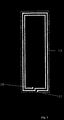
- FIG. 1 a schematic sectional representation of a CIC hearing aid is shown with an antenna according to the invention.
- the hearing aid comprises a custom made shell part 2 which is placed deep in the ear canal. Instead of being custom made the shell part can be either flexible or have a flexible outer portion which allows it to be inserted into the ear.
- 1 is an outline of the external ear of a person.
- the shell part 2 encloses a receiver 5, a signal processing unit 4 and a microphone 3.
- the receiver 5 is arranged with an output orifice (not shown) close to the tympanic membrane 6 in order to deliver a useful audio signal to the user.
- a front plate part 12 is arranged to face the surroundings. In this part a battery drawer 7 with a battery 8 is placed.
- an extractor 9 may be comprised in the front plate.
- Other components may be placed in the shell or associated with the front plate part 12, such as further microphones or connectors for wired contact with other equipment like telephones.
- the hearing aid will comprise a transmission and/or reception circuit in order to feed/receive electromagnetic energy to/from the antenna. This circuit is connected to the antenna and to the signal processing part 4.
- the transmission and/or reception circuit is not shown in the figures, and it may be configured as an independent circuit part or it can be configured as part of the signal processing part 4.
- An antenna 10 is schematically shown.
- the antenna 10 is placed in the area between the battery and the external surface of the frontal plate.
- the antenna 10 is preferably associated the battery drawer 7.
- Fig. 2 displays a loop antenna 13.
- the inductive part of the antenna impedance has to be resonated with an external capacitor (not shown).
- the magnetic field generated by the loop current is the radiating component and dominating in the near field, especially if it is exited by a balanced signal. If operated in unbalanced mode it will also radiate the electric field.
- the antenna is less sensitive to detuning from near by objects.
- the loop has two connections 16 and 11 and can be placed circumferentially with regards to the battery 8.
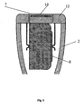
- FIG. 3 a schematic representation of a loop + helix antenna is shown.
- This antenna structure is unbalanced and can be made resonant by itself or in combination with an external capacitor.
- the antenna impedance is adjustable by tapping. Both the H and E fields are radiated from the structure and due to the high end impedance of the helix and compared to the loop antenna, increased sensitivity towards detuning by near by objects must be expected.
- Two connection points 14 and 15 are shown. A loop of two turns and a helix part of two turns is showed but a higher or lower number of turns may be used.
- Fig. 4 discloses a patch antenna 17. Because of the small size of the patch 17 compared to the wavelength the patch 17 can be considered as a capacitor that will require an inductor to be made resonant. The duality between the small loop and the patch is evident. The patch will radiate the electric field from the edges but the tuning inductor will inevitably also add to the radiation pattern with a magnetic contribution. If the patch has a nearby ground plane, only moderate sensitivity to detuning from close by objects will occur.
- the antenna 10 could be either a loop or a patch antenna and in the shown embodiment it is embedded within the material of the battery lid 2. In this way the antenna 10 will lie close to the battery 8, which thereby may function as ground plane and at the same time shield the antenna 10 from receiving radiation from the possible electromagnetic noise from the speaker or other electronic objects in the hearing aid.
- an other embodiment of the invention is schematically shown in sectional view.
- the antenna 10 has an extension, which is wider than the projection of the battery 8 on the battery lid 7.
- the shielding effect of the battery 10 and also the usefulness of the battery as ground plane are not impaired by this, and at the same time an antenna covering a larger area is achieved, whereby further the antenna becomes more effective.
Abstract
Description
- The invention regards hearing aids or other listening devices wherein wireless reception and transmission means are provided. Especially in ITE (in the ear) and CIC (completely in the canal) style hearing aids it is a problem to accommodate antennas for the provision of the wireless transmission.
- In small hearing aids which are to be worn in the ear, the distance between the antenna and the receiver or speaker will be small and as a result, the antenna is likely to pick up unwanted electromagnetic radiation. Inside the hearing aid a microphone and a receiver are placed along with a signal processing device and a battery. The receiver delivers a signal to the user which is perceivable as sound but at the same time the receiver will radiate electromagnetic energy and this is likely to be collected by the antenna and may give rise to either feedback problems or noise. Hearing aids of the above kind are often custom made and the location of electronic devices (the receiver and the signal processing device) within the casing may differ in different hearing aids. As the function of the antenna may depend on the location of nearby electric components it is a problem to not know the exact location of nearby components in advance as this may lead to antennas with widely varying performance in different hearing aids.
- Today wireless communication at frequencies above approximately 1 MHz is not implemented in In-The-Ear (ITE) hearing aids. This will most likely change in the future, and then highly efficient antennas (compared to the available volume) will be needed in order to enable acceptable performance (range, current consumption, etc.). One patent application has been published in this area covering amongst others the use of the pull-out string as an antenna.
US patent 5721783 discloses a hearing aid or audio communication system includes an earpiece that can be hidden in the ear canal, and which communicates wirelessly with a remote processor unit, that enhances audio signals and can be concealed under clothing. The disclosed hearing aid has an antenna arranged in conjunction with the pull out string of the hearing aid. - In prior art document
EP 1326302 an integrated circuit fractal antenna in a hearing aid device is disclosed. The fractal antenna can be incorporated in the hearing device to optimize wireless communication capabilities of the device. -
EP 1013143 discloses a hearing aid comprising a detector for wireless reception of signals and a system comprising said hearing aid. The disclosed hearing aid accommodates an electronic circuit and a battery compartment. A faceplate includes a lid-shaped element which can be moved with respect to the battery compartment. A detector is secured to the lid-shaped element, which detector is embodied so as to be suitable for the wireless reception of signals and conversion thereof to electrical signals. The hearing aid is provided with an electrical connection means which, at least in the closed position of the lid-shaped element, connects the detector to the electronic circuit. The disclosed detector is used for the reception of signals in the infrared light range. As this known receptor works in the infrared light range, where the penetration depth of the signals is poor, it must be placed at an external surface part. - The antenna according to the present invention will be working in the radio frequency range, where the penetration depth of signals is grater, and it cannot in advance easily be determined what will be an advantageous position of the antenna. Further the sensitivity of a radio frequency antenna towards close by electronic components is a problem which has not been dealt with previously.
- It is the object of the invention to provide an antenna for wireless transmission/reception of electromagnetic signals in an ITE or CIC style hearing aid or other listening device, wherein the antenna is not influenced by the varying position of the receiver or other electronic components of the listening device. Further an improved and uniform radiation and reception characteristic for custom made hearing aids is desired.
- This is achieved by the communication device as claimed in claim 1. Accordingly the device is adapted for placement in a users ear and comprises a shell part enclosing an input transducer for receiving an input signal, a signal processing device and an output transducer for providing a signal perceivable as sound, a battery located at a surface part of the shell which is facing away from the head of the user, a transmission and reception circuit for transmission and reception of electromagnetic energy, and whereby an antenna for radiating and/or receiving electromagnetic energy is provided such that it has a first surface turned towards the surroundings and a second surface located in close proximity of the battery.
- By placing the antenna outwardly of the battery the battery may be used as ground, and this is an advantage. Also the position of the battery between the antenna and the other components within the hearing aid will help to ensure, that the antenna does not become de-tuned when the receiver or other components within the shell are fixed at a given position during finishing of custom made hearing aids. Further the battery will provide electromagnetic shielding between the antenna and other parts of the hearing aid circuitry.
- According to the invention the antenna is tuned to radiate and/or receive electromagnetic energy in the frequency range of 50 MHz to 50 GHz. Within this range radio communication is allowed in various bands in most countries without any licence. Examples of such bands are the ISM bands. This also means that there is likely to be some noise in these frequency bands, and this is a further reason for the antenna to be effective. The antenna is usable for either digital or analog coding of signals.
- Preferably the antenna is shaped as a part of a flexprint. This construction is advantageous because it is possible to use the flexibility of the flexprint to pride connections across possible moving parts, like from the battery lid to the rest of the hearing aid.
- In an embodiment of the invention the antenna is embedded in material externally of the battery. Embedding the antenna in material will aid to protect the antenna and at the same time minimize the space taken up by the antenna. The embedding may be accomplished by over-molding a flexprint-antenna or a solid metal part. It could also be realized by providing a surface metalization trace on a polymer part of the antenna and then overmolding or covering the surface trace in some other way.
- In a further embodiment the antenna covers a surface area of the shell which is wider than the projection of the battery onto the faceplate surface. In most ITE hearing aids the battery lid has the same dimensions as the battery. This is a serious limitation for the antenna, and this can be overcome by allowing the antenna to extend sideways beyond the size of the battery and the battery lid. The antenna cannot however be allowed to extend beyond the overall size of the hearing aid.
- In an embodiment the antenna comprises a loop, which is usable also as a charging loop for a battery. In modern hearing aids rechargeable batteries are becoming more common, and in order to charge the batteries the hearing aid is placed in a strong varying magnetic field, which will generate a current in a an electric loop or coil inside the hearing aid. It has been discovered that the antenna can be used as the induction loop on the secondary side of such a charging device.
-
-
Fig. 1 is a side view of a schematic representation of an ITE hearing aid with an antenna according to the invention, -
Fig. 2 is a schematic representation of an antenna according to the invention, -
Fig. 3 is a schematic representation of an antenna according to the invention, -
Fig. 4 is a schematic representation of an antenna according to the invention, -
Fig. 5 is a schematic representation of an antenna in side sectional view, -
Fig. 6 is a schematic representation of an antenna in side sectional view. - Initially it is worth noting that we are dealing with small antennas, meaning that the wavelength is much larger than the physical size of the antenna and therefore the antenna has a narrow bandwidth (high quality factors) and low efficiency (small radiation resistance compared to the loss resistance). If high currents are dominating, the structure will mainly radiate the magnetic field and vice versa: if high voltages are present, a dominating electric field must be expected.
- In
fig. 1 a schematic sectional representation of a CIC hearing aid is shown with an antenna according to the invention. The hearing aid comprises a custom madeshell part 2 which is placed deep in the ear canal. Instead of being custom made the shell part can be either flexible or have a flexible outer portion which allows it to be inserted into the ear. 1 is an outline of the external ear of a person. Theshell part 2 encloses a receiver 5, asignal processing unit 4 and a microphone 3. The receiver 5 is arranged with an output orifice (not shown) close to the tympanic membrane 6 in order to deliver a useful audio signal to the user. Afront plate part 12 is arranged to face the surroundings. In this part abattery drawer 7 with abattery 8 is placed. Also anextractor 9 may be comprised in the front plate. Other components may be placed in the shell or associated with thefront plate part 12, such as further microphones or connectors for wired contact with other equipment like telephones. Also the hearing aid will comprise a transmission and/or reception circuit in order to feed/receive electromagnetic energy to/from the antenna. This circuit is connected to the antenna and to thesignal processing part 4. The transmission and/or reception circuit is not shown in the figures, and it may be configured as an independent circuit part or it can be configured as part of thesignal processing part 4. - An
antenna 10 is schematically shown. Theantenna 10 is placed in the area between the battery and the external surface of the frontal plate. Theantenna 10 is preferably associated thebattery drawer 7. -
Fig. 2 displays aloop antenna 13. The inductive part of the antenna impedance has to be resonated with an external capacitor (not shown). The magnetic field generated by the loop current is the radiating component and dominating in the near field, especially if it is exited by a balanced signal. If operated in unbalanced mode it will also radiate the electric field. The antenna is less sensitive to detuning from near by objects. The loop has twoconnections battery 8. - In
fig. 3 a schematic representation of a loop + helix antenna is shown. This antenna structure is unbalanced and can be made resonant by itself or in combination with an external capacitor. The antenna impedance is adjustable by tapping. Both the H and E fields are radiated from the structure and due to the high end impedance of the helix and compared to the loop antenna, increased sensitivity towards detuning by near by objects must be expected. Two connection points 14 and 15 are shown. A loop of two turns and a helix part of two turns is showed but a higher or lower number of turns may be used. -
Fig. 4 discloses apatch antenna 17. Because of the small size of thepatch 17 compared to the wavelength thepatch 17 can be considered as a capacitor that will require an inductor to be made resonant. The duality between the small loop and the patch is evident. The patch will radiate the electric field from the edges but the tuning inductor will inevitably also add to the radiation pattern with a magnetic contribution. If the patch has a nearby ground plane, only moderate sensitivity to detuning from close by objects will occur. - In
fig. 5 an enlarged side sectional view of an embodiment of the invention is schematically shown. Theantenna 10 could be either a loop or a patch antenna and in the shown embodiment it is embedded within the material of thebattery lid 2. In this way theantenna 10 will lie close to thebattery 8, which thereby may function as ground plane and at the same time shield theantenna 10 from receiving radiation from the possible electromagnetic noise from the speaker or other electronic objects in the hearing aid. - In
fig. 6 , an other embodiment of the invention is schematically shown in sectional view. Here theantenna 10 has an extension, which is wider than the projection of thebattery 8 on thebattery lid 7. The shielding effect of thebattery 10 and also the usefulness of the battery as ground plane are not impaired by this, and at the same time an antenna covering a larger area is achieved, whereby further the antenna becomes more effective.
Claims (7)
- Communication device which is adapted for placement in a users ear and comprises a shell part enclosing an input transducer for receiving an input signal, a signal processing device and an output transducer for providing a signal perceivable as sound, a battery located at a surface part of the shell which is facing away from the head of the user, a transmission and reception circuit for transmission and/or reception of electromagnetic energy, and whereby a patch or loop and/or helix antenna or radiating and/or receiving electromagnetic energy is provided, and wherein the antenna is placed in the area between the battery and the surface part of the shell such that it has a first surface turned towards the surroundings and a second surface located in close proximity of the battery, and wherein the antenna is tuned to radiate and/or receive electromagnetic energy in the frequency range of 50 MHz to 50 GHz.
- Communication device as claimed in claim 1, wherein the antenna is shaped as a part of a flexprint.
- Communication device as claimed in claim 1 or 2, wherein the antenna is embedded in material externally of the battery.
- Communication device as claimed in claim 3, wherein the antenna is a metal part.
- Communication device as claimed in any one of claims 1-4, wherein the antenna is manufactured by deposition of metal material on surface parts of the faceplate and/or battery drawer.
- Communication device as claimed in any one of claims 1-5, wherein the antenna covers a surface area of the shell which is wider than the projection of the battery onto the faceplate surface.
- Communication device as claimed in any one of claims 1-6, wherein the antenna comprises a loop, which is usable also as a charging loop for a battery.
Applications Claiming Priority (2)
| Application Number | Priority Date | Filing Date | Title |
|---|---|---|---|
| DKPA200400259 | 2004-02-19 | ||
| EP05706773A EP1719384B1 (en) | 2004-02-19 | 2005-02-16 | Hearing aid with antenna for reception and transmission of electromagnetic signals and shielding battery |
Related Parent Applications (2)
| Application Number | Title | Priority Date | Filing Date |
|---|---|---|---|
| EP05706773 Previously-Filed-Application | 2005-02-16 | ||
| EP05706773.8 Division | 2005-02-16 |
Publications (2)
| Publication Number | Publication Date |
|---|---|
| EP2285138A1 true EP2285138A1 (en) | 2011-02-16 |
| EP2285138B1 EP2285138B1 (en) | 2013-04-03 |
Family
ID=34878001
Family Applications (2)
| Application Number | Title | Priority Date | Filing Date |
|---|---|---|---|
| EP05706773A Active EP1719384B1 (en) | 2004-02-19 | 2005-02-16 | Hearing aid with antenna for reception and transmission of electromagnetic signals and shielding battery |
| EP10177543A Active EP2285138B1 (en) | 2004-02-19 | 2005-02-16 | Hearing aid with antenna for reception and transmission of electromagnetic signals |
Family Applications Before (1)
| Application Number | Title | Priority Date | Filing Date |
|---|---|---|---|
| EP05706773A Active EP1719384B1 (en) | 2004-02-19 | 2005-02-16 | Hearing aid with antenna for reception and transmission of electromagnetic signals and shielding battery |
Country Status (7)
| Country | Link |
|---|---|
| US (5) | US7742614B2 (en) |
| EP (2) | EP1719384B1 (en) |
| CN (1) | CN1934902B (en) |
| AT (1) | ATE508590T1 (en) |
| DE (1) | DE602005027813D1 (en) |
| DK (2) | DK2285138T3 (en) |
| WO (1) | WO2005081583A1 (en) |
Cited By (5)
| Publication number | Priority date | Publication date | Assignee | Title |
|---|---|---|---|---|
| CN103515694A (en) * | 2012-06-25 | 2014-01-15 | Gn瑞声达A/S | Antenna system for a wearable computing device |
| WO2014090420A1 (en) * | 2012-12-12 | 2014-06-19 | Siemens Medical Instruments Pte. Ltd. | Folded dipole for hearing aid devices |
| EP3110175A1 (en) * | 2015-06-24 | 2016-12-28 | Oticon A/s | Hearing aid including antenna unit embedded in battery drawer |
| EP3780267A1 (en) | 2019-08-16 | 2021-02-17 | Sonova AG | Hearing device and method of manufacturing the same |
| US11490215B2 (en) | 2020-02-06 | 2022-11-01 | Sivantos Pte. Ltd. | Hearing aid |
Families Citing this family (91)
| Publication number | Priority date | Publication date | Assignee | Title |
|---|---|---|---|---|
| US7593538B2 (en) * | 2005-03-28 | 2009-09-22 | Starkey Laboratories, Inc. | Antennas for hearing aids |
| DE102005046169A1 (en) * | 2005-09-27 | 2007-04-05 | Siemens Audiologische Technik Gmbh | Hearing aid with an antenna |
| US20070080889A1 (en) * | 2005-10-11 | 2007-04-12 | Gennum Corporation | Electrically small multi-level loop antenna on flex for low power wireless hearing aid system |
| US8724835B2 (en) | 2005-12-19 | 2014-05-13 | Nxp B.V. | Radio receiver, radio transmitter, and hearing aid |
| EP1821571A1 (en) | 2006-02-15 | 2007-08-22 | Oticon A/S | Loop antenna for in the ear audio device |
| US7548211B2 (en) | 2006-03-30 | 2009-06-16 | Phonak Ag | Wireless audio signal receiver device for a hearing instrument |
| DK2257079T3 (en) * | 2006-03-30 | 2012-03-26 | Phonak Ag | Wireless audio signal receiver for a hearing aid |
| DE102006049469B4 (en) * | 2006-10-16 | 2010-04-15 | Siemens Audiologische Technik Gmbh | Hearing aid with live metal strap |
| US8098858B2 (en) | 2006-10-16 | 2012-01-17 | Siemens Audiologische Technik Gmbh | Hearing device with current-conducting metal arm |
| US8934984B2 (en) | 2007-05-31 | 2015-01-13 | Cochlear Limited | Behind-the-ear (BTE) prosthetic device with antenna |
| DE102007051307B4 (en) * | 2007-10-26 | 2011-02-17 | Siemens Medical Instruments Pte. Ltd. | Hearing device with use of an inductive switching regulator as a radio transmitter |
| ES2443918T5 (en) * | 2007-12-27 | 2017-06-06 | Oticon A/S | Hearing device and procedure for receiving and / or sending wireless data |
| US7652628B2 (en) | 2008-03-13 | 2010-01-26 | Sony Ericsson Mobile Communications Ab | Antenna for use in earphone and earphone with integrated antenna |
| DE102008023352B4 (en) * | 2008-05-13 | 2014-02-06 | Siemens Medical Instruments Pte. Ltd. | hearing Aid |
| US8494197B2 (en) * | 2008-12-19 | 2013-07-23 | Starkey Laboratories, Inc. | Antennas for custom fit hearing assistance devices |
| US8699733B2 (en) | 2008-12-19 | 2014-04-15 | Starkey Laboratories, Inc. | Parallel antennas for standard fit hearing assistance devices |
| US8737658B2 (en) * | 2008-12-19 | 2014-05-27 | Starkey Laboratories, Inc. | Three dimensional substrate for hearing assistance devices |
| US10142747B2 (en) | 2008-12-19 | 2018-11-27 | Starkey Laboratories, Inc. | Three dimensional substrate for hearing assistance devices |
| US8565457B2 (en) | 2008-12-19 | 2013-10-22 | Starkey Laboratories, Inc. | Antennas for standard fit hearing assistance devices |
| EP2207238B1 (en) * | 2009-01-08 | 2016-11-09 | Oticon A/S | Small size, low power device |
| DE102010022323A1 (en) * | 2010-06-01 | 2011-12-01 | Siemens Medical Instruments Pte. Ltd. | Deep-ear-canal hearing instrument |
| EP2725655B1 (en) | 2010-10-12 | 2021-07-07 | GN Hearing A/S | A behind-the-ear hearing aid with an improved antenna |
| DK2458675T3 (en) | 2010-10-12 | 2018-01-22 | Gn Hearing As | Hearing aid with antenna |
| WO2012059302A2 (en) | 2010-10-12 | 2012-05-10 | Gn Resound A/S | An antenna device |
| JP5757111B2 (en) * | 2010-11-19 | 2015-07-29 | ソニー株式会社 | Secondary battery cell, battery pack and power consuming equipment |
| US20130188803A1 (en) * | 2012-01-20 | 2013-07-25 | Qualcomm Incorporated | Earpiece |
| US20130343586A1 (en) * | 2012-06-25 | 2013-12-26 | Gn Resound A/S | Hearing aid having a slot antenna |
| DK2723101T3 (en) | 2012-07-06 | 2019-02-04 | Gn Hearing As | Rear-ear hearing system with balanced antenna |
| US9554219B2 (en) | 2012-07-06 | 2017-01-24 | Gn Resound A/S | BTE hearing aid having a balanced antenna |
| DK201270411A (en) | 2012-07-06 | 2014-01-07 | Gn Resound As | BTE hearing aid having two driven antennas |
| DK201270410A (en) * | 2012-07-06 | 2014-01-07 | Gn Resound As | BTE hearing aid with an antenna partition plane |
| US9374650B2 (en) | 2012-07-17 | 2016-06-21 | Starkey Laboratories, Inc. | System and method for embedding conductive traces into hearing assistance device housings |
| EP2733962B1 (en) | 2012-11-19 | 2016-11-09 | GN Resound A/S | A hearing aid having a near field resonant parasitic element |
| US9237404B2 (en) | 2012-12-28 | 2016-01-12 | Gn Resound A/S | Dipole antenna for a hearing aid |
| EP2765650A1 (en) * | 2013-02-08 | 2014-08-13 | Nxp B.V. | Hearing aid antenna |
| US10743116B2 (en) | 2013-04-30 | 2020-08-11 | Starkey Laboratories, Inc. | Small loop antenna with shorting conductors for hearing assistance devices |
| WO2014190086A2 (en) * | 2013-05-22 | 2014-11-27 | Starkey Laboratories, Inc. | Augmented reality multisensory display device incorporated with hearing assistance device features |
| DE102013210689B3 (en) * | 2013-06-07 | 2014-10-02 | Siemens Medical Instruments Pte. Ltd. | Antenna device for hearing instruments |
| US10985447B2 (en) | 2013-08-02 | 2021-04-20 | Gn Hearing A/S | Antenna device |
| EP2835863B1 (en) | 2013-08-09 | 2019-12-11 | Oticon A/s | Hearing device with RF antenna |
| US9883295B2 (en) | 2013-11-11 | 2018-01-30 | Gn Hearing A/S | Hearing aid with an antenna |
| US9237405B2 (en) | 2013-11-11 | 2016-01-12 | Gn Resound A/S | Hearing aid with an antenna |
| US9686621B2 (en) | 2013-11-11 | 2017-06-20 | Gn Hearing A/S | Hearing aid with an antenna |
| US9408003B2 (en) | 2013-11-11 | 2016-08-02 | Gn Resound A/S | Hearing aid with an antenna |
| US10595138B2 (en) | 2014-08-15 | 2020-03-17 | Gn Hearing A/S | Hearing aid with an antenna |
| DK3038204T3 (en) | 2014-12-22 | 2021-06-21 | Oticon As | ANTENNA DEVICE FOR HEARING AID |
| US9641927B2 (en) * | 2015-01-12 | 2017-05-02 | Qualcomm Technologies International, Ltd. | Antennas suitable for wireless earphones |
| US10165376B2 (en) * | 2015-03-31 | 2018-12-25 | Starkey Laboratories, Inc. | Non-contact antenna feed |
| US20160330552A1 (en) | 2015-05-07 | 2016-11-10 | Starkey Laboratories, Inc. | Hearing aid bowtie antenna optimized for ear to ear communications |
| US9661426B2 (en) | 2015-06-22 | 2017-05-23 | Gn Hearing A/S | Hearing aid having combined antennas |
| EP3116238B1 (en) * | 2015-07-08 | 2020-01-29 | Oticon A/s | Spacer and hearing device comprising it |
| US9609443B2 (en) * | 2015-07-21 | 2017-03-28 | Gn Hearing A/S | In-the-ear hearing aid having combined antennas |
| EP3122071B1 (en) * | 2015-07-21 | 2018-08-29 | GN Hearing A/S | An in-the-ear hearing aid having combined antennas |
| DK179124B1 (en) * | 2015-07-21 | 2017-11-20 | Gn Hearing As | I-EAR HEARING WITH COMBINED ANTENNA |
| US10257624B2 (en) * | 2015-08-17 | 2019-04-09 | Starkey Laboratories, Inc. | Hearing aid wireless antenna molded into the device shell |
| US9950163B2 (en) * | 2015-08-27 | 2018-04-24 | Cochler Limited | Configuration of hearing device components |
| EP3148219B1 (en) * | 2015-09-28 | 2020-12-02 | Oticon A/s | Hearing device |
| DK201570757A1 (en) * | 2015-11-25 | 2017-06-12 | Gn Hearing As | Ite hearing aid with improved wireless communication |
| US10440483B2 (en) * | 2015-11-25 | 2019-10-08 | Gn Hearing A/S | Hearing aid with improved wireless communication |
| US10122090B2 (en) | 2015-12-21 | 2018-11-06 | Google Llc | Anntena configurations for wireless devices |
| DE102016200831A1 (en) * | 2016-01-21 | 2017-07-27 | Sivantos Pte. Ltd. | hearing Aid |
| WO2018024392A1 (en) * | 2016-08-01 | 2018-02-08 | Sivantos Pte. Ltd. | Hearing aid comprising an rf antenna |
| WO2017153020A1 (en) * | 2016-08-01 | 2017-09-14 | Sivantos Pte. Ltd. | Hearing aid comprising an rf antenna |
| US10051388B2 (en) | 2016-09-21 | 2018-08-14 | Starkey Laboratories, Inc. | Radio frequency antenna for an in-the-ear hearing device |
| WO2018059688A1 (en) * | 2016-09-29 | 2018-04-05 | Sonova Ag | A hearing device and a method for manufacturing thereof |
| US10297910B2 (en) | 2016-10-21 | 2019-05-21 | Starkey Laboratories, Inc. | Hearing device with bowtie antenna optimized for specific band |
| US10477329B2 (en) | 2016-10-27 | 2019-11-12 | Starkey Laboratories, Inc. | Antenna structure for hearing devices |
| DE102017209813B3 (en) | 2017-06-09 | 2018-09-06 | Sivantos Pte. Ltd. | Hearing aid, in particular behind-the-ear hearing aid |
| KR102075779B1 (en) * | 2017-08-18 | 2020-02-11 | 주식회사 아모텍 | Ring type antenna and earphone having the same |
| DK3471198T3 (en) * | 2017-10-16 | 2021-01-11 | Widex As | ANTENNA FOR A HEARING SUPPORT DEVICE |
| EP3471200B1 (en) | 2017-10-16 | 2020-04-01 | Widex A/S | Antenna for a hearing assistance device |
| EP3499913B1 (en) * | 2017-12-14 | 2020-12-02 | GN Hearing A/S | Multiple arm dipole antenna for hearing instrument |
| DK3506656T3 (en) | 2017-12-29 | 2023-05-01 | Gn Hearing As | HEARING INSTRUMENT COMPRISING A PARASITIC BATTERY ANTENNA ELEMENT |
| WO2019130843A1 (en) * | 2017-12-29 | 2019-07-04 | ソニー株式会社 | Acoustic output device |
| EP4013071A1 (en) | 2018-02-21 | 2022-06-15 | Oticon A/s | Hearing aid device having an antenna |
| CN112313833A (en) | 2018-06-25 | 2021-02-02 | 索诺瓦公司 | Transmission system for body-worn electronic devices |
| US10547957B1 (en) | 2018-09-27 | 2020-01-28 | Starkey Laboratories, Inc. | Hearing aid antenna for high-frequency data communication |
| US11031680B2 (en) * | 2018-10-02 | 2021-06-08 | Nxp B.V. | Near-field electromagnetic induction (NFEMI) antenna |
| EP3661230A1 (en) | 2018-11-30 | 2020-06-03 | GN Hearing A/S | Hearing device with integrated magnetic induction coil and rf antenna |
| US10805707B2 (en) * | 2019-01-04 | 2020-10-13 | Bose Corporation | Systems and methods for unconstrained battery spring tab assemblies for in-ear headphone |
| US11355834B2 (en) * | 2019-02-06 | 2022-06-07 | Starkey Laboratories, Inc. | Ear-worn electronic device incorporating an antenna substrate comprising a dielectric gel or liquid |
| US11140496B2 (en) * | 2019-02-26 | 2021-10-05 | Starkey Laboratories, Inc. | Ear-worn electronic device incorporating an integrated battery/antenna module |
| US10841716B2 (en) * | 2019-03-29 | 2020-11-17 | Sonova Ag | Hearing device with two-half loop antenna |
| US11122376B2 (en) * | 2019-04-01 | 2021-09-14 | Starkey Laboratories, Inc. | Ear-worn electronic device incorporating magnetically coupled feed for an antenna |
| US10819024B1 (en) | 2019-04-10 | 2020-10-27 | Nxp B.V. | Combination near-field and far-field antenna |
| US11211694B2 (en) | 2019-07-08 | 2021-12-28 | Nxp B.V. | Near-field wireless device |
| WO2021041843A1 (en) * | 2019-08-30 | 2021-03-04 | Starkey Laboratories, Inc. | Hearing instruments with receiver positioned posterior to battery |
| US11245989B2 (en) * | 2019-12-11 | 2022-02-08 | Gn Hearing A/S | Hearing aid for placement in a user's ear canal |
| CN113207074B (en) * | 2019-12-11 | 2023-01-20 | 大北欧听力公司 | Hearing aid for placement in the ear canal of a user |
| EP3836558A1 (en) * | 2019-12-11 | 2021-06-16 | GN Hearing A/S | A hearing aid for placement in a user´s ear canal |
| WO2021115790A1 (en) * | 2019-12-12 | 2021-06-17 | Widex A/S | Hearing assistive device having a rechargeable battery |
Citations (7)
| Publication number | Priority date | Publication date | Assignee | Title |
|---|---|---|---|---|
| WO1992013430A1 (en) * | 1991-01-17 | 1992-08-06 | Adelman Roger A | Improved hearing apparatus |
| WO1996041498A1 (en) * | 1995-06-07 | 1996-12-19 | Anderson James C | Hearing aid with wireless remote processor |
| US5734976A (en) * | 1994-03-07 | 1998-03-31 | Phonak Communications Ag | Micro-receiver for receiving a high frequency frequency-modulated or phase-modulated signal |
| EP1013143A1 (en) | 1998-03-19 | 2000-06-28 | Beltone Netherlands B.V. | A hearing aid comprising a detector for wireless reception of signals and a system comprising said hearing aid |
| EP1250026A1 (en) * | 2001-04-11 | 2002-10-16 | Phonic Ear, Inc. | Short range data transfer for communication devices |
| EP1326302A2 (en) | 2001-12-28 | 2003-07-09 | Zarlink Semiconductor (U.S.) Inc. | Integrated circuit fractal antenna in a hearing aid device |
| EP1389035A2 (en) * | 2002-08-08 | 2004-02-11 | Siemens Audiologische Technik GmbH | Wireless programmable hearing aid |
Family Cites Families (18)
| Publication number | Priority date | Publication date | Assignee | Title |
|---|---|---|---|---|
| DE9415594U1 (en) | 1994-09-29 | 1996-02-08 | Toepholm & Westermann | Hearing aid |
| US5020136A (en) | 1986-04-21 | 1991-05-28 | Motorola, Inc. | Battery pack antenna suitable for use with two-way portable transceivers |
| JPH0567910A (en) | 1991-09-06 | 1993-03-19 | Nippon Telegr & Teleph Corp <Ntt> | Portable radio equipment |
| US5349362A (en) * | 1992-06-19 | 1994-09-20 | Forbes Mark M | Concealed antenna applying electrically-shortened elements and durable construction |
| US6473511B1 (en) * | 1996-03-14 | 2002-10-29 | Sarnoff Corporation | Disposable hearing aid with integral power source |
| DK42197A (en) * | 1997-04-15 | 1998-10-16 | Toepholm & Westermann | Compact modulated in-ear hearing aid |
| US6473512B1 (en) | 1997-12-18 | 2002-10-29 | Softear Technologies, L.L.C. | Apparatus and method for a custom soft-solid hearing aid |
| JPH11308680A (en) | 1998-04-21 | 1999-11-05 | Hiromasa Kobayashi | Ear-adaptor type handset |
| US6137889A (en) * | 1998-05-27 | 2000-10-24 | Insonus Medical, Inc. | Direct tympanic membrane excitation via vibrationally conductive assembly |
| US6694034B2 (en) * | 2000-01-07 | 2004-02-17 | Etymotic Research, Inc. | Transmission detection and switch system for hearing improvement applications |
| US7334734B2 (en) * | 2000-01-27 | 2008-02-26 | Hitachi Maxwell, Ltd. | Non-contact IC module |
| JP2001217638A (en) | 2000-01-31 | 2001-08-10 | Hitachi Kokusai Electric Inc | Antenna for card-type radio equipment |
| GB0004669D0 (en) | 2000-02-28 | 2000-04-19 | Robinson John W | Mobile phone cae (microwave safe) |
| US6597320B2 (en) * | 2000-09-11 | 2003-07-22 | Nippon Soken, Inc. | Antenna for portable radio communication device and method of transmitting radio signal |
| US6498455B2 (en) * | 2001-02-22 | 2002-12-24 | Gary Skuro | Wireless battery charging system for existing hearing aids using a dynamic battery and a charging processor unit |
| DE10115896C2 (en) * | 2001-03-30 | 2003-12-24 | Siemens Audiologische Technik | Transmitter and / or receiver unit, which can be releasably connected to a hearing aid, and a programmable hearing aid |
| US6786860B2 (en) * | 2001-10-03 | 2004-09-07 | Advanced Bionics Corporation | Hearing aid design |
| US20050099341A1 (en) | 2003-11-12 | 2005-05-12 | Gennum Corporation | Antenna for a wireless hearing aid system |
-
2005
- 2005-02-16 DE DE602005027813T patent/DE602005027813D1/en active Active
- 2005-02-16 DK DK10177543.5T patent/DK2285138T3/en active
- 2005-02-16 EP EP05706773A patent/EP1719384B1/en active Active
- 2005-02-16 WO PCT/DK2005/000100 patent/WO2005081583A1/en active Application Filing
- 2005-02-16 EP EP10177543A patent/EP2285138B1/en active Active
- 2005-02-16 DK DK05706773.8T patent/DK1719384T3/en active
- 2005-02-16 CN CN2005800053883A patent/CN1934902B/en active Active
- 2005-02-16 AT AT05706773T patent/ATE508590T1/en not_active IP Right Cessation
- 2005-02-16 US US10/589,759 patent/US7742614B2/en active Active
-
2010
- 2010-04-23 US US12/766,700 patent/US8675902B2/en active Active
-
2013
- 2013-12-11 US US14/103,469 patent/US8995699B2/en active Active
-
2015
- 2015-02-20 US US14/627,723 patent/US9602933B2/en active Active
-
2017
- 2017-02-08 US US15/427,527 patent/US10257627B2/en active Active
Patent Citations (8)
| Publication number | Priority date | Publication date | Assignee | Title |
|---|---|---|---|---|
| WO1992013430A1 (en) * | 1991-01-17 | 1992-08-06 | Adelman Roger A | Improved hearing apparatus |
| US5734976A (en) * | 1994-03-07 | 1998-03-31 | Phonak Communications Ag | Micro-receiver for receiving a high frequency frequency-modulated or phase-modulated signal |
| WO1996041498A1 (en) * | 1995-06-07 | 1996-12-19 | Anderson James C | Hearing aid with wireless remote processor |
| US5721783A (en) | 1995-06-07 | 1998-02-24 | Anderson; James C. | Hearing aid with wireless remote processor |
| EP1013143A1 (en) | 1998-03-19 | 2000-06-28 | Beltone Netherlands B.V. | A hearing aid comprising a detector for wireless reception of signals and a system comprising said hearing aid |
| EP1250026A1 (en) * | 2001-04-11 | 2002-10-16 | Phonic Ear, Inc. | Short range data transfer for communication devices |
| EP1326302A2 (en) | 2001-12-28 | 2003-07-09 | Zarlink Semiconductor (U.S.) Inc. | Integrated circuit fractal antenna in a hearing aid device |
| EP1389035A2 (en) * | 2002-08-08 | 2004-02-11 | Siemens Audiologische Technik GmbH | Wireless programmable hearing aid |
Cited By (15)
| Publication number | Priority date | Publication date | Assignee | Title |
|---|---|---|---|---|
| CN103515694A (en) * | 2012-06-25 | 2014-01-15 | Gn瑞声达A/S | Antenna system for a wearable computing device |
| EP2932560B1 (en) | 2012-12-12 | 2017-08-23 | Sivantos Pte. Ltd. | Folded dipol for hearing aid |
| WO2014090420A1 (en) * | 2012-12-12 | 2014-06-19 | Siemens Medical Instruments Pte. Ltd. | Folded dipole for hearing aid devices |
| US20150296312A1 (en) * | 2012-12-12 | 2015-10-15 | Sivantos Pte. Ltd. | Hearing aid device having a folded dipole |
| US9888327B2 (en) * | 2012-12-12 | 2018-02-06 | Sivantos Pte. Ltd. | Hearing aid device having a folded dipole |
| EP3110175A1 (en) * | 2015-06-24 | 2016-12-28 | Oticon A/s | Hearing aid including antenna unit embedded in battery drawer |
| CN106303871A (en) * | 2015-06-24 | 2017-01-04 | 奥迪康有限公司 | Hearing devices including antenna element |
| US9973864B2 (en) | 2015-06-24 | 2018-05-15 | Oticon A/S | Hearing device including antenna unit |
| US10009697B2 (en) | 2015-06-24 | 2018-06-26 | Oticon A/S | Hearing device including antenna unit |
| US10313807B2 (en) | 2015-06-24 | 2019-06-04 | Oticon A/S | Hearing device including antenna unit |
| US10659892B2 (en) | 2015-06-24 | 2020-05-19 | Oticon A/S | Hearing device including antenna unit |
| CN106303871B (en) * | 2015-06-24 | 2020-07-14 | 奥迪康有限公司 | Hearing device comprising an antenna unit |
| US10993053B2 (en) | 2015-06-24 | 2021-04-27 | Oticon A/S | Hearing device including antenna unit |
| EP3780267A1 (en) | 2019-08-16 | 2021-02-17 | Sonova AG | Hearing device and method of manufacturing the same |
| US11490215B2 (en) | 2020-02-06 | 2022-11-01 | Sivantos Pte. Ltd. | Hearing aid |
Also Published As
| Publication number | Publication date |
|---|---|
| US8675902B2 (en) | 2014-03-18 |
| EP1719384A1 (en) | 2006-11-08 |
| US8995699B2 (en) | 2015-03-31 |
| EP1719384B1 (en) | 2011-05-04 |
| ATE508590T1 (en) | 2011-05-15 |
| US20080056520A1 (en) | 2008-03-06 |
| DE602005027813D1 (en) | 2011-06-16 |
| WO2005081583A1 (en) | 2005-09-01 |
| CN1934902A (en) | 2007-03-21 |
| EP2285138B1 (en) | 2013-04-03 |
| US7742614B2 (en) | 2010-06-22 |
| US20100202639A1 (en) | 2010-08-12 |
| DK1719384T3 (en) | 2011-07-11 |
| CN1934902B (en) | 2012-05-30 |
| WO2005081583A9 (en) | 2006-12-14 |
| US20150163603A1 (en) | 2015-06-11 |
| US20140169604A1 (en) | 2014-06-19 |
| US10257627B2 (en) | 2019-04-09 |
| US9602933B2 (en) | 2017-03-21 |
| US20170150280A1 (en) | 2017-05-25 |
| DK2285138T3 (en) | 2013-07-01 |
Similar Documents
| Publication | Publication Date | Title |
|---|---|---|
| US10257627B2 (en) | Hearing aid with antenna for reception and transmission of electromagnetic signals | |
| DK2476266T3 (en) | Hearing Aid with wireless battery charging capacity | |
| EP3531718B1 (en) | Hearing aid device having an antenna | |
| CN109845295B (en) | Hearing aid and hearing aid device | |
| JP2018519739A (en) | Hearing aid with composite antenna | |
| EP2750409B1 (en) | A dipole antenna for a hearing aid | |
| US11653159B2 (en) | Hearing instrument comprising a battery antenna | |
| EP3629600A1 (en) | Hearing device with antenna extending from the hearing device | |
| JP6691192B2 (en) | hearing aid | |
| CN110891234A (en) | Hearing aid with automatic antenna tuning | |
| US11553292B2 (en) | In-the-ear hearing device | |
| US11570559B2 (en) | Hearing instrument comprising a parasitic battery antenna element | |
| US10869143B2 (en) | Hearing instrument comprising a parasitic battery antenna element |
Legal Events
| Date | Code | Title | Description |
|---|---|---|---|
| PUAI | Public reference made under article 153(3) epc to a published international application that has entered the european phase |
Free format text: ORIGINAL CODE: 0009012 |
|
| AC | Divisional application: reference to earlier application |
Ref document number: 1719384 Country of ref document: EP Kind code of ref document: P |
|
| AK | Designated contracting states |
Kind code of ref document: A1 Designated state(s): AT BE BG CH CY CZ DE DK EE ES FI FR GB GR HU IE IS IT LI LT LU MC NL PL PT RO SE SI SK TR |
|
| 17P | Request for examination filed |
Effective date: 20110816 |
|
| 17Q | First examination report despatched |
Effective date: 20110922 |
|
| GRAP | Despatch of communication of intention to grant a patent |
Free format text: ORIGINAL CODE: EPIDOSNIGR1 |
|
| GRAS | Grant fee paid |
Free format text: ORIGINAL CODE: EPIDOSNIGR3 |
|
| GRAA | (expected) grant |
Free format text: ORIGINAL CODE: 0009210 |
|
| AC | Divisional application: reference to earlier application |
Ref document number: 1719384 Country of ref document: EP Kind code of ref document: P |
|
| AK | Designated contracting states |
Kind code of ref document: B1 Designated state(s): AT BE BG CH CY CZ DE DK EE ES FI FR GB GR HU IE IS IT LI LT LU MC NL PL PT RO SE SI SK TR |
|
| REG | Reference to a national code |
Ref country code: GB Ref legal event code: FG4D |
|
| REG | Reference to a national code |
Ref country code: CH Ref legal event code: EP Ref country code: AT Ref legal event code: REF Ref document number: 605377 Country of ref document: AT Kind code of ref document: T Effective date: 20130415 |
|
| REG | Reference to a national code |
Ref country code: IE Ref legal event code: FG4D |
|
| REG | Reference to a national code |
Ref country code: DE Ref legal event code: R096 Ref document number: 602005038936 Country of ref document: DE Effective date: 20130529 |
|
| REG | Reference to a national code |
Ref country code: DK Ref legal event code: T3 |
|
| REG | Reference to a national code |
Ref country code: AT Ref legal event code: MK05 Ref document number: 605377 Country of ref document: AT Kind code of ref document: T Effective date: 20130403 |
|
| PG25 | Lapsed in a contracting state [announced via postgrant information from national office to epo] |
Ref country code: SI Free format text: LAPSE BECAUSE OF FAILURE TO SUBMIT A TRANSLATION OF THE DESCRIPTION OR TO PAY THE FEE WITHIN THE PRESCRIBED TIME-LIMIT Effective date: 20130403 |
|
| REG | Reference to a national code |
Ref country code: NL Ref legal event code: VDEP Effective date: 20130403 |
|
| REG | Reference to a national code |
Ref country code: LT Ref legal event code: MG4D |
|
| PG25 | Lapsed in a contracting state [announced via postgrant information from national office to epo] |
Ref country code: GR Free format text: LAPSE BECAUSE OF FAILURE TO SUBMIT A TRANSLATION OF THE DESCRIPTION OR TO PAY THE FEE WITHIN THE PRESCRIBED TIME-LIMIT Effective date: 20130704 Ref country code: PT Free format text: LAPSE BECAUSE OF FAILURE TO SUBMIT A TRANSLATION OF THE DESCRIPTION OR TO PAY THE FEE WITHIN THE PRESCRIBED TIME-LIMIT Effective date: 20130805 Ref country code: IS Free format text: LAPSE BECAUSE OF FAILURE TO SUBMIT A TRANSLATION OF THE DESCRIPTION OR TO PAY THE FEE WITHIN THE PRESCRIBED TIME-LIMIT Effective date: 20130803 Ref country code: BE Free format text: LAPSE BECAUSE OF FAILURE TO SUBMIT A TRANSLATION OF THE DESCRIPTION OR TO PAY THE FEE WITHIN THE PRESCRIBED TIME-LIMIT Effective date: 20130403 Ref country code: SE Free format text: LAPSE BECAUSE OF FAILURE TO SUBMIT A TRANSLATION OF THE DESCRIPTION OR TO PAY THE FEE WITHIN THE PRESCRIBED TIME-LIMIT Effective date: 20130403 Ref country code: NL Free format text: LAPSE BECAUSE OF FAILURE TO SUBMIT A TRANSLATION OF THE DESCRIPTION OR TO PAY THE FEE WITHIN THE PRESCRIBED TIME-LIMIT Effective date: 20130403 Ref country code: FI Free format text: LAPSE BECAUSE OF FAILURE TO SUBMIT A TRANSLATION OF THE DESCRIPTION OR TO PAY THE FEE WITHIN THE PRESCRIBED TIME-LIMIT Effective date: 20130403 Ref country code: LT Free format text: LAPSE BECAUSE OF FAILURE TO SUBMIT A TRANSLATION OF THE DESCRIPTION OR TO PAY THE FEE WITHIN THE PRESCRIBED TIME-LIMIT Effective date: 20130403 Ref country code: ES Free format text: LAPSE BECAUSE OF FAILURE TO SUBMIT A TRANSLATION OF THE DESCRIPTION OR TO PAY THE FEE WITHIN THE PRESCRIBED TIME-LIMIT Effective date: 20130714 Ref country code: AT Free format text: LAPSE BECAUSE OF FAILURE TO SUBMIT A TRANSLATION OF THE DESCRIPTION OR TO PAY THE FEE WITHIN THE PRESCRIBED TIME-LIMIT Effective date: 20130403 |
|
| PG25 | Lapsed in a contracting state [announced via postgrant information from national office to epo] |
Ref country code: CY Free format text: LAPSE BECAUSE OF FAILURE TO SUBMIT A TRANSLATION OF THE DESCRIPTION OR TO PAY THE FEE WITHIN THE PRESCRIBED TIME-LIMIT Effective date: 20130403 Ref country code: BG Free format text: LAPSE BECAUSE OF FAILURE TO SUBMIT A TRANSLATION OF THE DESCRIPTION OR TO PAY THE FEE WITHIN THE PRESCRIBED TIME-LIMIT Effective date: 20130703 Ref country code: PL Free format text: LAPSE BECAUSE OF FAILURE TO SUBMIT A TRANSLATION OF THE DESCRIPTION OR TO PAY THE FEE WITHIN THE PRESCRIBED TIME-LIMIT Effective date: 20130403 |
|
| PLBI | Opposition filed |
Free format text: ORIGINAL CODE: 0009260 |
|
| PG25 | Lapsed in a contracting state [announced via postgrant information from national office to epo] |
Ref country code: EE Free format text: LAPSE BECAUSE OF FAILURE TO SUBMIT A TRANSLATION OF THE DESCRIPTION OR TO PAY THE FEE WITHIN THE PRESCRIBED TIME-LIMIT Effective date: 20130403 Ref country code: SK Free format text: LAPSE BECAUSE OF FAILURE TO SUBMIT A TRANSLATION OF THE DESCRIPTION OR TO PAY THE FEE WITHIN THE PRESCRIBED TIME-LIMIT Effective date: 20130403 Ref country code: CZ Free format text: LAPSE BECAUSE OF FAILURE TO SUBMIT A TRANSLATION OF THE DESCRIPTION OR TO PAY THE FEE WITHIN THE PRESCRIBED TIME-LIMIT Effective date: 20130403 |
|
| 26 | Opposition filed |
Opponent name: GN RESOUND A/S Effective date: 20140103 |
|
| PG25 | Lapsed in a contracting state [announced via postgrant information from national office to epo] |
Ref country code: RO Free format text: LAPSE BECAUSE OF FAILURE TO SUBMIT A TRANSLATION OF THE DESCRIPTION OR TO PAY THE FEE WITHIN THE PRESCRIBED TIME-LIMIT Effective date: 20130403 Ref country code: IT Free format text: LAPSE BECAUSE OF FAILURE TO SUBMIT A TRANSLATION OF THE DESCRIPTION OR TO PAY THE FEE WITHIN THE PRESCRIBED TIME-LIMIT Effective date: 20130403 |
|
| PLAX | Notice of opposition and request to file observation + time limit sent |
Free format text: ORIGINAL CODE: EPIDOSNOBS2 |
|
| REG | Reference to a national code |
Ref country code: DE Ref legal event code: R026 Ref document number: 602005038936 Country of ref document: DE Effective date: 20140103 |
|
| PLBB | Reply of patent proprietor to notice(s) of opposition received |
Free format text: ORIGINAL CODE: EPIDOSNOBS3 |
|
| PG25 | Lapsed in a contracting state [announced via postgrant information from national office to epo] |
Ref country code: LU Free format text: LAPSE BECAUSE OF FAILURE TO SUBMIT A TRANSLATION OF THE DESCRIPTION OR TO PAY THE FEE WITHIN THE PRESCRIBED TIME-LIMIT Effective date: 20140216 Ref country code: MC Free format text: LAPSE BECAUSE OF FAILURE TO SUBMIT A TRANSLATION OF THE DESCRIPTION OR TO PAY THE FEE WITHIN THE PRESCRIBED TIME-LIMIT Effective date: 20130403 |
|
| REG | Reference to a national code |
Ref country code: IE Ref legal event code: MM4A |
|
| PG25 | Lapsed in a contracting state [announced via postgrant information from national office to epo] |
Ref country code: IE Free format text: LAPSE BECAUSE OF NON-PAYMENT OF DUE FEES Effective date: 20140216 |
|
| REG | Reference to a national code |
Ref country code: FR Ref legal event code: PLFP Year of fee payment: 11 |
|
| PLBP | Opposition withdrawn |
Free format text: ORIGINAL CODE: 0009264 |
|
| REG | Reference to a national code |
Ref country code: FR Ref legal event code: PLFP Year of fee payment: 12 |
|
| PLBD | Termination of opposition procedure: decision despatched |
Free format text: ORIGINAL CODE: EPIDOSNOPC1 |
|
| REG | Reference to a national code |
Ref country code: DE Ref legal event code: R100 Ref document number: 602005038936 Country of ref document: DE |
|
| PG25 | Lapsed in a contracting state [announced via postgrant information from national office to epo] |
Ref country code: TR Free format text: LAPSE BECAUSE OF FAILURE TO SUBMIT A TRANSLATION OF THE DESCRIPTION OR TO PAY THE FEE WITHIN THE PRESCRIBED TIME-LIMIT Effective date: 20130403 Ref country code: HU Free format text: LAPSE BECAUSE OF FAILURE TO SUBMIT A TRANSLATION OF THE DESCRIPTION OR TO PAY THE FEE WITHIN THE PRESCRIBED TIME-LIMIT; INVALID AB INITIO Effective date: 20050216 |
|
| PLBM | Termination of opposition procedure: date of legal effect published |
Free format text: ORIGINAL CODE: 0009276 |
|
| STAA | Information on the status of an ep patent application or granted ep patent |
Free format text: STATUS: OPPOSITION PROCEDURE CLOSED |
|
| 27C | Opposition proceedings terminated |
Effective date: 20160625 |
|
| REG | Reference to a national code |
Ref country code: FR Ref legal event code: PLFP Year of fee payment: 13 |
|
| REG | Reference to a national code |
Ref country code: FR Ref legal event code: PLFP Year of fee payment: 14 |
|
| PGFP | Annual fee paid to national office [announced via postgrant information from national office to epo] |
Ref country code: FR Payment date: 20230127 Year of fee payment: 19 Ref country code: DK Payment date: 20230127 Year of fee payment: 19 Ref country code: CH Payment date: 20230307 Year of fee payment: 19 |
|
| PGFP | Annual fee paid to national office [announced via postgrant information from national office to epo] |
Ref country code: GB Payment date: 20230127 Year of fee payment: 19 Ref country code: DE Payment date: 20230131 Year of fee payment: 19 |