EP2279941A1 - Variable damping of haptic feedback for kinematic linkage to change the flight attitude of an aircraft - Google Patents
Variable damping of haptic feedback for kinematic linkage to change the flight attitude of an aircraft Download PDFInfo
- Publication number
- EP2279941A1 EP2279941A1 EP10006709A EP10006709A EP2279941A1 EP 2279941 A1 EP2279941 A1 EP 2279941A1 EP 10006709 A EP10006709 A EP 10006709A EP 10006709 A EP10006709 A EP 10006709A EP 2279941 A1 EP2279941 A1 EP 2279941A1
- Authority
- EP
- European Patent Office
- Prior art keywords
- thrust
- hybrid helicopter
- manual
- flight
- control device
- Prior art date
- Legal status (The legal status is an assumption and is not a legal conclusion. Google has not performed a legal analysis and makes no representation as to the accuracy of the status listed.)
- Granted
Links
Images

Classifications
-
- B—PERFORMING OPERATIONS; TRANSPORTING
- B64—AIRCRAFT; AVIATION; COSMONAUTICS
- B64C—AEROPLANES; HELICOPTERS
- B64C13/00—Control systems or transmitting systems for actuating flying-control surfaces, lift-increasing flaps, air brakes, or spoilers
- B64C13/24—Transmitting means
- B64C13/26—Transmitting means without power amplification or where power amplification is irrelevant
- B64C13/28—Transmitting means without power amplification or where power amplification is irrelevant mechanical
- B64C13/345—Transmitting means without power amplification or where power amplification is irrelevant mechanical with artificial feel
-
- B—PERFORMING OPERATIONS; TRANSPORTING
- B64—AIRCRAFT; AVIATION; COSMONAUTICS
- B64C—AEROPLANES; HELICOPTERS
- B64C27/00—Rotorcraft; Rotors peculiar thereto
- B64C27/22—Compound rotorcraft, i.e. aircraft using in flight the features of both aeroplane and rotorcraft
- B64C27/26—Compound rotorcraft, i.e. aircraft using in flight the features of both aeroplane and rotorcraft characterised by provision of fixed wings
Definitions
- the present invention aims a variable coefficient damping of a haptic rendering in a manual flight control acting on a kinematic chain of flight attitude change of an aircraft.
- the invention is described in the case of a cyclic pitch control of the blades of a rotary wing of a hybrid type helicopter.
- a hybrid helicopter is an advanced concept of vertical take-off and landing aircraft, designated "VTOL Aircraft” for "Vertical Take-Off and Landing Aircraft” in English. Examples of embodiments of such a hybrid helicopter are for example described in the documents FR 2 916 418 , FR 2 916 419 and FR 2 916 420 .
- This hybrid helicopter combines at a reasonable cost the efficiency of the vertical flight of the conventional helicopter with high speed performance on longitudinal trajectory, for example up to a cruising speed of the order of 400 km / h, even more, but also at a great distance.
- part of the lift of a hybrid helicopter is provided by a rotary wing in the form of at least one main rotor, whose axis of rotation or mast is not tilting, unlike those of a convertible device such as a Bell-Boeing V22 Osprey.
- hybrid helicopter not only from such convertible aircraft, but also and by definition from fixed wing aircraft.
- a hybrid helicopter is therefore to be considered as a new-generation rotary wing aircraft.
- rotary wing the lift rotor or levers of such an aircraft, and rotor disk by the geometric surface defined by such a rotor.
- a hybrid helicopter has in addition to its rotary wing, a so-called fixed wing for example in the form of two half-wings extended transversely on either side of a fuselage.
- This fixed wing provides part of the lift in forward flight, all the more important that the longitudinal speed of the hybrid helicopter is high.
- At least one propulsion arrangement is provided for this purpose, typically in the form of at least one thrust propeller.
- At least one engine group such as a turbine engine simultaneously rotates the rotary wing, typically a main rotor, and the propulsion arrangements.
- the propulsion arrangements produce a longitudinal stabilizing torque, because of their operation which is differential thrust.
- This hybrid helicopter can thus be devoid of anti-torque rotor.
- a hybrid helicopter is provided with aerodynamic stabilization surfaces and maneuvering type empennages and control surfaces.
- hybrid helicopter Another distinctive aspect of the hybrid helicopter is that a kinematic chain of change of attitude in flight, proportional to constant ratios in terms of rotation speeds connects the rotary wing, the groups of motorization and therefore propulsion arrangements.
- a gyrocopter such as that of La Cierva
- a combined helicopter such as the SO10 Farfadet
- a girodyne such as Jet Rotodyne from Fairey
- the technical field of the invention is therefore the restricted technical field of flight controls of a hybrid helicopter.
- the document FR 2,476,013 describes a device for allowing a large displacement of a rudder at low flight speed and restrict this displacement at a high speed.
- an adjusting member limits the displacement of a control means, able to be set in motion by a pilot, as a function of a signal derived from a dynamic pressure.
- the document FR 1 132 452 also discloses a device for restricting the movement of a rudder at high speed. This document makes it possible to limit, as a function of the forward speed of the aircraft, the effects of the displacement of a control means on a control surface, an identical displacement of the control means inducing different displacements of the control surface as a function of said speed of advancement.
- a flight control unit is coupled to an actuator by a control circuit to provide at least one reaction force trigger signal to define the maneuverability capability of the aerodynamic surfaces of the aircraft.
- the document EP 0 384 806 also describes a device for controlling elements of a flying machine, comprising a handle mounted tilting around at least one transverse axis.
- This handle is associated with at least one position sensor delivering an electrical signal representative of the tilting of said handle about said axis.
- This electrical signal controls at least one of said elements of the machine by means of calculation means.
- the device comprises at least one torque motor associated with said axis for driving a relative rotation between the rotor and the stator of said torque motor, as a function of calculation means.
- MFCS Mechanical Flight Control System
- SCS Cyclic Control System
- AFCS automatic flight control system
- Concentric valve actuators and various load limiting parameters are described. This document relates to laws of effort or damping, constant gain, that is to say fixed.
- the document WO 2008 / 052,094 describes an active human-machine interface, which is implemented without a force sensor, but with a neutral position detector and the production of a signal representative of this position. This document attempts to restore the pilot a sensation to him indicating the solicitations applied at a given moment, on organs that he drives.
- VDTs variable variable differential transformers
- the document EP 1 348 622 discloses an aircraft steering control device comprising a variable resistance damper.
- EP 1 348 622 describes flight control surface controls, of active type in the sense that a variable resistance damper reduces the authority of the pilot when the frequency of application of flight control movements by this pilot increases.
- This damper comprises a damping motor.
- This document does not describe a hybrid helicopter. Nor does it provide for a law of predetermined damping force as a function of an instantaneous load factor of the apparatus to be controlled.
- These assistance mechanisms adjust the state of aerodynamic surfaces such as rotors, propellers, control surfaces or empennages as a function of control signals.
- these assistance mechanisms have power sources generally of the hydraulic type as for the servocontrols, while for the control of the autopilot these are electric cylinders that intervene most often.
- the control signals are generated either by actions of the human being piloting the hybrid helicopter, or by an autopilot, or are formed from a combination of human and automatic signals.
- a known disadvantage of power assisted controls at least partially manual type is that they do not restore the level of the control member operated by the driver, the forces applied at a given moment on the aerodynamic surfaces.
- the manual flight control members are levers, handles, buttons, etc.
- control members are generally arranged in the cockpit of the aircraft.
- the adjustment of the cyclic pitch of the blades of the rotary wing is usually designed so that the cyclic stick remains anchored in a balanced equilibrium position called "neutral", without intervention of the pilot.
- CCS Cyclic Control System
- the main mechanical characteristics of a CCS system relate to the forces or forces perceived by the pilot through the cyclic stick during the maneuvers of the latter.
- An autopilot system makes it possible to act on the so-called cyclic stick command, by automatically adjusting the neutral position. It is common practice to include in the cockpit, whether on board or outboard, a release neutral position ("TRIM release" in English), typically arranged on the handle of the cyclic handle. This button allows the pilot to move the stick to any position and to ask the autopilot to maintain this new position once the button is released.
- TAM release release neutral position
- a five-state switch with a stable central state allows to change the neutral position, or attitude of the helicopter, in the four cardinal directions.
- a pure pitching maneuver by the pilot is transmitted exclusively to the rotary wing by a kinematic chain of attitude change in pitch flight, without influence within the kinematic chain of attitude change in flight. in roll which is also manipulated by the cyclic stick.
- any maneuver of the cyclic stick allows a change of attitude simultaneously in pitch and roll of a rotary wing aircraft.
- reaction forces translate in a sensitive or haptic manner various stresses and stresses that the aircraft undergoes.
- the lack of tactile sensation by the pilot reflecting these reaction forces does not allow him to perceive a risk of endangerment if the structural or functional limits of the aircraft are near or in the process of being exceeded.
- the forces imposed on the aerodynamic surfaces in a hybrid helicopter are notably a function of the instantaneous conditions of its flight.
- its load factor and its speed of travel on the trajectory which is commonly called “airspeed on trajectory”, are involved. or simply "air speed” thereafter.
- the maximum load factor tolerated by an aircraft during a turn or a resource is a function of the instantaneous speed of the aircraft as well as the radius of curvature of the trajectory.
- This radius of curvature of the trajectory in pitch is particularly relevant for the determining such a limit load factor. A similar observation is necessary in roll.
- the longitudinal cyclic pitch control should therefore be provided with a damping force law which would best reflect the proximity of such a limit load factor.
- the autocabrage can be understood as a longitudinal instability from a certain incidence with a possibility of divergence nose-up (pitch attitude variation), the fuselage or aircraft cell.
- the autoclamping occurs when the tilting angle of the wing rotating to the rear is too large (blade flapping angle too large in the front area of the rotor disk). Indeed, it turns out in these conditions that the moments with respect to the center of gravity of the aircraft, the forces of gravity, the lift as well as the drag, are no longer opposite senses one to the other.
- a cyclic pitch control is operated at low frequencies, for example by slow movements on the manual flight control device, then the aircraft responds in an almost static mode, that is to say in variation of plate. In this way, it is possible to preserve a tilting sufficiently low to avoid the autocabrage.
- the autocabrication therefore results in the application to the aircraft of an excessive load factor relative to its limits in flight.
- a method of haptic restitution of maneuvers of at least one manual flight control device capable of causing cyclic pitch adjustments of the blades of a rotary wing of a hybrid helicopter of destination, by through a power assistance.
- This destination hybrid helicopter comprises at least: a fuselage, said rotary wing and a fixed wing, two anti-torque differential thrust propulsion arrangements which are distributed symmetrically on either side of the fuselage.
- This hybrid helicopter further comprising an autopilot able to act on the assistance of adjustment power of the cyclic pitch of the blades of the rotary wing, said maneuvers of the manual flight control device are damped by haptic restitutions defined by a law predetermined damping force.
- said law of effort damping maneuvers of the manual control device is predetermined according to an instantaneous load factor of the hybrid helicopter, so that this instantaneous load factor is maintained between its limit values minimum and maximum limit, in proportion to a position of said manual thrust control member, between the minimum and maximum thrust values.
- said law of predetermined damping force corresponds to the introduction of a resistive torque due to a damper, for example rotary integrated in the kinematic chain of flight attitude change, on which the pilot acts by the intermediate of the manual flight control device subject to haptic restitution.
- said law of predetermined damping force of the maneuvers of said manual control device is obtained by the application of a resistive torque exerted by a damper on said kinematic chain of change of attitude, with a damping coefficient said damper which itself is variable according to another law known as "variation of the damping coefficient".
- This law of variation of the damping coefficient is in turn predetermined as a function of the average collective pitch stroke of the propeller blades of said propulsion arrangements.
- said maneuver damping manual control device acts on the pitch and / or roll and / or yaw attitude of the hybrid helicopter.
- said aerodynamic surfaces are part of the rotary wing of the cyclic-piloted aircraft and / or of motorization arrangements and / or of a set of stabilization and maneuvering surfaces.
- the collective pitch of said propellers of the propulsion arrangements is minimal and said damping coefficient by the damper as defined according to said law of variation of the coefficient of predetermined damping is substantially between 2.5 and 3.5 Nm / rd / s.
- a minimum thrust damping coefficient of the order of 3.18562 Nm / rd / s has been measured.
- This damping coefficient by the damper obtained when said control member orders a thrust to the maximum value is therefore maximum and substantially between 13.5 and 14.5 Nm / rd / s.
- a maximum thrust damping coefficient of the order of 14.3354 Nm / rd / s has been measured.
- the coefficient of resistance is the torque that results from the application to the rotating part of the damper of a speed of one (1) radian per second (noted next: rd / s).
- the rotary damper is in fact an alternator that delivers an electric current into a resistive electrical circuit connected to its terminals, so as to produce a contro-motor force.
- said maneuvering manual control device acts on the pitch behavior of the hybrid helicopter.
- said maneuvering manual control device acts on the roll and / or yaw behavior of the hybrid helicopter.
- said predetermined force law for damping the maneuvers of the manual flight control device corresponds to a damping coefficient which varies according to a law of variation predetermined linearly between 0% and 100% of the stroke connecting rods (or similar means: drive plate, ...) of collective pitch of the propeller blades.
- This collective pitch of the propeller blades is still defined as the collective thrust control (called “TCL parameter”, that is to say "Thrust control Lever” in English).
- the damping coefficient is of the order of 3.2 Nm / rd / s (for Newton-meter / radian / second).
- the damping coefficient is of the order of 14.3 Nm / rd / s. In the latter case, the average collective pitch of the propeller blades is maximum.
- the values of the aforementioned damping coefficients are relative, but not exclusive, to the characteristics of the aforementioned rotary damper.
- the variation of this coefficient corresponds to a linear and predetermined law, called the law of variation of the damping coefficient.
- the damping defined according to the law of predetermined damping force is also minimal.
- the damping obtained when said manual control member orders a push to said maximum value is itself maximum.
- said cyclic pitch adjustments of the blades of the rotary wing of the hybrid helicopter are caused by means of said power assistance, this assistance being at least partially defined by said autopilot, independent of said control law. predetermined damping force which dampens the maneuvers of the manual flight control device.
- the maneuvers on the manual control member act directly and / or through power assistance on the thrust adjustment, this adjustment being signified to the autopilot and the latter then adapting in response to the minus a flight parameter such as engine speed of the engine groups.
- This adaptation in turn induces a step of definition of an assistance instruction to the adjustment of the cyclic pitch of the blades of the rotary wing, indirectly and therefore independent.
- said minimum limit and maximum load factor limit values and / or said minimum and maximum thrust values are calibrated according to the autocabrication limit states of the hybrid helicopter.
- Another object of the invention is a hybrid helicopter, where a damper is intended to implement this method, and which comprises at least one engine called damping.
- a haptic feedback system for maneuvering at least one manual flight control device capable of causing cyclic pitch adjustments of the blades of a hybrid helicopter rotary wing by means of power assistance.
- This system is for example suitable for implementing the method set out above.
- the damping system comprises a mechanical assistance dedicated to said chain of change flight attitude subject to damping and in parallel mechanical assistance dedicated to said flight attitude change chain which acts on the thrust.
- This mechanical flight control assistance is functionally connected on the one hand to a manual flight control device such as a lever and on the other hand to the aerodynamic surfaces of the rotary wing via cyclic maneuvering plates of the main rotor, while that in parallel, said mechanical assistance thrust control is firstly functionally connected to said control member and secondly to pitch adjustment mechanisms of the propeller blades of said propulsion arrangements.
- said flight attitude change chain which acts on the thrust comprises at least two pivoting pivoting joints and at one of these joints, at least one position sensor operably connected to said manual flight control member. , so as to produce an electrical signal indicative of the position of this member between said minimum values, or even zero, and maximum thrust.
- this position sensor is a variable rotation differential transformation (RVDT) sensor.
- this position sensor produces and provides significant information on the evolution between 0% and 100% of the thrust, defined by the TCL parameter explained above.
- said flight attitude change chain to which the damping is applied comprises at least two pivoting pivoting joints.
- at least one rotary damper for the maneuvers of said manual flight control device is in the form of an alternator connected so that it discharges into a resistive electronic circuit connected to the terminals of said alternator, so as to produce a contro-motor force proportional to the speed of rotation of said articulation receiving the damper.
- the manual control device is functionally coupled to a maneuvering speed sensor, capable of producing a maneuvering speed signal proportional to the instantaneous speed at which this manual control device is actuated, said signal velocity being integrated as a variable to the predetermined damping force law.
- the operating speed is sensed by a member integrated in the damper (for example an alternator) and / or by a separate member of the damper.
- the damping system comprises at least one position sensor (that is to say, a state sensor with respect to the maximum stroke) of said manual flight control device, a maneuver damper and possibly a speed, which are functionally connected to directly define the damping according to the predetermined damping force law.
- the system comprises a computer which is connected at least one position sensor of said manual thrust control member, a maneuver damper and possibly a speed sensor of said manual flight control device.
- Yet another object of the invention is a hybrid helicopter capable of implementing the damping method and / or having at least one damping system as stated.
- the hybrid helicopter is a drone with a cockpit is outboard, and comprises at least one haptic feedback control device and a thrust control device whose instantaneous position is taken. in consideration by the law of predetermined damping force.
- a so-called longitudinal direction X corresponds to the main lengths or dimensions of the structures described.
- the main component of the trajectory speed or the advancing thrust is extended along this direction X.
- this direction X generally corresponds to the roll axis of an aircraft.
- Another direction Y said transverse corresponds to the widths or lateral dimensions of the described structures.
- the longitudinal direction X and the transverse direction Y are sometimes called horizontal, for simplification.
- this transverse direction Y generally corresponds to the pitch axis of an aircraft. It is further along this direction Y, that the terms left and right are defined, for example to differentiate each propulsion arrangement.
- a third direction Z is called elevation and corresponds to the height dimensions of the structures described: the terms up / down refer to it.
- this elevation direction Z is said to be vertical.
- the axis of rotation of the main rotor of a hybrid helicopter is substantially extended in this direction of elevation Z.
- this direction of elevation Z generally corresponds to the yaw axis of an aircraft.
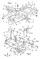
- the X and Y directions jointly define a principal X, Y plane (intersecting linearly with that of the sheet on the figure 1 ) within which the lift polygon and a landing plan are inscribed.
- reference numeral 1 designates, in general, a modern rotary wing aircraft, of the hybrid helicopter type.
- this hybrid helicopter 1 comprises a fuselage 2, in front of which is provided the cockpit 3.
- a rotary wing in the form here of main rotor 4 is intended to drive in rotation blades 5, four in number on the example of the figure 1 .
- Reference numeral 9 denotes in broken lines on the figure 1 , a main gearbox (BTP) of power of the motorization of the rotor 4 and propulsion arrangements 10.
- BTP main gearbox
- the hybrid helicopter 1 comprises several motorization groups 8 each arranged transversely to each other, within the fuselage 2, on either side with respect to a longitudinal plane of symmetry in elevation. of the device 1.
- these two groups of engines 8 take the form of turboshaft engines, respectively to the right and to the left, and are not directly visible due to the presence of fairings.
- Each engine group 8 is connected to a propulsion arrangement 10, by the main gearbox 9 (BTP).
- these two groups of engines 8 drive in rotation the rotary wing formed by the rotor 4, in particular through the main gearbox 9.
- each of these groups of motorization 8 carries and ensures the rotational drive of the propulsion arrangements 10.
- Each of these propulsion arrangements 10 is essentially in the form of a helix, the blades of which have an adjustable pitch in order to modify the thrust.
- each of the propulsion arrangements 10, left and right, is mounted on a substantially longitudinal axis of rotation (direction X on the Figures 1 and 2 ). More specifically, each of the propulsion arrangements 10 is mounted on an opposite side transversely of the fuselage 2 to the axis of the other propeller and propulsion arrangement 10. Note that each propulsion arrangement 10 has a substantially fixed axis.
- the hybrid helicopter 1 is provided with a fixed wing 11 composed of two half-wings 12 and 13, one on the left and the other on the right. These two half-wings 12 and 13 are arranged, according to the example shown in FIG. figure 1 , at a portion of the fuselage 2 substantially summit in elevation (Z direction).
- the fixed wing 11 is so-called high.
- the propulsion arrangements 10 are arranged respectively to the left and to the right of the fuselage 2, on the half-wing 12 and the half-wing 13.
- Each propulsion arrangement 10 is mechanically connected to the main transmission box 9 (BTP), but also from a control point of view, by unrepresented structures, within these half-wings 12 and 13.
- the hybrid helicopter 1 comprises a set of stabilizing and operating surfaces 14 disposed near a rear portion 15 of the fuselage 2.
- This assembly 14 is here generally U-shaped overturned, and present for maneuvers change of depth, a horizontal empennage 16 with two control surfaces. depth 17 movable with respect to a front and fixed part of the horizontal empennage 16.
- the assembly 14 For flight attitude change maneuvers of the hybrid helicopter 1, the assembly 14 has two substantially vertical stabilizers 18, on each side of a horizontal stabilizer 16, that is to say at its outer transverse ends . On each empennage 18, a rudder 19 is movably mounted.
- the pilot has in particular a manual thrust control member, designated 20.
- This member 20 conventionally makes it possible to modify the average pitch of the propeller blades of the arrangements. propulsion 10.
- this manual control member 20 is arranged in the cockpit 3.
- a cyclic pitch lever which serves as a manual flight control device 21, is arranged in the cockpit 3 of the hybrid helicopter 1.
- This manual flight control device 21 acts either on the attitude changes in pitch, or on the attitude changes in roll, of the hybrid helicopter 1.
- the thrust is produced solely by the inclination of the rotary wing, and is controlled via the cyclic pitch lever and the associated cyclic plates while automatic regulation is provided on the turbine-engine helicopters between pitch and power to prevent the rotor from slowing down when increasing the overall pitch of the rotor blades so the lift, at the same time the drag and hence the necessary power.
- Thrust Control Lever For this manual flight control device 20, sometimes referred to as "Thrust Control Lever” or TCL, in English, by analogy with the manual thrust controls aircraft for example.
- control member 20 acts identically on the pitch of the blades of the two propellers of the arrangements 10, in order to obtain a collective variation of these steps.
- the pilot will require a 5 ° increase in the pitch of all the propellers of the arrangements 10 to increase the resulting longitudinal thrust, generated in particular by these propellers.
- a first extreme position 22 forward is considered 100%.
- a second extreme position 23 towards the rear, is considered at 0%.
- These first and second extreme positions 22 and 23 respectively correspond to a maximum value and to a minimum thrust value, which is in principle zero.
- a kinematic flight attitude change chain 25 acts on the cyclic plates 6 for adjusting the cyclic pitch of the blades of the rotary wing formed by the main rotor 4.
- the pilot can act on the attitude in pitch and roll of the hybrid helicopter 1.
- the transverse displacements on the device 21, left and / or right, cause roll attitude changes of the hybrid helicopter 1, to the left and the right respectively.
- Each of these flight attitude change drift chains 24 and 25 has a power assist 26 and 27 respectively.
- These audiences in power 26 and 27 are here in the form of one or more hydraulic cylinders 28 and 29, and are constantly activated.
- kinematic flight attitude change chains 24 and 25 include other cylinders, including those called “TRIM” for the autopilot control. These TRIM jacks are generally of the electric and parallel type. Still other cylinders, for example electric and in series, are arranged in such kinematic chains of flight attitude change 24 and 25.
- the cyclic plates 6 of the rotary wing 4 cooperate with several jacks 29, including two transverse cylinders 29 for rolling adjustments, and a central cylinder 29 for pitch adjustments.
- the kinematic chain of flight attitude change 24 conventionally comprises in the aeronautical field, since its manual control member 20, a linkage 30 with various return rods and joints which lead first to the assistance 26 and then to a conventional pitch adjustment mechanism of each propeller propulsion arrangement.
- the kinematic chain of flight attitude change 25 conventionally comprises in the field of rotorcraft, since its so-called cyclic manual flight control device 21 for pitch attitude changes, a linkage 31 with various return rods or horns and joints 35 which lead first to a pitch damping device 32, then to the assistance 27 and finally to conventional cyclic plates 6 for adjusting the cyclic pitch of the blades 5 of the rotary wing 4.
- the hybrid helicopter 1 is equipped with an autopilot 33 which is symbolized in dotted lines on the Figures 1 and 2 .
- This autopilot 33 is here connected to an electronic logic circuit 34, so as to be able to act on the assistance 27 in the adjustment power of the cyclic pitch of the blades 5 of the main rotor 4. This action of the autopilot 33 is notably based on the instantaneous airspeed of the hybrid helicopter 1.
- the connection to the autopilot (PA) is not planned.
- the autopilot 33 acts on the power assistance of the cyclic pitch of the wing 4, it is representative parameters of the load factor that determine the law of predetermined damping force.
- these parameters are the propulsive pitch (according to the member 20), the speed of movement of the device 21 which are taken into account for this determination of the law of predetermined damping force.
- this structure is a rotary damper, consequently also referenced 32, which is arranged in the flight kinematic pitch attitude change system 25.
- a damping motor similar to the motor 32 is arranged directly at an axis of articulation of a return of the kinematic chain of flight attitude change concerned.
- this torque is designated by the arrow C.
- This torque C generates, in a direction of rotation or in the opposite direction, a damping force which is designated F on said figure 2 .
- this damping force F is here linear and acts on the kinematic chain of pitch attitude change 25.
- This damping force F also in accordance with the law of predetermined damping force A, is applied in the illustrated example to a connecting rod 125 of the kinematic chain of flight attitude change 25 in pitch.
- haptic restitution effort 61 also called “damping force”, illustrated on the figure 2 or on the figure 5 (in this figure, in Nm / rd / s).
- This haptic restitution effort 61 which results from the law of predetermined damping force A, acts on the manual flight control device 21 dedicated to pitching, namely the cyclic pitch stick. This action of the haptic restitution effort 61 is obviously proportional to the damping force F and oriented in a corresponding direction.
- the haptic restitution effort 61 is also dependent in terms of direction, velocity and acceleration, of the architecture of said flight attitude change kinetic chain to which it applies.
- variable hardening One of the goals of this variable hardening is to avoid that the driver orders a command too brutal, at the risk of confronting conditions that may lead to autocamping, for example.
- said law of predetermined damping force A maneuvers of this manual flight control device 21 is here predetermined according to an instantaneous load factor of the hybrid helicopter 1, so that this load factor snapshot is maintained between its minimum and maximum limit values.
- variable stiffness of the actuation of said manual flight control device 21 has in particular an initial component generated by the assistance 27 for a prior state, a variable component specific to the haptic restitution defined according to said law of effort of predetermined damping A according to the invention, and naturally a substantially constant component specific to the friction of said kinematic flight control system 25.
- Such a predetermined damping force law A applies according to one embodiment of the invention to the pitch attitude change and / or roll pitch chain.
- TTL parameter namely the instantaneous position of the manual thrust control member as specified later.
- the law of predetermined damping force A is defined proportionally to a position of said manual control member 20 of the thrust, between its two extreme positions 23 and 22 which respectively correspond to a minimum value of zero principle of thrust in hovering and a maximum value of thrust permissible by the propulsion arrangements 10.
- the kinematic change chain attitude in flight flight 25 to which said law of predetermined damping force A is to be applied is integrated into the hybrid helicopter 1 in parallel with the kinematic attitude change in flight 24 which acts on the thrust .
- this haptic system also applies according to the invention to a kinematic chain 250 acting on the roll attitude of the hybrid helicopter 1.
- said kinematic chain of flight attitude change 24 in thrust comprises at least two pivoting pivoting joints 35.
- the haptic feedback system has a thrust control position sensor 36.
- This sensor 36 is operatively connected to said controller 20 so as to produce an electrical signal indicative of the position of this member 20 between its minimum and maximum thrust values.
- this sensor 36 is of the variable rotation differential differentiator (RVDT) type, for example of the potentiometer type.
- the pitch flight attitude change train 25 comprises, among the pivoting pivot joints, a damper 32 of the maneuvers of said manual flight control device 21.
- the damper 32 includes an "inverted engine", that is, an alternator 56.
- the alternator 56 which forms the damper 32 has a plurality of alternator stator windings designated 37, 57 and 58.
- the damper 32 of the thrust modification maneuvers by the propulsion arrangements 10 is therefore an alternator 56.
- This alternator 56 is connected by its terminals, so that it delivers in the logic circuit 34 which is resistant, so as to produce a contro-motor force proportional to the speed of rotation of said hinge 35 receiving the damper 32.
- a measuring member of this speed is not essential.
- This proportional contromotomotor force participates in the braking of the manual flight control device 21, and constitutes the variable component of the haptic restitution torque.
- a sensor 38 dedicated to this speed measurement.
- Such a sensor 38 is substituted for or added to another speed measuring device. As illustrated on the figure 2 the sensor 38 is attached to the articulation 35 to determine the rotational speed.
- the manual flight control device 21 is functionally coupled to a such a sensor 38 operating speed.
- This sensor 38 produces a maneuver speed signal proportional to the instantaneous speed at which this manual flight control device 21 is actuated.
- This speed signal coming from the sensor 38 -or the signal coming from the alternator 56- is integrated as a parameter (referred to above as "outside") to the law of predetermined damping force A, by an electrical connection. which connects to the logic circuit 34 said sensor 38.
- the haptic feedback system comprises its sensor 36 capable of providing the instantaneous position of said manual flight control member 20.
- the haptic feedback system comprises the motor 37 which is also called the “damping motor” or " rotary motor "by the way.
- this motor 37 has the function of damping the maneuvers of the manual flight control device 21.
- the haptic feedback system comprises the sensor 38 which measures the speed of said manual flight control device 21.
- All these components of the haptic rendering system are functionally connected to the electronic logic circuit 34, to directly define the damping as a function of the predetermined damping force law A.
- This haptic feedback system logically leads to the manual flight control device 21, and brakes in the direction proper to the flight control maneuver applied by the pilot, but in the opposite direction to the action of the latter.
- This braking initially takes the form of a damping force F, according to said predetermined law L of variation of the damping coefficient, applied for example to the connecting rod 125 of the flight attitude change kinematic chain 25.
- the damping force F is substantially equal to the torque introduced by the damping motor 37, divided by the dimension of a lever referred to as "d" on the figure 2 .
- This lever arm "d” is measured between the axis of rotation of said damping motor 37 and the connecting rod 125.
- sensors 36 and / or 38 are of the type with differential variable rotation transformation (RVDT). In other embodiments, these are sensors 36/38 either analog or digital, such as Hall effect sensors, optical sensors, or the like.
- RVDT differential variable rotation transformation
- the system includes a calculator (schematized at 62 on the figure 1 ) to which are connected at least one position sensor 36 of said manual control member 20, a damper 32 of the maneuvers and optionally a speed sensor 38.
- this manual flight control device 21 and the autopilot 33 act on the cyclic pitch of the blades 5 of the main rotor 4. This is only indirectly that the maneuvers of the manual control member 20 (TCL) brake said manual flight control device 21.
- This adjustment of the thrust control is meant for the autopilot 33, which adapts in response to at least one flight parameter such as engine speed of the engine arrangements 10.
- the logic circuit 34 is independent of the autopilot 33.
- an instantaneous value of the position of the manual control member 20 thrust is supplied to a capture area 41 of said instantaneous position value, between the extreme front 22 and rear 23 positions.
- a significant signal of this instantaneous position is for example produced by the sensor 36 of the chain 24. It has been seen that this sensor 36 may be of different types, including that of a potentiometer.
- This capture area 41 comprises a variable resistor 42, connected in series between a source 43 of direct current and one of the grounds of the circuit 34 which are all designated at 44.
- a signal shaping zone 45 At the output of the variable resistor 42 is connected a signal shaping zone 45. This zone 45 makes it possible to translate the position signal coming from the sensor 36 into a variable load reference.
- the zone 45 comprises a series succession of two amplifier amplifier inverter amplifiers 46 and resistors 47.
- Each amplifier has its own source 43, its own grounding 44 and a exit. We see a resistance 461 between the two amplifiers 46 on the figure 3 .
- the output of the zone 45 and thus of a second operational amplifier 46 opens in series on a variable load processing zone 48, provided with a field effect transistor 49, whose function is to control the load by means of intermediary of an electronic control.
- this transistor 49 is of the MOSFET type.
- a rectification treatment zone 50 is connected in series.
- the rectification treatment zone 50 comprises, in parallel, three ramps of two diodes 51 in series, each of which opens onto a distinct line junction 52. Thanks to the transformation carried out by the rectification treatment zone 50, a current is obtained. even to be addressed via its own connection line 52.
- connection lines 50 form a zone 53 for processing the minimum load.
- a first bridge 54 of this zone 53 of minimum load connects a line 52 to its opposite line 52, and comprises in series a single resistor 47.
- a second bridge 55 of this zone 53 connects the lines 52 and has a resistor 47 in series between each line 52. It is understood that this zone 53 of treatment ensures a minimum load coefficient of thrust.
- the damping coefficient is order of 3.2 Nm / rd / s (for Newton-meter / radian / second).
- the damping coefficient is of the order of 14.3 Nm / rd / s. In the latter case, the average collective pitch of the propeller blades is maximum.
- the treatment zone 53 ensures a minimum damping, for which the damping coefficient produced by the damper 32 (motor 37) is of the order of 3.1 to 3.2 Nm / rd / s. Then the position of the manual control member 20 is 0%, which corresponds to the rearmost position 23.
- a connection line 52 is dedicated to a so-called “motor” component of this zone 56, that is to say to dampers acting on a kinematic chain of change. attitude in specific flight.
- dampers 32 maneuvers manual thrust control member 20, these dampers of the motor zone 56 produce a braking counterelectromotive force proportional to the desired haptic restitution.
- the damper 32 also comprises a multiplier stage connected to the flight attitude change train 25 and an alternator rotor 56.
- the manual flight control device 21 with maneuver damping acts on the pitching behavior of the hybrid helicopter 1.
- the invention obviously being applicable to various chains kinematics of attitude change in flight and various types of aircraft.
- another manual flight control device 21 connected to the logic circuit 34 is subject to a maneuver damping by haptic restitution according to the invention.
- This haptic restitution is obtained via the actuation of another "engine” 57, and acts on the roll or yaw behavior of the hybrid helicopter 1.
- one of the manual flight control devices 21 haptic restitution according to the invention acts on the roll of the hybrid helicopter 1.
- This haptic restitution would be in such an example, operated by an "inverted motor" of the figure 3 .
- Such a predetermined damping force law A is pre-established so that said instantaneous load factor is maintained between its minimum limit and maximum limit values, in proportion to a position of the manual control member 20 (TCL) of the thrust. between the values and extreme positions 22 maximum and 23 minimum principle in principle zero.
- This haptic restitution effort F is substantially equal to the torque C exerted by the shock absorber 32, divided by the lever arm "D" between the axis of rotation of said damper 32 and the corresponding articulation of said connecting rod 125.
- Damping coefficients are variable with a damper 32 in the form of the motor 37. These coefficients correspond to the predetermined law L of variation of the damping coefficient.
- An example of such a law of variation of the damping coefficient L is represented on the figure 4 .
- the damping laws L and the predetermined damping force law A are recorded in the computer 62 ( figure 1 ).
- this predetermined law L of variation of the damping coefficient which makes it possible to weight the maneuvers of the manual flight control device 21 relative to the position of a manual thrust control member 20 is therefore substantially linear, between 0% and 100% of the average collective pitch stroke of propeller propeller propellers 10.
- Such a race is sometimes referred to as the "collective thrust command” or "TCL parameter" as previously discussed.
- the damping coefficient produced by the shock absorber 32 is of the order of 3.2 Nm / rd / s.
- the damping obtained by the actuation of the motor 37 corresponds, when said manual control member 20 orders a thrust with a maximum value of 100% (extreme position before 22), to a haptic restitution braking itself maximum.
- said damping coefficient is of the order of 14.3 Nm / rd / s, if the haptic effect of the damper 32 in accordance with the predetermined law L of variation of the damping coefficient is maximum.
- said cyclic pitch adjustments of the rotor blades 4 of the hybrid helicopter are caused by means of said power assistance 27, this assistance 27 being at least partially defined by said autopilot 33, but independently of said law of predetermined damping force A, that is to say indirectly after treatment by the circuit 34, without direct link with the maneuvers operated on the manual control member 20 thrust.
- said cyclic pitch adjustments of the blades 5 of the rotary wing 4 of the hybrid helicopter 1 are caused by means of said power assistance, this assistance being at least partially defined by said pilot automatic 33, independently of said predetermined law of damping force A which depends on the maneuvers of the manual thrust control member 20.
- the maneuvers on said manual thrust control member 20 act directly and / or through a power assist on the thrust adjustment, this adjustment being signified to the autopilot, the latter then adapting response to at least one flight parameter such as engine speed of the engine arrangements 10, adaptation which in turn induces a definition of a new assist instruction to the adjustment of the cyclic pitch of the blades 5 of the rotary wing 4, indirectly and therefore independent
- said minimum limit values and maximum load factor limit are calibrated to prevent the hybrid helicopter 1 from reaching threshold states of autocabrication.
- the values of the damping force 61 according to the invention are shown on the ordinate, and the abscissa the rotational speed of operation of a manual flight control device 21 subject to the law of predetermined damping force A.
- the haptic restitution efforts 61 defined for example as a function of the torque C represented in FIG. figure 2 and restored in this manual flight control device 21 from a force F, are constantly increasing or decreasing, even when the device 21 is actuated with a reversal of direction.
- This directional reversal of the manipulations of said manual control device 21 is represented on the abscissa by negative left-hand and right-positive angular values of the instantaneous maneuvering position of this device 21 between two maximum and minimum extreme positions.
- the invention is related to the possibilities of increasing the speed of travel in advance, that is to say, longitudinal direction X, made possible with rotary wing aircraft hybrid type for example such as explained in the documents FR 2 916 418 , FR 2 916 419 and FR 2 916 420 .
- the aerodynamic loads are no longer returned to the controls, and can no longer be perceived by the pilot. It is no longer warned of a situation of fatigue of materials or danger. In this way, the pilot may not be able to react.
- Hybrid-type rotary wing aircraft whose aerodynamic surface controls are motorized and which are capable of attaining air speeds and / or significant load factors.
- a common way in practice to try to limit the risks of autocorrugation of a helicopter is to restore the effect of aerodynamic loads by artificial response constraints damped in the controls, more or less proportional.
- the helicopters are equipped with constant gain feedback dampers, particularly because of their relatively low forward speed compared to that of a hybrid aircraft with rotary wing.
- dampers are coupled to the roll, pitch and yaw controls.
- This hybrid helicopter 1 drone has a cockpit 3, which is here outboard, that is to say, at a distance from the fuselage 2.
- this remote station 3 is installed so as to be actuated by a radio-control operator (not shown), a weighting flight control device 21, here which acts on the pitch orientation and / or roll of the hybrid helicopter drone 1.
- This station 3 further has a thrust control member 20, which cooperates with the device 21 as explained above, to produce the values of variable restitution efforts.
- a haptic effect in return of effort restitution adapted to hybrid helicopters 1 is obtained, and applied including pitching commands, and lower roll level.
- the choice of a haptic feedback to the controls of the hybrid helicopter 1 according to the invention is perfectly adapted to the movements of the manual devices (comparable to the device 21) flight control, to ensure a particularly precise and comfortable steering.
- Another advantage obtained for the hybrid helicopter 1 according to the invention is increased durability of the aircraft, due to less damage to its constituents concerned, in particular its aerodynamic surfaces and their control and control mechanisms.
- embodiments of the invention not illustrated relate to a haptic feedback applied to the yaw control flight control, which is therefore to be considered as a manual flight control device, as the handle designated 21.
- the invention makes it possible to apply a haptic restitution to a flight control device 21 in the form of a lever for maneuvering the collective pitch of the blades 5 of the rotary wing 4 of the hybrid helicopter 1.
Abstract
Description
La présente invention vise un amortissement à coefficient variable d'une restitution haptique dans une commande de vol manuelle agissant sur une chaîne cinématique de changement d'attitude de vol d'un aéronef.The present invention aims a variable coefficient damping of a haptic rendering in a manual flight control acting on a kinematic chain of flight attitude change of an aircraft.
Dans les exemples, l'invention est décrite dans le cas d'une commande de pas cyclique des pales d'une voilure tournante d'un hélicoptère de type dit hybride.In the examples, the invention is described in the case of a cyclic pitch control of the blades of a rotary wing of a hybrid type helicopter.
Un hélicoptère hybride est un concept avancé d'aéronef à décollage et à atterrissage verticaux, désigné « VTOL Aircraft » pour « Vertical Take-Off and Landing Aircraft » en langue anglaise. Des exemples de réalisation d'un tel hélicoptère hybride sont par exemple décrits dans les documents
Cet hélicoptère hybride allie à un coût raisonnable l'efficacité du vol vertical de l'hélicoptère conventionnel aux performances à grande vitesse sur trajectoire longitudinale, par exemple jusqu'à une vitesse d'avancement en croisière de l'ordre de 400 km/h, voire d'avantage, mais également à une grande distance franchissable.This hybrid helicopter combines at a reasonable cost the efficiency of the vertical flight of the conventional helicopter with high speed performance on longitudinal trajectory, for example up to a cruising speed of the order of 400 km / h, even more, but also at a great distance.
D'un point de vue structurel, un hélicoptère hybride est remarquable notamment par trois aspects.From a structural point of view, a hybrid helicopter is remarkable in particular by three aspects.
Ainsi, en vol d'avancement sur trajectoire, une partie de la portance d'un hélicoptère hybride est assurée par une voilure tournante sous forme d'au moins un rotor principal, dont l'axe de rotation ou mât n'est pas basculant, à l'inverse de ceux d'un appareil convertible tel qu'un appareil Bell-Boeing V22 Osprey.Thus, in flight trajectory advancement, part of the lift of a hybrid helicopter is provided by a rotary wing in the form of at least one main rotor, whose axis of rotation or mast is not tilting, unlike those of a convertible device such as a Bell-Boeing V22 Osprey.
Ceci distingue l'hélicoptère hybride non seulement de tels appareils convertibles, mais également et par définition des aéronefs à voilure fixe. Un hélicoptère hybride est donc à considérer comme un aéronef à voilure tournante de nouvelle génération.This distinguishes the hybrid helicopter not only from such convertible aircraft, but also and by definition from fixed wing aircraft. A hybrid helicopter is therefore to be considered as a new-generation rotary wing aircraft.
Par souci de simplicité, on désigne ci-après par voilure tournante le ou les rotors de sustentation d'un tel aéronef, et par disque rotor la surface géométrique définie par un tel rotor.For the sake of simplicity, hereinafter referred to as rotary wing the lift rotor or levers of such an aircraft, and rotor disk by the geometric surface defined by such a rotor.
Cependant, un hélicoptère hybride comporte en plus de sa voilure tournante, une voilure dite fixe par exemple sous la forme de deux demi-ailes étendues transversalement de part et d'autre d'un fuselage.However, a hybrid helicopter has in addition to its rotary wing, a so-called fixed wing for example in the form of two half-wings extended transversely on either side of a fuselage.
Cette voilure fixe assure une partie de la portance en vol d'avancement, d'autant plus importante que la vitesse longitudinale de l'hélicoptère hybride est élevée.This fixed wing provides part of the lift in forward flight, all the more important that the longitudinal speed of the hybrid helicopter is high.
De part et d'autre et à distance transversalement du fuselage, il est prévu pour ce faire, au moins un agencement de propulsion typiquement sous forme d'au moins une hélice de poussée. Au moins un groupe de motorisation tel qu'un turbomoteur entraîne en rotation simultanément la voilure tournante, typiquement un rotor principal, ainsi que les agencements de propulsion.On both sides and at a transverse distance from the fuselage, at least one propulsion arrangement is provided for this purpose, typically in the form of at least one thrust propeller. At least one engine group such as a turbine engine simultaneously rotates the rotary wing, typically a main rotor, and the propulsion arrangements.
En outre, les agencements de propulsion produisent un couple de stabilisation longitudinale, du fait de leur fonctionnement qui est à poussée différentielle. Cet hélicoptère hybride peut ainsi être dénué de rotor anti-couple.In addition, the propulsion arrangements produce a longitudinal stabilizing torque, because of their operation which is differential thrust. This hybrid helicopter can thus be devoid of anti-torque rotor.
Toutefois, un hélicoptère hybride est pourvu de surfaces aérodynamiques de stabilisation et de manoeuvre de type empennages et gouvernes.However, a hybrid helicopter is provided with aerodynamic stabilization surfaces and maneuvering type empennages and control surfaces.
Un autre aspect distinctif de l'hélicoptère hybride est qu'une chaîne cinématique de changement d'attitude en vol, proportionnelle à rapports constants en termes de vitesses de rotation relie la voilure tournante, les groupes de motorisation et donc des agencements de propulsion.Another distinctive aspect of the hybrid helicopter is that a kinematic chain of change of attitude in flight, proportional to constant ratios in terms of rotation speeds connects the rotary wing, the groups of motorization and therefore propulsion arrangements.
Ceci différencie l'hélicoptère hybride d'un autogire tel que celui de La Cierva, d'un hélicoptère combiné tel que le SO10 Farfadet, ou encore d'un girodyne tel que le Jet Rotodyne de Fairey, le rotor principal de tous ces appareils étant en autorotation sous l'effet de la vitesse d'avancement pour les vols sur trajectoire.This differentiates the hybrid helicopter from a gyrocopter such as that of La Cierva, from a combined helicopter such as the SO10 Farfadet, or from a girodyne such as Jet Rotodyne from Fairey, the main rotor of all these aircraft being in autorotation under the effect of the speed of advance for flight on trajectory.
En modifiant collectivement et d'une même quantité le pas des pales des hélices des agencements de propulsion, il est en outre possible de contrôler la poussée d'avancement de cet l'hélicoptère hybride, qui est générée par ces agencements.By modifying collectively and in the same quantity the pitch of the propeller blades of the propulsion arrangements, it is also possible to control the forward thrust of this hybrid helicopter, which is generated by these arrangements.
Cependant, du fait des vitesses d'avancement élevées que peut atteindre un hélicoptère hybride, celui-ci est soumis à un risque accru d'autocabrage ou en langue anglaise « pitch-up », comportement qui est expliqué par la suite.However, because of the high speeds of advance that can reach a hybrid helicopter, it is subject to an increased risk of autocamping or English language "pitch-up" behavior that is explained later.
Le domaine technique de l'invention est donc le domaine technique restreint des commandes de vol d'un hélicoptère hybride.The technical field of the invention is therefore the restricted technical field of flight controls of a hybrid helicopter.
Dans ce domaine, le document
Le document
Bien qu'intéressantes, ces solutions semblent peu adaptées au contexte très particulier d'un hélicoptère hybride.Although interesting, these solutions seem not very adapted to the very particular context of a hybrid helicopter.
On peut également citer le document
Plus la vitesse de l'avion augmente et plus est accrue la réaction, depuis une position donnée du manche et des surfaces aérodynamiques de l'avion associées à ce manche.As the speed of the aircraft increases, so does the reaction from a given position of the stick and the aerodynamic surfaces of the aircraft associated with that stick.
Ces surfaces aérodynamiques sont des volets articulés sur les ailes de la voilure fixe de l'avion. Divers facteurs influant sur cette réaction sont pris en considération dont le taux de mouvement du manche, la capacité de taux de manoeuvre (en langue anglaise « Slew Rate Capacity ») des surfaces aérodynamiques ainsi que la capacité de charge de ces surfaces.These aerodynamic surfaces are flaps articulated on the wings of the fixed wing of the aircraft. Various factors influencing this reaction are taken into account including the rate of movement of the handle, the capacity of maneuvering rate (in English "Slew Rate Capacity") of the aerodynamic surfaces and the carrying capacity of these surfaces.
Une unité de commande de vol est couplée à une motorisation par un circuit de commande, pour fournir au moins un signal de déclenchement de force de réaction, afin de définir la capacité de taux de manoeuvre des surfaces aérodynamiques de l'avion.A flight control unit is coupled to an actuator by a control circuit to provide at least one reaction force trigger signal to define the maneuverability capability of the aerodynamic surfaces of the aircraft.
Le document
Le document
Le document
Des actionneurs concentriques à valves ainsi que divers paramètres de limitation de charge sont décrits. Ce document porte sur des lois d'effort ou d'amortissement, à gain constant, c'est-à-dire fixe.Concentric valve actuators and various load limiting parameters are described. This document relates to laws of effort or damping, constant gain, that is to say fixed.
Le document
Divers types de capteurs sont mentionnés, soit analogiques soit numériques, tels que les capteurs à effet Hall, des capteurs optiques, des capteurs de transformation différentielle variable de rotation (Rotary Variable Differential Transformer ou RVDT en langue anglaise).Various types of sensors are mentioned, either analog or digital, such as Hall effect sensors, optical sensors, variable variable differential transformers (RVDTs).
Le document
Ce document
Ces documents étant mentionnés, il est maintenant plus aisé d'exposer les divers problèmes techniques à la base de l'invention.These documents being mentioned, it is now easier to expose the various technical problems at the base of the invention.
De ce qui précède, on comprend que du fait notamment des vitesses d'avancement d'un hélicoptère hybride, supérieures à celles d'un aéronef à voilure tournante usuel, ainsi que de la relative complexité des équilibrages fonctionnels à prévoir pour l'optimisation en vol d'un tel appareil, il a été préféré de doter certaines commandes des hélicoptères hybrides de mécanismes d'assistance en puissance.From the foregoing, it is understood that, in particular because of the speeds of advance of a hybrid helicopter, higher than those of a conventional rotary wing aircraft, as well as the relative complexity of functional balancing to be provided for In flight optimization of such a device, it has been preferred to equip certain commands of hybrid helicopters with power assistance mechanisms.
Ces mécanismes d'assistance ajustent l'état de surfaces aérodynamiques telles que rotors, hélices, gouvernes ou empennages en fonction de signaux de commande. Selon les cas, ces mécanismes d'assistance ont des sources de puissance en général de type hydraulique comme pour les servocommandes, tandis que pour la commande du pilote automatique ce sont des vérins électriques qui interviennent le plus souvent.These assistance mechanisms adjust the state of aerodynamic surfaces such as rotors, propellers, control surfaces or empennages as a function of control signals. Depending on the case, these assistance mechanisms have power sources generally of the hydraulic type as for the servocontrols, while for the control of the autopilot these are electric cylinders that intervene most often.
Les signaux de commande sont générés soit par des actions de l'être humain qui pilote l'hélicoptère hybride, soit par un pilote automatique, soit sont formés à partir d'une combinaison de signaux d'origine humaine et automatique.The control signals are generated either by actions of the human being piloting the hybrid helicopter, or by an autopilot, or are formed from a combination of human and automatic signals.
Un inconvénient connu des commandes assistées en puissance de type au moins partiellement manuelles, est qu'elles ne restituent pas au niveau de l'organe de commande manoeuvré par le pilote, les efforts appliqués à un instant donné sur les surfaces aérodynamiques. Selon les cas, les organes de commande manuelle de vol sont des leviers, manches, boutons, etc.A known disadvantage of power assisted controls at least partially manual type is that they do not restore the level of the control member operated by the driver, the forces applied at a given moment on the aerodynamic surfaces. Depending on the case, the manual flight control members are levers, handles, buttons, etc.
Dans le cas d'un hélicoptère hybride de tels organes de commandes sont en général disposés dans le poste de pilotage de l'appareil.In the case of a hybrid helicopter, such control members are generally arranged in the cockpit of the aircraft.
Dans ces conditions, l'ajustement du pas cyclique des pales de la voilure tournante est usuellement conçu pour que le manche cyclique reste ancré dans une position d'équilibre compensé dite « neutre», sans intervention du pilote.Under these conditions, the adjustment of the cyclic pitch of the blades of the rotary wing is usually designed so that the cyclic stick remains anchored in a balanced equilibrium position called "neutral", without intervention of the pilot.
Quand ce manche cyclique est dans cette position neutre, l'ajustement cyclique du rotor principal par un système de commande cyclique dit "Cyclic Control System" (CCS) définit une nouvelle position d'équilibre de commande de l'appareil.When this cyclic stick is in this neutral position, the cyclic adjustment of the main rotor by a cyclic control system called "Cyclic Control System" (CCS) defines a new control equilibrium position of the apparatus.
Les caractéristiques mécaniques principales d'un système CCS relèvent des efforts ou forces perçues par le pilote à travers le manche cyclique pendant les manoeuvres de ce dernier.The main mechanical characteristics of a CCS system relate to the forces or forces perceived by the pilot through the cyclic stick during the maneuvers of the latter.
Typiquement, les forces caractéristiques qui sont relatives à un ajustement de type CCS dans un hélicoptère standard à commandes de vol mécaniques, sont réductibles:
- aux forces d'ancrage, qui sont appliquées pour recentrer le manche à sa position neutre de "TRIM", ces forces étant constantes quelle que soit l'amplitude ou la rapidité de déplacement du manche cyclique ;
- aux forces de recentrage auxiliaires du manche cyclique vers sa position neutre, celles-ci étant proportionnelles au déplacement du manche par rapport à la position neutre ;
- à la force de friction constante opposée aux déplacements du manche ;
- à la force proportionnelle à la rapidité de déplacement du manche, afin de pallier aux manoeuvres brutales ; et
- à la force d'arrêt apte à stopper le déplacement à une position établie en fonction de limites des conditions de vol et matérialisée par une sorte de butée normalement escamotée.
- the anchoring forces, which are applied to refocus the stick to its neutral position of "TRIM", these forces being constant regardless of the amplitude or the speed of movement of the cyclic stick;
- the auxiliary centering forces of the cyclic stick to its neutral position, these being proportional to the displacement of the handle relative to the neutral position;
- constant frictional force opposing the movements of the handle;
- the force proportional to the speed of movement of the handle, in order to overcome the brutal maneuvers; and
- the stopping force capable of stopping the displacement at an established position according to the limits of the flight conditions and materialized by a sort of stop normally retracted.
Un système de pilotage automatique permet d'agir sur la commande dite ici manche cyclique, en réglant automatiquement la position neutre. Il est courant d'inclure dans le poste de pilotage, qu'il soit à bord ou hors bord, un organe de relâchement de position neutre (« TRIM release » en langue anglaise), typiquement disposé sur la poignée du manche cyclique. Ce bouton permet au pilote de déplacer le manche jusqu'à n'importe quelle position et de demander au pilote automatique de maintenir cette nouvelle position une fois ledit bouton relâché.An autopilot system makes it possible to act on the so-called cyclic stick command, by automatically adjusting the neutral position. It is common practice to include in the cockpit, whether on board or outboard, a release neutral position ("TRIM release" in English), typically arranged on the handle of the cyclic handle. This button allows the pilot to move the stick to any position and to ask the autopilot to maintain this new position once the button is released.
Souvent également, un commutateur à cinq états dont un état central stable permet de modifier la position neutre, ou attitude de l'hélicoptère, dans les quatre directions cardinales. Classiquement aussi, il doit être possible que le pilote dirige l'hélicoptère sans débrayer les efforts évoqués.Also often, a five-state switch with a stable central state allows to change the neutral position, or attitude of the helicopter, in the four cardinal directions. Classically also, it must be possible for the pilot to steer the helicopter without disengaging the efforts mentioned.
On note que classiquement, le manche cyclique d'un hélicoptère permet de commander un tel aéronef en tangage et en roulis, théoriquement de manière indépendante, c'est-à-dire sans influence parasite d'une manoeuvre de tangage sur l'attitude de l'aéronef en roulis, et inversement.Note that conventionally, the cyclic stick of a helicopter makes it possible to control such an aircraft in pitch and roll, theoretically independently, that is to say without parasitic influence of a pitching maneuver on the attitude of the aircraft in roll, and vice versa.
En d'autres termes, une manoeuvre de tangage pur par le pilote est exclusivement transmise vers la voilure tournante par une chaîne cinématique de changement d'attitude en vol en tangage, sans influence au sein de la chaîne cinématique de changement d'attitude en vol en roulis qui est également manoeuvrée par le manche cyclique.In other words, a pure pitching maneuver by the pilot is transmitted exclusively to the rotary wing by a kinematic chain of attitude change in pitch flight, without influence within the kinematic chain of attitude change in flight. in roll which is also manipulated by the cyclic stick.
Similairement, une manoeuvre en roulis pur sur le manche cyclique n'agît pas sur la chaîne cinématique de changement d'attitude en vol en tangage.Similarly, a maneuver in pure roll on the cyclic stick does not act on the kinematic chain of attitude change in pitch flight.
Par ailleurs, il est rappelé qu'une manoeuvre quelconque du manche cyclique permet un changement d'attitude simultanément en tangage et en roulis d'un aéronef à voilure tournante.Furthermore, it is recalled that any maneuver of the cyclic stick allows a change of attitude simultaneously in pitch and roll of a rotary wing aircraft.
Cependant, il est courant qu'en aval des deux chaînes cinématiques autonomes en tangage et roulis, directement issues du manche cyclique, des paramètres imposés pour le vol de l'aéronef provoquent des changements d'attitude en tangage, roulis, voire lacet, lors d'une manoeuvre du pilote sur ledit manche de commande en tangage ou roulis.However, it is common that downstream of the two autonomous kinematic chains in pitch and roll, directly cyclic stick, parameters imposed for the flight of the aircraft cause attitude changes in pitch, roll, or yaw, during a maneuver of the pilot on said control stick in pitch or roll.
Ceci étant exposé, on comprend que les commandes manuelles assistées en puissance, telles que celles qui agissent sur les positions en tangage, lacet et roulis d'un aéronef, privent son pilote de naturellement ressentir les forces de réaction renvoyées par les surfaces aérodynamiques vers l'organe de commande correspondant.This being exposed, it is understood that power-assisted manual controls, such as those acting on the pitch, yaw and roll positions of an aircraft, deprive its pilot of naturally feeling the reaction forces reflected by the aerodynamic surfaces towards the aircraft. corresponding control member.
Or, ces forces de réaction traduisent de façon tactilement sensible ou haptique diverses contraintes et sollicitations que l'aéronef subit. De fait, l'absence de sensation tactile par le pilote traduisant ces forces de réaction ne permet pas à celui-ci de percevoir un risque de mise en danger si les limites structurales ou fonctionnelles de l'appareil sont proches ou en train d'être dépassées.However, these reaction forces translate in a sensitive or haptic manner various stresses and stresses that the aircraft undergoes. In fact, the lack of tactile sensation by the pilot reflecting these reaction forces does not allow him to perceive a risk of endangerment if the structural or functional limits of the aircraft are near or in the process of being exceeded.
Par ailleurs, les forces imposées aux surfaces aérodynamiques dans un hélicoptère hybride sont notamment fonction des conditions instantanées de son vol En particulier, intervient son facteur de charge et sa vitesse d'avancement sur trajectoire, qui est couramment appelée « vitesse air sur trajectoire », ou plus simplement « vitesse air» par la suite.Moreover, the forces imposed on the aerodynamic surfaces in a hybrid helicopter are notably a function of the instantaneous conditions of its flight. In particular, its load factor and its speed of travel on the trajectory, which is commonly called "airspeed on trajectory", are involved. or simply "air speed" thereafter.
Le facteur de charge maximal toléré par un aéronef pendant un virage ou une ressource, est fonction de la vitesse instantanée de l'aéronef ainsi que du rayon de courbure de la trajectoire.The maximum load factor tolerated by an aircraft during a turn or a resource is a function of the instantaneous speed of the aircraft as well as the radius of curvature of the trajectory.
Ce rayon de courbure de la trajectoire en tangage, c'est-à-dire autour d'un axe étendu suivant une direction transversale, en piqué ou en cabré, est particulièrement pertinent pour la détermination d'un tel facteur de charge limite. Un constat semblable s'impose en roulis.This radius of curvature of the trajectory in pitch, that is to say around an extended axis in a transverse, dive or nose-up direction, is particularly relevant for the determining such a limit load factor. A similar observation is necessary in roll.
Afin de prévenir un cas de dépassement de facteur de charge limite, la commande de pas cyclique longitudinal devrait donc être munie d'une loi d'effort d'amortissement qui traduirait au mieux la proximité d'un tel facteur de charge limite.In order to prevent a case of exceeding the limit load factor, the longitudinal cyclic pitch control should therefore be provided with a damping force law which would best reflect the proximity of such a limit load factor.
On a vu qu'il est courant de produire une pareille loi d'effort d'amortissement à partir de la rapidité de déplacement de manoeuvre du dispositif de commande manuelle de vol correspondant par le pilote et / ou de la vitesse de l'aéronef.It has been seen that it is common to produce such a law of damping force from the maneuvering speed of movement of the corresponding manual flight control device by the pilot and / or the speed of the aircraft.
Par ailleurs, il existe un lien entre les limites de facteur de charge et les risques d'autocabrage d'un aéronef à voilure tournante. Notons que classiquement, l'autocabrage prend deux formes.In addition, there is a link between the load factor limits and the risks of autoclaving a rotary wing aircraft. Note that classically, autoclaving takes two forms.
Plus précisément, l'autocabrage peut être compris comme une instabilité longitudinale à partir d'une certaine incidence avec une possibilité de divergence à cabrer (variation d'assiette à cabrer), du fuselage ou cellule de l'aéronef.More specifically, the autocabrage can be understood as a longitudinal instability from a certain incidence with a possibility of divergence nose-up (pitch attitude variation), the fuselage or aircraft cell.
Notamment, l'autocabrage apparaît lorsque l'angle de basculement de la voilure tournante vers l'arrière est trop important (angle de battement des pales trop important dans la zone avant du disque rotor). En effet, il s'avère dans ces conditions que les moments par rapport au centre de gravité de l'aéronef, des forces de gravité, de la portance ainsi que de la trainée, ne sont plus de sens opposés l'un à l'autre.In particular, the autoclamping occurs when the tilting angle of the wing rotating to the rear is too large (blade flapping angle too large in the front area of the rotor disk). Indeed, it turns out in these conditions that the moments with respect to the center of gravity of the aircraft, the forces of gravity, the lift as well as the drag, are no longer opposite senses one to the other.
Outre la divergence de l'assiette de l'aéronef, un tel basculement excessif peut conduire à un taux de tangage en ressource qui a tendance à augmenter le facteur de charge de l'aéronef.In addition to the divergence of the attitude of the aircraft, such excessive tilting can lead to a pitch rate in a resource that tends to increase the load factor of the aircraft.
Si une commande de pas cyclique est actionnée à des fréquences basses, par exemple par des déplacements lents sur le dispositif de commande manuelle de vol, alors l'aéronef répond dans un mode quasiment statique, c'est-à-dire en variation d'assiette. De la sorte, il est possible de préserver un basculement suffisamment faible pour éviter l'autocabrage.If a cyclic pitch control is operated at low frequencies, for example by slow movements on the manual flight control device, then the aircraft responds in an almost static mode, that is to say in variation of plate. In this way, it is possible to preserve a tilting sufficiently low to avoid the autocabrage.
A l'inverse, si une commande sensible de vol, par exemple en tangage (voire en roulis), est actionnée à haute fréquence, c'est-à-dire en opérant un déplacement rapide de l'organe de commande manuelle, alors le fuselage n'a en quelque sorte pas le temps de suivre, et le basculement a tendance à s'accroître de façon significative, ce qui peut aboutir à des taux de tangage inacceptables, voire dangereux.Conversely, if a sensitive control of flight, for example in pitch (or roll), is operated at high frequency, that is to say by operating a rapid movement of the manual control member, then the fuselage has somehow no time to follow, and the tilt tends to increase significantly, which can lead to unacceptable or even dangerous pitch rates.
L'autocabrage a donc pour conséquence l'application à l'aéronef d'un facteur de charge excessif par rapport à ses limites en vol.The autocabrication therefore results in the application to the aircraft of an excessive load factor relative to its limits in flight.
Or, ce phénomène est d'autant plus pénalisant voire périlleux que la vitesse de l'aéronef est élevée.However, this phenomenon is all the more penalizing or even perilous as the speed of the aircraft is high.
Afin de tenter de prévenir l'autocabrage, les déplacements du dispositif de commande manuelle de vol, en particulier de tangage, doivent être correctement amortis, par une force de restitution haptique au pilote, qui s'oppose à ces déplacements.In an attempt to prevent autocamping, the movements of the manual flight control device, in particular pitching, must be properly damped by a haptic feedback force to the pilot, which opposes these movements.
Mais des essais particuliers ont permis de déterminer que les solutions connues de restitution haptique ne permettent pas de pallier les problèmes exposés pour un hélicoptère hybride, en particulier lorsqu'il atteint des vitesses air de l'ordre de 400 km/h par exemple, voire plus.But particular tests have made it possible to determine that the known solutions of haptic restitution do not make it possible to mitigate the problems exposed for a hybrid helicopter, in particular when it reaches air speeds of the order of 400 km / h for example, even more.
Par ailleurs, ces essais ont permis de choisir des commandes sensibles sur lesquelles un effet haptique en retour de restitution d'effort adapté est particulièrement crucial, à savoir notamment les commandes de tangage et à moindre niveau de roulis et / ou de lacet.Moreover, these tests made it possible to choose sensitive commands on which a haptic effect in return of restitution adapted effort is particularly crucial, namely pitching commands and lower roll and / or yaw.
Par ailleurs, le choix d'un amortissement approprié des déplacements des dispositifs de commande manuelle de vol, devrait pour un hélicoptère hybride garantir un pilotage plus précis et confortable.In addition, the choice of an appropriate damping of the movements of the manual flight control devices, should for a hybrid helicopter guarantee a more precise and comfortable steering.
Du fait d'un respect accru des limites de vol telles qu'imposées par le facteur de charge, la sécurité en vol d'un hélicoptère hybride devrait pouvoir être encore améliorée. Une autre conséquence escomptée serait certainement une longévité augmentée de l'hélicoptère hybride, du fait d'un endommagement moindre de ses constituants concernés.Due to increased compliance with flight limits as imposed by the load factor, the flight safety of a hybrid helicopter should be further improved. Another expected consequence would certainly be increased longevity of the hybrid helicopter, due to less damage to its constituents concerned.
De plus, il serait souhaitable pour une fiabilité accrue de l'hélicoptère hybride, que l'amortissement approprié des déplacements des dispositifs de commande manuelle de vol soit indépendant de fonctions similaires opérées par le pilote automatique.In addition, it would be desirable for increased reliability of the hybrid helicopter, that the appropriate damping movements of the manual flight control devices be independent of similar functions operated by the autopilot.
A cet effet, l'invention est définie dans les revendications.For this purpose, the invention is defined in the claims.
Suivant un objet de l'invention, un procédé de restitution haptique de manoeuvres d'au moins un dispositif de commande manuelle de vol apte à provoquer des ajustements du pas cyclique des pales d'une voilure tournante d'un hélicoptère hybride de destination, par l'intermédiaire d'une assistance en puissance.According to an object of the invention, a method of haptic restitution of maneuvers of at least one manual flight control device capable of causing cyclic pitch adjustments of the blades of a rotary wing of a hybrid helicopter of destination, by through a power assistance.
Cet hélicoptère hybride de destination comporte au moins : un fuselage, ladite voilure tournante et une voilure fixe, deux agencements de propulsion à poussée différentielle anti-couple qui sont répartis symétriquement de part et d'autre du fuselage.This destination hybrid helicopter comprises at least: a fuselage, said rotary wing and a fixed wing, two anti-torque differential thrust propulsion arrangements which are distributed symmetrically on either side of the fuselage.
Ces agencements de propulsion sont contrôlés entre une valeur minimale de poussée (en principe nulle) et une valeur maximale, par un organe de contrôle manuel de la poussée. Cet hélicoptère hybride comportant en outre un pilote automatique apte à agir sur l'assistance en puissance d'ajustement du pas cyclique des pales de la voilure tournante, lesdites manoeuvres du dispositif de commande manuelle de vol sont amorties par des restitutions haptiques définies selon une loi d'effort d'amortissement prédéterminée.These propulsion arrangements are controlled between a minimum thrust value (in principle zero) and a maximum value, by a manual thrust control member. This hybrid helicopter further comprising an autopilot able to act on the assistance of adjustment power of the cyclic pitch of the blades of the rotary wing, said maneuvers of the manual flight control device are damped by haptic restitutions defined by a law predetermined damping force.
Selon cet objet, ladite loi d'effort d'amortissement des manoeuvres du dispositif de commande manuelle est prédéterminée en fonction d'un facteur de charge instantané de l'hélicoptère hybride, de sorte que ce facteur de charge instantané soit maintenu entre ses valeurs limite minimale et limite maximale, proportionnellement à une position dudit organe de contrôle manuel de la poussée, entre les valeurs de poussée minimale et maximale.According to this object, said law of effort damping maneuvers of the manual control device is predetermined according to an instantaneous load factor of the hybrid helicopter, so that this instantaneous load factor is maintained between its limit values minimum and maximum limit, in proportion to a position of said manual thrust control member, between the minimum and maximum thrust values.
Plus précisément, ladite loi d'effort d'amortissement prédéterminée correspond à l'introduction d'un couple résistant dû à un amortisseur par exemple rotatif intégré à la chaîne cinématique de changement d'attitude de vol, sur laquelle le pilote agît par l'intermédiaire du dispositif de commande manuelle de vol soumis aux restitutions haptiques.More specifically, said law of predetermined damping force corresponds to the introduction of a resistive torque due to a damper, for example rotary integrated in the kinematic chain of flight attitude change, on which the pilot acts by the intermediate of the manual flight control device subject to haptic restitution.
Par exemple, ladite loi d'effort d'amortissement prédéterminée des manoeuvres dudit dispositif de commande manuelle est obtenue par l'application d'un couple résistant exercé par un amortisseur sur ladite chaîne cinématique de changement d'attitude, avec un coefficient d'amortissement dudit amortisseur qui lui-même est variable selon une autre loi dite « de variation du coefficient d'amortissement ».For example, said law of predetermined damping force of the maneuvers of said manual control device is obtained by the application of a resistive torque exerted by a damper on said kinematic chain of change of attitude, with a damping coefficient said damper which itself is variable according to another law known as "variation of the damping coefficient".
Cette loi de variation du coefficient d'amortissement est quant à elle prédéterminée en fonction de la course de pas collectif moyen des pales d'hélices desdits agencements de propulsion.This law of variation of the damping coefficient is in turn predetermined as a function of the average collective pitch stroke of the propeller blades of said propulsion arrangements.
Selon divers modes de réalisation, ledit dispositif de commande manuelle à amortissement de manoeuvres agit sur l'attitude en tangage et / ou roulis et / ou lacet, de l'hélicoptère hybride.According to various embodiments, said maneuver damping manual control device acts on the pitch and / or roll and / or yaw attitude of the hybrid helicopter.
Alors, selon les cas, lesdites surfaces aérodynamiques font partie de la voilure tournante de l'aéronef -dont on pilote le pas cyclique- et / ou d'agencements de motorisation et / ou d'un ensemble de surfaces de stabilisation et de manoeuvre.Then, as the case may be, said aerodynamic surfaces are part of the rotary wing of the cyclic-piloted aircraft and / or of motorization arrangements and / or of a set of stabilization and maneuvering surfaces.
Quand ledit organe de contrôle manuel ordonne une poussée à ladite valeur minimale, voire nulle, le pas collectif desdites hélices des agencements de propulsion est minimal et ledit coefficient d'amortissement par l'amortisseur tel que défini selon ladite loi de variation du coefficient d'amortissement prédéterminée est sensiblement compris entre 2,5 et 3,5 Nm/rd/s. Dans un exemple de réalisation, on a mesuré un coefficient d'amortissement à poussée minimale de l'ordre de 3,18562 Nm/rd/s.When said manual control member orders a thrust to said minimum value, or even zero, the collective pitch of said propellers of the propulsion arrangements is minimal and said damping coefficient by the damper as defined according to said law of variation of the coefficient of predetermined damping is substantially between 2.5 and 3.5 Nm / rd / s. In an exemplary embodiment, a minimum thrust damping coefficient of the order of 3.18562 Nm / rd / s has been measured.
Ce coefficient d'amortissement par l'amortisseur obtenu quand ledit organe de contrôle ordonne une poussée à la valeur maximale, est dès lors maximal et sensiblement compris entre 13,5 et 14,5 Nm/rd/s. Dans un exemple de réalisation, on a mesuré un coefficient d'amortissement à poussée maximale de l'ordre de 14,3354 Nm/rd/s.This damping coefficient by the damper obtained when said control member orders a thrust to the maximum value, is therefore maximum and substantially between 13.5 and 14.5 Nm / rd / s. In an exemplary embodiment, a maximum thrust damping coefficient of the order of 14.3354 Nm / rd / s has been measured.
En effet, cette loi d'effort d'amortissement prédéterminée qui est exercée sur le dispositif de commande de vol, une tringlerie ou une bielle de la chaîne cinématique de changement d'attitude de vol soumise aux restitutions haptiques, par exemple, résulte bien d'une division dudit couple résistant par la distance séparant la tringlerie du point d'application du couple.Indeed, this law of predetermined damping force which is exerted on the flight control device, a linkage or connecting rod of the kinematic chain of change of flight attitude subject to haptic restitution, for example, results well. a division of said resisting torque by the distance separating the linkage from the point of application of the torque.
Dans ces conditions, le coefficient de résistance, ou coefficient d'amortissement est le couple qui résulte de l'application à la partie en rotation de l'amortisseur d'une vitesse de un (1) radian par seconde (noté ensuite : rd/s).Under these conditions, the coefficient of resistance, or damping coefficient, is the torque that results from the application to the rotating part of the damper of a speed of one (1) radian per second (noted next: rd / s).
Selon une réalisation, l'amortisseur rotatif est en fait un alternateur qui débite un courant électrique dans un circuit électrique résistant branché à ses bornes, de manière à produire une force contrélectromotrice.In one embodiment, the rotary damper is in fact an alternator that delivers an electric current into a resistive electrical circuit connected to its terminals, so as to produce a contro-motor force.
Selon une autre réalisation, ledit dispositif de commande manuelle à amortissement de manoeuvre agit sur le comportement en tangage de l'hélicoptère hybride.In another embodiment, said maneuvering manual control device acts on the pitch behavior of the hybrid helicopter.
Selon une réalisation, ledit dispositif de commande manuelle à amortissement de manoeuvre agit sur le comportement en roulis et / ou en lacet de l'hélicoptère hybride.In one embodiment, said maneuvering manual control device acts on the roll and / or yaw behavior of the hybrid helicopter.
Selon une réalisation, ladite loi d'effort prédéterminée d'amortissement des manoeuvres du dispositif de commande manuelle de vol, correspond à un coefficient d'amortissement qui varie selon une loi de variation prédéterminée de façon linéaire entre 0% et 100% de la course des bielles (ou moyens similaires: plateau d'entraînement, ...) de pas collectif des pales des hélices. Cette course de pas collectif des pales des hélices est encore définie comme la commande collective de poussée (dit « paramètre TCL », c'est-à-dire « Thrust control Lever » en langue anglaise).According to one embodiment, said predetermined force law for damping the maneuvers of the manual flight control device, corresponds to a damping coefficient which varies according to a law of variation predetermined linearly between 0% and 100% of the stroke connecting rods (or similar means: drive plate, ...) of collective pitch of the propeller blades. This collective pitch of the propeller blades is still defined as the collective thrust control (called "TCL parameter", that is to say "Thrust control Lever" in English).
Par exemple, pour une poussée minimale et relative au paramètre TCL égale à 0%, c'est-à-dire à un pas collectif moyen minimal des pales des hélices, le coefficient d'amortissement est de l'ordre de 3,2 Nm/rd/s (pour Newton-mètre/radian/seconde). Pour une poussée maximale et relative du paramètre TCL égal à 100%, le coefficient d'amortissement est de l'ordre de 14,3 Nm/rd/s. Dans ce dernier cas, le pas collectif moyen des pales des hélices est maximal.For example, for a minimum thrust relative to the TCL parameter equal to 0%, that is to say to a minimum collective collective pitch of the propeller blades, the damping coefficient is of the order of 3.2 Nm / rd / s (for Newton-meter / radian / second). For a maximum and relative thrust of the TCL parameter equal to 100%, the damping coefficient is of the order of 14.3 Nm / rd / s. In the latter case, the average collective pitch of the propeller blades is maximum.
Les valeurs des coefficients d'amortissement précitées sont relatives, mais non exclusives, aux caractéristiques de l'amortisseur rotatif précédemment mentionné. La variation de ce coefficient correspond à une loi linéaire et prédéterminée, dite loi de variation du coefficient d'amortissement.The values of the aforementioned damping coefficients are relative, but not exclusive, to the characteristics of the aforementioned rotary damper. The variation of this coefficient corresponds to a linear and predetermined law, called the law of variation of the damping coefficient.
Dans une mise en oeuvre, quand ledit organe de contrôle manuel ordonne une poussée à ladite valeur minimale (voire nulle), l'amortissement défini selon la loi d'effort d'amortissement prédéterminée est lui aussi minimal. A contrario, l'amortissement obtenu quand ledit organe de contrôle manuel ordonne une poussée à ladite valeur maximale est lui-même maximal.In an implementation, when said manual control member orders a push to said minimum value (or zero), the damping defined according to the law of predetermined damping force is also minimal. Conversely, the damping obtained when said manual control member orders a push to said maximum value is itself maximum.
Selon une réalisation, lesdits ajustements du pas cyclique des pales de la voilure tournante de l'hélicoptère hybride sont provoqués par l'intermédiaire de ladite assistance en puissance, cette assistance étant au moins en partie définie par ledit pilote automatique, indépendante de ladite loi d'effort d'amortissement prédéterminée qui amortit les manoeuvres du dispositif de commande manuelle de vol.According to one embodiment, said cyclic pitch adjustments of the blades of the rotary wing of the hybrid helicopter are caused by means of said power assistance, this assistance being at least partially defined by said autopilot, independent of said control law. predetermined damping force which dampens the maneuvers of the manual flight control device.
Par exemple, les manoeuvres sur l'organe de contrôle manuel agissent directement et / ou par l'intermédiaire d'une assistance en puissance sur l'ajustement de la poussée, cet ajustement étant signifié au pilote automatique et ce dernier adaptant alors en réponse au moins un paramètre de vol tel qu'un régime moteur des groupes de motorisation.For example, the maneuvers on the manual control member act directly and / or through power assistance on the thrust adjustment, this adjustment being signified to the autopilot and the latter then adapting in response to the minus a flight parameter such as engine speed of the engine groups.
Cette adaptation induit en retour une étape de définition d'une consigne d'assistance à l'ajustement du pas cyclique des pales de la voilure tournante, de manière indirecte et donc indépendante.This adaptation in turn induces a step of definition of an assistance instruction to the adjustment of the cyclic pitch of the blades of the rotary wing, indirectly and therefore independent.
Dans une mise en oeuvre, lesdites valeurs limite minimale et limite maximale de facteur de charge et / ou lesdites valeurs minimale et maximale de poussée sont étalonnées en fonction d'états limites d'autocabrage de l'hélicoptère hybride.In one implementation, said minimum limit and maximum load factor limit values and / or said minimum and maximum thrust values are calibrated according to the autocabrication limit states of the hybrid helicopter.
Un autre objet de l'invention vise un hélicoptère hybride, où un amortisseur est destiné à mettre en oeuvre ce procédé, et qui comporte au moins un moteur dit d'amortissement.Another object of the invention is a hybrid helicopter, where a damper is intended to implement this method, and which comprises at least one engine called damping.
Un système de restitution haptique de manoeuvres d'au moins un dispositif de commande manuelle de vol apte à provoquer des ajustements d'un pas cyclique des pales d'une voilure tournante d'hélicoptère hybride par l'intermédiaire d'une assistance en puissance.A haptic feedback system for maneuvering at least one manual flight control device capable of causing cyclic pitch adjustments of the blades of a hybrid helicopter rotary wing by means of power assistance.
Ce système est par exemple apte à mettre en oeuvre le procédé exposé ci-dessus.This system is for example suitable for implementing the method set out above.
Selon cet objet, pour prédéterminer la loi d'effort d'amortissement prédéterminée qui définit l'amortissement par lesdites restitutions haptiques proportionnellement à une position dudit organe de contrôle manuel de vol, entre les valeurs minimale et maximale de poussée, il est intégré à l'hélicoptère hybride au moins une chaîne de changement d'attitude en vol à laquelle ladite loi d'effort d'amortissement prédéterminée, en parallèle d'une autre chaîne de changement d'attitude de vol, qui agit sur la poussée.According to this object, to predetermine the law of predetermined damping force which defines the damping by said haptic restitutions in proportion to a position of said manual flight control member, between the minimum and maximum thrust values, it is integrated in the hybrid helicopter at least one flight attitude change chain in which said predetermined damping force law, in parallel with another flight attitude change chain, which acts on the thrust.
Selon une réalisation, le système d'amortissement comporte une assistance mécanique dédiée à ladite chaîne de changement d'attitude de vol soumise à l'amortissement et en parallèle une assistance mécanique dédiée à ladite chaîne de changement d'attitude de vol qui agît sur la poussée.According to one embodiment, the damping system comprises a mechanical assistance dedicated to said chain of change flight attitude subject to damping and in parallel mechanical assistance dedicated to said flight attitude change chain which acts on the thrust.
Cette assistance mécanique de commande de vol est reliée fonctionnellement d'une part à un dispositif de commande manuelle de vol tel qu'un levier et d'autre part aux surfaces aérodynamiques de la voilure tournante via des plateaux cycliques de manoeuvre du rotor principal, tandis qu'en parallèle, ladite assistance mécanique de contrôle de la poussée est d'une part reliée fonctionnellement audit organe de contrôle et d'autre part à des mécanismes de réglage du pas des pales d'hélices desdits agencements de propulsion.This mechanical flight control assistance is functionally connected on the one hand to a manual flight control device such as a lever and on the other hand to the aerodynamic surfaces of the rotary wing via cyclic maneuvering plates of the main rotor, while that in parallel, said mechanical assistance thrust control is firstly functionally connected to said control member and secondly to pitch adjustment mechanisms of the propeller blades of said propulsion arrangements.
Dans une réalisation, ladite chaîne de changement d'attitude de vol qui agît sur la poussée comporte au moins deux articulations pivotantes de renvoi et à l'une de ces articulations, au moins un capteur de position relié fonctionnellement audit organe de contrôle manuel de vol, de façon à produire un signal électrique indicatif de la position de cet organe entre lesdites valeurs minimale, voire nulle, et maximale de poussée. Par exemple, ce capteur de position est un capteur de transformation différentielle variable de rotation (RVDT).In one embodiment, said flight attitude change chain which acts on the thrust comprises at least two pivoting pivoting joints and at one of these joints, at least one position sensor operably connected to said manual flight control member. , so as to produce an electrical signal indicative of the position of this member between said minimum values, or even zero, and maximum thrust. For example, this position sensor is a variable rotation differential transformation (RVDT) sensor.
Notons que dans des réalisations, ce capteur de position produit et fournit l'information significative de l'évolution entre 0% et 100% de la poussée, définie par le paramètre TCL exposé précédemment.Note that in realizations, this position sensor produces and provides significant information on the evolution between 0% and 100% of the thrust, defined by the TCL parameter explained above.
Selon une réalisation, ladite chaîne de changement d'attitude de vol à laquelle est appliqué l'amortissement comporte au moins deux articulations pivotantes de renvoi. A l'une de ces articulations pivotante de renvoi, au moins un amortisseur rotatif des manoeuvres dudit dispositif de commande manuelle de vol, est sous forme d'un alternateur branché de sorte qu'il débite dans un circuit électronique résistant connecté aux bornes dudit alternateur, de manière à produire une force contrélectromotrice proportionnelle à la vitesse de rotation de ladite articulation recevant l'amortisseur.According to one embodiment, said flight attitude change chain to which the damping is applied comprises at least two pivoting pivoting joints. At one of these pivoting pivoting joints, at least one rotary damper for the maneuvers of said manual flight control device, is in the form of an alternator connected so that it discharges into a resistive electronic circuit connected to the terminals of said alternator, so as to produce a contro-motor force proportional to the speed of rotation of said articulation receiving the damper.
Dans un exemple de mise en oeuvre, le dispositif de commande manuelle est couplé fonctionnellement à un capteur de vitesse de manoeuvre, apte à produire un signal de vitesse de manoeuvres proportionnel à la vitesse instantanée à laquelle ce dispositif de commande manuelle est actionné, ledit signal de vitesse étant intégré en tant que variable à la loi d'effort d'amortissement prédéterminée.In an exemplary embodiment, the manual control device is functionally coupled to a maneuvering speed sensor, capable of producing a maneuvering speed signal proportional to the instantaneous speed at which this manual control device is actuated, said signal velocity being integrated as a variable to the predetermined damping force law.
Selon les réalisations, la vitesse de manoeuvre est captée par un organe intégré à l'amortisseur (par exemple un alternateur) et / ou par un organe distinct de l'amortisseur.According to the embodiments, the operating speed is sensed by a member integrated in the damper (for example an alternator) and / or by a separate member of the damper.
Par exemple, le système d'amortissement comporte au moins un capteur de position (c'est-à-dire d'état par rapport à la course maximale) dudit dispositif de commande manuelle de vol, un amortisseur de manoeuvres et éventuellement un capteur de vitesse, qui sont fonctionnellement reliés pour directement définir l'amortissement en fonction de la loi d'effort d'amortissement prédéterminée.For example, the damping system comprises at least one position sensor (that is to say, a state sensor with respect to the maximum stroke) of said manual flight control device, a maneuver damper and possibly a speed, which are functionally connected to directly define the damping according to the predetermined damping force law.
Dans un autre exemple, le système comporte un calculateur auquel sont reliés au moins un capteur de position dudit organe de contrôle manuel de la poussée, un amortisseur de manoeuvres et éventuellement un capteur de vitesse de manoeuvre dudit dispositif de commande manuelle de vol.In another example, the system comprises a computer which is connected at least one position sensor of said manual thrust control member, a maneuver damper and possibly a speed sensor of said manual flight control device.
Encore un autre objet de l'invention est un hélicoptère hybride apte à mettre en oeuvre le procédé d'amortissement et / ou comportant au moins un système d'amortissement tel(s) qu'exposé(s).Yet another object of the invention is a hybrid helicopter capable of implementing the damping method and / or having at least one damping system as stated.
Dans un exemple de réalisation, l'hélicoptère hybride est un drone dont un poste de pilotage est déporté hors-bord, et comporte au moins un organe de commande de vol à restitution haptique et un dispositif de contrôle de poussée dont la position instantanée est prise en considération par la loi d'effort d'amortissement prédéterminée.In an exemplary embodiment, the hybrid helicopter is a drone with a cockpit is outboard, and comprises at least one haptic feedback control device and a thrust control device whose instantaneous position is taken. in consideration by the law of predetermined damping force.
L'invention et ses avantages apparaissent plus en détail dans la description qui suit d'exemples de réalisation donnés à titre illustratif, en référence aux figures annexées.
- la
figure 1 est une vue schématique en perspective d'élévation longitudinale de dessus et de devant, d'un hélicoptère hybride conforme à l'invention, avec un poste de pilotage équipé d'une part d'une commande de vol à amortir et d'autre part d'un dispositif de contrôle de poussée ; - la
figure 2 est une vue partielle et schématique en perspective d'élévation longitudinale de dessus et par derrière de l'intérieur d'un équipement de poste de pilotage pour hélicoptère hybride conforme à l'invention, avec d'une part vers l'arrière une chaîne de changement d'attitude de vol en poussée qui agit sur le pas d'hélices de propulsion, et d'autre part vers l'avant une chaîne de changement d'attitude de vol en roulis - tangage, qui agit sur des plateaux cycliques contrôlant l'inclinaison du disque d'un rotor principal ; - la
figure 3 est une représentation synoptique symbolisée d'un circuit électrique de commande d'une chaîne de changement d'attitude de vol à restitution haptique, pour hélicoptère hybride conforme à l'invention, avec - de droite à gauche - une zone moteurs, une zone de traitement de la charge minimum, une zone de traitement de redressement, une zone de traitement de la charge variable pourvue d'un transistor à effet de champ, une zone de mise en forme des signaux, et une zone de capture de la position instantanée de la commande sur la chaîne concernée ;
- la
figure 4 est un tableau illustrant un exemple de valeurs définies selon une loi prédéterminée de variation du coefficient d'amortissement conforme à l'invention, avec en abscisses le pourcentage compris entre 0% et 100% de demande de poussée requis par un pilote à travers un organe de contrôle, et en ordonnées un coefficient d'amortissement effectif appliqué à un dispositif de commande manuelle de vol dans un hélicoptère hybride selon l'invention ; et - la
figure 5 est un graphique qui représente la continuité sans point mort de transition, de la loi d'effort d'amortissement prédéterminée sur un dispositif de commande manuelle de vol à restitution haptique selon l'invention, avec en abscisses des valeurs de vitesses angulaires instantanée de manoeuvre de ce dispositif de commande manuelle de vol, entre deux positions extrêmes maximale et minimale, les ordonnées définissant le couple d'amortissement restitué. - La
figure 6 montre de façon schématique un exemple de réalisation d'hélicoptère hybride conforme à l'invention sous forme de drone, qui possède un poste de pilotage à distance et hors bord, avec notamment un organe de commande de vol à réaction de pondération ou retour d'effort haptique et un dispositif de contrôle de poussée.
- the
figure 1 is a schematic perspective view of a longitudinal elevation of above and in front of a hybrid helicopter according to the invention, with a cockpit equipped on the one hand with a flight control to be damped and on the other hand a thrust control device; - the
figure 2 is a partial schematic view in perspective of longitudinal elevation from above and behind from the inside of a cockpit equipment for a hybrid helicopter according to the invention, with a rear part of a chain of flight attitude change in thrust that acts on the pitch of propulsion propellers, and on the other hand forwards a roll-pitch flight attitude change chain, which acts on cyclic plateaux controlling inclination of the disc of a main rotor; - the
figure 3 is a synoptic representation symbolized of an electrical control circuit of a haptic rendering flight attitude change chain, for hybrid helicopter according to the invention, with - from right to left - a motor zone, a minimum load handling zone, a rectification treatment zone, a variable load processing zone provided with a field effect transistor, a signal shaping zone, and a zone for capturing the instantaneous position of the command on the chain concerned;
- the
figure 4 is a table illustrating an example of values defined according to a predetermined law of variation of the damping coefficient according to the invention, with on the abscissa the percentage between 0% and 100% of thrust request required by a pilot through an organ control, and on the ordinate an effective damping coefficient applied to a manual control device of flight in a hybrid helicopter according to the invention; and - the
figure 5 is a graph which represents the continuity without transition dead point, of the law of predetermined damping force on a haptic feedback manual flight control device according to the invention, with abscissa values of angular speeds instantaneous maneuvering of this manual flight control device, between two maximum and minimum extreme positions, the ordinates defining the damping torque restored. - The
figure 6 schematically shows an exemplary embodiment of a hybrid helicopter according to the invention in the form of a drone, which has a remote and outboard cockpit, including a flight control controller for weighting or return of haptic effort and a thrust control device.
Sur les
Une direction X dite longitudinale, correspond aux longueurs ou dimensions principales des structures décrites. Ainsi, la composante principale de la vitesse sur trajectoire ou de la poussée d'avancement est étendue suivant cette direction X. En aéronautique, cette direction X correspond généralement à l'axe de roulis d'un aéronef.A so-called longitudinal direction X corresponds to the main lengths or dimensions of the structures described. Thus, the main component of the trajectory speed or the advancing thrust is extended along this direction X. In aeronautics, this direction X generally corresponds to the roll axis of an aircraft.
Une autre direction Y dite transversale, correspond aux largeurs ou dimensions latérales des structures décrites. La direction longitudinale X et la direction transversale Y sont parfois dites horizontales, par simplification.Another direction Y said transverse, corresponds to the widths or lateral dimensions of the described structures. The longitudinal direction X and the transverse direction Y are sometimes called horizontal, for simplification.
Par exemple, l'éloignement par rapport au fuselage de chaque agencement de propulsion évoqué plus haut, est essentiellement mesuré suivant cette direction Y. En aéronautique cette direction transversale Y correspond généralement à l'axe de tangage d'un aéronef. C'est en outre suivant cette direction Y, que se définissent les termes gauche et droite, par exemple pour différencier chaque agencement de propulsion.For example, the distance from the fuselage of each propulsion arrangement mentioned above is essentially measured along this direction Y. In aeronautics, this transverse direction Y generally corresponds to the pitch axis of an aircraft. It is further along this direction Y, that the terms left and right are defined, for example to differentiate each propulsion arrangement.
Une troisième direction Z est dite d'élévation et correspond aux dimensions en hauteur des structures décrites : les termes haut/bas s'y réfèrent. Parfois, cette direction d'élévation Z est dite verticale. Par simplification, on considère plus haut que l'axe de rotation du rotor principal d'un hélicoptère hybride est sensiblement étendu suivant cette direction d'élévation Z. En aéronautique cette direction d'élévation Z correspond généralement à l'axe de lacet d'un aéronef.A third direction Z is called elevation and corresponds to the height dimensions of the structures described: the terms up / down refer to it. Sometimes this elevation direction Z is said to be vertical. For simplicity, it is considered above that the axis of rotation of the main rotor of a hybrid helicopter is substantially extended in this direction of elevation Z. In aeronautics this direction of elevation Z generally corresponds to the yaw axis of an aircraft.
Les directions X et Y définissent conjointement un plan X, Y dit principal (sécant linéairement à celui de la feuille sur la
On rappelle également que classiquement une commande de pas cyclique des pales de la voilure tournante d'un aéronef tel qu'un hélicoptère, agit sur l'attitude de cet aéronef autour de ces deux directions X et Y, respectivement en roulis et tangage.It is also recalled that conventionally cyclic pitch control of the blades of the rotary wing of an aircraft such as a helicopter, acts on the attitude of this aircraft around these two directions X and Y, respectively roll and pitch.
Sur les figures, la référence 1 désigne de façon générale, un aéronef moderne à voilure tournante, du type hélicoptère hybride.In the figures,
Comme exposé dans les documents
Une voilure tournante sous forme ici de rotor principal 4 est destinée à entraîner en rotation des pales 5, au nombre de quatre sur l'exemple de la
Au vu de cette figure, on comprend qu'un axe géométrique de rotation de ce rotor principal 4, et donc son mât d'entraînement, peut être considéré comme généralement maintenu en permanence suivant la direction d'élévation Z, nonobstant des ajustements d'assiette de faible amplitude de pales 5, dont certains sont mentionnés ultérieurement.In view of this figure, it will be understood that a geometrical axis of rotation of this
On a d'ailleurs représenté (
En agissant sur l'incidence des pales 5, il est possible de piloter des changements d'attitude de vol en roulis et en tangage de l'hélicoptère hybride 1, à l'aide du rotor 4. Ces changements ne sont pas sans influence sur le risque d'autocabrage de l'hélicoptère hybride 1, comme on l'a vu.By acting on the incidence of the
La référence numérique 9 désigne en traits discontinus sur la
Par ailleurs, l'hélicoptère hybride 1 comporte plusieurs groupes de motorisation 8 disposés chacun à distance transversalement l'un de l'autre, au sein du fuselage 2, de part et d'autre par rapport d'un plan longitudinal de symétrie en élévation de l'appareil 1.Moreover, the
Sur la
Chaque groupe de motorisation 8 est relié à un agencement de propulsion 10, par la boîte de transmission principale 9 (BTP).Each
En premier lieu, ces deux groupes de motorisation 8 entraînent en rotation la voilure tournante formée par le rotor 4, par l'intermédiaire notamment de la boîte de transmission principale 9.In the first place, these two groups of
En second lieu, chacun de ces groupes de motorisation 8 porte et assure l'entrainement en rotation des agencements de propulsion 10.In the second place, each of these groups of
Chacun de ces agencements de propulsion 10 est essentiellement en forme d'une hélice, dont les pales ont un pas ajustable afin de modifier la poussée.Each of these
Chacun des agencements de propulsion 10, gauche et droit, est monté sur un axe de rotation sensiblement longitudinal (direction X sur les
On a vu que dans l'hélicoptère hybride 1, les hélices des agencements 10 produisent conjointement du fait de leur fonctionnement qui est à poussée différentielle, un couple de stabilisation longitudinale.It has been seen that in the
De la sorte, leur fonction est non seulement de participer à la propulsion de cet hélicoptère hybride 1, mais aussi d'assurer une fonction anti-couple qui le stabilise longitudinalement.In this way, their function is not only to participate in the propulsion of this
De plus, l'hélicoptère hybride 1 est pourvu d'une voilure fixe 11 composée de deux demi-ailes 12 et 13, l'une à gauche et l'autre à droite. Ces deux demi-ailes 12 et 13 sont disposées, selon l'exemple illustré à la
Les agencements de propulsion 10 sont disposés respectivement à gauche et à droite du fuselage 2, sur la demi-aile 12 et la demi-aile 13. Chaque agencement de propulsion 10 est relié mécaniquement à la boîte principale de transmission 9 (BTP), mais aussi d'un point de vue commandes, par des structures non représentées, à l'intérieur de ces demi-ailes 12 et 13.The
Suivant la direction d'élévation Z, sensiblement à niveau avec la voilure fixe 11, l'hélicoptère hybride 1 comporte un ensemble de surfaces de stabilisation et de manoeuvre 14, disposé à proximité d'une partie arrière 15 du fuselage 2.According to the elevation direction Z, substantially level with the fixed
Cet ensemble 14 est ici généralement en forme de « U » renversé, et présente pour les manoeuvres de changement de profondeur, un empennage horizontal 16 avec deux gouvernes de profondeur 17 mobiles par rapport à une partie avant et fixe de l'empennage horizontal 16.This
Pour les manoeuvres de changement d'attitude de vol de l'hélicoptère hybride 1, l'ensemble 14 possède deux empennages sensiblement verticaux 18, de chaque côté d'un empennage horizontal 16, c'est-à-dire à ses extrémités transversales externes. Sur chaque empennage 18, une gouverne de direction 19 est montée mobile.For flight attitude change maneuvers of the
Pour contrôler l'avancement de l'hélicoptère hybride 1, le pilote dispose notamment d'un organe de contrôle manuel de la poussée, désigné en 20. Cet organe 20 permet de manière classique, de modifier le pas moyen de pales des hélices des agencements de propulsion 10.To control the progress of the
Sur les
Il est à noter qu'à proximité de l'organe de contrôle manuel 20 de la poussée, toujours sur les
Ce dispositif de commande manuelle de vol 21 agit soit sur les changements d'attitude en tangage, soit sur les changements d'attitude en roulis, de l'hélicoptère hybride 1.This manual
La juxtaposition de ces deux types de commandes est inusuelle pour un pilote d'hélicoptère classique et moderne, l'ajustement de la poussée à l'avancement ne nécessitant pas d'organe de commande dédié dans les autres types de giravions.The juxtaposition of these two types of controls is unusual for a conventional and modern helicopter pilot, the adjustment of the thrust to the advancement not requiring a dedicated controller in other types of rotorcraft.
En effet, il se fait que pour les autres types de giravions tels que les hélicoptères classiques, la poussée est produite uniquement par l'inclinaison de la voilure tournante, et est pilotée via le levier de pas cyclique et les plateaux cycliques associés alors qu'une régulation automatique est assurée sur les hélicoptères à turbomoteurs entre le pas et la puissance pour éviter que le rotor ne se freine lorsque l'on augmente le pas général des pales du rotor donc la portance, soit du même coup la traînée et par suite la puissance nécessaire.Indeed, it happens that for other types of rotorcraft such as conventional helicopters, the thrust is produced solely by the inclination of the rotary wing, and is controlled via the cyclic pitch lever and the associated cyclic plates while automatic regulation is provided on the turbine-engine helicopters between pitch and power to prevent the rotor from slowing down when increasing the overall pitch of the rotor blades so the lift, at the same time the drag and hence the necessary power.
Pour cet organe de contrôle manuel de vol 20, on parle parfois de « Thrust Control Lever » ou TCL, en langue anglaise, par analogie avec les commandes manuelles de poussée d'avions par exemple.For this manual
Dans un hélicoptère hybride 1, l'organe de contrôle 20 agit de manière identique sur les pas des pales des deux hélices des agencements 10, afin d'obtenir une variation collective de ces pas. Par exemple, le pilote va requérir une augmentation de 5° du pas de l'ensemble des hélices des agencements 10 pour augmenter la poussée longitudinale résultante, générée notamment par ces hélices.In a
On comprend déjà que cette poussée des hélices des agencements 10 est ajustable via l'organe de contrôle 20 entre deux positions extrêmes 22 et 23.It is already understood that this thrust of the propellers of the
Une première position extrême 22 vers l'avant est considérée à 100%. Une seconde position extrême 23 vers l'arrière, est considérée à 0%. Ces première et seconde positions extrêmes 22 et 23 correspondent respectivement à une valeur maximale et à une valeur minimale de poussée, en principe nulle.A first
On confirmera qu'en vol stationnaire, dans un hélicoptère hybride 1, la position 23 à 0% maintient une certaine poussée différentielle, notamment pour assumer la fonction anti couple.It will be confirmed that in hovering, in a
Sur la
Sur cette figure il est principalement représenté, d'une part une chaîne cinématique de changement d'attitude de vol 24 en poussée. Cette chaîne 24 agit sur le pas des pales des hélices des agencements de propulsion 10.In this figure, it is mainly represented, on the one hand, a kinematic chain of
D'autre part, une chaîne cinématique de changement d'attitude de vol 25 agit sur les plateaux cycliques 6 de réglage du pas cyclique des pales de la voilure tournante formée par le rotor principal 4.On the other hand, a kinematic flight
Comme précisé ci-dessus, selon les déplacements de manoeuvre opérés sur le dispositif de commande manuelle 21, le pilote peut agir sur l'attitude en tangage et en roulis de l'hélicoptère hybride 1.As specified above, according to the maneuvering movements effected on the
Classiquement, les déplacements longitudinaux sur le dispositif 21, vers l'avant et / ou l'arrière, provoquent des changements d'attitude en tangage de l'hélicoptère hybride 1, en piqué ou cabré respectivement.Conventionally, the longitudinal displacements on the
Les déplacements transversaux sur le dispositif 21, à gauche et / ou droite, provoquent des changements d'attitude en roulis de l'hélicoptère hybride 1, vers la gauche et la droite respectivement.The transverse displacements on the
Chacune de ces chaînes cinématiques de changement d'attitudes de vol 24 et 25 comporte une assistance en puissance 26 et 27 respectivement. Ces assistances en puissance 26 et 27 sont ici sous forme d'un ou plusieurs vérins hydrauliques 28 et 29, et sont constamment activées.Each of these flight attitude
En général, les chaînes cinématiques de changement d'attitude de vol 24 et 25 comportent notamment d'autres vérins, dont ceux appelés de « TRIM » pour la commande de pilotage automatique. Ces vérins de TRIM » sont en général de type électriques et parallèles. Encore d'autres vérins, par exemple électriques et en série, sont agencés dans de telles chaînes cinématiques de changement d'attitude de vol 24 et 25.In general, kinematic flight
Sur la
En bref, la chaîne cinématique de changement d'attitude de vol 24 comporte classiquement dans le domaine aéronautique, depuis son organe de contrôle manuel 20, une tringlerie 30 avec diverses bielles de renvoi et articulations qui aboutissent d'abord à l'assistance 26 puis à un mécanisme usuel de réglage du pas des pales de chaque agencement de propulsion 10 à hélice.In short, the kinematic chain of
Similairement, la chaîne cinématique de changement d'attitude de vol 25, comporte classiquement dans le domaine des giravions, depuis son dispositif de commande manuelle de vol 21 en forme de manche dit cyclique, pour les changements d'attitude en tangage, une tringlerie 31 avec diverses bielles de renvoi ou guignols et articulations 35 qui aboutissent d'abord à un amortisseur de tangage 32, puis à l'assistance 27 et enfin à des plateaux cycliques 6 usuels de réglage du pas cyclique des pales 5 de la voilure tournante 4.Similarly, the kinematic chain of
Par souci de clarté, seuls les constituants de la chaîne cinématique de commande de vol manuelle 25 agissant sur le tangage ont été représentés à la
Pour plus de détails sur la structure et le fonctionnement des équipements classiques de postes de pilotage d'hélicoptère (non hybride), on peut se reporter au document
Avant d'aborder le fonctionnement de l'invention, précisons que classiquement, l'hélicoptère hybride 1 est équipé d'un pilote automatique 33 qui est symbolisé en traits pointillés sur les
Ce pilote automatique 33 est ici relié à un circuit logique 34 électronique, de manière à être apte à agir sur l'assistance 27 en puissance d'ajustement du pas cyclique des pales 5 du rotor principal 4. Cette action du pilote automatique 33 est notamment fondée sur la vitesse air instantanée de l'hélicoptère hybride 1.This
Dans certains hélicoptères, par exemple légers, la liaison au pilote automatique (PA) n'est pas prévue. En outre, il convient de distinguer cette liaison avec un asservissement en facteur de charge. En fait, quand le pilote automatique 33 agit sur l'assistance en puissance du pas cyclique de la voilure 4, ce sont des paramètres représentatifs du facteur de charge qui déterminent la loi d'effort d'amortissement prédéterminée.In some helicopters, for example light ones, the connection to the autopilot (PA) is not planned. In addition, it is necessary to distinguish this link with load factor feedback. In fact, when the
Par exemple, ces paramètres sont le pas propulsif (selon l'organe 20), la vitesse de déplacement du dispositif 21 qui sont pris en compte pour cette détermination de la loi d'effort d'amortissement prédéterminée.For example, these parameters are the propulsive pitch (according to the member 20), the speed of movement of the
Cependant, les manoeuvres du dispositif de commande manuelle 21 de vol sont amorties par des restitutions haptiques définies selon une loi d'effort d'amortissement prédéterminée, spécifique à l'invention et désignée par « A » (dont un résultat est illustré sur la
On note que cette loi d'effort d'amortissement prédéterminée A est linéaire sans discontinuité en théorie en faisant abstraction des imperfections du système.Note that this law of predetermined damping force A is linear without discontinuity in theory, ignoring the imperfections of the system.
Il en résulte pour le pilote un durcissement (ou une raideur variable) de l'actionnement du dispositif de commande manuelle 21 de vol, qui est introduit par l'application d'un couple résistant dû à une structure d'amortissement 32 couplée audit dispositif de commande manuelle de vol.This results for the pilot a hardening (or variable stiffness) of the actuation of the manual
Selon la réalisation illustrée, cette structure est un amortisseur rotatif, en conséquence également référencé 32, qui est disposé dans la chaîne cinématique de changement d'attitude de vol 25 en tangage.According to the illustrated embodiment, this structure is a rotary damper, consequently also referenced 32, which is arranged in the flight kinematic pitch
Toujours sur la
Selon cette réalisation, un moteur d'amortissement similaire au moteur 32, est agencé directement au niveau d'un axe d'articulation d'un renvoi de la chaîne cinématique de changement d'attitude de vol concernée.According to this embodiment, a damping motor similar to the
Selon la
Cet effort d'amortissement F également conforme à la loi d'effort d'amortissement prédéterminée A, est appliqué dans l'exemple illustré à une bielle 125 de la chaîne cinématique de changement d'attitude de vol 25 en tangage.This damping force F also in accordance with the law of predetermined damping force A, is applied in the illustrated example to a connecting
Bien entendu, le pilote ressent de ce fait un effort de restitution haptique 61 aussi appelé « effort d'amortissement », illustré sur la
Cet effort de restitution haptique 61, qui résulte de la loi d'effort d'amortissement prédéterminée A, agît sur le dispositif de commande manuelle de vol 21 dédié au tangage, à savoir le manche de pas cyclique. Cette action de l'effort de restitution haptique 61 est évidemment proportionnelle à l'effort d'amortissement F et orientée dans un sens correspondant.This
Il va de soi que l'effort de restitution haptique 61 est également dépendant en termes de sens, de vitesse et d'accélération, de l'architecture de ladite chaîne cinématique de changement d'attitude de vol à laquelle il s'applique.It goes without saying that the
L'un des buts de ce durcissement variable, est d'éviter que le pilote ordonne une commande trop brutale, au risque de confronter des conditions pouvant aboutir à un autocabrage par exemple.One of the goals of this variable hardening is to avoid that the driver orders a command too brutal, at the risk of confronting conditions that may lead to autocamping, for example.
Autrement dit, ladite loi d'effort d'amortissement prédéterminée A des manoeuvres de ce dispositif de commande de vol manuelle 21 est ici prédéterminée en fonction d'un facteur de charge instantané de l'hélicoptère hybride 1, de sorte que ce facteur de charge instantané soit maintenu entre ses valeurs limite minimale et limite maximale.In other words, said law of predetermined damping force A maneuvers of this manual
Globalement, la raideur variable de l'actionnement dudit dispositif de commande manuelle de vol 21 présente notamment une composante initiale générée par l'assistance 27 pour un état préalable, une composante variable propre à la restitution haptique définie selon ladite loi d'effort d'amortissement prédéterminée A conforme à l'invention, et naturellement une composante sensiblement constante propre aux frictions de ladite chaîne cinématique de commande de vol 25.Overall, the variable stiffness of the actuation of said manual
Il en va de même pour une restitution haptique en roulis, faisant intervenir une chaîne cinématique 250.It is the same for a haptic restitution in roll, involving a
Une telle loi d'effort d'amortissement prédéterminée A s'applique selon une réalisation de l'invention à la chaîne de changement d'attitude de vol en tangage et / ou en roulis.Such a predetermined damping force law A applies according to one embodiment of the invention to the pitch attitude change and / or roll pitch chain.
Afin de ne pas être directement lié dans la définition de cette composante variable à élaborer de façon itérative et en temps réel, aux actions du pilote automatique 33 fondées sur la vitesse air instantanée de l'hélicoptère hybride, l'invention recourt à un paramètre extérieur (paramètre TCL) à savoir la position instantanée de l'organe de contrôle manuel de la poussée comme précisé ultérieurement.In order not to be directly linked in the definition of this variable component to iteratively and real-time development, to the actions of the
Selon une réalisation de l'invention, la loi d'effort d'amortissement prédéterminée A est définie proportionnellement à une position dudit organe de contrôle manuel 20 de la poussée, entre ses deux positions extrêmes 23 et 22 qui correspondent respectivement à une valeur minimale en principe nulle de poussée en vol stationnaire et une valeur maximale de poussée admissible par les agencements de propulsion 10.According to one embodiment of the invention, the law of predetermined damping force A is defined proportionally to a position of said
L'ensemble des moyens logiques et physiques mis en oeuvre à cette fin forment un système de restitution haptique.All the logical and physical means used for this purpose form a system of haptic restitution.
Avec ce système de restitution haptique, pour prédéterminer la loi d'effort d'amortissement prédéterminée A proportionnellement à une position intermédiaire entre la position extrême 23 minimale et la position extrême 22 maximale dudit organe de contrôle manuel 20, la chaîne cinématique de changement d'attitude en vol de vol 25 à laquelle ladite loi d'effort d'amortissement prédéterminée A est à appliquer, est intégrée à l'hélicoptère hybride 1 en parallèle de la cinématique de changement d'attitude en vol de vol 24 qui agît sur la poussée.With this haptic feedback system, to predetermine the predetermined damping force law A in proportion to an intermediate position between the
On rappelle que ce système haptique s'applique également selon l'invention, à une chaîne cinématique 250 agissant sur l'attitude en roulis de l'hélicoptère hybride 1.It is recalled that this haptic system also applies according to the invention to a
Dans la réalisation de la
Ce capteur 36 est relié fonctionnellement audit organe de contrôle 20 de façon à produire un signal électrique indicatif de la position de cet organe 20 entre ses valeurs minimale et maximale de poussée. Par exemple, ce capteur 36 est de type à transformation différentielle variable de rotation (Rotary Variable Differential Transformer ou RVDT en langue anglaise) ou par exemple de type potentiomètre.This
Toujours selon la réalisation de la
Sur cette
Selon cet exemple qui semble actuellement préféré, l'amortisseur 32 des manoeuvres de modification de poussée par les agencements de propulsion 10 est donc un alternateur 56. Cet alternateur 56 est branché par ses bornes, de sorte qu'il débite dans le circuit logique 34 électronique qui est résistant, de manière à produire une force contrélectromotrice proportionnelle à la vitesse de rotation de ladite articulation 35 recevant l'amortisseur 32. De ce fait, un organe de mesure de cette vitesse n'est pas indispensable.According to this example, which currently seems to be preferred, the
Par fonctionnement inversé, on comprend que l'introduction par le pilote d'un mouvement en entrée sur le dispositif de commande manuelle de vol 21, provoque en sortie de l'alternateur 56 -c'est-à-dire de ses enroulements 37, 57 et 58- une tension qui est fonction de la vitesse dudit mouvement à amortir.By inverted operation, it is understood that the introduction by the pilot of an input movement on the manual
Cette force contrélectromotrice proportionnelle participe au freinage du dispositif de commande manuelle de vol 21, et constitue la composante variable du couple de restitution haptique.This proportional contromotomotor force participates in the braking of the manual
Dans d'autres réalisations, est prévu un capteur 38 dédié à cette mesure de vitesse. Un tel capteur 38 soit se substitue, soit s'ajoute à un autre organe de mesure de vitesse. Comme illustré sur la
Ainsi, dans l'exemple alternatif de la
Ce signal de vitesse issu du capteur 38 -ou le signal issu de l'alternateur 56- est intégré en tant que paramètre (dit ci-dessus "extérieur") à la loi d'effort d'amortissement prédéterminée A, par une connexion électrique qui relie au circuit logique 34 ledit capteur 38.This speed signal coming from the sensor 38 -or the signal coming from the alternator 56- is integrated as a parameter (referred to above as "outside") to the law of predetermined damping force A, by an electrical connection. which connects to the logic circuit 34 said
Ainsi, le système de restitution haptique comporte son capteur 36 apte à fournir la position instantanée dudit organe de contrôle manuel de vol 20. En outre, le système de restitution haptique comporte le moteur 37 qui est également appelé « moteur d'amortissement » ou « moteur rotatif » par ailleurs.Thus, the haptic feedback system comprises its
On a exposé que ce moteur 37 a pour fonction d'amortir les manoeuvres du dispositif de commande manuelle de vol 21. De plus, le système de restitution haptique comporte le capteur 38 qui mesure la vitesse dudit dispositif de commande manuelle de vol 21.It has been explained that this
Tous ces constituants du système de restitution haptique sont fonctionnellement reliés au circuit logique 34 électronique, pour directement définir l'amortissement en fonction de la loi d'effort d'amortissement prédéterminée A.All these components of the haptic rendering system are functionally connected to the electronic logic circuit 34, to directly define the damping as a function of the predetermined damping force law A.
Ce système de restitution haptique aboutit logiquement au dispositif de commande manuelle de vol 21, et le freine dans la direction propre à la manoeuvre de commande de vol appliquée par le pilote, mais en sens inverse à l'action de ce dernier.This haptic feedback system logically leads to the manual
Ce freinage prend initialement la forme d'un effort d'amortissement F, selon ladite loi prédéterminée L de variation du coefficient d'amortissement, appliqué par exemple à la bielle 125 de la chaîne cinématique de changement d'attitude de vol 25. Dans cette configuration, l'effort d'amortissement F est sensiblement égal au couple introduit par le moteur d'amortissement 37, divisé par la dimension d'un bras de levier désigné en « d » sur la
Il est à noter qu'ici les capteurs 36 et / ou 38 sont du type à transformation différentielle variable de rotation (RVDT). Dans d'autres réalisations, il s'agit de capteurs 36 / 38 soit analogiques soit numériques, tels que les capteurs à effet Hall, des capteurs optiques, ou analogues.It should be noted that here the
Dans un autre exemple, le système comporte un calculateur (schématisé en 62 sur la
Maintenant l'invention est expliquée en termes fonctionnels, c'est-à-dire de phases, d'étapes et de procédé de restitution haptique lors des manoeuvres du dispositif de commande manuelle de vol 21.Now the invention is explained in functional terms, that is to say phases, steps and method of haptic restitution during maneuvers of the manual
En préalable, il est rappelé que par l'intermédiaire de l'assistance 27 en puissance, ce dispositif de commande manuelle de vol 21 et le pilote automatique 33 agissent sur le pas cyclique des pales 5 du rotor principal 4. Ce n'est qu'indirectement que les manoeuvres de l'organe de contrôle manuel 20 (TCL) freinent ledit dispositif de commande manuelle de vol 21.In advance, it is recalled that through the
Sans entrer dans les détails, soulignons également que dans l'hélicoptère hybride 1 selon la
En effet, à travers une voie directe 40 ou dérivée, visible sur la
Cet ajustement du contrôle de poussée est signifié au pilote automatique 33, qui adapte en réponse au moins un paramètre de vol tel qu'un régime moteur des agencements de motorisation 10.This adjustment of the thrust control is meant for the
Cette adaptation de régime induit ici en retour et via le circuit logique 34 la définition d'une nouvelle consigne d'assistance à l'ajustement du pas cyclique des pales 5 de la voilure tournante, de manière indirecte et donc indépendante.This speed adaptation induced here in return and via the logic circuit 34 the definition of a new set of assistance to the adjustment of the cyclic pitch of the
Dans des réalisations, encore une fois, le circuit logique 34 est indépendant du pilote automatique 33.In embodiments, again, the logic circuit 34 is independent of the
En se reportant aux
Cet exposé vaut également pour les restitutions haptiques des commandes de vol en roulis, à travers la chaîne cinématique de changement d'attitude de vol 250.This presentation is also valid for the haptic renditions of roll flight controls, through the kinematic flight
D'un point de vue logique, on montre sur le diagramme synoptique de la
Dans la description qui suit, par souci de simplicité, les mêmes références s'appliquent à tous les composants identiques ou similaires du circuit logique 34, même si leurs spécifications par exemple en termes d'impédance peuvent être différentes d'un composant de même référence à l'autre.In the following description, for the sake of simplicity, the same references apply to all identical or similar components of the logic circuit 34, even if their specifications, for example in terms of impedance, may be different from a component of the same reference. to the other.
En entrée du circuit logique 34 de la
Un signal significatif de cette position instantanée, est par exemple produit par le capteur 36 de la chaîne 24. On a vu que ce capteur 36 peut être de différents types, dont celui d'un potentiomètre.A significant signal of this instantaneous position is for example produced by the
Cette zone de capture 41 comprend une résistance variable 42, montée en série entre une source 43 de courant continu et l'une des mises à la masse du circuit 34 qui sont toutes désignées en 44.This
En sortie de la résistance variable 42, est connectée une zone 45 de mise en forme des signaux. Cette zone 45 permet de traduire le signal de position issu du capteur 36, en une consigne de charge variable.At the output of the
A cette fin, la zone 45 comporte une succession en série de deux amplificateurs inverseurs composés d'amplificateur opérationnels 46 et de résistances 47. Chaque amplificateur possède sa propre source 43, sa propre mise à la masse 44 et une sortie. On voit une résistance 461 entre les deux amplificateurs 46 sur la
La sortie de la zone 45 et donc d'un second amplificateur opérationnel 46 débouche en série sur une zone 48 de traitement de la charge variable, pourvue d'un transistor 49 à effet de champ, dont la fonction est de piloter la charge par l'intermédiaire d'une commande électronique. Par exemple, ce transistor 49 est de type MOSFET.The output of the
En sortie de la zone 48 de traitement de la charge variable, une zone 50 de traitement de redressement est montée en série. La zone 50 de traitement de redressement comporte en parallèle, trois rampes de deux diodes 51 en série, dont chacune débouche sur une jonction de ligne distincte 52. Grâce à la transformation opérée par la zone 50 de traitement de redressement, on obtient un courant à même d'être adressé via sa ligne 52 de connexion propre.At the output of the variable
Aux trois sorties de cette zone 50, les lignes de connexion 50 forment une zone 53 de traitement de la charge minimum.At the three outputs of this
Un premier pont 54 de cette zone 53 de charge minimum, relie une ligne 52 à sa ligne 52 opposée, et comporte en série une résistance 47 unique.A
Un second pont 55 de cette zone 53 relie les lignes 52 et comporte une résistance 47 en série entre chaque ligne 52. On comprend que cette zone 53 de traitement assure un coefficient de charge minimum de poussée.A
Par exemple, pour une poussée minimale (position extrême arrière 23) et relative au paramètre TCL égale à 0%, c'est-à-dire à un pas collectif moyen minimal des pales des hélices, le coefficient d'amortissement est de l'ordre de 3,2 Nm/rd/s (pour Newton-mètre/radian/seconde). Pour une poussée maximale et relative du paramètre TCL égal à 100% (position extrême avant 22), le coefficient d'amortissement est de l'ordre de 14,3 Nm/rd/s. Dans ce dernier cas, le pas collectif moyen des pales des hélices est maximal.For example, for a minimum thrust (rearmost position 23) relative to the TCL parameter equal to 0%, that is to say to a minimum collective collective pitch of the propeller blades, the damping coefficient is order of 3.2 Nm / rd / s (for Newton-meter / radian / second). For a maximum and relative thrust of the TCL parameter equal to 100% (extreme position before 22), the damping coefficient is of the order of 14.3 Nm / rd / s. In the latter case, the average collective pitch of the propeller blades is maximum.
Dans cet exemple, la zone de traitement 53 assure un amortissement minimal, pour laquelle le coefficient d'amortissement produit par l'amortisseur 32 (moteur 37) est de l'ordre de 3,1 à 3,2 Nm/rd/s. Alors la position de l'organe de contrôle manuel 20 est à 0%, ce qui correspond à la position extrême 23 arrière.In this example, the
Enfin, intervient une zone à « moteurs » désignée en 56. Une ligne de connexion 52 est dédiée à un composant dit « moteur » de cette zone 56, c'est-à-dire à des amortisseurs agissant sur une chaîne cinématique de changement d'attitude en vol spécifique. Comme pour l'amortisseur 32 des manoeuvres de l'organe de contrôle manuel 20 de la poussée, ces amortisseurs de la zone à moteurs 56 produisent une force contrélectromotrice de freinage proportionnelle à la restitution haptique désirée.Finally, there intervenes a zone with "motors" designated 56. A
Non représenté sur la
Selon cette réalisation, le dispositif de commande manuelle de vol 21 à amortissement de manoeuvre agit sur le comportement en tangage de l'hélicoptère hybride 1. Il s'agît là d'un exemple, l'invention pouvant évidemment s'appliquer à diverses chaînes cinématiques de changement d'attitude en vol et à divers types d'aéronefs.According to this embodiment, the manual
D'ailleurs, dans cette réalisation, un autre dispositif de commande manuelle de vol 21 relié au circuit logique 34, est soumis à un amortissement de manoeuvre par restitution haptique selon l'invention.Moreover, in this embodiment, another manual
Cette restitution haptique est obtenue via l'actionnement d'un autre « moteur » 57, et agit sur le comportement en roulis ou encore en lacet de l'hélicoptère hybride 1.This haptic restitution is obtained via the actuation of another "engine" 57, and acts on the roll or yaw behavior of the
En alternative, il serait possible d'envisager qu'un des dispositifs de commande manuelle de vol 21 à restitution haptique selon l'invention, agisse sur le roulis de l'hélicoptère hybride 1. Cette restitution haptique serait dans un tel exemple, opérée par un « moteur inversé» de la
En synthèse, on comprend que la loi d'effort d'amortissement prédéterminée A qui permet de définir les valeurs d'effort de pondération des manoeuvres du dispositif de commande manuelle de vol 21 est préétablie en fonction d'un facteur de charge instantané de l'aéronef 1 auquel cette loi A s'applique.In summary, it is understood that the law of predetermined damping force A which makes it possible to define the weighting force values of the maneuvers of the manual
Une telle loi d'effort d'amortissement prédéterminée A est préétablie de sorte que ledit facteur de charge instantané soit maintenu entre ses valeurs limite minimale et limite maximale, proportionnellement à une position de l'organe de contrôle manuel 20 (TCL) de la poussée comprise entre les valeurs et positions extrêmes 22 maximale et 23 minimale en principe nulle.Such a predetermined damping force law A is pre-established so that said instantaneous load factor is maintained between its minimum limit and maximum limit values, in proportion to a position of the manual control member 20 (TCL) of the thrust. between the values and
Dans la configuration de la
Cet effort de restitution haptique F est sensiblement égal au couple C exercé par l'amortisseur 32, divisé par le bras de levier «d » entre l'axe de rotation dudit amortisseur 32 et l'articulation correspondante de ladite bielle 125.This haptic restitution effort F is substantially equal to the torque C exerted by the
Des coefficients d'amortissement sont variables avec un amortisseur 32 sous forme du moteur 37. Ces coefficients correspondent à la loi prédéterminée L de variation du coefficient d'amortissement. Un exemple d'une telle loi de variation du coefficient d'amortissement L est représenté sur la
Sur la
Une telle course est désignée parfois par l'expression « commande collective de poussée » ou encore par « paramètre TCL », comme exposé précédemment.Such a race is sometimes referred to as the "collective thrust command" or "TCL parameter" as previously discussed.
Dans l'exemple de la
Bien entendu, si la poussée globale des hélices des agencements 10 est nulle dans le cas d'un vol stationnaire, l'architecture générale et le fonctionnement spécifique de l'hélicoptère hybride 1 imposent que ces hélices produisent toutefois une poussée différentielle pour contrecarrer le couple de lacet généré par la voilure tournante 4.Of course, if the overall thrust of the propellers of the
Dans cette mise en oeuvre, quand ledit organe de contrôle manuel 20 ordonne une poussée à ladite valeur minimale à 0%, c'est-à-dire lorsqu'il est en position extrême arrière 23, l'amortissement selon la loi d'effort d'amortissement A qui est produit par le moteur 37 en fonction de ladite loi prédéterminée de variation du coefficient d'amortissement L, est minimal.In this implementation, when said
Par contre, l'amortissement obtenu par l'actionnement du moteur 37 correspond, quand ledit organe de contrôle manuel 20 ordonne une poussée à valeur maximale de 100% (position extrême avant 22), à un freinage de restitution haptique lui-même maximal.On the other hand, the damping obtained by the actuation of the
Alors, ledit coefficient d'amortissement est de l'ordre de 14,3 Nm/rd/s, si l'effet haptique de l'amortisseur 32 conformément à la loi prédéterminée L de variation du coefficient d'amortissement est maximal.Then, said damping coefficient is of the order of 14.3 Nm / rd / s, if the haptic effect of the
Selon cette réalisation, lesdits ajustements du pas cyclique des pales du rotor 4 de l'hélicoptère hybride sont provoqués par l'intermédiaire de ladite assistance 27 en puissance, cette assistance 27 étant au moins en partie définie par ledit pilote automatique 33, mais indépendamment de ladite loi d'effort d'amortissement prédéterminée A, c'est-à-dire indirectement après traitement par le circuit 34, sans lien direct avec les manoeuvres opérées sur l'organe de contrôle manuel 20 de la poussée.According to this embodiment, said cyclic pitch adjustments of the
Dans une réalisation, lesdits ajustements du pas cyclique des pales 5 de la voilure tournante 4 de l'hélicoptère hybride 1 sont provoqués par l'intermédiaire de ladite assistance en puissance, cette assistance étant au moins en partie définie par ledit pilote automatique 33, indépendamment de ladite loi prédéterminée d'effort d'amortissement A qui dépend des manoeuvres de l'organe de contrôle manuel 20 de poussée.In one embodiment, said cyclic pitch adjustments of the
Par exemple, les manoeuvres sur ledit organe de contrôle manuel 20 de poussée agissent directement et / ou par l'intermédiaire d'une assistance en puissance sur l'ajustement de la poussée, cet ajustement étant signifié au pilote automatique, ce dernier adaptant alors en réponse au moins un paramètre de vol tel qu'un régime moteur des agencements de motorisation 10, adaptation qui induit en retour une définition d'une nouvelle consigne d'assistance à l'ajustement du pas cyclique des pales 5 de la voilure tournante 4, de manière indirecte et donc indépendanteFor example, the maneuvers on said manual
En fonction des spécificités de vol et structurales de l'hélicoptère hybride 1, lesdites valeurs limite minimale et limite maximale de facteur de charge sont étalonnées pour éviter à cet l'hélicoptère hybride 1 d'atteindre des états limites d'autocabrage.According to the specific flight and structural characteristics of the
En se reportant à la
Ceci permet d'éviter une discontinuité ou un passage à vide sans restitution haptique dans ledit dispositif de commande manuelle 21, lorsque celui-ci est manoeuvré d'abord dans un sens, puis en sens inverse, étant rappelé que le dispositif de commande de vol 21 est relatif à l'attitude en tangage, et par ailleurs en roulis.This makes it possible to avoid a discontinuity or an empty passage without haptic restitution in said
Selon l'exemple de la
Dans ce cas, les efforts de restitution haptique 61 définis par exemple en fonction du couple C représenté à la
Ce renversement de sens des manipulations dudit dispositif de commande manuelle 21 est représenté en abscisses, par des valeurs angulaires négatives à gauche et positives à droite, de la position instantanée de manoeuvre de ce dispositif 21 entre deux positions extrêmes maximale et minimale.This directional reversal of the manipulations of said
Généralement, on comprend donc que l'invention est liée aux possibilités d'augmentation de vitesse de déplacement en avance, c'est-à-dire longitudinale suivant la direction X, rendues possibles avec les aéronefs à voilure tournante de type hybride par exemple tels qu'exposés dans les documents
Aux vitesses élevées atteintes par ces hélicoptères hybrides, des contraintes considérables dues aux charges aérodynamiques, agissent sur.les surfaces de voilure, qu'elles soient appelées fixes ou tournantes.At high speeds achieved by these hybrid helicopters, considerable stresses due to aerodynamic loads, act on the wing surfaces, whether they are called fixed or rotating.
On a vu que ces charges aérodynamiques ont des effets délétères et utiles. Il est évidemment dommageable que des efforts trop proches des limites de résistance matérielle de l'appareil soient appliqués à ce dernier, à travers ses surfaces.We have seen that these aerodynamic loads have deleterious and useful effects. It is obviously harmful that efforts too close to the limits of material resistance of the device are applied to the latter, through its surfaces.
A l'inverse, la perception de ces charges aérodynamiques, par le pilote, à travers les commandes de vol de l'aéronef 1, présente l'avantage de prévenir ce pilote de la proximité desdites limites de résistance. En conséquence, le pilote est averti qu'il est préférable, voire urgent, d'ajuster son vol en vue de réduire ces charges.Conversely, the perception of these aerodynamic loads, by the pilot, through the flight controls of the
Or, lorsque les commandes de vol sont motorisées par exemple à l'aide d'un actionnement par servocommande hydraulique, les charges aérodynamiques ne sont plus renvoyées vers les commandes, et ne peuvent donc plus être perçues par le pilote. Celui-ci n'est donc plus prévenu d'une situation de fatigue des matériaux voire de danger. De la sorte, le pilote risque de ne pas être en mesure de réagir.However, when the flight controls are motorized for example using a hydraulic servo actuation, the aerodynamic loads are no longer returned to the controls, and can no longer be perceived by the pilot. It is no longer warned of a situation of fatigue of materials or danger. In this way, the pilot may not be able to react.
Ce problème est particulièrement crucial pour les aéronefs 1 à voilure tournante de type hybride, dont les commandes de surfaces aérodynamiques sont motorisées et qui sont à même d'atteindre des vitesses air et / ou des facteurs de charge importants.This problem is particularly crucial for Hybrid-type
Dans une telle situation, l'aéronef hybride risque notamment d'être confronté à un autocabrage, c'est-à-dire un cabrage excessif et spontané.In such a situation, the hybrid aircraft risks in particular being confronted with an autocabrage, that is to say an excessive and spontaneous pitching.
Une voie courante en pratique pour tenter de limiter les risques d'autocabrage d'un hélicoptère, est de restituer l'effet des charges aérodynamiques par des contraintes artificielles de réponse amorties dans les commandes, de manière plus ou moins proportionnelle.A common way in practice to try to limit the risks of autocorrugation of a helicopter, is to restore the effect of aerodynamic loads by artificial response constraints damped in the controls, more or less proportional.
Ainsi, si la charge sur une surface aérodynamique augmente, sa restitution dans les commandes correspondantes est également accrue, et inversement.Thus, if the load on an aerodynamic surface increases, its restitution in the corresponding commands is also increased, and vice versa.
Typiquement, les hélicoptères sont équipés d'amortisseurs de restitution à gain constant, notamment du fait de leur vitesse d'avancement relativement faible par rapport à celle d'un aéronef hybride à voilure tournante. Classiquement, de tels amortisseurs sont couplés aux commandes de roulis, de tangage et de lacet.Typically, the helicopters are equipped with constant gain feedback dampers, particularly because of their relatively low forward speed compared to that of a hybrid aircraft with rotary wing. Conventionally, such dampers are coupled to the roll, pitch and yaw controls.
Avec l'invention, il est possible de résoudre les problèmes nouveaux rencontrés avec les hélicoptères hybrides 1, pour lesquels il convient de gérer à la fois les paramètres cycliques d'une voilure tournante, de poussée d'agencements de propulsion différentielle et d'ajustement de surfaces aérodynamiques de stabilisation et de manoeuvre de type empennages et gouvernes.With the invention, it is possible to solve the new problems encountered with
Sur la
Ce drone d'hélicoptère hybride 1 possède un poste de pilotage 3, qui est ici hors-bord, c'est-à-dire à distance du fuselage 2.This
Sur ce poste 3 déporté, est installé de manière à pouvoir être actionné par un opérateur de radio-pilotage (non représenté), un dispositif de commande 21 de vol à réaction de pondération, ici qui agît sur l'orientation de tangage et / ou de roulis du drone d'hélicoptère hybride 1.On this
Sur ce dispositif 21 est exercé le retour d'effort conforme à l'invention, pour restituer à distance les contraintes subies par les surfaces aérodynamiques de l'hélicoptère 1. Ce poste 3 possède en outre un organe de contrôle de poussée 20, qui coopère avec le dispositif 21 comme on l'a exposé plus haut, pour produire les valeurs d'efforts variables de restitution.On this
Grâce à l'invention, un effet haptique en retour de restitution d'effort adapté aux hélicoptères hybrides 1 est obtenu, et appliqué notamment à des commandes de tangage, et à moindre niveau de roulis.Thanks to the invention, a haptic effect in return of effort restitution adapted to
En outre, le choix d'un retour haptique aux commandes de l'hélicoptère hybride 1 selon l'invention est parfaitement adapté aux déplacements des dispositifs manuels (comparable au dispositif 21) de commande de vol, pour garantir un pilotage particulièrement précis et confortable.In addition, the choice of a haptic feedback to the controls of the
Du fait d'un respect accru des limites de vol de l'hélicoptère hybride 1 selon l'invention telles que le facteur de charge, la sécurité en vol de ce type avancé d'hélicoptère est encore améliorée.Due to an increased respect of the flight limits of the
Un autre avantage obtenu pour l'hélicoptère hybride 1 selon l'invention est une longévité augmentée de l'appareil, du fait d'un endommagement moindre de ses constituants concernés, en particulier de ses surfaces aérodynamiques et de leurs mécanismes de contrôle et commande.Another advantage obtained for the
Par ailleurs, une fiabilité accrue est obtenue pour l'hélicoptère hybride 1 selon l'invention, liée au fait que la restitution haptique appropriés aux dispositifs de commande manuelle de vol est indépendante de fonctions similaires opérées par le pilote automatique.Furthermore, increased reliability is obtained for the
On notera également que le terme « manuel » doit être considéré au sens large, c'est-à-dire comme issu d'une manoeuvre du pilote, et non comme limité au sens littéral relatifs aux mains.It should also be noted that the term "manual" should be considered in the broad sense, that is to say as derived from a pilot's maneuver, and not as literally limited to the hands.
En effet, des réalisations de l'invention non illustrées portent sur une restitution haptique appliquée au palonnier de commande de vol en lacet, qui donc est à considérer comme un dispositif de commande manuelle de vol, au même titre que le manche désigné en 21.Indeed, embodiments of the invention not illustrated relate to a haptic feedback applied to the yaw control flight control, which is therefore to be considered as a manual flight control device, as the handle designated 21.
Similairement, l'invention permet d'appliquer une restitution haptique à un dispositif de commande de vol 21 sous forme de levier de manoeuvre du pas collectif des pales 5 de la voilure tournante 4 de l'hélicoptère hybride 1.Similarly, the invention makes it possible to apply a haptic restitution to a
Naturellement, la présente invention est sujette à de nombreuses variations quant à sa mise en oeuvre. Bien que plusieurs modes de réalisation aient été décrits, on comprend bien qu'il n'est pas concevable d'identifier de manière exhaustive tous les modes possibles. Il est bien sûr envisageable de remplacer un moyen décrit par un moyen équivalent sans sortir du cadre de la présente invention.Naturally, the present invention is subject to many variations as to its implementation. Although several embodiments have been described, it is well understood that it is not conceivable to exhaustively identify all the possible modes. It is of course conceivable to replace a means described by equivalent means without departing from the scope of the present invention.
Claims (17)
caractérisé en ce que ladite loi d'effort (A) d'amortissement des manoeuvres du dispositif de commande manuelle de vol (21) est prédéterminée en fonction d'un facteur de charge instantané de l'hélicoptère hybride (1), de sorte que ce facteur de charge instantané soit maintenu entre ses valeurs limite minimale et limite maximale, proportionnellement à une position dudit organe de contrôle (20) de la poussée, entre les valeurs de poussée minimale (23) et maximale (22).Method for the haptic restitution of maneuvers of at least one manual flight control device (21) able to cause adjustments of at least one aerodynamic surface (5, 10, 14) of a hybrid helicopter (1) by the intermediate of a flight attitude change kinematic chain (25) which is provided with power assistance (27), this hybrid helicopter (1) comprising at least one fuselage (2), a rotary wing (4) and a fixed wing (11), on which anti-torque differential thrust propulsion arrangements (10) are distributed symmetrically on either side of the fuselage (2), these arrangements (10) being controlled between a minimum value and a value maximum thrust, by a manual thrust control member (20), this hybrid helicopter (1) further comprising an autopilot (33) adapted to act on the assistance (27) adjustment power of said cyclic pitch of blades (5) of the rotary wing (4), said maneuvers said control device (21) being damped by haptic restitutions defined according to a predetermined law of damping force (A),
characterized in that said force law (A) for damping maneuvers of the manual flight control device (21) is predetermined according to an instantaneous load factor of the hybrid helicopter (1), so that this instantaneous load factor is maintained between its minimum limit and maximum limit values, in proportion to a position of said thrust control member (20), between the minimum thrust (23) and maximum thrust (22) values.
caractérisé en ce que ledit dispositif de commande manuelle (21) à amortissement (32) de manoeuvres agit sur l'attitude en tangage de l'hélicoptère hybride (1), lesdites surfaces aérodynamiques comportant des pales (5) d'une voilure tournante (4), dont on ajuste le pas cyclique.Process according to claim 1,
characterized in that said manual control device (21) with damping (32) of maneuvers acts on the pitch attitude of the hybrid helicopter (1), said aerodynamic surfaces comprising blades (5) of a rotary wing ( 4), whose cyclic pitch is adjusted.
caractérisé en ce que ledit dispositif de commande manuelle (21) à amortissement (32) de manoeuvres agit sur l'attitude en roulis de l'hélicoptère hybride (1), lesdites surfaces aérodynamiques comportant des pales (5) d'une voilure tournante (4), dont on ajuste le pas cyclique.Method according to claim 1 or 2,
characterized in that said maneuver damping manual control device (21) acts on the roll attitude of the hybrid helicopter (1), said aerodynamic surfaces including blades (5) of a rotary wing ( 4), whose cyclic pitch is adjusted.
caractérisé en ce que ledit dispositif de commande manuelle (21) à amortissement (32) de manoeuvres agit sur l'attitude en lacet de l'hélicoptère hybride (1), lesdites surfaces aérodynamiques faisant partie des agencements de propulsion (10) et / ou d'un ensemble de surfaces de stabilisation et de manoeuvre (14).Method according to one of claims 1 to 3,
characterized in that said maneuver damping manual control device (21) acts on the yaw attitude of the hybrid helicopter (1), said aerodynamic surfaces being part of the propulsion arrangements (10) and / or a set of stabilizing and maneuvering surfaces (14).
caractérisé en ce que ladite loi d'effort d'amortissement (A) prédéterminée des manoeuvres dudit dispositif de commande manuelle (21) est obtenue par l'application d'un couple (C) résistant exercé par un amortisseur (32) sur ladite chaîne cinématique de changement d'attitude (25), avec un coefficient d'amortissement dudit amortisseur (32) qui est variable selon une autre loi de variation du coefficient d'amortissement (L) prédéterminée en fonction de la course de pas collectif moyen des pales d'hélices desdits agencements de propulsion (10).Method according to one of claims 1 to 4,
characterized in that said predetermined damping force law (A) of the maneuvers of said manual control device (21) is obtained by the application of a resistant torque (C) exerted by a damper (32) on said chain kinematic change of attitude (25), with a damping coefficient of said damper (32) which is variable according to another law of variation of the damping coefficient (L) predetermined as a function of the average collective pitch stroke of the blades propellers of said propulsion arrangements (10).
caractérisé en ce que, quand ledit organe de contrôle manuel (20) ordonne une poussée à ladite valeur minimale, voire nulle, le pas collectif desdites hélices des agencements de propulsion (10) est minimal et ledit coefficient d'amortissement par l'amortisseur (32) défini selon la loi de variation du coefficient d'amortissement (L) prédéterminée est sensiblement compris entre 2,5 et 3,5 Nm/rd/s, tandis que le coefficient d'amortissement par l'amortisseur (32) obtenu quand ledit organe de contrôle (20) ordonne une poussée à ladite valeur maximale est lui-même maximal, ce coefficient d'amortissement par l'amortisseur (32) est sensiblement compris entre 13,5 et 14,5.Process according to claim 5,
characterized in that , when said manual control member (20) orders a thrust to said minimum or zero value, the collective pitch of said propellers of the propulsion arrangements (10) is minimal and said damping coefficient by the damper ( 32) defined according to the law of variation of the predetermined damping coefficient (L) is substantially between 2.5 and 3.5 Nm / rd / s, while the damping coefficient by the damper (32) obtained when said control member (20) orders a thrust to said maximum value is itself maximum, this damping coefficient by the damper (32) is substantially between 13.5 and 14.5.
caractérisé en ce que lesdits ajustements du pas cyclique des pales (5) de la voilure tournante (4) de l'hélicoptère hybride (1) sont provoqués par l'intermédiaire de ladite assistance (27) en puissance, cette assistance (27) étant au moins en partie définie par ledit pilote automatique (33), indépendante de ladite loi d'effort d'amortissement prédéterminée (A) des manoeuvres du dispositif de commande manuelle de vol (21) ; les manoeuvres sur ledit organe de contrôle (20) manuel de la poussée agissant directement et / ou par l'intermédiaire d'une assistance (26) en puissance sur l'ajustement de la poussée, cet ajustement étant signifié à un pilote automatique (33), ce dernier adaptant alors en réponse au moins un paramètre de vol tel qu'un régime moteur des agencements de propulsion (10), adaptation qui induit en retour une définition d'une nouvelle consigne d'assistance à l'ajustement du pas cyclique des pales (5) de la voilure tournante, de manière indirecte et donc indépendante.Process according to one of Claims 2 to 6,
characterized in that said cyclic pitch adjustments of the blades (5) of the rotary wing (4) of the hybrid helicopter (1) are caused by said power assist (27), said assistance (27) being at least partly defined by said autopilot (33), independent of said predetermined damping force law (A) maneuvers of the manual flight control device (21); the maneuvers on said manual thrust control member (20) acting directly and / or via a power assist (26) on the thrust adjustment, said adjustment being signified to an autopilot (33). ), the latter then adapting in response to at least one flight parameter such as a motor speed of the propulsion arrangements (10), adaptation which in turn induces a definition of a new cyclic pitch adjustment assistance instruction. blades (5) of the rotary wing, indirectly and therefore independent.
caractérisé en ce que lesdites valeurs limite minimale et limite maximale de facteur de charge et / ou lesdites valeurs minimale et maximale de poussée sont étalonnés en fonction d'états limites d'autocabrage de l'hélicoptère hybride (1).Method according to one of claims 1 to 7,
characterized in that said minimum and maximum load factor limit values and / or said minimum and maximum thrust values are calibrated according to the autocabrication limit states of the hybrid helicopter (1).
caractérisé en ce que le système de restitution haptique de manoeuvres comporte une assistance (27) dédiée à ladite chaîne cinématique de changement d'attitude en vol (25) et en parallèle une assistance (26) dédiée à ladite autre chaîne cinématique de changement d'attitude en vol (24) de la poussée, cette assistance (27) de commande de direction de vol étant reliée fonctionnellement d'une part à un dispositif de commande (21) manuelle tel qu'un levier et d'autre part à au moins une surface aérodynamique de la voilure tournante (4) via des plateaux cycliques (6) de commande du pas cyclique des pales (5) de ladite voilure tournante, tandis qu'en parallèle, ladite assistance (26) de contrôle de la poussée est d'une part reliée fonctionnellement audit organe de contrôle (20) et d'autre part à des mécanismes de réglage du pas des pales d'hélices desdits agencements de propulsion (10).Hybrid helicopter (1) according to claim 9,
characterized in that the haptic maneuver restitution system comprises an assistance (27) dedicated to said flight attitude change kinematic train (25) and in parallel an assistance (26) dedicated to said other kinematic change train chain. flight attitude (24) of the thrust, the flight direction control assistance (27) being operatively connected on the one hand to a manual control device (21) such as a lever and on the other hand to at least one an aerodynamic surface of the rotary wing (4) via cyclic platens (6) for controlling the cyclic pitch of the blades (5) of said rotary wing, while in parallel, said thrust control assistance (26) is a part functionally connected to said control member (20) and secondly to pitch adjustment mechanisms of the propeller blades of said propulsion arrangements (10).
caractérisé en ce qu'il met en oeuvre le procédé selon l'une des revendications 1 à 9.Hybrid helicopter (1) Claim 10,
characterized in that it implements the method according to one of claims 1 to 9.
caractérisé en ce que ladite autre chaîne cinématique de changement d'attitude en vol (24) de la poussée comporte au moins deux articulations (35) pivotantes de renvoi et à l'une de ces articulations (35) au moins un capteur (36) de position relié fonctionnellement audit organe de contrôle (20) de façon à produire un signal électrique indicatif de la position (22-23) de cet organe (20) entre lesdites valeurs minimale et maximale de poussée ; par exemple, ce capteur (36) de position est un capteur de transformation différentielle variable de rotation.Hybrid helicopter (1) according to one of Claims 9 to 11,
characterized in that said other flight attitude change kinematic chain (24) comprises at least two pivoting links (35) and at least one of said joints (35) at least one sensor (36). positionally connected to said control member (20) so as to producing an electrical signal indicative of the position (22-23) of this member (20) between said minimum and maximum thrust values; for example, this position sensor (36) is a differential variable rotation transformation sensor.
caractérisé en ce que ladite chaîne cinématique de changement d'attitude en vol (25) comporte au moins deux articulations (35) pivotantes de renvoi et à l'une de ces articulations (35), au moins un amortisseur (32) des manoeuvres dudit dispositif de commande manuelle de vol (21), sous forme d'un alternateur ou moteur (37) branché de sorte qu'il débite dans un circuit électronique (34) résistant connecté aux bornes dudit amortisseur (32) afin de produire une force contrélectromotrice proportionnelle à la vitesse de rotation de ladite articulation (35) recevant l'amortisseur (32).Hybrid helicopter (1) according to one of Claims 9 to 12,
characterized in that said flight attitude change train (25) comprises at least two pivoting links (35) and at one of said hinges (35), at least one damper (32) of the maneuvers of said manual flight control device (21), in the form of an alternator or motor (37) connected in such a way that it discharges into a resistive electronic circuit (34) connected across said damper (32) to produce a counter-motor force proportional to the speed of rotation of said hinge (35) receiving the damper (32).
caractérisé en ce que ledit dispositif de commande manuelle de vol (21) est couplé fonctionnellement à un capteur (38) de vitesse de manoeuvre, apte à produire un signal de vitesse de manoeuvre proportionnel à la vitesse instantanée à laquelle ce dispositif de commande manuelle de vol (21) est actionné, ledit signal de vitesse étant alors intégré en tant que paramètre à la loi d'amortissement prédéterminé (A).Hybrid helicopter (1) according to one of Claims 9 to 13,
characterized in that said manual flight control device (21) is operably coupled to an operating speed sensor (38) capable of producing a maneuver speed signal proportional to the instantaneous speed at which said manual control device flight (21) is actuated, said speed signal then being integrated as a parameter to the predetermined damping law (A).
caractérisé en ce que ledit système de restitution comporte au moins un capteur (36) de position dudit organe de contrôle manuel (20), un amortisseur (32) de manoeuvres dudit dispositif de commande manuelle de vol (21), et un capteur (38) de vitesse, qui sont fonctionnellement reliés pour directement définir l'amortissement en fonction de la loi d'effort d'amortissement prédéterminée (A).Hybrid helicopter (1) according to claim 14,
characterized in that said rendering system comprises at least one position sensor (36) of said manual control member (20), a maneuver damper (32) of said manual flight control device (21), and a sensor (38). ) speed, which are functionally connected to directly define the damping according to the predetermined damping force law (A).
caractérisé en ce que le système comporte un calculateur (62) auquel sont reliés au moins un capteur de position (36) dudit organe de contrôle (20) et un amortisseur (32) de manoeuvres dudit dispositif de commande manuelle (21) de vol et éventuellement un capteur de vitesse (38) dudit organe de contrôle (20).Hybrid helicopter (1) according to one of Claims 9 to 15,
characterized in that the system comprises a computer (62) to which are connected at least one position sensor (36) of said control member (20) and a damper (32) of maneuvers of said flight control device (21) and optionally a speed sensor (38) of said control member (20).
caractérisé en ce que cet hélicoptère hybride (1) est apte à mettre en oeuvre le procédé de restitution haptique selon l'une des revendications 1 à 8 ; et en ce qu'il (1) est un drone dont un poste de pilotage (3) est déporté hors-bord, et comporte au moins un dispositif de commande manuelle (21) de vol à restitution haptique et un organe de contrôle manuel (20) de poussée dont la position instantanée est prise en considération par la loi d'effort (L).Hybrid helicopter (1) according to one of Claims 9 to 16,
characterized in that said hybrid helicopter (1) is adapted to implement the haptic rendering method according to one of claims 1 to 8; and in that it (1) is a drone with a cockpit (3) is outboard, and comprises at least one haptic feedback manual control device (21) and a manual control member ( 20) whose instantaneous position is taken into consideration by the law of effort (L).
Applications Claiming Priority (1)
| Application Number | Priority Date | Filing Date | Title |
|---|---|---|---|
| FR0903690A FR2948629B1 (en) | 2009-07-28 | 2009-07-28 | VARIABLE HAPTIC RESTITUTION AMORTIZATION FOR AN AIRCRAFT FLIGHT ATTITUDE CHANGING CINEMATICS CHAIN |
Publications (2)
| Publication Number | Publication Date |
|---|---|
| EP2279941A1 true EP2279941A1 (en) | 2011-02-02 |
| EP2279941B1 EP2279941B1 (en) | 2012-01-04 |
Family
ID=41800686
Family Applications (1)
| Application Number | Title | Priority Date | Filing Date |
|---|---|---|---|
| EP10006709A Active EP2279941B1 (en) | 2009-07-28 | 2010-06-29 | Variable damping of haptic feedback for kinematic linkage to change the flight attitude of an aircraft |
Country Status (4)
| Country | Link |
|---|---|
| US (1) | US8240617B2 (en) |
| EP (1) | EP2279941B1 (en) |
| AT (1) | ATE539958T1 (en) |
| FR (1) | FR2948629B1 (en) |
Cited By (3)
| Publication number | Priority date | Publication date | Assignee | Title |
|---|---|---|---|---|
| FR2989353A1 (en) * | 2012-04-16 | 2013-10-18 | Sagem Defense Securite | DEVICE AND METHOD FOR ACTIVE CONTROL OF AN EFFORT RETURN FOR A DRIVER |
| EP2490936B1 (en) | 2009-10-19 | 2015-06-10 | BAE Systems PLC | Tactile cueing apparatus |
| CN111556841A (en) * | 2017-12-21 | 2020-08-18 | Bae系统公共有限公司 | Aircraft control system |
Families Citing this family (31)
| Publication number | Priority date | Publication date | Assignee | Title |
|---|---|---|---|---|
| FR2959205B1 (en) * | 2010-04-27 | 2012-04-13 | Eurocopter France | METHOD FOR CONTROLLING AND REGULATING THE TURNING ANGLE OF A HYBRID HELICOPTER VEHICLE |
| US8950699B1 (en) * | 2010-09-09 | 2015-02-10 | Groen Brothers Aviation, Inc. | Heliplane rotor thermal management for maintaining dimensional stability |
| FR2972707B1 (en) * | 2011-03-18 | 2013-03-15 | Eurocopter France | CYCLIC LEVER WITH MECHANICAL TRANSMISSION FOR CONTROLLING A GIRAVION, COMPRISING A LEVER ARM SELECTIVELY IN CASE OF EMERGENCY |
| FR2977948B1 (en) * | 2011-07-12 | 2014-11-07 | Eurocopter France | AUTOMATICALLY CONTROLLED AIRCRAFT AIRCRAFT COMPRISING AT LEAST ONE PROPELLANT PROPELLER, AUTOMATICALLY CONTROLLED AIRCRAFT DEVICE |
| JP5893890B2 (en) * | 2011-10-18 | 2016-03-23 | 三菱重工業株式会社 | Aircraft and aircraft control method |
| FR2982582B1 (en) * | 2011-11-10 | 2013-12-13 | Messier Bugatti Dowty | (EN) ORIENTATION REAGENT METHOD FOR AN AIRCRAFT AIRCRAFT COMPRISING AN EASILY ORIENTABLE PART. |
| DE102012100102B4 (en) | 2012-01-06 | 2015-09-24 | Deutsches Zentrum für Luft- und Raumfahrt e.V. | helicopter configuration |
| US9764830B2 (en) * | 2012-02-10 | 2017-09-19 | Bell Helicopter Textron Inc. | Pilot control system with adjustable pedals |
| DE102012003488B4 (en) * | 2012-02-21 | 2015-01-08 | Peter Richter | Transfiguration helicopter for higher airspeeds |
| FR2987468B1 (en) * | 2012-02-23 | 2014-12-12 | Sagem Defense Securite | DEVICE FOR GENERATING RECALL EFFORTS FOR SLEEVES SUCH AS AIRCRAFT SLEEVES |
| US20130229272A1 (en) * | 2012-03-05 | 2013-09-05 | Caterpillar Inc. | Manual control device and method |
| FR2993858B1 (en) * | 2012-07-27 | 2014-08-22 | Thales Sa | METHOD FOR TORQUE CONTROL OF AN ANGULAR POSITION CONTROLLED ACTUATOR OF A MECHANICAL FLIGHT CONTROL AIRCRAFT |
| US8976043B2 (en) * | 2012-08-20 | 2015-03-10 | Textron Innovations, Inc. | Illuminated sidestick controller, such as an illuminated sidestick controller for use in aircraft |
| DE102012112894B4 (en) * | 2012-12-21 | 2016-09-01 | Deutsches Zentrum für Luft- und Raumfahrt e.V. | Rotor aircraft with a feedback control device for generating control commands |
| EP3186146B1 (en) | 2014-08-28 | 2019-10-09 | Sikorsky Aircraft Corporation | Pitch control system |
| US10676184B2 (en) | 2014-08-28 | 2020-06-09 | Sikorsky Aircraft Corporation | Pitch control system for an aircraft |
| US9126677B1 (en) | 2014-10-16 | 2015-09-08 | Sydney Robert Curtis | Universal multi-role aircraft protocol |
| US20160172397A1 (en) * | 2014-12-15 | 2016-06-16 | Dartmouth College | Solid State Image Sensor with Low Capacitance Floating Diffusion |
| DE102015107913B4 (en) | 2015-05-20 | 2018-01-25 | Deutsches Zentrum für Luft- und Raumfahrt e.V. | Helicopter configuration for helicopters with rigid horizontal rotor |
| FR3037924B1 (en) * | 2015-06-23 | 2018-05-04 | Airbus Helicopters | METHOD FOR CONTROLLING A TRIMOTIVE MOTOR INSTALLATION FOR A ROTARY WING AIRCRAFT |
| US10752339B2 (en) * | 2016-03-18 | 2020-08-25 | The Boeing Company | Customizing aircraft performance systems and methods |
| US10737769B1 (en) * | 2017-02-21 | 2020-08-11 | Jack Hohner | Tactile feedback aircraft control grip |
| US10011348B1 (en) * | 2017-05-02 | 2018-07-03 | Kitty Hawk Corporation | Vertical thrust lever |
| CN109466752A (en) * | 2018-12-05 | 2019-03-15 | 兰州飞行控制有限责任公司 | A kind of device of stable aircraft handling lever operation |
| DE102019101903A1 (en) * | 2019-01-25 | 2020-07-30 | Universität Stuttgart | Flight control unit and method for stabilizing the flight of a person or load carrying multicopter |
| WO2020250010A1 (en) | 2019-06-12 | 2020-12-17 | Chong Qing Liang Jiang Aircraft Design Institute Ltd. | Operating method for a convertible uav |
| CN110844047A (en) * | 2019-10-25 | 2020-02-28 | 中航通飞研究院有限公司 | Load simulator |
| EP3889727B1 (en) | 2020-03-30 | 2024-04-03 | Volocopter GmbH | Method of controlling an aircraft, flight control device for an aircraft, and aircraft with such flight control device |
| US11554860B1 (en) * | 2020-06-23 | 2023-01-17 | Piasecki Aircraft Corporation | Apparatus, system and method for a convertible thruster for a compound aircraft |
| CN114489094A (en) * | 2020-10-27 | 2022-05-13 | 中国科学院沈阳自动化研究所 | Unmanned gyroplane wind-disturbance-resistant control method based on acceleration feedback enhancement |
| CN112583208A (en) * | 2020-12-11 | 2021-03-30 | 兰州飞行控制有限责任公司 | Passive pedal-operated damping mechanism with speed limiting function |
Citations (13)
| Publication number | Priority date | Publication date | Assignee | Title |
|---|---|---|---|---|
| FR1132452A (en) | 1954-06-03 | 1957-03-12 | Hobson Ltd H M | Flight control system for airplanes or aerodynes |
| US3385537A (en) * | 1965-10-04 | 1968-05-28 | Bell Aerospace Corp | Rotor-wing load transfer device |
| US3765624A (en) | 1971-09-29 | 1973-10-16 | Us Navy | Fluidically augmented variable gain artificial feel system |
| FR2476013A1 (en) | 1980-02-19 | 1981-08-21 | Messerschmitt Boelkow Blohm | CONTROL DEVICE FOR AIRCRAFT WITH DIFFERENT CHARACTERISTICS IN SLIGHT VOLUME AND IN FAST FLIGHT |
| EP0384806A1 (en) | 1989-02-20 | 1990-08-29 | AEROSPATIALE Société Nationale Industrielle | Control device with a pivoting handle, especially for aircraft, and system incorporating two of such devices |
| EP1348622A2 (en) | 2002-03-29 | 2003-10-01 | The Boeing Company | Aircraft control surface controller and associated method |
| FR2864028A1 (en) | 2003-12-18 | 2005-06-24 | Eurocopter France | DEVICE FOR PROVIDING ASSISTANCE TO THE PILOT OF A GIRAVION DURING MOTOR FAILURE |
| WO2006137908A2 (en) | 2004-10-14 | 2006-12-28 | Bell Helicopter Textron Inc. | Mechanical flight control auxiliary power assist system |
| WO2008052094A2 (en) | 2006-10-26 | 2008-05-02 | Honeywell International Inc. | Active human-machine interface system without a force sensor |
| EP1918196A1 (en) | 2006-10-26 | 2008-05-07 | Honeywell International, Inc. | Pilot flight control stick haptic feedback system and method |
| FR2916418A1 (en) | 2007-05-22 | 2008-11-28 | Eurocopter France | FAST HYBRID HELICOPTER WITH EXTENDABLE HIGH DISTANCE. |
| FR2916419A1 (en) | 2007-05-22 | 2008-11-28 | Eurocopter France | FAST FLEXIBLE HYBRID HELICOPTER EXCHANGEABLE AND OPTIMIZED SUSTENTATION ROTOR. |
| FR2916420A1 (en) | 2007-05-22 | 2008-11-28 | Eurocopter France | HIGH FREQUENCY FAST HYBRID HELICOPTER WITH CONTROL OF LONGITUDINAL PLATE. |
Family Cites Families (13)
| Publication number | Priority date | Publication date | Assignee | Title |
|---|---|---|---|---|
| US2665859A (en) * | 1950-12-19 | 1954-01-12 | Gyrodyne Company Of America In | Aircraft with rotary and fixed wings |
| GB722247A (en) * | 1952-12-22 | 1955-01-19 | Northrop Aircraft Inc | Improvements in or relating to aircraft pilot's control stick force producer and gust control |
| US3332643A (en) * | 1965-10-05 | 1967-07-25 | Piasecki Aircraft Corp | Control system for aircraft |
| US4488851A (en) * | 1982-04-01 | 1984-12-18 | The United States Of America As Represented By The Secretary Of The Army | Power management system |
| US5131603A (en) * | 1991-05-02 | 1992-07-21 | Piasecki Aircraft Corporation | Rotary wing aircraft split segmented duct shrouded propeller tail assembly |
| US5213282A (en) * | 1991-08-28 | 1993-05-25 | United Technologies Corporation | Maneuver feel system for a rotary wing aircraft |
| EP0601000B1 (en) * | 1991-08-28 | 1997-01-29 | United Technologies Corporation | Vertical control system for rotary wing aircraft |
| JPH0924898A (en) * | 1995-07-12 | 1997-01-28 | Teijin Seiki Co Ltd | Steering device for small aircraft |
| JP3195918B2 (en) * | 1999-03-12 | 2001-08-06 | 株式会社コミュータヘリコプタ先進技術研究所 | Flight control device for helicopter |
| US7108232B2 (en) * | 2004-02-05 | 2006-09-19 | Hoh Roger H | Helicopter force-feel and stability augmentation system with parallel servo-actuator |
| US7438259B1 (en) * | 2006-08-16 | 2008-10-21 | Piasecki Aircraft Corporation | Compound aircraft control system and method |
| US20080156939A1 (en) * | 2007-01-03 | 2008-07-03 | Honeywell International, Inc. | Active pilot flight control stick system with passive electromagnetic feedback |
| FR2916421B1 (en) * | 2007-05-22 | 2010-04-23 | Eurocopter France | SYSTEM FOR CONTROLLING A GIRAVION. |
-
2009
- 2009-07-28 FR FR0903690A patent/FR2948629B1/en not_active Expired - Fee Related
-
2010
- 2010-06-29 EP EP10006709A patent/EP2279941B1/en active Active
- 2010-06-29 AT AT10006709T patent/ATE539958T1/en active
- 2010-07-15 US US12/836,646 patent/US8240617B2/en active Active
Patent Citations (13)
| Publication number | Priority date | Publication date | Assignee | Title |
|---|---|---|---|---|
| FR1132452A (en) | 1954-06-03 | 1957-03-12 | Hobson Ltd H M | Flight control system for airplanes or aerodynes |
| US3385537A (en) * | 1965-10-04 | 1968-05-28 | Bell Aerospace Corp | Rotor-wing load transfer device |
| US3765624A (en) | 1971-09-29 | 1973-10-16 | Us Navy | Fluidically augmented variable gain artificial feel system |
| FR2476013A1 (en) | 1980-02-19 | 1981-08-21 | Messerschmitt Boelkow Blohm | CONTROL DEVICE FOR AIRCRAFT WITH DIFFERENT CHARACTERISTICS IN SLIGHT VOLUME AND IN FAST FLIGHT |
| EP0384806A1 (en) | 1989-02-20 | 1990-08-29 | AEROSPATIALE Société Nationale Industrielle | Control device with a pivoting handle, especially for aircraft, and system incorporating two of such devices |
| EP1348622A2 (en) | 2002-03-29 | 2003-10-01 | The Boeing Company | Aircraft control surface controller and associated method |
| FR2864028A1 (en) | 2003-12-18 | 2005-06-24 | Eurocopter France | DEVICE FOR PROVIDING ASSISTANCE TO THE PILOT OF A GIRAVION DURING MOTOR FAILURE |
| WO2006137908A2 (en) | 2004-10-14 | 2006-12-28 | Bell Helicopter Textron Inc. | Mechanical flight control auxiliary power assist system |
| WO2008052094A2 (en) | 2006-10-26 | 2008-05-02 | Honeywell International Inc. | Active human-machine interface system without a force sensor |
| EP1918196A1 (en) | 2006-10-26 | 2008-05-07 | Honeywell International, Inc. | Pilot flight control stick haptic feedback system and method |
| FR2916418A1 (en) | 2007-05-22 | 2008-11-28 | Eurocopter France | FAST HYBRID HELICOPTER WITH EXTENDABLE HIGH DISTANCE. |
| FR2916419A1 (en) | 2007-05-22 | 2008-11-28 | Eurocopter France | FAST FLEXIBLE HYBRID HELICOPTER EXCHANGEABLE AND OPTIMIZED SUSTENTATION ROTOR. |
| FR2916420A1 (en) | 2007-05-22 | 2008-11-28 | Eurocopter France | HIGH FREQUENCY FAST HYBRID HELICOPTER WITH CONTROL OF LONGITUDINAL PLATE. |
Cited By (9)
| Publication number | Priority date | Publication date | Assignee | Title |
|---|---|---|---|---|
| EP2490936B1 (en) | 2009-10-19 | 2015-06-10 | BAE Systems PLC | Tactile cueing apparatus |
| EP2490936B2 (en) † | 2009-10-19 | 2020-07-22 | BAE Systems PLC | Tactile cueing apparatus |
| FR2989353A1 (en) * | 2012-04-16 | 2013-10-18 | Sagem Defense Securite | DEVICE AND METHOD FOR ACTIVE CONTROL OF AN EFFORT RETURN FOR A DRIVER |
| WO2013156451A1 (en) * | 2012-04-16 | 2013-10-24 | Sagem Defense Securite | Device and method for active control of a force feedback for a control device |
| CN104379446A (en) * | 2012-04-16 | 2015-02-25 | 萨热姆防务安全公司 | Device and method for active control of a force feedback for a control device |
| US9284044B2 (en) | 2012-04-16 | 2016-03-15 | Sagem Defense Securite | Device and method for active control of a force feedback for a control device |
| CN104379446B (en) * | 2012-04-16 | 2016-05-04 | 萨热姆防务安全公司 | Be used for equipment and the method for the ACTIVE CONTROL of the force feedback of steering component |
| RU2604950C2 (en) * | 2012-04-16 | 2016-12-20 | Сагем Дефенс Секьюрите | Device and method for active power feedback control for control device |
| CN111556841A (en) * | 2017-12-21 | 2020-08-18 | Bae系统公共有限公司 | Aircraft control system |
Also Published As
| Publication number | Publication date |
|---|---|
| FR2948629B1 (en) | 2011-08-19 |
| FR2948629A1 (en) | 2011-02-04 |
| EP2279941B1 (en) | 2012-01-04 |
| US20110024551A1 (en) | 2011-02-03 |
| US8240617B2 (en) | 2012-08-14 |
| ATE539958T1 (en) | 2012-01-15 |
Similar Documents
| Publication | Publication Date | Title |
|---|---|---|
| EP2279941B1 (en) | Variable damping of haptic feedback for kinematic linkage to change the flight attitude of an aircraft | |
| FR2946317A1 (en) | GUIGNOL A VARIABLE RATIO FOR MANUAL AIRCRAFT FLIGHT CONTROL CHAIN WITH ROTATING CAR | |
| CA2255602C (en) | Aerodyne with vertical take-off and landing | |
| EP2148814B1 (en) | Long range fast hybrid helicopter with longitudinal attitude control | |
| EP2146896B1 (en) | Long range fast hybrid helicopter | |
| EP2146895B1 (en) | Long range fast hybrid helicopter and optimised lift rotor | |
| EP3002209B1 (en) | A rotorcraft having a stabilizer device | |
| FR2983171A1 (en) | ANTI-TORQUE DEVICE WITH LONGITUDINAL PUSH FOR A GIRAVION | |
| WO2008142258A2 (en) | Method for controlling a rotorcraft | |
| EP2963517B1 (en) | A flight control system and method for a rotary wing aircraft, enabling it to maintain either track or heading depending on its forward speed | |
| EP2963516B1 (en) | A flight control system and method with track maintenance for a rotary wing aircraft | |
| EP2502825A1 (en) | Backup control by linear actuator for manual flight command chain of an aircraft and Method | |
| EP2963518B1 (en) | A method and system for engaging hovering flight for a rotary wing aircraft, enabling it to maintain either track or heading depending on its forward speed | |
| FR2600036A1 (en) | DIRECTIONAL DEVICE AND STABILIZER WITH CARENE AND INCLINE ANTI - TORQUE ROTOR AND DISSYMETRIC V - RING, AND HELICOPTER EQUIPPED WITH SUCH A DEVICE. | |
| EP2759473B1 (en) | Control mean provided with a collective lever blade pitch control and with means for yaw control as well as an aircraft with such a control mean | |
| EP2799331B1 (en) | System and method for control of a pitch stabilisation mean of an aircraft | |
| EP3882129B1 (en) | Method for controlling the propellers of a hybrid helicopter and hybrid helicopter | |
| EP3091413A1 (en) | An advanced control law for a deflectable stabilizer | |
| CA2359374C (en) | Vertical take-off and landing heavier-than-air aircraft | |
| WO2024084156A1 (en) | Assembly for an aircraft | |
| EP4159619A1 (en) | Method for hovering of an aircraft in relation to an axis with controllable pitch angle |
Legal Events
| Date | Code | Title | Description |
|---|---|---|---|
| PUAI | Public reference made under article 153(3) epc to a published international application that has entered the european phase |
Free format text: ORIGINAL CODE: 0009012 |
|
| AK | Designated contracting states |
Kind code of ref document: A1 Designated state(s): AL AT BE BG CH CY CZ DE DK EE ES FI FR GB GR HR HU IE IS IT LI LT LU LV MC MK MT NL NO PL PT RO SE SI SK SM TR |
|
| AX | Request for extension of the european patent |
Extension state: BA ME RS |
|
| 17P | Request for examination filed |
Effective date: 20110124 |
|
| GRAP | Despatch of communication of intention to grant a patent |
Free format text: ORIGINAL CODE: EPIDOSNIGR1 |
|
| GRAS | Grant fee paid |
Free format text: ORIGINAL CODE: EPIDOSNIGR3 |
|
| GRAA | (expected) grant |
Free format text: ORIGINAL CODE: 0009210 |
|
| AK | Designated contracting states |
Kind code of ref document: B1 Designated state(s): AL AT BE BG CH CY CZ DE DK EE ES FI FR GB GR HR HU IE IS IT LI LT LU LV MC MK MT NL NO PL PT RO SE SI SK SM TR |
|
| REG | Reference to a national code |
Ref country code: GB Ref legal event code: FG4D Free format text: NOT ENGLISH |
|
| REG | Reference to a national code |
Ref country code: CH Ref legal event code: EP |
|
| REG | Reference to a national code |
Ref country code: AT Ref legal event code: REF Ref document number: 539958 Country of ref document: AT Kind code of ref document: T Effective date: 20120115 |
|
| REG | Reference to a national code |
Ref country code: IE Ref legal event code: FG4D |
|
| REG | Reference to a national code |
Ref country code: DE Ref legal event code: R096 Ref document number: 602010000584 Country of ref document: DE Effective date: 20120301 |
|
| REG | Reference to a national code |
Ref country code: NL Ref legal event code: VDEP Effective date: 20120104 |
|
| PG25 | Lapsed in a contracting state [announced via postgrant information from national office to epo] |
Ref country code: SI Free format text: LAPSE BECAUSE OF FAILURE TO SUBMIT A TRANSLATION OF THE DESCRIPTION OR TO PAY THE FEE WITHIN THE PRESCRIBED TIME-LIMIT Effective date: 20120104 |
|
| LTIE | Lt: invalidation of european patent or patent extension |
Effective date: 20120104 |
|
| PG25 | Lapsed in a contracting state [announced via postgrant information from national office to epo] |
Ref country code: IS Free format text: LAPSE BECAUSE OF FAILURE TO SUBMIT A TRANSLATION OF THE DESCRIPTION OR TO PAY THE FEE WITHIN THE PRESCRIBED TIME-LIMIT Effective date: 20120504 Ref country code: NO Free format text: LAPSE BECAUSE OF FAILURE TO SUBMIT A TRANSLATION OF THE DESCRIPTION OR TO PAY THE FEE WITHIN THE PRESCRIBED TIME-LIMIT Effective date: 20120404 Ref country code: LT Free format text: LAPSE BECAUSE OF FAILURE TO SUBMIT A TRANSLATION OF THE DESCRIPTION OR TO PAY THE FEE WITHIN THE PRESCRIBED TIME-LIMIT Effective date: 20120104 Ref country code: NL Free format text: LAPSE BECAUSE OF FAILURE TO SUBMIT A TRANSLATION OF THE DESCRIPTION OR TO PAY THE FEE WITHIN THE PRESCRIBED TIME-LIMIT Effective date: 20120104 Ref country code: BG Free format text: LAPSE BECAUSE OF FAILURE TO SUBMIT A TRANSLATION OF THE DESCRIPTION OR TO PAY THE FEE WITHIN THE PRESCRIBED TIME-LIMIT Effective date: 20120404 Ref country code: HR Free format text: LAPSE BECAUSE OF FAILURE TO SUBMIT A TRANSLATION OF THE DESCRIPTION OR TO PAY THE FEE WITHIN THE PRESCRIBED TIME-LIMIT Effective date: 20120104 |
|
| REG | Reference to a national code |
Ref country code: IE Ref legal event code: FD4D |
|
| PG25 | Lapsed in a contracting state [announced via postgrant information from national office to epo] |
Ref country code: PL Free format text: LAPSE BECAUSE OF FAILURE TO SUBMIT A TRANSLATION OF THE DESCRIPTION OR TO PAY THE FEE WITHIN THE PRESCRIBED TIME-LIMIT Effective date: 20120104 Ref country code: FI Free format text: LAPSE BECAUSE OF FAILURE TO SUBMIT A TRANSLATION OF THE DESCRIPTION OR TO PAY THE FEE WITHIN THE PRESCRIBED TIME-LIMIT Effective date: 20120104 Ref country code: GR Free format text: LAPSE BECAUSE OF FAILURE TO SUBMIT A TRANSLATION OF THE DESCRIPTION OR TO PAY THE FEE WITHIN THE PRESCRIBED TIME-LIMIT Effective date: 20120405 Ref country code: PT Free format text: LAPSE BECAUSE OF FAILURE TO SUBMIT A TRANSLATION OF THE DESCRIPTION OR TO PAY THE FEE WITHIN THE PRESCRIBED TIME-LIMIT Effective date: 20120504 Ref country code: LV Free format text: LAPSE BECAUSE OF FAILURE TO SUBMIT A TRANSLATION OF THE DESCRIPTION OR TO PAY THE FEE WITHIN THE PRESCRIBED TIME-LIMIT Effective date: 20120104 |
|
| REG | Reference to a national code |
Ref country code: AT Ref legal event code: MK05 Ref document number: 539958 Country of ref document: AT Kind code of ref document: T Effective date: 20120104 |
|
| PG25 | Lapsed in a contracting state [announced via postgrant information from national office to epo] |
Ref country code: CY Free format text: LAPSE BECAUSE OF FAILURE TO SUBMIT A TRANSLATION OF THE DESCRIPTION OR TO PAY THE FEE WITHIN THE PRESCRIBED TIME-LIMIT Effective date: 20120104 |
|
| PG25 | Lapsed in a contracting state [announced via postgrant information from national office to epo] |
Ref country code: EE Free format text: LAPSE BECAUSE OF FAILURE TO SUBMIT A TRANSLATION OF THE DESCRIPTION OR TO PAY THE FEE WITHIN THE PRESCRIBED TIME-LIMIT Effective date: 20120104 Ref country code: SE Free format text: LAPSE BECAUSE OF FAILURE TO SUBMIT A TRANSLATION OF THE DESCRIPTION OR TO PAY THE FEE WITHIN THE PRESCRIBED TIME-LIMIT Effective date: 20120104 Ref country code: RO Free format text: LAPSE BECAUSE OF FAILURE TO SUBMIT A TRANSLATION OF THE DESCRIPTION OR TO PAY THE FEE WITHIN THE PRESCRIBED TIME-LIMIT Effective date: 20120104 Ref country code: IE Free format text: LAPSE BECAUSE OF FAILURE TO SUBMIT A TRANSLATION OF THE DESCRIPTION OR TO PAY THE FEE WITHIN THE PRESCRIBED TIME-LIMIT Effective date: 20120104 Ref country code: DK Free format text: LAPSE BECAUSE OF FAILURE TO SUBMIT A TRANSLATION OF THE DESCRIPTION OR TO PAY THE FEE WITHIN THE PRESCRIBED TIME-LIMIT Effective date: 20120104 Ref country code: CZ Free format text: LAPSE BECAUSE OF FAILURE TO SUBMIT A TRANSLATION OF THE DESCRIPTION OR TO PAY THE FEE WITHIN THE PRESCRIBED TIME-LIMIT Effective date: 20120104 |
|
| PLBE | No opposition filed within time limit |
Free format text: ORIGINAL CODE: 0009261 |
|
| STAA | Information on the status of an ep patent application or granted ep patent |
Free format text: STATUS: NO OPPOSITION FILED WITHIN TIME LIMIT |
|
| PG25 | Lapsed in a contracting state [announced via postgrant information from national office to epo] |
Ref country code: SK Free format text: LAPSE BECAUSE OF FAILURE TO SUBMIT A TRANSLATION OF THE DESCRIPTION OR TO PAY THE FEE WITHIN THE PRESCRIBED TIME-LIMIT Effective date: 20120104 |
|
| 26N | No opposition filed |
Effective date: 20121005 |
|
| BERE | Be: lapsed |
Owner name: EUROCOPTER Effective date: 20120630 |
|
| PG25 | Lapsed in a contracting state [announced via postgrant information from national office to epo] |
Ref country code: AT Free format text: LAPSE BECAUSE OF FAILURE TO SUBMIT A TRANSLATION OF THE DESCRIPTION OR TO PAY THE FEE WITHIN THE PRESCRIBED TIME-LIMIT Effective date: 20120104 Ref country code: MC Free format text: LAPSE BECAUSE OF NON-PAYMENT OF DUE FEES Effective date: 20120630 |
|
| REG | Reference to a national code |
Ref country code: DE Ref legal event code: R097 Ref document number: 602010000584 Country of ref document: DE Effective date: 20121005 |
|
| PG25 | Lapsed in a contracting state [announced via postgrant information from national office to epo] |
Ref country code: MK Free format text: LAPSE BECAUSE OF FAILURE TO SUBMIT A TRANSLATION OF THE DESCRIPTION OR TO PAY THE FEE WITHIN THE PRESCRIBED TIME-LIMIT Effective date: 20120104 |
|
| REG | Reference to a national code |
Ref country code: DE Ref legal event code: R119 Ref document number: 602010000584 Country of ref document: DE Effective date: 20130101 |
|
| PG25 | Lapsed in a contracting state [announced via postgrant information from national office to epo] |
Ref country code: BE Free format text: LAPSE BECAUSE OF NON-PAYMENT OF DUE FEES Effective date: 20120630 Ref country code: ES Free format text: LAPSE BECAUSE OF FAILURE TO SUBMIT A TRANSLATION OF THE DESCRIPTION OR TO PAY THE FEE WITHIN THE PRESCRIBED TIME-LIMIT Effective date: 20120415 Ref country code: DE Free format text: LAPSE BECAUSE OF NON-PAYMENT OF DUE FEES Effective date: 20130101 |
|
| PG25 | Lapsed in a contracting state [announced via postgrant information from national office to epo] |
Ref country code: MT Free format text: LAPSE BECAUSE OF FAILURE TO SUBMIT A TRANSLATION OF THE DESCRIPTION OR TO PAY THE FEE WITHIN THE PRESCRIBED TIME-LIMIT Effective date: 20120104 |
|
| PG25 | Lapsed in a contracting state [announced via postgrant information from national office to epo] |
Ref country code: AL Free format text: LAPSE BECAUSE OF FAILURE TO SUBMIT A TRANSLATION OF THE DESCRIPTION OR TO PAY THE FEE WITHIN THE PRESCRIBED TIME-LIMIT Effective date: 20120104 |
|
| PG25 | Lapsed in a contracting state [announced via postgrant information from national office to epo] |
Ref country code: TR Free format text: LAPSE BECAUSE OF FAILURE TO SUBMIT A TRANSLATION OF THE DESCRIPTION OR TO PAY THE FEE WITHIN THE PRESCRIBED TIME-LIMIT Effective date: 20120104 |
|
| PG25 | Lapsed in a contracting state [announced via postgrant information from national office to epo] |
Ref country code: LU Free format text: LAPSE BECAUSE OF NON-PAYMENT OF DUE FEES Effective date: 20120629 Ref country code: SM Free format text: LAPSE BECAUSE OF FAILURE TO SUBMIT A TRANSLATION OF THE DESCRIPTION OR TO PAY THE FEE WITHIN THE PRESCRIBED TIME-LIMIT Effective date: 20120104 |
|
| REG | Reference to a national code |
Ref country code: FR Ref legal event code: CD Owner name: AIRBUS HELICOPTERS, FR Effective date: 20140602 |
|
| PG25 | Lapsed in a contracting state [announced via postgrant information from national office to epo] |
Ref country code: HU Free format text: LAPSE BECAUSE OF FAILURE TO SUBMIT A TRANSLATION OF THE DESCRIPTION OR TO PAY THE FEE WITHIN THE PRESCRIBED TIME-LIMIT Effective date: 20100629 |
|
| REG | Reference to a national code |
Ref country code: CH Ref legal event code: PL |
|
| PG25 | Lapsed in a contracting state [announced via postgrant information from national office to epo] |
Ref country code: LI Free format text: LAPSE BECAUSE OF NON-PAYMENT OF DUE FEES Effective date: 20140630 Ref country code: CH Free format text: LAPSE BECAUSE OF NON-PAYMENT OF DUE FEES Effective date: 20140630 |
|
| REG | Reference to a national code |
Ref country code: FR Ref legal event code: PLFP Year of fee payment: 7 |
|
| REG | Reference to a national code |
Ref country code: FR Ref legal event code: PLFP Year of fee payment: 8 |
|
| REG | Reference to a national code |
Ref country code: FR Ref legal event code: PLFP Year of fee payment: 9 |
|
| P01 | Opt-out of the competence of the unified patent court (upc) registered |
Effective date: 20230530 |
|
| PGFP | Annual fee paid to national office [announced via postgrant information from national office to epo] |
Ref country code: FR Payment date: 20230620 Year of fee payment: 14 |
|
| PGFP | Annual fee paid to national office [announced via postgrant information from national office to epo] |
Ref country code: IT Payment date: 20230623 Year of fee payment: 14 Ref country code: GB Payment date: 20230620 Year of fee payment: 14 |