EP2277402A2 - Article of footwear having an undulating sole - Google Patents
Article of footwear having an undulating sole Download PDFInfo
- Publication number
- EP2277402A2 EP2277402A2 EP20100170301 EP10170301A EP2277402A2 EP 2277402 A2 EP2277402 A2 EP 2277402A2 EP 20100170301 EP20100170301 EP 20100170301 EP 10170301 A EP10170301 A EP 10170301A EP 2277402 A2 EP2277402 A2 EP 2277402A2
- Authority
- EP
- European Patent Office
- Prior art keywords
- midsole
- footwear
- article
- sole
- spaced apart
- Prior art date
- Legal status (The legal status is an assumption and is not a legal conclusion. Google has not performed a legal analysis and makes no representation as to the accuracy of the status listed.)
- Granted
Links
- 239000000463 material Substances 0.000 claims description 50
- 239000006260 foam Substances 0.000 claims description 41
- 239000011800 void material Substances 0.000 claims description 13
- 210000002683 foot Anatomy 0.000 description 30
- 210000004744 fore-foot Anatomy 0.000 description 20
- 238000000465 moulding Methods 0.000 description 15
- 238000004519 manufacturing process Methods 0.000 description 11
- 230000000694 effects Effects 0.000 description 9
- 208000015943 Coeliac disease Diseases 0.000 description 8
- 238000002347 injection Methods 0.000 description 7
- 239000007924 injection Substances 0.000 description 7
- 238000000034 method Methods 0.000 description 7
- 210000003205 muscle Anatomy 0.000 description 6
- 239000007787 solid Substances 0.000 description 6
- 230000006835 compression Effects 0.000 description 5
- 238000007906 compression Methods 0.000 description 5
- 239000004033 plastic Substances 0.000 description 5
- 229920003023 plastic Polymers 0.000 description 5
- 239000000853 adhesive Substances 0.000 description 4
- 230000001070 adhesive effect Effects 0.000 description 4
- 238000001816 cooling Methods 0.000 description 4
- 229920002725 thermoplastic elastomer Polymers 0.000 description 4
- 239000004433 Thermoplastic polyurethane Substances 0.000 description 3
- 229920001971 elastomer Polymers 0.000 description 3
- BFMKFCLXZSUVPI-UHFFFAOYSA-N ethyl but-3-enoate Chemical compound CCOC(=O)CC=C BFMKFCLXZSUVPI-UHFFFAOYSA-N 0.000 description 3
- 210000002414 leg Anatomy 0.000 description 3
- 229920002803 thermoplastic polyurethane Polymers 0.000 description 3
- 229920002614 Polyether block amide Polymers 0.000 description 2
- 210000001015 abdomen Anatomy 0.000 description 2
- -1 but not limited to Substances 0.000 description 2
- 230000006378 damage Effects 0.000 description 2
- 239000000806 elastomer Substances 0.000 description 2
- 230000003203 everyday effect Effects 0.000 description 2
- 238000001746 injection moulding Methods 0.000 description 2
- 239000002184 metal Substances 0.000 description 2
- 210000000452 mid-foot Anatomy 0.000 description 2
- 239000013518 molded foam Substances 0.000 description 2
- 238000007493 shaping process Methods 0.000 description 2
- 206010000060 Abdominal distension Diseases 0.000 description 1
- 208000008035 Back Pain Diseases 0.000 description 1
- 235000017166 Bambusa arundinacea Nutrition 0.000 description 1
- 235000017491 Bambusa tulda Nutrition 0.000 description 1
- 241001330002 Bambuseae Species 0.000 description 1
- 239000004593 Epoxy Substances 0.000 description 1
- 235000015334 Phyllostachys viridis Nutrition 0.000 description 1
- 241000218657 Picea Species 0.000 description 1
- 208000013201 Stress fracture Diseases 0.000 description 1
- 208000027418 Wounds and injury Diseases 0.000 description 1
- 230000001154 acute effect Effects 0.000 description 1
- 230000006978 adaptation Effects 0.000 description 1
- 238000004026 adhesive bonding Methods 0.000 description 1
- 230000032683 aging Effects 0.000 description 1
- 239000012080 ambient air Substances 0.000 description 1
- 239000011425 bamboo Substances 0.000 description 1
- 210000000988 bone and bone Anatomy 0.000 description 1
- 210000001217 buttock Anatomy 0.000 description 1
- 244000309466 calf Species 0.000 description 1
- 239000000919 ceramic Substances 0.000 description 1
- 230000000295 complement effect Effects 0.000 description 1
- 239000002131 composite material Substances 0.000 description 1
- 238000000748 compression moulding Methods 0.000 description 1
- 230000008602 contraction Effects 0.000 description 1
- 230000003247 decreasing effect Effects 0.000 description 1
- 238000009826 distribution Methods 0.000 description 1
- 230000002708 enhancing effect Effects 0.000 description 1
- 239000012530 fluid Substances 0.000 description 1
- 230000005021 gait Effects 0.000 description 1
- 208000014674 injury Diseases 0.000 description 1
- 230000009191 jumping Effects 0.000 description 1
- 210000003041 ligament Anatomy 0.000 description 1
- 238000012986 modification Methods 0.000 description 1
- 230000004048 modification Effects 0.000 description 1
- 239000008188 pellet Substances 0.000 description 1
- 239000004814 polyurethane Substances 0.000 description 1
- 230000002035 prolonged effect Effects 0.000 description 1
- 230000035939 shock Effects 0.000 description 1
- 210000002435 tendon Anatomy 0.000 description 1
- 239000012815 thermoplastic material Substances 0.000 description 1
- 210000000689 upper leg Anatomy 0.000 description 1
- 238000003466 welding Methods 0.000 description 1
- 239000002023 wood Substances 0.000 description 1
Images


Classifications
-
- A—HUMAN NECESSITIES
- A43—FOOTWEAR
- A43B—CHARACTERISTIC FEATURES OF FOOTWEAR; PARTS OF FOOTWEAR
- A43B13/00—Soles; Sole-and-heel integral units
- A43B13/14—Soles; Sole-and-heel integral units characterised by the constructive form
-
- A—HUMAN NECESSITIES
- A43—FOOTWEAR
- A43B—CHARACTERISTIC FEATURES OF FOOTWEAR; PARTS OF FOOTWEAR
- A43B13/00—Soles; Sole-and-heel integral units
- A43B13/14—Soles; Sole-and-heel integral units characterised by the constructive form
- A43B13/18—Resilient soles
- A43B13/181—Resiliency achieved by the structure of the sole
-
- A—HUMAN NECESSITIES
- A43—FOOTWEAR
- A43B—CHARACTERISTIC FEATURES OF FOOTWEAR; PARTS OF FOOTWEAR
- A43B13/00—Soles; Sole-and-heel integral units
- A43B13/14—Soles; Sole-and-heel integral units characterised by the constructive form
- A43B13/22—Soles made slip-preventing or wear-resisting, e.g. by impregnation or spreading a wear-resisting layer
- A43B13/223—Profiled soles
-
- A—HUMAN NECESSITIES
- A43—FOOTWEAR
- A43B—CHARACTERISTIC FEATURES OF FOOTWEAR; PARTS OF FOOTWEAR
- A43B13/00—Soles; Sole-and-heel integral units
- A43B13/14—Soles; Sole-and-heel integral units characterised by the constructive form
- A43B13/18—Resilient soles
- A43B13/187—Resiliency achieved by the features of the material, e.g. foam, non liquid materials
Definitions
- the present invention is directed to an article of footwear having an undulating sole.
- the human foot is a complex and remarkable piece of machinery, capable of withstanding and dissipating many impact forces.
- the human foot possesses natural cushioning and rebounding characteristics, the foot alone is incapable of effectively overcoming many of the forces encountered during every day activity.
- an individual is wearing shoes which provide proper cushioning and support, the soreness and fatigue associated with every day activity is more acute, and its onset accelerated. The discomfort for the wearer that results may diminish the incentive for further activity.
- Equally important, inadequately cushioned footwear can lead to injures such as blisters; muscle, tendon and ligament damage; and bone stress fractures. Improper footwear can also lead to other ailments, including back pain.
- an article of footwear includes an undulating foam sole.
- the undulating foam sole includes a plurality of spaced apart peaks, wherein at least one pair of adjacent peaks define a gap void of material between adjacent peaks, and a plurality of spaced apart troughs, wherein at least one trough is adapted to engage the ground and wherein at least one pair of adjacent troughs define a gap void of material between adjacent troughs.
- an article of footwear in another embodiment, includes an undulating foam midsole.
- the undulating midsole includes a first side, a second side, a plurality of spaced apart peaks extending along a width of the midsole between the first and second sides, and a plurality of spaced apart troughs extending along a width of the midsole between the first and second sides.
- At least one pair of adjacent peaks define a gap void of material between the adjacent peaks that extends along the width of the midsole with one end at the first side and another end at the second side.
- At least one pair of adjacent troughs define a gap void of material between the adjacent troughs that extends along the width of the midsole with one end at the first side and another end at the second side.
- an article of footwear includes an undulating midsole and a plate.
- the undulating midsole includes a first side, a second side, a plurality of spaced apart peaks extending along a width of the midsole between the first and second sides, and a plurality of spaced apart troughs extending along a width of the midsole between the first and second sides,
- the plate is attached to the plurality of spaced apart peaks.
- Each of the plurality of spaced apart peaks has a greater height at the first and second sides of the midsole than in an area between the first and second sides.
- an article of footwear in a further embodiment, includes an upper; a plate connected to the upper; and an undulating sole having a top surface connected to the plate and a bottom surface, the sole comprising a plurality of spaced apart peaks defining a plurality of gaps in the top surface and a plurality of spaced apart troughs defining a plurality of gaps in the bottom surface.
- the article of footwear may further comprise one or more support elements coupled to the sole for providing support thereto.
- the support element may be disposed between the sole and the plate. In one embodiment, the support element may be disposed in a gap in the top surface of the sole.
- a sole for an article of footwear includes a midsole having a heel portion, a forefoot portion, a medial sidewall and a lateral sidewall, and wherein the midsole is substantially sinusoidal along at least a portion of the length of the midsole, and wherein the midsole extends along a width of the midsole.
- sinusoidal and sine wave refer to the undulating shape of the midsole and are not meant to be used in a strict mathematical sense.
- the midsole may extend across the entire width of the midsole between the medial sidewall and the lateral sidewall and may have a top surface shaped to receive an upper of an article of footwear.
- the midsole may be substantially sinusoidal along a portion of, or substantially the entire length of, the midsole.
- the lateral sidewall and/or the medial sidewall may be substantially sinusoidal.
- the midsole may be substantially sinusoidal across the entire width of the midsole.
- the lateral and/or medial sidewalls may include a plurality of peaks having rounded top surfaces, flat top surfaces, pointed top surfaces, or combinations thereof.
- the midsole may comprise foam, and an outsole may be coupled to the midsole.
- a sole for an article of footwear includes a midsole having a top surface, a bottom surface, a medial sidewall, and a lateral sidewall, wherein the midsole undulates to define a plurality of spaced apart gaps in the top surface and a plurality of spaced apart gaps in the bottom surface.
- Each of a plurality of top surface gaps may be disposed between adjacent bottom surface gaps.
- the top surface gaps and/or the bottom surface gaps may be substantially evenly spaced apart.
- one or more gaps extend across the entire width of the midsole.
- the lateral and/or medial sidewalls include a plurality of peaks and each peak is disposed between adjacent top surface gaps.
- the lateral and/or medial sidewalls may include a plurality of peaks having rounded top surfaces, flat top surfaces, pointed top surfaces, or combinations thereof.
- the midsole extends across the entire width of the sole between the medial sidewall and the lateral sidewall.
- the portion of the midsole between the medial sidewall and the lateral sidewall does not undulate.
- one or more gaps extend across the entire width of the midsole and/or only a portion of the width of the midsole.
- an article of footwear in another embodiment, includes an upper; and a foam sole disposed below the upper such that a gap is disposed between the sole and the upper, the sole having a heel portion, a forefoot portion, a medial sidewall and a lateral sidewall, and wherein the sole is substantially sinusoidal along the length of the sole, and wherein the sole extends along a width of the sole.
- a plurality of gaps may be disposed between the sole and the upper.
- the lateral and/or medial sidewall may include a plurality of peaks having rounded top surfaces, flat top surfaces, or pointed top surfaces.
- the article of footwear may further include a plate disposed intermediate to the upper and the sole. At least a portion of a gap may be disposed intermediate to the sole and the plate.
- a method of manufacturing a sole for an article of footwear includes the steps of molding an undulating foam midsole in a mold; removing the foam midsole from the mold; placing the foam midsole on a form having a plurality of spaced apart ridges; and cooling the foam midsole.
- the mold may comprise a plurality of spaced apart ridges and at least one injection site disposed between two adjacent ridges. In one embodiment, the mold may include between one and twenty injection sites. In one embodiment, the mold may include eleven injection sites.
- an article of footwear in another embodiment, includes an undulating foam sole, which includes: a plurality of spaced part peaks, wherein at least one pair of adjacent peaks define a first gap substantially devoid of material between adjacent peaks, and a plurality of spaced apart troughs, wherein at least one pair of adjacent troughs define a second gap substantially devoid of material between adjacent troughs; and a support element coupled to the sole for providing support thereto.
- an article of footwear includes an upper; a plate connected to the upper; an undulating sole having a top side connected to the plate and a bottom side, the sole comprising a plurality of spaced apart peaks defining a plurality of gaps in the top side and a plurality of spaced apart troughs defining a plurality of gaps in the bottom side; and a support element disposed in between the sole and the plate for providing support to the sole.
- FIG. 1 is a side view of an exemplary article of footwear according to an embodiment of the present invention
- FIG. 2 is bottom view of the exemplary article of footwear of FIG. 1 according to an embodiment of the present invention
- FIG. 3 is a side view of another exemplary article of footwear according to an embodiment of the present invention.
- FIG. 4 is a bottom view of the exemplary article of footwear of FIG. 3 according to an embodiment of the present invention.
- FIG. 5 is a close up side view of a portion of a midsole of the exemplary article of footwear of FIG. 3 according to an embodiment of the present invention
- FIG. 6 is a side view of another exemplary article of footwear according to an embodiment of the present invention.
- FIG. 7 a bottom view of the exemplary article of footwear of FIG. 6 according to an embodiment of the present invention.
- FIG. 8 is a side view of another exemplary article of footwear according to an embodiment of the present invention.
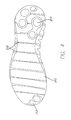
- FIG. 9 is a bottom view of the exemplary article of footwear of FIG. 8 according to an embodiment of the present invention.
- FIG. 10 is a side view of an exemplary midsole according to an embodiment of the present invention.
- FIG. 11 is a bottom view of an exemplary foot plate according to an embodiment of the present invention.
- FIG. 12 is a partial side view of the exemplary foot plate of FIG. 11 according to an embodiment of the present invention.
- FIG. 13 is a schematic view of an exemplary article of footwear during manufacturing according to an embodiment of the present invention.
- FIG. 14 is a side view of an exemplary article of footwear according to an embodiment of the present invention.
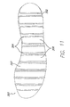
- FIG. 15 is a bottom view of the exemplary article of footwear of FIG. 14 according to an embodiment of the present invention.
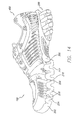
- FIG. 16 is a side view of an exemplary article of footwear according to an embodiment of the present invention.
- FIG. 17 is a bottom view of the exemplary article of footwear of FIG. 16 according to an embodiment of the present invention.
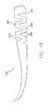
- FIG. 18 is a side view of an exemplary midsole for use in the exemplary article of footwear of FIG. 16 according to an embodiment of the present invention.
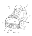
- FIG. 19 is front perspective cross-sectional view of an exemplary article of footwear according to an embodiment of the present invention.
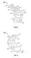
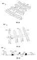
- FIG. 20 is a top perspective view of an insert according to an embodiment of the present invention.
- FIG. 21 is a bottom perspective view of the insert shown in FIG. 20 according to an embodiment of the present invention.
- FIG. 22 is a side view of the insert shown in FIG. 20 according to an embodiment of the present invention.
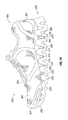
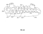
- FIG. 23 is a top perspective view of a midsole with an insert according to an embodiment of the present invention.
- FIG. 24 is a side view of an article of footwear with an insert according to an embodiment of the present invention.
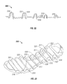
- FIG. 25 is a side view of an insert according to an embodiment of the present invention.
- FIG. 26 is a side view of an insert according to another embodiment of the present invention.
- FIG. 27 is a side view of an insert according to another embodiment of the present invention.
- FIG. 28 is a top perspective view of an insert according to another embodiment of the present invention.
- FIG. 29 is a bottom perspective view of the insert shown in FIG. 29 according to an embodiment of the present invention.
- FIG. 30 is a side view of an insert having solid support elements according to an embodiment of the present invention.
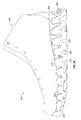
- FIG. 31 is a schematic view of an exemplary mold for manufacturing a sole according to an embodiment of the present invention.
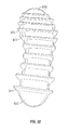
- FIG. 32 is a schematic view of exemplary post-molding form for manufacturing a sole according to an embodiment of the present invention.
- FIG. 33 a schematic view of an exemplary sole during manufacturing according to an embodiment of the present invention.
- FIG. 34 is a side view of an exemplary article of footwear according to an embodiment of the present invention.
- FIG. 35 is a bottom view of an exemplary article of footwear and outsole according to an embodiment of the present invention.
- An article of footwear 100 may have a sole 200 that undulates to provide a different and unique ride and/or feel to article of footwear 100 while also providing a unique aesthetic appeal and providing training for the wearer's muscles in the legs, lower back, and/or abdomen.
- a foot plate 300 is attached to undulating sole 200 and an upper 400 is attached to foot plate 300.
- Sole 200 may include a midsole 202 having an undulating shape with alternating peaks 204 and troughs 206.
- the undulating shape of midsole 202 may be substantially sinusoidal, whereby one or more of the peaks and/or troughs may be rounded.
- one or more of the peaks and/or troughs may have a top surface that is substantially flat, as shown for example, in FIG. 34 .
- the undulating shape of midsole 202 may be zigzagged, whereby one or more of the peaks and/or troughs may be pointed.
- peaks 204 may be located substantially equidistant between adjacent troughs 206, and similarly, troughs 206 may be located substantially equidistant between adjacent peaks. Between each peak 204 and each trough 206 may be a wall 208. Gaps 210 devoid of material may be present between adjacent peaks 204 and above a trough 206 and gaps 212 devoid of material may be present between adjacent troughs 206 and below a peak 204. Gaps 210 and gaps 212 may extend across an entire width of midsole 202. In an alternative embodiment, gaps 210 and gaps 212 may extend only along a portion of midsole 202. In one embodiment, the undulating shape of midsole 202 may be substantially similar to a sine wave. A distance between adjacent peaks 204 or adjacent troughs 206 may be substantially similar or may be varied along a length of midsole 202 or combinations thereof.
- Midsole 202 may be designed such that each trough 206 contacts or engages the ground separately when a user is walking, running, or otherwise moving under his/her own power. As each trough 206 contacts or engages the ground a compressive force is exerted causing distortion of the shape of gap 210 located above trough 206 as a result of vertical buckling of walls 208 connected to trough 206. The compressive forces can also distort the shape of gaps 212 on either side of trough 206 to increase the distance between the trough 206 contacting or engaging the ground and those adjacent to it. Shear forces exerted on midsole 202 may have the same effect of buckling walls 208 and distorting the shape of gaps 210 and 212.
- midsole 202 must be sufficiently flexible to allow the buckling and distortions described above so as to provide adequate cushioning.
- Suitable material for midsole 202 may include, but is not limited to, foam and thermoplastic polyurethane.
- the foam may be, for example, ethyl vinyl acetate (EVA) based or polyurethane (PU) based and the foam may be an open-cell foam or a closed-cell foam.
- midsole 202 may be elastomers, thermoplastic elastomers (TPE), foam-like plastic (e.g., Pebax® foam or Hytrel® foam) and gel-like plastics.
- midsole 202 that uniquely absorb the compressive and shear forces may include the: (1) tall, thin shape of walls 208, (2) angles between adjacent walls 208 of undulating midsole 202, (3) gaps 210 and 212 void of material on either side of walls 208; and/or (4) compression of the foam itself (aside from distortion of the sole geometry). Buckling may occur due to tall, thin walls 208. The voids of material or gaps 210, 212 may allow for the buckling and/or distention of the material of midsole 202 to occur when loaded. The contact of midsole 202 on the ground in the midfoot region may provide a new ride to the shoe.
- the heel strike may take a prolonged amount of time compared to a typical running shoe, which can decrease the peak forces.
- a force is applied to the midsole, not only does the midsole material compress, but the physical shape of the midsole may also change to absorb the compressive and shear forces.
- the physical changes in shape, and/or the buckling which may include walls 208 distending into one of the voids of material or gaps 210, 212 on either side of the wall, may occur because of the tall, thin shape of walls 212, angles between walls 208 of the undulating midsole 202, and/or voids of material or gaps 210, 212 on either side of walls 208.
- the unique shape, midsole contact with the ground in the midfoot region, and/or material may vary the amount of time spent in each phase of the gait cycle for an individual compared to a more traditional running shoe, possibly decreasing the peak force experienced by that individual.
- midsole 202 may cause the wearer's body to work harder.
- the shoe may trigger increased training to the muscles, such as those muscles in the wearer's calves, thighs, lower back, buttocks, and/or abdomen.
- forces acting on midsole 202 may cause the wearers' body to work less hard.
- midsole 202 may be adapted to enhance the natural resiliency and energy return of the foot by storing energy during its compression and returning energy during its expansion. As a result, muscles used during an activity may undergo less wear.
- Walls 208 may be contoured to provide gaps 210 and gaps 212 with a variety of shapes in order to impart varying cushioning effects. In one embodiment, as shown for example in FIGs. 1 and 6 , gaps 210 may be substantially v-shaped.
- the angle provided between adjacent walls 208 may be adapted to provide the desired cushioning properties. For example, in one embodiment the angle between adjacent walls 208 may be in the range of from about 10 degrees to about 50 degrees, such as from about 10 degrees to about 40 degrees or about 15 degrees to about 35 degrees. In one embodiment, the angle between adjacent walls may vary along the length of midsole 202.
- the angle may be greater between one or more pair of adjacent walls 208 in the heel portion of midsole 202 and lesser between one or more pair of adjacent walls 208 in the forefoot portion.
- the angle between adjacent walls 208 in the forefoot portion may be from about 30 to about 40 degrees.
- the angle between adjacent walls 208 in the heel portion may be from about 15 to about 25 degrees.
- gaps 212 may be substantially shaped as an inverted v.
- the depth of gaps 210 and 212 may also be varied to provide the desired cushioning properties.
- the depth of gaps 210 may vary along the length of midsole 202.
- gaps 210 may be deeper in the heel region of midsole 202, and become more shallow toward the forefoot region of midsole 202.
- gaps 212 may be substantially omega-shaped ( ⁇ ) such that each gap 212 has a rounded top section and a narrow bottom section wherein the distance d1 between the surface of the two walls 208 forming and facing each gap 212 is shorter at the bottom of gap 212 than a distance d2 in a middle portion of gap 212.
- the embodiments described above are merely exemplary and gaps 210 and gaps 212 may have any combination of shapes as would be apparent to one of ordinary skill in the art.
- midsole 202 may include a combination of v-shaped and omega-shaped gaps.
- midsole 202 may include ten gaps 210.
- midsole 202 may include in the range of two to fifteen gaps.
- midsole 202 may include in the range of five to thirteen gaps.
- midsole 202 may include in the range of eight to twelve gaps.
- midsole 202 may include at least five gaps.
- midsole 202 may include at least eight gaps.
- midsole 202 may include at least ten gaps.
- the number of gaps 210 and 212 may vary depending upon a thickness of walls 208, a frequency of the undulation, and/or the angle between adjacent walls 208.
- One or more troughs 206 of midsole 202 may have an outsole piece 213 attached thereto to provide additional traction.
- Outsole piece 213 may be rubber or any suitable material typically utilized for an outsole.
- a trough 206 may have one or more outsole pieces 213.
- outsole piece 213 may contact one or more troughs 206 and span a portion of gap 212 between adjacent troughs 206.
- FIG. 4 shows that shows for example in FIG.
- midsole 202 may have an outsole piece 213 that covers a periphery of a heel region of midsole 202 and/or another outsole piece 213 that covers a periphery of a forefoot region of midsole 202.
- Outsole piece 213 spans gaps 212 between adjacent troughs 206 and may include areas of reduced thickness 217 that allow outsole piece 213 to flex and lengthen when gaps 212 lengthen.
- Outsole pieces 213 may be made from a suitable polymeric material that permits the above-described lengthening and flexing.
- the above embodiments are merely exemplary and one skilled in the art would readily appreciate the pattern of outsole piece(s) 213 on trough(s) 206 of midsole 202 may have a variety of configurations.
- a bottom surface 215 of each trough 206 may have a contour that varies across a width of midsole 202.
- Bottom surface 215 of each trough 206 may have the same contour and/or shape, varying contours and/or shapes and combinations thereof.
- shape and pattern of outsole piece(s) 213 may correspond to the contour or shape of bottom surfaces 215 of troughs 206.
- Midsole 202 may be a single piece, as shown for example in FIGs. 2 and 4 , or may comprise two or more pieces.
- midsole 202 may have a lateral midsole piece 214 extending along a lateral side of article of footwear 100 and a medial midsole piece 216 extending along a medial side of article of footwear 100 with a space 218 located between lateral midsole piece 214 and medial midsole piece 216.
- a forefoot outsole piece 220 may be attached to both lateral midsole piece 214 and medial midsole piece 216 in a manner such that forefoot outsole piece 220 spans and covers a portion of space 218 at the forefoot of article of footwear 100.
- a heel outsole piece 222 may be attached to both lateral midsole piece 214 and medial midsole piece 216 in a manner such that heel outsole piece 222 spans and covers a portion of space 218 at the heel of article of footwear 100.
- Lateral midsole piece 214 and medial midsole piece 216 may have corresponding undulations such that peaks 204 and troughs 206 of each piece are aligned when assembled in article of footwear 100.
- Having a separate lateral midsole piece 214 and medial midsole piece 216 may have the advantage of providing a ride or cushioning different from a single piece midsole 202.
- midsole 202 may be shaped so that peaks 204 have a greater height at first and second sides 224, 226 of midsole 202 than in an area between first and second sides 224, 226.
- a top surface 228 of each peak 204 is substantially concave, thereby providing a recess for receiving foot plate 300.
- top surface 228 of some peaks 204 may have a groove 230 adjacent first and/or second sides 224, 226 that aids in aligning foot plate 300 in the recess and holding foot plate 300 in place.
- the portion of the midsole between the first and second sides 224, 226 does not undulate and only first (e.g., lateral) side 224 and/or second (e.g., medial) side 226 undulate. Portions of gaps 210 and/or 212 between first and second sides 224 and 226 may be filled in.
- Foot plate 300 may have a bottom surface 302 with a plurality of ridges 304 extending outward from bottom surface 302.
- Ridges 304 may be shaped to provide outlines that correspond to the size, shape, and contour of top surfaces 228 of peaks 204 of midsole 202. Ridges 304 may also extend to side surfaces 306 of foot plate 300. Accordingly, ridges 304 aid in aligning foot plate 300 on top surfaces 228 of peaks 204 of midsole 202.
- Foot plate 300 may be any suitable thermoplastic material or composite material and, in some embodiments, may be manufactured through molding or lay-up.
- foot plate 300 may be a molded foam, such as a compression molded foam, TPU, or Pcbax®.
- foot plate 300 may be formed separately from midsole 202 and then attached and joined to midsole 202 through adhesive bonding, welding, or other suitable techniques as would be apparent to one of ordinary skill in the art. Areas 308 of bottom surface 302 that contact top surfaces 228 of peaks 204 may be textured to facilitate attachment of foot plate 300 to midsole 202.
- foot plate 300 and midsole 202 may be co-molded and thereby formed together simultaneously.
- Midsole 202 may be used in conjunction with a variety of uppers 400.
- upper 400 may have a bootie 402 for receiving the foot of a wearer attached to an upper surface (not shown) of foot plate 300.
- plate 300 may be placed inside shoe 100 and midsole 202 may be attached directly to upper 400.
- Bootie 402 may be any suitable material that is lightweight and breathable known to those of ordinary skill in the art for use as an upper. Bootie 402 may be attached to the foot plate through adhesive or other conventional attachment techniques.
- Upper 400 may also have one or more structural members 404 extending from foot plate 300. Structural members 404 provide structure to bootie 402 and may extend along the lateral and medial sides and be utilized in lacing article of footwear 100.
- Structural members 404 may also be present at a heel area to provide an internal or external heel counter or at a forefoot area to provide an internal or external toe cap. Structural members 404 may be molded from suitable polymeric materials known to those of ordinary skill in the art. Structural members 404 may also have a variety of shapes and sizes as would be apparent to one of ordinary skill in the art.
- midsole 202 may be molded by injection molding using one or more molds 600.
- the mold 600 may include molds for one or more midsoles 202.
- mold 600 may include a plurality of ridges 601 which correspond to the one or more gaps 212 of midsole 202.
- injection sites or sprue passages 601 may be used to introduce midsole material into the mold. As shown in FIGs.
- eleven (11) sprues may be used to introduce material into the mold, thereby resulting in posts 232, which will be subsequently removed, extending from midsole 202 in the areas corresponding to the sprues. In this manner, the material may be distributed evenly throughout the midsole.
- one sprue may be used in the area of the rearmost peak, and two spruces may be used at each of the next two peaks in the heel region. Two sprues may also be used at each of the fifth, seventh, and ninth peaks in midsole 202.
- one or more sprues may be used at each of the peaks to introduce the midsole material to the mold.
- sprues for introducing midsole material into the mold may be useful because sprues may provide for even flow of material; may help to provide proper curing of material; may help to provide even temperature distribution after filling which, in turn, may contribute to consistent skin thickness; may help to make midsoles that are consistent left to right; and may help to make sure the mold is fully filled.
- Other arrangements for introducing material into the molds during manufacture of midsole 202 may be used.
- other methods of molding may be utilized including, but not limited to, compression molding, injection molding, and expansion molding, whereby pellets are placed in a mold and expanded.
- the mold may comprise a smaller size than the desired size of the midsole.
- the mold may comprise about 65% to about 75% of the size of the finished midsole. Depending on the expansion ratio of the material used, other mold sizes may be used.
- one or more post-molding forms 610 may be used after midsole 202 is removed from mold 600 during manufacturing. After removal from mold 600, top surface of midsole 202 may be placed on top of post-molding form 610.
- Post-molding form 610 may include a plurality of ridges 611 formed on a base 612 which correspond to the one or more gaps 210 of midsole 202.
- bottom surface of midsole 202 may be placed on top of post-molding form 610, and ridges 611 may correspond to one or more gaps 212 of midsole 202.
- Post-molding form 610 may facilitate proper cooling and shaping of midsole 202.
- midsole 202 may contract as it cools and/or finishes curing. Because the form is dimensionally stable, post-molding form 610 may limit and/or direct the contraction of the midsole 202 such that the midsole results in the desired shape. In some but not necessarily all embodiments, portions of midsole 202 may have varying thicknesses and/or may cool at different rates. As a result, midsole 202 may curl or otherwise become misshapen without use of post-molding form 610.
- one or more weights 620 may be placed on midsole 202 as it cools to further facilitate proper cooling and shaping. In one embodiment, a weight 620 may be placed on midsole 202 in the heel area and in the forefoot area of the midsole.
- Post-molding form 610 may comprise plastic, ceramic, metal, wood, bamboo, cast epoxy, or other suitable material.
- Midsole 202 may be molded to tailor to various needs such as, for example, to prevent pronation or supination. In such instances, certain areas of midsole 202 may be imparted with different characteristics in order to achieve such customizations. In instances where a medial side of midsole 202 needs to be customized and not a lateral side or vice versa, it may be preferred to utilize a midsole 202 with lateral midsole piece 214 and medial midsole piece 216, as described above. As an alternative to, or in addition to, modifying midsole 202, inserts may be placed between midsole 202 and plate 300, as discussed in more detail below, or posts may be utilized to connect midsole 202 to upper 400.
- midsole 202 may undulate with peaks 204 and troughs 206 only in a forefoot region. In other embodiments, as shown for example in FIGs. 16-18 , midsole 202 may undulate with peaks 204 and troughs 206 only in a heel region. In other embodiments, as shown for example in FIG. 19 , midsole 202 may also have one or more rows 334 that undulate with peaks 204 and troughs 206 in a medial to lateral direction. In some embodiments, peaks 204 and troughs 206 of each row 334 may be aligned.
- undulating sole 200 may be manufactured to provide a different and unique ride and/or feel to article of footwear 100, while also providing a unique aesthetic appeal and improved cushioning and support.
- embodiments of the present invention may include one or more inserts 500 to provide the desired stiffness and/or cushioning properties of midsole 202.
- one or more inserts 500 may be included to make all or a portion of midsole 202 more stiff. In this manner, for example, insert 500 may help in limiting pronation or supination of the foot of the wearer.
- insert 500 may include one or more support elements 510 connected by connecting members 520.
- support element 510 includes a support surface 511 that is curved such that the support element 510 is substantially u-shaped, as shown, for example, in FIG. 22 .
- support clement 510 may include a proximate end 512 and a distal end 514. The proximate end 512 may be rounded and the height of support element 510 may gradually decrease from proximate end 512 to distal end 514.
- Each support element 510 may be connected to an adjacent support element 510 by a connecting member 520.
- connecting member 520 extends from the distal end 514 of one support element 510 to the distal end 514 of an adjacent support element 510.
- connecting member 520 may extend from the distal end 514 of a first support element 510 to the proximate end 512 of an adj acent support clement.
- the connecting member 520 may extend from any point along the length of a first support clement 510 to any point along the length of an adjacent support element 510.
- Connecting member 520 may connect support elements that are not adjacent.
- support elements 510 disposed at an end of the insert 500 may include a connecting member 522 that does not connect to an adjacent support element.
- forefoot end support element 516 and rearfoot end support element 518, as shown in FIG. 20 may include a connecting member 522 that is not connected at one end.
- insert 500 may not include connecting members 522 extending from end support elements.
- insert 500 may include five (5) connected support elements 510.
- other combinations of support elements 510 and connecting members 520 for an insert 500 may be used to provide the desired stiffness and/or cushioning of midsole 202.
- insert 500 may be disposed between midsole 202 and plate 300 and may be coupled to midsole 202.
- each support element 510 of insert 500 may be disposed within a gap 210 of midsole 202.
- each of the support elements 510 may be disposed in a gap 210.
- the support surface 511 of support element 510 is preferably contoured to fit snugly within gap 210 along an interior surface 211 of the gap 210.
- the support surface 211 may cover all or a portion of the interior surface 211 of the gap 210 where the support clement 510 is located.
- support surface 511 may extend from the bottom 207 of gap 210 partially (e.g., half way) up interior wall 209 or to the top of interior wall 209.
- support element 510 may not extend completely into gap 210 such that it does not contact the bottom 207 of gap 210.
- the support surface 511 may cover only a portion of interior wall 209 between bottom 207 and the top of interior wall 209.
- support surface 511 is curved such that the support element 510 is substantially u-shaped. In other embodiments, support surface 511 may be square, v-shaped, omega-shaped, or otherwise shaped to fit within gap 210 or other portion of midsole 202. In one embodiment, support element 510 may be secured within gap 210 by adhesive. In other embodiments, adhesive may not be used and the snug fit of the element within the gap may keep it in place.
- insert 500 may be generally disposed in the arch region of midsole 202. In other embodiments, insert 500 may be disposed in the forefoot region, the heel region, and/or along the entire length of midsole 202. Generally, insert 500 may be positioned to provide the desired stiffness and/or cushioning of midsole 202.
- the size of support element 510 also may be adapted such that support element 510 fits within gap 210.
- the size of support elements 510 may likewise vary along insert 500.
- gaps 210 may be deeper in the heel region of midsole 202, and become more shallow toward the forefoot region of midsole 202.
- support elements 510 may be larger in the rearward portion of insert 500 and become smaller toward the forward portion of insert 500.
- forefoot end support element 516 may be smaller than rearfoot end support element 518.
- Insert 500 may be made of a rigid or flexible material to provide the desired stiffness properties of the midsole 202.
- the insert 500 comprises TPU.
- suitable materials including but not limited to, elastomers, thermoplastic elastomers (TPE), foam-like plastics (e.g., Pebax® foam and/or Hytrel® foam), gel-like plastics, foam, metal, or other suitable materials and combinations thereof.
- insert 500 may be injection molded as a unitary piece.
- support elements 510 may be molded separately and then attached.
- one support element 510 may be made of a different material than another support element 510.
- a first support element 510 may be made of a stiffer material than a second support element 510 to provide the desired stiffness or cushioning properties to different areas of midsole 202.
- insert 500 may be co-molded with midsole 202.
- insert 500 may be molded and midsole 202 may be molded under insert 500, or insert 500 may be molded directly on midsole 202. In one embodiment, as shown for example in FIG.
- support elements 510 may be formed as part of midsole 202 to form a unitary and monolithic structure.
- Support elements 510 may be formed in gaps 212, as shown, and/or in gaps 210.
- two support elements 510 may be formed in the rearmost gap 212 and one support element may be formed in the next gap 212. It will be appreciated that support elements 510 may be formed in other gaps in various combinations.
- midsole 202 may be molded around insert 500 such that insert 500 is embedded in the midsole.
- insert 500 may be integral with plate 300. The plate 300 may extend partially or completely into support element 510.
- one or more support elements 510 of insert 500 may extend across a portion of the width of the midsole 202 to provide desired stiffness properties to a portion of midsole 202.
- support elements 510 may extend inwardly from the medial side of the midsole 202 across a portion of the width of midsole 202.
- support element 510 may provide support to midsole 202 in'this area and may limit compression of the midsole.
- support element 510 may limit compression of the walls 208 around the area of the support element.
- insert 500 may impart additional stiffness to the medial side of midsole 202 and may limit, for example, supination of the foot.
- the support elements may extend inwardly from the lateral side of the midsole 202 across a portion of the midsole. In this manner, insert 500 may impart additional stiffness to the lateral side of midsole 202 and may, for example, limit pronation of the foot. In still other embodiments, the insert 500 may extend substantially across the entire width of the midsole 202 such that it may impart desired stiffness or cushioning characteristics across the width of the midsole. In some embodiments, insert 500 may include one or more support elements 510 that extend only across a portion of the width of midsole 202 and one or more support elements 510 that extend across the entire width of midsole 202.
- connecting member 520 may be substantially flat such that it does not interfere with placement of plate 300 on midsole 202.
- a groove may be formed in the top of midsole 202 to receive connecting member 520 such that connecting member 520 is flush with the top of midsole 202.
- connecting members 520 of insert 500 may collectively form a generally curved shape from the perimeter of midsole 202 through an interior portion of the midsole 202. In one embodiment, connecting members 520 may be positioned to provide additional support to the insert 500.
- all or a portion of the insert 500 may be visible from the side of footwear 100.
- proximate end 512 of one or more support elements 510 may be visible through gaps 210.
- insert 500 may not be visible.
- insert 500 may include two (2) support elements 510.
- the support elements 510 may be sized for use in the heel portion of midsole 202.
- insert 500 may include two (2) support elements 510 generally sized for use in the forefoot portion of the midsole 202.
- insert 500 may include one support element.
- insert 500 may comprise a single support element 510 without connecting members 520. As shown in FIGs.
- insert 500 may include four (4) support elements 510 that extend substantially across the width of the midsole 202.
- Connecting members 520 may connect adjacent support elements 520 at the middle of the support element.
- the number of support elements 510 may be the same as the number of gaps 210 in midsole 202.
- insert 500 may be disposed on the underside of midsole 202.
- Each support element 510 of insert 500 may be disposed within gap 212 of midsole 202.
- the support elements 510 may be sized and shaped accordingly.
- insert 500 may include one or more support elements 510 adapted to fit snugly on peak 204.
- insert 500 may be permanently disposed in midsole 202 during manufacture of footwear 100.
- insert 500 may be readily removable from midsole 202.
- a support element 510 may be inserted into gap 210 between midsole 202 and plate 300 from the side of footwear 100.
- the support element 510 may include a tab that may be pulled to subsequently remove the support element 510 from gap 210.
- inserts 500 or support elements 510 may be sold "after-market", and a user may continually customize the stiffness or cushioning properties of footwear 100 depending on desired uses, aging of the shoe, or other conditions of use.
- one or more support elements 510 may be solid elements.
- a support element 510 may be completely solid, as shown by support element 513, or may be partially solid, as shown by support elements 515 and 517.
- the solid support elements may be filled with the same material as the support surface 511 and formed as a unitary piece, or may be filled with a different material, such as, for example, foam or other suitable material.
- support element 510 may be filled with a portion of plate 300.
- the solid support elements may be adapted to provide additional support to midsole 202.
- support element 510 may be hollow, fluid filled, or filled with pressurized or ambient air.
Abstract
Description
- The present invention is directed to an article of footwear having an undulating sole.
- Individuals are often concerned with the amount of cushioning an article of footwear provides, as well as the aesthetic appeal of the article of footwear. This is true for articles of footwear worn for non-performance activities, such as a leisurely stroll, and for performance activities, such as running, because throughout the course of an average day, the feet and legs of an individual are subjected to substantial impact forces. Running, jumping, walking, and even standing exert forces upon the feet and legs of an individual which can lead to soreness, fatigue, and injury.
- The human foot is a complex and remarkable piece of machinery, capable of withstanding and dissipating many impact forces. The natural padding of fat at the heel and forefoot, as well as the flexibility of the arch, help to cushion the foot. Although the human foot possesses natural cushioning and rebounding characteristics, the foot alone is incapable of effectively overcoming many of the forces encountered during every day activity. Unless an individual is wearing shoes which provide proper cushioning and support, the soreness and fatigue associated with every day activity is more acute, and its onset accelerated. The discomfort for the wearer that results may diminish the incentive for further activity. Equally important, inadequately cushioned footwear can lead to injures such as blisters; muscle, tendon and ligament damage; and bone stress fractures. Improper footwear can also lead to other ailments, including back pain.
- Proper footwear should complement the natural functionality of the foot, in part, by incorporating a sole (typically including an outsole, midsole and insole) which absorbs shocks. Therefore, a continuing need exists for innovations in providing cushioning to articles of footwear.
- In one embodiment, an article of footwear includes an undulating foam sole. The undulating foam sole includes a plurality of spaced apart peaks, wherein at least one pair of adjacent peaks define a gap void of material between adjacent peaks, and a plurality of spaced apart troughs, wherein at least one trough is adapted to engage the ground and wherein at least one pair of adjacent troughs define a gap void of material between adjacent troughs.
- In another embodiment, an article of footwear includes an undulating foam midsole. The undulating midsole includes a first side, a second side, a plurality of spaced apart peaks extending along a width of the midsole between the first and second sides, and a plurality of spaced apart troughs extending along a width of the midsole between the first and second sides. At least one pair of adjacent peaks define a gap void of material between the adjacent peaks that extends along the width of the midsole with one end at the first side and another end at the second side. At least one pair of adjacent troughs define a gap void of material between the adjacent troughs that extends along the width of the midsole with one end at the first side and another end at the second side.
- In a further embodiment, an article of footwear includes an undulating midsole and a plate. The undulating midsole includes a first side, a second side, a plurality of spaced apart peaks extending along a width of the midsole between the first and second sides, and a plurality of spaced apart troughs extending along a width of the midsole between the first and second sides, The plate is attached to the plurality of spaced apart peaks. Each of the plurality of spaced apart peaks has a greater height at the first and second sides of the midsole than in an area between the first and second sides.
- In a further embodiment, an article of footwear includes an upper; a plate connected to the upper; and an undulating sole having a top surface connected to the plate and a bottom surface, the sole comprising a plurality of spaced apart peaks defining a plurality of gaps in the top surface and a plurality of spaced apart troughs defining a plurality of gaps in the bottom surface. The article of footwear may further comprise one or more support elements coupled to the sole for providing support thereto. The support element may be disposed between the sole and the plate. In one embodiment, the support element may be disposed in a gap in the top surface of the sole.
- In a further embodiment, a sole for an article of footwear includes a midsole having a heel portion, a forefoot portion, a medial sidewall and a lateral sidewall, and wherein the midsole is substantially sinusoidal along at least a portion of the length of the midsole, and wherein the midsole extends along a width of the midsole. It will be appreciated by those of ordinary skill in the art that the terms sinusoidal and sine wave as used herein refer to the undulating shape of the midsole and are not meant to be used in a strict mathematical sense. In one embodiment, the midsole may extend across the entire width of the midsole between the medial sidewall and the lateral sidewall and may have a top surface shaped to receive an upper of an article of footwear. The midsole may be substantially sinusoidal along a portion of, or substantially the entire length of, the midsole. In one embodiment, the lateral sidewall and/or the medial sidewall may be substantially sinusoidal. In another embodiment, the midsole may be substantially sinusoidal across the entire width of the midsole. The lateral and/or medial sidewalls may include a plurality of peaks having rounded top surfaces, flat top surfaces, pointed top surfaces, or combinations thereof. The midsole may comprise foam, and an outsole may be coupled to the midsole.
- In yet a further embodiment, a sole for an article of footwear includes a midsole having a top surface, a bottom surface, a medial sidewall, and a lateral sidewall, wherein the midsole undulates to define a plurality of spaced apart gaps in the top surface and a plurality of spaced apart gaps in the bottom surface. Each of a plurality of top surface gaps may be disposed between adjacent bottom surface gaps. In one embodiment, the top surface gaps and/or the bottom surface gaps may be substantially evenly spaced apart. In one embodiment, one or more gaps extend across the entire width of the midsole. In one embodiment, the lateral and/or medial sidewalls include a plurality of peaks and each peak is disposed between adjacent top surface gaps. The lateral and/or medial sidewalls may include a plurality of peaks having rounded top surfaces, flat top surfaces, pointed top surfaces, or combinations thereof. In one embodiment, the midsole extends across the entire width of the sole between the medial sidewall and the lateral sidewall. In one embodiment, the portion of the midsole between the medial sidewall and the lateral sidewall does not undulate. In one embodiment, one or more gaps extend across the entire width of the midsole and/or only a portion of the width of the midsole.
- In another embodiment, an article of footwear includes an upper; and a foam sole disposed below the upper such that a gap is disposed between the sole and the upper, the sole having a heel portion, a forefoot portion, a medial sidewall and a lateral sidewall, and wherein the sole is substantially sinusoidal along the length of the sole, and wherein the sole extends along a width of the sole. In one embodiment, a plurality of gaps may be disposed between the sole and the upper. The lateral and/or medial sidewall may include a plurality of peaks having rounded top surfaces, flat top surfaces, or pointed top surfaces. In one embodiment the article of footwear may further include a plate disposed intermediate to the upper and the sole. At least a portion of a gap may be disposed intermediate to the sole and the plate.
- In another embodiment, a method of manufacturing a sole for an article of footwear includes the steps of molding an undulating foam midsole in a mold; removing the foam midsole from the mold; placing the foam midsole on a form having a plurality of spaced apart ridges; and cooling the foam midsole. The mold may comprise a plurality of spaced apart ridges and at least one injection site disposed between two adjacent ridges. In one embodiment, the mold may include between one and twenty injection sites. In one embodiment, the mold may include eleven injection sites.
- In another embodiment, an article of footwear includes an undulating foam sole, which includes: a plurality of spaced part peaks, wherein at least one pair of adjacent peaks define a first gap substantially devoid of material between adjacent peaks, and a plurality of spaced apart troughs, wherein at least one pair of adjacent troughs define a second gap substantially devoid of material between adjacent troughs; and a support element coupled to the sole for providing support thereto.
- In a further embodiment, an article of footwear includes an upper; a plate connected to the upper; an undulating sole having a top side connected to the plate and a bottom side, the sole comprising a plurality of spaced apart peaks defining a plurality of gaps in the top side and a plurality of spaced apart troughs defining a plurality of gaps in the bottom side; and a support element disposed in between the sole and the plate for providing support to the sole.
- The accompanying drawings, which are incorporated herein and form a part of the specification, illustrate the present invention and, together with the description, further serve to explain the principles of the invention and to enable a person skilled in the pertinent art to make and use the invention.
-
FIG. 1 is a side view of an exemplary article of footwear according to an embodiment of the present invention; -
FIG. 2 is bottom view of the exemplary article of footwear ofFIG. 1 according to an embodiment of the present invention; -
FIG. 3 is a side view of another exemplary article of footwear according to an embodiment of the present invention; -
FIG. 4 is a bottom view of the exemplary article of footwear ofFIG. 3 according to an embodiment of the present invention; -
FIG. 5 is a close up side view of a portion of a midsole of the exemplary article of footwear ofFIG. 3 according to an embodiment of the present invention; -
FIG. 6 is a side view of another exemplary article of footwear according to an embodiment of the present invention; -
FIG. 7 a bottom view of the exemplary article of footwear ofFIG. 6 according to an embodiment of the present invention; -
FIG. 8 is a side view of another exemplary article of footwear according to an embodiment of the present invention; -
FIG. 9 is a bottom view of the exemplary article of footwear ofFIG. 8 according to an embodiment of the present invention; -
FIG. 10 is a side view of an exemplary midsole according to an embodiment of the present invention; -
FIG. 11 is a bottom view of an exemplary foot plate according to an embodiment of the present invention; and -
FIG. 12 is a partial side view of the exemplary foot plate ofFIG. 11 according to an embodiment of the present invention. -
FIG. 13 is a schematic view of an exemplary article of footwear during manufacturing according to an embodiment of the present invention. -
FIG. 14 is a side view of an exemplary article of footwear according to an embodiment of the present invention. -
FIG. 15 is a bottom view of the exemplary article of footwear ofFIG. 14 according to an embodiment of the present invention. -
FIG. 16 is a side view of an exemplary article of footwear according to an embodiment of the present invention. -
FIG. 17 is a bottom view of the exemplary article of footwear ofFIG. 16 according to an embodiment of the present invention. -
FIG. 18 is a side view of an exemplary midsole for use in the exemplary article of footwear ofFIG. 16 according to an embodiment of the present invention. -
FIG. 19 is front perspective cross-sectional view of an exemplary article of footwear according to an embodiment of the present invention. -
FIG. 20 is a top perspective view of an insert according to an embodiment of the present invention. -
FIG. 21 is a bottom perspective view of the insert shown inFIG. 20 according to an embodiment of the present invention. -
FIG. 22 is a side view of the insert shown inFIG. 20 according to an embodiment of the present invention. -
FIG. 23 is a top perspective view of a midsole with an insert according to an embodiment of the present invention. -
FIG. 24 is a side view of an article of footwear with an insert according to an embodiment of the present invention. -
FIG. 25 is a side view of an insert according to an embodiment of the present invention. -
FIG. 26 is a side view of an insert according to another embodiment of the present invention. -
FIG. 27 is a side view of an insert according to another embodiment of the present invention. -
FIG. 28 is a top perspective view of an insert according to another embodiment of the present invention. -
FIG. 29 is a bottom perspective view of the insert shown inFIG. 29 according to an embodiment of the present invention. -
FIG. 30 is a side view of an insert having solid support elements according to an embodiment of the present invention. -
FIG. 31 is a schematic view of an exemplary mold for manufacturing a sole according to an embodiment of the present invention. -
FIG. 32 is a schematic view of exemplary post-molding form for manufacturing a sole according to an embodiment of the present invention. -
FIG. 33 a schematic view of an exemplary sole during manufacturing according to an embodiment of the present invention. -
FIG. 34 is a side view of an exemplary article of footwear according to an embodiment of the present invention -
FIG. 35 is a bottom view of an exemplary article of footwear and outsole according to an embodiment of the present invention. - The present invention is now described with reference to the Figures, in which like reference numerals are used to indicate identical or functionally similar elements. While specific configurations and arrangements are discussed, it should be understood that this is done for illustrative purposes only. A person skilled in the pertinent art will recognize that other configurations and arrangements can be used without departing from the spirit and scope of the present invention. It will be apparent to a person skilled in the pertinent art that this invention can also be employed in a variety of other applications.
- An article of
footwear 100 according to an embodiment of the present invention may have a sole 200 that undulates to provide a different and unique ride and/or feel to article offootwear 100 while also providing a unique aesthetic appeal and providing training for the wearer's muscles in the legs, lower back, and/or abdomen. Afoot plate 300 is attached to undulating sole 200 and an upper 400 is attached tofoot plate 300. -
Sole 200 may include amidsole 202 having an undulating shape with alternatingpeaks 204 andtroughs 206. In some embodiments, the undulating shape ofmidsole 202 may be substantially sinusoidal, whereby one or more of the peaks and/or troughs may be rounded. In other embodiments, one or more of the peaks and/or troughs may have a top surface that is substantially flat, as shown for example, inFIG. 34 . In other embodiments, the undulating shape ofmidsole 202 may be zigzagged, whereby one or more of the peaks and/or troughs may be pointed. In some embodiments,peaks 204 may be located substantially equidistant betweenadjacent troughs 206, and similarly,troughs 206 may be located substantially equidistant between adjacent peaks. Between each peak 204 and eachtrough 206 may be awall 208.Gaps 210 devoid of material may be present betweenadjacent peaks 204 and above atrough 206 andgaps 212 devoid of material may be present betweenadjacent troughs 206 and below apeak 204.Gaps 210 andgaps 212 may extend across an entire width ofmidsole 202. In an alternative embodiment,gaps 210 andgaps 212 may extend only along a portion ofmidsole 202. In one embodiment, the undulating shape ofmidsole 202 may be substantially similar to a sine wave. A distance betweenadjacent peaks 204 oradjacent troughs 206 may be substantially similar or may be varied along a length ofmidsole 202 or combinations thereof. -
Midsole 202 may be designed such that eachtrough 206 contacts or engages the ground separately when a user is walking, running, or otherwise moving under his/her own power. As eachtrough 206 contacts or engages the ground a compressive force is exerted causing distortion of the shape ofgap 210 located abovetrough 206 as a result of vertical buckling ofwalls 208 connected totrough 206. The compressive forces can also distort the shape ofgaps 212 on either side oftrough 206 to increase the distance between thetrough 206 contacting or engaging the ground and those adjacent to it. Shear forces exerted onmidsole 202 may have the same effect of bucklingwalls 208 and distorting the shape ofgaps - Accordingly, material for
midsole 202 must be sufficiently flexible to allow the buckling and distortions described above so as to provide adequate cushioning. Suitable material formidsole 202 may include, but is not limited to, foam and thermoplastic polyurethane. Whenmidsole 202 is a foam, the foam may be, for example, ethyl vinyl acetate (EVA) based or polyurethane (PU) based and the foam may be an open-cell foam or a closed-cell foam. In other embodiments,midsole 202 may be elastomers, thermoplastic elastomers (TPE), foam-like plastic (e.g., Pebax® foam or Hytrel® foam) and gel-like plastics. - Individually or in combination, the aspects of
midsole 202 that uniquely absorb the compressive and shear forces may include the: (1) tall, thin shape ofwalls 208, (2) angles betweenadjacent walls 208 of undulatingmidsole 202, (3)gaps walls 208; and/or (4) compression of the foam itself (aside from distortion of the sole geometry). Buckling may occur due to tall,thin walls 208. The voids of material orgaps midsole 202 to occur when loaded. The contact ofmidsole 202 on the ground in the midfoot region may provide a new ride to the shoe. The heel strike may take a prolonged amount of time compared to a typical running shoe, which can decrease the peak forces. When a force is applied to the midsole, not only does the midsole material compress, but the physical shape of the midsole may also change to absorb the compressive and shear forces. The physical changes in shape, and/or the buckling, which may includewalls 208 distending into one of the voids of material orgaps walls 212, angles betweenwalls 208 of the undulatingmidsole 202, and/or voids of material orgaps walls 208. The unique shape, midsole contact with the ground in the midfoot region, and/or material may vary the amount of time spent in each phase of the gait cycle for an individual compared to a more traditional running shoe, possibly decreasing the peak force experienced by that individual. - The above described effects of the compressive forces and shear forces on
midsole 202 may cause the wearer's body to work harder. By forcing the wearer's body to work harder, the shoe may trigger increased training to the muscles, such as those muscles in the wearer's calves, thighs, lower back, buttocks, and/or abdomen. As a result of this extra work, when a wearer travels a given distance, the affected muscles may feel like they have worked in traversing a distance farther than the given distance, thereby enhancing a wearer's amount of exercise. In another embodiment, forces acting onmidsole 202 may cause the wearers' body to work less hard. For example,midsole 202 may be adapted to enhance the natural resiliency and energy return of the foot by storing energy during its compression and returning energy during its expansion. As a result, muscles used during an activity may undergo less wear. -
Walls 208 may be contoured to providegaps 210 andgaps 212 with a variety of shapes in order to impart varying cushioning effects. In one embodiment, as shown for example inFIGs. 1 and6 ,gaps 210 may be substantially v-shaped. The angle provided betweenadjacent walls 208 may be adapted to provide the desired cushioning properties. For example, in one embodiment the angle betweenadjacent walls 208 may be in the range of from about 10 degrees to about 50 degrees, such as from about 10 degrees to about 40 degrees or about 15 degrees to about 35 degrees. In one embodiment, the angle between adjacent walls may vary along the length ofmidsole 202. For example, in one embodiment the angle may be greater between one or more pair ofadjacent walls 208 in the heel portion ofmidsole 202 and lesser between one or more pair ofadjacent walls 208 in the forefoot portion. For example, in some embodiments the angle betweenadjacent walls 208 in the forefoot portion may be from about 30 to about 40 degrees. In some embodiments the angle betweenadjacent walls 208 in the heel portion may be from about 15 to about 25 degrees. In another embodiment, as also shown for example inFIG. 1 ,gaps 212 may be substantially shaped as an inverted v. - The depth of
gaps FIG. 1 , the depth ofgaps 210 may vary along the length ofmidsole 202. For example,gaps 210 may be deeper in the heel region ofmidsole 202, and become more shallow toward the forefoot region ofmidsole 202. - In another embodiment, as shown for example in
FIGs. 3 and5 ,gaps 212 may be substantially omega-shaped (Ω) such that eachgap 212 has a rounded top section and a narrow bottom section wherein the distance d1 between the surface of the twowalls 208 forming and facing eachgap 212 is shorter at the bottom ofgap 212 than a distance d2 in a middle portion ofgap 212. The embodiments described above are merely exemplary andgaps 210 andgaps 212 may have any combination of shapes as would be apparent to one of ordinary skill in the art. For example, in oneembodiment midsole 202 may include a combination of v-shaped and omega-shaped gaps. - The number of
walls 208, and, correspondingly, the number ofgaps midsole 202 may vary depending upon the desired cushioning characteristics or upon the length and width ofmidsole 202. In one embodiment, as shown for example inFIG. 1 ,midsole 202 may include tengaps 210. In one embodiment,midsole 202 may include in the range of two to fifteen gaps. In another embodiment,midsole 202 may include in the range of five to thirteen gaps. In another embodiment,midsole 202 may include in the range of eight to twelve gaps. In one embodiment,midsole 202 may include at least five gaps. In another embodiment,midsole 202 may include at least eight gaps. In another embodiment,midsole 202 may include at least ten gaps. The number ofgaps walls 208, a frequency of the undulation, and/or the angle betweenadjacent walls 208. - One or
more troughs 206 ofmidsole 202 may have anoutsole piece 213 attached thereto to provide additional traction.Outsole piece 213 may be rubber or any suitable material typically utilized for an outsole. In one embodiment, as shown for example inFIGs. 2 and35 , atrough 206 may have one ormore outsole pieces 213. In another embodiment, as shown for example inFIG. 4 ,outsole piece 213 may contact one ormore troughs 206 and span a portion ofgap 212 betweenadjacent troughs 206. In another embodiment, as shown for example inFIG. 7 ,midsole 202 may have anoutsole piece 213 that covers a periphery of a heel region ofmidsole 202 and/or anotheroutsole piece 213 that covers a periphery of a forefoot region ofmidsole 202.Outsole piece 213 spansgaps 212 betweenadjacent troughs 206 and may include areas of reducedthickness 217 that allowoutsole piece 213 to flex and lengthen whengaps 212 lengthen.Outsole pieces 213 may be made from a suitable polymeric material that permits the above-described lengthening and flexing. The above embodiments are merely exemplary and one skilled in the art would readily appreciate the pattern of outsole piece(s) 213 on trough(s) 206 ofmidsole 202 may have a variety of configurations. In addition, as shown inFIGs. 2 ,4 ,7 , and9 , abottom surface 215 of eachtrough 206 may have a contour that varies across a width ofmidsole 202.Bottom surface 215 of eachtrough 206 may have the same contour and/or shape, varying contours and/or shapes and combinations thereof. One skilled in the art would readily appreciate that the shape and pattern of outsole piece(s) 213 may correspond to the contour or shape ofbottom surfaces 215 oftroughs 206. -
Midsole 202 may be a single piece, as shown for example inFIGs. 2 and4 , or may comprise two or more pieces. In one embodiment, as shown for example inFIG. 9 ,midsole 202 may have alateral midsole piece 214 extending along a lateral side of article offootwear 100 and amedial midsole piece 216 extending along a medial side of article offootwear 100 with aspace 218 located betweenlateral midsole piece 214 andmedial midsole piece 216. Aforefoot outsole piece 220 may be attached to bothlateral midsole piece 214 andmedial midsole piece 216 in a manner such thatforefoot outsole piece 220 spans and covers a portion ofspace 218 at the forefoot of article offootwear 100. Similarly, aheel outsole piece 222 may be attached to bothlateral midsole piece 214 andmedial midsole piece 216 in a manner such thatheel outsole piece 222 spans and covers a portion ofspace 218 at the heel of article offootwear 100.Lateral midsole piece 214 andmedial midsole piece 216 may have corresponding undulations such thatpeaks 204 andtroughs 206 of each piece are aligned when assembled in article offootwear 100. Having a separatelateral midsole piece 214 andmedial midsole piece 216 may have the advantage of providing a ride or cushioning different from asingle piece midsole 202. - As best seen in
FIG. 10 ,midsole 202 may be shaped so thatpeaks 204 have a greater height at first andsecond sides midsole 202 than in an area between first andsecond sides top surface 228 of each peak 204 is substantially concave, thereby providing a recess for receivingfoot plate 300. In one embodiment,top surface 228 of somepeaks 204 may have agroove 230 adjacent first and/orsecond sides foot plate 300 in the recess and holdingfoot plate 300 in place. In one embodiment, the portion of the midsole between the first andsecond sides side 224 and/or second (e.g., medial)side 226 undulate. Portions ofgaps 210 and/or 212 between first andsecond sides -
Foot plate 300, as best seen inFIGs. 11 and12 , may have abottom surface 302 with a plurality ofridges 304 extending outward frombottom surface 302.Ridges 304 may be shaped to provide outlines that correspond to the size, shape, and contour oftop surfaces 228 ofpeaks 204 ofmidsole 202.Ridges 304 may also extend to sidesurfaces 306 offoot plate 300. Accordingly,ridges 304 aid in aligningfoot plate 300 ontop surfaces 228 ofpeaks 204 ofmidsole 202. -
Foot plate 300 may be any suitable thermoplastic material or composite material and, in some embodiments, may be manufactured through molding or lay-up. In other embodiments,foot plate 300 may be a molded foam, such as a compression molded foam, TPU, or Pcbax®. In one embodiment,foot plate 300 may be formed separately frommidsole 202 and then attached and joined to midsole 202 through adhesive bonding, welding, or other suitable techniques as would be apparent to one of ordinary skill in the art.Areas 308 ofbottom surface 302 that contacttop surfaces 228 ofpeaks 204 may be textured to facilitate attachment offoot plate 300 tomidsole 202. In another embodiment,foot plate 300 andmidsole 202 may be co-molded and thereby formed together simultaneously. -
Midsole 202 may be used in conjunction with a variety ofuppers 400. In one embodiment, upper 400 may have abootie 402 for receiving the foot of a wearer attached to an upper surface (not shown) offoot plate 300. In some embodiments,plate 300 may be placed insideshoe 100 andmidsole 202 may be attached directly to upper 400.Bootie 402 may be any suitable material that is lightweight and breathable known to those of ordinary skill in the art for use as an upper.Bootie 402 may be attached to the foot plate through adhesive or other conventional attachment techniques.Upper 400 may also have one or morestructural members 404 extending fromfoot plate 300.Structural members 404 provide structure tobootie 402 and may extend along the lateral and medial sides and be utilized in lacing article offootwear 100.Structural members 404 may also be present at a heel area to provide an internal or external heel counter or at a forefoot area to provide an internal or external toe cap.Structural members 404 may be molded from suitable polymeric materials known to those of ordinary skill in the art.Structural members 404 may also have a variety of shapes and sizes as would be apparent to one of ordinary skill in the art. - With reference to
FIGs. 13 and31- 33 , manufacturing ofmidsole 202 according to embodiments of the present invention will now be described. As will be apparent to those of ordinary skill in the art,midsole 202 may be molded by injection molding using one ormore molds 600. Themold 600 may include molds for one ormore midsoles 202. With reference toFIGs. 13 and31 ,mold 600 may include a plurality ofridges 601 which correspond to the one ormore gaps 212 ofmidsole 202. During molding one or more injection sites orsprue passages 601 may be used to introduce midsole material into the mold. As shown inFIGs. 13 and31 , in one embodiment of the present invention, eleven (11) sprues may be used to introduce material into the mold, thereby resulting inposts 232, which will be subsequently removed, extending frommidsole 202 in the areas corresponding to the sprues. In this manner, the material may be distributed evenly throughout the midsole. In the heel portion ofmidsole 202, one sprue may be used in the area of the rearmost peak, and two spruces may be used at each of the next two peaks in the heel region. Two sprues may also be used at each of the fifth, seventh, and ninth peaks inmidsole 202. In another embodiment, one or more sprues may be used at each of the peaks to introduce the midsole material to the mold. The use of sprues for introducing midsole material into the mold may be useful because sprues may provide for even flow of material; may help to provide proper curing of material; may help to provide even temperature distribution after filling which, in turn, may contribute to consistent skin thickness; may help to make midsoles that are consistent left to right; and may help to make sure the mold is fully filled. Other arrangements for introducing material into the molds during manufacture ofmidsole 202 may be used. In some embodiments, other methods of molding may be utilized including, but not limited to, compression molding, injection molding, and expansion molding, whereby pellets are placed in a mold and expanded. - During manufacture, because
midsole 202 may expand upon removal from its mold, the mold may comprise a smaller size than the desired size of the midsole. For example, in one embodiment of the present invention using EVA material, the mold may comprise about 65% to about 75% of the size of the finished midsole. Depending on the expansion ratio of the material used, other mold sizes may be used. - With reference to
FIGs. 32 and33 , in one embodiment, one or morepost-molding forms 610 may be used aftermidsole 202 is removed frommold 600 during manufacturing. After removal frommold 600, top surface ofmidsole 202 may be placed on top ofpost-molding form 610.Post-molding form 610 may include a plurality ofridges 611 formed on a base 612 which correspond to the one ormore gaps 210 ofmidsole 202. In alternative embodiments, bottom surface ofmidsole 202 may be placed on top ofpost-molding form 610, andridges 611 may correspond to one ormore gaps 212 ofmidsole 202.Post-molding form 610 may facilitate proper cooling and shaping ofmidsole 202. For example,midsole 202 may contract as it cools and/or finishes curing. Because the form is dimensionally stable,post-molding form 610 may limit and/or direct the contraction of themidsole 202 such that the midsole results in the desired shape. In some but not necessarily all embodiments, portions ofmidsole 202 may have varying thicknesses and/or may cool at different rates. As a result,midsole 202 may curl or otherwise become misshapen without use ofpost-molding form 610. In one embodiment, one ormore weights 620 may be placed onmidsole 202 as it cools to further facilitate proper cooling and shaping. In one embodiment, aweight 620 may be placed onmidsole 202 in the heel area and in the forefoot area of the midsole.Post-molding form 610 may comprise plastic, ceramic, metal, wood, bamboo, cast epoxy, or other suitable material. -
Midsole 202 may be molded to tailor to various needs such as, for example, to prevent pronation or supination. In such instances, certain areas ofmidsole 202 may be imparted with different characteristics in order to achieve such customizations. In instances where a medial side ofmidsole 202 needs to be customized and not a lateral side or vice versa, it may be preferred to utilize amidsole 202 withlateral midsole piece 214 andmedial midsole piece 216, as described above. As an alternative to, or in addition to, modifyingmidsole 202, inserts may be placed betweenmidsole 202 andplate 300, as discussed in more detail below, or posts may be utilized to connectmidsole 202 to upper 400. - The embodiments of
FIGs. 1-4 and6-10 , have illustratedmidsole 202 as undulating withpeaks 204 andtroughs 206 from toe to heel, however this is merely exemplary. In some embodiments, as shown for example inFIGs. 14 and15 ,midsole 202 may undulate withpeaks 204 andtroughs 206 only in a forefoot region. In other embodiments, as shown for example inFIGs. 16-18 ,midsole 202 may undulate withpeaks 204 andtroughs 206 only in a heel region. In other embodiments, as shown for example inFIG. 19 ,midsole 202 may also have one or more rows 334 that undulate withpeaks 204 andtroughs 206 in a medial to lateral direction. In some embodiments,peaks 204 andtroughs 206 of each row 334 may be aligned. - In certain embodiments, undulating sole 200 may be manufactured to provide a different and unique ride and/or feel to article of
footwear 100, while also providing a unique aesthetic appeal and improved cushioning and support. - With reference to
FIGs. 20-22 , embodiments of the present invention may include one ormore inserts 500 to provide the desired stiffness and/or cushioning properties ofmidsole 202. For example, one ormore inserts 500 may be included to make all or a portion ofmidsole 202 more stiff. In this manner, for example, insert 500 may help in limiting pronation or supination of the foot of the wearer. - In one embodiment, insert 500 may include one or
more support elements 510 connected by connectingmembers 520. In one embodiment,support element 510 includes asupport surface 511 that is curved such that thesupport element 510 is substantially u-shaped, as shown, for example, inFIG. 22 . As shown inFIG. 20 , in oneembodiment support clement 510 may include aproximate end 512 and adistal end 514. Theproximate end 512 may be rounded and the height ofsupport element 510 may gradually decrease fromproximate end 512 todistal end 514. - Each
support element 510 may be connected to anadjacent support element 510 by a connectingmember 520. In one embodiment, connectingmember 520 extends from thedistal end 514 of onesupport element 510 to thedistal end 514 of anadjacent support element 510. In alternative embodiments, connectingmember 520 may extend from thedistal end 514 of afirst support element 510 to theproximate end 512 of an adj acent support clement. In other embodiments, the connectingmember 520 may extend from any point along the length of afirst support clement 510 to any point along the length of anadjacent support element 510. Connectingmember 520 may connect support elements that are not adjacent. In one embodiment,support elements 510 disposed at an end of theinsert 500 may include a connectingmember 522 that does not connect to an adjacent support element. For example, forefootend support element 516 and rearfootend support element 518, as shown inFIG. 20 , may include a connectingmember 522 that is not connected at one end. Alternatively, insert 500 may not include connectingmembers 522 extending from end support elements. In one embodiment, as shown, for example inFIGs. 20-22 , insert 500 may include five (5) connectedsupport elements 510. As will be discussed in detail below, other combinations ofsupport elements 510 and connectingmembers 520 for aninsert 500 may be used to provide the desired stiffness and/or cushioning ofmidsole 202. - With reference to
FIGs. 23 and24 , in one embodiment, insert 500 may be disposed betweenmidsole 202 andplate 300 and may be coupled tomidsole 202. In particular, in one embodiment, eachsupport element 510 ofinsert 500 may be disposed within agap 210 ofmidsole 202. For example, as shown inFIG. 23 , in an embodiment of aninsert 500 having five (5)support elements 510, each of thesupport elements 510 may be disposed in agap 210. Thesupport surface 511 ofsupport element 510 is preferably contoured to fit snugly withingap 210 along aninterior surface 211 of thegap 210. Thesupport surface 211 may cover all or a portion of theinterior surface 211 of thegap 210 where thesupport clement 510 is located. For example, in oneembodiment support surface 511 may extend from thebottom 207 ofgap 210 partially (e.g., half way) upinterior wall 209 or to the top ofinterior wall 209. In one embodiment,support element 510 may not extend completely intogap 210 such that it does not contact thebottom 207 ofgap 210. Thesupport surface 511 may cover only a portion ofinterior wall 209 betweenbottom 207 and the top ofinterior wall 209. - In one embodiment,
support surface 511 is curved such that thesupport element 510 is substantially u-shaped. In other embodiments,support surface 511 may be square, v-shaped, omega-shaped, or otherwise shaped to fit withingap 210 or other portion ofmidsole 202. In one embodiment,support element 510 may be secured withingap 210 by adhesive. In other embodiments, adhesive may not be used and the snug fit of the element within the gap may keep it in place. - In one embodiment, as shown in
FIG. 23 , insert 500 may be generally disposed in the arch region ofmidsole 202. In other embodiments, insert 500 may be disposed in the forefoot region, the heel region, and/or along the entire length ofmidsole 202. Generally, insert 500 may be positioned to provide the desired stiffness and/or cushioning ofmidsole 202. - The size of
support element 510 also may be adapted such thatsupport element 510 fits withingap 210. In embodiments of the present invention in which the depth ofgaps 210 vary alongmidsole 202, the size ofsupport elements 510 may likewise vary alonginsert 500. For example, as discussed above,gaps 210 may be deeper in the heel region ofmidsole 202, and become more shallow toward the forefoot region ofmidsole 202. Correspondingly, supportelements 510 may be larger in the rearward portion ofinsert 500 and become smaller toward the forward portion ofinsert 500. For example, forefootend support element 516 may be smaller than rearfootend support element 518. -
Insert 500 may be made of a rigid or flexible material to provide the desired stiffness properties of themidsole 202. In one embodiment, theinsert 500 comprises TPU. Other suitable materials, including but not limited to, elastomers, thermoplastic elastomers (TPE), foam-like plastics (e.g., Pebax® foam and/or Hytrel® foam), gel-like plastics, foam, metal, or other suitable materials and combinations thereof. - In one embodiment, insert 500 may be injection molded as a unitary piece. In other embodiments,
support elements 510 may be molded separately and then attached. In some embodiments, onesupport element 510 may be made of a different material than anothersupport element 510. For example, afirst support element 510 may be made of a stiffer material than asecond support element 510 to provide the desired stiffness or cushioning properties to different areas ofmidsole 202. In one embodiment, insert 500 may be co-molded withmidsole 202. For example, insert 500 may be molded andmidsole 202 may be molded underinsert 500, or insert 500 may be molded directly onmidsole 202. In one embodiment, as shown for example inFIG. 35 ,support elements 510 may be formed as part ofmidsole 202 to form a unitary and monolithic structure.Support elements 510 may be formed ingaps 212, as shown, and/or ingaps 210. In one embodiment, twosupport elements 510 may be formed in therearmost gap 212 and one support element may be formed in thenext gap 212. It will be appreciated thatsupport elements 510 may be formed in other gaps in various combinations. In one embodiment,midsole 202 may be molded aroundinsert 500 such thatinsert 500 is embedded in the midsole. In one embodiment, insert 500 may be integral withplate 300. Theplate 300 may extend partially or completely intosupport element 510. - In one embodiment, one or
more support elements 510 ofinsert 500 may extend across a portion of the width of themidsole 202 to provide desired stiffness properties to a portion ofmidsole 202. For example, as shown inFIG. 23 ,support elements 510 may extend inwardly from the medial side of themidsole 202 across a portion of the width ofmidsole 202. During use,support element 510 may provide support tomidsole 202 in'this area and may limit compression of the midsole. For example, whenmidsole 202 is under load,support element 510 may limit compression of thewalls 208 around the area of the support element. As a result, insert 500 may impart additional stiffness to the medial side ofmidsole 202 and may limit, for example, supination of the foot. - In other embodiments, the support elements may extend inwardly from the lateral side of the
midsole 202 across a portion of the midsole. In this manner, insert 500 may impart additional stiffness to the lateral side ofmidsole 202 and may, for example, limit pronation of the foot. In still other embodiments, theinsert 500 may extend substantially across the entire width of themidsole 202 such that it may impart desired stiffness or cushioning characteristics across the width of the midsole. In some embodiments, insert 500 may include one ormore support elements 510 that extend only across a portion of the width ofmidsole 202 and one ormore support elements 510 that extend across the entire width ofmidsole 202. - In one embodiment, connecting
member 520 may be substantially flat such that it does not interfere with placement ofplate 300 onmidsole 202. A groove may be formed in the top ofmidsole 202 to receive connectingmember 520 such that connectingmember 520 is flush with the top ofmidsole 202. As shown inFIG. 23 , connectingmembers 520 ofinsert 500 may collectively form a generally curved shape from the perimeter ofmidsole 202 through an interior portion of themidsole 202. In one embodiment, connectingmembers 520 may be positioned to provide additional support to theinsert 500. - In one embodiment, as shown in
FIG. 24 , all or a portion of theinsert 500 may be visible from the side offootwear 100. For example,proximate end 512 of one ormore support elements 510 may be visible throughgaps 210. In other embodiments, insert 500 may not be visible. - Any number of
support elements 510 and connectingmembers 520 for aninsert 500 may be used to provide the desired stiffness or cushioning properties ofmidsole 202. As shown inFIG. 25 , in oneembodiment insert 500 may include two (2)support elements 510. Thesupport elements 510 may be sized for use in the heel portion ofmidsole 202. In one embodiment, as shown inFIG. 26 , insert 500 may include two (2)support elements 510 generally sized for use in the forefoot portion of themidsole 202. In one embodiment, as shown inFIG. 27 , insert 500 may include one support element. In yet other embodiments, insert 500 may comprise asingle support element 510 without connectingmembers 520. As shown inFIGs. 28-29 , in oneembodiment insert 500 may include four (4)support elements 510 that extend substantially across the width of themidsole 202. Connectingmembers 520 may connectadjacent support elements 520 at the middle of the support element. In one embodiment, the number ofsupport elements 510 may be the same as the number ofgaps 210 inmidsole 202. - In an alternative embodiment, insert 500 may be disposed on the underside of
midsole 202. Eachsupport element 510 ofinsert 500 may be disposed withingap 212 ofmidsole 202. Thesupport elements 510 may be sized and shaped accordingly. In other embodiments, insert 500 may include one ormore support elements 510 adapted to fit snugly onpeak 204. - In a preferred embodiment, insert 500 may be permanently disposed in
midsole 202 during manufacture offootwear 100. In other embodiments, insert 500 may be readily removable frommidsole 202. For example, in one embodiment, asupport element 510 may be inserted intogap 210 betweenmidsole 202 andplate 300 from the side offootwear 100. Thesupport element 510 may include a tab that may be pulled to subsequently remove thesupport element 510 fromgap 210. In this manner, inserts 500 or supportelements 510 may be sold "after-market", and a user may continually customize the stiffness or cushioning properties offootwear 100 depending on desired uses, aging of the shoe, or other conditions of use. - In one embodiment, one or
more support elements 510 may be solid elements. For example, as shown inFIG. 30 , asupport element 510 may be completely solid, as shown by support element 513, or may be partially solid, as shown by support elements 515 and 517. The solid support elements may be filled with the same material as thesupport surface 511 and formed as a unitary piece, or may be filled with a different material, such as, for example, foam or other suitable material. In one embodiment,support element 510 may be filled with a portion ofplate 300. The solid support elements may be adapted to provide additional support tomidsole 202. In other embodiments,support element 510 may be hollow, fluid filled, or filled with pressurized or ambient air. - The foregoing description of the specific embodiments will so fully reveal the general nature of the invention that others can, by applying knowledge within the skill of the art, readily modify and/or adapt for various applications such specific embodiments, without undue experimentation, without departing from the general concept of the present invention. Therefore, such adaptations and modifications are intended to be within the meaning and range of equivalents of the disclosed embodiments, based on the teaching and guidance presented herein. It is to be understood that the phraseology or terminology herein is for the purpose of description and not of limitation, such that the terminology or phraseology of the present specification is to be interpreted by the skilled artisan in light of the teachings and guidance.
- The breadth and scope of the present invention should not be limited by any of the above-described exemplary embodiments, but should be defined only in accordance with the following claims and their equivalents.
- In the following, further examples are described to facilitate the understanding of the invention:
- 1.1. An article of footwear comprising:
- an undulating foam sole comprising:
- a plurality of spaced apart peaks, wherein at least one pair of adjacent peaks define a gap void of material between adjacent peaks; and
- a plurality of spaced apart troughs, wherein at least one trough is adapted to engage the ground and wherein at least one pair of adjacent troughs define a gap void of material between adjacent troughs.
- an undulating foam sole comprising:
- 1.2. The article of footwear of 1.1, wherein the plurality of spaced apart peaks extend along a width of the sole in a lateral to medial direction and wherein the plurality of spaced apart troughs extend along the width of the sole in the lateral to medial direction.
- 1.3. The article of footwear of 1.1, wherein the plurality of spaced apart peaks extend along a length of the sole in a toe to heel direction and wherein the plurality of spaced apart troughs extend along the length of the sole in the toe to heel direction.
- 1.4. The article of footwear of 1.1, wherein the undulating foam sole is substantially sinusoidal in shape.
- 1.5 The article of footwear of 1.1, further comprising a plate attached to the plurality of spaced apart peaks.
- 1.6. An article of footwear comprising:
- an undulating foam midsole comprising:
- a first side;
- a second side;
- a plurality of spaced apart peaks extending along a width of the midsole between the first and second sides; and
- a plurality of spaced apart troughs extending along a width of the midsole between the first and second sides,
wherein at least one pair of adjacent troughs define a gap void of material between the adjacent troughs, the gap between adjacent troughs extending along the width of the midsole with one end at the first side and another end at the second side. - an undulating foam midsole comprising:
- 1.7. The article of footwear of 1.6, wherein the undulating foam midsole comprises two pieces wherein each piece comprises:
- a first side;
- a second side;
- a plurality of spaced apart peaks extending along a width of the piece between the first and second sides of the piece; and
- a plurality of spaced apart troughs extending along a width of the piece between the first and second sides of the piece.
- 1.8. The article of footwear of 1.7, wherein the two pieces of the midsole comprise a lateral piece and a medial piece.
- 1.9. The article of footwear of 1.6, wherein at least one trough is adapted to engage the ground.
- 1.10. The article of footwear of 1.6, wherein the undulating foam midsole is substantially sinusoidal in shape.
- 1.11. The article of footwear of 1.6, wherein the plurality of spaced apart peaks are substantially v-shaped.
- 1.12. The article of footwear of 1.6, wherein the plurality of spaced apart peaks are substantially omega-shaped.
- 1.13. The article of footwear of 1.6, wherein the plurality of spaced apart peaks have a greater height at the first and second sides of the sole than in an area between the first and second sides.
- 1.14. The article of footwear of 1.13, further comprising a plate attached to the plurality of spaced apart peaks, wherein the plate is disposed on each of the plurality of spaced apart peaks in the area between the first and second sides.
- 1.15. An article of footwear comprising:
- an undulating inidsole comprising:
- a first side;
- a second side;
- a plurality of spaced apart peaks extending along a width of the midsole between the first and second sides; and
- a plurality of spaced apart troughs extending along a width of the midsole between the first and second sides; and
- a plate attached to the plurality of spaced apart peaks;
- an undulating inidsole comprising:
- 1.16. The article of footwear of 1.15, wherein the plate is disposed on each of the plurality of spaced apart peaks in the area between the first and second sides.
- 1.17. The article of footwear of 1.15, wherein the undulating midsole is substantially sinusoidal in shape.
- 1.18. The article of footwear of 1.15, wherein at least one trough is adapted to engage the ground.
- 1.19. The article of footwear of 1.15, wherein the undulating midsole comprises two pieces wherein each piece comprises:
- a first side;
- a second side;
- a plurality of spaced apart peaks extending along a width of the piece between the first and second sides of the piece; and
- a plurality of spaced apart troughs extending along a width of the piece between the first and second sides of the piece.
- 1.20. The article of footwear of 1.19, wherein the two pieces of the midsole comprise a lateral piece and a medial piece.
- 2.1. A sole for an article of footwear, comprising:
- a midsole having a heel portion, a forefoot portion, a medial sidewall and a lateral sidewall, and wherein the midsole is substantially sinusoidal along at least a portion of the length of the midsole, and wherein the midsole extends along a width of the midsole.
- 2.2. The sole of 2.1, wherein the midsole extends across the entire width of the midsole between the medial sidewall and the lateral sidewall.
- 2.3. The sole of 2.1, wherein the lateral sidewall is substantially sinusoidal.
- 2.4. The sole of 2.1, wherein the midsole is substantially sinusoidal along substantially the entire length of the midsole.
- 2.5. The sole of 2.1, wherein the midsole is substantially sinusoidal along the length of the heel portion of the midsole.
- 2.6. The sole of 2.1, wherein the lateral sidewall includes a plurality of peaks having rounded top surfaces.
- 2.7. The sole of 2.1, wherein the lateral sidewall includes a plurality of peaks having flat top surfaces.
- 2.8. The sole of 2.1, wherein the lateral sidewall includes a plurality of peaks having pointed top surfaces.
- 2.9. The sole of 2.1, wherein the midsole extends across the entire width of the midsole between the medial sidewall and the lateral sidewall and includes a top surface shaped to receive an upper of an article of footwear, and wherein the lateral sidewall includes a plurality of peaks having rounded top surfaces.
- 2.10. The sole of 2.1, wherein the midsole comprises foam.
- 2.11. The sole of 2.10, further comprising an outsole coupled to the midsole.
- 2.12. A sole for an article of footwear, comprising:
- a midsole having a top surface, a bottom surface, a medial sidewall, and a lateral sidewall, wherein the midsole undulates to define a plurality of spaced apart gaps in the top surface and a plurality of spaced apart gaps in the bottom surface.
- 2.13. The sole of 2.12, wherein each of a plurality of top surface gaps is disposed between adj acent bottom surface gaps.
- 2.14. The sole of 2.12, wherein the top surface gaps are substantially evenly spaced apart.
- 2.15. The sole of 2.12, wherein the bottom surface gaps are substantially evenly spaced apart.
- 2.16. The sole of 2.12, wherein the midsole comprises foam.
- 2.17. The sole of 2.12, wherein the lateral sidewall includes a plurality of peaks, wherein each peak is disposed between adjacent top surface gaps.
- 2.18. The sole of 2.17, wherein the lateral sidewall peaks include rounded top surfaces.
- 2.19. The sole of 2.17, wherein the lateral sidewall peaks include flat top surfaces.
- 2.20. The sole of 2.17, wherein the lateral sidewall peaks include pointed top surfaces.
- 2.21. The sole of 2.12, wherein the midsole extends across the entire width of the sole between the medial sidewall and the lateral sidewall.
- 2.22. The sole of 2.21, wherein the portion of the midsole between the medial sidewall and the lateral sidewall does not undulate.
- 2.23. The sole of 2.12, wherein the midsole extends along substantially the entire length of the sole.
- 2.24. The sole of 2.12, wherein at least one gap extends across the entire width of the midsole.
- 2.25. An article of footwear, comprising:
- an upper; and
- a foam sole disposed below the upper such that a gap is disposed between the sole and the upper, the sole having a heel portion, a forefoot portion, a medial sidewall and a lateral sidewall, and wherein the sole is substantially sinusoidal along the length of the sole, and wherein the sole extends along a width of the sole.
- 2.26. The article of footwear of 2.25, wherein a plurality of gaps are disposed between the sole and the upper.
- 2.27. The article of footwear of 2.25, wherein the sole extends across the entire width of the sole between the medial sidewall and the lateral sidewall.
- 2.28. The article of footwear of 2.25, further comprising a plate disposed intermediate to the upper and the sole.
- 2.29. The article of footwear of 2.28, wherein at least a portion of a gap is disposed intermediate to the sole and the plate.
- 2.30. The article of footwear of 2.25, wherein the lateral sidewall includes a plurality of peaks having rounded top surfaces.
- 2.31. The article of footwear of 2.25, wherein the lateral sidewall includes a plurality of peaks having flat top surfaces.
- 2.32. The article of footwear of 2.25, wherein the lateral sidewall includes a plurality of peaks having pointed top surfaces.
- 2.33. A method of manufacturing a sole for an article of footwear, the method comprising the steps of:
- molding an undulating foam midsole in a mold;
- removing the foam midsole from the mold;
- placing the foam midsole on a form having a plurality of spaced apart ridges; and
- cooling the foam midsole.
- 2.34. The method of 2.33, further comprising the step of incorporating the foam midsole into an article of footwear.
- 2.35. The method of 2.33, wherein the mold comprises a plurality of spaced apart ridges and at least one injection site disposed in between two adjacent ridges.
- 2.36. The method of 2.35, wherein the mold comprises eleven injection sites.
- 3. 1. An article of footwear comprising:
- an undulating foam sole, comprising:
- a plurality of spaced apart peaks, wherein at least one pair of adjacent peaks define a first gap substantially devoid of material between adjacent peaks, and
- a plurality of spaced apart troughs, wherein at least one pair of adjacent troughs define a second gap substantially devoid of material between adjacent troughs; and
- a support element coupled to said sole for providing support thereto.
- an undulating foam sole, comprising:
- 3.2. The article of footwear of 3.1, wherein the support element is disposed in the first gap.
- 3.3. The article of footwear of 3.1, wherein the support element is disposed in the second gap.
- 3.4. An article of footwear comprising:
- an upper;
- a plate connected to said upper;
- an undulating sole having a top side connected to said plate and a bottom side, the sole comprising a plurality of spaced apart peaks defining a plurality of gaps in the top side and a plurality of spaced apart troughs defining a plurality of gaps in the bottom side; and
- a support element disposed in between the sole and the plate for providing support to the sole.
- 3.5. The article of footwear according to 3.4, wherein the support element is disposed in a gap in the top side of the sole.
- 3.6. The article of footwear according to 3.5, further comprising a plurality of support elements, each disposed in a gap in the top side of said sole.
- 3.7. The article of footwear according to 3.6, wherein the plurality of support elements comprises two support elements.
- 3.8. The article of footwear according to 3.6, wherein the plurality of support elements comprises three support elements.
- 3.9. The article of footwear according to 3.6, wherein the plurality of support elements comprises four support elements.
- 3.10. The article of footwear according to 3.6, wherein the plurality of support elements comprises five support elements.
- 3.11. The article of footwear according to 3.6, wherein a support element is disposed in each of the plurality of gaps in the top side of the sole.
- 3.12. The article of footwear according to . 3.6, wherein the plurality of support elements are connected.
- 3.13. The article of footwear of 3.4, wherein the support element is disposed on a medial side of the sole.
- 3.14. The article of footwear of 3.4, wherein the support element is disposed on a lateral side of the sole.
- 3.15, The article of footwear of 3.4, wherein the support element extends across only a portion of the width of the sole.
- 3.16. The article of footwear of 3.4, wherein the support element extends across the entire width of the sole.
- 3.17. The article of footwear of 3.4, wherein the support element is substantially u-shaped.
- 3.18. The article of footwear of 3.5, wherein the support element fits snugly in the gap in the top side of said sole.
- 3.19. The article of footwear of 3.5, wherein the support element is attached to the sole with adhesive.
- 3.20. The article of footwear of 3.4, wherein the support element is integral with said plate.
Claims (15)
- An article of footwear comprising:an undulating foam sole comprising:a plurality of spaced apart peaks, wherein at least one pair of adjacent peaks define a gap void of material between adjacent peaks; anda plurality of spaced apart troughs, wherein at least one trough is adapted to engage the ground and wherein at least one pair of adjacent troughs define a gap void of material between adjacent troughs.
- The article of footwear of claim 1, wherein the plurality of spaced apart peaks extend along a width of the sole in a lateral to medial direction and wherein the plurality of spaced apart troughs extend along the width of the sole in the lateral to medial direction.
- The article of footwear of claim 1, wherein the plurality of spaced apart peaks extend along a length of the sole in a toe to heel direction and wherein the plurality of spaced apart troughs extend along the length of the sole in the toe to heel direction.
- The article of footwear of claim 1, wherein the undulating foam sole is substantially sinusoidal in shape.
- An article of footwear comprising:an undulating foam midsole comprising:a first side;a second side;a plurality of spaced apart peaks extending along a width of the midsole between the first and second sides; anda plurality of spaced apart troughs extending along a width of the midsole between the first and second sides,wherein at least one pair of adjacent peaks define a gap void of material between the adjacent peaks, the gap between adjacent peaks extending along the width of the midsole with one end at the first side and another end at the second side, andwherein at least one pair of adjacent troughs define a gap void of material between the adjacent troughs, the gap between adjacent troughs extending along the width of the midsole with one end at the first side and another end at the second side.
- The article of footwear of claim 5, wherein the undulating foam midsole comprises two pieces wherein each piece comprises:a first side;a second side;a plurality of spaced apart peaks extending along a width of the piece between the first and second sides of the piece; anda plurality of spaced apart troughs extending along a width of the piece between the first and second sides of the piece.
- The article of footwear of claim 6, wherein the two pieces of the midsole comprise a lateral piece and a medial piece.
- The article of footwear of claim 5, wherein at least one trough is adapted to engage the ground.
- An article of footwear comprising:an undulating midsole comprising:a first side;a second side;a plurality of spaced apart peaks extending along a width of the midsole between the first and second sides; anda plurality of spaced apart troughs extending along a width of the midsole between the first and second sides; anda plate attached to the plurality of spaced apart peaks;wherein the plurality of spaced apart peaks have a greater height at the first and second sides of the midsole than in an area between the first and second sides.
- The article of footwear of claim 9, wherein the plate is disposed on each of the plurality of spaced apart peaks in the area between the first and second sides.
- The article of footwear of claim 9, wherein the undulating midsole is substantially sinusoidal in shape.
- The article of footwear of claim 9, wherein at least one trough is adapted to engage the ground.
- An article of footwear comprising:an upper;a plate connected to the upper; andan undulating sole having a top surface connected to the plate and a bottom surface, the sole comprising a plurality of spaced apart peaks defining a plurality of gaps in the top surface and a plurality of spaced apart troughs defining a plurality of gaps in the bottom surface.
- The article of footwear of claim 13, further comprising a support element coupled to the sole for providing support thereto.
- The article of footwear of claim 14, wherein the support element is disposed in a gap in the top surface of the sole.
Priority Applications (3)
| Application Number | Priority Date | Filing Date | Title |
|---|---|---|---|
| EP16188094.3A EP3146862B8 (en) | 2009-07-21 | 2010-07-21 | Article of footwear having an undulating sole |
| EP21185399.9A EP3912509A3 (en) | 2009-07-21 | 2010-07-21 | Article of footwear having an undulating sole |
| EP19196198.6A EP3603437B1 (en) | 2009-07-21 | 2010-07-21 | Article of footwear having an undulating sole |
Applications Claiming Priority (3)
| Application Number | Priority Date | Filing Date | Title |
|---|---|---|---|
| US12/506,957 US9392843B2 (en) | 2009-07-21 | 2009-07-21 | Article of footwear having an undulating sole |
| US12/748,246 US9015962B2 (en) | 2010-03-26 | 2010-03-26 | Article of footwear with support element |
| US12/832,464 US9433256B2 (en) | 2009-07-21 | 2010-07-08 | Article of footwear and methods of making same |
Related Child Applications (4)
| Application Number | Title | Priority Date | Filing Date |
|---|---|---|---|
| EP16188094.3A Division-Into EP3146862B8 (en) | 2009-07-21 | 2010-07-21 | Article of footwear having an undulating sole |
| EP16188094.3A Division EP3146862B8 (en) | 2009-07-21 | 2010-07-21 | Article of footwear having an undulating sole |
| EP21185399.9A Division EP3912509A3 (en) | 2009-07-21 | 2010-07-21 | Article of footwear having an undulating sole |
| EP19196198.6A Division EP3603437B1 (en) | 2009-07-21 | 2010-07-21 | Article of footwear having an undulating sole |
Publications (3)
| Publication Number | Publication Date |
|---|---|
| EP2277402A2 true EP2277402A2 (en) | 2011-01-26 |
| EP2277402A3 EP2277402A3 (en) | 2015-03-11 |
| EP2277402B1 EP2277402B1 (en) | 2016-10-19 |
Family
ID=43066003
Family Applications (4)
| Application Number | Title | Priority Date | Filing Date |
|---|---|---|---|
| EP21185399.9A Pending EP3912509A3 (en) | 2009-07-21 | 2010-07-21 | Article of footwear having an undulating sole |
| EP19196198.6A Active EP3603437B1 (en) | 2009-07-21 | 2010-07-21 | Article of footwear having an undulating sole |
| EP10170301.5A Active EP2277402B1 (en) | 2009-07-21 | 2010-07-21 | Article of footwear having an undulating sole |
| EP16188094.3A Active EP3146862B8 (en) | 2009-07-21 | 2010-07-21 | Article of footwear having an undulating sole |
Family Applications Before (2)
| Application Number | Title | Priority Date | Filing Date |
|---|---|---|---|
| EP21185399.9A Pending EP3912509A3 (en) | 2009-07-21 | 2010-07-21 | Article of footwear having an undulating sole |
| EP19196198.6A Active EP3603437B1 (en) | 2009-07-21 | 2010-07-21 | Article of footwear having an undulating sole |
Family Applications After (1)
| Application Number | Title | Priority Date | Filing Date |
|---|---|---|---|
| EP16188094.3A Active EP3146862B8 (en) | 2009-07-21 | 2010-07-21 | Article of footwear having an undulating sole |
Country Status (3)
| Country | Link |
|---|---|
| EP (4) | EP3912509A3 (en) |
| CN (1) | CN101961158B (en) |
| BR (1) | BRPI1013455A2 (en) |
Cited By (46)
| Publication number | Priority date | Publication date | Assignee | Title |
|---|---|---|---|---|
| EP2471400A1 (en) * | 2010-12-29 | 2012-07-04 | Reebok International Limited | Sole and article of footwear |
| USD668029S1 (en) | 2010-05-27 | 2012-10-02 | Reebok International Limited | Portion of a shoe |
| USD669255S1 (en) | 2010-09-24 | 2012-10-23 | Reebok International Limited | Portion of a shoe |
| USD674581S1 (en) | 2010-01-12 | 2013-01-22 | Reebok International Limited | Shoe sole |
| USD674996S1 (en) | 2011-05-16 | 2013-01-29 | Reebok International Limited | Portion of a shoe |
| USD674997S1 (en) | 2009-08-18 | 2013-01-29 | Reebok International Limited | Shoe sole |
| USD685566S1 (en) | 2009-10-23 | 2013-07-09 | Reebok International Limited | Shoe |
| WO2014018500A1 (en) * | 2012-07-24 | 2014-01-30 | Nike, Inc. | Sole structure for an article of footwear |
| EP2732717A1 (en) * | 2010-08-20 | 2014-05-21 | Nike International Ltd. | Sole structure with visual effects |
| USD713134S1 (en) | 2012-01-25 | 2014-09-16 | Reebok International Limited | Shoe sole |
| USD722426S1 (en) | 2012-03-23 | 2015-02-17 | Reebok International Limited | Shoe |
| CN106028862A (en) * | 2014-02-13 | 2016-10-12 | 耐克创新有限合伙公司 | Sole assembly with textile shell and method of manufacturing same |
| US9468256B2 (en) | 2010-08-20 | 2016-10-18 | Nike, Inc. | Article of footwear with slots and method of making |
| WO2016191447A1 (en) * | 2015-05-26 | 2016-12-01 | Nike, Inc. | Foot support members that provide dynamically transformative properties |
| US9854871B2 (en) | 2015-01-29 | 2018-01-02 | Nike, Inc. | Sole structures that include portions with different herringbone traction pattern arrangements |
| US9913510B2 (en) | 2012-03-23 | 2018-03-13 | Reebok International Limited | Articles of footwear |
| US9961965B2 (en) | 2010-08-20 | 2018-05-08 | Nike, Inc. | Sole structure comprising a fluid filled member with slots |
| US10159310B2 (en) | 2017-05-25 | 2018-12-25 | Nike, Inc. | Rear closing upper for an article of footwear with front zipper to rear cord connection |
| USD840663S1 (en) | 2018-06-14 | 2019-02-19 | Nike, Inc. | Shoe |
| US10219580B2 (en) | 2015-01-29 | 2019-03-05 | Nike, Inc. | Lace engaging structures and other features for articles of footwear and other foot-receiving devices |
| USD853707S1 (en) | 2018-06-14 | 2019-07-16 | Nike, Inc. | Shoe |
| USD854303S1 (en) | 2018-06-14 | 2019-07-23 | Nike, Inc. | Shoe |
| EP3007577B1 (en) * | 2013-09-12 | 2019-07-31 | NIKE Innovate C.V. | Article of footwear with upper having member with support arm |
| USD859798S1 (en) | 2013-08-08 | 2019-09-17 | Tbl Licensing Llc | Footwear outsole |
| US10512298B2 (en) | 2017-05-23 | 2019-12-24 | Nike, Inc. | Footwear upper with lace-engaged zipper system |
| US10568382B2 (en) | 2016-10-26 | 2020-02-25 | Nike, Inc. | Upper component for an article of footwear |
| US10568385B2 (en) | 2016-10-26 | 2020-02-25 | Nike, Inc. | Footwear heel spring device |
| US10602802B2 (en) | 2016-10-26 | 2020-03-31 | Nike, Inc. | Hinged footwear sole structure for foot entry and method of manufacturing |
| US10758010B2 (en) | 2017-04-17 | 2020-09-01 | Nike, Inc. | Increased access footwear |
| USD895951S1 (en) | 2019-03-07 | 2020-09-15 | Reebok International Limited | Sole |
| USD895949S1 (en) | 2018-12-07 | 2020-09-15 | Reebok International Limited | Shoe |
| US10827803B2 (en) | 2018-04-13 | 2020-11-10 | Nike, Inc. | Footwear fastening system |
| USD903254S1 (en) | 2019-05-13 | 2020-12-01 | Reebok International Limited | Sole |
| USD905406S1 (en) | 2018-08-01 | 2020-12-22 | Tbl Licensing Llc | Footwear outsole |
| USD905411S1 (en) | 2018-08-01 | 2020-12-22 | Tbl Licensing Llc | Footwear outsole |
| USD905408S1 (en) | 2018-08-01 | 2020-12-22 | Tbl Licensing Llc | Footwear outsole |
| USD912954S1 (en) | 2018-08-01 | 2021-03-16 | Tbl Licensing Llc | Footwear |
| US11172727B2 (en) | 2017-05-23 | 2021-11-16 | Nike, Inc. | Rear access article of footwear with movable heel portion |
| US11185125B2 (en) | 2018-12-28 | 2021-11-30 | Nike, Inc. | Footwear with jointed sole structure for ease of access |
| US11191321B2 (en) | 2019-02-13 | 2021-12-07 | Nike, Inc. | Footwear heel support device |
| US11191320B2 (en) | 2018-12-28 | 2021-12-07 | Nike, Inc. | Footwear with vertically extended heel counter |
| US11304479B2 (en) | 2017-02-28 | 2022-04-19 | Nike, Inc. | Footwear with laceless fastening system |
| US11464287B2 (en) | 2018-12-28 | 2022-10-11 | Nike, Inc. | Footwear element with locating pegs and method of manufacturing an article of footwear |
| US11589653B2 (en) | 2019-11-25 | 2023-02-28 | Nike, Inc. | Tension-retaining system for a wearable article |
| US11707113B2 (en) | 2019-10-18 | 2023-07-25 | Nike, Inc. | Easy-access article of footwear with cord lock |
| US11910867B2 (en) | 2022-03-28 | 2024-02-27 | Nike, Inc. | Article of footwear with heel entry device |
Families Citing this family (14)
| Publication number | Priority date | Publication date | Assignee | Title |
|---|---|---|---|---|
| US9125453B2 (en) * | 2010-05-28 | 2015-09-08 | K-Swiss Inc. | Shoe outsole having tubes |
| US8931187B2 (en) * | 2011-08-25 | 2015-01-13 | Tbl Licensing Llc | Wave technology |
| CN102273769B (en) * | 2011-09-01 | 2014-02-26 | 吴荣照 | Sport shoe and outsole thereof |
| CN103054269A (en) * | 2013-01-15 | 2013-04-24 | 茂泰(福建)鞋材有限公司 | Waterproof and breathable sole capable of being bent easily and shoe comprising same |
| CN105394877B (en) * | 2015-12-29 | 2017-08-15 | 贵人鸟股份有限公司 | Bradyseism resilience Anti-splashing sole |
| CN105394879B (en) * | 2015-12-29 | 2017-08-25 | 贵人鸟股份有限公司 | The anti-side-slip apparatus of resilience for sole |
| CN105433510B (en) * | 2015-12-29 | 2017-09-29 | 贵人鸟股份有限公司 | Resilience power assisting device for sole heel |
| CN105394878B (en) * | 2015-12-29 | 2017-08-15 | 贵人鸟股份有限公司 | Resilience power assisting device for sole |
| CN105394880B (en) * | 2015-12-29 | 2017-08-25 | 贵人鸟股份有限公司 | The anti-side-slip apparatus of resilience for sole heel |
| EP4272595A3 (en) | 2017-05-23 | 2024-02-14 | Nike Innovate C.V. | Sole structure for an article of footwear with undulating sole plate |
| JP6708595B2 (en) * | 2017-09-19 | 2020-06-10 | 美津濃株式会社 | Sports shoe sole structure |
| CN107361454B (en) * | 2017-09-19 | 2019-03-26 | 泉州寰球鞋服有限公司 | Telescoping shoes of children |
| CN107951123B (en) * | 2017-11-17 | 2020-12-08 | 东莞市迪宝鞋业有限公司 | Buffer pressure-reducing massage sole |
| CN111011988A (en) * | 2019-11-22 | 2020-04-17 | 福建起步儿童用品有限公司 | Food-grade children sole and preparation process thereof |
Family Cites Families (18)
| Publication number | Priority date | Publication date | Assignee | Title |
|---|---|---|---|---|
| US2553616A (en) * | 1946-12-26 | 1951-05-22 | George V Walls | Rubber shoe sole |
| US2580840A (en) * | 1948-10-19 | 1952-01-01 | Rogndal Rikard | Lightweight, flexible, resilient, and nonskid sole for footwear |
| US2627676A (en) * | 1949-12-10 | 1953-02-10 | Hack Shoe Company | Corrugated sole and heel tread for shoes |
| US2710461A (en) * | 1952-07-14 | 1955-06-14 | Hack Shoe Company | Resilient shoe soles |
| DE1145961B (en) * | 1959-02-13 | 1963-03-21 | Dr Med Klaus Maertens | Profiled sole made of flexible plastic or rubber |
| DE2816619A1 (en) * | 1978-04-17 | 1979-10-25 | Asics Corp | Cushioned sports shoe sole - consists of flexible intermediate sole with air cavities, on tread sole, with inner sole |
| US6305100B1 (en) * | 1995-06-07 | 2001-10-23 | Eugene Komarnycky | Shoe ventilation |
| US6314664B1 (en) * | 1997-04-18 | 2001-11-13 | Mizuno Corporation | Athletic shoe midsole design and construction |
| US6189239B1 (en) * | 1997-10-31 | 2001-02-20 | D. Gasparovic | Articulated footwear having a flexure member |
| JP3238132B2 (en) * | 1998-10-02 | 2001-12-10 | 美津濃株式会社 | Midsole structure for sports shoes |
| JP3979765B2 (en) * | 2000-05-15 | 2007-09-19 | 株式会社アシックス | Shoe sole shock absorber |
| US6892479B2 (en) * | 2002-06-26 | 2005-05-17 | Nike, Inc. | Article of cleated footwear having medial and lateral sides with differing properties |
| US6826852B2 (en) * | 2002-12-11 | 2004-12-07 | Nike, Inc. | Lightweight sole structure for an article of footwear |
| US7162815B2 (en) * | 2004-03-31 | 2007-01-16 | Mizuno Corporation | Midsole structure for an athletic shoe |
| US7334349B2 (en) * | 2004-08-24 | 2008-02-26 | Nike, Inc. | Midsole element for an article of footwear |
| JP4153002B2 (en) * | 2006-08-30 | 2008-09-17 | 美津濃株式会社 | Middle foot structure of shoe sole assembly |
| US8365445B2 (en) * | 2007-05-22 | 2013-02-05 | K-Swiss, Inc. | Shoe outsole having semicircular protrusions |
| USD570078S1 (en) * | 2007-06-27 | 2008-06-03 | Oakley, Inc. | Footwear sole |
-
2010
- 2010-07-20 CN CN201010231240.4A patent/CN101961158B/en active Active
- 2010-07-21 EP EP21185399.9A patent/EP3912509A3/en active Pending
- 2010-07-21 EP EP19196198.6A patent/EP3603437B1/en active Active
- 2010-07-21 EP EP10170301.5A patent/EP2277402B1/en active Active
- 2010-07-21 EP EP16188094.3A patent/EP3146862B8/en active Active
- 2010-07-21 BR BRPI1013455A patent/BRPI1013455A2/en not_active Application Discontinuation
Non-Patent Citations (1)
| Title |
|---|
| None |
Cited By (63)
| Publication number | Priority date | Publication date | Assignee | Title |
|---|---|---|---|---|
| USD674997S1 (en) | 2009-08-18 | 2013-01-29 | Reebok International Limited | Shoe sole |
| USD685566S1 (en) | 2009-10-23 | 2013-07-09 | Reebok International Limited | Shoe |
| USD674581S1 (en) | 2010-01-12 | 2013-01-22 | Reebok International Limited | Shoe sole |
| USD691787S1 (en) | 2010-01-12 | 2013-10-22 | Reebok International Limited | Shoe sole |
| USD668029S1 (en) | 2010-05-27 | 2012-10-02 | Reebok International Limited | Portion of a shoe |
| US9468256B2 (en) | 2010-08-20 | 2016-10-18 | Nike, Inc. | Article of footwear with slots and method of making |
| US9961965B2 (en) | 2010-08-20 | 2018-05-08 | Nike, Inc. | Sole structure comprising a fluid filled member with slots |
| US10165832B2 (en) | 2010-08-20 | 2019-01-01 | Nike, Inc. | Method of making a sole structure comprising a fluid filled member with slots |
| EP2732717A1 (en) * | 2010-08-20 | 2014-05-21 | Nike International Ltd. | Sole structure with visual effects |
| US10512306B2 (en) | 2010-08-20 | 2019-12-24 | Nike, Inc. | Sole structure with visual effects |
| US9974358B2 (en) | 2010-08-20 | 2018-05-22 | Nike, Inc. | Article of footwear with slots and method of making |
| US9661898B2 (en) | 2010-08-20 | 2017-05-30 | Nike, Inc. | Sole structure with visual effects |
| US11000100B2 (en) | 2010-08-20 | 2021-05-11 | Nike, Inc. | Sole structure comprising a fluid filled member with slots |
| USD669255S1 (en) | 2010-09-24 | 2012-10-23 | Reebok International Limited | Portion of a shoe |
| EP2471400A1 (en) * | 2010-12-29 | 2012-07-04 | Reebok International Limited | Sole and article of footwear |
| USD674996S1 (en) | 2011-05-16 | 2013-01-29 | Reebok International Limited | Portion of a shoe |
| USD764782S1 (en) | 2012-01-25 | 2016-08-30 | Reebok International Limited | Shoe sole |
| USD896484S1 (en) | 2012-01-25 | 2020-09-22 | Reebok International Limited | Shoe sole |
| USD713134S1 (en) | 2012-01-25 | 2014-09-16 | Reebok International Limited | Shoe sole |
| US9913510B2 (en) | 2012-03-23 | 2018-03-13 | Reebok International Limited | Articles of footwear |
| USD722426S1 (en) | 2012-03-23 | 2015-02-17 | Reebok International Limited | Shoe |
| US9629415B2 (en) | 2012-07-24 | 2017-04-25 | Nike, Inc. | Sole structure for an article of footwear |
| US10595588B2 (en) | 2012-07-24 | 2020-03-24 | Nike, Inc. | Sole structure for an article of footwear |
| WO2014018500A1 (en) * | 2012-07-24 | 2014-01-30 | Nike, Inc. | Sole structure for an article of footwear |
| USD859798S1 (en) | 2013-08-08 | 2019-09-17 | Tbl Licensing Llc | Footwear outsole |
| US11647812B2 (en) | 2013-09-12 | 2023-05-16 | Nike, Inc. | Article of footwear with upper having member with support arm |
| EP3007577B1 (en) * | 2013-09-12 | 2019-07-31 | NIKE Innovate C.V. | Article of footwear with upper having member with support arm |
| US10932526B2 (en) | 2013-09-12 | 2021-03-02 | Nike, Inc. | Article of footwear with upper having member with support arm |
| CN106028862A (en) * | 2014-02-13 | 2016-10-12 | 耐克创新有限合伙公司 | Sole assembly with textile shell and method of manufacturing same |
| US10219580B2 (en) | 2015-01-29 | 2019-03-05 | Nike, Inc. | Lace engaging structures and other features for articles of footwear and other foot-receiving devices |
| US9854871B2 (en) | 2015-01-29 | 2018-01-02 | Nike, Inc. | Sole structures that include portions with different herringbone traction pattern arrangements |
| US11918078B2 (en) | 2015-05-26 | 2024-03-05 | Nike, Inc. | Foot support members that provide dynamically transformative properties |
| US10834990B2 (en) | 2015-05-26 | 2020-11-17 | Nike, Inc. | Foot support members that provide dynamically transformative properties |
| WO2016191447A1 (en) * | 2015-05-26 | 2016-12-01 | Nike, Inc. | Foot support members that provide dynamically transformative properties |
| US10568382B2 (en) | 2016-10-26 | 2020-02-25 | Nike, Inc. | Upper component for an article of footwear |
| US10568385B2 (en) | 2016-10-26 | 2020-02-25 | Nike, Inc. | Footwear heel spring device |
| US10602802B2 (en) | 2016-10-26 | 2020-03-31 | Nike, Inc. | Hinged footwear sole structure for foot entry and method of manufacturing |
| US11304479B2 (en) | 2017-02-28 | 2022-04-19 | Nike, Inc. | Footwear with laceless fastening system |
| US10758010B2 (en) | 2017-04-17 | 2020-09-01 | Nike, Inc. | Increased access footwear |
| US11553761B2 (en) | 2017-04-17 | 2023-01-17 | Nike, Inc. | Increased access footwear |
| US11172727B2 (en) | 2017-05-23 | 2021-11-16 | Nike, Inc. | Rear access article of footwear with movable heel portion |
| US10512298B2 (en) | 2017-05-23 | 2019-12-24 | Nike, Inc. | Footwear upper with lace-engaged zipper system |
| US10159310B2 (en) | 2017-05-25 | 2018-12-25 | Nike, Inc. | Rear closing upper for an article of footwear with front zipper to rear cord connection |
| US10863797B2 (en) | 2018-04-13 | 2020-12-15 | Nike, Inc. | Footwear fastening system |
| US10827803B2 (en) | 2018-04-13 | 2020-11-10 | Nike, Inc. | Footwear fastening system |
| USD853707S1 (en) | 2018-06-14 | 2019-07-16 | Nike, Inc. | Shoe |
| USD854303S1 (en) | 2018-06-14 | 2019-07-23 | Nike, Inc. | Shoe |
| USD840663S1 (en) | 2018-06-14 | 2019-02-19 | Nike, Inc. | Shoe |
| USD912954S1 (en) | 2018-08-01 | 2021-03-16 | Tbl Licensing Llc | Footwear |
| USD905406S1 (en) | 2018-08-01 | 2020-12-22 | Tbl Licensing Llc | Footwear outsole |
| USD905411S1 (en) | 2018-08-01 | 2020-12-22 | Tbl Licensing Llc | Footwear outsole |
| USD905408S1 (en) | 2018-08-01 | 2020-12-22 | Tbl Licensing Llc | Footwear outsole |
| USD895949S1 (en) | 2018-12-07 | 2020-09-15 | Reebok International Limited | Shoe |
| US11464287B2 (en) | 2018-12-28 | 2022-10-11 | Nike, Inc. | Footwear element with locating pegs and method of manufacturing an article of footwear |
| US11191320B2 (en) | 2018-12-28 | 2021-12-07 | Nike, Inc. | Footwear with vertically extended heel counter |
| US11185125B2 (en) | 2018-12-28 | 2021-11-30 | Nike, Inc. | Footwear with jointed sole structure for ease of access |
| US11191321B2 (en) | 2019-02-13 | 2021-12-07 | Nike, Inc. | Footwear heel support device |
| USD895951S1 (en) | 2019-03-07 | 2020-09-15 | Reebok International Limited | Sole |
| USD903254S1 (en) | 2019-05-13 | 2020-12-01 | Reebok International Limited | Sole |
| USD990121S1 (en) | 2019-05-13 | 2023-06-27 | Reebok International Limited | Sole |
| US11707113B2 (en) | 2019-10-18 | 2023-07-25 | Nike, Inc. | Easy-access article of footwear with cord lock |
| US11589653B2 (en) | 2019-11-25 | 2023-02-28 | Nike, Inc. | Tension-retaining system for a wearable article |
| US11910867B2 (en) | 2022-03-28 | 2024-02-27 | Nike, Inc. | Article of footwear with heel entry device |
Also Published As
| Publication number | Publication date |
|---|---|
| CN101961158A (en) | 2011-02-02 |
| EP2277402B1 (en) | 2016-10-19 |
| EP3146862B1 (en) | 2019-09-18 |
| EP3603437B1 (en) | 2021-07-14 |
| EP3912509A3 (en) | 2022-01-26 |
| CN101961158B (en) | 2017-04-12 |
| EP3603437A1 (en) | 2020-02-05 |
| EP3146862A2 (en) | 2017-03-29 |
| EP3912509A2 (en) | 2021-11-24 |
| EP3146862A3 (en) | 2017-07-05 |
| EP3146862B8 (en) | 2019-10-23 |
| EP2277402A3 (en) | 2015-03-11 |
| BRPI1013455A2 (en) | 2015-10-20 |
Similar Documents
| Publication | Publication Date | Title |
|---|---|---|
| US9433256B2 (en) | Article of footwear and methods of making same | |
| EP3603437B1 (en) | Article of footwear having an undulating sole | |
| US9015962B2 (en) | Article of footwear with support element | |
| US9392843B2 (en) | Article of footwear having an undulating sole | |
| US20210145115A1 (en) | Sole and article of footwear having a pod assembly | |
| US11612211B2 (en) | Sole and article of footwear having a pod assembly | |
| US20220125159A1 (en) | Sole with projections and article of footwear | |
| CN107997295B (en) | Article of footwear having a midsole with multiple portions and method of making the same | |
| EP2609823B1 (en) | Sole and article of footwear having a pod assembly | |
| US9402441B2 (en) | Sole and article of footwear | |
| US20100251567A1 (en) | Training Footwear |
Legal Events
| Date | Code | Title | Description |
|---|---|---|---|
| PUAI | Public reference made under article 153(3) epc to a published international application that has entered the european phase |
Free format text: ORIGINAL CODE: 0009012 |
|
| AK | Designated contracting states |
Kind code of ref document: A2 Designated state(s): AL AT BE BG CH CY CZ DE DK EE ES FI FR GB GR HR HU IE IS IT LI LT LU LV MC MK MT NL NO PL PT RO SE SI SK SM TR |
|
| AX | Request for extension of the european patent |
Extension state: BA ME RS |
|
| RIN1 | Information on inventor provided before grant (corrected) |
Inventor name: MONTROSS, MATTHEW Inventor name: HARDIGAN, HENRY Inventor name: VESTUTI, RICARDO Inventor name: BOUDREAU, MATTHEW Inventor name: HOBSON, DANIEL Inventor name: CALLAHAN, ERICA Inventor name: DALEY, SCOTT Inventor name: BISCHOFF, BOB |
|
| RIC1 | Information provided on ipc code assigned before grant |
Ipc: A43B 13/18 20060101ALI20140923BHEP Ipc: A43B 13/12 20060101AFI20140923BHEP Ipc: A43B 13/14 20060101ALI20140923BHEP |
|
| PUAL | Search report despatched |
Free format text: ORIGINAL CODE: 0009013 |
|
| AK | Designated contracting states |
Kind code of ref document: A3 Designated state(s): AL AT BE BG CH CY CZ DE DK EE ES FI FR GB GR HR HU IE IS IT LI LT LU LV MC MK MT NL NO PL PT RO SE SI SK SM TR |
|
| AX | Request for extension of the european patent |
Extension state: BA ME RS |
|
| RIC1 | Information provided on ipc code assigned before grant |
Ipc: A43B 13/14 20060101ALI20150202BHEP Ipc: A43B 13/18 20060101ALI20150202BHEP Ipc: A43B 13/12 20060101AFI20150202BHEP |
|
| 17P | Request for examination filed |
Effective date: 20150910 |
|
| RBV | Designated contracting states (corrected) |
Designated state(s): AL AT BE BG CH CY CZ DE DK EE ES FI FR GB GR HR HU IE IS IT LI LT LU LV MC MK MT NL NO PL PT RO SE SI SK SM TR |
|
| GRAP | Despatch of communication of intention to grant a patent |
Free format text: ORIGINAL CODE: EPIDOSNIGR1 |
|
| RIC1 | Information provided on ipc code assigned before grant |
Ipc: A43B 13/22 20060101ALI20160324BHEP Ipc: A43B 13/12 20060101AFI20160324BHEP Ipc: A43B 13/14 20060101ALI20160324BHEP Ipc: A43B 13/18 20060101ALI20160324BHEP |
|
| INTG | Intention to grant announced |
Effective date: 20160428 |
|
| GRAS | Grant fee paid |
Free format text: ORIGINAL CODE: EPIDOSNIGR3 |
|
| GRAA | (expected) grant |
Free format text: ORIGINAL CODE: 0009210 |
|
| AK | Designated contracting states |
Kind code of ref document: B1 Designated state(s): AL AT BE BG CH CY CZ DE DK EE ES FI FR GB GR HR HU IE IS IT LI LT LU LV MC MK MT NL NO PL PT RO SE SI SK SM TR |
|
| REG | Reference to a national code |
Ref country code: GB Ref legal event code: FG4D |
|
| RIN1 | Information on inventor provided before grant (corrected) |
Inventor name: BISCHOFF, BOB Inventor name: DALEY, SCOTT Inventor name: BOUDREAU, MATTHEW Inventor name: HARDIGAN, HENRY Inventor name: CALLAHAN, ERICA Inventor name: MONTROSS, MATTHEW Inventor name: VESTUTI, RICARDO Inventor name: HOBSON, DANIEL |
|
| REG | Reference to a national code |
Ref country code: CH Ref legal event code: EP |
|
| REG | Reference to a national code |
Ref country code: AT Ref legal event code: REF Ref document number: 837566 Country of ref document: AT Kind code of ref document: T Effective date: 20161115 |
|
| REG | Reference to a national code |
Ref country code: IE Ref legal event code: FG4D |
|
| REG | Reference to a national code |
Ref country code: DE Ref legal event code: R096 Ref document number: 602010037271 Country of ref document: DE |
|
| REG | Reference to a national code |
Ref country code: NL Ref legal event code: MP Effective date: 20161019 |
|
| REG | Reference to a national code |
Ref country code: LT Ref legal event code: MG4D |
|
| PG25 | Lapsed in a contracting state [announced via postgrant information from national office to epo] |
Ref country code: LV Free format text: LAPSE BECAUSE OF FAILURE TO SUBMIT A TRANSLATION OF THE DESCRIPTION OR TO PAY THE FEE WITHIN THE PRESCRIBED TIME-LIMIT Effective date: 20161019 |
|
| REG | Reference to a national code |
Ref country code: AT Ref legal event code: MK05 Ref document number: 837566 Country of ref document: AT Kind code of ref document: T Effective date: 20161019 |
|
| PG25 | Lapsed in a contracting state [announced via postgrant information from national office to epo] |
Ref country code: SE Free format text: LAPSE BECAUSE OF FAILURE TO SUBMIT A TRANSLATION OF THE DESCRIPTION OR TO PAY THE FEE WITHIN THE PRESCRIBED TIME-LIMIT Effective date: 20161019 Ref country code: GR Free format text: LAPSE BECAUSE OF FAILURE TO SUBMIT A TRANSLATION OF THE DESCRIPTION OR TO PAY THE FEE WITHIN THE PRESCRIBED TIME-LIMIT Effective date: 20170120 Ref country code: LT Free format text: LAPSE BECAUSE OF FAILURE TO SUBMIT A TRANSLATION OF THE DESCRIPTION OR TO PAY THE FEE WITHIN THE PRESCRIBED TIME-LIMIT Effective date: 20161019 Ref country code: NO Free format text: LAPSE BECAUSE OF FAILURE TO SUBMIT A TRANSLATION OF THE DESCRIPTION OR TO PAY THE FEE WITHIN THE PRESCRIBED TIME-LIMIT Effective date: 20170119 |
|
| PG25 | Lapsed in a contracting state [announced via postgrant information from national office to epo] |
Ref country code: NL Free format text: LAPSE BECAUSE OF FAILURE TO SUBMIT A TRANSLATION OF THE DESCRIPTION OR TO PAY THE FEE WITHIN THE PRESCRIBED TIME-LIMIT Effective date: 20161019 Ref country code: HR Free format text: LAPSE BECAUSE OF FAILURE TO SUBMIT A TRANSLATION OF THE DESCRIPTION OR TO PAY THE FEE WITHIN THE PRESCRIBED TIME-LIMIT Effective date: 20161019 Ref country code: PL Free format text: LAPSE BECAUSE OF FAILURE TO SUBMIT A TRANSLATION OF THE DESCRIPTION OR TO PAY THE FEE WITHIN THE PRESCRIBED TIME-LIMIT Effective date: 20161019 Ref country code: ES Free format text: LAPSE BECAUSE OF FAILURE TO SUBMIT A TRANSLATION OF THE DESCRIPTION OR TO PAY THE FEE WITHIN THE PRESCRIBED TIME-LIMIT Effective date: 20161019 Ref country code: AT Free format text: LAPSE BECAUSE OF FAILURE TO SUBMIT A TRANSLATION OF THE DESCRIPTION OR TO PAY THE FEE WITHIN THE PRESCRIBED TIME-LIMIT Effective date: 20161019 Ref country code: BE Free format text: LAPSE BECAUSE OF FAILURE TO SUBMIT A TRANSLATION OF THE DESCRIPTION OR TO PAY THE FEE WITHIN THE PRESCRIBED TIME-LIMIT Effective date: 20161019 Ref country code: PT Free format text: LAPSE BECAUSE OF FAILURE TO SUBMIT A TRANSLATION OF THE DESCRIPTION OR TO PAY THE FEE WITHIN THE PRESCRIBED TIME-LIMIT Effective date: 20170220 Ref country code: FI Free format text: LAPSE BECAUSE OF FAILURE TO SUBMIT A TRANSLATION OF THE DESCRIPTION OR TO PAY THE FEE WITHIN THE PRESCRIBED TIME-LIMIT Effective date: 20161019 Ref country code: IS Free format text: LAPSE BECAUSE OF FAILURE TO SUBMIT A TRANSLATION OF THE DESCRIPTION OR TO PAY THE FEE WITHIN THE PRESCRIBED TIME-LIMIT Effective date: 20170219 |
|
| REG | Reference to a national code |
Ref country code: FR Ref legal event code: PLFP Year of fee payment: 8 |
|
| REG | Reference to a national code |
Ref country code: DE Ref legal event code: R097 Ref document number: 602010037271 Country of ref document: DE |
|
| PG25 | Lapsed in a contracting state [announced via postgrant information from national office to epo] |
Ref country code: EE Free format text: LAPSE BECAUSE OF FAILURE TO SUBMIT A TRANSLATION OF THE DESCRIPTION OR TO PAY THE FEE WITHIN THE PRESCRIBED TIME-LIMIT Effective date: 20161019 Ref country code: RO Free format text: LAPSE BECAUSE OF FAILURE TO SUBMIT A TRANSLATION OF THE DESCRIPTION OR TO PAY THE FEE WITHIN THE PRESCRIBED TIME-LIMIT Effective date: 20161019 Ref country code: CZ Free format text: LAPSE BECAUSE OF FAILURE TO SUBMIT A TRANSLATION OF THE DESCRIPTION OR TO PAY THE FEE WITHIN THE PRESCRIBED TIME-LIMIT Effective date: 20161019 Ref country code: DK Free format text: LAPSE BECAUSE OF FAILURE TO SUBMIT A TRANSLATION OF THE DESCRIPTION OR TO PAY THE FEE WITHIN THE PRESCRIBED TIME-LIMIT Effective date: 20161019 Ref country code: SK Free format text: LAPSE BECAUSE OF FAILURE TO SUBMIT A TRANSLATION OF THE DESCRIPTION OR TO PAY THE FEE WITHIN THE PRESCRIBED TIME-LIMIT Effective date: 20161019 |
|
| PLBE | No opposition filed within time limit |
Free format text: ORIGINAL CODE: 0009261 |
|
| STAA | Information on the status of an ep patent application or granted ep patent |
Free format text: STATUS: NO OPPOSITION FILED WITHIN TIME LIMIT |
|
| PG25 | Lapsed in a contracting state [announced via postgrant information from national office to epo] |
Ref country code: SM Free format text: LAPSE BECAUSE OF FAILURE TO SUBMIT A TRANSLATION OF THE DESCRIPTION OR TO PAY THE FEE WITHIN THE PRESCRIBED TIME-LIMIT Effective date: 20161019 Ref country code: BG Free format text: LAPSE BECAUSE OF FAILURE TO SUBMIT A TRANSLATION OF THE DESCRIPTION OR TO PAY THE FEE WITHIN THE PRESCRIBED TIME-LIMIT Effective date: 20170119 Ref country code: IT Free format text: LAPSE BECAUSE OF FAILURE TO SUBMIT A TRANSLATION OF THE DESCRIPTION OR TO PAY THE FEE WITHIN THE PRESCRIBED TIME-LIMIT Effective date: 20161019 |
|
| 26N | No opposition filed |
Effective date: 20170720 |
|
| PG25 | Lapsed in a contracting state [announced via postgrant information from national office to epo] |
Ref country code: SI Free format text: LAPSE BECAUSE OF FAILURE TO SUBMIT A TRANSLATION OF THE DESCRIPTION OR TO PAY THE FEE WITHIN THE PRESCRIBED TIME-LIMIT Effective date: 20161019 |
|
| REG | Reference to a national code |
Ref country code: CH Ref legal event code: PL |
|
| REG | Reference to a national code |
Ref country code: IE Ref legal event code: MM4A |
|
| PG25 | Lapsed in a contracting state [announced via postgrant information from national office to epo] |
Ref country code: LI Free format text: LAPSE BECAUSE OF NON-PAYMENT OF DUE FEES Effective date: 20170731 Ref country code: CH Free format text: LAPSE BECAUSE OF NON-PAYMENT OF DUE FEES Effective date: 20170731 Ref country code: IE Free format text: LAPSE BECAUSE OF NON-PAYMENT OF DUE FEES Effective date: 20170721 |
|
| PG25 | Lapsed in a contracting state [announced via postgrant information from national office to epo] |
Ref country code: LU Free format text: LAPSE BECAUSE OF NON-PAYMENT OF DUE FEES Effective date: 20170721 |
|
| REG | Reference to a national code |
Ref country code: FR Ref legal event code: PLFP Year of fee payment: 9 |
|
| PG25 | Lapsed in a contracting state [announced via postgrant information from national office to epo] |
Ref country code: MT Free format text: LAPSE BECAUSE OF NON-PAYMENT OF DUE FEES Effective date: 20170721 |
|
| PG25 | Lapsed in a contracting state [announced via postgrant information from national office to epo] |
Ref country code: MC Free format text: LAPSE BECAUSE OF FAILURE TO SUBMIT A TRANSLATION OF THE DESCRIPTION OR TO PAY THE FEE WITHIN THE PRESCRIBED TIME-LIMIT Effective date: 20161019 Ref country code: HU Free format text: LAPSE BECAUSE OF FAILURE TO SUBMIT A TRANSLATION OF THE DESCRIPTION OR TO PAY THE FEE WITHIN THE PRESCRIBED TIME-LIMIT; INVALID AB INITIO Effective date: 20100721 |
|
| PG25 | Lapsed in a contracting state [announced via postgrant information from national office to epo] |
Ref country code: CY Free format text: LAPSE BECAUSE OF NON-PAYMENT OF DUE FEES Effective date: 20161019 |
|
| PG25 | Lapsed in a contracting state [announced via postgrant information from national office to epo] |
Ref country code: MK Free format text: LAPSE BECAUSE OF FAILURE TO SUBMIT A TRANSLATION OF THE DESCRIPTION OR TO PAY THE FEE WITHIN THE PRESCRIBED TIME-LIMIT Effective date: 20161019 |
|
| PG25 | Lapsed in a contracting state [announced via postgrant information from national office to epo] |
Ref country code: TR Free format text: LAPSE BECAUSE OF FAILURE TO SUBMIT A TRANSLATION OF THE DESCRIPTION OR TO PAY THE FEE WITHIN THE PRESCRIBED TIME-LIMIT Effective date: 20161019 |
|
| PG25 | Lapsed in a contracting state [announced via postgrant information from national office to epo] |
Ref country code: AL Free format text: LAPSE BECAUSE OF FAILURE TO SUBMIT A TRANSLATION OF THE DESCRIPTION OR TO PAY THE FEE WITHIN THE PRESCRIBED TIME-LIMIT Effective date: 20161019 |
|
| P01 | Opt-out of the competence of the unified patent court (upc) registered |
Effective date: 20230510 |
|
| PGFP | Annual fee paid to national office [announced via postgrant information from national office to epo] |
Ref country code: FR Payment date: 20230621 Year of fee payment: 14 |
|
| PGFP | Annual fee paid to national office [announced via postgrant information from national office to epo] |
Ref country code: GB Payment date: 20230620 Year of fee payment: 14 |
|
| PGFP | Annual fee paid to national office [announced via postgrant information from national office to epo] |
Ref country code: DE Payment date: 20230620 Year of fee payment: 14 |