EP2275911A2 - Touch panel and multi-touch detecting method thereof - Google Patents
Touch panel and multi-touch detecting method thereof Download PDFInfo
- Publication number
- EP2275911A2 EP2275911A2 EP10168941A EP10168941A EP2275911A2 EP 2275911 A2 EP2275911 A2 EP 2275911A2 EP 10168941 A EP10168941 A EP 10168941A EP 10168941 A EP10168941 A EP 10168941A EP 2275911 A2 EP2275911 A2 EP 2275911A2
- Authority
- EP
- European Patent Office
- Prior art keywords
- voltage
- measuring points
- conductive film
- points
- touch panel
- Prior art date
- Legal status (The legal status is an assumption and is not a legal conclusion. Google has not performed a legal analysis and makes no representation as to the accuracy of the status listed.)
- Granted
Links
- 238000000034 method Methods 0.000 title claims abstract description 49
- 239000000758 substrate Substances 0.000 claims description 15
- 239000002313 adhesive film Substances 0.000 claims description 8
- OKTJSMMVPCPJKN-UHFFFAOYSA-N Carbon Chemical compound [C] OKTJSMMVPCPJKN-UHFFFAOYSA-N 0.000 claims description 4
- 229910052799 carbon Inorganic materials 0.000 claims description 4
- 239000002086 nanomaterial Substances 0.000 claims description 4
- 125000006850 spacer group Chemical group 0.000 claims 1
- 238000001514 detection method Methods 0.000 description 5
- 230000001960 triggered effect Effects 0.000 description 4
- 239000004698 Polyethylene Substances 0.000 description 2
- 239000000853 adhesive Substances 0.000 description 2
- 230000001070 adhesive effect Effects 0.000 description 2
- 230000001747 exhibiting effect Effects 0.000 description 2
- 229920003229 poly(methyl methacrylate) Polymers 0.000 description 2
- -1 polyethylene Polymers 0.000 description 2
- 229920000573 polyethylene Polymers 0.000 description 2
- 229920000139 polyethylene terephthalate Polymers 0.000 description 2
- 239000005020 polyethylene terephthalate Substances 0.000 description 2
- 239000004926 polymethyl methacrylate Substances 0.000 description 2
- 230000002411 adverse Effects 0.000 description 1
- 230000000694 effects Effects 0.000 description 1
- 238000005516 engineering process Methods 0.000 description 1
- 239000011521 glass Substances 0.000 description 1
- 238000004519 manufacturing process Methods 0.000 description 1
- 239000002184 metal Substances 0.000 description 1
- 239000004417 polycarbonate Substances 0.000 description 1
- 229920000515 polycarbonate Polymers 0.000 description 1
- 238000010897 surface acoustic wave method Methods 0.000 description 1
- 239000012780 transparent material Substances 0.000 description 1
Images


Classifications
-
- G—PHYSICS
- G06—COMPUTING; CALCULATING OR COUNTING
- G06F—ELECTRIC DIGITAL DATA PROCESSING
- G06F3/00—Input arrangements for transferring data to be processed into a form capable of being handled by the computer; Output arrangements for transferring data from processing unit to output unit, e.g. interface arrangements
- G06F3/01—Input arrangements or combined input and output arrangements for interaction between user and computer
- G06F3/03—Arrangements for converting the position or the displacement of a member into a coded form
- G06F3/041—Digitisers, e.g. for touch screens or touch pads, characterised by the transducing means
- G06F3/045—Digitisers, e.g. for touch screens or touch pads, characterised by the transducing means using resistive elements, e.g. a single continuous surface or two parallel surfaces put in contact
-
- G—PHYSICS
- G06—COMPUTING; CALCULATING OR COUNTING
- G06F—ELECTRIC DIGITAL DATA PROCESSING
- G06F3/00—Input arrangements for transferring data to be processed into a form capable of being handled by the computer; Output arrangements for transferring data from processing unit to output unit, e.g. interface arrangements
- G06F3/01—Input arrangements or combined input and output arrangements for interaction between user and computer
- G06F3/03—Arrangements for converting the position or the displacement of a member into a coded form
- G06F3/041—Digitisers, e.g. for touch screens or touch pads, characterised by the transducing means
- G06F3/0416—Control or interface arrangements specially adapted for digitisers
- G06F3/04166—Details of scanning methods, e.g. sampling time, grouping of sub areas or time sharing with display driving
-
- G—PHYSICS
- G06—COMPUTING; CALCULATING OR COUNTING
- G06F—ELECTRIC DIGITAL DATA PROCESSING
- G06F3/00—Input arrangements for transferring data to be processed into a form capable of being handled by the computer; Output arrangements for transferring data from processing unit to output unit, e.g. interface arrangements
- G06F3/01—Input arrangements or combined input and output arrangements for interaction between user and computer
- G06F3/048—Interaction techniques based on graphical user interfaces [GUI]
- G06F3/0487—Interaction techniques based on graphical user interfaces [GUI] using specific features provided by the input device, e.g. functions controlled by the rotation of a mouse with dual sensing arrangements, or of the nature of the input device, e.g. tap gestures based on pressure sensed by a digitiser
- G06F3/0488—Interaction techniques based on graphical user interfaces [GUI] using specific features provided by the input device, e.g. functions controlled by the rotation of a mouse with dual sensing arrangements, or of the nature of the input device, e.g. tap gestures based on pressure sensed by a digitiser using a touch-screen or digitiser, e.g. input of commands through traced gestures
- G06F3/04883—Interaction techniques based on graphical user interfaces [GUI] using specific features provided by the input device, e.g. functions controlled by the rotation of a mouse with dual sensing arrangements, or of the nature of the input device, e.g. tap gestures based on pressure sensed by a digitiser using a touch-screen or digitiser, e.g. input of commands through traced gestures for inputting data by handwriting, e.g. gesture or text
-
- G—PHYSICS
- G06—COMPUTING; CALCULATING OR COUNTING
- G06F—ELECTRIC DIGITAL DATA PROCESSING
- G06F2203/00—Indexing scheme relating to G06F3/00 - G06F3/048
- G06F2203/048—Indexing scheme relating to G06F3/048
- G06F2203/04808—Several contacts: gestures triggering a specific function, e.g. scrolling, zooming, right-click, when the user establishes several contacts with the surface simultaneously; e.g. using several fingers or a combination of fingers and pen
Abstract
Description
- The present disclosure relates to a touch panel and a multi-touch detecting method thereof, and more particularly to a touch panel that uses at least one conductive film exhibiting electric anisotropy and a multi-touch detecting method thereof. There is also disclosed a touch device including means for implementing the detection methods.
- Touch panels are becoming widely used in electronic products, such as mobile phones and navigation systems, for example, to serve as input devices. A new trend of the touch panel technology is towards having a multi-touch detection ability. There are several types of touch panels including resistive type, capacitive type, infrared type, and surface acoustic wave type, for example. Conventional resistive type touch panels do not support multi-touch detection. When multiple points on a resistive type touch panel are touched, the location of the touched points cannot be correctly determined. Conventional capacitive type touch panels, such as those disclosed in
U.S. Patent Publication Nos. 2006/0097991 and2008/0158181 , can support multi-touch detection. However, a capacitive type touch panel requires several photolithographic steps in a manufacturing process, and the detecting method for determining the locations of multiple touched points on a capacitive type touch panel is complicated. - According to the first aspect of this disclosure, there is provided a touch panel that includes a first substrate, a second substrate, a first conductive film disposed on the first substrate, and a second conductive film disposed on the second substrate and juxtaposed with the first conductive film in a face-to-face manner. The first conductive film exhibits electric anisotropy and has a lower resistivity in a first direction than that in a second direction transverse to the first direction. The second conductive film exhibits electric anisotropy and has a lower resistivity in the second direction than that in the first direction.
- According to the second aspect of this disclosure, there is provided a multi-touch detecting method adapted for detecting locations of touched points on a touch panel. The touch panel includes first and second conductive films insulated from each other and coupled electrically to each other through touch. The multi-touch detecting method includes the following steps. First measuring points of the first conductive film distributed along X-axis of a Cartesian plane are scanned, and x-components are determined based on the response of the first measuring points. Second measuring points of the second conductive film distributed along Y-axis of the Cartesian plane are scanned, and y-components of the touched points are determined based on the response of the second measuring points. A first voltage is applied to the first conductive film. A second voltage different from the first voltage is applied to at least one of the second measuring points with the location on the Y-axis adjacent to or overlapping one of the y-components. Voltages at the first measuring points with the locations on the X-axis adjacent to or overlapping the x-components, in response to the application of the second voltage, are measured sequentially. The one of the y-components and one of the x-components are outputted, which corresponds to one of the first measuring points at which a local extreme voltage is measured, as the location of a corresponding one of the touched points.
- According to the third aspect of this disclosure, there is provided a multi-touch detecting method adapted for detecting locations of touched points on a touch panel. The touch panel includes first and second conductive films insulated from each other and coupled electrically to each other through touch. The multi-touch detecting method includes the following steps. The step (a) is the step of scanning first measuring points of the first conductive film distributed along X-axis of a Cartesian plane, and determining x-components, which correspond to the locations of the touched points, based on the response of the first measuring points. The step (b) is the step of scanning second measuring points of the second conductive film distributed along Y-axis of the Cartesian plane, and determining y-components of the touched points, based on the response of the second measuring points. The step (c) is the step of applying a first voltage to the first conductive film. The step (d) is step of applying a second voltage different from the first voltage to at least one of the second measuring points with the location on the Y-axis adjacent to or overlapping one of the y-components, and measuring sequentially voltages at the first measuring points with the locations on the X-axis adjacent to or overlapping the x-components, in response to the application of the second voltage. The step (e) is the step of simultaneously applying the second voltage to the at least one of the second measuring points with the location on the Y-axis adjacent to or overlapping the one of the y-components in step (d), and to at least one of the second measuring points with the location on the Y-axis adjacent to or overlapping another one of the y-components, and measuring sequentially voltages at the first measuring points with the locations on the X-axis adjacent to or overlapping the x-components, in response to the application of the second voltage. The step (f) is the step of outputting the one of the y-components and one of the x-components, which corresponds to one of the first measuring points at which a local extreme voltage is measured in step (e), as the location of a corresponding one of the touched points when the voltages measured at the one of the first measuring points in steps (d) and (e) are different.
- According to the fourth aspect of this disclosure, there is provided a multi-touch detecting method adapted for detecting locations of touched points on a touch panel. The touch panel includes first and second conductive films insulated from each other and coupled electrically to each other through a user's touch. The first conductive film has a plurality of first measuring points distributed along X-axis of a Cartesian plane. The second conductive film has a plurality of second measuring points distributed along Y-axis of the Cartesian plane. The multi-touch detecting method includes the following steps. A first voltage is applied to the first conductive film. A second voltage different from the first voltage is applied to one of the second measuring points. Voltages at the first measuring points in response to the application of the second voltage are measured sequentially. A location based on the one of the second measuring points and one of the first measuring points at which a local extreme voltage is measured are outputted.
- According to the fifth aspect of this disclosure, there is provided a multi-touch detecting method adapted for detecting locations of touched points on a touch panel. The touch panel includes first and second conductive films insulated from each other and coupled electrically to each other through touch. The first conductive film has a plurality of first measuring points distributed along X-axis of a Cartesian plane. The second conductive film has a plurality of second measuring points distributed along Y-axis of the Cartesian plane. The multi-touch detecting method includes the following steps. The step (a) is the step of applying a first voltage to the first conductive film. The step (b) is the step of applying a second voltage different from the first voltage to one of the second measuring points, and measuring sequentially voltages at the first measuring points in response to the application of the second voltage. The step (c) is the step of simultaneously applying the second voltage to the one of the second measuring points in step (b) and to another one of the second measuring points, and measuring sequentially voltages at the first measuring points in response to the application of the second voltage. The step (d) is the step of outputting a location based on the another one of the second measuring points and one of the first measuring points at which a local extreme voltage is measured in step (c) when the voltages measured at the one of the first measuring points in steps (b) and (c) are different.
- The components in the drawings are not necessarily drawn to scale, the emphasis instead being placed upon clearly illustrating the principles of at least one embodiment. In the drawings, like reference numerals designate corresponding parts throughout the various views.
-
Fig. 1 is an exploded perspective view of the exemplary embodiment of a touch panel of the present disclosure. [0010]Fig. 2 is a plot of voltages measured at measuring points of a first conductive film of the touch panel along a direction in response to a two-point touch in which two points on the touch panel are touched and are distant from each other in the X-direction. -
Fig. 3 is a plot of voltages measured at measuring points of the first conductive film of the touch panel along a direction in response to a two-point touch in which two points on the touch panel are touched and are close to each other in the X-direction. -
Fig. 4 is a plot of voltages measured at measuring points of a second conductive film of the touch panel along a direction in response to a two-point touch in which the two points on the touch panel are touched and are distant from each other in the Y-direction. -
Fig. 5 is a plot of voltages measured at measuring points of the second conductive film of the touch panel along a direction in response to a two-point touch in which two points on the touch panel are touched and are close to each other in the Y-direction. -
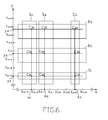
Fig. 6 is a schematic view of a five-point touch in which five points on the touch panel are touched. -
Fig. 7 is a plot of voltages measured at measuring points of the first conductive film of the touch panel in response to the five-point touch according to the first exemplary embodiment of a multi-touch detecting method of the present disclosure. -
Fig. 8 is a plot of voltages measured at measuring points of the first conductive film of the touch panel in response to the five-point touch according to the second exemplary embodiment of a multi-touch detecting method of the present disclosure. -
Figs. 9 to 11 are schematic views to demonstrate that the exemplary embodiments of the multi-touch detecting method of the present disclosure are capable of supporting different multi-touch functions implemented in the touch panel. - Reference will now be made to the drawings to describe various embodiments in detail.
- The exemplary embodiment of the multi-touch detecting method of the present disclosure is adapted for detecting touched points, such as points touched by a user, on a touch panel 100, and includes: applying a first voltage to the sides of a first conductive film 113 through first and second electrodes 115, 114, respectively; applying a second voltage greater than the first voltage to the sides of a second conductive film 123 through third and fourth electrodes 126, 124, respectively; measuring sequentially voltages at the different measuring points of the first conductive film 113 through the second electrodes 114; obtaining a first local maximum voltage, a second local maximum voltage and a local minimum voltage from the voltages measured at the different measuring points of the first conductive film 113, the measuring point corresponding to the local minimum voltage being located between the measuring point corresponding to the first local maximum voltage and the measuring point corresponding to the second local maximum voltage; determining a first location of the touched points in the second direction (X) based on a location of the measuring point corresponding to the first local maximum voltage in the second direction (X); determining a second location of the touched points in the second direction (X) based on a location of the measuring point corresponding to the second local maximum voltage in the second direction (X); measuring sequentially voltages at the different measuring points of the second conductive film 123 through the fourth electrodes 124; obtaining a first local minimum voltage, a second local minimum voltage and a local maximum voltage from the voltages measured at the different measuring points of the second conductive film 123, the measuring point corresponding to the local maximum voltage being located between the measuring point corresponding to the first local minimum voltage and the measuring point corresponding to the second local minimum voltage; determining a first location of the touched points in the first direction (Y) based on a location of the measuring point corresponding to the first local minimum voltage in the first direction (Y); and determining a second location of the touched points in the first direction (Y) based on a location of the measuring point corresponding to the second local minimum voltage in the first direction (Y). It is noted that the exemplary embodiment is a non-limiting example and the multi-touch detecting method of the exemplary embodiment can be extended to a detection of more than two touched points.
- The
first layer 110 includes afirst substrate 111, a firstconductive film 113, anadhesive film 112, afirst electrode 115, a plurality ofsecond electrodes 114, and a plurality ofconductive lines 116. The firstconductive film 113 is disposed on thefirst substrate 111, and is bonded to thefirst substrate 111 through theadhesive film 112. The firstconductive film 113 exhibits electric anisotropy, has a lower resistivity in a first direction (Y) than that in a second direction (X), i.e., Y-axis of a Cartesian plane, and further has two sides (not labeled) opposite to each other in the first direction (Y). Thefirst electrode 115 is disposed at one of the sides of the firstconductive film 113, and is coupled electrically to the aforesaid one of the sides of the firstconductive film 113. Thesecond electrodes 114, such as sensing electrodes, are uniformly disposed along the other side of the firstconductive film 113, and are coupled electrically to different first measuring points of the other side of the firstconductive film 113 distributed along the second direction (X), i.e., X-axis of the Cartesian plane, transverse to the first direction (Y). Theconductive lines 116 extend respectively from the first andsecond electrodes first layer 110 at which therecess 131 of theadhesive film 130 is formed. It is noted that the number of thesecond electrodes 114 employed in the exemplary embodiment shown inFig. 1 is illustrative only and can be adjusted according to actual requirements. - The
second layer 120 includes asecond substrate 121, a secondconductive film 123, anadhesive film 122, athird electrode 126, a plurality offourth electrodes 124, and a plurality ofconductive lines 125. The secondconductive film 123 is disposed on thesecond substrate 121, is bonded to thesecond substrate 121 through theadhesive film 122, and is juxtaposed with the firstconductive film 113 in a face-to-face manner. The secondconductive film 123 exhibits electric anisotropy, has a lower resistivity in the second direction (X) than that in the first direction (Y), and further has two sides (not labeled) opposite to each other in the second direction (X). Thethird electrode 126 is disposed at one of the sides of the secondconductive film 123, and is coupled electrically to the aforesaid one of the sides of the secondconductive film 123. Thefourth electrodes 124, such as sensing electrodes, are uniformly disposed along the other side of the secondconductive film 123, and are coupled electrically to different second measuring points of the other side of the secondconductive film 123 distributed along the first direction (Y). Theconductive lines 125 extend respectively from the third andfourth electrodes second layer 120 at which therecess 131 of theadhesive film 130 is formed. It is noted that the number of thefourth electrodes 124 employed in the exemplary embodiment shown inFig. 1 is illustrative only and can be adjusted according to actual requirements. - The
flexible print circuit 140 is provided with a plurality ofmetal pads 141 coupled electrically to theconductive lines conductive lines fourth electrodes - Each of the first and
second substrates adhesive films - In this embodiment, each of the first and second
conductive films 200920689 conductive film 113 can be made from a nanomaterial that has strings of interconnected carbon nanounits with each string substantially extending in the first direction (Y). The structure of the firstconductive film 113 permits the firstconductive film 113 to have the lower resistivity in the first direction (Y) and a higher resistivity in the second direction (X) which is about 50 to 350 times greater than the lower resistivity in the first direction (Y). In other words, the firstconductive film 113 has an electric anisotropy ratio ranging from about 50 to 350. The secondconductive film 123 can be made from a nanomaterial that has strings of interconnected carbon nanounits with each string substantially extending in the second direction (X). The structure of the secondconductive film 123 permits the secondconductive film 123 to have the lower resistivity in the second direction (X) and a higher resistivity in the first direction (Y) which is about 50 to 350 times greater than the lower resistivity in the second direction (X). In other words, the secondconductive film 123 has an electric anisotropy ratio ranging from about 50 to 350. Each of the first and secondconductive films conductive films - The first exemplary embodiment of a multi-touch detecting method of the present disclosure is adapted for detecting locations of touched points, such as the points touched by a user, on the
touch panel 100, and includes the following steps. The first measuring points of the firstconductive film 113 are scanned through thesecond electrodes 114, and x-components of the touched points are determined based on the response of the first measuring points. The second measuring points of the secondconductive film 123 are scanned through thefourth electrodes 124, and y-components of the touched points, are determined based on the response of the second measuring points. A first voltage is applied to the sides of the firstconductive film 113 through the first andsecond electrodes fourth electrode 124. Voltages at the first measuring points with the locations on the X-axis adjacent to or overlapping the x-components are measured sequentially through the correspondingsecond electrodes 114, in response to the application of the second voltage. The aforesaid one of the y-components and one of the x-components corresponding to one of the first measuring points at which a local extreme voltage is measured are outputted, as the location of a corresponding one of the touched points. - In this embodiment, the step of scanning the first measuring points and determining x-components includes the sub-steps of: applying the first voltage to the sides of the first
conductive film 113 through the first andsecond electrodes conductive film 123 through the third andfourth electrodes second electrodes 114 in response to the application of the second voltage to the sides of the secondconductive film 123; obtaining local maximal voltages and local minimal voltage(s) among the local maximal voltages from the voltages measured at the first measuring points; and determining the x-components based on the locations of the first measuring points corresponding to the local maximal voltages on the X-axis, respectively. In addition, the step of scanning the second measuring points and determining y-components includes the following sub-steps. Measuring sequentially voltages at the second measuring points through thefourth electrodes 124 in response to the application of the first voltage to the sides of the firstconductive film 113; obtaining local minimal voltages and local maximal voltage(s) among the local maximal voltages from the voltages measured at the second measuring points; and determining the y-components based on the locations of the second measuring points corresponding to the local minimal voltages on the Y-axis, respectively. - Preferably, in the measuring sub-steps, the voltages are measured in such a manner that while each of measuring points is measured, the first voltage is applied to the rest of the first measuring points and the second voltage is applied to the rest of the second measuring points, in order to eliminate an adverse effect on the measuring point being measured caused by the rest of the measuring points and to improve the accuracy of the measured voltage at the measuring point being measured.
- When the
touch panel 100 is not touched, the first and secondconductive films second electrodes 114 are all equal to the first voltage, whereas the voltages measured at thefourth electrodes 124 are all equal to the second voltage. As an example, when two points on thetouch panel 100 are touched, the first and secondconductive films second electrodes 114 corresponding to the touched points rise above the first voltage (seeFigs. 2 and3 ), whereas the voltages at the correspondingfourth electrodes 124 corresponding to the touched points drop below the second voltage (seeFigs. 4 and5 ). - When the two touched points are not close to each other, the response of the voltages at the corresponding
second electrodes 114 and the correspondingfourth electrodes 124 corresponding to the two selected points on thetouch panel 100 follows a pattern different from that of the voltages at the correspondingsecond electrodes 114 and the correspondingfourth electrodes 124 when the two touched points are close to each other. Hence, determination of the x-components or the y-components will be based on one set of equations when the touched points are distant from each other or on a different set of equations when the touched points are close to each other, and will be described in detail as follows. - Referring to
Fig. 2 , in combination withFig. 1 , assume, in response to the two touched points on thetouch panel 100, that a first local maximal voltage Vn is measured at the nth one of the first measuring points, that a second local maximal voltage Vm is measured at the mth one of the first measuring points, and that n≥2, and m≥n+3, which represents that the touched points are distant from each other on the X-axis. A first x-component Xa corresponding to the location of a first one of the touched points is determined by one of the following equations according to a respective one of the following conditions:

and
where Vn-1 is the voltage measured at the n-1th one of the first measuring points, Vn+1 is the voltage measured at the n+1th one of the first measuring points, Xn is the location of the nth one of the first measuring points on the X-axis, and Px is a distance between two adjacent ones ofthe first measuring points. - In addition, a second x-component Xb corresponding to the location of a second one of the touched points is determined by one of the following equations according to a respective one of the following conditions:


and
where Vm-1 is the voltage measured at the m-1th one of the first measuring points, Vm+1 is the voltage measured at the m+1th one of the first measuring points, and Xm is the location of the mth one of the first measuring points on the X-axis. - Referring to
Fig. 3 , in combination withFig. 1 , assume, in response to the two touched points on thetouch panel 100, that is m=n+2, which represents that the touched points are close to each other on the X-axis, and that a local minimal voltage Vn+1 (=Vm-1) is measured at the n+1th, i.e., m-1th, one of the first measuring points, and can be separated into Vn+1' and Vm-1" as functions of (Va, Yn-1. Vn, Vn+1, Vm, Vm+1) defined below. A first x-component Xa and a second x-component Xb corresponding respectively to the locations of the two touched points are determined by the following equations according to respective ones of the following conditions, respectively:


and
where Va is the first voltage. - Similarly, referring to
Fig. 4 , in combination withFig. 1 , assume, in response to the two touched points on thetouch panel 100, that a first local minimal voltage VS is measured at the sth one of the second measuring points, that a second local minimal voltage Vt is measured at the tth one of the second measuring points, and that s≥2, and t≥s+3, which represents that the touched points are distant from each other on the Y-axis. A first y-component Ya corresponding to the location of the first one of the touched points is determined by one of the following equations according to a respective one of the following conditions:

and
where Vs-1 is the voltage measured at the s-1th one of the second measuring points, Vs+1 is the voltage measured at the s+1th one of the second measuring points, Ys is the location of the sth one of the second measuring points on the Y-axis, and Py is a distance between two adjacent ones ofthe second measuring points. - In addition, a second y-component Yb corresponding to the location of the second one of the touched points is determined by one of the following equations according to a respective one of the following conditions:


and
where Vt-1 is the voltage measured at the t-1th one of the second measuring points, Vt+1 is the voltage measured at the t+1th one of the second measuring points, and Yt is the location of the tth one of the second measuring points on the Y-axis. - Referring to
Fig. 5 , in combination withFig. 1 , assume, in response to the two touched points on thetouch panel 100, that t=s+2, which represents that the touched points are close to each other on the Y-axis, and that a local maximal voltage Vs+1 (=Vt-1) is measured at the s+1th, i.e., t-1th, one of the second measuring points, and can be separated into Vs+1' and Vt-1" as functions of (Vb, Vs-1, Vs, Vs+1, Vt, Vt+1) defined below. A first y-component Ya and a second y-component Yb corresponding respectively to the locations of the touched points are determined by the following equations according to respective ones of the following conditions, respectively:


and
where Vb is the second voltage. - Although the x-components and the y-components corresponding to the locations of the touched points are determined, the exact pairs of the x-components and the y-components corresponding to the locations of the touched points are yet to be determined. The following describes how the exact pairs of the x-components and the y-components are determined. Referring to
Fig. 6 , in combination withFig. 1 , assume the following conditions. Five touched points (C11, C21, C23, C31, C32) on thetouch panel 100 are touched. The touched points (C11, C21, C31) are aligned in the first direction (Y). The touched points (C21, C23) are aligned in the second direction (X). The touched points (C31, C32) are aligned in the second direction (X). There are eight first measuring points with the locations on the X-axis of Xm-3 ∼ Xm+4, respectively. There are eight second measuring points with the locations on the Y-axis of Yn-3 ∼ Yn+4, respectively; that the x-components are determined to be x1, x2, and x3. The y-components are determined to be y1, y2, and y3. The x-components x1, x2, x3 and the y-components y1, y2, y3 can be paired into nine locations including the locations of the touched points (C11, C21, C23, C31, C32) and the locations of false points (C12, C13, C22, C33). The following describes how the false points (C12, C13, C22, C33) are determined based on the voltages measured at the first measuring points in response to the application of the second voltage. - According to the obtained x-components x1, x2, x3 and the y-components y1, y2, y3, three first regions (S1, S2, S3) on the first
conductive film 113 corresponding respectively to the x-components x1, x2, x3 can be found, and three second regions (D1, D2, D3) on the secondconductive film 123 corresponding respectively to the y-components y1, y2, y3 can be found. The first one of the first regions (S1) corresponds to two of the first measuring points with the locations on the X-axis, i.e., Xm-3 and Xm-2, adjacent to a first one of the x-components x1. The second one of the first regions (S2) corresponds to two of the first measuring points with the locations on the X-axis, i.e., Xm-1 and Xm, adjacent to a second one of the x-components x2. The third one of the first regions (S3) corresponds to one of the first measuring points with the location on the X-axis, i.e., Xm+3, overlapping a third one of the x-components x3. The first one of the second regions (D1) corresponds to one of the second measuring points with the location on the Y-axis, i.e., Yn-3, overlapping a first one of the y-components y1. The second one of the second regions (D2) corresponds to two of the second measuring points with the locations on the Y-axis, i.e., Yn-1 and Yn, adjacent to a second one of the y-components y2. The third one of the second regions (D3) corresponds to two of the second measuring points with the locations on the Y-axis, i.e., Yn+2 and Yn+3, adjacent to a third one of the y-components y3. - After the application of the first voltage to the sides of the first
conductive film 113 through the first andsecond electrodes fourth electrode 124. The voltages measured at the first measuring points with locations Xm-3, Xm-2, Xm-1, Xm, and Xm+3 on the X-axis through the correspondingsecond electrodes 114 in response to the application of the second voltage are shown inFig. 7(A) . A local extreme voltage is measured at the first measuring point with the location Xm-2 on the X-axis, which means there is a touched point (C11) located at the intersection of the regions (S1, D1), and there are two false points (C12, C13) located at the intersection of the regions (S2, D1) and the intersection of the regions (S3, D1), respectively. Hence, the location of the touched point (C11) is determined to be (x1, y1). It is noted that, because the second voltage is greater than the first voltage in this embodiment, the local extreme voltage is a local maximal voltage. Alternatively, the second voltage can be smaller than the first voltage. As such, the local extreme voltage thus measured will be a local minimal voltage. - Next, the second voltage is applied to the second measuring points with the locations Yn-1 and Yn on the Y-axis, which correspond to the second one of the second regions (D2), through the corresponding
fourth electrodes 124. The voltages measured at the first measuring points with locations Xm-3, Xm-2, Xm-1, Xm, and Xm+3 on the X-axis through the correspondingsecond electrodes 114 in response to the application of the second voltage are shown inFig. 7(B) . Two local extreme voltages are measured at the first measuring points with the locations Xm-2 and Xm+3 on the X-axis, respectively, which means there are two touched points (C21, C23) located at the intersection of the regions (S1, D2) and the intersection of the regions (S3, D2), respectively, and there is a false point (C22) located at the intersection of the regions (S2, D2). Hence, the locations of the touched points (C21, C23) are determined to be (x1, y2) and (x3, y2), respectively. - Finally, the second voltage is applied to the second measuring points with the locations Yn+2 and Yn+3 on the Y-axis of, which correspond to the third one of the second regions (D3), through the corresponding
fourth electrodes 124. The voltages measured at the first measuring points with locations Xm-3, Xm-2, Xm-1, Xm, and Xm+3 on the X-axis through the correspondingsecond electrodes 114 in response to the application of the second voltage are shown inFig. 7(C) . Two local extreme voltages are measured at the first measuring points with the locations Xm-2 and Xm on the X-axis, respectively, which means there are two touched points (C31, C32) located at the intersection of the regions of (S1, D3) and the intersection of the regions (S2, D3), respectively, and there is a false point (C32) located at the intersection of the regions (S3, D3). Hence, the locations of the touched points (C31, C32) are determined to be (x1, y3) and (x2, y3), respectively. - Preferably, in the step of measuring voltages at the first measuring points in response to the application of the second voltage, the voltages are measured in such a manner that while each of the first measuring points is measured, the first voltage is applied to the rest of the first measuring points and to the second measuring points with the locations on the Y-axis adjacent to or overlapping the rest of the y-components. In this embodiment, the multi-touch detecting method further includes: providing the first or second voltage to at least one of the second measuring points located between two of the second measuring points with the locations on the Y-axis adjacent to or overlapping two adjacent ones of the y-components, respectively.
- The second exemplary embodiment of a multi-touch detecting method of the present disclosure is adapted for detecting locations of touched points on the
touch panel 100, and includes the following steps. There is the step of scanning the first measuring points and determining x-components of the first embodiment. There is the step of scanning the second measuring points and determining y-components of the first embodiment. There is the step of applying the first voltage of the first embodiment. The step (d) is the step of applying the second voltage to the second measuring point(s) corresponding to at least one of the second regions (D1, D2, D3) through the correspondingfourth electrode 124, and measuring sequentially voltages at the first measuring points with the locations on the X-axis adjacent to or overlapping the x-components through the correspondingsecond electrodes 114, in response to the application of the second voltage. The step (e) after step (d) is step of simultaneously applying the second voltage to the second measuring point(s) corresponding to the aforesaid at least one of the second regions (D1, D2, D3) in step (d), and to at least one of the second measuring points corresponding to another one of the second regions (D1, D2, D3) through the correspondingfourth electrode 124, and measuring sequentially voltages at the first measuring points with the locations on the X-axis adjacent to or overlapping the x-components through the correspondingsecond electrodes 114, in response to the application of the second voltage. The step (f) is the step of outputting the aforesaid one of the y-components and one of the x-components, which corresponds to one of the first measuring points at which a local extreme voltage is measured in step (e), as the location of a corresponding one of the touched points when the voltages measured at the aforesaid one of the first measuring points in steps (e) and (d) are different. The locations of the rest of the touched points are determined in a similar manner as steps (d) to (f). - In more detail, referring to
Fig. 6 , in combination withFig. 1 , after the application of the first voltage to the sides of the firstconductive film 113 through the first andsecond electrodes fourth electrode 124 in step (d). The voltages measured at the first measuring points with locations Xm-3, Xm-2, Xm-1, Xm, and Xm+3 on the X-axis through the correspondingsecond electrodes 114 in response to the application of the second voltage are shown inFig. 8(A) . A local extreme voltage is measured at the first measuring point with the location Xm-2 on the X-axis, which means there is a touched points (C11) located at the intersection of the regions (S1, D1), and there are two false points (C12, C13) located at the intersection of the regions (S2, D1) and the intersection of the regions (S3, D1), respectively. Hence, the location of the touched point (C11) is determined to be (x1, y1). - Next, the second voltage is simultaneously applied to the second measuring point with the location Yn-3 on the Y-axis and to the second measuring points with the locations Yn-1 and Yn on the Y-axis, which correspond to the second one of the second regions (D2), through the corresponding
fourth electrodes 124 in step (e), i.e., the second regions (D1, D2) are applied with the second voltage at the same time. The voltages measured at the first measuring points with locations Xm-3, Xm-2, Xm-1, Xm, and Xm+3 on the X-axis through the correspondingsecond electrodes 114 in response to the application of the second voltage are shown inFig. 8(B) . Two local extreme voltages are measured at the first measuring points with the locations Xm-2 and Xm+3 on the X-axis, respectively. The voltages measured at the first measuring point with the location Xm-2 on the X-axis in step (e) (seeFig. 8(B) ) and step (d) (seeFig. 8(A) ) are different, and the voltages measured at the first measuring point with the location Xm+3 on the X-axis in step (e) (seeFig. 8(B) ) and step (d) (seeFig. 8(A) ) are different, which means there are two touched points (C21, C23) located at the intersection of the regions (S1, D2) and the intersection of the regions (S3, D2), respectively, and there is a false point (C22) located at the intersection of the regions (S2, D2). Hence, the locations of the touched points (C21, C23) are determined to be (x1, y2) and (x3, y2), respectively. - Finally, the second voltage is simultaneously applied to the second measuring point with the location Yn-3 on the Y-axis, to the second measuring points with the locations Yn-1 and Yn on the Y-axis, and to the second measuring points with the locations Yn+2 and Yn+3 on the Y-axis, which correspond to the third one of the second regions (D3), through the corresponding
fourth electrodes 124 in step (e), i.e., all the second regions (D1, D2, D3) are applied with the second voltage at the same time. The voltages measured at the first measuring points with locations Xm-3, Xm-2, Xm-1, Xm, and Xm+3 on the X-axis through the correspondingsecond electrodes 114 in response to the application of the second voltage are shown inFig. 8(C) . Three local extreme voltages are measured at the first measuring points with the locations Xm-2, Xm and Xm+3 on the X-axis. The voltages measured at the first measuring point with the location Xm-2 on the X-axis in step (e) (seeFig. 8(C) ) and step (d) (seeFig. 8(B) ) are different, the voltages measured at the first measuring point with the location Xm on the X-axis in step (e) (seeFig. 8(C) ) and step (d) (seeFig. 8(B) ) are different, and the voltages measured at the first measuring point with the location Xm+3 on the X-axis in step (e) (seeFig. 8(C) ) and step (d) (seeFig. 8(B) ) are substantially the same, which means there are two touched points (C31, C32) located at the intersection of the regions (S1, D3) and the intersection of the regions (S2, D3), respectively, and there is a false point (C33) located at the intersection of the regions (S3, D3). Hence, the locations of the touched points (C31, C32) are determined to be (x1, y3) and (x2, y3), respectively. - Preferably, in steps (d) and (e), the voltages are measured in such a manner that while each of the first measuring points is measured, the first voltage is applied to the rest of the first measuring points and to the second measuring points with the locations on the Y-axis adjacent to or overlapping the rest of the y-components. In this embodiment, the multi-touch detecting method further includes: (g) providing the first or second voltage to at least one of the second measuring points located between two of the second measuring points with the locations on the Y-axis adjacent to or overlapping two adjacent ones of the y-components, respectively.
- As described above, the locations of the touched points can be thus determined. Exemplary functions provided by the embodiments of the multi-touch detecting method are described below.
-
Fig. 9 shows "zoom-in" and "zoom-out" functions provided by the embodiments of the multi-touch detecting method with two two-point touches on thetouch panel 100 executed sequentially at a scanning interval. In the first two-point touch, the locations of the touched points (A, B) on the touch panel are determined to be (x1, y1) and (x2, y2), respectively, with a first distance therebetween. In the second two-point touch, the locations of the touched points (A', B') on the touch panel are determined to be (x1', y1') and (x2', y2'), respectively, with a second distance therebetween greater than the first distance. As such, the "zoom-in" function can be triggered by first executing the first two-point touch and then the second two-point touch, and the "zoom-out" function can be triggered by first executing the second two-point touch and then the second two-point touch. -
Fig. 10 shows a "translation" function provided by the embodiments of the multi-touch detecting method with two two-point touches on the touch panel executed sequentially at a scanning interval. In the first two-point touch, the locations of the touched points (A, B) on the touch panel are determined to be (x1, y1) and (x2, y2), respectively. In the second two-point touch, the locations of the touched points (A', B') on thetouch panel 100 are determined to be (x1', y1') and (x2', y2'), respectively, with the movement from A to A' being substantially the same as the movement from B to B'. As such, the "translation" function can be triggered by executing the first and second two-point touches sequentially. -
Fig. 11 shows a "rotation" function provided by the embodiment of the multi-touch detecting method with two two-point touches on the touch panel executed sequentially at a scanning interval. In the first two-point touch, the locations of the touched points (A, B) on the touch panel are determined to be (x1, y1) and (x2, y2), respectively. In the second two-point touch, the locations of the touched points (A', B') on thetouch panel 100 are determined to be (x1', y1') and (x2', y2'), respectively, with the rotation from A to A' and the rotation from B to B' being in the same direction, i.e., a clockwise direction or a counterclockwise direction. As such, the "rotation" function can be triggered by executing the first and second two-point touches sequentially. - In summary, with the use of the first and second
conductive films touch panel 100 is simple and the multi-touch detecting method implemented by thetouch panel 100 is simple. - The steps of all the methods described above will be performed by signal processing circuitery included in a touch screen device incorporating the panel, or by separate circuitry. Circuitry in this context includes analogue and digital circuitry. Digital circuitry may be special purpose hardware and/or may include programmable DSP or microprocessor circuitry, provided with suitable program instructions.
- It is to be understood that even though numerous characteristics and advantages of the present embodiments have been set forth in the foregoing description, together with details of the structures and functions of the embodiments, the disclosure is illustrative only; and that changes may be made in detail, especially in matters of shape, size, and arrangement of parts, within the principles of the embodiments, to the full extent indicated by the broad general meaning of the terms in which the appended claims are expressed. Moreover the claims may be expanded to claim the touch device including means for implementing the respective steps of the methods presently claimed.
Claims (23)
- A touch panel, comprising:a first substrate;a second substrate;a first conductive film disposed on the first substrate; anda second conductive film disposed on the second substrate and juxtaposed with the first conductive film in a face-to-face manner;wherein the first conductive film exhibits electric anisotropy and has a lower resistivity in a first direction than that in a second direction transverse to the first direction; and the second conductive film exhibits electric anisotropy and has a lower resistivity in the second direction than that in the first direction.
- The touch panel of claim 1, wherein each of the first and second conductive films has an electric anisotropy ratio ranging from about 100 to 200.
- The touch panel of claim 1, wherein each of the first and second conductive films has a surface resistivity ranging from about 1 kilohms per square to 800 kilohms per square.
- The touch panel of claim 1, wherein the first conductive film is made from a nanomaterial that has strings of carbon nanounits with each string substantially extending in the first direction, the second conductive film being made from a nanomaterial that has strings of carbon nanouits with each string substantially extending in the second direction.
- The touch panel of claim 1, wherein the first conductive film has two sides opposite to each other in the first direction, the touch panel further comprising a plurality of electrodes uniformly disposed along one of the sides of the first conductive film and coupled electrically to the one of the sides of the first conductive film.
- The touch panel of claim 1, wherein the second conductive film has two sides opposite to each other in the second direction, the touch panel further comprising a plurality of electrodes uniformly disposed along one of the sides of the second conductive film and coupled electrically to the one of the sides of the second conductive film.
- The touch panel of claim 1, further comprising: an adhesive film extending along sides of the first and second conductive films and bonding the first and second conductive films together.
- The touch panel of claim 1, further comprising a plurality of spacers disposed between the first and second conductive films.
- A multi-touch detecting method adapted for detecting locations of touched points on a touch panel, the touch panel including first and second conductive films insulated from each other and coupled electrically to each other through touch, the multi-touch detecting method comprising:scanning first measuring points of the first conductive film distributed along X-axis of a Cartesian plane of the touch panel, and determining x-components of the touched points, based on the response of the first measuring points;scanning second measuring points of the second conductive film distributed along Y-axis of the Cartesian plane of the touch panel, and determining y-components of the touched points, based on the response of the second measuring points;applying a first voltage to the first conductive film; andapplying a second voltage different from the first voltage to at least one of the second measuring points with the location on the Y-axis adjacent to or overlapping one of the y-components, measuring sequentially voltages at the first measuring points with the locations on the X-axis adjacent to or overlapping the x-components, in response to the application of the second voltage, and outputting the one of the y-components and one of the x-components, which corresponds to one of the first measuring points at which a local extreme voltage is measured, as the location of a corresponding one of the touched points.
- The multi-touch detecting method of claim 9, wherein the voltages are measured in such a manner that while each of the first measuring points is measured, the first voltage is applied to the rest of the first measuring points.
- The multi-touch detecting method of claim 9, further comprising providing the first voltage to at least one of the second measuring points located between two of the second measuring points with the locations on the Y-axis adjacent to or overlapping two adjacent ones ofthe y-components, respectively.
- The multi-touch detecting method of claim 9, wherein the second voltage is greater than the first voltage, the local extreme voltage being a local maximal voltage.
- The multi-touch detecting method of claim 9, wherein the second voltage is smaller than the first voltage, the local extreme voltage being a local minimal voltage.
- A multi-touch detecting method adapted for detecting locations of touched points on a touch panel, the touch panel including first and second conductive films insulated from each other and coupled electrically to each other through touch, the multi-touch detecting method comprising:(a) scanning first measuring points of the first conductive film distributed along X-axis of a Cartesian plane of the touch panel, and determining x-components, which correspond to the locations of the touched points, based on the response of the first measuring points;(b) scanning second measuring points of the second conductive film distributed along Y-axis of the Cartesian plane of the touch panel, and determining y-components, which correspond to the locations of the touched points, based on the response of the second measuring points;(c) applying a first voltage to the first conductive film;(d) applying a second voltage different from the first voltage to at least one of the second measuring points with the location on the Y-axis adjacent to or overlapping one of the y-components, and measuring sequentially voltages at the first measuring points with the locations on the X-axis adjacent to or overlapping the x-components, in response to the application of the second voltage;(e) simultaneously applying the second voltage to the at least one of the second measuring points with the location on the Y-axis adjacent to or overlapping the one of the y-components in step (d), and to at least one of the second measuring points with the location on the Y-axis adjacent to or overlapping another one of the y-components, and measuring sequentially voltages at the first measuring points with the locations on the X-axis adjacent to or overlapping the x-components, in response to the application of the second voltage; and(f) outputting the one of the y-components and one of the x-components, which corresponds to one of the first measuring points at which a local extreme voltage is measured in step (e), as the location of a corresponding one of the touched points when the voltages measured at the one of the first measuring points in steps (d) and (e) are different.
- The multi-touch detecting method of claim 14, wherein in steps (d) and (e), the voltages are measured in such a manner that while each of the first measuring points is measured, the first voltage is applied to the rest of the first measuring points.
- The multi-touch detecting method of claim 14, further comprising: providing the first voltage to at least one of the second measuring points located between two of the second measuring points with the locations on the Y-axis adjacent to or overlapping two adjacent ones ofthe y-components, respectively.
- The multi-touch detecting method of claim 14, wherein the second voltage is greater than the first voltage, in step (f), the local extreme voltage being a local maximal voltage.
- The multi-touch detecting method of claim 14, wherein the second voltage is smaller than the first voltage, in step (f), the local extreme voltage being a local minimal voltage.
- A multi-touch detecting method adapted for detecting locations of touched points on a touch panel, the touch panel including first and second conductive films insulated from each other, the first conductive film having a plurality of first measuring points distributed along X-axis of a Cartesian plane of the touch panel, the second conductive film having a plurality of second measuring points distributed along Y-axis of the Cartesian plane of the touch panel, the multi-touch detecting method comprising:applying a first voltage to the first conductive film;applying a second voltage different from the first voltage to one of the second measuring points;measuring sequentially voltages at the first measuring points in response to the application of the second voltage; andoutputting a location based on the one of the second measuring points and one of the first measuring points at which a local extreme voltage is measured.
- The multi-touch detecting method of claim 19, wherein the voltages are measured in such a manner that while each of the first measuring points is measured, the first voltage is applied to the rest of the first measuring points.
- The multi-touch detecting method of claim 19, wherein the second voltage is greater than the first voltage, the local extreme voltage being a local maximal voltage.
- The multi-touch detecting method of claim 19, wherein the second voltage is smaller than the first voltage, the local extreme voltage being a local minimal voltage.
- A multi-touch detecting method adapted for detecting locations of touched points on a touch panel, the touch panel including first and second conductive films insulated from each other the first conductive film having a plurality of first measuring points distributed along X-axis of a Cartesian plane, the second conductive film having a plurality of second measuring points distributed along Y-axis of the Cartesian plane, the multi-touch detecting method comprising:(a) applying a first voltage to the first conductive film;(b) applying a second voltage different from the first voltage to one of the second measuring points, and measuring sequentially voltages at the first measuring points in response to the application of the second voltage;(c) simultaneously applying the second voltage to the one of the second measuring points in step (b) and to another one of the second measuring points, and measuring sequentially voltages at the first measuring points in response to the application of the second voltage; and(d) outputting a location based on the another one of the second measuring points and one of the first measuring points at which a local extreme voltage is measured in step (c) when the voltages measured at the one of the first measuring points in steps (b) and (c) are different.
Applications Claiming Priority (1)
| Application Number | Priority Date | Filing Date | Title |
|---|---|---|---|
| CN2009103042467A CN101950213B (en) | 2009-07-10 | 2009-07-10 | Touch screen and multi-point identification method used for same |
Publications (3)
| Publication Number | Publication Date |
|---|---|
| EP2275911A2 true EP2275911A2 (en) | 2011-01-19 |
| EP2275911A3 EP2275911A3 (en) | 2011-06-08 |
| EP2275911B1 EP2275911B1 (en) | 2016-12-14 |
Family
ID=42857989
Family Applications (1)
| Application Number | Title | Priority Date | Filing Date |
|---|---|---|---|
| EP10168941.2A Active EP2275911B1 (en) | 2009-07-10 | 2010-07-08 | Touch panel and multi-touch detecting method thereof |
Country Status (5)
| Country | Link |
|---|---|
| US (1) | US8400421B2 (en) |
| EP (1) | EP2275911B1 (en) |
| JP (1) | JP5634778B2 (en) |
| KR (1) | KR20110005650A (en) |
| CN (1) | CN101950213B (en) |
Cited By (1)
| Publication number | Priority date | Publication date | Assignee | Title |
|---|---|---|---|---|
| EP2273356A3 (en) * | 2009-07-10 | 2012-11-07 | Chimei InnoLux Corporation | Multi-touch detecting method for detecting locations of touched points on a touch panel |
Families Citing this family (3)
| Publication number | Priority date | Publication date | Assignee | Title |
|---|---|---|---|---|
| US8536748B2 (en) | 2008-11-11 | 2013-09-17 | Ford Global Technologies, Llc | Permanent magnet machine with different pole arc angles |
| JP5606242B2 (en) | 2010-09-24 | 2014-10-15 | 株式会社ジャパンディスプレイ | Display device |
| TW201310470A (en) * | 2011-08-31 | 2013-03-01 | Shih Hua Technology Ltd | Transparent conductive film and touch panel using the same |
Citations (3)
| Publication number | Priority date | Publication date | Assignee | Title |
|---|---|---|---|---|
| US20060097991A1 (en) | 2004-05-06 | 2006-05-11 | Apple Computer, Inc. | Multipoint touchscreen |
| US20080158181A1 (en) | 2007-01-03 | 2008-07-03 | Apple Computer, Inc. | Double-sided touch sensitive panel and flex circuit bonding |
| TW200920689A (en) | 2007-11-09 | 2009-05-16 | Hon Hai Prec Ind Co Ltd | Apparatus and method for synthesizing films of carbon nanotubes |
Family Cites Families (17)
| Publication number | Priority date | Publication date | Assignee | Title |
|---|---|---|---|---|
| US5825352A (en) * | 1996-01-04 | 1998-10-20 | Logitech, Inc. | Multiple fingers contact sensing method for emulating mouse buttons and mouse operations on a touch sensor pad |
| US5818430A (en) * | 1997-01-24 | 1998-10-06 | C.A.M. Graphics Co., Inc. | Touch screen |
| JP2002042582A (en) * | 2000-07-25 | 2002-02-08 | Nippon Sheet Glass Co Ltd | Manufacturing method of substrate with transparent conductive film, and the substrate manufactured by the method, and touch panel using the substrate |
| US6762752B2 (en) * | 2001-11-29 | 2004-07-13 | N-Trig Ltd. | Dual function input device and method |
| WO2004106404A1 (en) * | 2003-05-27 | 2004-12-09 | Fujitsu Limited | Organic conductive polymer composition, transparent conductive film and transparent conductor both comprising the composition, and input device comprising the transparent conductor and its manufacturing method |
| WO2005017732A1 (en) * | 2003-08-18 | 2005-02-24 | Gunze Limited | Transparent touch panel and electronic apparatus |
| GB0319714D0 (en) * | 2003-08-21 | 2003-09-24 | Philipp Harald | Anisotropic touch screen element |
| US20050209392A1 (en) * | 2003-12-17 | 2005-09-22 | Jiazhong Luo | Polymer binders for flexible and transparent conductive coatings containing carbon nanotubes |
| US8355009B2 (en) * | 2007-04-25 | 2013-01-15 | Mcdermid William J | Method and apparatus for determining coordinates of simultaneous touches on a touch sensor pad |
| JP5212377B2 (en) * | 2007-11-07 | 2013-06-19 | コニカミノルタホールディングス株式会社 | Transparent electrode and method for producing transparent electrode |
| CN101464764B (en) * | 2007-12-21 | 2012-07-18 | 清华大学 | Touch screen and display equipment |
| EP2073109A3 (en) | 2007-12-21 | 2012-08-22 | Tsing Hua University | Touch panel and display device using the same |
| CN101464766B (en) * | 2007-12-21 | 2011-11-30 | 清华大学 | Touch screen and display equipment |
| CN101464765B (en) * | 2007-12-21 | 2011-01-05 | 鸿富锦精密工业(深圳)有限公司 | Touch screen and display equipment |
| US20090174675A1 (en) * | 2008-01-09 | 2009-07-09 | Dave Gillespie | Locating multiple objects on a capacitive touch pad |
| US8749496B2 (en) * | 2008-12-05 | 2014-06-10 | Apple Inc. | Integrated touch panel for a TFT display |
| US8427444B2 (en) * | 2010-04-12 | 2013-04-23 | Silicon Integrated Systems Corp. | Ghost cancellation method for multi-touch sensitive device |
-
2009
- 2009-07-10 CN CN2009103042467A patent/CN101950213B/en active Active
-
2010
- 2010-06-29 US US12/825,347 patent/US8400421B2/en active Active
- 2010-07-08 KR KR1020100065771A patent/KR20110005650A/en not_active Application Discontinuation
- 2010-07-08 EP EP10168941.2A patent/EP2275911B1/en active Active
- 2010-07-09 JP JP2010156759A patent/JP5634778B2/en active Active
Patent Citations (3)
| Publication number | Priority date | Publication date | Assignee | Title |
|---|---|---|---|---|
| US20060097991A1 (en) | 2004-05-06 | 2006-05-11 | Apple Computer, Inc. | Multipoint touchscreen |
| US20080158181A1 (en) | 2007-01-03 | 2008-07-03 | Apple Computer, Inc. | Double-sided touch sensitive panel and flex circuit bonding |
| TW200920689A (en) | 2007-11-09 | 2009-05-16 | Hon Hai Prec Ind Co Ltd | Apparatus and method for synthesizing films of carbon nanotubes |
Cited By (1)
| Publication number | Priority date | Publication date | Assignee | Title |
|---|---|---|---|---|
| EP2273356A3 (en) * | 2009-07-10 | 2012-11-07 | Chimei InnoLux Corporation | Multi-touch detecting method for detecting locations of touched points on a touch panel |
Also Published As
| Publication number | Publication date |
|---|---|
| JP2011018339A (en) | 2011-01-27 |
| EP2275911A3 (en) | 2011-06-08 |
| JP5634778B2 (en) | 2014-12-03 |
| CN101950213A (en) | 2011-01-19 |
| US20110005844A1 (en) | 2011-01-13 |
| US8400421B2 (en) | 2013-03-19 |
| EP2275911B1 (en) | 2016-12-14 |
| CN101950213B (en) | 2013-05-22 |
| KR20110005650A (en) | 2011-01-18 |
Similar Documents
| Publication | Publication Date | Title |
|---|---|---|
| EP2273356B1 (en) | Multi-touch detecting method for detecting locations of touched points on a touch panel | |
| US9304630B2 (en) | Touch panel | |
| JP4175472B2 (en) | Liquid crystal display device with electromagnetic induction type touch panel | |
| KR101109382B1 (en) | touch panel | |
| US20150286332A1 (en) | Force imaging input device and system | |
| EP2275909A2 (en) | Touch panel and detecting method thereof | |
| US9329710B2 (en) | Touchscreen panel and touchscreen device | |
| US20110248934A1 (en) | Contactless touch panel | |
| US20110134073A1 (en) | Touch panel device of digital capacitive coupling type with high sensitivity | |
| US20100001975A1 (en) | Portable computer | |
| KR101501940B1 (en) | Touch screen and manufacturing method thereof | |
| KR101452053B1 (en) | Touchscreen device and screen zooming method thereof | |
| JP2011048827A (en) | Touch panel and method of locating touch point of the same | |
| US20090079708A1 (en) | Three-wire resistive touch panel and display device using same | |
| US20140043252A1 (en) | Touchscreen panel and touchscreen device | |
| US20140160057A1 (en) | Touch sensing method and touch sensing apparatus | |
| US20140340590A1 (en) | Touch panel | |
| EP2275911A2 (en) | Touch panel and multi-touch detecting method thereof | |
| TWI465992B (en) | Method for detecting touch spot of touch panel | |
| US9285914B2 (en) | Anisotropic touchscreen | |
| CN107239173B (en) | Touch device, touch display device and driving method thereof | |
| KR101184459B1 (en) | Pressure sensor | |
| KR101444533B1 (en) | Touch screen panel and touch screen apparatus | |
| CN206991274U (en) | Contactor control device, touch control display apparatus | |
| JPH11242561A (en) | Touch panel, display device with input function and electronic device |
Legal Events
| Date | Code | Title | Description |
|---|---|---|---|
| PUAI | Public reference made under article 153(3) epc to a published international application that has entered the european phase |
Free format text: ORIGINAL CODE: 0009012 |
|
| AK | Designated contracting states |
Kind code of ref document: A2 Designated state(s): AL AT BE BG CH CY CZ DE DK EE ES FI FR GB GR HR HU IE IS IT LI LT LU LV MC MK MT NL NO PL PT RO SE SI SK SM TR |
|
| AX | Request for extension of the european patent |
Extension state: BA ME RS |
|
| PUAL | Search report despatched |
Free format text: ORIGINAL CODE: 0009013 |
|
| AK | Designated contracting states |
Kind code of ref document: A3 Designated state(s): AL AT BE BG CH CY CZ DE DK EE ES FI FR GB GR HR HU IE IS IT LI LT LU LV MC MK MT NL NO PL PT RO SE SI SK SM TR |
|
| AX | Request for extension of the european patent |
Extension state: BA ME RS |
|
| 17P | Request for examination filed |
Effective date: 20111207 |
|
| 17Q | First examination report despatched |
Effective date: 20130612 |
|
| GRAP | Despatch of communication of intention to grant a patent |
Free format text: ORIGINAL CODE: EPIDOSNIGR1 |
|
| RIC1 | Information provided on ipc code assigned before grant |
Ipc: G06F 3/041 20060101ALI20160503BHEP Ipc: G06F 3/045 20060101AFI20160503BHEP Ipc: G06F 3/0488 20130101ALI20160503BHEP |
|
| INTG | Intention to grant announced |
Effective date: 20160602 |
|
| GRAS | Grant fee paid |
Free format text: ORIGINAL CODE: EPIDOSNIGR3 |
|
| STAA | Information on the status of an ep patent application or granted ep patent |
Free format text: STATUS: GRANT OF PATENT IS INTENDED |
|
| GRAA | (expected) grant |
Free format text: ORIGINAL CODE: 0009210 |
|
| STAA | Information on the status of an ep patent application or granted ep patent |
Free format text: STATUS: THE PATENT HAS BEEN GRANTED |
|
| RAP1 | Party data changed (applicant data changed or rights of an application transferred) |
Owner name: INNOLUX CORPORATION |
|
| AK | Designated contracting states |
Kind code of ref document: B1 Designated state(s): AL AT BE BG CH CY CZ DE DK EE ES FI FR GB GR HR HU IE IS IT LI LT LU LV MC MK MT NL NO PL PT RO SE SI SK SM TR |
|
| REG | Reference to a national code |
Ref country code: GB Ref legal event code: FG4D |
|
| REG | Reference to a national code |
Ref country code: CH Ref legal event code: EP |
|
| REG | Reference to a national code |
Ref country code: IE Ref legal event code: FG4D |
|
| REG | Reference to a national code |
Ref country code: AT Ref legal event code: REF Ref document number: 854152 Country of ref document: AT Kind code of ref document: T Effective date: 20170115 |
|
| REG | Reference to a national code |
Ref country code: DE Ref legal event code: R096 Ref document number: 602010038742 Country of ref document: DE |
|
| PG25 | Lapsed in a contracting state [announced via postgrant information from national office to epo] |
Ref country code: LV Free format text: LAPSE BECAUSE OF FAILURE TO SUBMIT A TRANSLATION OF THE DESCRIPTION OR TO PAY THE FEE WITHIN THE PRESCRIBED TIME-LIMIT Effective date: 20161214 |
|
| REG | Reference to a national code |
Ref country code: LT Ref legal event code: MG4D |
|
| REG | Reference to a national code |
Ref country code: NL Ref legal event code: MP Effective date: 20161214 |
|
| PG25 | Lapsed in a contracting state [announced via postgrant information from national office to epo] |
Ref country code: SE Free format text: LAPSE BECAUSE OF FAILURE TO SUBMIT A TRANSLATION OF THE DESCRIPTION OR TO PAY THE FEE WITHIN THE PRESCRIBED TIME-LIMIT Effective date: 20161214 Ref country code: GR Free format text: LAPSE BECAUSE OF FAILURE TO SUBMIT A TRANSLATION OF THE DESCRIPTION OR TO PAY THE FEE WITHIN THE PRESCRIBED TIME-LIMIT Effective date: 20170315 Ref country code: NO Free format text: LAPSE BECAUSE OF FAILURE TO SUBMIT A TRANSLATION OF THE DESCRIPTION OR TO PAY THE FEE WITHIN THE PRESCRIBED TIME-LIMIT Effective date: 20170314 Ref country code: LT Free format text: LAPSE BECAUSE OF FAILURE TO SUBMIT A TRANSLATION OF THE DESCRIPTION OR TO PAY THE FEE WITHIN THE PRESCRIBED TIME-LIMIT Effective date: 20161214 |
|
| REG | Reference to a national code |
Ref country code: AT Ref legal event code: MK05 Ref document number: 854152 Country of ref document: AT Kind code of ref document: T Effective date: 20161214 |
|
| PG25 | Lapsed in a contracting state [announced via postgrant information from national office to epo] |
Ref country code: FI Free format text: LAPSE BECAUSE OF FAILURE TO SUBMIT A TRANSLATION OF THE DESCRIPTION OR TO PAY THE FEE WITHIN THE PRESCRIBED TIME-LIMIT Effective date: 20161214 Ref country code: HR Free format text: LAPSE BECAUSE OF FAILURE TO SUBMIT A TRANSLATION OF THE DESCRIPTION OR TO PAY THE FEE WITHIN THE PRESCRIBED TIME-LIMIT Effective date: 20161214 |
|
| REG | Reference to a national code |
Ref country code: FR Ref legal event code: PLFP Year of fee payment: 8 |
|
| PG25 | Lapsed in a contracting state [announced via postgrant information from national office to epo] |
Ref country code: NL Free format text: LAPSE BECAUSE OF FAILURE TO SUBMIT A TRANSLATION OF THE DESCRIPTION OR TO PAY THE FEE WITHIN THE PRESCRIBED TIME-LIMIT Effective date: 20161214 |
|
| PG25 | Lapsed in a contracting state [announced via postgrant information from national office to epo] |
Ref country code: RO Free format text: LAPSE BECAUSE OF FAILURE TO SUBMIT A TRANSLATION OF THE DESCRIPTION OR TO PAY THE FEE WITHIN THE PRESCRIBED TIME-LIMIT Effective date: 20161214 Ref country code: CZ Free format text: LAPSE BECAUSE OF FAILURE TO SUBMIT A TRANSLATION OF THE DESCRIPTION OR TO PAY THE FEE WITHIN THE PRESCRIBED TIME-LIMIT Effective date: 20161214 Ref country code: EE Free format text: LAPSE BECAUSE OF FAILURE TO SUBMIT A TRANSLATION OF THE DESCRIPTION OR TO PAY THE FEE WITHIN THE PRESCRIBED TIME-LIMIT Effective date: 20161214 Ref country code: SK Free format text: LAPSE BECAUSE OF FAILURE TO SUBMIT A TRANSLATION OF THE DESCRIPTION OR TO PAY THE FEE WITHIN THE PRESCRIBED TIME-LIMIT Effective date: 20161214 Ref country code: IS Free format text: LAPSE BECAUSE OF FAILURE TO SUBMIT A TRANSLATION OF THE DESCRIPTION OR TO PAY THE FEE WITHIN THE PRESCRIBED TIME-LIMIT Effective date: 20170414 |
|
| PG25 | Lapsed in a contracting state [announced via postgrant information from national office to epo] |
Ref country code: IT Free format text: LAPSE BECAUSE OF FAILURE TO SUBMIT A TRANSLATION OF THE DESCRIPTION OR TO PAY THE FEE WITHIN THE PRESCRIBED TIME-LIMIT Effective date: 20161214 Ref country code: AT Free format text: LAPSE BECAUSE OF FAILURE TO SUBMIT A TRANSLATION OF THE DESCRIPTION OR TO PAY THE FEE WITHIN THE PRESCRIBED TIME-LIMIT Effective date: 20161214 Ref country code: ES Free format text: LAPSE BECAUSE OF FAILURE TO SUBMIT A TRANSLATION OF THE DESCRIPTION OR TO PAY THE FEE WITHIN THE PRESCRIBED TIME-LIMIT Effective date: 20161214 Ref country code: PL Free format text: LAPSE BECAUSE OF FAILURE TO SUBMIT A TRANSLATION OF THE DESCRIPTION OR TO PAY THE FEE WITHIN THE PRESCRIBED TIME-LIMIT Effective date: 20161214 Ref country code: BG Free format text: LAPSE BECAUSE OF FAILURE TO SUBMIT A TRANSLATION OF THE DESCRIPTION OR TO PAY THE FEE WITHIN THE PRESCRIBED TIME-LIMIT Effective date: 20170314 Ref country code: PT Free format text: LAPSE BECAUSE OF FAILURE TO SUBMIT A TRANSLATION OF THE DESCRIPTION OR TO PAY THE FEE WITHIN THE PRESCRIBED TIME-LIMIT Effective date: 20170414 Ref country code: BE Free format text: LAPSE BECAUSE OF FAILURE TO SUBMIT A TRANSLATION OF THE DESCRIPTION OR TO PAY THE FEE WITHIN THE PRESCRIBED TIME-LIMIT Effective date: 20161214 Ref country code: SM Free format text: LAPSE BECAUSE OF FAILURE TO SUBMIT A TRANSLATION OF THE DESCRIPTION OR TO PAY THE FEE WITHIN THE PRESCRIBED TIME-LIMIT Effective date: 20161214 |
|
| REG | Reference to a national code |
Ref country code: DE Ref legal event code: R097 Ref document number: 602010038742 Country of ref document: DE |
|
| PLBE | No opposition filed within time limit |
Free format text: ORIGINAL CODE: 0009261 |
|
| STAA | Information on the status of an ep patent application or granted ep patent |
Free format text: STATUS: NO OPPOSITION FILED WITHIN TIME LIMIT |
|
| 26N | No opposition filed |
Effective date: 20170915 |
|
| PG25 | Lapsed in a contracting state [announced via postgrant information from national office to epo] |
Ref country code: DK Free format text: LAPSE BECAUSE OF FAILURE TO SUBMIT A TRANSLATION OF THE DESCRIPTION OR TO PAY THE FEE WITHIN THE PRESCRIBED TIME-LIMIT Effective date: 20161214 |
|
| PG25 | Lapsed in a contracting state [announced via postgrant information from national office to epo] |
Ref country code: SI Free format text: LAPSE BECAUSE OF FAILURE TO SUBMIT A TRANSLATION OF THE DESCRIPTION OR TO PAY THE FEE WITHIN THE PRESCRIBED TIME-LIMIT Effective date: 20161214 |
|
| REG | Reference to a national code |
Ref country code: CH Ref legal event code: PL |
|
| REG | Reference to a national code |
Ref country code: IE Ref legal event code: MM4A |
|
| PG25 | Lapsed in a contracting state [announced via postgrant information from national office to epo] |
Ref country code: IE Free format text: LAPSE BECAUSE OF NON-PAYMENT OF DUE FEES Effective date: 20170708 Ref country code: LI Free format text: LAPSE BECAUSE OF NON-PAYMENT OF DUE FEES Effective date: 20170731 Ref country code: CH Free format text: LAPSE BECAUSE OF NON-PAYMENT OF DUE FEES Effective date: 20170731 |
|
| REG | Reference to a national code |
Ref country code: FR Ref legal event code: PLFP Year of fee payment: 9 |
|
| PG25 | Lapsed in a contracting state [announced via postgrant information from national office to epo] |
Ref country code: LU Free format text: LAPSE BECAUSE OF NON-PAYMENT OF DUE FEES Effective date: 20170708 |
|
| PG25 | Lapsed in a contracting state [announced via postgrant information from national office to epo] |
Ref country code: MT Free format text: LAPSE BECAUSE OF NON-PAYMENT OF DUE FEES Effective date: 20170708 |
|
| PG25 | Lapsed in a contracting state [announced via postgrant information from national office to epo] |
Ref country code: HU Free format text: LAPSE BECAUSE OF FAILURE TO SUBMIT A TRANSLATION OF THE DESCRIPTION OR TO PAY THE FEE WITHIN THE PRESCRIBED TIME-LIMIT; INVALID AB INITIO Effective date: 20100708 Ref country code: MC Free format text: LAPSE BECAUSE OF FAILURE TO SUBMIT A TRANSLATION OF THE DESCRIPTION OR TO PAY THE FEE WITHIN THE PRESCRIBED TIME-LIMIT Effective date: 20161214 |
|
| PG25 | Lapsed in a contracting state [announced via postgrant information from national office to epo] |
Ref country code: CY Free format text: LAPSE BECAUSE OF NON-PAYMENT OF DUE FEES Effective date: 20161214 |
|
| PG25 | Lapsed in a contracting state [announced via postgrant information from national office to epo] |
Ref country code: MK Free format text: LAPSE BECAUSE OF FAILURE TO SUBMIT A TRANSLATION OF THE DESCRIPTION OR TO PAY THE FEE WITHIN THE PRESCRIBED TIME-LIMIT Effective date: 20161214 |
|
| PG25 | Lapsed in a contracting state [announced via postgrant information from national office to epo] |
Ref country code: TR Free format text: LAPSE BECAUSE OF FAILURE TO SUBMIT A TRANSLATION OF THE DESCRIPTION OR TO PAY THE FEE WITHIN THE PRESCRIBED TIME-LIMIT Effective date: 20161214 |
|
| PG25 | Lapsed in a contracting state [announced via postgrant information from national office to epo] |
Ref country code: AL Free format text: LAPSE BECAUSE OF FAILURE TO SUBMIT A TRANSLATION OF THE DESCRIPTION OR TO PAY THE FEE WITHIN THE PRESCRIBED TIME-LIMIT Effective date: 20161214 |
|
| PGFP | Annual fee paid to national office [announced via postgrant information from national office to epo] |
Ref country code: GB Payment date: 20230706 Year of fee payment: 14 |
|
| PGFP | Annual fee paid to national office [announced via postgrant information from national office to epo] |
Ref country code: FR Payment date: 20230710 Year of fee payment: 14 Ref country code: DE Payment date: 20230712 Year of fee payment: 14 |