EP2262060A1 - Grounding system for grounding a container - Google Patents
Grounding system for grounding a container Download PDFInfo
- Publication number
- EP2262060A1 EP2262060A1 EP09162400A EP09162400A EP2262060A1 EP 2262060 A1 EP2262060 A1 EP 2262060A1 EP 09162400 A EP09162400 A EP 09162400A EP 09162400 A EP09162400 A EP 09162400A EP 2262060 A1 EP2262060 A1 EP 2262060A1
- Authority
- EP
- European Patent Office
- Prior art keywords
- contacts
- grounding
- container
- contact
- ground
- Prior art date
- Legal status (The legal status is an assumption and is not a legal conclusion. Google has not performed a legal analysis and makes no representation as to the accuracy of the status listed.)
- Withdrawn
Links
Images

Classifications
-
- H—ELECTRICITY
- H01—ELECTRIC ELEMENTS
- H01R—ELECTRICALLY-CONDUCTIVE CONNECTIONS; STRUCTURAL ASSOCIATIONS OF A PLURALITY OF MUTUALLY-INSULATED ELECTRICAL CONNECTING ELEMENTS; COUPLING DEVICES; CURRENT COLLECTORS
- H01R4/00—Electrically-conductive connections between two or more conductive members in direct contact, i.e. touching one another; Means for effecting or maintaining such contact; Electrically-conductive connections having two or more spaced connecting locations for conductors and using contact members penetrating insulation
- H01R4/58—Electrically-conductive connections between two or more conductive members in direct contact, i.e. touching one another; Means for effecting or maintaining such contact; Electrically-conductive connections having two or more spaced connecting locations for conductors and using contact members penetrating insulation characterised by the form or material of the contacting members
- H01R4/66—Connections with the terrestrial mass, e.g. earth plate, earth pin
-
- H—ELECTRICITY
- H01—ELECTRIC ELEMENTS
- H01R—ELECTRICALLY-CONDUCTIVE CONNECTIONS; STRUCTURAL ASSOCIATIONS OF A PLURALITY OF MUTUALLY-INSULATED ELECTRICAL CONNECTING ELEMENTS; COUPLING DEVICES; CURRENT COLLECTORS
- H01R11/00—Individual connecting elements providing two or more spaced connecting locations for conductive members which are, or may be, thereby interconnected, e.g. end pieces for wires or cables supported by the wire or cable and having means for facilitating electrical connection to some other wire, terminal, or conductive member, blocks of binding posts
- H01R11/11—End pieces or tapping pieces for wires, supported by the wire and for facilitating electrical connection to some other wire, terminal or conductive member
- H01R11/30—End pieces held in contact by a magnet
-
- H—ELECTRICITY
- H01—ELECTRIC ELEMENTS
- H01R—ELECTRICALLY-CONDUCTIVE CONNECTIONS; STRUCTURAL ASSOCIATIONS OF A PLURALITY OF MUTUALLY-INSULATED ELECTRICAL CONNECTING ELEMENTS; COUPLING DEVICES; CURRENT COLLECTORS
- H01R13/00—Details of coupling devices of the kinds covered by groups H01R12/70 or H01R24/00 - H01R33/00
- H01R13/66—Structural association with built-in electrical component
- H01R13/665—Structural association with built-in electrical component with built-in electronic circuit
- H01R13/6683—Structural association with built-in electrical component with built-in electronic circuit with built-in sensor
-
- H—ELECTRICITY
- H01—ELECTRIC ELEMENTS
- H01R—ELECTRICALLY-CONDUCTIVE CONNECTIONS; STRUCTURAL ASSOCIATIONS OF A PLURALITY OF MUTUALLY-INSULATED ELECTRICAL CONNECTING ELEMENTS; COUPLING DEVICES; CURRENT COLLECTORS
- H01R13/00—Details of coupling devices of the kinds covered by groups H01R12/70 or H01R24/00 - H01R33/00
- H01R13/62—Means for facilitating engagement or disengagement of coupling parts or for holding them in engagement
- H01R13/6205—Two-part coupling devices held in engagement by a magnet
Definitions
- the present invention relates to a grounding system for grounding a container.
- the electrical grounding - thus establishing an electrical connection to a grounding potential - of a container, e.g. A barrel, canister or so-called big-bags, is necessary when filling or emptying the container with flammable or explosive materials such as liquids, gases or powders.
- An ungrounded container can be e.g. Electrostatically charged due to the charge separation caused by the material transfer. The potential difference caused by the charging can lead to an electrostatic discharge in the form of a spark, which could ignite the flammable or explosive materials.
- the grounding of the container and the transfer device, e.g. the filling nozzle prevents a potential difference builds up, since all parts are always kept at the same reference potential. By grounding the container thus an electrostatic charge is avoided as a source of ignition.
- grounding brackets are attached to the container, which conductively connect the container via a cable with a ground potential.
- a disadvantage of such type grounding that on the container a suitable projection must be present in order to attach the earthing clamp to it.
- a suitable projection In barrels, a suitable projection is usually in the form of a fold, which connects the lid with the lateral surface of the barrel.
- the attachment of a grounding clip can be disadvantageous here because the attached to the fold earthing clamp often protrudes upwards and thus the filling plant in the way.
- the use of earthing clamps is completely impossible if the containers to be grounded, such as barrels, are arranged side by side eg on a pallet. In this case, it is not possible to attach a grounding clip to the crease of a barrel as there is an adjacent cask in the way. Finally, it often happens that the fold is damaged by the clamp, for example, bent, which is particularly disadvantageous in immediately visible places.
- the present invention is therefore based on the object to eliminate the disadvantages of the prior art described above.
- the earth system according to the invention for grounding a container has a grounding contact with at least one magnet and at least two contacts, wherein the at least two contacts made of electrically conductive material, and wherein the at least two contacts are electrically insulated in the ground contact with each other.
- the grounding system according to the invention has a resistance measuring circuit which is suitable for measuring an electrical resistance value.
- the earthing system according to the invention comprises a first electrical conductor connecting a first of the at least two contacts to a ground, a second electrical conductor connecting a second of the at least two contacts to the resistance measuring circuit and a third electrical conductor connecting the resistance measuring circuit to the ground Grounding connects.
- the earth system according to the invention for grounding a container solves the above-described problem, since the grounding contact can be attached with the help of at least one magnet at any point of the container to be grounded.
- the grounding system according to the invention can now be grounded with the grounding system according to the invention and containers which are arranged on a pallet and to which a grounding clamp can not be attached or only with difficulty. Also, damage to a fold of the container can be avoided.
- the improvement of the electrical contact by the teeth or claws is due to the fact that they penetrate an oxide or corrosion layer, which is often found on the surfaces of metal containers, and contact the underlying conductive layer. Teeth or claws may also penetrate through a possibly existing coating, such as a lacquer layer of the container, thus establishing electrical contact between the underlying conductive layer and the contacts.
- the teeth, nubs or claws have a radius, ie their corners and / or edges are rounded, so that the container is not damaged when the contacts come into contact with the container. This is advantageous if the grounding contact is attached to a visible location of the container, where any damage to the container surface affects the visual impression of the container.
- the at least two contacts made of steel, stainless steel, brass, light metal or copper. These materials have a good specific conductivity and thus a low resistivity, whereby a potential potential difference between the container and the earth is minimized.
- the at least one magnet is a permanent magnet.
- a permanent magnet maintains its magnetization over a long period of time and ensures that the grounding contact always reliably adheres to the container.
- the grounding contact has two magnets and two contacts.
- the two magnets are each arranged in the two contacts. This arrangement allows a space-saving design of the grounding contact.
- each contact is assigned a spatial proximity magnet, whereby each of the two contacts is optimally pressed against the container, so that a good electrical connection between the contacts and the container is formed and the electrical contact resistance between the container and the contacts is as small as possible.
- the ground contact on a display which indicates whether the container is sufficiently grounded.
- the display gives the operator immediate feedback as to whether the container is sufficiently grounded, so that the filling or emptying of the container can be started.
- the at least two contacts made of magnetic material, so that the force of the at least one magnet is reinforced.
- a higher magnetic force advantageously results in a higher contact pressure and thus in an improved electrical contact between the contacts and the container.
- the earth contact according to the invention for use in a grounding system for grounding a container has at least one magnet and at least two contacts, wherein the at least two contacts made of electrically conductive material and wherein the at least two contacts in the ground contact with each other are electrically insulated.
- the grounding system has a resistance measuring circuit which is suitable for measuring an electrical resistance.
- the grounding system has a first electrical conductor for connecting the terminal of a first of the at least two contacts to a ground, a second electrical conductor for connecting the terminal of a second of the at least two contacts to the resistance measuring circuit and a third electrical conductor, which connects the resistance measuring circuit to ground.
- the method of grounding a package comprises the step of attaching a grounding contact to the package, wherein the grounding contact comprises at least one magnet and at least two contacts, wherein the at least two contacts are made of electrically conductive material, wherein the at least two contacts in the grounding contact wherein a first of the at least two contacts is connected via a first electrical conductor to a ground and a second of the at least two contacts via a second electrical conductor is connected to a resistance measuring circuit and the resistance measuring circuit via a third electrical conductor to the ground connected is.
- the method according to the invention for grounding a container has the step of measuring the electrical resistance value with the resistance measuring circuit.
- Fig. 1 an embodiment of a grounding system 1 according to the invention for grounding a container shown.
- the grounding system 1 has a grounding contact 2. This one has in the in Fig. 1 Example shown a rectangular shape. However, any shapes are conceivable.
- the grounding contact has two magnets 3, 4 and two contacts 5, 6 in the embodiment shown. In principle, however, a different number of magnets or contacts is conceivable. For example, the grounding contact may have only one magnet, which is arranged between two contacts.
- the grounding contact is provided in the embodiment shown with a handle 12, which ensures easy handling of the grounding contact.
- the magnets 3, 4 have a rectangular cross-section in the embodiment shown. Conceivable, however, are other cross sections such as round.
- the magnets may be permanent magnets based on, for example, iron, cobalt, nickel or corresponding alloys thereof.
- the magnets but can also be designed as electromagnets, for example in the form of coils.
- the operating personnel can, for example, by means of a switch, the current flow through the coils turn on when the grounding contact is attached to a container. Accordingly, by means of the switch, the current flow through the coils can be switched off when the grounding contact is to be detached from the container.
- the realization of the magnets as electromagnets is useful when a high holding power is desired without the strong magnetic force hindering or unnecessarily complicating the attachment or removal of the grounding contact.
- the function of the magnets 3, 4 is to press the ground contact 2 to the surface of the container, ie to generate a force in the direction of the container surface. By this force, the grounding contact 2 is fixed to the container and made an electrical connection between the contacts 5, 6 and the container. Due to the force of the magnets, the earthing contact adheres independently to the container.
- the contacts are in the in Fig. 1 shown embodiment designed as sheets with a rectangular shape. However, other shapes are also conceivable.
- one magnet is arranged in each of the contacts, ie magnet 3 is arranged in contact 5 and magnet 4 is arranged in contact 6.
- each magnet is completely surrounded by a contact.
- the person skilled in the art knows that the magnets can also be arranged outside the contacts. For example, a single magnet can be placed between the two contacts to achieve the desired adhesion of the ground contact to a container.
- the contacts 5, 6 may be made of steel, stainless steel, brass, light metal, copper or other electrically conductive material. The contacts 5, 6 are arranged so that they do not touch and therefore there is no electrical connection between them in the ground contact.
- the exemplary contacts further include claws 13. When attaching the grounding contact to a container, the claws 13 come in contact with the
- the electrical contact 5 is connected to a ground 9 via a first electrical conductor 8.
- a second electrical conductor 10 connects the electrical contact 6 to the ohmmeter 7, and a third electrical conductor 11 connects the ohmmeter 7 to the ground 9.
- the electrical conductors 8, 10, 11 may be copper cables. As shown in the embodiment, the electrical conductors may be routed through the grounding contact and exit at one side of the grounding contact. It is also conceivable, however, another leadership of the ladder.
- the resistance measuring device 7 can measure the electrical resistance value of this current loop.
- Fig. 1 also shown a threshold circuit 14 which is connected to the ohmmeter 7.
- the threshold circuit compares the electrical resistance value of the current loop measured by the resistance measuring circuit 7 with a preset threshold value. Depending on this comparison, threshold circuit 14 may output a signal. If the resistance value measured by the resistance measuring circuit 7 is small, this is an indication that the contact resistance between the container and the contact 5, which is connected to the ground 9, is small. This in turn means that a potential potential difference between the container and ground 9 can be well balanced. If, on the other hand, the measured resistance value is large, this is an indication of a poor earth, which in turn can result in a large potential difference between the container and ground 9. However, the potential difference should be as small as possible to prevent electrostatic discharge and to prevent the generation of a spark.
- the reason for a large contact resistance between the container and the contact 5 may be, for example, that the grounding contact is not properly attached to the container, ie the two contacts 5, 6 do not sufficiently contact the container.
- Reason for this may be, for example, that the container is coated with a lacquer layer, which prevents a good electrical connection between the container and the contacts 5, 6. Therefore, for example, when the measured resistance value of the current loop exceeds the preset threshold value, an audible and / or visual signal can be output, since such exceeding may result in improper grounding of the container and thus an increased risk of ignition or explosion.
- the threshold circuit 14 can also interrupt a transfer process, ie filling or emptying of the container, in order to reduce the risk of ignition or explosion.
- the ground contact 2 has two identical U-shaped contacts 5 and 6.
- the contacts may be bent in this embodiment, for example made of sheet metal.
- the U-shaped contacts have a tooth 13 at each end of the legs of the U.
- the two contacts 5, 6 each have a magnet 3, 4 is attached. These can be glued, for example.
- the two contacts 5, 6 made of magnetic material, so that the magnetic field lines of the magnets 3, 4 are compressed in the two contacts 5, 6 and exit at the ends of the U-shaped contacts 5, 6, so that a higher contact pressure of the magnets 3, 4 results.
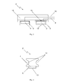
- the two contacts 5, 6 are in the in Fig. 2 shown preferred embodiment rotated by 90 ° to each other in the rest of the grounding contact arranged.
- the contact 6 is firmly connected to the rest of the ground contact, while the contact 5 is movably connected to the rest of the grounding contact.
- the contact 5 is connected to a spring 15 with the remainder of the grounding contact.
- the movable attachment of at least one of the contacts compensates for round or irregular container surfaces and thus improves the electrical contact.
- the grip of the ground contact 2 is in the form of round recesses 12 in the ground contact, thereby making the entire ground contact even more compact.
Abstract
Description
Die vorliegende Erfindung betrifft ein Erdungssystem zum Erden eines Gebindes.The present invention relates to a grounding system for grounding a container.
Das elektrische Erden - also das Herstellen einer elektrischen Verbindung mit einem Erdungspotential - eines Gebindes, z.B. eines Fasses, Kanisters oder sogenannten Big-Bags, ist notwendig beim Befüllen oder Entleeren des Gebindes mit entzündlichen oder explosiven Materialien wie Flüssigkeiten, Gasen oder Pulvern. Ein ungeerdetes Gebinde kann sich z.B. auf Grund der durch den Materialtransfer hervorgerufenen Ladungstrennung elektrostatisch aufladen. Die durch die Aufladung hervorgerufene Potentialdifferenz kann zu einer elektrostatischen Entladung in Form eines Zündfunkens führen, welcher die entzündlichen oder explosiven Materialien entzünden könnte. Das Erden des Gebindes und der Transfereinrichtung, z.B. des Befüllstutzens, verhindert, dass sich eine Potentialdifferenz aufbaut, da alle Teile stets auf dem gleichen Bezugspotential gehalten werden. Durch Erden des Gebindes wird also eine elektrostatische Aufladung als Zündquelle vermieden.The electrical grounding - thus establishing an electrical connection to a grounding potential - of a container, e.g. A barrel, canister or so-called big-bags, is necessary when filling or emptying the container with flammable or explosive materials such as liquids, gases or powders. An ungrounded container can be e.g. Electrostatically charged due to the charge separation caused by the material transfer. The potential difference caused by the charging can lead to an electrostatic discharge in the form of a spark, which could ignite the flammable or explosive materials. The grounding of the container and the transfer device, e.g. the filling nozzle, prevents a potential difference builds up, since all parts are always kept at the same reference potential. By grounding the container thus an electrostatic charge is avoided as a source of ignition.
Zum Erden eines Gebindes werden üblicherweise Erdungsklammern an dem Gebinde angebracht, welche das Gebinde über ein Kabel leitend mit einem Erdungspotential verbinden. Nachteilig ist bei solcher Art Erdung allerdings, dass an dem Gebinde ein geeigneter Vorsprung vorhanden sein muss, um die Erdungsklammer daran anzubringen. Bei Fässern findet sich ein geeigneter Vorsprung üblicherweise in Form einer Falz, welche den Deckel mit der Mantelfläche des Fasses verbindet. Das Anbringen einer Erdungsklammer kann hier jedoch nachteilig sein, weil die an der Falz angebrachte Erdungsklammer häufig nach oben hin absteht und dadurch der Befüllungsanlage im Weg ist. Die Verwendung von Erdungsklammern ist gänzlich unmöglich, wenn die zu erdenden Gebinde, wie z.B. Fässer, nebeneinander z.B. auf einer Palette angeordnet sind. In diesem Fall ist es nicht möglich, an der Falz eines Fasses eine Erdungsklammer anzubringen, da ein benachbartes Fass im Weg ist. Schließlich kommt es häufig vor, dass die Falz durch die Klammer beschädigt z.B. verbogen wird, was insbesondere an unmittelbar sichtbaren Stellen nachteilig ist.For grounding a container usually grounding brackets are attached to the container, which conductively connect the container via a cable with a ground potential. A disadvantage of such type grounding, however, that on the container a suitable projection must be present in order to attach the earthing clamp to it. In barrels, a suitable projection is usually in the form of a fold, which connects the lid with the lateral surface of the barrel. However, the attachment of a grounding clip can be disadvantageous here because the attached to the fold earthing clamp often protrudes upwards and thus the filling plant in the way. The use of earthing clamps is completely impossible if the containers to be grounded, such as barrels, are arranged side by side eg on a pallet. In this case, it is not possible to attach a grounding clip to the crease of a barrel as there is an adjacent cask in the way. Finally, it often happens that the fold is damaged by the clamp, for example, bent, which is particularly disadvantageous in immediately visible places.
Der vorliegenden Erfindung liegt daher die Aufgabe zugrunde, die oben beschriebenen Nachteile aus dem Stand der Technik zu beseitigen.The present invention is therefore based on the object to eliminate the disadvantages of the prior art described above.
Diese Aufgabe wird gelöst durch ein Erdungssystem gemäß unabhängigem Anspruch 1, einen Erdungskontakt gemäß Anspruch 9 und ein Verfahren zum Erden eines Gebindes gemäß Anspruch 10. Vorteilhafte Weiterbildungen ergeben sich jeweils aus den Unteransprüchen.This object is achieved by a grounding system according to
Das erfindungsgemäße Erdungssystem zum Erden eines Gebindes weist einen Erdungskontakt mit zumindest einem Magneten und zumindest zwei Kontakten auf, wobei die zumindest zwei Kontakte aus elektrisch leitfähigem Material bestehen, und wobei die zumindest zwei Kontakte in dem Erdungskontakt untereinander elektrisch isoliert sind. Außerdem weist das erfindungsgemäße Erdungssystem eine Widerstandsmessschaltung auf, welche geeignet ist, einen elektrischen Widerstandswert zu messen. Ferner weist das erfindungsgemäße Erdungssystem einen ersten elektrischen Leiter auf, welcher ein erster der zumindest zwei Kontakte mit einer Erdung verbindet, einen zweiten elektrischen Leiter, welcher einen zweiten der zumindest zwei Kontakte mit der Widerstandsmessschaltung verbindet und einen dritten elektrischen Leiter, welcher die Widerstandsmessschaltung mit der Erdung verbindet.The earth system according to the invention for grounding a container has a grounding contact with at least one magnet and at least two contacts, wherein the at least two contacts made of electrically conductive material, and wherein the at least two contacts are electrically insulated in the ground contact with each other. In addition, the grounding system according to the invention has a resistance measuring circuit which is suitable for measuring an electrical resistance value. Furthermore, the earthing system according to the invention comprises a first electrical conductor connecting a first of the at least two contacts to a ground, a second electrical conductor connecting a second of the at least two contacts to the resistance measuring circuit and a third electrical conductor connecting the resistance measuring circuit to the ground Grounding connects.
Das erfindungsgemäße Erdungssystem zum Erden eines Gebindes löst die oben beschriebene Aufgabe, da der Erdungskontakt mit Hilfe des zumindest einen Magneten an einer beliebigen Stelle des zu erdenden Gebindes angebracht werden kann. Insbesondere können mit dem erfindungsgemäßen Erdungssystem nun auch Gebinde geerdet werden, welche auf einer Palette angeordnet sind und an welchen eine Erdungsklammer nicht oder nur unter Schwierigkeiten befestigt werden kann. Auch werden Beschädigungen an einer Falz des Gebindes vermieden.The earth system according to the invention for grounding a container solves the above-described problem, since the grounding contact can be attached with the help of at least one magnet at any point of the container to be grounded. In particular, can now be grounded with the grounding system according to the invention and containers which are arranged on a pallet and to which a grounding clamp can not be attached or only with difficulty. Also, damage to a fold of the container can be avoided.
In einer vorteilhaften Weiterbildung des Erdungssystems weisen die zumindest zwei Kontakte Zähne, Noppen oder Krallen auf. Durch eine derartige Oberflächengestaltung wird der elektrische Kontakt zwischen den Kontakten und dem Gebinde verbessert, wodurch gewährleistet wird, dass ein eventuell von dem Gebinde über die Kontakte zur Erdung abfließender Strom gemäß dem Ohmschen Gesetz (U=R·I) eine möglichst kleine Potentialdifferenz hervorruft. Kleine Potentialdifferenzen minimieren die Wahrscheinlichkeit einer elektrostatischen Entladung und eines damit verbundenen Zündfunkens. Die Verbesserung des elektrischen Kontaktes durch die Zähne oder Krallen ist darauf zurückzuführen, dass sie eine Oxyd- oder Korrosionsschicht, welche häufig auf den Oberflächen von Metallgebinden zu finden ist, durchdringen und die darunter liegende leitende Schicht kontaktieren. Zähne oder Krallen können auch durch eine möglicherweise vorhandene Beschichtung wie z.B. eine Lackschicht des Gebindes dringen und so einen elektrische Kontakt zwischen der darunter liegenden leitenden Schicht und den Kontakten herstellen.In an advantageous development of the grounding system, the at least two contacts teeth, nubs or claws on. By means of such a surface design, the electrical contact between the contacts and the container is improved, which ensures that any current flowing away from the container via the contacts to the ground causes, according to Ohm's law ( U = R * I ), the smallest possible potential difference. Small potential differences minimize the likelihood of electrostatic discharge and associated spark. The improvement of the electrical contact by the teeth or claws is due to the fact that they penetrate an oxide or corrosion layer, which is often found on the surfaces of metal containers, and contact the underlying conductive layer. Teeth or claws may also penetrate through a possibly existing coating, such as a lacquer layer of the container, thus establishing electrical contact between the underlying conductive layer and the contacts.
In einer weiteren vorteilhaften Weiterbildung des Erdungssystems weisen die Zähne, Noppen oder Krallen einen Radius auf, d.h. ihre Ecken und/oder Kanten sind abgerundet, so dass das Gebinde nicht beschädigt wird, wenn die Kontakte mit dem Gebinde in Kontakt kommen. Dies ist vorteilhaft, falls der Erdungskontakt an einer sichtbaren Stelle des Gebindes angebracht wird, wo eine eventuelle Beschädigung der Gebindeoberfläche den optischen Eindruck des Gebindes beeinträchtigt.In a further advantageous development of the earthing system, the teeth, nubs or claws have a radius, ie their corners and / or edges are rounded, so that the container is not damaged when the contacts come into contact with the container. This is advantageous if the grounding contact is attached to a visible location of the container, where any damage to the container surface affects the visual impression of the container.
In einer weiteren vorteilhaften Weiterbildung bestehen die zumindest zwei Kontakte aus Stahl, Edelstahl, Messing, Leichtmetall oder Kupfer. Diese Materialien weisen eine gute spezifische Leitfähigkeit und damit einen geringen spezifischen Widerstand auf, wodurch eine eventuell vorhandene Potentialdifferenz zwischen dem Gebinde und der Erde minimiert wird.In a further advantageous development, the at least two contacts made of steel, stainless steel, brass, light metal or copper. These materials have a good specific conductivity and thus a low resistivity, whereby a potential potential difference between the container and the earth is minimized.
In einer weiteren vorteilhaften Weiterbildung handelt es sich bei dem zumindest einen Magneten um einen Permanentmagneten. Ein derartiger Magnet hält seine Magnetisierung über einen langen Zeitraum aufrecht und sorgt dafür, dass der Erdungskontakt stets zuverlässig an dem Gebinde haftet.In a further advantageous embodiment, the at least one magnet is a permanent magnet. Such a magnet maintains its magnetization over a long period of time and ensures that the grounding contact always reliably adheres to the container.
In einer weiteren vorteilhaften Weiterbildung weist der Erdungskontakt zwei Magnete und zwei Kontakte auf.In a further advantageous development, the grounding contact has two magnets and two contacts.
In einer weiteren vorteilhaften Weiterbildung sind die zwei Magnete jeweils in den zwei Kontakten angeordnet. Diese Anordnung erlaubt eine Platz sparende Ausgestaltung des Erdungskontakts. Außerdem ist jedem Kontakt unmittelbar räumliche ein Magnet zugeordnet, wodurch jedes der zwei Kontakte optimal an das Gebinde angedrückt wird, so dass eine gute elektrische Verbindung zwischen den Kontakten und dem Gebinde entsteht und der elektrische Übergangswiderstand zwischen dem Gebinde und den Kontakten möglichst klein wird.In a further advantageous development, the two magnets are each arranged in the two contacts. This arrangement allows a space-saving design of the grounding contact. In addition, each contact is assigned a spatial proximity magnet, whereby each of the two contacts is optimally pressed against the container, so that a good electrical connection between the contacts and the container is formed and the electrical contact resistance between the container and the contacts is as small as possible.
In einer weiteren vorteilhaften Weiterbildung weist der Erdungskontakt eine Anzeige auf, welche anzeigt, ob das Gebinde ausreichend geerdet ist. Durch die Anzeige erhält das Bedienpersonal unmittelbar eine Rückmeldung, ob das Gebinde ausreichend geerdet ist, so dass mit dem Befüllen oder Entleeren des Gebindes begonnen werden kann.In a further advantageous development, the ground contact on a display, which indicates whether the container is sufficiently grounded. The display gives the operator immediate feedback as to whether the container is sufficiently grounded, so that the filling or emptying of the container can be started.
In einer weiteren vorteilhaften Weiterbildung bestehen die zumindest zwei Kontakte aus magnetischem Material, so dass die Kraft des zumindest einen Magneten verstärkt wird. Eine höhere Magnetkraft resultiert vorteilhafterweise in einer höheren Anpresskraft und damit in einem verbesserten elektrischen Kontakt zwischen den Kontakten und dem Gebinde.In a further advantageous embodiment, the at least two contacts made of magnetic material, so that the force of the at least one magnet is reinforced. A higher magnetic force advantageously results in a higher contact pressure and thus in an improved electrical contact between the contacts and the container.
Der erfindungsgemäße Erdungskontakt zur Verwendung in einem Erdungssystem zum Erden eines Gebindes weist zumindest einen Magneten und zumindest zwei Kontakte auf, wobei die zumindest zwei Kontakte aus elektrisch leitfähigem Material bestehen und wobei die zumindest zwei Kontakte in dem Erdungskontakt untereinander elektrisch isoliert sind. Das Erdungssystem weist eine Widerstandsmessschaltung auf, welche geeignet ist, einen elektrischen Widerstand zu messen. Ferner weist das Erdungssystem einen ersten elektrische Leiter auf, um den Anschluss eines ersten der zumindest zwei Kontakte mit einer Erdung zu verbinden, einen zweiten elektrischen Leiter, um den Anschluss eines zweiten der zumindest zwei Kontakte mit der Widerstandsmessschaltung zu verbinden und einen dritten elektrischen Leiter, welcher die Widerstandsmessschaltung mit der Erdung verbindet.The earth contact according to the invention for use in a grounding system for grounding a container has at least one magnet and at least two contacts, wherein the at least two contacts made of electrically conductive material and wherein the at least two contacts in the ground contact with each other are electrically insulated. The grounding system has a resistance measuring circuit which is suitable for measuring an electrical resistance. Furthermore, the grounding system has a first electrical conductor for connecting the terminal of a first of the at least two contacts to a ground, a second electrical conductor for connecting the terminal of a second of the at least two contacts to the resistance measuring circuit and a third electrical conductor, which connects the resistance measuring circuit to ground.
Das erfindungsgemäße Verfahren zum Erden einen Gebindes weist den Schritt des Anbringens eines Erdungskontakts auf dem Gebinde auf, wobei der Erdungskontakt zumindest einen Magneten und zumindest zwei Kontakte aufweist, wobei die zumindest zwei Kontakte aus elektrisch leitfähigem Material bestehen, wobei die zumindest zwei Kontakte in dem Erdungskontakt untereinander elektrisch isoliert sind und wobei ein erster der zumindest zwei Kontakte über einen ersten elektrische Leiter mit einer Erdung verbunden ist und ein zweiter der zumindest zwei Kontakte über einen zweiten elektrischen Leiter mit einer Widerstandsmessschaltung verbunden ist und die Widerstandsmessschaltung über einen dritten elektrischen Leiter mit der Erdung verbunden ist. Ferner weist das erfindungsgemäße Verfahren zum Erden eines Gebindes den Schritt des Messens des elektrischen Widerstandswertes mit der Widerstandsmessschaltung auf.The method of grounding a package according to the invention comprises the step of attaching a grounding contact to the package, wherein the grounding contact comprises at least one magnet and at least two contacts, wherein the at least two contacts are made of electrically conductive material, wherein the at least two contacts in the grounding contact wherein a first of the at least two contacts is connected via a first electrical conductor to a ground and a second of the at least two contacts via a second electrical conductor is connected to a resistance measuring circuit and the resistance measuring circuit via a third electrical conductor to the ground connected is. Furthermore, the method according to the invention for grounding a container has the step of measuring the electrical resistance value with the resistance measuring circuit.
Weitere Vorteile und Merkmale der Erfindung sind der nachfolgenden detaillierten Beschreibung zu entnehmen, in welcher die Erfindung detaillierter und in Bezug auf die in den beigefügten Zeichnungen dargestellten Ausführungsbeispiele beschrieben wird.Further advantages and features of the invention will become apparent from the following detailed description, in which the invention will be described in more detail and with reference to the embodiments illustrated in the accompanying drawings.
In den Zeichnungen zeigt:
- Fig. 1
- eine schematische Ansicht einer Ausführungsform eines erfin- dungsgemäßen Erdungssystems zum Erden eines Gebindes,
- Fig. 2
- eine Ansicht einer bevorzugten Ausführungsform eines Erdungs- kontakts des erfindungsgemäßen Erdungssystems.
- Fig. 3
- eine Ansicht einer bevorzugten Ausführungsform eines Erdungs- kontakts des erfindungsgemäßen Erdungssystems.
- Fig. 1
- 1 is a schematic view of an embodiment of a grounding system according to the invention for grounding a container,
- Fig. 2
- a view of a preferred embodiment of a grounding contact of the grounding system according to the invention.
- Fig. 3
- a view of a preferred embodiment of a grounding contact of the grounding system according to the invention.
Beispielhaft ist in
Die Magnete 3, 4 haben in dem gezeigten Ausführungsbeispiel einen rechteckigen Querschnitt. Denkbar sind jedoch auch andere Querschnitte wie z.B. rund. Bei den Magneten kann es sich um Permanentmagnete auf der Basis von z.B. Eisen, Kobalt, Nickel oder entsprechender Legierungen davon handeln. Die Magnete können aber auch als Elektromagnete z.B. in der Form von Spulen ausgeführt sein. In diesem Fall kann das Bedienpersonal z.B. mittels eines Schalters den Stromfluss durch die Spulen einschalten, wenn der Erdungskontakt an einem Gebinde angebracht wird. Entsprechend kann mittels des Schalters der Stromfluss durch die Spulen ausgeschaltet werden, wenn der Erdungskontakt von dem Gebinde gelöst werden soll. Die Realisierung der Magnete als Elektromagnete bietet sich an, wenn eine hohe Haltekraft gewünscht wird ohne dass die starke Magnetkraft das Anbringen oder Entfernen des Erdungskontaktes behindert oder unnötig erschwert. Die Funktion der Magnete 3, 4 besteht darin, den Erdungskontakt 2 an die Oberfläche des Gebindes zu drücken, d.h. eine Kraft in Richtung der Gebindeoberfläche zu erzeugen. Durch diese Kraft wird der Erdungskontakt 2 an dem Gebinde fixiert und eine elektrische Verbindung zwischen den Kontakten 5, 6 und dem Gebinde hergestellt. Durch die Kraft der Magnete haftet der Erdungskontakt selbständig an dem Gebinde.The
Die Kontakte sind in dem in
Die beispielhaften Kontakte weisen ferner Krallen 13 auf. Beim Anbringen des Erdungskontaktes an einem Gebinde kommen die Krallen 13 in Kontakt mit derThe exemplary contacts further include
Gebindeoberfläche. Dadurch, dass die Krallen 13 Spitzen aufweisen, ist die κontaktfläche zwischen den Kontakten 5, 6 und dem Gebinde relativ klein, wodurch ein hoher Druck durch die Haltekraft der Magnete 3, 4 an der Kontaktfläche entsteht. Dies sorgt für eine gute elektrische Verbindung zwischen den Kontakten 5, 6 und dem Gebinde und damit für eine verbesserte Erdung. Außerdem wird auf diese Weise gewährleistet, dass überhaupt eine elektrische Verbindung entsteht, wenn das Gebinde z.B. mit einer Lackschicht überzogen ist. In diesem Fall durchdringen die Spitzen der Krallen 13 die Lackschicht und sorgen so für die nötige elektrische Verbindung. Statt der Krallen sind auch andere Formen wie z.B. Zähne oder Noppen vorstellbar. Auch können die Spitzen der Krallen, Zähne oder Noppen einen Radius aufweisen, d.h. abgerundet sein, so dass das Gebinde nicht beschädigt wird, wenn die Kontakte in Kontakt mit dem Gebinde kommen.Container surface. Characterized in that the
In
In dem in
Wird der Erdungskontakt 2 an einem Gebinde angebracht, so entsteht eine Stromschleife aus den zwei Kontakten 5, 6, dem Gebinde, den elektrischen Leitern 8, 10, 11 und der Erdung 9. Das Widerstandsmessgerät 7 kann den elektrischen Widerstandwert dieser Stromschleife messen.If the
Beispielhaft ist in
Grund für einen großen Übergangswiderstand zwischen Gebinde und Kontakt 5 kann zum Beispiel sein, dass der Erdungskontakt nicht richtig an dem Gebinde angebracht ist, d.h. die beiden Kontakte 5, 6 das Gebinde nicht ausreichend kontaktieren. Grund dafür kann z.B. sein dass das Gebinde mit einer Lackschicht überzogen ist, welche eine gute elektrische Verbindung zwischen dem Gebinde und den Kontakten 5, 6 verhindert. Deshalb kann beispielsweise, wenn der gemessene Widerstandswert der Stromschleife den voreingestellten Schwellwert überschreitet, ein akustisches und/oder optisches Signal ausgegeben werden, da ein solches Überschreiten ein nicht korrektes Erden des Gebindes und damit eine erhöhte Entzündungs- oder Explosionsgefahr bedeuten kann. Zusätzlich oder stattdessen kann die Schwellwertschaltung 14 aber auch einen Transfervorgang, also ein Befüllen oder Entleeren des Gebindes, unterbrechen, um das Entzündungs- oder Explosionsrisiko zu vermindern.The reason for a large contact resistance between the container and the
In den
Die beiden Kontakte 5, 6 sind in der in
Wie am besten in
Claims (15)
Priority Applications (1)
| Application Number | Priority Date | Filing Date | Title |
|---|---|---|---|
| EP09162400A EP2262060A1 (en) | 2009-06-10 | 2009-06-10 | Grounding system for grounding a container |
Applications Claiming Priority (1)
| Application Number | Priority Date | Filing Date | Title |
|---|---|---|---|
| EP09162400A EP2262060A1 (en) | 2009-06-10 | 2009-06-10 | Grounding system for grounding a container |
Publications (1)
| Publication Number | Publication Date |
|---|---|
| EP2262060A1 true EP2262060A1 (en) | 2010-12-15 |
Family
ID=41259690
Family Applications (1)
| Application Number | Title | Priority Date | Filing Date |
|---|---|---|---|
| EP09162400A Withdrawn EP2262060A1 (en) | 2009-06-10 | 2009-06-10 | Grounding system for grounding a container |
Country Status (1)
| Country | Link |
|---|---|
| EP (1) | EP2262060A1 (en) |
Cited By (2)
| Publication number | Priority date | Publication date | Assignee | Title |
|---|---|---|---|---|
| CN103210316A (en) * | 2011-01-17 | 2013-07-17 | 日东电工株式会社 | Earth device |
| CN109273876A (en) * | 2018-10-24 | 2019-01-25 | 程海明 | A kind of novel electric power system arc-extinguishing grounding device |
Citations (9)
| Publication number | Priority date | Publication date | Assignee | Title |
|---|---|---|---|---|
| US3518607A (en) * | 1968-04-12 | 1970-06-30 | Richard F Reel | Safety ground device |
| EP0238017A2 (en) * | 1986-03-21 | 1987-09-23 | BARTEL, Bernhard | Electrical device with at least one electrical consumer unit disposed on and removable from a surface |
| US5004425A (en) * | 1989-10-10 | 1991-04-02 | Jes, L.P. | Magnetic snap assembly for connecting grounding cord to electrically conductive body band |
| DE4011198A1 (en) * | 1990-04-04 | 1991-10-10 | Peter Graue | Supply system for electrical loads - has strip foil contacts set into surface to engage with contacts of load devices |
| US5290191A (en) * | 1991-04-29 | 1994-03-01 | Foreman Kevin G | Interface conditioning insert wafer |
| WO2001022533A1 (en) * | 1999-09-23 | 2001-03-29 | Factor Tools International As | Grounding terminal |
| JP2001289890A (en) * | 2000-04-04 | 2001-10-19 | Dai Nippon Construction | Apparatus for measuring specific resistance of ground |
| DE202004008334U1 (en) * | 2004-05-25 | 2004-09-02 | Geb, Nikolaus | Wall outlet socket fitting strip for portable electrical operating devices has an in-built differential current meter for measuring earth conductor current and contact-voltage current |
| DE102007010193A1 (en) * | 2007-02-18 | 2008-08-21 | Hidde, Axel R., Dr. | Electrical status display for maritime switching equipment e.g. for containers storage on board ship, has electrical state of each phase of system queried at measurement- and test-points ready for optical display |
-
2009
- 2009-06-10 EP EP09162400A patent/EP2262060A1/en not_active Withdrawn
Patent Citations (9)
| Publication number | Priority date | Publication date | Assignee | Title |
|---|---|---|---|---|
| US3518607A (en) * | 1968-04-12 | 1970-06-30 | Richard F Reel | Safety ground device |
| EP0238017A2 (en) * | 1986-03-21 | 1987-09-23 | BARTEL, Bernhard | Electrical device with at least one electrical consumer unit disposed on and removable from a surface |
| US5004425A (en) * | 1989-10-10 | 1991-04-02 | Jes, L.P. | Magnetic snap assembly for connecting grounding cord to electrically conductive body band |
| DE4011198A1 (en) * | 1990-04-04 | 1991-10-10 | Peter Graue | Supply system for electrical loads - has strip foil contacts set into surface to engage with contacts of load devices |
| US5290191A (en) * | 1991-04-29 | 1994-03-01 | Foreman Kevin G | Interface conditioning insert wafer |
| WO2001022533A1 (en) * | 1999-09-23 | 2001-03-29 | Factor Tools International As | Grounding terminal |
| JP2001289890A (en) * | 2000-04-04 | 2001-10-19 | Dai Nippon Construction | Apparatus for measuring specific resistance of ground |
| DE202004008334U1 (en) * | 2004-05-25 | 2004-09-02 | Geb, Nikolaus | Wall outlet socket fitting strip for portable electrical operating devices has an in-built differential current meter for measuring earth conductor current and contact-voltage current |
| DE102007010193A1 (en) * | 2007-02-18 | 2008-08-21 | Hidde, Axel R., Dr. | Electrical status display for maritime switching equipment e.g. for containers storage on board ship, has electrical state of each phase of system queried at measurement- and test-points ready for optical display |
Cited By (4)
| Publication number | Priority date | Publication date | Assignee | Title |
|---|---|---|---|---|
| CN103210316A (en) * | 2011-01-17 | 2013-07-17 | 日东电工株式会社 | Earth device |
| EP2669692A1 (en) * | 2011-01-17 | 2013-12-04 | Nitto Denko Corporation | Earth device |
| EP2669692A4 (en) * | 2011-01-17 | 2014-07-30 | Nitto Denko Corp | Earth device |
| CN109273876A (en) * | 2018-10-24 | 2019-01-25 | 程海明 | A kind of novel electric power system arc-extinguishing grounding device |
Similar Documents
| Publication | Publication Date | Title |
|---|---|---|
| EP1825231A2 (en) | Device for determining and/or monitoring the fill-level process variable of a substance in a container | |
| DE202010017635U1 (en) | Current transformer unit | |
| EP2262060A1 (en) | Grounding system for grounding a container | |
| DE102007018669A1 (en) | Battery pole measuring clamp has battery pole clamp and measuring resistance connects with its connection element with battery pole clamp in firmly bonded manner | |
| EP2710241B1 (en) | Storage vessel for a liquid | |
| WO2014040830A1 (en) | Current converter with interchangeable head | |
| EP2672278A1 (en) | Measuring instrument, in particular a voltage tester | |
| WO2013034443A1 (en) | Electric connector with contact protection | |
| DE1230880B (en) | Electric switch with sliding actuator | |
| DE202020105266U1 (en) | Grounding device | |
| EP2237648A2 (en) | Modified contact for earthing | |
| EP0119458A2 (en) | Electric igniter | |
| DE102018200621A1 (en) | Measuring arrangement with a measuring resistor | |
| DE10125355A1 (en) | Method and device for determining the level in a fuel tank | |
| DE102010060387A1 (en) | Electrical connector device for connector-counter connector plug-in system of current transformer, has short circuit bridge element displaceable by counter-contact structures slid into recess | |
| EP0978319A1 (en) | Powder spray device with external and internal charging | |
| CH717091A2 (en) | Clamp meter. | |
| DE2445350A1 (en) | METHOD AND DEVICE FOR DETERMINING FAULTS IN MAGNETIZABLE OBJECTS | |
| DE102011007954B4 (en) | busbar | |
| EP2866234B1 (en) | Demagnetisation coil | |
| WO2004044597A2 (en) | Device and method for determining the absence of application of stresses on polyphase electrical transmission lines | |
| EP3433871B1 (en) | Device for measuring a condition of an electric switch, electric switch and method for measuring a condition of an electric switch | |
| DE102008010626A1 (en) | Motor vehicle, has insulator arranged between ground wire and line connection, where ground wire and/or line connection are designed in such manner that spark discharge is possible between ground wire and line connection | |
| EP3796474A2 (en) | Connection device for electrically contacting an electrical device | |
| DE1951050A1 (en) | Device for displaying an arc flash |
Legal Events
| Date | Code | Title | Description |
|---|---|---|---|
| PUAI | Public reference made under article 153(3) epc to a published international application that has entered the european phase |
Free format text: ORIGINAL CODE: 0009012 |
|
| AK | Designated contracting states |
Kind code of ref document: A1 Designated state(s): AT BE BG CH CY CZ DE DK EE ES FI FR GB GR HR HU IE IS IT LI LT LU LV MC MK MT NL NO PL PT RO SE SI SK TR |
|
| STAA | Information on the status of an ep patent application or granted ep patent |
Free format text: STATUS: THE APPLICATION IS DEEMED TO BE WITHDRAWN |
|
| 18D | Application deemed to be withdrawn |
Effective date: 20110616 |