EP2241902A1 - Determinition of the position of a mobile transmitter comprising an interface human/machine to trigger the positioning - Google Patents
Determinition of the position of a mobile transmitter comprising an interface human/machine to trigger the positioning Download PDFInfo
- Publication number
- EP2241902A1 EP2241902A1 EP10003443A EP10003443A EP2241902A1 EP 2241902 A1 EP2241902 A1 EP 2241902A1 EP 10003443 A EP10003443 A EP 10003443A EP 10003443 A EP10003443 A EP 10003443A EP 2241902 A1 EP2241902 A1 EP 2241902A1
- Authority
- EP
- European Patent Office
- Prior art keywords
- location
- reference area
- portable device
- probes
- determining
- Prior art date
- Legal status (The legal status is an assumption and is not a legal conclusion. Google has not performed a legal analysis and makes no representation as to the accuracy of the status listed.)
- Granted
Links
Images


Classifications
-
- G—PHYSICS
- G01—MEASURING; TESTING
- G01S—RADIO DIRECTION-FINDING; RADIO NAVIGATION; DETERMINING DISTANCE OR VELOCITY BY USE OF RADIO WAVES; LOCATING OR PRESENCE-DETECTING BY USE OF THE REFLECTION OR RERADIATION OF RADIO WAVES; ANALOGOUS ARRANGEMENTS USING OTHER WAVES
- G01S5/00—Position-fixing by co-ordinating two or more direction or position line determinations; Position-fixing by co-ordinating two or more distance determinations
- G01S5/02—Position-fixing by co-ordinating two or more direction or position line determinations; Position-fixing by co-ordinating two or more distance determinations using radio waves
- G01S5/08—Position of single direction-finder fixed by determining direction of a plurality of spaced sources of known location
-
- H—ELECTRICITY
- H04—ELECTRIC COMMUNICATION TECHNIQUE
- H04W—WIRELESS COMMUNICATION NETWORKS
- H04W64/00—Locating users or terminals or network equipment for network management purposes, e.g. mobility management
Definitions
- the invention relates to a method for detecting the location of an object within a reference area. More particularly, the invention relates to a method for locating a portable device emitting an electric field and / or a magnetic field within a reference area.
- Microsoft Surface® is an innovative human / machine interface that has recently been introduced and is described in US Patent Application No. 2006/0284874 .
- This patent application describes a method and a device for detecting one or more objects with respect to a display screen on which images (for example photos) are projected.
- An infrared light source directs infrared light toward the display screen.
- the infrared light is then reflected by objects on or near the display screen and this reflected light is captured by a digital video camera.
- the presence and / or movement of objects, such as the hands of a user are thus detected by the system, and a computer connected to the projector and the camera can calculate, by means of optical flow algorithms, what action should be performed and what should be displayed on the display screen.
- This application allows one or more users to perform actions such as translating, rotating, and resizing items projected on the display surface.
- NFC devices such as NFC PDAs or NFC mobile phones include an NFC reader that emits an RF magnetic field oscillating for example at 13.56 MHz.
- NFC Near Field Communication
- mobile phones conventionally, mobile phones also emit a UHF electromagnetic field having an electric field component to communicate with a mobile telephone network.
- Embodiments of the invention include the observation that electric fields or magnetic fields emitted by such portable devices can be used to detect their location or displacement within a reference area.
- Embodiments of the invention also include the observation that portable devices emitting an electric field or a magnetic field can be used as new types of human / machine interfaces to initiate interactive operations according to their location within a reference area.
- embodiments of the invention relate to a method for locating a portable emitting device emitting an electric field and / or a magnetic field, such as a mobile phone emitting an electric field or an NFC device emitting a field.
- magnetic method comprising the steps of: defining a reference area, having at least one electric field and / or magnetic field probe near or within the reference area, arranging the portable device to inside the reference area, receiving from the probe a detection signal of the electric field and / or the magnetic field emitted by the portable device, and analyzing the detection signal provided by the probe and deducing the location of the device portable within the reference area.
- the analysis of the detection signal comprises the steps of analyzing the amplitude of the detection signal to provide an amplitude value, and determining from the amplitude value the location of the detection signal. portable device within the reference area.
- the analysis of the detection signal comprises the steps of analyzing the phase of the detection signal to provide a phase value, and determining from the phase value the location of the portable device to inside the reference area.
- the method comprises the steps of: disposing at least two electric field and / or magnetic field probes near or within the reference area, receiving probes at least two signals of detecting and determining the location of the portable device within the reference area from the phase difference between the detection signals.
- the method comprises the steps of: disposing at least two electric field and / or magnetic field probes near or within the reference area, receiving probes at least two signals of detecting and determining the location of the portable device within the reference area from the amplitudes of the detection signals.
- the method comprises the steps of: arranging at least three electric field and / or magnetic field probes near or within the reference area, receiving probes at least three signals of detecting, determining a first phase difference between a first pair of detection signals, determining at least a second phase difference between a second pair of detection signals, and determining the location of the portable device within the area reference from the first and second phase differences.
- the method comprises the steps of: defining predetermined locations within the reference area, analyzing the detection signal provided by the probe, and deriving on which predetermined location the device is located portable.
- Embodiments of the invention also relate to a method for performing at least one interactive action, comprising a step of locating a portable device. transmitter within a reference area according to the method described above, and a step of initiating the interactive action according to the location of the portable device within the reference area.
- the initiation of the interactive action includes a step of providing interactive control signals to an external device configured to perform the interactive action.
- Embodiments of the invention also relate to a human / machine interface system for use with a portable device emitting an electric field and / or a magnetic field, such as a mobile phone emitting an electric field or an NFC device emitting a magnetic field, and comprising at least one electric field and / or magnetic field probe providing a detection signal, a location determining device, the location determining device being configured to analyze the detection signal, in deriving the location of the portable device within a reference area, and initiating at least one interactive action depending on the location of the portable device.
- a portable device emitting an electric field and / or a magnetic field such as a mobile phone emitting an electric field or an NFC device emitting a magnetic field, and comprising at least one electric field and / or magnetic field probe providing a detection signal, a location determining device, the location determining device being configured to analyze the detection signal, in deriving the location of the portable device within a reference area, and initiating at least one interactive action depending on the location of the portable device.
- the location determining device is configured to determine the location of the portable device from the amplitude value of the detection signal.
- the location determining device is configured to determine the location of the portable device from the phase value of the detection signal.
- the system comprises at least two electric field and / or magnetic field probes near or within the reference area, providing detection signals, and the location determining device is configured to determine the location of the portable device within the reference area from the phase difference between the detection signals.
- the system comprises at least two electric field and / or magnetic field probes near or within the reference area, providing detection signals, and the location determining device is configured to determine the location of the device portable within the reference area from the amplitudes of the detection signals.
- the system comprises at least three electric field and / or magnetic field probes near or within the reference area, the probes providing detection signals, and the device for determining the detection field. location is configured to determine a first phase difference between a first pair of sense signals, determine at least a second phase difference between a second pair of sense signals, and determine the location of the portable device within a second pair of sense signals; the reference area from the first and second phase differences.
- the location determining device is configured to store predetermined locations within the reference area, associating at least one interactive action at each predetermined location of the portable device, determining from the signal sensing on which predetermined location is located the portable device, and initiating the interactive action that is associated with the location of the portable device.
- the location determining device is configured to record, for each predetermined location, a set of amplitude and / or phase values of the detection signals when the portable device is placed on the location.
- Embodiments of a method for locating a portable transmitting device include the steps of defining a reference area and arranging electric field and / or magnetic field probes around the area of the invention. reference.
- a portable device emitting an electric field and / or a magnetic field is placed inside the reference area, and the probes provide detection signals.
- Each detection signal is the image of the electric or magnetic field emitted by the portable device as detected by the probe in question, and its amplitude and its phase depend on the distance between the portable device and the probe.
- the detection signals are used to determine the location of the portable device.
- the human-machine interface system receives detection signals provided by the probes and evaluates the location of the portable device within the the reference area. Operations may be assigned to the various locations on the reference area, and are executed when a user places the portable device at a certain location.
- a first embodiment of the method is illustrated on the figure 1 .
- a reference area RA1 is defined.
- the RA1 reference area can be on a surface such as a table or desk, the floor, a wall, etc. Therefore, it can be horizontal, vertical, or have any orientation or any shape, for example square, circular, etc.
- the reference area has a surface of the order of a few tens of square centimeters to a maximum of a few square meters, corresponding to the maximum amplitude of the movements that the user of the telephone can make with his arm and possibly his body, in a piece of usual dimensions.
- Two probes P1, P2 are arranged opposite each other on sides of the reference area RA1.
- the reference area RA1 is substantially a one-dimensional space along an axis X in which the probes P1, P2 are arranged.
- the reference area may be considered as a line coinciding with the X axis, or a fine rectangle aligned with the X axis, having a small width and a length equal to the distance between the probes P1, P2.
- the probes P1, P2 illustrated on the figure 1 are electric field probes.
- the probe P1 comprises, for example, a conducting wire W1 and a voltage probe EP1 in order to detect a voltage in the conducting wire.
- the probe P2 comprises a conducting wire W2 and an electric field probe EP2 in order to detect a voltage in the conducting wire W2.
- Probes P1, P2 are separated from each other by a known distance D12.
- the probes P1, P2 detect the electric field emitted by the portable device and provide detection signals S1, S2.
- Knowing the distance D12 makes it possible to determine the location of the portable device on the X axis without requiring a calibration step.
- the location of the portable device H1 can be determined by means of the phase difference between the signals S1, S2 or the difference in amplitude between the signals S1, S2, as will be explained later.
- D1 and D2 shall be determined.
- the amplitude of the signals detected by the probes is used to determine the location of the portable device.
- the probe P1 detects an amplitude signal M1 and the probe P2 detects a signal of amplitude M2.
- M0 being the maximum amplitude detected when the distance between the probes and the emitter object is zero
- K2 being a constant representing the slope of the function F which is determined by means of a calibration step.
- the figure 1 also illustrates an embodiment of a MMIS1 human / machine interface system implementing one or both of the methods described above.
- the MMIS1 system comprises probes P1, P2 and also includes an ADC1 analog-to-digital converter and a location determiner LDD1.
- the detection signals S1, S2 provided by the probes P1, P2 are digitized by the converter ADC1, which supplies the corresponding digitized signals DS1, DS2 to the device LDD1.
- the device LDD1 comprises an SD storage device containing programs and algorithms for analyzing the DS1, DS2 signals, extracting the phase difference or their amplitude or both, and executing algorithms to find the distances D1, D2 and so on. locate the portable device H1 according to at least one of the methods described above.
- a calibration step is performed in order to define the constant K2 or to define the amplitude M0 at a zero distance from the probes (see the equations alternatives 10 ', 11' above).
- the user must place the portable device in two different locations with respect to at least one probe, assuming that the probes are identical, in order to define K2.
- the user must place the portable device right next to at least one probe, in order to define M0.
- the device LDD1 may optionally be equipped with a display unit DU.
- the analog-digital converter ADC1 can also be part of the LDD1 device.
- the LDD1 device is a personal computer
- the SD storage device is a hard disk
- the display unit DU is a monitor.
- the monitor can have as interface a touch screen and / or the personal computer may also be equipped with an input member such as a keyboard (not shown).
- the device LDD1 provides interactive control signals IS1, IS2 ... ISi based on actions assigned to the various locations of the portable device. These control signals are used to initiate operations such as “Turn on the light”, “Turn off the light”, “Turn on the television”, “Turn off the television”, “Turn on the radio”, “Turn off the radio”, “Next slide” » « Previous slide »(for an image projection system during a presentation) etc. These operations are actions defined by the user, an administrator, or by the manufacturer or system vendor.
- a preliminary step may be performed before the system is used to define the actions to be performed when the portable device H1 is detected in the various locations of the reference area. It can consist of choosing actions from a predefined menu.
- the reference area could be divided into several different zones (not shown), such as a zone Z1 near the probe P1, a zone Z2 in the center, and a zone Z3 near the probe P2.
- each location can also be marked with symbols, photos, words, etc. to indicate to the user where to place the portable device for an action to be performed.
- Preconfigured templates for example an icon representing a light bulb to indicate that the light will turn on, can be provided.
- these models which may also indicate where to place the probes, may vary depending on the type of portable device to be used, the number of probes, the size and shape of the reference area, etc.
- Another example of use is to connect the home / machine interface system to an audio system or to light, and to use the movement of the portable device as a sliding switch to increase or decrease the volume or intensity of the light.
- the system MMIS1 is configured so that as the portable device is moved to the probe P1, the amplitude M1 increases as the amplitude M2 decreases and the volume or intensity of the light increases. Conversely, as the portable device is moved to the probe P2, the amplitude M2 increases as the amplitude M1 decreases, and the volume or intensity of the light decreases.
- the probes P1, P2 may also be magnetic field probes, for example antenna coils configured to detect a magnetic field emitted by a portable device comprising a NFC (Near Field Communication) controller.
- NFC Near Field Communication
- the wavelength ⁇ is equal to 22.1 m and represents the maximum distance between the P1 probes.
- P2 if the phase difference method is used to locate the portable device.
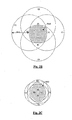
- a second embodiment of a method for locating a portable transmitter device within a reference area is illustrated on the Figure 2A .
- a two-dimensional reference area RA2 is defined. Locations are defined within the area with respect to an orthogonal coordinate system Oxy having a center O, an x-axis, and a y-axis.
- Two probes P1, P2 are arranged opposite each other on sides of the reference area RA2, at points F1, F2 which are for example located on the X axis (the x axis being for example defined as passing through F1, F2 ).
- Two other probes P3, P4 are arranged opposite each other on sides of the reference area RA2, for example at points F3, F4 located for example near the y-axis. It is assumed here that the respective x, y coordinates of the points F1, F2, F3, F4 are known.
- Probes P1-P4 are for example electric field probes of the type described above, or magnetic field probes configured to operate with an NFC portable device.
- the portable device H1 is then arranged inside the reference area RA2 at a point E1.
- the probes P1, P2, P3, P4 detect the electric field or the magnetic field emitted by the portable device and provide detection signals S1, S2, S3, S4.
- the location E1 of the portable device H1 is determined by means of the phase difference between the signals S1 and S2, S3 and S4.
- the hyperbola can be drawn in the Oxy plane as illustrated on the Figure 2A since ⁇ 1- ⁇ 2, ⁇ and K1 are known (or its points can be simply calculated by a location determination device).
- the hyperbole includes the curves H12, H12 '.
- the second hyperbola can also be drawn in the Oxy plane as illustrated on the Figure 2A , since ⁇ 1- ⁇ 2, ⁇ and K1 are known, or its calculated points.
- the hyperbola comprises the curves H34, H34 '.
- the determination of the actual location among the four possible locations is performed using the sign of the phase differences or the sign d differences between the magnitudes M1, M2, M3, M4 of the signals S1, S2, S3, S4 to determine in which quadrant of the plane Oxy is the desired intersection point, the four quadrants being for example defined as follows: x> 0 and y> 0, x> 0 and y ⁇ 0, x ⁇ 0 and y ⁇ 0, x ⁇ 0 and y> 0.
- the identification of the quadrant in which the portable device is located i.e., the quadrant in which the desired intersection point is located, is performed prior to searching for the intersection of the hyperbolas. , in order to simplify the calculation by avoiding having to look for the four points of intersection.
- the Figure 2B schematically illustrates the shape of the reference area RA2 obtained with the four probes situated at the points F1, F2, F3, F4, within which the distances D1, D2, D3 and D4 are less than or equal to the length of d wave ⁇ .
- the reference area RA2 is represented by a shaded area and corresponds to the intersection zone of four circles C1, C2, C3, C4 whose respective centers are the points F1, F2, F3, F4 and each having a radius R equal to ⁇ .
- the distance between F1 and F2 and the distance between F3 and F4 is close to ⁇ and F1-F4 are close to the boundaries of the reference area.
- Figure 2C schematically illustrates the shape of the reference area RA2 when the distance between F1 and F2 and the distance between F3 and F4 are well below ⁇ .
- F1, F2, F3, F4 lie within the reference area RA2.
- the embodiment of the method just described is capable of many other embodiments.
- the method can use the phase differences ⁇ 1- ⁇ 3, ⁇ 2- ⁇ 4 and the corresponding hyperbolas and their points of intersection, or the phase differences ⁇ 1- ⁇ 4, ⁇ 2- ⁇ 3 and the corresponding hyperbolas and their points of intersection.
- the method instead of using four probes, it is possible to use only three P1, P2, P3, and the method can use the phase differences ⁇ 1- ⁇ 3, ⁇ 2- ⁇ 3 and the corresponding hyperbolas and their dots. 'intersection.
- the hyperbola can be plotted in the Oxy plane if K2 is known (alternatively its points can be calculated by means of a location determination device).
- the second hyperbola can also be plotted in the Oxy plane, where its points are simply calculated. Once the hyperbolas are drawn or their points are simply calculated, four points of intersection E1, E1 ', E1 ", E1"' are found, as before.
- the point where the portable device is actually located here the point E1, must be chosen from the points E1, E1 ', E1 ", E1"'.
- the determination of the actual location between the four possible locations is made by using the sign of the differences between the amplitudes M1, M2, M3, M4 of the signals S1, S2, S3, S4 to determine in which quadrant of the plane Oxy is located the desired intersection point, or the sign of phase differences.
- the quadrant can also be determined before calculating the hyperbolas, in order to reduce the number of hyperbola points to calculate.
- the figure 3 illustrates another embodiment of a MMIS2 man / machine interface system configured to implement the second method described above.
- the MMIS2 system includes probes P1 to P4.
- the probes P1-P4 are probes of magnetic field, each comprising an AC1-AC4 antenna coil.
- the locations of the probes are stored in the LDD2 device, by the user or during system configuration at the factory.
- the probes P1-P4 may be dipole antennas configured to detect a UHF electric field emitted by a UHF reader (i.e. a reader provided for UHF transponders or contactless chips ).
- the MMIS2 system includes an ADC2 analog-to-digital converter, an LDD2 location determiner, and an optional SD storage unit and a DU display unit.
- the device LDD2 can also first look for the quadrant in which the portable device is located, then only find the point (s) of intersection of the hyperbolas that are in this quadrant.
- the device LDD2 provides interactive control signals IS1, IS2 ... ISi based on actions assigned to the various locations of the portable device.
- the control signals are used to initiate operations (see the examples described above).
- a preliminary step may be performed before the system is used to define the actions to be performed when the portable device H1 is detected in the various locations of the reference area.
- This step may consist of choosing actions from a predefined menu.
- the reference area could be divided into several different zones (not shown), for example ten different zones Z1 to Z10, each being assigned to a specific action.
- the MMIS2 system can measure the phase differences ⁇ 1- ⁇ 3, ⁇ 2- ⁇ 4 and determine the points of intersection of the corresponding hyperbolas, or measure the phase differences ⁇ 1- ⁇ 4, ⁇ 2- ⁇ 3 and determine the points of intersection of the corresponding hyperbolas.
- the MMIS2 system can comprise only three probes P1, P2, P3, and can be configured to measure the phase differences ⁇ 1- ⁇ 3, ⁇ 2- ⁇ 3 and determine the points of intersection of the corresponding hyperbolas.
- the MMIS2 system can also include more than four probes, for example ten probes arranged at various locations near the boundaries of the reference area.
- the method of locating the transmitting portable device may include a calibration step for storing different amplitude or phase values in relation to predetermined locations of the portable device.
- the user first defines the reference area RA1 or RA2 and arranges the probes P1, P2 or P1, P2, P3, or P1 to P4, on sides of the reference area. Then the user activates a configuration menu in the LDD1 or LDD2 device and provides him with a minimum of information such as the number of locations within the reference area that he wishes to define. and the number of probes.
- the LDD1 or LDD2 device then requests the user to place the portable device in the various locations declared, preferably keeping the same orientation of the portable device.
- Each probe detects the field emitted by the portable device.
- the digitized detection signals DS1, DS2 or DS1-DS3 or DS1-DS4 are analyzed by the device LDD1 or LDD2 in order to collect information concerning the difference in amplitude and / or phase of the signals S1, S2 or S1-S3 or S1-S4 in relation to each location. These measurements are preferably repeated until a set of values is collected for each probe and each location.
- the variations of the values measured in each location represent the variations that may be encountered during the operation of the device, for example if the user does not place the portable device at the locations with exactly the same orientation each time, or if various portable devices are used. .
- operations can be assigned to each location.
- the ability of the system to distinguish between different locations may be considered. For example, if the locations are too close together or there is not enough amplitude or phase difference between one location and another, the system may not be able to determine which operation the user wants to perform. . In this case, the user may request to choose a larger interval between locations by enlarging the size of the reference area or decreasing the number of locations within the reference area. Alternatively, the user could add additional probes or reposition the probes.
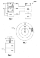
- the figure 4 illustrates a third embodiment of a human / machine interface system MMIS3 according to the invention (the reference area and the probes are not illustrated).
- the MMIS3 system comprises two integrators IT1, IT2, a phase difference detection module PDM1, a microprocessor MP, and a memory MEM.
- Each integrator IT1, IT2 comprises for example a diode, a resistor, a capacitor and a connection to ground.
- the integrators IT1, IT2 receive alternating detection signals (AC signals) S1, S2 of the probes P1, P2 and convert them into demodulated DC voltages (DC voltages) V (S1) and V (S2), the values of which depend on the amplitude of the signals S1, S2 and which are supplied to the microprocessor MP.
- AC signals alternating detection signals
- S1, S2 of the probes P1, P2 and convert them into demodulated DC voltages (DC voltages) V (S1) and V (S2), the values of which depend on the amplitude of the signals S
- the phase difference detection module PDM1 may be of analog or wired type.
- the microprocessor MP receives signals V (S1), V (S2), V ( ⁇ ) and performs the determination of the location according to at least one of the methods described above.
- the signals IS1, IS2 ... ISi are provided to external devices (not shown). In this embodiment, it is not necessary to digitize the signals S1, S2. Of course, it is possible to extend this embodiment to more than two probes by adding integrators and phase detection modules.
- the figure 5 illustrates an embodiment of the method according to the invention in which a single probe is used.
- a probe P1 is located at the center of a circular reference area RA3 with several circular and concentric locations, A01, A02, A03.
- the form The RA3 reference area circular allows, for example, several users around a table to use one H1 mobile phone one after the other to initiate various interactive actions.
- the figure 6 illustrates a probe P1 arranged on one side of a reference area RA4, which comprises several locations, for example A01, A02, A03 or more.
- the amplitude of the detected signal decreases as the portable device is moved away from the probe.
- the NFC portable devices are equipped with an NFC reader which emits a magnetic field and which can be detected by magnetic field probes, for example probes comprising detection antenna coils, Hall effect sensors etc.
- the location determining device LDD1, LDD2 performs further calculations to determine, based on the changes in locations of the portable device, the speed of movement, as well as the variations. speed (ie acceleration and deceleration). Actions are associated with a speed variation greater than a first threshold and / or less than a second threshold. For example, slowly moving the portable device to the P1 probe can move to the next slide of a visual presentation, while quickly move the portable device to the P1 probe can go directly to the end of the visual presentation.
- the portable device can also be an electronic token comprising a power source and for emitting an electric field, a field magnetic, or both.
- location may have different meanings depending on the embodiment of the invention, and that the term “area” should not be construed as being specifically limited to a one-dimensional space or two-dimensional.
- motion detection of the portable device may extend along axes that are perpendicular to the work surface, thereby defining a three-dimensional reference space.
- a mobile phone and an NFC device can be used within a single detection area, provided they do not operate exactly on the same frequency or that fields of different types are used to differentiate them, for example the electric field emitted by a mobile phone and the magnetic field emitted by an NFC mobile phone or an NFC device.
- the sets of values for the mobile phone are programmed to execute a certain set of interactive actions, while the sets of values for the phone or the NFC device are configured to perform a different set of interactive actions.
Abstract
Description
L'invention concerne un procédé de détection de l'emplacement d'un objet à l'intérieur d'une aire de référence. Plus particulièrement, l'invention concerne un procédé de localisation d'un dispositif portable émettant un champ électrique et/ou un champ magnétique à l'intérieur d'une aire de référence.The invention relates to a method for detecting the location of an object within a reference area. More particularly, the invention relates to a method for locating a portable device emitting an electric field and / or a magnetic field within a reference area.
Récemment, un intérêt grandissant est apparu pour les techniques permettant de localiser des objets au sein d'une aire de référence, afin de créer des interfaces homme/machine. Un exemple simple d'une interface homme/machine, et l'un des plus couramment utilisé, est la souris d'un ordinateur.Recently, there has been growing interest in techniques for locating objects within a reference area to create human-machine interfaces. A simple example of a human / machine interface, and one of the most commonly used, is the mouse of a computer.
Microsoft Surface® est une interface homme/machine innovante qui a été récemment présentée et qui est décrite dans la demande de brevet américaine N°
Les technologies sans fil et sans contact devenant de plus en plus omniprésentes, les utilisateurs sont de plus en plus nombreux à être équipés de dispositifs portables tels que des téléphones mobiles, des assistants numériques personnels (PDA) ou équivalent, qui émettent des champs magnétiques ou électriques radiofréquence (RF) ou ultra-haute fréquence (UHF). Par exemple, les dispositifs NFC (Near Field Communication) tels que les PDA NFC ou les téléphones portables NFC comprennent un lecteur NFC qui émet un champ magnétique RF oscillant par exemple à 13,56 MHz. De plus, classiquement, les téléphones portables émettent également un champ électromagnétique UHF ayant une composante de champ électrique afin de communiquer avec un réseau de téléphonie mobile.As wireless and contactless technologies become more and more ubiquitous, more and more users are being equipped with portable devices such as mobile phones, personal digital assistants (PDAs) or the like, which emit magnetic fields or Electric Radio Frequency (RF) or Ultra-High Frequency (UHF). For example, Near Field Communication (NFC) devices such as NFC PDAs or NFC mobile phones include an NFC reader that emits an RF magnetic field oscillating for example at 13.56 MHz. In addition, conventionally, mobile phones also emit a UHF electromagnetic field having an electric field component to communicate with a mobile telephone network.
Des modes de réalisation de l'invention comprennent l'observation selon laquelle les champs électriques ou les champs magnétiques émis par de tels dispositifs portables peuvent être utilisés pour détecter leur emplacement ou leur déplacement à l'intérieur d'une aire de référence.Embodiments of the invention include the observation that electric fields or magnetic fields emitted by such portable devices can be used to detect their location or displacement within a reference area.
Des modes de réalisation de l'invention comprennent également l'observation selon laquelle les dispositifs portables émettant un champ électrique ou un champ magnétique peuvent être utilisés comme de nouveaux types d'interfaces homme/machine afin d'initier des opérations interactives en fonction de leur emplacement à l'intérieur d'une aire de référence..Embodiments of the invention also include the observation that portable devices emitting an electric field or a magnetic field can be used as new types of human / machine interfaces to initiate interactive operations according to their location within a reference area.
Plus particulièrement, des modes de réalisation de l'invention concernent un procédé de localisation d'un dispositif portable émetteur émettant un champ électrique et/ou un champ magnétique, tel qu'un téléphone portable émettant un champ électrique ou un dispositif NFC émettant un champ magnétique, le procédé comprenant les étapes consistant à : définir une aire de référence, disposer au moins une sonde de champ électrique et/ou de champ magnétique à proximité ou à l'intérieur de l'aire de référence, disposer le dispositif portable à l'intérieur de l'aire de référence, recevoir de la sonde un signal de détection du champ électrique et/ou du champ magnétique émis par le dispositif portable, et analyser le signal de détection fourni par la sonde et en déduire l'emplacement du dispositif portable à l'intérieur de l'aire de référence.More particularly, embodiments of the invention relate to a method for locating a portable emitting device emitting an electric field and / or a magnetic field, such as a mobile phone emitting an electric field or an NFC device emitting a field. magnetic method, the method comprising the steps of: defining a reference area, having at least one electric field and / or magnetic field probe near or within the reference area, arranging the portable device to inside the reference area, receiving from the probe a detection signal of the electric field and / or the magnetic field emitted by the portable device, and analyzing the detection signal provided by the probe and deducing the location of the device portable within the reference area.
Selon un mode de réalisation, l'analyse du signal de détection comprend les étapes consistant à analyser l'amplitude du signal de détection afin de fournir une valeur d'amplitude, et à déterminer à partir de la valeur d'amplitude l'emplacement du dispositif portable à l'intérieur de l'aire de référence.According to one embodiment, the analysis of the detection signal comprises the steps of analyzing the amplitude of the detection signal to provide an amplitude value, and determining from the amplitude value the location of the detection signal. portable device within the reference area.
Selon un mode de réalisation, l'analyse du signal de détection comprend les étapes consistant à analyser la phase du signal de détection afin de fournir une valeur de phase, et à déterminer à partir de la valeur de phase l'emplacement du dispositif portable à l'intérieur de l'aire de référence.According to one embodiment, the analysis of the detection signal comprises the steps of analyzing the phase of the detection signal to provide a phase value, and determining from the phase value the location of the portable device to inside the reference area.
Selon un mode de réalisation, le procédé comprend les étapes consistant à : disposer au moins deux sondes de champ électrique et/ou de champ magnétique à proximité ou à l'intérieur de l'aire de référence, recevoir des sondes au moins deux signaux de détection et déterminer l'emplacement du dispositif portable à l'intérieur de l'aire de référence à partir de la différence de phase entre les signaux de détection.According to one embodiment, the method comprises the steps of: disposing at least two electric field and / or magnetic field probes near or within the reference area, receiving probes at least two signals of detecting and determining the location of the portable device within the reference area from the phase difference between the detection signals.
Selon un mode de réalisation, le procédé comprend les étapes consistant à : disposer au moins deux sondes de champ électrique et/ou de champ magnétique à proximité ou à l'intérieur de l'aire de référence, recevoir des sondes au moins deux signaux de détection et déterminer l'emplacement du dispositif portable à l'intérieur de l'aire de référence à partir des amplitudes des signaux de détection.According to one embodiment, the method comprises the steps of: disposing at least two electric field and / or magnetic field probes near or within the reference area, receiving probes at least two signals of detecting and determining the location of the portable device within the reference area from the amplitudes of the detection signals.
Selon un mode de réalisation, le procédé comprend les étapes consistant à : disposer au moins trois sondes de champ électrique et/ou de champ magnétique à proximité ou à l'intérieur de l'aire de référence, recevoir des sondes au moins trois signaux de détection, déterminer une première différence de phase entre une première paire de signaux de détection, déterminer au moins une seconde différence de phase entre une seconde paire de signaux de détection, et déterminer l'emplacement du dispositif portable à l'intérieur de l'aire de référence à partir des première et seconde différences de phase.According to one embodiment, the method comprises the steps of: arranging at least three electric field and / or magnetic field probes near or within the reference area, receiving probes at least three signals of detecting, determining a first phase difference between a first pair of detection signals, determining at least a second phase difference between a second pair of detection signals, and determining the location of the portable device within the area reference from the first and second phase differences.
Selon un mode de réalisation, le procédé comprend les étapes consistant à : définir des emplacements prédéterminés à l'intérieur de l'aire de référence, analyser le signal de détection fourni par la sonde, et en déduire sur quel emplacement prédéterminé est situé le dispositif portable.According to one embodiment, the method comprises the steps of: defining predetermined locations within the reference area, analyzing the detection signal provided by the probe, and deriving on which predetermined location the device is located portable.
Des modes de réalisation de l'invention concernent également un procédé permettant d'exécuter au moins une action interactive, comprenant une étape de localisation d'un dispositif portable. émetteur à l'intérieur d'une aire de référence selon le procédé décrit ci-dessus, et une étape d'initiation de l'action interactive en fonction de l'emplacement du dispositif portable à l'intérieur de l'aire de référence.Embodiments of the invention also relate to a method for performing at least one interactive action, comprising a step of locating a portable device. transmitter within a reference area according to the method described above, and a step of initiating the interactive action according to the location of the portable device within the reference area.
Selon un mode de réalisation, l'initiation de l'action interactive comprend une étape consistant à fournir des signaux de contrôle interactifs à un dispositif externe configuré pour effectuer l'action interactive.According to one embodiment, the initiation of the interactive action includes a step of providing interactive control signals to an external device configured to perform the interactive action.
Des modes de réalisation de l'invention concernent également un système d'interface homme/machine à utiliser avec un dispositif portable émettant un champ électrique et/ou un champ magnétique, tel qu'un téléphone portable émettant un champ électrique ou un dispositif NFC émettant un champ magnétique, et comprenant au moins une sonde de champ électrique et/ou de champ magnétique fournissant un signal de détection, un dispositif de détermination d'emplacement, le dispositif de détermination d'emplacement étant configuré pour analyser le signal de détection, en déduire l'emplacement du dispositif portable à l'intérieur d'une aire de référence, et initier au moins une action interactive en fonction de l'emplacement du dispositif portable.Embodiments of the invention also relate to a human / machine interface system for use with a portable device emitting an electric field and / or a magnetic field, such as a mobile phone emitting an electric field or an NFC device emitting a magnetic field, and comprising at least one electric field and / or magnetic field probe providing a detection signal, a location determining device, the location determining device being configured to analyze the detection signal, in deriving the location of the portable device within a reference area, and initiating at least one interactive action depending on the location of the portable device.
Selon un mode de réalisation, le dispositif de détermination d'emplacement est configuré pour déterminer l'emplacement du dispositif portable à partir de la valeur d'amplitude du signal de détection.According to one embodiment, the location determining device is configured to determine the location of the portable device from the amplitude value of the detection signal.
Selon un mode de réalisation, le dispositif de détermination d'emplacement est configuré pour déterminer l'emplacement du dispositif portable à partir de la valeur de phase du signal de détection.According to one embodiment, the location determining device is configured to determine the location of the portable device from the phase value of the detection signal.
Selon un mode de réalisation, le système comprend au moins deux sondes de champ électrique et/ou de champ magnétique à proximité ou à l'intérieur de l'aire de référence, fournissant des signaux de détection, et le dispositif de détermination d'emplacement est configuré pour déterminer l'emplacement du dispositif portable à l'intérieur de l'aire de référence à partir de la différence de phase entre les signaux de détection.According to one embodiment, the system comprises at least two electric field and / or magnetic field probes near or within the reference area, providing detection signals, and the location determining device is configured to determine the location of the portable device within the reference area from the phase difference between the detection signals.
Selon un mode de réalisation, le système comprend au moins deux sondes de champ électrique et/ou de champ magnétique à proximité ou à l'intérieur de l'aire de référence, fournissant des signaux de détection, et le dispositif de détermination d'emplacement est configuré pour déterminer l'emplacement du dispositif portable à l'intérieur de l'aire de référence à partir des amplitudes des signaux de détection.According to one embodiment, the system comprises at least two electric field and / or magnetic field probes near or within the reference area, providing detection signals, and the location determining device is configured to determine the location of the device portable within the reference area from the amplitudes of the detection signals.
Selon un mode de réalisation, le système comprend au moins trois sondes de champ électrique et/ou de champ magnétique à proximité ou à l'intérieur de l'aire de référence, les sondes fournissant des signaux de détection, et le dispositif de détermination d'emplacement est configuré pour déterminer une première différence de phase entre une première paire de signaux de détection, déterminer au moins une seconde différence de phase entre une seconde paire de signaux de détection, et déterminer l'emplacement du dispositif portable à l'intérieur de l'aire de référence à partir des première et seconde différences de phase.According to one embodiment, the system comprises at least three electric field and / or magnetic field probes near or within the reference area, the probes providing detection signals, and the device for determining the detection field. location is configured to determine a first phase difference between a first pair of sense signals, determine at least a second phase difference between a second pair of sense signals, and determine the location of the portable device within a second pair of sense signals; the reference area from the first and second phase differences.
Selon un mode de réalisation, le dispositif de détermination d'emplacement est configuré pour mémoriser des emplacements prédéterminés à l'intérieur de l'aire de référence, associer au moins une action interactive à chaque emplacement prédéterminé du dispositif portable, déterminer à partir du signal de détection sur quel emplacement prédéterminé est situé le dispositif portable, et initier l'action interactive qui est associée à l'emplacement du dispositif portable.According to one embodiment, the location determining device is configured to store predetermined locations within the reference area, associating at least one interactive action at each predetermined location of the portable device, determining from the signal sensing on which predetermined location is located the portable device, and initiating the interactive action that is associated with the location of the portable device.
Selon un mode de réalisation, le dispositif de détermination d'emplacement est configuré pour enregistrer, pour chaque emplacement prédéterminé, d'un ensemble de valeurs d'amplitude et/ou de phase des signaux de détection lorsque le dispositif portable est placé sur l'emplacement.According to one embodiment, the location determining device is configured to record, for each predetermined location, a set of amplitude and / or phase values of the detection signals when the portable device is placed on the location.
Des modes de réalisation d'un procédé de localisation d'un dispositif portable émetteur selon l'invention et d'un système d'interface homme/machine selon l'invention seront exposés dans la description suivante faite à titre non limitatif en relation avec les figures jointes parmi lesquelles :
- la
figure 1 illustre un premier mode de réalisation du procédé et du système d'interface homme/machine, - les
figures 2A ,2B, 2C illustrent un second mode de réalisation du procédé, - la
figure 3 illustre un second mode de réalisation du système d'interface homme/machine, - la
figure 4 illustre un troisième mode de réalisation du système d'interface homme/machine, - la
figure 5 illustre un troisième mode de réalisation du procédé, et - la
figure 6 illustre un quatrième mode de réalisation du procédé.
- the
figure 1 illustrates a first embodiment of the method and the human / machine interface system, - the
Figures 2A ,2B, 2C illustrate a second embodiment of the method, - the
figure 3 illustrates a second embodiment of the human / machine interface system, - the
figure 4 illustrates a third embodiment of the man / machine interface system, - the
figure 5 illustrates a third embodiment of the method, and - the
figure 6 illustrates a fourth embodiment of the method.
Des modes de réalisation d'un procédé de localisation d'un dispositif portable émetteur selon l'invention comprennent les étapes consistant à définir une aire de référence et à agencer des sondes de champ électrique et/ou de champ magnétique autour de l'aire de référence. Un dispositif portable émettant un champ électrique et/ou un champ magnétique est placé à l'intérieur de l'aire de référence, et les sondes fournissent des signaux de détection. Chaque signal de détection est l'image du champ électrique ou magnétique émis par le dispositif portable tel que détecté par la sonde considérée, et son amplitude et sa phase dépendent de la distance entre le dispositif portable et la sonde. Les signaux de détection sont utilisés pour déterminer l'emplacement du dispositif portable.Embodiments of a method for locating a portable transmitting device according to the invention include the steps of defining a reference area and arranging electric field and / or magnetic field probes around the area of the invention. reference. A portable device emitting an electric field and / or a magnetic field is placed inside the reference area, and the probes provide detection signals. Each detection signal is the image of the electric or magnetic field emitted by the portable device as detected by the probe in question, and its amplitude and its phase depend on the distance between the portable device and the probe. The detection signals are used to determine the location of the portable device.
Le système d'interface homme/machine reçoit des signaux de détection fournis par les sondes et évalue l'emplacement du dispositif portable à l'intérieur de l'aire de référence. Des opérations peuvent être assignées aux divers emplacements sur l'aire de référence, et sont exécutées lorsqu'un utilisateur place le dispositif portable à un certain emplacement.The human-machine interface system receives detection signals provided by the probes and evaluates the location of the portable device within the the reference area. Operations may be assigned to the various locations on the reference area, and are executed when a user places the portable device at a certain location.
Un premier mode de réalisation du procédé est illustré sur la
Dans ce mode de réalisation, l'aire de référence RA1 est sensiblement un espace unidimensionnel selon un axe X selon lequel les sondes P1, P2 sont agencées. L'aire de référence peut être considérée comme une ligne confondue avec l'axe X, ou un rectangle fin aligné sur l'axe X, présentant une petite largeur et une longueur égale à la distance entre les sondes P1, P2.In this embodiment, the reference area RA1 is substantially a one-dimensional space along an axis X in which the probes P1, P2 are arranged. The reference area may be considered as a line coinciding with the X axis, or a fine rectangle aligned with the X axis, having a small width and a length equal to the distance between the probes P1, P2.
Les sondes P1, P2 illustrées sur la
Les sondes P1, P2 sont séparées l'une de l'autre par une distance connue D12. Lorsque le dispositif portable H1 est placé sur l'aire de référence RA1, les sondes P1, P2 détectent le champ électrique émis par le dispositif portable et fournissent des signaux de détection S1, S2.Probes P1, P2 are separated from each other by a known distance D12. When the portable device H1 is placed on the reference area RA1, the probes P1, P2 detect the electric field emitted by the portable device and provide detection signals S1, S2.
Le fait de connaître la distance D12 permet de déterminer l'emplacement du dispositif portable sur l'axe X sans nécessiter d'étape d'étalonnage. L'emplacement du dispositif portable H1 peut être déterminé au moyen de la différence de phase entre les signaux S1, S2 ou la différence d'amplitude entre les signaux S1, S2, comme cela sera expliqué plus loin.Knowing the distance D12 makes it possible to determine the location of the portable device on the X axis without requiring a calibration step. The location of the portable device H1 can be determined by means of the phase difference between the signals S1, S2 or the difference in amplitude between the signals S1, S2, as will be explained later.
Localisation du dispositif portable émetteur au moyen de la différence de phase entre S1, S2Location of the portable transmitter device by means of the phase difference between S1, S2
Puisque l'aire de référence est ici sensiblement une ligne ou un rectangle fin, la distance D12 peut être considérée comme la somme d'une distance D1 entre la sonde P1 et le dispositif portable H1, et une distance D2 entre 1a sonde P2 et le dispositif portable. Par conséquent, il peut être écrit : 
Pour déterminer l'emplacement du dispositif portable à l'intérieur de l'aire de référence, D1 et D2 doivent être déterminés. Le signal électromagnétique émis par le dispositif portable H1 se déplace à la vitesse de la lumière, et 1a phase des signaux S1, S2 fournis par les sondes P1, P2 dépendent de D1 et D2 : ![]()
![]()
![]()
![]()
Il est supposé que les valeurs absolues des phases ϕ1, ϕ2 ne peuvent être mesurées puisque la phase à l'origine de l'onde émise (c'est-à-dire la phase de l'emplacement du dispositif portable) n'est pas connue. Cependant, la différence de phase Δϕ=ϕ1-ϕ2 peut être mesurée et permet de déterminer D1 et D2. En fait, si la distance D12 entre la sonde est inférieure ou égale à la longueur d'onde λ, les équations 2a et 2b ne sont plus modulo 2π et peuvent être écrites ainsi : ![]()
![]()
![]()
![]()
En combinant les équations 2a' et 2b', on obtient : 
avec K1=λ/2π et Δϕ=ϕ1-ϕ2By combining equations 2a 'and 2b', we obtain:
with K1 = λ / 2π and Δφ = φ1-φ2
En combinant les équations 1 et 3, on obtient : ![]()

![]()
Puisque K1 est connu et que Δϕ peut être mesuré grâce aux sondes P1, P2, D1 et D2 peuvent être déterminées au moyen des équations 4 et 5.Since K1 is known and Δφ can be measured using probes P1, P2, D1 and D2 can be determined using
Localisation du dispositif portable émetteur au moyen de l'amplitude de S1, S2Location of the portable transmitter device by means of the amplitude of S1, S2
Alternativement, l'amplitude des signaux détectés par les sondes est utilisée pour déterminer l'emplacement du dispositif portable. La sonde P1 détecte un signal d'amplitude M1 et la sonde P2 détecte un signal d'amplitude M2. Dans une approximation simplificatrice, il est supposé que l'amplitude décroît proportionnellement à la distance par rapport au dispositif portable émetteur et que la relation entre l'amplitude et la distance est une fonction affine F (c'est-à-dire une fonction linéaire avec une translation) du type « -ax+b » avec une pente négative. Par conséquent, il peut être écrit : ![]()
![]()
![]()
![]()
M0 étant l'amplitude maximale détectée lorsque la distance entre les sondes et l'objet émetteur est nulle, K2 étant une constante représentant la pente de la fonction F qui est déterminée au moyen d'une étape d'étalonnage.M0 being the maximum amplitude detected when the distance between the probes and the emitter object is zero, K2 being a constant representing the slope of the function F which is determined by means of a calibration step.
En combinant les équations 6a et 6b, on obtient : 
Puis, en combinant l'équation 7 et l'équation 1, on obtient : ![]()
ou : 


![]()
or :
Puisque K2 est connu et que M1-M2 peut être mesuré grâce aux sondes P1, P2, D1 et D2 peuvent être déterminés au moyen des équations 10 et 11.Since K2 is known and M1-M2 can be measured by probes P1, P2, D1 and D2 can be determined using equations 10 and 11.
Alternativement, l'étape d'étalonnage servant à déterminer la pente de K2 est remplacée par une étape d'étalonnage plus simple visant à déterminer seulement la valeur de l'amplitude M0 à proximité des sondes P1, P2. Dans ce cas, les équations 6a, 6b peuvent être écrites ainsi : ![]()
![]()
et combinées par division afin d'obtenir : 
![]()
![]()
and combined by division to obtain:
En nommant « P » la valeur « (M2-M0) / (M1-M0) », on obtient les équations alternatives 10', 11' suivantes : ![]()
![]()
![]()
![]()
Puisqu'il est possible de déterminer M0 grâce à une étape d'étalonnage et de mesurer M1, M2 grâce aux sondes P1, P2, D1 et D2 peuvent être déterminés au moyen des équations 10' et 11'.Since it is possible to determine M0 through a calibration step and measure M1, M2 through probes P1, P2, D1 and D2 can be determined using equations 10 'and 11'.
La
Le dispositif LDD1 peut optionnellement être équipé d'une unité d'affichage DU. Le convertisseur analogique-numérique ADC1 peut également faire partie du dispositif LDD1. Dans un mode de réalisation, le dispositif LDD1 est un ordinateur personnel, le dispositif de stockage SD est un disque dur et l'unité d'affichage DU est un moniteur. Le moniteur peut avoir comme interface un écran tactile et/ou l'ordinateur personnel peut également être équipé d'un organe d'entrée tel qu'un clavier (non illustré).The device LDD1 may optionally be equipped with a display unit DU. The analog-digital converter ADC1 can also be part of the LDD1 device. In one embodiment, the LDD1 device is a personal computer, the SD storage device is a hard disk and the display unit DU is a monitor. The monitor can have as interface a touch screen and / or the personal computer may also be equipped with an input member such as a keyboard (not shown).
Une fois que l'emplacement du dispositif portable a été calculé, le dispositif LDD1 fournit des signaux de contrôle interactifs IS1, IS2...ISi en fonction d'actions assignées aux divers emplacements du dispositif portable. Ces signaux de contrôle sont utilisés pour initier des opérations comme « Allumer la lumière », « Eteindre la lumière », « Allumer la télévision », « Eteindre la télévision », « Allumer la radio », « Eteindre la radio », « Diapositive suivante », « Diapositive précédente » (pour un système de projection d'image lors d'une présentation) etc. Ces opérations sont des actions définies par l'utilisateur, un administrateur, ou par le fabricant ou le fournisseur du système.Once the location of the portable device has been calculated, the device LDD1 provides interactive control signals IS1, IS2 ... ISi based on actions assigned to the various locations of the portable device. These control signals are used to initiate operations such as "Turn on the light", "Turn off the light", "Turn on the television", "Turn off the television", "Turn on the radio", "Turn off the radio", "Next slide" »,« Previous slide »(for an image projection system during a presentation) etc. These operations are actions defined by the user, an administrator, or by the manufacturer or system vendor.
Une étape préliminaire peut être effectuée avant que le système soit utilisé afin de définir les actions à exécuter lorsque le dispositif portable H1 est détecté dans les divers emplacements de l'aire de référence. Elle peut consister à choisir des actions à partir d'un menu prédéfini. Par exemple, l'aire de référence pourrait être divisée en plusieurs zones différentes (non illustrées), comme une zone Z1 à proximité de la sonde P1, une zone Z2 au centre, et une zone Z3 à proximité de la sonde P2.A preliminary step may be performed before the system is used to define the actions to be performed when the portable device H1 is detected in the various locations of the reference area. It can consist of choosing actions from a predefined menu. For example, the reference area could be divided into several different zones (not shown), such as a zone Z1 near the probe P1, a zone Z2 in the center, and a zone Z3 near the probe P2.
Pour faciliter l'utilisation du dispositif, chaque emplacement peut également être marqué par des symboles, des photos, des mots, etc. afin d'indiquer à l'utilisateur où placer le dispositif portable pour qu'une action soit exécutée. Des modèles préconfigurés, par exemple une icône représentant une ampoule pour indiquer que la lumière va s'allumer, peuvent être fournis. De plus, ces modèles, qui peuvent également indiquer où placer les sondes, peuvent varier en fonction du type de dispositif portable à utiliser, le nombre de sondes, la taille et la forme de l'aire de référence, etc.To facilitate the use of the device, each location can also be marked with symbols, photos, words, etc. to indicate to the user where to place the portable device for an action to be performed. Preconfigured templates, for example an icon representing a light bulb to indicate that the light will turn on, can be provided. In addition, these models, which may also indicate where to place the probes, may vary depending on the type of portable device to be used, the number of probes, the size and shape of the reference area, etc.
Un autre exemple d'utilisation consiste à connecter le système d'interface home/machine à un système audio ou à la lumière, et à utiliser le mouvement du dispositif portable comme un interrupteur coulissant pour augmenter ou diminuer le volume ou l'intensité de la lumière. Le système MMIS1 est configuré de telle sorte qu'au fur et à mesure que le dispositif portable est déplacé vers la sonde P1, l'amplitude M1 augmente alors que l'amplitude M2 diminue et le volume ou l'intensité de la lumière augmente. Inversement, au fur et à mesure que le dispositif portable est déplacé vers la sonde P2, l'amplitude M2 augmente alors que l'amplitude M1 diminue, et le volume ou l'intensité de la lumière diminue.Another example of use is to connect the home / machine interface system to an audio system or to light, and to use the movement of the portable device as a sliding switch to increase or decrease the volume or intensity of the light. The system MMIS1 is configured so that as the portable device is moved to the probe P1, the amplitude M1 increases as the amplitude M2 decreases and the volume or intensity of the light increases. Conversely, as the portable device is moved to the probe P2, the amplitude M2 increases as the amplitude M1 decreases, and the volume or intensity of the light decreases.
Dans d'autres modes de réalisation, les sondes P1, P2 peuvent également être des sondes de champ magnétique, par exemple des bobines d'antenne configurées pour détecter un champ magnétique émis par un dispositif portable comprenant un contrôleur NFC (Near Field Communication). Par exemple, avec un champ magnétique de 13,56 MHz émis par un téléphone portable NFC conforme à la norme ISO 14443 ou ISO 15693, la longueur d'onde λ est égale à 22,1 m et représente la distance maximale entre les sondes P1, P2 si la méthode de différence de phase est utilisée pour localiser le dispositif portable.In other embodiments, the probes P1, P2 may also be magnetic field probes, for example antenna coils configured to detect a magnetic field emitted by a portable device comprising a NFC (Near Field Communication) controller. For example, with a magnetic field of 13.56 MHz emitted by an NFC mobile phone complying with the ISO 14443 or ISO 15693 standard, the wavelength λ is equal to 22.1 m and represents the maximum distance between the P1 probes. , P2 if the phase difference method is used to locate the portable device.
Un second mode de réalisation d'un procédé de localisation d'un dispositif portable émetteur à l'intérieur d'une aire de référence est illustré sur la
Le dispositif portable H1 est ensuite agencé à l'intérieur de l'aire de référence RA2, en un point E1. Les sondes P1, P2, P3, P4 détectent le champ électrique ou le champ magnétique émis par le dispositif portable et fournissent des signaux de détection S1, S2, S3, S4.The portable device H1 is then arranged inside the reference area RA2 at a point E1. The probes P1, P2, P3, P4 detect the electric field or the magnetic field emitted by the portable device and provide detection signals S1, S2, S3, S4.
Le fait de connaître les emplacements F1, F2, F3, F4 dans le système de coordonnées Oxy permet de déterminer l'emplacement du dispositif portable à l'intérieur de l'aire de référence RA2 sans nécessiter une étape d'étalonnage. L'emplacement E1 du dispositif portable H1 est déterminé au moyen de la différence de phase entre les signaux S1 et S2, S3 et S4. Les phases ϕ1, ϕ2, ϕ3, ϕ4 des signaux S1, S2, S3, S4 fournis par les sondes P1, P2, P3, P4 aux points F1, F2, F3, F4 sont conformes aux équations suivantes : ![]()
![]()
![]()
![]()
dans lesquelles D1 est la distance entre E1 et F1, D2 la distance entre E1 et F2, D3 la distance entre E1 et F3 et D4 la distance entre E1 et F4. Il est de nouveau supposé que les valeurs absolues des phases ϕ1, ϕ2, ϕ3, ϕ4 ne peuvent être mesurées puisque la phase initiale de l'onde émise n'est pas connue. Cependant, il est possible de mesurer la différence de phase ϕ1-ϕ2 et ϕ3-ϕ4.Knowing the locations F1, F2, F3, F4 in the Oxy coordinate system makes it possible to determine the location of the portable device within the reference area RA2 without requiring a calibration step. The location E1 of the portable device H1 is determined by means of the phase difference between the signals S1 and S2, S3 and S4. The phases φ1, φ2, φ3, φ4 of the signals S1, S2, S3, S4 provided by the probes P1, P2, P3, P4 at the points F1, F2, F3, F4 are in accordance with the following equations: ![]()
![]()
![]()
![]()
where D1 is the distance between E1 and F1, D2 the distance between E1 and F2, D3 the distance between E1 and F3 and D4 the distance between E1 and F4. It is again assumed that the absolute values of the phases φ1, φ2, φ3, φ4 can not be measured since the initial phase of the transmitted wave is not known. However, it is possible to measure the phase difference φ1-φ2 and φ3-φ4.
Comme le dispositif portable a été placé en dehors d'une ligne passant par F1 et F2 ou en dehors d'une ligne passant par F3 et F4, la somme D1+D2 n'est plus égale à la distance entre les sondes P1, P2 et la somme D3+D4 n'est pas égale à la distance entre les sondes P3, P4. Par conséquent, la méthode proportionnelle décrite ci-dessus n'est pas appropriée pour déterminer les valeurs de D1 et D2, ou de D3 et D4. Cependant, si chaque distance D1, D2, D3, D4 est inférieure ou égale à la longueur d'onde λ, les équations 12a à 12d ne sont plus modulo 2n et peuvent être écrites ainsi : ![]()
![]()
![]()
![]()
dans lesquelles K1=λ/2π.Since the portable device has been placed outside a line passing through F1 and F2 or outside a line passing through F3 and F4, the sum D1 + D2 is no longer equal to the distance between the probes P1, P2 and the sum D3 + D4 is not equal to the distance between the probes P3, P4. Therefore, the proportional method described above is not appropriate for determining the values of D1 and D2, or D3 and D4. However, if each distance D1, D2, D3, D4 is less than or equal to the wavelength λ, the equations 12a to 12d are no longer modulo 2n and can be written as follows: ![]()
![]()
![]()
![]()
in which K1 = λ / 2π.
En combinant les équations 12a' et 12b' et en combinant les équations 12c' et 12d', on obtient : ![]()
![]()
![]()
![]()
L'équation 13a est l'équation d'une première hyperbole dont F1 et F2 sont les foyers, qui comprend une série de points situés à des distances D1 et D2 des sondes P1 et P2 et pour lesquels D1-D2=(ϕ1-ϕ2)*K1. L'hyperbole peut être tracée dans le plan Oxy tel qu'illustré sur la
De la même façon, l'équation 13b est l'équation d'une seconde hyperbole dont les foyers sont F3 et F4 et comprenant une série de points à des distances D3 et D4 des sondes P3 et P4 et pour lesquels D3-D4=(ϕ3-ϕ4)*K1. La seconde hyperbole peut également être tracée dans le plan Oxy tel qu'illustré sur la
Une fois que les hyperboles sont tracées ou que leurs points ont été simplement calculés, quatre points d'intersection E1, E1', E1", E1"' sont trouvés. Le point où se situe réellement le dispositif portable, ici le point E1, doit être choisi parmi les points E1, E1', E1", E1"'. La détermination de l'emplacement réel parmi les quatre emplacements possibles est effectuée en utilisant le signe des différences de phase ou le signe dés différences entre les amplitudes M1, M2, M3, M4 des signaux S1, S2, S3, S4 afin de déterminer dans quel quadrant du plan Oxy se situe le point d'intersection recherché, les quatre quadrants étant par exemple définis de la façon suivante : x>0 et y>0, x>0 et y<0, x<0 et y<0, x<0 et y>0.Once the hyperbolas are plotted or their points have been simply calculated, four points of intersection E1, E1 ', E1 ", E1"' are found. The point where the portable device is located, here the point E1, must be chosen from the points E1, E1 ', E1 ", E1"'. The determination of the actual location among the four possible locations is performed using the sign of the phase differences or the sign d differences between the magnitudes M1, M2, M3, M4 of the signals S1, S2, S3, S4 to determine in which quadrant of the plane Oxy is the desired intersection point, the four quadrants being for example defined as follows: x> 0 and y> 0, x> 0 and y <0, x <0 and y <0, x <0 and y> 0.
Par exemple :
- le dispositif portable est situé en E1 si ϕ1-ϕ2<0 et ϕ3-ϕ4<0 car la phase est plus petite lorsque que le dispositif portable est plus près de la sonde considérée,
- le dispositif portable est situé en E1' si ϕ1-ϕ2>0 et ϕ3-ϕ4<0,
- le dispositif portable est situé en E1" si ϕ1-ϕ2>0 et ϕ3-ϕ4>0, et
- le dispositif portable est situé en E1"' si ϕ1-ϕ2<0 et ϕ3-ϕ4>0.
- the portable device is located in E1 if φ1-φ2 <0 and φ3-φ4 <0 because the phase is smaller when the portable device is closer to the considered probe,
- the portable device is located in E1 'if φ1-φ2> 0 and φ3-φ4 <0,
- the portable device is located in E1 "if φ1-φ2> 0 and φ3-φ4> 0, and
- the portable device is located in E1 "'if φ1-φ2 <0 and φ3-φ4> 0.
En utilisant les amplitudes M1, M2, M3, M4 :
- le dispositif portable est situé en E1 si M1-M2>0 et M3-M4>0, car l'amplitude est supérieure lorsque que le dispositif portable est plus près de la sonde considérée,
- le dispositif portable est situé en E1' si M1-M2<0 et M3-M4>0,
- le dispositif portable est situé en E1" si M1-M2<0 et M3-M4<0, et
- le dispositif portable est situé en E1"' si M1-M2>0 et M3-M4<0.
- the portable device is located at E1 if M1-M2> 0 and M3-M4> 0, because the amplitude is greater when the portable device is closer to the probe considered,
- the portable device is located at E1 'if M1-M2 <0 and M3-M4> 0,
- the portable device is located in E1 "if M1-M2 <0 and M3-M4 <0, and
- the portable device is located in E1 "'if M1-M2> 0 and M3-M4 <0.
Dans un mode de réalisation, l'identification du quadrant dans lequel le dispositif portable est situé, c'est-à-dire le quadrant dans lequel le point d'intersection recherché est situé, est effectuée avant la recherche de l'intersection des hyperboles, afin de simplifier le calcul en évitant de devoir chercher les quatre points d'intersection.In one embodiment, the identification of the quadrant in which the portable device is located, i.e., the quadrant in which the desired intersection point is located, is performed prior to searching for the intersection of the hyperbolas. , in order to simplify the calculation by avoiding having to look for the four points of intersection.
A des fins d'illustration, la
Il apparaîtra clairement à l'homme de l'art que le mode de réalisation du procédé qui vient d'être décrit est susceptible de nombreux autres modes de réalisation. Par exemple, au lieu de mesurer les différences de phase ϕ1-ϕ2, ϕ3-ϕ4, le procédé peut utiliser les différences de phase ϕ1-ϕ3, ϕ2-ϕ4 et les hyperboles correspondantes et leurs points d'intersection, ou les différences de phase ϕ1-ϕ4, ϕ2-ϕ3 et les hyperboles correspondantes et leurs points d'intersection. Egalement, au lieu d'utiliser quatre sondes, il est possible de n'en utiliser que trois P1, P2, P3, et le procédé peut utiliser les différences de phase ϕ1-ϕ3, ϕ2-ϕ3 et les hyperboles correspondantes et leurs points d'intersection.It will be apparent to those skilled in the art that the embodiment of the method just described is capable of many other embodiments. For example, instead of measuring the phase differences φ1-φ2, φ3-φ4, the method can use the phase differences φ1-φ3, φ2-φ4 and the corresponding hyperbolas and their points of intersection, or the phase differences φ1-φ4, φ2-φ3 and the corresponding hyperbolas and their points of intersection. Also, instead of using four probes, it is possible to use only three P1, P2, P3, and the method can use the phase differences φ1-φ3, φ2-φ3 and the corresponding hyperbolas and their dots. 'intersection.
Il est également possible de localiser le dispositif portable au moyen d'une mesure de l'amplitude des signaux S1-S4. Comme décrit ci-dessus, il peut être écrit : ![]()
![]()
![]()
![]()
![]()
![]()
![]()
![]()
M0 étant l'amplitude maximale détectée lorsque la distance entre les sondes et l'objet émetteur est nulle, et K2 étant la pente de la fonction affine F susmentionnée. Par conséquent, il peut être écrit : ![]()
![]()
![]()
![]()
L'équation 14a est l'équation d'une première hyperbole dont les foyers sont F1 et F2 et comprenant une série de points à des distances D1 et D2 des sondes P1 et P2 et pour lesquels D1-D2=(1/K2) * (M1-M2). L'hyperbole peut être tracée dans le plan Oxy si K2 est connu (alternativement ses points peuvent calculés au moyen d'un dispositif de détermination d'emplacement). L'équation 14b est l'équation d'une seconde hyperbole dont les foyers sont F3 et F4 et comprenant une série de points à des distances D3 et D4 des sondes P3 et P4 et pour lesquels D3-D4=(1/K2)*(M3-M4). La seconde hyperbole peut également être tracée dans le plan Oxy, ou ses points être simplement calculés. Une fois que les hyperboles sont tracées ou que leurs points sont simplement calculés, quatre points d'intersection E1, E1', E1", E1"' sont trouvés, comme précédemment. Le point où est réellement situé le dispositif portable, ici le point E1, doit être choisi parmi les points E1, E1', E1", E1"'. La détermination de l'emplacement réel entre les quatre emplacements possibles est effectuée en utilisant le signe des différences entre les amplitudes M1, M2, M3, M4 des signaux S1, S2, S3, S4 pour déterminer dans quel quadrant du plan Oxy est situé le point d'intersection recherché, ou le signe des différences de phase. Le quadrant peut également être déterminé avant le calcul des hyperboles, afin de réduire le nombre de points des hyperboles à calculer.Equation 14a is the equation of a first hyperbola whose foci are F1 and F2 and comprising a series of points at distances D1 and D2 of the probes P1 and P2 and for which D1-D2 = (1 / K2) * (M1-M2). The hyperbola can be plotted in the Oxy plane if K2 is known (alternatively its points can be calculated by means of a location determination device). Equation 14b is the equation of a second hyperbola whose foci are F3 and F4 and comprising a series of points at distances D3 and D4 of probes P3 and P4 and for which D3-D4 = (1 / K2) * (M3-M4). The second hyperbola can also be plotted in the Oxy plane, where its points are simply calculated. Once the hyperbolas are drawn or their points are simply calculated, four points of intersection E1, E1 ', E1 ", E1"' are found, as before. The point where the portable device is actually located, here the point E1, must be chosen from the points E1, E1 ', E1 ", E1"'. The determination of the actual location between the four possible locations is made by using the sign of the differences between the amplitudes M1, M2, M3, M4 of the signals S1, S2, S3, S4 to determine in which quadrant of the plane Oxy is located the desired intersection point, or the sign of phase differences. The quadrant can also be determined before calculating the hyperbolas, in order to reduce the number of hyperbola points to calculate.
La
Tout comme le système MMIS1 précédemment décrit, le système MMIS2 comprend un convertisseur analogique-numérique ADC2, un dispositif de détermination d'emplacement LDD2 et en option, une unité de stockage SD et une unité d'affichage DU.Like the previously described MMIS1 system, the MMIS2 system includes an ADC2 analog-to-digital converter, an LDD2 location determiner, and an optional SD storage unit and a DU display unit.
Lorsque le dispositif portable H1 est placé sur l'aire de référence RA2, les sondes P1-P4 fournissent des signaux de détection S1-S4, respectivement. Les signaux de détection sont numérisés par le convertisseur ADC2, qui fournit ensuite les signaux numérisés DS1'-DS4' au dispositif LDD2. Le dispositif LDD2 effectue les étapes suivantes :
- mesurer ϕ1-ϕ2,
- mesurer ϕ3-ϕ4,
- mesurer M1-M2 (optionnel),
- mesurer M3-M4 (optionnel),
- trouver les points d'intersection E1, E1', E1", E1"' des hyperboles H12, H12' et H34, H34' définies par les équations 13a et 13b, et
- déterminer l'emplacement réel du dispositif portable parmi les quatre points d'intersection en utilisant le signe des différences de phase ϕ1-ϕ2, ϕ3-ϕ4 et/ou en utilisant le signe des différences d'amplitude M1-M2, M3-M4.
- measure φ1-φ2,
- measure φ3-φ4,
- measure M1-M2 (optional),
- measure M3-M4 (optional),
- find the points of intersection E1, E1 ', E1 ", E1"' of hyperbolas H12, H12 'and H34, H34' defined by equations 13a and 13b, and
- determining the actual location of the portable device among the four intersection points using the sign of the phase differences φ1-φ2, φ3-φ4 and / or using the sign of amplitude differences M1-M2, M3-M4.
Selon la variante décrite ci-dessus, le dispositif LDD2 peut également d'abord rechercher le quadrant dans lequel le dispositif portable est situé, puis seulement rechercher le(s) point(s) d'intersection des hyperboles qui se situent dans ce quadrant.According to the variant described above, the device LDD2 can also first look for the quadrant in which the portable device is located, then only find the point (s) of intersection of the hyperbolas that are in this quadrant.
Une fois que l'emplacement du dispositif portable a été calculé, le dispositif LDD2 fournit des signaux de contrôle interactifs IS1, IS2...ISi en fonction d'actions assignées aux divers emplacements du dispositif portable. Les signaux de contrôle sont utilisés pour initier des opérations (voir les exemples décrits ci-dessus).Once the location of the portable device has been calculated, the device LDD2 provides interactive control signals IS1, IS2 ... ISi based on actions assigned to the various locations of the portable device. The control signals are used to initiate operations (see the examples described above).
Une étape préliminaire peut être effectuée avant que le système soit utilisé afin de définir les actions à exécuter lorsque le dispositif portable H1 est détecté dans les divers emplacements de l'aire de référence. Cette étape peut consister à choisir des actions à partir d'un menu prédéfini. Par exemple, l'aire de référence pourrait être divisée en plusieurs zones différentes (non illustrées), par exemple dix zones différentes Z1 à Z10, chacune étant assignée à une action spécifique.A preliminary step may be performed before the system is used to define the actions to be performed when the portable device H1 is detected in the various locations of the reference area. This step may consist of choosing actions from a predefined menu. For example, the reference area could be divided into several different zones (not shown), for example ten different zones Z1 to Z10, each being assigned to a specific action.
Comme indiqué ci-dessus, au lieu de mesurer les différences de phase ϕ1-ϕ2, ϕ3-ϕ4, le système MMIS2 peut mesurer les différences de phase ϕ1-ϕ3, ϕ2-ϕ4 et déterminer les points d'intersection des hyperboles correspondantes, ou mesurer les différences de phase ϕ1-ϕ4, ϕ2-ϕ3 et déterminer les points d'intersection des hyperboles correspondantes. Egalement, au lieu de comprendre quatre sondes, le système MMIS2 peut comprendre seulement trois sondes P1, P2, P3, et peut être configuré pour mesurer les différences de phase ϕ1-ϕ3, ϕ2-ϕ3 et déterminer les points d'intersection des hyperboles correspondantes. Le système MMIS2 peut également comprendre plus de quatre sondes, par exemple dix sondes agencées en divers emplacements à proximité des limites de l'aire de référence.As indicated above, instead of measuring the phase differences φ1-φ2, φ3-φ4, the MMIS2 system can measure the phase differences φ1-φ3, φ2-φ4 and determine the points of intersection of the corresponding hyperbolas, or measure the phase differences φ1-φ4, φ2-φ3 and determine the points of intersection of the corresponding hyperbolas. Also, instead of including four probes, the MMIS2 system can comprise only three probes P1, P2, P3, and can be configured to measure the phase differences φ1-φ3, φ2-φ3 and determine the points of intersection of the corresponding hyperbolas. . The MMIS2 system can also include more than four probes, for example ten probes arranged at various locations near the boundaries of the reference area.
Dans un autre mode de réalisation, le dispositif LDD2 effectue les étapes suivantes :
- mesurer K2 (étape d'étalonnage),
- mesurer M1,
- mesurer M2,
- mesurer M3,
- mesurer M4,
- trouver les points d'intersection E1, E1', E1", E1"' des hyperboles définies par les équations 14a et 14b, et
- déterminer l'emplacement réel du dispositif portable parmi les quatre points d'intersection en utilisant le signe des différences d'amplitude M1-M2, M3-M4.
- measure K2 (calibration step),
- measure M1,
- measure M2,
- measure M3,
- measure M4,
- find the points of intersection E1, E1 ', E1 ", E1"' of the hyperbolas defined by equations 14a and 14b, and
- determining the actual location of the portable device among the four intersection points using the sign of the amplitude differences M1-M2, M3-M4.
Dans une variante de ce mode de réalisation, seules trois sondes sont utilisées conjointement avec les équations suivantes : ![]()
![]()
![]()
![]()
Dans d'autres modes de réalisation, le procédé de localisation du dispositif portable émetteur peut inclure une étape d'étalonnage visant à mémoriser différentes valeurs d'amplitude ou de phase en relation avec des emplacements prédéterminés du dispositif portable. Dans ce cas, l'utilisateur définit d'abord l'aire de référence RA1 ou RA2 et agence les sondes P1, P2 ou P1, P2, P3, ou P1 à P4, sur des côtés de l'aire de référence. Puis l'utilisateur active un menu de configuration dans le dispositif LDD1 ou LDD2 et lui fournit un minimum d'informations comme le nombre d'emplacements à l'intérieur de l'aire de référence qu'il souhaite définir et le nombre de sondes.In other embodiments, the method of locating the transmitting portable device may include a calibration step for storing different amplitude or phase values in relation to predetermined locations of the portable device. In this case, the user first defines the reference area RA1 or RA2 and arranges the probes P1, P2 or P1, P2, P3, or P1 to P4, on sides of the reference area. Then the user activates a configuration menu in the LDD1 or LDD2 device and provides him with a minimum of information such as the number of locations within the reference area that he wishes to define. and the number of probes.
Le dispositif LDD1 ou LDD2 demande ensuite à l'utilisateur de placer le dispositif portable dans les divers emplacements déclarés, de préférence en gardant la même orientation du dispositif portable. Chaque sonde détecte le champ émis par le dispositif portable. Les signaux de détection numérisés DS1, DS2 ou DS1-DS3 ou DS1-DS4 sont analysés par le dispositif LDD1 ou LDD2 afin de collecter des informations concernant la différence d'amplitude et/ou de phase des signaux S1, S2 ou S1-S3 ou S1-S4 en rapport avec chaque emplacement. Ces mesures sont de préférence répétées jusqu'à ce qu'un ensemble de valeurs soit collecté pour chaque sonde et chaque emplacement. Les variations des valeurs mesurées dans chaque emplacement représentent les variations qui peuvent être rencontrées pendant le fonctionnement du dispositif, par exemple si l'utilisateur ne place pas le dispositif portable aux emplacements avec exactement la même orientation chaque fois, ou si divers dispositifs portables sont utilisés. Une fois que les valeurs d'amplitude et/ou de phase des signaux de détection ont été enregistrées pour chaque sonde et chaque emplacement, des opérations peuvent être assignées à chaque emplacement. L'aptitude du système à distinguer divers emplacements peut être prise en considération. Par exemple, si les emplacements sont trop rapprochés ou s'il n'y a pas assez de différence d'amplitude ou de phase entre un emplacement et un autre, le système peut ne pas être capable de déterminer quelle opération l'utilisateur souhaite effectuer. Dans ce cas, l'utilisateur peut demander à choisir un intervalle plus grand entre les emplacements en agrandissant la taille de l'aire de référence ou en diminuant le nombre d'emplacements à l'intérieur de l'aire de référence. Alternativement, l'utilisateur pourrait ajouter des sondes supplémentaires ou repositionner les sondes.The LDD1 or LDD2 device then requests the user to place the portable device in the various locations declared, preferably keeping the same orientation of the portable device. Each probe detects the field emitted by the portable device. The digitized detection signals DS1, DS2 or DS1-DS3 or DS1-DS4 are analyzed by the device LDD1 or LDD2 in order to collect information concerning the difference in amplitude and / or phase of the signals S1, S2 or S1-S3 or S1-S4 in relation to each location. These measurements are preferably repeated until a set of values is collected for each probe and each location. The variations of the values measured in each location represent the variations that may be encountered during the operation of the device, for example if the user does not place the portable device at the locations with exactly the same orientation each time, or if various portable devices are used. . Once the amplitude and / or phase values of the detection signals have been recorded for each probe and each location, operations can be assigned to each location. The ability of the system to distinguish between different locations may be considered. For example, if the locations are too close together or there is not enough amplitude or phase difference between one location and another, the system may not be able to determine which operation the user wants to perform. . In this case, the user may request to choose a larger interval between locations by enlarging the size of the reference area or decreasing the number of locations within the reference area. Alternatively, the user could add additional probes or reposition the probes.
La
Le microprocesseur MP reçoit des signaux V(S1), V(S2), V(Δϕ) et effectue la détermination de l'emplacement selon au moins l'une des méthodes décrites ci-dessus. Les signaux IS1, IS2...ISi sont fournis à des dispositifs externes (non illustrés). Dans ce mode de réalisation, il n'est pas nécessaire d'effectuer la numérisation des signaux S1, S2. Bien sûr, il est possible d'étendre ce mode de réalisation à plus de deux sondes en ajoutant des intégrateurs et des modules de détection de phase.The microprocessor MP receives signals V (S1), V (S2), V (Δφ) and performs the determination of the location according to at least one of the methods described above. The signals IS1, IS2 ... ISi are provided to external devices (not shown). In this embodiment, it is not necessary to digitize the signals S1, S2. Of course, it is possible to extend this embodiment to more than two probes by adding integrators and phase detection modules.
La
Alternativement, la
De nombreux autres modes de réalisation du procédé de localisation d'un dispositif portable émetteur peuvent être prévus par l'homme de l'art. Comme indiqué précédemment, les dispositifs portables NFC sont équipés d'un lecteur NFC qui émet un champ magnétique et qui peut être détecté par des sondes de champ magnétique, par exemple des sondes comprenant des bobines d'antenne de détection, des capteurs à effet Hall, etc.Many other embodiments of the method of locating a portable transmitting device may be provided by those skilled in the art. As previously indicated, the NFC portable devices are equipped with an NFC reader which emits a magnetic field and which can be detected by magnetic field probes, for example probes comprising detection antenna coils, Hall effect sensors etc.
De plus, dans certains modes de réalisation, le dispositif de détermination d'emplacement LDD1, LDD2 effectue d'autres calculs afin de déterminer, en se basant sur les changements d'emplacements du dispositif portable, la vitesse de déplacement, ainsi que les variations de vitesse (c'est-à-dire les accélérations et les décélérations). Des actions sont associées à une variation de vitesse supérieure à un premier seuil et/ou inférieure à un second seuil. Par exemple, déplacer lentement le dispositif portable vers la sonde P1 permet de passer à la diapositive suivante d'une présentation visuelle, alors que déplacer rapidement le dispositif portable vers la sonde P1 permet d'aller directement à la fin de la présentation visuelle.In addition, in some embodiments, the location determining device LDD1, LDD2 performs further calculations to determine, based on the changes in locations of the portable device, the speed of movement, as well as the variations. speed (ie acceleration and deceleration). Actions are associated with a speed variation greater than a first threshold and / or less than a second threshold. For example, slowly moving the portable device to the P1 probe can move to the next slide of a visual presentation, while quickly move the portable device to the P1 probe can go directly to the end of the visual presentation.
Le dispositif portable peut également être un jeton électronique comprenant une source d'alimentation et permettant d'émettre un champ électrique, un champ magnétique, ou les deux.The portable device can also be an electronic token comprising a power source and for emitting an electric field, a field magnetic, or both.
L'homme de l'art notera également que le terme « emplacement » peut avoir différents sens selon le mode de réalisation de l'invention, et que le terme « aire » ne doit pas être interprété comme étant spécifiquement limité à un espace unidimensionnel ou bidimensionnel. En fait, la détection de mouvements du dispositif portable peut s'étendre suivant des axes qui sont perpendiculaires à la surface de travail, définissant ainsi un espace de référence tridimensionnel.Those skilled in the art will also appreciate that the term "location" may have different meanings depending on the embodiment of the invention, and that the term "area" should not be construed as being specifically limited to a one-dimensional space or two-dimensional. In fact, motion detection of the portable device may extend along axes that are perpendicular to the work surface, thereby defining a three-dimensional reference space.
L'homme de l'art notera également que différents dispositifs portables, par exemple un téléphone portable et un dispositif NFC, peuvent être utilisés au sein d'une seule aire de détection, pourvu qu'ils ne fonctionnent pas exactement sur la même fréquence ou que les champs de différents types sont utilisés pour les différentier, par exemple le champ électrique émis par un téléphone portable et le champ magnétique émis par un téléphone portable NFC ou un dispositif NFC. Les ensembles de valeurs pour le téléphone portable sont programmés pour exécuter un certain ensemble d'actions interactives, alors que les ensembles de valeurs pour le téléphone ou le dispositif NFC sont configurés pour exécuter un ensemble différent d'actions interactives.Those skilled in the art will also note that different portable devices, for example a mobile phone and an NFC device, can be used within a single detection area, provided they do not operate exactly on the same frequency or that fields of different types are used to differentiate them, for example the electric field emitted by a mobile phone and the magnetic field emitted by an NFC mobile phone or an NFC device. The sets of values for the mobile phone are programmed to execute a certain set of interactive actions, while the sets of values for the phone or the NFC device are configured to perform a different set of interactive actions.
Claims (15)
l'étape de localisation comprenant des étapes consistant à :
the locating step comprising steps of:
le dispositif de détermination d'emplacement étant configuré pour :
the location determining device being configured to:
Applications Claiming Priority (1)
| Application Number | Priority Date | Filing Date | Title |
|---|---|---|---|
| FR0901658A FR2944109A1 (en) | 2009-04-06 | 2009-04-06 | LOCATION OF A PORTABLE OBJECT EMITTING A FIELD E OR H WITHIN A WORKING AREA AND DETECTION OF IMPACT |
Publications (2)
| Publication Number | Publication Date |
|---|---|
| EP2241902A1 true EP2241902A1 (en) | 2010-10-20 |
| EP2241902B1 EP2241902B1 (en) | 2012-12-12 |
Family
ID=41394056
Family Applications (1)
| Application Number | Title | Priority Date | Filing Date |
|---|---|---|---|
| EP10003443A Active EP2241902B1 (en) | 2009-04-06 | 2010-03-30 | Determination of the position of a mobile transmitter comprising an interface human/machine to trigger the positioning |
Country Status (5)
| Country | Link |
|---|---|
| US (1) | US20100253532A1 (en) |
| EP (1) | EP2241902B1 (en) |
| KR (1) | KR101633808B1 (en) |
| CA (1) | CA2698404A1 (en) |
| FR (1) | FR2944109A1 (en) |
Cited By (1)
| Publication number | Priority date | Publication date | Assignee | Title |
|---|---|---|---|---|
| DE102010033901A1 (en) * | 2010-08-10 | 2012-02-16 | Volkswagen Ag | Motor vehicle, has display for displaying information for operation of functions of vehicle, near field communication-interface arranged beside display or before display, and instrument panel arranged in front of steering wheel |
Families Citing this family (7)
| Publication number | Priority date | Publication date | Assignee | Title |
|---|---|---|---|---|
| US9030303B2 (en) * | 2011-03-30 | 2015-05-12 | William Jay Hotaling | Contactless sensing and control system |
| DE102011107164B4 (en) | 2011-07-13 | 2023-11-30 | Symeo Gmbh | Method and system for locating a current position or a coupling location of a mobile unit using a leaky waveguide |
| US20130065212A1 (en) * | 2011-09-12 | 2013-03-14 | Mats Selen | Interactive online laboratory |
| US9803971B2 (en) | 2011-12-28 | 2017-10-31 | Intel Corporation | Proximity detection via magnetic resonance coupling |
| US9496744B2 (en) * | 2012-12-20 | 2016-11-15 | Intel Corporation | Wireless charging optimization utilizing an NFC module that detects induced current and provides an indication of induced current |
| US20140266609A1 (en) * | 2013-03-15 | 2014-09-18 | Microchip Technology Incorporated | System and Method for Locating Wireless Nodes |
| CN105866858B (en) * | 2016-03-25 | 2018-11-30 | 东莞市华盾电子科技有限公司 | Scaling method, test method and its system of mobile phone detection |
Citations (6)
| Publication number | Priority date | Publication date | Assignee | Title |
|---|---|---|---|---|
| EP1094335A1 (en) * | 1999-10-05 | 2001-04-25 | Lucent Technologies Inc. | Method and apparatus for locating a wireless mobile unit using a single base station |
| US20050255855A1 (en) * | 2004-05-12 | 2005-11-17 | Nokia Corporation | Locating mobile terminals |
| US20060267833A1 (en) * | 2004-10-04 | 2006-11-30 | Q-Track, Inc. | Electromagnetic location and display system and method |
| US20060284874A1 (en) | 2005-06-15 | 2006-12-21 | Microsoft Corporation | Optical flow-based manipulation of graphical objects |
| US20080133126A1 (en) * | 2001-05-22 | 2008-06-05 | Tracbeam Llc | Wireless location routing applications and archectiture therefor |
| US7502619B1 (en) * | 2008-01-22 | 2009-03-10 | Katz Daniel A | Location determination of low power wireless devices over a wide area |
Family Cites Families (10)
| Publication number | Priority date | Publication date | Assignee | Title |
|---|---|---|---|---|
| US6414673B1 (en) * | 1998-11-10 | 2002-07-02 | Tidenet, Inc. | Transmitter pen location system |
| US6639585B1 (en) * | 1999-07-29 | 2003-10-28 | Brother Kogyo Kabushiki Kaisha | Coordinate reading device |
| US7257411B2 (en) * | 2002-12-27 | 2007-08-14 | Ntt Docomo, Inc. | Selective fusion location estimation (SELFLOC) for wireless access technologies |
| CN1972782B (en) * | 2004-06-24 | 2012-06-27 | Abb公司 | Industrial robot system with a portable operator control device |
| TWI263954B (en) * | 2005-05-27 | 2006-10-11 | Au Optronics Corp | Structure of a panel display device |
| US7456596B2 (en) * | 2005-08-19 | 2008-11-25 | Cisco Technology, Inc. | Automatic radio site survey using a robot |
| JP4586690B2 (en) * | 2005-09-09 | 2010-11-24 | 沖電気工業株式会社 | Position estimation system |
| US7567627B1 (en) * | 2005-11-07 | 2009-07-28 | Raytheon Company | Estimating the location of a transmitter according to phase differences |
| US7940253B2 (en) * | 2006-08-17 | 2011-05-10 | Avago Technologies Ecbu Ip (Singapore) Pte. Ltd. | Method and system for screen navigation |
| US20080297319A1 (en) * | 2007-05-29 | 2008-12-04 | Semiconductor Energy Laboratory Co., Ltd. | Article management system |
-
2009
- 2009-04-06 FR FR0901658A patent/FR2944109A1/en active Pending
-
2010
- 2010-03-30 EP EP10003443A patent/EP2241902B1/en active Active
- 2010-03-31 CA CA2698404A patent/CA2698404A1/en not_active Abandoned
- 2010-04-06 US US12/755,048 patent/US20100253532A1/en not_active Abandoned
- 2010-04-06 KR KR1020100031571A patent/KR101633808B1/en active IP Right Grant
Patent Citations (6)
| Publication number | Priority date | Publication date | Assignee | Title |
|---|---|---|---|---|
| EP1094335A1 (en) * | 1999-10-05 | 2001-04-25 | Lucent Technologies Inc. | Method and apparatus for locating a wireless mobile unit using a single base station |
| US20080133126A1 (en) * | 2001-05-22 | 2008-06-05 | Tracbeam Llc | Wireless location routing applications and archectiture therefor |
| US20050255855A1 (en) * | 2004-05-12 | 2005-11-17 | Nokia Corporation | Locating mobile terminals |
| US20060267833A1 (en) * | 2004-10-04 | 2006-11-30 | Q-Track, Inc. | Electromagnetic location and display system and method |
| US20060284874A1 (en) | 2005-06-15 | 2006-12-21 | Microsoft Corporation | Optical flow-based manipulation of graphical objects |
| US7502619B1 (en) * | 2008-01-22 | 2009-03-10 | Katz Daniel A | Location determination of low power wireless devices over a wide area |
Cited By (2)
| Publication number | Priority date | Publication date | Assignee | Title |
|---|---|---|---|---|
| DE102010033901A1 (en) * | 2010-08-10 | 2012-02-16 | Volkswagen Ag | Motor vehicle, has display for displaying information for operation of functions of vehicle, near field communication-interface arranged beside display or before display, and instrument panel arranged in front of steering wheel |
| DE102010033901B4 (en) | 2010-08-10 | 2022-03-17 | Volkswagen Ag | Motor vehicle with a display for showing variable information for operating functions of the motor vehicle |
Also Published As
| Publication number | Publication date |
|---|---|
| CA2698404A1 (en) | 2010-10-06 |
| KR20100111257A (en) | 2010-10-14 |
| EP2241902B1 (en) | 2012-12-12 |
| FR2944109A1 (en) | 2010-10-08 |
| KR101633808B1 (en) | 2016-07-08 |
| US20100253532A1 (en) | 2010-10-07 |
Similar Documents
| Publication | Publication Date | Title |
|---|---|---|
| EP2241902B1 (en) | Determination of the position of a mobile transmitter comprising an interface human/machine to trigger the positioning | |
| US20190180588A1 (en) | Rfid reader and antenna system for locating items using a mobile device | |
| US11714509B2 (en) | Multi-plane reflective sensor | |
| US11238513B1 (en) | Methods and device for implementing a virtual browsing experience | |
| US8953570B2 (en) | Radio frequency identification system and related operating methods | |
| US9824384B2 (en) | Techniques for locating an item to purchase in a retail environment | |
| US10324563B2 (en) | Identifying a target touch region of a touch-sensitive surface based on an image | |
| US10690795B2 (en) | Locating devices, systems, and methods using frequency suites for utility detection | |
| US20130033418A1 (en) | Gesture detection using proximity or light sensors | |
| US8565791B1 (en) | Computing device interaction with visual media | |
| AU2012231360A1 (en) | Improved device location detection | |
| WO2012154349A1 (en) | Rest detection using accelerometer | |
| WO2020205786A1 (en) | Particulate matter sensors based on split beam self-mixing interferometry sensors | |
| US20230079979A1 (en) | Determining relevant signals using multi-dimensional radar signals | |
| US20170228092A1 (en) | Touch region projection onto touch-sensitive surface | |
| FR2959019A1 (en) | METHOD AND DEVICE FOR COMPENSATING A MEASUREMENT OF A MAGNETIC FIELD, METHOD AND SYSTEM FOR LOCATING AN OBJECT, RECORDING MEDIUM FOR THESE METHODS | |
| US20230070733A1 (en) | Vernier Scan Architecture for Self-Mixing Interferometry Phase Measurements | |
| CN107218943B (en) | Indoor navigation method and device | |
| Liu et al. | RFID indoor localization system for tag and tagfree target based on interference | |
| US20220018661A1 (en) | Target Localization Using AC Magnetic Fields | |
| FR3049144B1 (en) | ARRANGEMENT FOR AND METHOD OF ANALYZING LOCAL WIRELESS NETWORK FIELD COVERAGE (WLAN) IN A PLACE | |
| US20220247073A1 (en) | Electronic device comprising antennas | |
| US20230408638A1 (en) | Reference point for configuring an object counter | |
| Wijkmark et al. | Evaluation of Mobile Augmented Reality for Indoor Navigation | |
| WO2023244816A1 (en) | Reference point for configuring an object counter |
Legal Events
| Date | Code | Title | Description |
|---|---|---|---|
| PUAI | Public reference made under article 153(3) epc to a published international application that has entered the european phase |
Free format text: ORIGINAL CODE: 0009012 |
|
| AK | Designated contracting states |
Kind code of ref document: A1 Designated state(s): AT BE BG CH CY CZ DE DK EE ES FI FR GB GR HR HU IE IS IT LI LT LU LV MC MK MT NL NO PL PT RO SE SI SK SM TR |
|
| AX | Request for extension of the european patent |
Extension state: AL BA ME RS |
|
| 17P | Request for examination filed |
Effective date: 20110414 |
|
| RAP1 | Party data changed (applicant data changed or rights of an application transferred) |
Owner name: INSIDE SECURE |
|
| 17Q | First examination report despatched |
Effective date: 20111213 |
|
| GRAP | Despatch of communication of intention to grant a patent |
Free format text: ORIGINAL CODE: EPIDOSNIGR1 |
|
| GRAS | Grant fee paid |
Free format text: ORIGINAL CODE: EPIDOSNIGR3 |
|
| GRAA | (expected) grant |
Free format text: ORIGINAL CODE: 0009210 |
|
| AK | Designated contracting states |
Kind code of ref document: B1 Designated state(s): AT BE BG CH CY CZ DE DK EE ES FI FR GB GR HR HU IE IS IT LI LT LU LV MC MK MT NL NO PL PT RO SE SI SK SM TR |
|
| REG | Reference to a national code |
Ref country code: GB Ref legal event code: FG4D Free format text: NOT ENGLISH |
|
| REG | Reference to a national code |
Ref country code: CH Ref legal event code: EP |
|
| REG | Reference to a national code |
Ref country code: AT Ref legal event code: REF Ref document number: 588555 Country of ref document: AT Kind code of ref document: T Effective date: 20121215 |
|
| REG | Reference to a national code |
Ref country code: IE Ref legal event code: FG4D Free format text: LANGUAGE OF EP DOCUMENT: FRENCH |
|
| REG | Reference to a national code |
Ref country code: DE Ref legal event code: R096 Ref document number: 602010004007 Country of ref document: DE Effective date: 20130207 |
|
| PG25 | Lapsed in a contracting state [announced via postgrant information from national office to epo] |
Ref country code: SE Free format text: LAPSE BECAUSE OF FAILURE TO SUBMIT A TRANSLATION OF THE DESCRIPTION OR TO PAY THE FEE WITHIN THE PRESCRIBED TIME-LIMIT Effective date: 20121212 Ref country code: ES Free format text: LAPSE BECAUSE OF FAILURE TO SUBMIT A TRANSLATION OF THE DESCRIPTION OR TO PAY THE FEE WITHIN THE PRESCRIBED TIME-LIMIT Effective date: 20130323 Ref country code: FI Free format text: LAPSE BECAUSE OF FAILURE TO SUBMIT A TRANSLATION OF THE DESCRIPTION OR TO PAY THE FEE WITHIN THE PRESCRIBED TIME-LIMIT Effective date: 20121212 Ref country code: NO Free format text: LAPSE BECAUSE OF FAILURE TO SUBMIT A TRANSLATION OF THE DESCRIPTION OR TO PAY THE FEE WITHIN THE PRESCRIBED TIME-LIMIT Effective date: 20130312 Ref country code: HR Free format text: LAPSE BECAUSE OF FAILURE TO SUBMIT A TRANSLATION OF THE DESCRIPTION OR TO PAY THE FEE WITHIN THE PRESCRIBED TIME-LIMIT Effective date: 20121212 Ref country code: LT Free format text: LAPSE BECAUSE OF FAILURE TO SUBMIT A TRANSLATION OF THE DESCRIPTION OR TO PAY THE FEE WITHIN THE PRESCRIBED TIME-LIMIT Effective date: 20121212 |
|
| REG | Reference to a national code |
Ref country code: NL Ref legal event code: VDEP Effective date: 20121212 |
|
| REG | Reference to a national code |
Ref country code: AT Ref legal event code: MK05 Ref document number: 588555 Country of ref document: AT Kind code of ref document: T Effective date: 20121212 |
|
| REG | Reference to a national code |
Ref country code: LT Ref legal event code: MG4D |
|
| PG25 | Lapsed in a contracting state [announced via postgrant information from national office to epo] |
Ref country code: GR Free format text: LAPSE BECAUSE OF FAILURE TO SUBMIT A TRANSLATION OF THE DESCRIPTION OR TO PAY THE FEE WITHIN THE PRESCRIBED TIME-LIMIT Effective date: 20130313 Ref country code: LV Free format text: LAPSE BECAUSE OF FAILURE TO SUBMIT A TRANSLATION OF THE DESCRIPTION OR TO PAY THE FEE WITHIN THE PRESCRIBED TIME-LIMIT Effective date: 20121212 Ref country code: SI Free format text: LAPSE BECAUSE OF FAILURE TO SUBMIT A TRANSLATION OF THE DESCRIPTION OR TO PAY THE FEE WITHIN THE PRESCRIBED TIME-LIMIT Effective date: 20121212 |
|
| PG25 | Lapsed in a contracting state [announced via postgrant information from national office to epo] |
Ref country code: SK Free format text: LAPSE BECAUSE OF FAILURE TO SUBMIT A TRANSLATION OF THE DESCRIPTION OR TO PAY THE FEE WITHIN THE PRESCRIBED TIME-LIMIT Effective date: 20121212 Ref country code: BG Free format text: LAPSE BECAUSE OF FAILURE TO SUBMIT A TRANSLATION OF THE DESCRIPTION OR TO PAY THE FEE WITHIN THE PRESCRIBED TIME-LIMIT Effective date: 20130312 Ref country code: IS Free format text: LAPSE BECAUSE OF FAILURE TO SUBMIT A TRANSLATION OF THE DESCRIPTION OR TO PAY THE FEE WITHIN THE PRESCRIBED TIME-LIMIT Effective date: 20130412 Ref country code: CZ Free format text: LAPSE BECAUSE OF FAILURE TO SUBMIT A TRANSLATION OF THE DESCRIPTION OR TO PAY THE FEE WITHIN THE PRESCRIBED TIME-LIMIT Effective date: 20121212 Ref country code: EE Free format text: LAPSE BECAUSE OF FAILURE TO SUBMIT A TRANSLATION OF THE DESCRIPTION OR TO PAY THE FEE WITHIN THE PRESCRIBED TIME-LIMIT Effective date: 20121212 Ref country code: AT Free format text: LAPSE BECAUSE OF FAILURE TO SUBMIT A TRANSLATION OF THE DESCRIPTION OR TO PAY THE FEE WITHIN THE PRESCRIBED TIME-LIMIT Effective date: 20121212 |
|
| PG25 | Lapsed in a contracting state [announced via postgrant information from national office to epo] |
Ref country code: PL Free format text: LAPSE BECAUSE OF FAILURE TO SUBMIT A TRANSLATION OF THE DESCRIPTION OR TO PAY THE FEE WITHIN THE PRESCRIBED TIME-LIMIT Effective date: 20121212 Ref country code: RO Free format text: LAPSE BECAUSE OF FAILURE TO SUBMIT A TRANSLATION OF THE DESCRIPTION OR TO PAY THE FEE WITHIN THE PRESCRIBED TIME-LIMIT Effective date: 20121212 Ref country code: PT Free format text: LAPSE BECAUSE OF FAILURE TO SUBMIT A TRANSLATION OF THE DESCRIPTION OR TO PAY THE FEE WITHIN THE PRESCRIBED TIME-LIMIT Effective date: 20130412 Ref country code: NL Free format text: LAPSE BECAUSE OF FAILURE TO SUBMIT A TRANSLATION OF THE DESCRIPTION OR TO PAY THE FEE WITHIN THE PRESCRIBED TIME-LIMIT Effective date: 20121212 |
|
| BERE | Be: lapsed |
Owner name: INSIDE SECURE Effective date: 20130331 |
|
| PLBE | No opposition filed within time limit |
Free format text: ORIGINAL CODE: 0009261 |
|
| STAA | Information on the status of an ep patent application or granted ep patent |
Free format text: STATUS: NO OPPOSITION FILED WITHIN TIME LIMIT |
|
| PG25 | Lapsed in a contracting state [announced via postgrant information from national office to epo] |
Ref country code: MC Free format text: LAPSE BECAUSE OF NON-PAYMENT OF DUE FEES Effective date: 20130331 Ref country code: DK Free format text: LAPSE BECAUSE OF FAILURE TO SUBMIT A TRANSLATION OF THE DESCRIPTION OR TO PAY THE FEE WITHIN THE PRESCRIBED TIME-LIMIT Effective date: 20121212 |
|
| 26N | No opposition filed |
Effective date: 20130913 |
|
| PG25 | Lapsed in a contracting state [announced via postgrant information from national office to epo] |
Ref country code: CY Free format text: LAPSE BECAUSE OF FAILURE TO SUBMIT A TRANSLATION OF THE DESCRIPTION OR TO PAY THE FEE WITHIN THE PRESCRIBED TIME-LIMIT Effective date: 20121212 |
|
| REG | Reference to a national code |
Ref country code: FR Ref legal event code: CA Effective date: 20131112 |
|
| PG25 | Lapsed in a contracting state [announced via postgrant information from national office to epo] |
Ref country code: IT Free format text: LAPSE BECAUSE OF FAILURE TO SUBMIT A TRANSLATION OF THE DESCRIPTION OR TO PAY THE FEE WITHIN THE PRESCRIBED TIME-LIMIT Effective date: 20121212 |
|
| REG | Reference to a national code |
Ref country code: IE Ref legal event code: MM4A |
|
| REG | Reference to a national code |
Ref country code: DE Ref legal event code: R081 Ref document number: 602010004007 Country of ref document: DE Owner name: INSIDE SECURE, FR Free format text: FORMER OWNER: INSIDE SECURE, AIX-EN-PROVENCE, FR Effective date: 20131111 |
|
| REG | Reference to a national code |
Ref country code: DE Ref legal event code: R097 Ref document number: 602010004007 Country of ref document: DE Effective date: 20130913 |
|
| PG25 | Lapsed in a contracting state [announced via postgrant information from national office to epo] |
Ref country code: BE Free format text: LAPSE BECAUSE OF NON-PAYMENT OF DUE FEES Effective date: 20130331 Ref country code: IE Free format text: LAPSE BECAUSE OF NON-PAYMENT OF DUE FEES Effective date: 20130330 |
|
| PG25 | Lapsed in a contracting state [announced via postgrant information from national office to epo] |
Ref country code: MT Free format text: LAPSE BECAUSE OF FAILURE TO SUBMIT A TRANSLATION OF THE DESCRIPTION OR TO PAY THE FEE WITHIN THE PRESCRIBED TIME-LIMIT Effective date: 20121212 |
|
| REG | Reference to a national code |
Ref country code: CH Ref legal event code: PL |
|
| GBPC | Gb: european patent ceased through non-payment of renewal fee |
Effective date: 20140330 |
|
| PG25 | Lapsed in a contracting state [announced via postgrant information from national office to epo] |
Ref country code: LI Free format text: LAPSE BECAUSE OF NON-PAYMENT OF DUE FEES Effective date: 20140331 Ref country code: CH Free format text: LAPSE BECAUSE OF NON-PAYMENT OF DUE FEES Effective date: 20140331 Ref country code: GB Free format text: LAPSE BECAUSE OF NON-PAYMENT OF DUE FEES Effective date: 20140330 |
|
| REG | Reference to a national code |
Ref country code: FR Ref legal event code: PLFP Year of fee payment: 6 |
|
| PG25 | Lapsed in a contracting state [announced via postgrant information from national office to epo] |
Ref country code: SM Free format text: LAPSE BECAUSE OF FAILURE TO SUBMIT A TRANSLATION OF THE DESCRIPTION OR TO PAY THE FEE WITHIN THE PRESCRIBED TIME-LIMIT Effective date: 20121212 |
|
| PG25 | Lapsed in a contracting state [announced via postgrant information from national office to epo] |
Ref country code: TR Free format text: LAPSE BECAUSE OF FAILURE TO SUBMIT A TRANSLATION OF THE DESCRIPTION OR TO PAY THE FEE WITHIN THE PRESCRIBED TIME-LIMIT Effective date: 20121212 |
|
| PG25 | Lapsed in a contracting state [announced via postgrant information from national office to epo] |
Ref country code: LU Free format text: LAPSE BECAUSE OF NON-PAYMENT OF DUE FEES Effective date: 20130330 Ref country code: MK Free format text: LAPSE BECAUSE OF FAILURE TO SUBMIT A TRANSLATION OF THE DESCRIPTION OR TO PAY THE FEE WITHIN THE PRESCRIBED TIME-LIMIT Effective date: 20121212 Ref country code: HU Free format text: LAPSE BECAUSE OF FAILURE TO SUBMIT A TRANSLATION OF THE DESCRIPTION OR TO PAY THE FEE WITHIN THE PRESCRIBED TIME-LIMIT; INVALID AB INITIO Effective date: 20100330 |
|
| REG | Reference to a national code |
Ref country code: FR Ref legal event code: CL Name of requester: FRANCE BREVETS, FR Effective date: 20151027 |
|
| REG | Reference to a national code |
Ref country code: FR Ref legal event code: PLFP Year of fee payment: 7 |
|
| REG | Reference to a national code |
Ref country code: FR Ref legal event code: PLFP Year of fee payment: 8 |
|
| REG | Reference to a national code |
Ref country code: FR Ref legal event code: PLFP Year of fee payment: 9 |
|
| REG | Reference to a national code |
Ref country code: DE Ref legal event code: R081 Ref document number: 602010004007 Country of ref document: DE Owner name: VERIMATRIX, FR Free format text: FORMER OWNER: INSIDE SECURE, MEYREUIL, FR |
|
| PGFP | Annual fee paid to national office [announced via postgrant information from national office to epo] |
Ref country code: FR Payment date: 20230322 Year of fee payment: 14 |
|
| PGFP | Annual fee paid to national office [announced via postgrant information from national office to epo] |
Ref country code: DE Payment date: 20230524 Year of fee payment: 14 |