EP2237194A1 - Radiofrequency identification (RFID) tag and method for manufacturing such a tag - Google Patents
Radiofrequency identification (RFID) tag and method for manufacturing such a tag Download PDFInfo
- Publication number
- EP2237194A1 EP2237194A1 EP10159053A EP10159053A EP2237194A1 EP 2237194 A1 EP2237194 A1 EP 2237194A1 EP 10159053 A EP10159053 A EP 10159053A EP 10159053 A EP10159053 A EP 10159053A EP 2237194 A1 EP2237194 A1 EP 2237194A1
- Authority
- EP
- European Patent Office
- Prior art keywords
- layer
- lower layer
- rfid tag
- continuous
- strip
- Prior art date
- Legal status (The legal status is an assumption and is not a legal conclusion. Google has not performed a legal analysis and makes no representation as to the accuracy of the status listed.)
- Granted
Links
Images


Classifications
-
- G—PHYSICS
- G06—COMPUTING; CALCULATING OR COUNTING
- G06K—GRAPHICAL DATA READING; PRESENTATION OF DATA; RECORD CARRIERS; HANDLING RECORD CARRIERS
- G06K19/00—Record carriers for use with machines and with at least a part designed to carry digital markings
- G06K19/06—Record carriers for use with machines and with at least a part designed to carry digital markings characterised by the kind of the digital marking, e.g. shape, nature, code
- G06K19/067—Record carriers with conductive marks, printed circuits or semiconductor circuit elements, e.g. credit or identity cards also with resonating or responding marks without active components
- G06K19/07—Record carriers with conductive marks, printed circuits or semiconductor circuit elements, e.g. credit or identity cards also with resonating or responding marks without active components with integrated circuit chips
- G06K19/077—Constructional details, e.g. mounting of circuits in the carrier
- G06K19/07749—Constructional details, e.g. mounting of circuits in the carrier the record carrier being capable of non-contact communication, e.g. constructional details of the antenna of a non-contact smart card
- G06K19/07758—Constructional details, e.g. mounting of circuits in the carrier the record carrier being capable of non-contact communication, e.g. constructional details of the antenna of a non-contact smart card arrangements for adhering the record carrier to further objects or living beings, functioning as an identification tag
- G06K19/0776—Constructional details, e.g. mounting of circuits in the carrier the record carrier being capable of non-contact communication, e.g. constructional details of the antenna of a non-contact smart card arrangements for adhering the record carrier to further objects or living beings, functioning as an identification tag the adhering arrangement being a layer of adhesive, so that the record carrier can function as a sticker
-
- G—PHYSICS
- G06—COMPUTING; CALCULATING OR COUNTING
- G06K—GRAPHICAL DATA READING; PRESENTATION OF DATA; RECORD CARRIERS; HANDLING RECORD CARRIERS
- G06K19/00—Record carriers for use with machines and with at least a part designed to carry digital markings
- G06K19/02—Record carriers for use with machines and with at least a part designed to carry digital markings characterised by the selection of materials, e.g. to avoid wear during transport through the machine
-
- G—PHYSICS
- G06—COMPUTING; CALCULATING OR COUNTING
- G06K—GRAPHICAL DATA READING; PRESENTATION OF DATA; RECORD CARRIERS; HANDLING RECORD CARRIERS
- G06K19/00—Record carriers for use with machines and with at least a part designed to carry digital markings
- G06K19/06—Record carriers for use with machines and with at least a part designed to carry digital markings characterised by the kind of the digital marking, e.g. shape, nature, code
- G06K19/067—Record carriers with conductive marks, printed circuits or semiconductor circuit elements, e.g. credit or identity cards also with resonating or responding marks without active components
- G06K19/07—Record carriers with conductive marks, printed circuits or semiconductor circuit elements, e.g. credit or identity cards also with resonating or responding marks without active components with integrated circuit chips
- G06K19/077—Constructional details, e.g. mounting of circuits in the carrier
- G06K19/07718—Constructional details, e.g. mounting of circuits in the carrier the record carrier being manufactured in a continuous process, e.g. using endless rolls
Definitions
- the present invention relates to the field of radio frequency identification (RFID) and more particularly RFID tags.
- RFID radio frequency identification
- the present invention provides an RFID tag and its method of manufacture.
- Radio frequency identification is becoming more and more widespread for use in many areas.
- This type of identification is generally based on a system consisting of a chip or electronic component and an antenna associated with a support.
- This support can have several forms. It can be, for example, in the form of RFID card, also called contactless smart card allowing, for example, the identification of persons thus authorizing the entry of a building or the delivery of services for which the person identified is subscribed. It may also be in the form of a label affixed to a product used in the trade to identify this product or on the windshield of a vehicle thus allowing access, for example, to a parking or highway after identification.
- RFID tags must meet several requirements. One of them is the resistance to light. Indeed, the RFID tags used for vehicles, glued behind a windshield, are affected by the ultraviolet (UV) rays of the sun which causes a rapid degradation of the label and therefore a deterioration of the chip system and 'antenna.
- UV ultraviolet
- the purpose of the present invention is to provide a technical solution by proposing an RFID tag, its manufacturing method and a machine according to the method of manufacturing the RFID tag.
- the upper layer is paper.
- the upper layer is made of synthetic material having a coating that can be printed.
- the lower layer is made of paper able to withstand ultraviolet radiation and / or to filter ultraviolet radiation and having a self-adhesive side protected by a detachable layer.
- the lower layer is made of synthetic material able to withstand ultraviolet radiation and / or to filter ultraviolet radiation and having a self-adhesive side protected by a detachable layer.
- the lower layer has a surface capable of being printed.
- the self-adhesive face consists of a glue whose physico-chemical properties do not deteriorate if it is subjected to ultraviolet radiation.
- the detachable layer is paper.
- the detachable layer is made of synthetic material.
- the detachable layer is silicone.
- the functional layer is paper on which is engraved or printed the antenna connected to the electronic component.
- the functional layer is made of flexible synthetic material on which is engraved or printed the antenna connected to the electronic component.
- the layers are assembled together by gluing.
- the upper layer (1) and / or the lower layer (2) and / or the functional layer (3) have a combination of inks capable of resisting ultraviolet radiation and / or filtering ultraviolet radiation.
- the upper layer (1) and / or the lower layer (2) and / or the functional layer (3) have one or more ink-combining printing layers capable of resisting ultraviolet radiation and / or or to filter the ultraviolet radiation.
- the inner surface of the strip of the lower layer and the band of the upper layer are glued.
- the pre-printing step consists of a step of continuously printing the inner surface of the strip of the lower layer followed by a step of continuously printing the outer surface of the strip of the upper layer.
- the pre-printing step consists of a step of continuously printing the outer surface of the strip of the upper layer followed by a step of continuously printing the inner surface of the strip of the lower layer.
- the step of continuously laminating or depositing the plurality of labels of the strip of the lower layer on the strip of a release layer is followed by a stripping step if the continuous pre-cutting step of the band of the lower layer into a plurality of labels has been performed.
- the step of continuously laminating or depositing the plurality of labels of the adhesive tape of the layer upper band on the functional layer is followed by a pressurization step.
- the step of continuous cutting consists of cutting strips assembled in strips of dimensions at least equal to the length or width of an RFID tag and a winding of the strips cut in the form of coils.
- the step of continuous cutting consists of cutting strips assembled in strips of dimensions at least equal to the length or width of an RFID tag and then folding strips cut in the form of screens.
- the step of continuous cutting consists of cutting the assembled strips into individual RFID tags.
- the online control step is performed using a reading antenna.
- the personalization step is followed by a conditioning step.
- the upper layer (1) is, for example, a polyester support having a thickness ranging from 15 microns to 200 microns.
- the functional layer (3) is a support, for example, PET (polyethylene terephthalate) on which is etched an antenna, for example, aluminum, connected to an electronic component (301) high frequency or ultra-high frequency, for example, silicon.
- an electronic component (301) high frequency or ultra-high frequency, for example, silicon.
- the antenna design and the type of electronic component (301) are variable.
- the lower layer (2) is, for example, an acrylic or PET support having a self-adhesive face and having a thickness varying, for example, from 15 ⁇ m to 200 ⁇ m.
- the self-adhesive face of the lower layer (2) is protected by a release layer (4) silicone, paper or plastic having a thickness ranging, for example, from 15 microns to 120 microns.
- the detachable layer (4) provides protection against soiling and unintentional sticking of the self-adhesive surface of the RFID tag.
- the face opposite the self-adhesive face of the lower layer (2) is printable.
- the adhesive used for the self-adhesive surface of the lower layer (2) is a glue resistant to UV radiation.
- the face opposite to the self-adhesive face of the lower layer (2) is able to be printed by inks, for example flexographic, allowing protection against ultraviolet radiation of the RFID tag.
- inks for example flexographic
- the printing of the lower layer (2) with inks providing protection against ultraviolet radiation makes it possible to create an additional layer (5) for protecting the label (0) against UV radiation.
- the additional protective layer (5) is made, for example, by a black flexographic layer, a white screen printing layer and a screen printing. The screen printing is first done, then the white screenprint, then the black flexographic layer. This further allows protection of the electronic component and the antenna against ultraviolet radiation.
- the protection against ultraviolet radiation of the label may be provided by a combination of inks capable of resisting ultraviolet radiation and / or filtering ultraviolet radiation.
- inks capable of resisting ultraviolet radiation and / or filtering ultraviolet radiation.
- Several printing layers of the same ink are able to resist ultraviolet radiation and / or to filter ultraviolet radiation.
- the functional layer (3) is sandwiched between the upper layer (1) and the lower layer (2).
- the method of manufacturing the RFID tag (0) comprises several steps that enable the printing, laminating and shaping of the RFID tag (0) in a single pass on a press (10).
- the lower layer (2) and the upper layer (1) are fed continuously by coils (103, 203) providing bands of width at least equal to a multiple of one of the dimensions of the RFID tag (0) for continuous RFID tagging (0).
- the functional layer (3) is fed continuously by at least one coil (3031, 3032) providing at least one strip in parallel, thus enabling continuous production of sets of at least one RFID tag (0).
- the width of the strips is at least one multiple of the width of the RFID tag (0).
- the width of the strips is at least equal to a multiple of the length of the RFID tag (0).
- a first step (Etp1) the web of the reel (203) constituting the lower layer (2) is unwound in order to allow continuous pre-printing of the web of the lower layer (2) for a plurality of labels .
- the pre-printing of the lower layer (2) is performed on a press.
- the printing allows the protection of the RFID tag (0) against ultraviolet radiation.
- the series of labels at the output of the step (Etp1) can, for example, be presented in the form of label reels.
- This step (Etp1) may be accompanied by a continuous pre-cutting step of the band of the lower layer (2) into a plurality of labels to the dimensions of the RFID tag (0).
- a following step (Etp2) consists of continuous lamination or deposition of the plurality of labels of the layer lower (2), made in the previous step on the detachable layer (4) using automatic labeling heads.
- a stripping step is performed to remove unnecessary portions of the lower layer band (2).
- a next step (Etp3), the strip of the coil (103) constituting the material of the upper layer (1) is unwound continuously in order to allow continuous printing of the strips of the upper layers (1).
- the printing is done online.
- the coils (3031, 3032) constituting the functional layer (3) are unwound continuously to be deposited continuously on the complex, consisting of the detachable layer (4) and the lower layer (2) .
- Glue is deposited on the complex.
- the adhesive used is, in a non-limiting manner, a hot-melt glue, or water-based or solvent-based or any other glue able to effectively and durably maintain together the layers of the RFID tag (0).
- the strips constituting the functional layer (3) are continuously cut into individual functional layers. Each functional layer (3) is then continuously deposited on the glued area of the complex.
- a next step (Etp5) the coil (103) constituting the upper layer (1) is unwound continuously to continuously deposit the band of the upper layer (1) on the functional layers (3) bonded to the lower layer ( 2) in the previous step (Etp4).
- Glue is deposited on the inner surface of the upper layer (1) before coming to stick on the complex by pressurizing.
- a shaping of the RFID tags is performed.
- the strips assembled in the preceding steps are cut longitudinally continuously to obtain a plurality of strips of dimensions at least equal to the length or the width of an RFID tag (0) and whose number of bands is equal at number of functional layer coils (3). Each band obtained is then wound in the form of coils.
- the strips assembled in the preceding steps are cut longitudinally continuously to obtain a plurality of strips of dimensions at least equal to the length of an RFID tag (0) and whose number of bands is equal to the number functional layer coils (3).
- Each strip undergoes a series of perforation lines to package the RFID tag strips into screens or to fold the strips and separate the RFID tags (0) easily.
- the distance between each line of perforations is at least equal to the width of an RFID tag (0).
- the strips assembled in the preceding steps are cut longitudinally continuously in order to obtain a plurality of strips of dimension at least equal to the width of an RFID tag (0) and whose number of bands is equal to the number functional layer coils (3).
- Each strip undergoes a series of perforation lines to package the RFID tag strips into screens or to fold the strips and separate the RFID tags (0) easily.
- the distance between each line of perforations is at least equal to the length of the RFID tag (0).
- the strips assembled in the previous steps are continuously cut into individual RFID (0) tags.
- each electronic component associated with a label undergoes graphic and electrical customization. Whatever the presentation of the product in reels, screens or individual labels, during personalization, as needed, a reading of an identifier, an encoding of the electronic component and a numbering, then allowing its printing are, by example, possible, as well as the creation of a log file or other according to the request.
- the windings, the screens and the individual labels can be packaged according to the needs or the request of a customer.
Abstract
Description
La présente invention concerne le domaine de l'identification par radio-fréquence (RFID) et plus particulièrement les étiquettes RFID.The present invention relates to the field of radio frequency identification (RFID) and more particularly RFID tags.
La présente invention propose une étiquette RFID et son procédé de fabrication.The present invention provides an RFID tag and its method of manufacture.
L'identification par radio-fréquence est de plus en plus répandue pour être utilisée dans de nombreux domaines. Ce type d'identification est généralement basé sur un système constitué d'une puce ou composant électronique et d'une antenne associées à un support. Ce support peut avoir plusieurs formes. Il peut être, par exemple, sous forme de carte RFID, appelée aussi carte à puce sans contact permettant, par exemple, l'identification de personnes autorisant ainsi l'entrée d'un immeuble ou la délivrance de services pour lesquels la personne identifiée est abonnée. Il peut être également sous forme d'étiquette collée sur un produit utilisé dans le commerce pour identifier ce produit ou sur le pare-brise d'un véhicule autorisant ainsi l'accès, par exemple, à un parking ou une autoroute après identification.Radio frequency identification is becoming more and more widespread for use in many areas. This type of identification is generally based on a system consisting of a chip or electronic component and an antenna associated with a support. This support can have several forms. It can be, for example, in the form of RFID card, also called contactless smart card allowing, for example, the identification of persons thus authorizing the entry of a building or the delivery of services for which the person identified is subscribed. It may also be in the form of a label affixed to a product used in the trade to identify this product or on the windshield of a vehicle thus allowing access, for example, to a parking or highway after identification.
Les étiquettes RFID doivent répondre à plusieurs exigences. L'une d'elles est la résistance à la lumière. En effet, les étiquettes RFID utilisées pour les véhicules, collées derrière un pare-brise, subissent l'action des rayons ultraviolets (UV) du soleil ce qui entraîne une dégradation rapide de l'étiquette et donc une détérioration du système de puce et d'antenne.RFID tags must meet several requirements. One of them is the resistance to light. Indeed, the RFID tags used for vehicles, glued behind a windshield, are affected by the ultraviolet (UV) rays of the sun which causes a rapid degradation of the label and therefore a deterioration of the chip system and 'antenna.
La présente invention a pour but de donner une solution technique en proposant une étiquette RFID, son procédé de fabrication et une machine selon le procédé de fabrication de l'étiquette RFID.The purpose of the present invention is to provide a technical solution by proposing an RFID tag, its manufacturing method and a machine according to the method of manufacturing the RFID tag.
Pour atteindre ce but, l'étiquette RFID est composée d'au moins :
- une couche fonctionnelle comprenant au moins :
- o un composant électronique,
- o une antenne connectée au composant électronique ,
- une couche supérieure ;
- une couche inférieure ayant une face adhésive ;
caractérisée en ce que les couches supérieure et inférieure sont constituées d'une ou plusieurs matières apte à résister au rayonnement ultraviolet et/ou à filtrer le rayonnement ultraviolet.
- a functional layer comprising at least:
- o an electronic component,
- an antenna connected to the electronic component,
- an upper layer;
- a lower layer having an adhesive side;
characterized in that the upper and lower layers consist of one or more materials capable of resisting ultraviolet radiation and / or filtering ultraviolet radiation.
Selon une autre particularité, la couche supérieure est en papier.According to another feature, the upper layer is paper.
Selon une autre particularité, la couche supérieure est en matière synthétique possédant un revêtement apte à être imprimé.According to another feature, the upper layer is made of synthetic material having a coating that can be printed.
Selon une autre particularité, la couche inférieure est en papier apte à résister à un rayonnement ultraviolet et/ou à filtrer le rayonnement ultraviolet et possédant une face autoadhésive protégée par une couche détachable.According to another feature, the lower layer is made of paper able to withstand ultraviolet radiation and / or to filter ultraviolet radiation and having a self-adhesive side protected by a detachable layer.
Selon une autre particularité, la couche inférieure est en matière synthétique apte à résister à un rayonnement ultraviolet et/ou à filtrer le rayonnement ultraviolet et possédant une face autoadhésive protégée par une couche détachable.According to another feature, the lower layer is made of synthetic material able to withstand ultraviolet radiation and / or to filter ultraviolet radiation and having a self-adhesive side protected by a detachable layer.
Selon une autre particularité, la couche inférieure a une surface apte à être imprimée.According to another feature, the lower layer has a surface capable of being printed.
Selon une autre particularité, la face autoadhésive est constituée d'une colle dont les propriétés physico-chimiques ne s'altèrent pas si elle est soumise à un rayonnement ultraviolet.According to another feature, the self-adhesive face consists of a glue whose physico-chemical properties do not deteriorate if it is subjected to ultraviolet radiation.
Selon une autre particularité, la couche détachable est en papier.According to another feature, the detachable layer is paper.
Selon une autre particularité, la couche détachable est en matière synthétique.According to another particularity, the detachable layer is made of synthetic material.
Selon une autre particularité, la couche détachable est siliconée.According to another feature, the detachable layer is silicone.
Selon une autre particularité, la couche fonctionnelle est en papier sur lequel est gravée ou imprimée l'antenne connectée au composant électronique.According to another feature, the functional layer is paper on which is engraved or printed the antenna connected to the electronic component.
Selon une autre particularité, la couche fonctionnelle est en matière synthétique souple sur laquelle est gravée ou imprimée l'antenne connectée au composant électronique.According to another feature, the functional layer is made of flexible synthetic material on which is engraved or printed the antenna connected to the electronic component.
Selon une autre particularité, les couches sont assemblées entre elles par collage.According to another particularity, the layers are assembled together by gluing.
Selon une autre particularité, la couche supérieure (1) et/ou la couche inférieure (2) et/ou la couche fonctionnelle (3) possèdent une combinaison d'encres aptes à résister aux rayonnements ultraviolets et/ou à filtrer le rayonnement ultraviolet.According to another feature, the upper layer (1) and / or the lower layer (2) and / or the functional layer (3) have a combination of inks capable of resisting ultraviolet radiation and / or filtering ultraviolet radiation.
Selon une autre particularité, la couche supérieure (1) et/ou la couche inférieure (2) et/ou la couche fonctionnelle (3) possèdent une ou plusieurs couches d'impression de combinaison d'encre aptes à résister aux rayonnements ultraviolets et/ou à filtrer le rayonnement ultraviolet.According to another feature, the upper layer (1) and / or the lower layer (2) and / or the functional layer (3) have one or more ink-combining printing layers capable of resisting ultraviolet radiation and / or or to filter the ultraviolet radiation.
Un autre but est atteint en proposant un procédé de fabrication de l'étiquette RFID caractérisé en ce que la couche supérieure et la couche inférieure sont alimentés en continu par des bobines fournissant des bandes de largeur au moins égale à un multiple d'une des dimensions de l'étiquette RFID, en ce que la couche fonctionnelle est alimentée en continu par au moins une bobine fournissant au moins une bande en parallèle et en ce qu'il comporte au moins les étapes suivantes :
- une étape de pré-impression en continu et/ou de prédécoupage en continu de la bande de la couche inférieure en une pluralité d'étiquettes ;
- une étape de contre-collage en continu ou de dépôt de la pluralité d'étiquettes de la bande de la couche inférieure sur la bande d'une couche détachable ;
- si besoin, une étape d'impression en continu de la bande de la couche supérieure ;
- une étape de dépôt en continu de la ou des bandes de la couche fonctionnelle sur la surface intérieure encollée de la bande de la couche inférieure ;
- une étape de dépôt en continu de la bande encollée de la couche supérieure sur la ou les bandes de la couche fonctionnelle ;
- une étape de découpage en continu ;
- une étape de contrôle en ligne en continu ;
- une étape de personnalisation, graphique et électrique, en ligne en continu.
- a step of continuously pre-printing and / or pre-cutting the strip of the lower layer continuously into a plurality of labels;
- a step of continuously laminating or depositing the plurality of labels of the strip of the lower layer on the strip of a release layer;
- if necessary, a step of continuously printing the band of the upper layer;
- a step of continuously depositing the band or bands of the functional layer on the inner surface of the adhesive layer of the lower layer;
- a step of continuously depositing the adhesive band of the upper layer on the band or bands of the functional layer;
- a step of continuous cutting;
- a continuous online control step;
- a personalization step, graphic and electrical, online continuously.
Selon une autre particularité, la surface intérieure de la bande de la couche inférieure et la bande de la couche supérieure sont encollées.According to another feature, the inner surface of the strip of the lower layer and the band of the upper layer are glued.
Selon une autre particularité, l'étape de pré-impression consiste en une étape d'impression en continu de la surface intérieure de la bande de la couche inférieure suivie d'une étape d'impression en continu de la surface extérieure de la bande de la couche supérieure.According to another feature, the pre-printing step consists of a step of continuously printing the inner surface of the strip of the lower layer followed by a step of continuously printing the outer surface of the strip of the upper layer.
Selon une autre particularité, l'étape de pré-impression consiste en une étape d'impression en continu de la surface extérieure de la bande de la couche supérieure suivie d'une étape d'impression en continu de la surface intérieure de la bande de la couche inférieure.According to another feature, the pre-printing step consists of a step of continuously printing the outer surface of the strip of the upper layer followed by a step of continuously printing the inner surface of the strip of the lower layer.
Selon une autre particularité, l'étape de contre-collage en continu ou de dépôt de la pluralité d'étiquettes de la bande de la couche inférieure sur la bande d'une couche détachable est suivie d'une étape d'échenillage si l'étape de prédécoupage en continu de la bande de la couche inférieure en une pluralité d'étiquettes a été effectuée.According to another feature, the step of continuously laminating or depositing the plurality of labels of the strip of the lower layer on the strip of a release layer is followed by a stripping step if the continuous pre-cutting step of the band of the lower layer into a plurality of labels has been performed.
Selon une autre particularité, l'étape de contre-collage en continu ou de dépôt de la pluralité d'étiquettes de la bande encollée de la couche supérieure sur les bandes de la couche fonctionnelle est suivie d'une étape de mise en pression.According to another feature, the step of continuously laminating or depositing the plurality of labels of the adhesive tape of the layer upper band on the functional layer is followed by a pressurization step.
Selon une autre particularité, l'étape de découpage en continu consiste en une découpe des bandes assemblées en bandes de dimensions au moins égales à la longueur ou la largeur d'une étiquette RFID puis un enroulement des bandes découpées sous forme de bobineaux.According to another feature, the step of continuous cutting consists of cutting strips assembled in strips of dimensions at least equal to the length or width of an RFID tag and a winding of the strips cut in the form of coils.
Selon une autre particularité, l'étape de découpage en continu consiste en une découpe des bandes assemblées en bandes de dimensions au moins égales à la longueur ou la largeur d'une étiquette RFID puis un pliage des bandes découpées sous forme de paravents.According to another particularity, the step of continuous cutting consists of cutting strips assembled in strips of dimensions at least equal to the length or width of an RFID tag and then folding strips cut in the form of screens.
Selon une autre particularité, l'étape de découpage en continu consiste en une découpe des bandes assemblées en étiquettes RFID individuelles.According to another particularity, the step of continuous cutting consists of cutting the assembled strips into individual RFID tags.
Selon une autre particularité, l'étape de contrôle en ligne est réalisée à l'aide d'une antenne de lecture.According to another feature, the online control step is performed using a reading antenna.
Selon une autre particularité, l'étape de personnalisation est suivie d'une étape de conditionnement.According to another particularity, the personalization step is followed by a conditioning step.
Un autre but est atteint en proposant une machine de production selon le procédé de fabrication de l'étiquette RFID comportant en ligne une succession de postes dont au moins :
- un poste d'alimentation par bobine de la couche inférieure,
- un poste d'alimentation par bobine de la couche supérieure,
- un poste comportant au moins un module d'alimentation par bobine de bande de la couche fonctionnelle.
- au moins un poste d'impression de la couche supérieure.
- a feeding station by coil of the lower layer,
- a feeding station by coil of the upper layer,
- a station comprising at least one tape reel supply module of the functional layer.
- at least one printing station of the upper layer.
Selon une autre particularité, la machine comporte en outre :
- un poste d'alimentation par bobine de la couche détachable
- deux têtes d'étiquetage automatique pour le dépôt en continu de la surface inférieure adhésive de la bande de la couche inférieure sur la bande de la couche détachable,
- a feeding station by coil of the detachable layer
- two automatic labeling heads for continuously depositing the lower adhesive surface of the lower layer strip on the strip of the release layer,
Selon une autre particularité, la machine comporte en outre :
- un poste de façonnage pour le découpage,
- un poste de façonnage pour la présentation des étiquettes RFID en bobineaux, en paravents ou en étiquettes RFID individuelles.
- a forming station for cutting,
- a processing station for the presentation of RFID tags in bobbins, screens or individual RFID tags.
D'autres particularités et avantages de la présente invention apparaîtront plus clairement à la lecture de la description ci-après, faite en référence aux dessins annexés, dans lesquels :
- la
figure 1 représente une coupe transversale de l'étiquette RFID ; - la
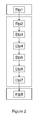
figure 2 illustre le procédé de fabrication de l'étiquette RFID. - la
figure 3 illustre la machine selon le procédé de fabrication de l'étiquette RFID.
- the
figure 1 represents a cross section of the RFID tag; - the
figure 2 illustrates the process of manufacturing the RFID tag. - the
figure 3 illustrates the machine according to the method of manufacturing the RFID tag.
En référence à la
- une couche fonctionnelle (3) comprenant au moins :
- o un composant électronique (301),
- o une antenne connectée au composant électronique (301) ;
- une couche supérieure (1) ;
- une couche inférieure (2) ayant une surface adhésive ;
caractérisée en ce que les couches supérieure et inférieure sont constituées d'une ou plusieurs matières aptes à résister au rayonnement ultraviolet et/ou à filtrer le rayonnement ultraviolet et à protéger l'étiquette contre ceux-ci.
- a functional layer (3) comprising at least:
- an electronic component (301),
- an antenna connected to the electronic component (301);
- an upper layer (1);
- a lower layer (2) having an adhesive surface;
characterized in that the upper and lower layers consist of one or more materials capable of resisting ultraviolet radiation and / or filtering ultraviolet radiation and protecting the label therefrom.
La couche supérieure (1) est, par exemple, un support en polyester ayant une épaisseur variant de 15 µm à 200 µm.The upper layer (1) is, for example, a polyester support having a thickness ranging from 15 microns to 200 microns.
La couche fonctionnelle (3) est un support, par exemple, en PET (polyéthylène téréphtalate) sur lequel est gravée une antenne, par exemple, en aluminium, connectée à un composant électronique (301) haute fréquence ou ultra-haute fréquence, par exemple, en silicium. Selon l'intégrateur et le type de protocole, le design de l'antenne et le type de composant électronique (301) sont variables.The functional layer (3) is a support, for example, PET (polyethylene terephthalate) on which is etched an antenna, for example, aluminum, connected to an electronic component (301) high frequency or ultra-high frequency, for example, silicon. Depending on the integrator and the type of protocol, the antenna design and the type of electronic component (301) are variable.
La couche inférieure (2) est, par exemple, un support en acrylique ou PET possédant une face auto-adhésive et ayant une épaisseur variant, par exemple, de 15 µm à 200 µm.The lower layer (2) is, for example, an acrylic or PET support having a self-adhesive face and having a thickness varying, for example, from 15 μm to 200 μm.
La face autoadhésive de la couche inférieure (2) est protégée par une couche détachable (4) siliconée, en papier ou en matière synthétique ayant une épaisseur variant, par exemple, de 15 µm à 120 µm. La couche détachable (4) permet une protection contre les salissures et le collage involontaire de la surface auto-adhésive de l'étiquette RFID. La face opposée à la face autoadhésive de la couche inférieure (2) est apte à être imprimée.The self-adhesive face of the lower layer (2) is protected by a release layer (4) silicone, paper or plastic having a thickness ranging, for example, from 15 microns to 120 microns. The detachable layer (4) provides protection against soiling and unintentional sticking of the self-adhesive surface of the RFID tag. The face opposite the self-adhesive face of the lower layer (2) is printable.
La colle utilisée pour la surface auto-adhésive de la couche inférieure (2) est une colle résistant aux rayonnements UV.The adhesive used for the self-adhesive surface of the lower layer (2) is a glue resistant to UV radiation.
De manière non-limitative, la face opposée à la face autoadhésive de la couche inférieure (2) est apte à être imprimée par des encres, par exemple flexographiques, permettant une protection contre un rayonnement ultraviolet de l'étiquette RFID. L'impression de la couche inférieure (2) par des encres permettant une protection contre un rayonnement ultraviolet permet de créer une couche (5) de protection supplémentaire de l'étiquette (0) contre le rayonnement UV. La couche (5) de protection supplémentaire est réalisée, par exemple, par une couche flexographique noire, par une couche sérigraphique blanche et par une impression sérigraphique. L'impression sérigraphique est d'abord réalisée, puis la couche sérigraphique blanche, puis la couche flexographique noire. Ceci permet en outre une protection du composant électronique et de l'antenne contre le rayonnement ultraviolet.In a nonlimiting manner, the face opposite to the self-adhesive face of the lower layer (2) is able to be printed by inks, for example flexographic, allowing protection against ultraviolet radiation of the RFID tag. The printing of the lower layer (2) with inks providing protection against ultraviolet radiation makes it possible to create an additional layer (5) for protecting the label (0) against UV radiation. The additional protective layer (5) is made, for example, by a black flexographic layer, a white screen printing layer and a screen printing. The screen printing is first done, then the white screenprint, then the black flexographic layer. This further allows protection of the electronic component and the antenna against ultraviolet radiation.
De manière non-limitative, la protection contre le rayonnement ultraviolet de l'étiquette peut être assurée par une combinaison d'encres aptes à résister au rayonnement ultraviolet et/ou à filtrer le rayonnement ultraviolet. Plusieurs couches d'impression d'une même encre sont aptes à résister au rayonnement ultraviolet et/ou à filtrer le rayonnement ultraviolet.In a nonlimiting manner, the protection against ultraviolet radiation of the label may be provided by a combination of inks capable of resisting ultraviolet radiation and / or filtering ultraviolet radiation. Several printing layers of the same ink are able to resist ultraviolet radiation and / or to filter ultraviolet radiation.
La couche fonctionnelle (3) est prise en sandwich entre la couche supérieure (1) et la couche inférieure (2).The functional layer (3) is sandwiched between the upper layer (1) and the lower layer (2).
En référence aux
Avant le passage sur la presse (10), la couche inférieure (2) et la couche supérieure (1) sont alimentées en continu par des bobines (103, 203) fournissant des bandes de largeur au moins égale à un multiple d'une des dimensions de l'étiquette RFID (0) permettant une fabrication d'étiquettes RFID (0) en continu.Before passing on the press (10), the lower layer (2) and the upper layer (1) are fed continuously by coils (103, 203) providing bands of width at least equal to a multiple of one of the dimensions of the RFID tag (0) for continuous RFID tagging (0).
La couche fonctionnelle (3) est alimentée en continu par au moins une bobine (3031, 3032) fournissant au moins une bande en parallèle permettant ainsi une fabrication en continu de séries d'au moins une étiquette RFID (0).The functional layer (3) is fed continuously by at least one coil (3031, 3032) providing at least one strip in parallel, thus enabling continuous production of sets of at least one RFID tag (0).
Selon une configuration, la largeur des bandes est au moins égale à un multiple de la largeur de l'étiquette RFID (0).In one configuration, the width of the strips is at least one multiple of the width of the RFID tag (0).
Selon une autre configuration, la largeur des bandes est au moins égale à un multiple de la longueur de l'étiquette RFID (0).In another configuration, the width of the strips is at least equal to a multiple of the length of the RFID tag (0).
Dans une première étape (Etp1), la bande de la bobine (203) constituant la couche inférieure (2) est dévidée afin de permettre la pré-impression en continu de la bande de la couche inférieure (2) pour une pluralité d'étiquettes. La pré-impression de la couche inférieure (2) est réalisée sur une presse. L'impression permet la protection de l'étiquette RFID (0) contre le rayonnement ultraviolet. Les séries d'étiquettes en sortie de l'étape (Etp1) peuvent, par exemple, être présentées sous forme de bobineaux d'étiquettes.In a first step (Etp1), the web of the reel (203) constituting the lower layer (2) is unwound in order to allow continuous pre-printing of the web of the lower layer (2) for a plurality of labels . The pre-printing of the lower layer (2) is performed on a press. The printing allows the protection of the RFID tag (0) against ultraviolet radiation. The series of labels at the output of the step (Etp1) can, for example, be presented in the form of label reels.
Cette étape (Etp1) peut être accompagnée d'une étape de prédécoupage en continu de la bande de la couche inférieure (2) en une pluralité d'étiquettes aux dimensions de l'étiquette RFID (0).This step (Etp1) may be accompanied by a continuous pre-cutting step of the band of the lower layer (2) into a plurality of labels to the dimensions of the RFID tag (0).
Selon une configuration, une étape suivante (Etp2) consiste au contre-collage en continu ou au dépôt de la pluralité d'étiquettes de la couche inférieure (2), réalisées à l'étape précédente sur la couche détachable (4) à l'aide de têtes d'étiquetage automatique.According to a configuration, a following step (Etp2) consists of continuous lamination or deposition of the plurality of labels of the layer lower (2), made in the previous step on the detachable layer (4) using automatic labeling heads.
Si une étape de prédécoupage a été effectuée à l'étape précédente (Etp1), une étape d'échenillage est effectuée afin de retirer les parties inutiles de la bande de la couche inférieure (2).If a precut step has been performed in the previous step (Etp1), a stripping step is performed to remove unnecessary portions of the lower layer band (2).
Dans une étape suivante (Etp3), la bande de la bobine (103) constituant le matériau de la couche supérieure (1) est dévidée en continu afin de permettre l'impression en continu des bandes des couches supérieures (1). L'impression est réalisée en ligne.In a next step (Etp3), the strip of the coil (103) constituting the material of the upper layer (1) is unwound continuously in order to allow continuous printing of the strips of the upper layers (1). The printing is done online.
Dans une étape suivante (Etp4), les bobines (3031, 3032) constituant la couche fonctionnelle (3) sont dévidées en continu pour être déposées en continu sur le complexe, constitué de la couche détachable (4) et la couche inférieure (2). De la colle est déposée sur le complexe. La colle utilisée est, de manière non-limitative, une colle thermofusible, ou à base aqueuse ou à base solvant ou toute autre colle apte à maintenir efficacement et durablement ensemble les couches de l'étiquette RFID (0). Les bandes constituant la couche fonctionnelle (3) sont découpées en continu en couches fonctionnelles individuelles. Chaque couche fonctionnelle (3) est alors déposée en continu sur la zone encollée du complexe.In a following step (Etp4), the coils (3031, 3032) constituting the functional layer (3) are unwound continuously to be deposited continuously on the complex, consisting of the detachable layer (4) and the lower layer (2) . Glue is deposited on the complex. The adhesive used is, in a non-limiting manner, a hot-melt glue, or water-based or solvent-based or any other glue able to effectively and durably maintain together the layers of the RFID tag (0). The strips constituting the functional layer (3) are continuously cut into individual functional layers. Each functional layer (3) is then continuously deposited on the glued area of the complex.
Dans une étape suivante (Etp5), la bobine (103) constituant la couche supérieure (1) est dévidée en continu pour déposer en continu la bande de la couche supérieure (1) sur les couches fonctionnelles (3) collées sur la couche inférieure (2) à l'étape précédente (Etp4). De la colle est déposée sur la surface intérieure de la couche supérieure (1) avant de venir la coller sur le complexe par mise en pression.In a next step (Etp5), the coil (103) constituting the upper layer (1) is unwound continuously to continuously deposit the band of the upper layer (1) on the functional layers (3) bonded to the lower layer ( 2) in the previous step (Etp4). Glue is deposited on the inner surface of the upper layer (1) before coming to stick on the complex by pressurizing.
Dans une étape suivante (Etp6), un façonnage des étiquettes RFID est réalisé.In a next step (Etp6), a shaping of the RFID tags is performed.
Selon une configuration, les bandes assemblées aux étapes précédentes sont découpées longitudinalement en continu afin d'obtenir une pluralité de bandes de dimensions au moins égales à la longueur ou la largeur d'une étiquette RFID (0) et dont le nombre de bandes est égal au nombre de bobines de couche fonctionnelle (3). Chaque bande obtenue est ensuite enroulée sous forme de bobineaux.According to one configuration, the strips assembled in the preceding steps are cut longitudinally continuously to obtain a plurality of strips of dimensions at least equal to the length or the width of an RFID tag (0) and whose number of bands is equal at number of functional layer coils (3). Each band obtained is then wound in the form of coils.
Selon une autre configuration, les bandes assemblées aux étapes précédentes sont découpées longitudinalement en continu afin d'obtenir une pluralité de bandes de dimensions au moins égales à la longueur d'une étiquette RFID (0) et dont le nombre de bandes est égal au nombre de bobines de couche fonctionnelle (3). Chaque bande subit une série de lignes de perforations pour conditionner les bandes d'étiquettes RFID en paravents ou pour plier les bandes et séparer les étiquettes RFID (0) facilement. La distance entre chaque ligne de perforations est égale au moins à la largeur d'une étiquette RFID (0).According to another configuration, the strips assembled in the preceding steps are cut longitudinally continuously to obtain a plurality of strips of dimensions at least equal to the length of an RFID tag (0) and whose number of bands is equal to the number functional layer coils (3). Each strip undergoes a series of perforation lines to package the RFID tag strips into screens or to fold the strips and separate the RFID tags (0) easily. The distance between each line of perforations is at least equal to the width of an RFID tag (0).
Selon une autre configuration, les bandes assemblées aux étapes précédentes sont découpées longitudinalement en continu afin d'obtenir une pluralité de bandes de dimension au moins égale à la largeur d'une étiquette RFID (0) et dont le nombre de bandes est égal au nombre de bobines de couche fonctionnelle (3). Chaque bande subit une série de lignes de perforations pour conditionner les bandes d'étiquettes RFID en paravents ou pour plier les bandes et séparer les étiquettes RFID (0) facilement. La distance entre chaque ligne de perforations est égale au moins à la longueur de l'étiquette RFID (0).According to another configuration, the strips assembled in the preceding steps are cut longitudinally continuously in order to obtain a plurality of strips of dimension at least equal to the width of an RFID tag (0) and whose number of bands is equal to the number functional layer coils (3). Each strip undergoes a series of perforation lines to package the RFID tag strips into screens or to fold the strips and separate the RFID tags (0) easily. The distance between each line of perforations is at least equal to the length of the RFID tag (0).
Selon une autre configuration, les bandes assemblées aux étapes précédentes sont découpées en continu en étiquettes RFID (0) individuelles.In another configuration, the strips assembled in the previous steps are continuously cut into individual RFID (0) tags.
Dans une étape suivante (Etp7), le bon fonctionnement de chaque système de composant électronique (301) connecté à une antenne, de chaque étiquette RFID (0) est contrôlé en continu grâce à une antenne de lecture.In a next step (Etp7), the proper functioning of each electronic component system (301) connected to an antenna, of each RFID tag (0) is continuously monitored by means of a reading antenna.
Dans une étape suivante non représentée, chaque composant électronique associé à une étiquette subit une personnalisation graphique et électrique. Quelle que soit la présentation du produit en bobineaux, en paravents ou en étiquettes individuelles, lors de la personnalisation, suivant les besoins, une lecture d'un identifiant, un codage du composant électronique et un numérotage, permettant ensuite son impression sont, par exemple, possibles, ainsi que la création d'un fichier log ou autre selon la demande.In a next step not shown, each electronic component associated with a label undergoes graphic and electrical customization. Whatever the presentation of the product in reels, screens or individual labels, during personalization, as needed, a reading of an identifier, an encoding of the electronic component and a numbering, then allowing its printing are, by example, possible, as well as the creation of a log file or other according to the request.
Dans une étape suivante (Etp8), les bobineaux, les paravents et les étiquettes individuelles peuvent être conditionnés suivant les besoins ou la demande d'un client.In a next step (Etp8), the windings, the screens and the individual labels can be packaged according to the needs or the request of a customer.
En référence à la
- un poste d'alimentation (501) par bobine (203) de la couche inférieure (2),
- un poste d'alimentation (502) par bobine (103) de la couche supérieure (1),
- un poste (505) comportant au moins un module d'alimentation par bobine (3031, 3032) de bandes de la couche fonctionnelle (3).
- au moins un poste d'impression (504) de la couche supérieure (1). Préférentiellement, la machine de production (10) comporte en outre :
- un poste d'alimentation (5001) par bobine de la couche détachable (4)
- deux têtes d'étiquetage automatique (503) pour le dépôt en continu de la surface inférieure adhésive de la bande de la couche inférieure (2) sur la bande de la couche détachable (4),
- a feed station (501) for each coil (203) of the lower layer (2),
- a feed station (502) for each coil (103) of the upper layer (1),
- a station (505) comprising at least one reel feeding module (3031, 3032) of bands of the functional layer (3).
- at least one printing station (504) of the upper layer (1). Preferably, the production machine (10) further comprises:
- a feeding station (5001) for each coil of the detachable layer (4)
- two automatic labeling heads (503) for continuously depositing the lower adhesive surface of the lower layer strip (2) on the strip of the release layer (4),
Préférentiellement, la machine de production (10) comporte en outre :
- un poste de façonnage (506) pour le découpage,
- un poste de façonnage (507) pour la présentation des étiquettes RFID (0) en bobineaux, en paravents ou en étiquettes RFID individuelles.
- a forming station (506) for cutting,
- a forming station (507) for presenting the RFID tags (0) in reels, screens or individual RFID tags.
Il doit être évident pour les personnes versées dans l'art que la présente invention permet des modes de réalisation sous de nombreuses autres formes spécifiques sans l'éloigner du domaine d'application de l'invention comme revendiqué. Par conséquent, les présents modes de réalisation doivent être considérés à titre d'illustration, mais peuvent être modifiés dans le domaine défini par la portée des revendications jointes, et l'invention ne doit pas être limitée aux détails donnés ci-dessus.It should be obvious to those skilled in the art that the present invention allows embodiments in many other specific forms without departing from the scope of the invention as claimed. Therefore, the present embodiments should be considered by way of illustration, but may be modified in the field defined by the scope of the appended claims, and the invention should not be limited to the details given above.
Claims (17)
caractérisée en ce que les couches supérieure et inférieure sont constituées d'une ou plusieurs matières aptes à résister au rayonnement ultraviolet et/ou à filtrer le rayonnement ultraviolet.
characterized in that the upper and lower layers consist of one or more materials capable of resisting ultraviolet radiation and / or filtering ultraviolet radiation.
en ce que la couche fonctionnelle (3) est alimentée en continu par au moins une bobine (3031, 3032) fournissant au moins une bande en parallèle
et en ce qu'il comporte au moins les étapes suivantes :
in that the functional layer (3) is fed continuously by at least one coil (3031, 3032) providing at least one band in parallel
and in that it comprises at least the following steps:
Applications Claiming Priority (1)
| Application Number | Priority Date | Filing Date | Title |
|---|---|---|---|
| FR0901619A FR2944124B1 (en) | 2009-04-03 | 2009-04-03 | RADIO FREQUENCY IDENTIFICATION LABEL (RFID) AND METHOD OF MANUFACTURING THE LABEL |
Publications (2)
| Publication Number | Publication Date |
|---|---|
| EP2237194A1 true EP2237194A1 (en) | 2010-10-06 |
| EP2237194B1 EP2237194B1 (en) | 2013-06-05 |
Family
ID=41264039
Family Applications (1)
| Application Number | Title | Priority Date | Filing Date |
|---|---|---|---|
| EP10159053.7A Not-in-force EP2237194B1 (en) | 2009-04-03 | 2010-04-02 | Radiofrequency identification (RFID) tag and method for manufacturing such a tag |
Country Status (4)
| Country | Link |
|---|---|
| US (2) | US8564442B2 (en) |
| EP (1) | EP2237194B1 (en) |
| CA (1) | CA2699001C (en) |
| FR (1) | FR2944124B1 (en) |
Families Citing this family (5)
| Publication number | Priority date | Publication date | Assignee | Title |
|---|---|---|---|---|
| FR2944124B1 (en) * | 2009-04-03 | 2012-05-11 | Paragon Identification | RADIO FREQUENCY IDENTIFICATION LABEL (RFID) AND METHOD OF MANUFACTURING THE LABEL |
| MX346259B (en) * | 2015-02-24 | 2017-03-10 | Validation Security Tech Identification S De R L De C V | Intelligent label system. |
| EP3327634B1 (en) * | 2016-11-25 | 2023-11-01 | Confidex Oy | Rfid transponder web |
| DE212020000366U1 (en) * | 2019-11-25 | 2021-02-23 | Murata Manufacturing Co., Ltd. | RFIC module and RFID transponder |
| US20230259732A1 (en) * | 2020-05-26 | 2023-08-17 | Pascal Tags Inc. | Passive Identification Tags Including Resonant Structures and Characteristic Layers |
Citations (6)
| Publication number | Priority date | Publication date | Assignee | Title |
|---|---|---|---|---|
| US5528222A (en) * | 1994-09-09 | 1996-06-18 | International Business Machines Corporation | Radio frequency circuit and memory in thin flexible package |
| EP1411465A1 (en) * | 2001-06-19 | 2004-04-21 | Nippon Carbide Kogyo Kabushiki Kaisha | Retroreflective product in which integrated circuit is sealed |
| EP1562140A2 (en) * | 2004-02-05 | 2005-08-10 | Hitachi Ltd. | Paper RFID tag and method of manufacturing the same |
| EP1612723A2 (en) * | 2000-01-17 | 2006-01-04 | Rafsec OY | Smart label web and manufacturing procedure thereof |
| EP1720121A2 (en) * | 2005-04-27 | 2006-11-08 | Paxar Americas, Inc. | RFID and antenna webs and methods of making same |
| WO2006122266A2 (en) * | 2005-05-10 | 2006-11-16 | Precision Dynamics Corporation | Continuous lamination of rfid tags and inlets |
Family Cites Families (12)
| Publication number | Priority date | Publication date | Assignee | Title |
|---|---|---|---|---|
| US6389206B1 (en) * | 1998-07-16 | 2002-05-14 | Brookhaven Science Associates | Light redirective display panel and a method of making a light redirective display panel |
| JP2003529163A (en) * | 2000-03-28 | 2003-09-30 | ルカトロン アーゲー | RFID label having member for adjusting resonance frequency |
| JP4289152B2 (en) * | 2001-09-03 | 2009-07-01 | 王子製紙株式会社 | Baggage tag and how to use baggage tag |
| US7135979B2 (en) * | 2002-11-14 | 2006-11-14 | Brady Worldwide, Inc. | In-mold radio frequency identification device label |
| US7120987B2 (en) * | 2003-08-05 | 2006-10-17 | Avery Dennison Corporation | Method of making RFID device |
| US20070193095A1 (en) * | 2003-08-28 | 2007-08-23 | Section 1 Llc | Miniature print publication with electronic tie-in |
| US7135973B2 (en) * | 2004-02-13 | 2006-11-14 | Avery Dennison Corporation | Tamper monitoring article, system and method |
| US7259106B2 (en) * | 2004-09-10 | 2007-08-21 | Versatilis Llc | Method of making a microelectronic and/or optoelectronic circuitry sheet |
| US7410825B2 (en) * | 2005-09-15 | 2008-08-12 | Eastman Kodak Company | Metal and electronically conductive polymer transfer |
| US20070163704A1 (en) * | 2006-01-18 | 2007-07-19 | Upm Rafsec Oy | Method for manufacturing a label comprising a transponder |
| TWM362470U (en) * | 2007-07-20 | 2009-08-01 | Wee Soon Leonard Huat | Separated wireless identification device for handheld device |
| FR2944124B1 (en) * | 2009-04-03 | 2012-05-11 | Paragon Identification | RADIO FREQUENCY IDENTIFICATION LABEL (RFID) AND METHOD OF MANUFACTURING THE LABEL |
-
2009
- 2009-04-03 FR FR0901619A patent/FR2944124B1/en not_active Expired - Fee Related
-
2010
- 2010-04-02 EP EP10159053.7A patent/EP2237194B1/en not_active Not-in-force
- 2010-04-02 US US12/753,315 patent/US8564442B2/en active Active
- 2010-04-06 CA CA2699001A patent/CA2699001C/en not_active Expired - Fee Related
-
2013
- 2013-09-23 US US14/033,659 patent/US9202163B2/en not_active Expired - Fee Related
Patent Citations (6)
| Publication number | Priority date | Publication date | Assignee | Title |
|---|---|---|---|---|
| US5528222A (en) * | 1994-09-09 | 1996-06-18 | International Business Machines Corporation | Radio frequency circuit and memory in thin flexible package |
| EP1612723A2 (en) * | 2000-01-17 | 2006-01-04 | Rafsec OY | Smart label web and manufacturing procedure thereof |
| EP1411465A1 (en) * | 2001-06-19 | 2004-04-21 | Nippon Carbide Kogyo Kabushiki Kaisha | Retroreflective product in which integrated circuit is sealed |
| EP1562140A2 (en) * | 2004-02-05 | 2005-08-10 | Hitachi Ltd. | Paper RFID tag and method of manufacturing the same |
| EP1720121A2 (en) * | 2005-04-27 | 2006-11-08 | Paxar Americas, Inc. | RFID and antenna webs and methods of making same |
| WO2006122266A2 (en) * | 2005-05-10 | 2006-11-16 | Precision Dynamics Corporation | Continuous lamination of rfid tags and inlets |
Also Published As
| Publication number | Publication date |
|---|---|
| FR2944124B1 (en) | 2012-05-11 |
| US8564442B2 (en) | 2013-10-22 |
| FR2944124A1 (en) | 2010-10-08 |
| CA2699001C (en) | 2019-09-03 |
| US20140021263A1 (en) | 2014-01-23 |
| EP2237194B1 (en) | 2013-06-05 |
| US20100253523A1 (en) | 2010-10-07 |
| US9202163B2 (en) | 2015-12-01 |
| CA2699001A1 (en) | 2010-10-03 |
Similar Documents
| Publication | Publication Date | Title |
|---|---|---|
| EP2237194B1 (en) | Radiofrequency identification (RFID) tag and method for manufacturing such a tag | |
| EP1016037B1 (en) | Method and system for issuing identification labels | |
| CN106903970B (en) | Method of manufacturing radio frequency identification device | |
| US7842152B2 (en) | Method of making RFID devices | |
| EP2237193A1 (en) | Semi-rigid radiofrequency identification (RFID) card, manufacturing method and machine for manufacturing same | |
| GB2542111B (en) | Label assembly | |
| US20070006969A1 (en) | Method and apparatus for manufacturing pressure sensitive adhesive label stocks with printing under adhesive and product produced thereby | |
| US20180240369A1 (en) | In-line production of linerless labels | |
| US20100134294A1 (en) | Method of and apparatus for making an rfid label | |
| US20050091821A1 (en) | Method of manufacturing an article having a radio frequency identification (RFID) device | |
| US20050087977A1 (en) | Composite form assembly with frangible bonded layers formed in-situ | |
| US10906346B2 (en) | System and method of manufacturing extended content labels | |
| AU2009244023B2 (en) | Printing carrier consisting of at least two flat partial printing carriers assembled in a coplanar manner, partial printing carriers, and method for the production thereof | |
| US7294219B2 (en) | Label-seal manufacturing method and the resulting improved label-seal | |
| CN104608516A (en) | Normal-temperature stamping method, anti-counterfeiting marker and anti-counterfeiting packaging material thereof | |
| CN107195242B (en) | Anti-counterfeit label, anti-counterfeit label product and manufacturing method thereof | |
| US20070163703A1 (en) | Card and mailing incorporating the card and system and method for producing the same | |
| US20070085338A1 (en) | Frangible card carrier with removable layer provided in a temporary laminated assembly | |
| FR2963701A1 (en) | Adhesive label holder for use on bottles for conditioning e.g. shampoo, in e.g. cosmetic industry, has holder band formed from film, and labels formed from another film, which is transparent and identical to former film | |
| JP3141346U (en) | Anti-tamper label | |
| EP3447753A1 (en) | Secure data tag, secure document, and method for obtaining same | |
| US20070026202A1 (en) | Filament based open celled carrier web system for pressure sensitive product assemblies | |
| EP1168280A1 (en) | Method for Producing labels | |
| EP2874816A1 (en) | Multi-function labels | |
| FR2975379A1 (en) | Method for irreversibly integrating adhesive authentication label in e.g. shrinkable envelope used to package e.g. money, involves realizing flexible package from films by shaping operations |
Legal Events
| Date | Code | Title | Description |
|---|---|---|---|
| PUAI | Public reference made under article 153(3) epc to a published international application that has entered the european phase |
Free format text: ORIGINAL CODE: 0009012 |
|
| AK | Designated contracting states |
Kind code of ref document: A1 Designated state(s): AT BE BG CH CY CZ DE DK EE ES FI FR GB GR HR HU IE IS IT LI LT LU LV MC MK MT NL NO PL PT RO SE SI SK SM TR |
|
| AX | Request for extension of the european patent |
Extension state: AL BA ME RS |
|
| 17P | Request for examination filed |
Effective date: 20110405 |
|
| 17Q | First examination report despatched |
Effective date: 20111031 |
|
| GRAP | Despatch of communication of intention to grant a patent |
Free format text: ORIGINAL CODE: EPIDOSNIGR1 |
|
| GRAS | Grant fee paid |
Free format text: ORIGINAL CODE: EPIDOSNIGR3 |
|
| GRAA | (expected) grant |
Free format text: ORIGINAL CODE: 0009210 |
|
| AK | Designated contracting states |
Kind code of ref document: B1 Designated state(s): AT BE BG CH CY CZ DE DK EE ES FI FR GB GR HR HU IE IS IT LI LT LU LV MC MK MT NL NO PL PT RO SE SI SK SM TR |
|
| REG | Reference to a national code |
Ref country code: GB Ref legal event code: FG4D Free format text: NOT ENGLISH |
|
| REG | Reference to a national code |
Ref country code: CH Ref legal event code: EP |
|
| REG | Reference to a national code |
Ref country code: AT Ref legal event code: REF Ref document number: 616031 Country of ref document: AT Kind code of ref document: T Effective date: 20130615 |
|
| REG | Reference to a national code |
Ref country code: IE Ref legal event code: FG4D Free format text: LANGUAGE OF EP DOCUMENT: FRENCH |
|
| REG | Reference to a national code |
Ref country code: DE Ref legal event code: R096 Ref document number: 602010007488 Country of ref document: DE Effective date: 20130801 |
|
| REG | Reference to a national code |
Ref country code: AT Ref legal event code: MK05 Ref document number: 616031 Country of ref document: AT Kind code of ref document: T Effective date: 20130605 |
|
| PG25 | Lapsed in a contracting state [announced via postgrant information from national office to epo] |
Ref country code: LT Free format text: LAPSE BECAUSE OF FAILURE TO SUBMIT A TRANSLATION OF THE DESCRIPTION OR TO PAY THE FEE WITHIN THE PRESCRIBED TIME-LIMIT Effective date: 20130605 Ref country code: NO Free format text: LAPSE BECAUSE OF FAILURE TO SUBMIT A TRANSLATION OF THE DESCRIPTION OR TO PAY THE FEE WITHIN THE PRESCRIBED TIME-LIMIT Effective date: 20130905 Ref country code: FI Free format text: LAPSE BECAUSE OF FAILURE TO SUBMIT A TRANSLATION OF THE DESCRIPTION OR TO PAY THE FEE WITHIN THE PRESCRIBED TIME-LIMIT Effective date: 20130605 Ref country code: SI Free format text: LAPSE BECAUSE OF FAILURE TO SUBMIT A TRANSLATION OF THE DESCRIPTION OR TO PAY THE FEE WITHIN THE PRESCRIBED TIME-LIMIT Effective date: 20130605 Ref country code: SE Free format text: LAPSE BECAUSE OF FAILURE TO SUBMIT A TRANSLATION OF THE DESCRIPTION OR TO PAY THE FEE WITHIN THE PRESCRIBED TIME-LIMIT Effective date: 20130605 Ref country code: GR Free format text: LAPSE BECAUSE OF FAILURE TO SUBMIT A TRANSLATION OF THE DESCRIPTION OR TO PAY THE FEE WITHIN THE PRESCRIBED TIME-LIMIT Effective date: 20130906 Ref country code: AT Free format text: LAPSE BECAUSE OF FAILURE TO SUBMIT A TRANSLATION OF THE DESCRIPTION OR TO PAY THE FEE WITHIN THE PRESCRIBED TIME-LIMIT Effective date: 20130605 Ref country code: ES Free format text: LAPSE BECAUSE OF FAILURE TO SUBMIT A TRANSLATION OF THE DESCRIPTION OR TO PAY THE FEE WITHIN THE PRESCRIBED TIME-LIMIT Effective date: 20130916 |
|
| REG | Reference to a national code |
Ref country code: NL Ref legal event code: VDEP Effective date: 20130605 |
|
| REG | Reference to a national code |
Ref country code: LT Ref legal event code: MG4D |
|
| PG25 | Lapsed in a contracting state [announced via postgrant information from national office to epo] |
Ref country code: BG Free format text: LAPSE BECAUSE OF FAILURE TO SUBMIT A TRANSLATION OF THE DESCRIPTION OR TO PAY THE FEE WITHIN THE PRESCRIBED TIME-LIMIT Effective date: 20130905 Ref country code: HR Free format text: LAPSE BECAUSE OF FAILURE TO SUBMIT A TRANSLATION OF THE DESCRIPTION OR TO PAY THE FEE WITHIN THE PRESCRIBED TIME-LIMIT Effective date: 20130605 |
|
| PG25 | Lapsed in a contracting state [announced via postgrant information from national office to epo] |
Ref country code: LV Free format text: LAPSE BECAUSE OF FAILURE TO SUBMIT A TRANSLATION OF THE DESCRIPTION OR TO PAY THE FEE WITHIN THE PRESCRIBED TIME-LIMIT Effective date: 20130605 |
|
| PG25 | Lapsed in a contracting state [announced via postgrant information from national office to epo] |
Ref country code: EE Free format text: LAPSE BECAUSE OF FAILURE TO SUBMIT A TRANSLATION OF THE DESCRIPTION OR TO PAY THE FEE WITHIN THE PRESCRIBED TIME-LIMIT Effective date: 20130605 Ref country code: PT Free format text: LAPSE BECAUSE OF FAILURE TO SUBMIT A TRANSLATION OF THE DESCRIPTION OR TO PAY THE FEE WITHIN THE PRESCRIBED TIME-LIMIT Effective date: 20131007 Ref country code: CZ Free format text: LAPSE BECAUSE OF FAILURE TO SUBMIT A TRANSLATION OF THE DESCRIPTION OR TO PAY THE FEE WITHIN THE PRESCRIBED TIME-LIMIT Effective date: 20130605 Ref country code: SK Free format text: LAPSE BECAUSE OF FAILURE TO SUBMIT A TRANSLATION OF THE DESCRIPTION OR TO PAY THE FEE WITHIN THE PRESCRIBED TIME-LIMIT Effective date: 20130605 Ref country code: IS Free format text: LAPSE BECAUSE OF FAILURE TO SUBMIT A TRANSLATION OF THE DESCRIPTION OR TO PAY THE FEE WITHIN THE PRESCRIBED TIME-LIMIT Effective date: 20131005 |
|
| PG25 | Lapsed in a contracting state [announced via postgrant information from national office to epo] |
Ref country code: PL Free format text: LAPSE BECAUSE OF FAILURE TO SUBMIT A TRANSLATION OF THE DESCRIPTION OR TO PAY THE FEE WITHIN THE PRESCRIBED TIME-LIMIT Effective date: 20130605 Ref country code: RO Free format text: LAPSE BECAUSE OF FAILURE TO SUBMIT A TRANSLATION OF THE DESCRIPTION OR TO PAY THE FEE WITHIN THE PRESCRIBED TIME-LIMIT Effective date: 20130605 Ref country code: NL Free format text: LAPSE BECAUSE OF FAILURE TO SUBMIT A TRANSLATION OF THE DESCRIPTION OR TO PAY THE FEE WITHIN THE PRESCRIBED TIME-LIMIT Effective date: 20130605 |
|
| PLBE | No opposition filed within time limit |
Free format text: ORIGINAL CODE: 0009261 |
|
| STAA | Information on the status of an ep patent application or granted ep patent |
Free format text: STATUS: NO OPPOSITION FILED WITHIN TIME LIMIT |
|
| PG25 | Lapsed in a contracting state [announced via postgrant information from national office to epo] |
Ref country code: DK Free format text: LAPSE BECAUSE OF FAILURE TO SUBMIT A TRANSLATION OF THE DESCRIPTION OR TO PAY THE FEE WITHIN THE PRESCRIBED TIME-LIMIT Effective date: 20130605 |
|
| PGFP | Annual fee paid to national office [announced via postgrant information from national office to epo] |
Ref country code: IE Payment date: 20140319 Year of fee payment: 5 |
|
| 26N | No opposition filed |
Effective date: 20140306 |
|
| PG25 | Lapsed in a contracting state [announced via postgrant information from national office to epo] |
Ref country code: IT Free format text: LAPSE BECAUSE OF FAILURE TO SUBMIT A TRANSLATION OF THE DESCRIPTION OR TO PAY THE FEE WITHIN THE PRESCRIBED TIME-LIMIT Effective date: 20130605 |
|
| REG | Reference to a national code |
Ref country code: DE Ref legal event code: R097 Ref document number: 602010007488 Country of ref document: DE Effective date: 20140306 |
|
| PG25 | Lapsed in a contracting state [announced via postgrant information from national office to epo] |
Ref country code: LU Free format text: LAPSE BECAUSE OF FAILURE TO SUBMIT A TRANSLATION OF THE DESCRIPTION OR TO PAY THE FEE WITHIN THE PRESCRIBED TIME-LIMIT Effective date: 20140402 Ref country code: MC Free format text: LAPSE BECAUSE OF FAILURE TO SUBMIT A TRANSLATION OF THE DESCRIPTION OR TO PAY THE FEE WITHIN THE PRESCRIBED TIME-LIMIT Effective date: 20130605 |
|
| REG | Reference to a national code |
Ref country code: CH Ref legal event code: PL |
|
| PG25 | Lapsed in a contracting state [announced via postgrant information from national office to epo] |
Ref country code: CH Free format text: LAPSE BECAUSE OF NON-PAYMENT OF DUE FEES Effective date: 20140430 Ref country code: LI Free format text: LAPSE BECAUSE OF NON-PAYMENT OF DUE FEES Effective date: 20140430 |
|
| REG | Reference to a national code |
Ref country code: IE Ref legal event code: MM4A |
|
| PG25 | Lapsed in a contracting state [announced via postgrant information from national office to epo] |
Ref country code: MT Free format text: LAPSE BECAUSE OF FAILURE TO SUBMIT A TRANSLATION OF THE DESCRIPTION OR TO PAY THE FEE WITHIN THE PRESCRIBED TIME-LIMIT Effective date: 20130605 |
|
| REG | Reference to a national code |
Ref country code: FR Ref legal event code: PLFP Year of fee payment: 7 |
|
| PG25 | Lapsed in a contracting state [announced via postgrant information from national office to epo] |
Ref country code: IE Free format text: LAPSE BECAUSE OF NON-PAYMENT OF DUE FEES Effective date: 20150402 Ref country code: SM Free format text: LAPSE BECAUSE OF FAILURE TO SUBMIT A TRANSLATION OF THE DESCRIPTION OR TO PAY THE FEE WITHIN THE PRESCRIBED TIME-LIMIT Effective date: 20130605 |
|
| PG25 | Lapsed in a contracting state [announced via postgrant information from national office to epo] |
Ref country code: CY Free format text: LAPSE BECAUSE OF FAILURE TO SUBMIT A TRANSLATION OF THE DESCRIPTION OR TO PAY THE FEE WITHIN THE PRESCRIBED TIME-LIMIT Effective date: 20130605 |
|
| PG25 | Lapsed in a contracting state [announced via postgrant information from national office to epo] |
Ref country code: TR Free format text: LAPSE BECAUSE OF FAILURE TO SUBMIT A TRANSLATION OF THE DESCRIPTION OR TO PAY THE FEE WITHIN THE PRESCRIBED TIME-LIMIT Effective date: 20130605 Ref country code: HU Free format text: LAPSE BECAUSE OF FAILURE TO SUBMIT A TRANSLATION OF THE DESCRIPTION OR TO PAY THE FEE WITHIN THE PRESCRIBED TIME-LIMIT; INVALID AB INITIO Effective date: 20100402 |
|
| REG | Reference to a national code |
Ref country code: FR Ref legal event code: PLFP Year of fee payment: 8 |
|
| REG | Reference to a national code |
Ref country code: FR Ref legal event code: PLFP Year of fee payment: 9 |
|
| PG25 | Lapsed in a contracting state [announced via postgrant information from national office to epo] |
Ref country code: MK Free format text: LAPSE BECAUSE OF FAILURE TO SUBMIT A TRANSLATION OF THE DESCRIPTION OR TO PAY THE FEE WITHIN THE PRESCRIBED TIME-LIMIT Effective date: 20130605 |
|
| PGFP | Annual fee paid to national office [announced via postgrant information from national office to epo] |
Ref country code: FR Payment date: 20210423 Year of fee payment: 12 Ref country code: DE Payment date: 20210428 Year of fee payment: 12 |
|
| PGFP | Annual fee paid to national office [announced via postgrant information from national office to epo] |
Ref country code: BE Payment date: 20210427 Year of fee payment: 12 Ref country code: GB Payment date: 20210427 Year of fee payment: 12 |
|
| REG | Reference to a national code |
Ref country code: DE Ref legal event code: R119 Ref document number: 602010007488 Country of ref document: DE |
|
| GBPC | Gb: european patent ceased through non-payment of renewal fee |
Effective date: 20220402 |
|
| REG | Reference to a national code |
Ref country code: BE Ref legal event code: MM Effective date: 20220430 |
|
| PG25 | Lapsed in a contracting state [announced via postgrant information from national office to epo] |
Ref country code: GB Free format text: LAPSE BECAUSE OF NON-PAYMENT OF DUE FEES Effective date: 20220402 Ref country code: FR Free format text: LAPSE BECAUSE OF NON-PAYMENT OF DUE FEES Effective date: 20220430 Ref country code: DE Free format text: LAPSE BECAUSE OF NON-PAYMENT OF DUE FEES Effective date: 20221103 |
|
| PG25 | Lapsed in a contracting state [announced via postgrant information from national office to epo] |
Ref country code: BE Free format text: LAPSE BECAUSE OF NON-PAYMENT OF DUE FEES Effective date: 20220430 |