EP2223334B1 - Kühlkörper wenigstens eines elektrischen bauteils - Google Patents
Kühlkörper wenigstens eines elektrischen bauteils Download PDFInfo
- Publication number
- EP2223334B1 EP2223334B1 EP08863100.7A EP08863100A EP2223334B1 EP 2223334 B1 EP2223334 B1 EP 2223334B1 EP 08863100 A EP08863100 A EP 08863100A EP 2223334 B1 EP2223334 B1 EP 2223334B1
- Authority
- EP
- European Patent Office
- Prior art keywords
- heat sink
- component
- section
- sink section
- leg
- Prior art date
- Legal status (The legal status is an assumption and is not a legal conclusion. Google has not performed a legal analysis and makes no representation as to the accuracy of the status listed.)
- Active
Links
- 238000001816 cooling Methods 0.000 title description 3
- 238000002788 crimping Methods 0.000 claims 1
- 230000017525 heat dissipation Effects 0.000 description 8
- 230000001133 acceleration Effects 0.000 description 3
- 239000003990 capacitor Substances 0.000 description 3
- 150000001875 compounds Chemical class 0.000 description 3
- 230000005669 field effect Effects 0.000 description 3
- 238000004382 potting Methods 0.000 description 3
- 238000006073 displacement reaction Methods 0.000 description 1
- 230000035939 shock Effects 0.000 description 1
- 239000007787 solid Substances 0.000 description 1
Images

Classifications
-
- H—ELECTRICITY
- H01—ELECTRIC ELEMENTS
- H01L—SEMICONDUCTOR DEVICES NOT COVERED BY CLASS H10
- H01L23/00—Details of semiconductor or other solid state devices
- H01L23/34—Arrangements for cooling, heating, ventilating or temperature compensation ; Temperature sensing arrangements
- H01L23/40—Mountings or securing means for detachable cooling or heating arrangements ; fixed by friction, plugs or springs
- H01L23/4093—Snap-on arrangements, e.g. clips
-
- H—ELECTRICITY
- H01—ELECTRIC ELEMENTS
- H01L—SEMICONDUCTOR DEVICES NOT COVERED BY CLASS H10
- H01L23/00—Details of semiconductor or other solid state devices
- H01L23/34—Arrangements for cooling, heating, ventilating or temperature compensation ; Temperature sensing arrangements
- H01L23/40—Mountings or securing means for detachable cooling or heating arrangements ; fixed by friction, plugs or springs
-
- H—ELECTRICITY
- H01—ELECTRIC ELEMENTS
- H01L—SEMICONDUCTOR DEVICES NOT COVERED BY CLASS H10
- H01L2924/00—Indexing scheme for arrangements or methods for connecting or disconnecting semiconductor or solid-state bodies as covered by H01L24/00
- H01L2924/0001—Technical content checked by a classifier
- H01L2924/0002—Not covered by any one of groups H01L24/00, H01L24/00 and H01L2224/00
Definitions
- the invention is based on a heat sink of at least one electrical component according to the preamble of claim 1.
- heat sinks on electrical power components in order to ensure sufficient heat dissipation from the power component.
- heatsinks consist of a surface which makes large-area contact with the power device and fins projecting transversely thereof, which effectively increase the surface area of the heatsink and improve heat dissipation.
- the heat sink is connected to the power component by a thermal paste or a potting compound. Vibrations or strong acceleration fluctuations can damage the power component.
- the US 2004/206476 A1 shows a heat sink in which a component between two legs of a first heat sink portion of the heat sink can be clamped by the heat sink is pushed from above over the component.
- the heat sink is soldered to a contact pin on a board located behind the contact pins of the device. Laterally angled heat sink sections serve as additional cooling surface and stand on the board.
- the invention is based on a heat sink of at least one electrical component.
- a first heat sink section is designed as a spring, wherein a contact surface between the heat sink and the at least one component is provided in the first heat sink section.
- the first heat sink portion is angled transversely to a second heat sink portion, wherein the second heat sink portion is provided in the assembled state for fixing the heat sink to a circuit board.
- the first heat sink section can be moved flexibly against the second heat sink section. Vibrations can be easily cushioned.
- the first heat sink section is bow-shaped with a first leg and a second leg. By the bow-shaped configuration, an advantageous spring effect of the heat sink can be supported.
- the design makes it possible to ensure a secure and reliable planar abutment of the heat sink on the at least one component and thus both secure fixing of the at least one component and reliable heat dissipation. It can be made a reliable connection with the at least one component and an advantageous compact and narrow design of the heat sink can be achieved.
- an electrical component connected to the heat sink on the first heat sink section can be protected by the spring action of the heat sink section, for example, in the case of vibrations, impact or acceleration fluctuations.
- the spring action of the heat sink can hold the electrical component in deformations, for example, after strong acceleration fluctuations and return to the original position.
- the first heat sink section can be connected to a second heat sink section in such a way that this first heat sink section can be deflected, for example, resiliently with respect to the second heat sink section.
- the first heat sink section can be angled against the second heat sink section or connected to a spring element. If the second heat sink section is rigidly fixed, shocks or vibrations may pass through the first heat sink section be intercepted.
- On the heat sink and a plurality of components to be cooled may be arranged, wherein at least one of the components in the manner described is mechanically and thermally connected as a result thereof.
- the second heat sink section can be fastened to a circuit board with at least one fastening element in the mounted state.
- the board can be clamped.
- the at least one fastener may preferably be used as a catch or be designed as Crimpfuß and engage in corresponding recesses in the board. Thereby, a mechanical hold of the heat sink can be achieved on the board without additional fasteners.
- a solid cohesion of board and heat sink can be achieved with and without additional potting compound.
- the attachment can also be made so that the board is inserted on the heat sink section. A fixation against displacement, for example, by a potting compound, which is arranged for example over the junction board / heatsink section, be ensured.
- the first heat sink section can be clamped to the at least one component.
- the first heat sink section may be provided for bearing against a main surface of the at least one component.
- two guide elements may be formed, which may be e.g. juxtaposed side surfaces of the component and e.g. serve the leadership of at least one component.
- the contact surface may be arranged on an inner side of at least one of the legs. Then, the at least one component in a cavity between the legs be arranged.
- the at least one component can be clamped between the first and the second leg. The heat transfer can be ensured by the clamping force of the two legs, and the at least one component can be securely fixed.
- further electrical components attached to one or both legs for example screwed, are.
- the component arranged between the legs can be a capacitor, while other components, for example field effect transistors, can be arranged on the outside of one or both legs.
- the contact surface may be arranged on an outer side of one of the legs.
- the heat transfer can be ensured by a contact pressure between the at least one component and the heat sink.
- the at least one component between the contact surface on the outside of one of the legs and a further clamping portion in the heat sink be clamped.
- the clamping portion can be punched out of the heat sink and suitably bent.
- other electrical components may be disposed on the first heat sink portion on the outside thereof, e.g. be bolted to an outside.
- the heat sink can be produced inexpensively as a stamped part, in which the first heat sink section, the guide elements, clamping element and fastening elements can be angled in a suitable manner.
- the assembly of the heat sink or the component can be done quickly and inexpensively.
- the Fig. 1 a and 1b is a first preferred embodiment of a cooling body 10 in a perspective view ( 1a ) or side view ( Fig. 1 b) refer to.
- An electrical component 42 mounted on a circuit board 40 is connected to the heat sink 10 for heat dissipation.
- a first heat sink section 12 is formed as a spring, by the first heat sink section 12 of a second heat sink section 14 transverse, in particular perpendicular, angled.
- the second heat sink section 14 is plate-shaped and fixed to the circuit board 40 with fastening elements 16.
- the attachment of the second heat sink section 14 to the circuit board 40 may be by means of a positive connection, here e.g. with so-called crimp feet as fastening elements 16, which engage in corresponding, unspecified recesses of the board 40.
- the board 40 may e.g. be connected to another circuit, not shown, or be a section of a larger board.
- the component 42 is mechanically connected to the first heat sink section 12 for heat dissipation.
- the component 42 is slightly spaced from the main surface of the second heat sink section 14 and is seated on a bump 32 of the second heat sink section 14.
- the first heat sink section 12 is bow-shaped and has a first leg 18 and a second leg 22 parallel thereto, which are connected to a connecting piece 26.
- the first heat sink section 12 includes unspecified major surfaces of the component 42, which are contacted over a large area by the legs 18, 22 by the two legs 18, 22 with clamping force in the cavity 28 between the legs 18, 22 arranged member 42 contact.
- the contact surface 20 is accordingly arranged on an inner side of the first leg 18. There, the leg 18 is applied to the component 42 over a large area.
- the second leg 22 On the opposite side is the second leg 22 with its rounded end piece 24 and presses the component against the first leg 18th
- the component 42 can be guided and possibly even held by means of guide elements 30, which are arranged on the heat sink section 12 and protrude transversely therefrom.
- the guide elements 30 are arranged laterally on the first leg 18, engage on side surfaces of the component 42 and serve to guide the component 42.
- the component 42 may e.g. be a capacitor. Not shown is a variant in which other components, such. Field effect transistors, arranged on the outside of the leg 18 and / or 22 of the first heat sink portion 12, in particular screwed, can be.
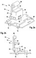
- Fig. 2a and 2b show an alternative embodiment in perspective view ( 2a ) or side view ( Fig. 2b ), in which an intended for targeted heat dissipation contact surface 20 is disposed on an outer side of a leg 22 of a heat sink 10.
- a first heat sink section 12 is designed as a spring in that the first heat sink section 12 is angled transversely, in particular vertically, from a second heat sink section 14.
- the second heat sink section 14 is plate-shaped and fixed to the circuit board 40 with fastening elements 16.
- the fastening of the second heat sink section 14 to the circuit board 40 can take place by means of a positive connection, in this case for example with so-called crimp feet as fastening elements 16, which engage in corresponding, unspecified recesses of the circuit board 40.
- the board For example, 40 may be connected to another circuit, not shown, or may be a section of a larger board.
- the component 42 between the contact surface 20 on the outside of one of the legs 18, 22 and a further clamping portion 34 can be clamped in the mounted state.
- the clamping portion 34 may be punched out of the second heat sink section 14 and bent accordingly.
- the first heat sink section 12 is configured such that the two legs 18, 22 are pressed against each other, wherein the legs 18, 22 strive apart. As a result, a spring force is exerted against the component 42, which counteracts the clamping portion 34 and thus presses the component 42 firmly against the outside of the second leg 22. Due to the intimate surface contact, a good heat transfer from the component 42 into the leg 22 and thus into the heat sink section 12 can take place.
- the component 42 is also held or guided here on the first heat sink section 12 by means of guide elements 30.
- the guide elements 30 are arranged laterally on the first leg 18, angled transversely to this and engage on side surfaces of the component 42.
- the component 42 may e.g. be a capacitor. Not shown is a variant in which other components, such. Field effect transistors, arranged on the outside of the leg 18 and / or 22 of the first heat sink portion 12, in particular screwed, can be.
Description
- Die Erfindung geht aus von einem Kühlkörper wenigstens eines elektrischen Bauteils nach dem Oberbegriff des Anspruchs 1.
- Es ist bekannt, Kühlkörper an elektrische Leistungsbauteile zu montieren, um eine ausreichende Wärmeabfuhr aus dem Leistungsbauteil zu gewährleisten. Typischerweise bestehen solche Kühlkörper aus einer Fläche, die einen großflächigen Kontakt zum Leistungsbauteil herstellt und quer davon abstehenden Finnen, welche die Oberfläche des Kühlkörpers effektiv vergrößern und die Wärmeabfuhr verbessern. Häufig wird der Kühlkörper mit dem Leistungsbauteil durch eine Wärmeleitpaste oder eine Vergussmasse verbunden. Bei Vibrationen oder starken Beschleunigungsschwankungen kann es zu einer Beschädigung des Leistungsbauteils kommen.
- Die
US 2004/206476 A1 zeigt einen Kühlkörper, bei dem ein Bauteil zwischen zwei Schenkel eines ersten Kühlkörperabschnitts des Kühlkörpers geklemmt werden kann, indem der Kühlkörper von oben über das Bauteil geschoben wird. Der Kühlkörper wird mit einem Kontaktpin an einer Platine festgelötet, der sich hinter den Kontaktpins des Bauteils befindet. Seitlich abgewinkelte Kühlkörperabschnitte dienen als zusätzliche Kühlfläche und stehen auf der Platine auf. - Die Erfindung geht aus von einem Kühlkörper wenigstens eines elektrischen Bauteils.
- Es wird vorgeschlagen, dass ein erster Kühlkörperabschnitt als Feder ausgebildet ist, wobei eine Kontaktfläche zwischen dem Kühlkörper und dem wenigstens einen Bauteil im ersten Kühlkörperabschnitt vorgesehen ist.
- Der erste Kühlkörperabschnitt ist quer zu einem zweiten Kühlkörperabschnitt abgewinkelt, wobei der zweite Kühlköperabschnitt im montierten Zustand zur Befestigung des Kühlkörpers an einer Platine vorgesehen ist. Der erste Kühlkörperabschnitt kann gegen den zweiten Kühlkörperabschnitt flexibel bewegt werden. Vibrationen können einfach abgefedert werden. Weiterhin ist der erste Kühlkörperabschnitt bügelförmig mit einem ersten Schenkel und einem zweiten Schenkel ausgebildet. Durch die bügelförmige Ausgestaltung kann eine vorteilhafte Federwirkung des Kühlkörpers unterstützt werden. Durch die Ausgestaltung kann ein sicheres und zuverlässiges flächiges Anliegen des Kühlkörpers an dem wenigstens einem Bauteil und damit sowohl eine sichere Fixierung des wenigstens einen Bauteils als auch eine zuverlässige Wärmeabfuhr sichergestellt werden. Es kann eine zuverlässige Verbindung mit dem wenigstens einen Bauteil hergestellt werden und eine vorteilhafte kompakte und schmale Bauform des Kühlkörpers erreicht werden.
- Vorteilhaft kann ein mit dem Kühlkörper am ersten Kühlkörperabschnitt verbundenes elektrisches Bauteil durch die Federwirkung des Kühlkörperabschnitts z.B. bei Vibrationen, Stoßeinwirkung oder Beschleunigungsschwankungen geschützt werden. So kann die Federwirkung des Kühlkörpers bei Deformationen z.B. nach starken Beschleunigungsschwankungen das elektrische Bauteil halten und wieder in die ursprüngliche Position zurückführen. Vorteilhaft kann der erste Kühlkörperabschnitt mit einem zweiten Kühlkörperabschnitt so verbunden sein, dass dieser erste Kühlkörperabschnitt z.B. federnd gegenüber dem zweiten Kühlkörperabschnitt auslenkbar ist. So kann der erste Kühlkörperabschnitt gegen den zweiten Kühlkörperabschnitt abgewinkelt oder mit einem Federelement verbunden sein. Ist der zweite Kühlkörperabschnitt starr fixiert, können Stöße oder Vibrationen durch den ersten Kühlkörperabschnitt abgefangen werden. Am Kühlkörper können auch mehrere zu kühlenden Bauteilen angeordnet sein, wobei wenigstens eines der Bauteile in der beschriebenen Weise mechanisch und hieraus resultierend thermisch angebunden ist.
- Gemäß einer bevorzugten Weiterbildung kann der zweite Kühlkörperabschnitt mit wenigstens einem Befestigungselement im montierten Zustand an einer Platine befestigbar sein. Vorzugsweise kann die Platine festgeklemmt sein. Somit kann vorteilhaft z.B. eine Schraubverbindung, die zusätzliche Befestigungselemente benötigt und zeitaufwändig herzustellen ist, vermieden werden. Das wenigstens eine Befestigungselement kann bevorzugt als Raste oder als Crimpfuß ausgebildet sein und in entsprechende Aussparungen in der Platine eingreifen. Dadurch kann ein mechanischer Halt des Kühlkörpers auf der Platine ohne zusätzliche Befestigungselemente erreicht werden. Ein solider Zusammenhalt von Platine und Kühlkörper kann mit und ohne zusätzliche Vergussmasse erreicht werden. Die Befestigung kann jedoch auch so erfolgen, dass die Platine am Kühlkörperabschnitt einschiebbar ist. Eine Fixierung gegen ein Verschieben kann beispielsweise durch eine Vergussmasse, die z.B. über der Verbindungsstelle Platine/Kühlkörperabschnitt angeordnet ist, sichergestellt werden.
- Vorteilhaft kann der erste Kühlkörperabschnitt am wenigstens einen Bauteil festklammerbar sein. Günstigerweise kann z.B. der erste Kühlkörperabschnitt zur Anlage an einer Hauptfläche des wenigstens einen Bauteils vorgesehen sein. Seitlich am Kühlkörperabschnitt können zwei Führungselemente ausgebildet sein, welche z.B. einander gegenüberliegende Seitenflächen des Bauteils fassen und z.B. der Führung des wenigstens einen Bauteils dienen.
- Gemäß einer zweckmäßigen Ausgestaltung kann die Kontaktfläche an einer Innenseite wenigstens eines der Schenkel angeordnet sein. Dann kann das wenigstens eine Bauteil in einem Hohlraum zwischen den Schenkeln angeordnet sein. Vorteilhaft kann das wenigstens eine Bauteil dabei zwischen dem ersten und dem zweiten Schenkel klemmbar sein. Die Wärmeübertragung kann durch die Klemmkraft der beiden Schenkel sichergestellt werden, und das wenigstens eine Bauteil kann sicher fixiert sein. Denkbar ist auch, dass weitere elektrische Bauteile an einem oder beiden Schenkeln befestigt, z.B. angeschraubt, sind. So kann etwa das zwischen den Schenkeln angeordnete Bauteil ein Kondensator sein, während auf der Außenseite eines oder beider Schenkel andere Komponenten, etwa Feldeffekttransistoren, angeordnet sein können.
- In einer alternativen Ausgestaltung kann die Kontaktfläche an einer Außenseite eines der Schenkel angeordnet sein. Die Wärmeübertragung kann durch eine Anpresskraft zwischen dem wenigstens einen Bauteil und Kühlkörper sichergestellt werden. Vorteilhaft kann im montierten Zustand das wenigstens eine Bauteil zwischen der Kontaktfläche an der Außenseite eines der Schenkel und einem weiteren Klemmabschnitt im Kühlkörper einklemmbar sein. Günstigerweise kann der Klemmabschnitt aus dem Kühlkörper gestanzt und passend umgebogen sein. Auch hier können weitere elektrische Bauteile an dem ersten Kühlköperabschnitt an dessen Außenseite angeordnet sein, z.B. an einer Außenseite angeschraubt sein.
- Insgesamt lässt sich der Kühlkörper preiswert als Stanzteil herstellen, bei dem der erste Kühlkörperabschnitt, die Führungselemente, Klemmelement und Befestigungselemente in geeigneter Weise abgewinkelt werden können. Die Montage des Kühlkörpers bzw. des Bauteils kann schnell und kostengünstig erfolgen.
- Weitere Vorteile ergeben sich aus der folgenden Zeichnungsbeschreibung. In der Zeichnung sind Ausführungsbeispiele der Erfindung dargestellt. Die Zeichnung, die Beschreibung und die Ansprüche enthalten zahlreiche Merkmale in Kombination. Der Fachmann wird die Merkmale zweckmäßigerweise auch einzeln betrachten und zu sinnvollen weiteren Kombinationen zusammenfassen.
- Es zeigen in schematischer Darstellung:
- Fig. 1 a, b
- eine bevorzugte Ausgestaltung eines Kühlkörpers mit einem elektrischen Bauteil, das in einem Kühlkörperabschnitt festgeklemmt ist in perspektivischer (
Fig. 1 a) und Seitenansicht (Fig. 1 c); und - Fig. 2a, b
- eine bevorzugte Ausgestaltung eines Kühlkörpers mit einem elektrischen Bauteil, das an einen Kühlkörperabschnitt angepresst ist in perspektivischer (
Fig. 2a ) und Seitenansicht (Fig. 2b ). - In den Figuren sind gleiche oder gleich wirkende Elemente mit denselben Bezugszeichen beziffert.
- Den
Fig. 1 a und 1 b ist eine erste bevorzugte Ausgestaltung eines Kühl körpers 10 in perspektivischer Ansicht (Fig.1a ) bzw. Seitenansicht (Fig. 1 b) zu entnehmen. Ein auf einer Platine 40 montiertes elektrisches Bauteil 42 ist mit dem Kühlkörper 10 zur Wärmeabfuhr verbunden. Im abgebildeten Ausführungsbeispiel ist ein erster Kühlkörperabschnitt 12 als Feder ausgebildet, indem der erste Kühlkörperabschnitt 12 von einem zweiten Kühlkörperabschnitt 14 quer, insbesondere senkrecht, abgewinkelt ist. Der zweite Kühlkörperabschnitt 14 ist plattenförmig ausgebildet und an der Platine 40 mit Befestigungselementen 16 festgelegt. - Vorteilhaft kann die Befestigung des zweiten Kühlkörperabschnitts 14 an der Platine 40 mittels einer formschlüssigen Verbindung erfolgen, hier z.B. mit so genannten Crimpfüßen als Befestigungselementen 16, die in entsprechende, nicht näher bezeichnete Aussparungen der Platine 40 eingreifen. Die Platine 40 kann z.B. mit einem weiteren, nicht dargestellten Schaltkreis verbunden sein oder ein Ausschnitt aus einer größeren Platine sein.
- Elektrische Kontakte des Bauteils 42 zur Platine 40 sind durch entsprechende Öffnungen 36 in dem zweiten Kühlkörperabschnitt 14 geführt. Das Bauteil 42 ist zur Wärmeabfuhr mechanisch mit dem ersten Kühlkörperabschnitt 12 verbunden. Das Bauteil 42 ist etwas von der Hauptfläche des zweiten Kühlkörperabschnitts 14 beabstandet und sitzt auf einem Höcker 32 des zweiten Kühlkörperabschnitts 14 auf.
- Der erste Kühlkörperabschnitt 12 ist bügelförmig ausgebildet und weist einen ersten Schenkel 18 und einen dazu parallelen zweiten Schenkel 22 auf, die mit einem Verbindungsstück 26 verbunden sind. Eine Kontaktfläche 20 zwischen dem Kühlkörper 10 und dem Bauteil 42, welche die gezielt als Wärmeableitfläche dient, ist im ersten Kühlkörperabschnitt 12 vorgesehen.
- Der erste Kühlkörperabschnitt 12 umfasst nicht näher bezeichnete Hauptflächen des Bauteils 42, wobei diese großflächig durch die Schenkel 18, 22 kontaktiert werden, indem die beiden Schenkel 18, 22 mit Klemmkraft das im Hohlraum 28 zwischen den Schenkeln 18, 22 angeordnete Bauteil 42 kontaktieren. Die Kontaktfläche 20 ist demgemäß an einer Innenseite des ersten Schenkels 18 angeordnet. Dort liegt der Schenkel 18 großflächig an dem Bauteil 42 an. Auf der gegenüberliegenden Seite liegt der zweite Schenkel 22 mit seinem gerundeten Endstück 24 an und drückt das Bauteil gegen den ersten Schenkel 18.
- Das Bauteil 42 kann mittels Führungselementen 30 geführt und gegebenenfalls sogar gehalten werden, welche am Kühlkörperabschnitt 12 angeordnet sind und quer von diesem abstehen. Die Führungselemente 30 sind seitlich am ersten Schenkel 18 angeordnet, greifen an Seitenflächen des Bauteils 42 an und dienen der Führung des Bauteils 42.
- Das Bauteil 42 kann z.B. ein Kondensator sein. Nicht dargestellt ist eine Variante, bei der weitere Bauteile, wie z.B. Feldeffekttransistoren, an der Außenseite des Schenkels 18 und/oder 22 des ersten Kühlkörperabschnitts 12 angeordnet, insbesondere angeschraubt, sein können.
-
Fig. 2a und 2b zeigen eine alternative Ausgestaltung in perspektivischer Ansicht (Fig.2a ) bzw. Seitenansicht (Fig. 2b ), bei der eine zur gezielten Wärmeabfuhr gedachte Kontaktfläche 20 an einer Außenseite eines Schenkels 22 eines Kühlkörpers 10 angeordnet ist. - Ein auf einer Platine 40 montiertes elektrisches Bauteil 42 ist mit dem Kühlkörper 10 zur Wärmeabfuhr verbunden. Ein erster Kühlkörperabschnitt 12 ist als Feder ausgebildet, indem der erste Kühlkörperabschnitt 12 von einem zweiten Kühlkörperabschnitt 14 quer, insbesondere senkrecht, abgewinkelt ist. Der zweite Kühlkörperabschnitt 14 ist plattenförmig ausgebildet und an der Platine 40 mit Befestigungselementen 16 festgelegt.
- Vorteilhaft kann die Befestigung des zweiten Kühlkörperabschnitts 14 an der Platine 40 mittels einer formschlüssigen Verbindung erfolgen, hier z.B. mit so genannten Crimpfüßen als Befestigungselementen 16, die in entsprechende, nicht näher bezeichnete Aussparungen der Platine 40 eingreifen. Die Platine 40 kann z.B. mit einem weiteren, nicht dargestellten Schaltkreis verbunden sein oder ein Ausschnitt aus einer größeren Platine sein.
- Im dargestellten Ausführungsbeispiel ist im montierten Zustand das Bauteil 42 zwischen der Kontaktfläche 20 an der Außenseite eines der Schenkel 18, 22 und einem weiteren Klemmabschnitt 34 einklemmbar. Der Klemmabschnitt 34 kann aus dem zweiten Kühlkörperabschnitt 14 ausgestanzt und entsprechend gebogen sein.
- Der erste Kühlkörperabschnitt 12 ist so ausgestaltet, dass die beiden Schenkel 18, 22 aneinander gepresst werden, wobei die Schenkel 18, 22 auseinander streben. Dadurch wird eine Federkraft gegen das Bauteil 42 ausgeübt, welcher der Klemmabschnitt 34 entgegenwirkt und so das Bauteil 42 fest gegen die Außenseite des zweiten Schenkels 22 presst. Durch den innigen flächigen Kontakt kann ein guter Wärmeübergang vom Bauteil 42 in den Schenkel 22 und damit in den Kühlkörperabschnitt 12 erfolgen.
- Das Bauteil 42 ist auch hier am ersten Kühlkörperabschnitt 12 mittels Führungselementen 30 gehalten bzw. geführt. Die Führungselemente 30 sind seitlich am ersten Schenkel 18 angeordnet, quer zu diesem abgewinkelt und greifen an Seitenflächen des Bauteils 42 an.
- Das Bauteil 42 kann z.B. ein Kondensator sein. Nicht dargestellt ist eine Variante, bei der weitere Bauteile, wie z.B. Feldeffekttransistoren, an der Außenseite des Schenkels 18 und/oder 22 des ersten Kühlkörperabschnitts 12 angeordnet, insbesondere angeschraubt, sein können.
Claims (9)
- Kühlkörper (10) wenigstens eines elektrischen Bauteils (42), wobei ein erster Kühlkörperabschnitt (12) als Feder ausgebildet ist, wo- wobei bei eine Kontaktfläche (20) zwischen dem Kühlkörper (10) und dem wenigstens einen Bauteil (42) am ersten Kühlkörperabschnitt (12) vorgesehen ist,- wobei der erste Kühlkörperabschnitt (12) quer zu einem zweiten Kühlkörperabschnitt (14) abgewinkelt ist,- der erste Kühlkörperabschnitt (12) bügelförmig mit einem ersten Schenkel (18) und einem zweiten Schenkel (22) ausgebildet ist und- wobei der erste Kühlkörperabschnitt (12) mit dem zweiten Kühlkörperabschnitt (14) so verbunden ist, dass der erste Kühlkörperabschnitt (12) federnd gegenüber dem zweiten Kühlkörperabschnitt (14) auslenkbar ist, dadurch gekennzeichnet, dass der zweite Kühlkörperabschnitt im montierten Zustand zur Befestigung des Kühlkörpers (10) an einer Platine (40) vorgesehen ist.
- Kühlkörper nach Anspruch 1, dadurch gekennzeichnet, dass der zweite Kühlkörperabschnitt (14) mit wenigstens einem Befestigungselement (16) im montierten Zustand an einer Platine (40) festklemmbar ist.
- Kühlkörper nach Anspruch 2, dadurch gekennzeichnet, dass das wenigstens eine Befestigungselement (16) als Crimpfuß ausgebildet ist.
- Kühlkörper nach einem der vorhergehenden Ansprüche, dadurch gekennzeichnet, dass der erste Kühlkörperabschnitt (12) Führungselemente (30) zum Führen des wenigstens einen Bauteils (42) aufweist.
- Kühlkörper nach einem der vorhergehenden Ansprüche, dadurch gekennzeichnet, dass die Kontaktfläche (20) an einer Innenseite wenigstens eines der Schenkel (18, 22) angeordnet ist.
- Kühlkörper nach Anspruch 5, dadurch gekennzeichnet, dass das wenigstens eine Bauteil (42) zwischen dem ersten und dem zweiten Schenkel (18, 22) klemmbar ist.
- Kühlkörper nach einem der Ansprüche 1 bis 4, dadurch gekennzeichnet, dass die Kontaktfläche (20) an einer Außenseite eines der Schenkel (18, 22) angeordnet ist.
- Kühlkörper nach Anspruch 6, dadurch gekennzeichnet, dass im montierten Zustand das wenigstens eine Bauteil (42) zwischen der Kontaktfläche (20) an der Außenseite eines der Schenkel (18, 22) und einem Klemmabschnitt (34) einklemmbar ist.
- Kühlkörper nach einem der vorhergehenden Ansprüche, dadurch gekennzeichnet, dass an einer oder mehreren Außenseiten des ersten Kühlkörperabschnitts (12) ein oder mehrere weitere elektrische Bauteile angeordnet sind.
Applications Claiming Priority (2)
| Application Number | Priority Date | Filing Date | Title |
|---|---|---|---|
| DE102007060249A DE102007060249A1 (de) | 2007-12-14 | 2007-12-14 | Kühlkörper wenigstens eines elektrischen Bauteils |
| PCT/EP2008/065301 WO2009077268A2 (de) | 2007-12-14 | 2008-11-11 | Kühlkörper wenigstens eines elektrischen bauteils |
Publications (2)
| Publication Number | Publication Date |
|---|---|
| EP2223334A2 EP2223334A2 (de) | 2010-09-01 |
| EP2223334B1 true EP2223334B1 (de) | 2016-01-27 |
Family
ID=40328457
Family Applications (1)
| Application Number | Title | Priority Date | Filing Date |
|---|---|---|---|
| EP08863100.7A Active EP2223334B1 (de) | 2007-12-14 | 2008-11-11 | Kühlkörper wenigstens eines elektrischen bauteils |
Country Status (5)
| Country | Link |
|---|---|
| US (1) | US8130498B2 (de) |
| EP (1) | EP2223334B1 (de) |
| CN (1) | CN101897020B (de) |
| DE (1) | DE102007060249A1 (de) |
| WO (1) | WO2009077268A2 (de) |
Families Citing this family (7)
| Publication number | Priority date | Publication date | Assignee | Title |
|---|---|---|---|---|
| DE102010043242A1 (de) * | 2010-11-03 | 2012-05-03 | Behr Gmbh & Co. Kg | Wärmeübertagungselement zur Wärmeleitung zwischen einer Oberfläche eines Wärmetauschers und auf dem Wärmetauscher angeordneten Festkörpern |
| DE102013006728A1 (de) * | 2013-04-19 | 2014-11-06 | Abb Ag | Elektronisches Unterputzgerät der Gebäude-Installationstechnik |
| US10497524B2 (en) | 2014-03-28 | 2019-12-03 | Black & Decker Inc. | Integrated electronic switch and control module for a power tool |
| DE102014109114B4 (de) * | 2014-06-30 | 2024-04-25 | HELLA GmbH & Co. KGaA | Anordnung eines Kühlkörpers in einem Scheinwerfer |
| DE102014212762A1 (de) * | 2014-07-02 | 2016-01-07 | Robert Bosch Gmbh | Befestigungseinrichtung, Gerät |
| US10541588B2 (en) | 2017-05-24 | 2020-01-21 | Black & Decker Inc. | Electronic power module for a power tool having an integrated heat sink |
| US10519992B2 (en) * | 2017-11-30 | 2019-12-31 | Ford Global Technologies, Llc | Spring clip with a single resilient cantilevered leg |
Family Cites Families (20)
| Publication number | Priority date | Publication date | Assignee | Title |
|---|---|---|---|---|
| US3572428A (en) * | 1969-01-29 | 1971-03-23 | Motorola Inc | Clamping heat sink |
| US4054901A (en) * | 1975-10-14 | 1977-10-18 | Thermalloy, Inc. | Index mounting unitary heat sink apparatus with apertured base |
| US4552206A (en) * | 1983-01-17 | 1985-11-12 | Aavid Engineering, Inc. | Heat sinks for integrated circuit modules |
| US4537246A (en) * | 1983-12-09 | 1985-08-27 | Conver Corporation | Vertical heat sink |
| JPH0432778Y2 (de) * | 1984-10-23 | 1992-08-06 | ||
| US4605058A (en) * | 1985-04-01 | 1986-08-12 | The Staver Company, Inc. | Heat dissipating retainer for electronic package |
| US4609040A (en) * | 1985-04-01 | 1986-09-02 | Thermalloy Incorporated | Self-securing heat sink |
| US4729426A (en) * | 1986-03-06 | 1988-03-08 | Thermalloy Incorporated | Bonded clip heat sink |
| US5019942A (en) * | 1987-11-30 | 1991-05-28 | Thermalloy Incorporated | Insulating apparatus for electronic device assemblies |
| US4872505A (en) * | 1988-08-16 | 1989-10-10 | Ncr Corporation | Heat sink for an electronic device |
| US4961125A (en) | 1989-08-18 | 1990-10-02 | Thermalloy Incorporated | Apparatus and method of attaching an electronic device package and a heat sink to a circuit board |
| US5068764A (en) | 1990-03-05 | 1991-11-26 | Thermalloy Incorporated | Electronic device package mounting assembly |
| US5040096A (en) * | 1990-06-07 | 1991-08-13 | Aavid Engineering, Inc. | High force clip |
| US5381041A (en) | 1994-04-05 | 1995-01-10 | Wakefield Engineering, Inc. | Self clamping heat sink |
| KR19990064171A (ko) * | 1995-10-13 | 1999-07-26 | 윌리암디.조단 | 접합식 트랜지스터 클립 및 열흡수 장치 |
| DE19723270A1 (de) * | 1997-06-03 | 1998-12-10 | Patent Treuhand Ges Fuer Elektrische Gluehlampen Mbh | Kühlblechverbindungsklammer für Leistungshalbleiter |
| FR2780456A1 (fr) | 1998-06-30 | 1999-12-31 | Valeo Electronique | Dispositif de blocage mecanique d'un element electrique ou electronique sur un support |
| WO2001062057A1 (en) * | 2000-02-17 | 2001-08-23 | Koninklijke Philips Electronics N.V. | Heat sink with an integrated component clamping device |
| US20040206476A1 (en) | 2003-04-16 | 2004-10-21 | Lee Hsaio Lung | Vertically mountable heat sink with solderable tab |
| DE102005002812B4 (de) | 2005-01-20 | 2013-07-18 | Infineon Technologies Ag | Kühlkörper für oberflächenmontierte Halbleiterbauteile und Montageverfahren |
-
2007
- 2007-12-14 DE DE102007060249A patent/DE102007060249A1/de not_active Withdrawn
-
2008
- 2008-11-11 CN CN2008801204189A patent/CN101897020B/zh active Active
- 2008-11-11 EP EP08863100.7A patent/EP2223334B1/de active Active
- 2008-11-11 US US12/808,061 patent/US8130498B2/en not_active Expired - Fee Related
- 2008-11-11 WO PCT/EP2008/065301 patent/WO2009077268A2/de active Application Filing
Also Published As
| Publication number | Publication date |
|---|---|
| US20100265661A1 (en) | 2010-10-21 |
| CN101897020B (zh) | 2012-12-26 |
| WO2009077268A3 (de) | 2009-08-20 |
| WO2009077268A2 (de) | 2009-06-25 |
| EP2223334A2 (de) | 2010-09-01 |
| US8130498B2 (en) | 2012-03-06 |
| CN101897020A (zh) | 2010-11-24 |
| DE102007060249A1 (de) | 2009-06-18 |
Similar Documents
| Publication | Publication Date | Title |
|---|---|---|
| EP2223334B1 (de) | Kühlkörper wenigstens eines elektrischen bauteils | |
| DE69632865T2 (de) | Transistor-lötclip und kühlkörper | |
| EP2316254B1 (de) | Elektronikmodul | |
| DE3612862A1 (de) | Kuehlkoerperbefestigungsanordnung fuer einen halbleiter | |
| WO2004109812A2 (de) | Gehäuse für ein strahlungsemittierendes bauelement, verfahren zu dessen herstellung und strahlungsemittierendes bauelement | |
| WO1997008750A1 (de) | Kühlkörper für elektronische bauelemente | |
| DE102009046489A1 (de) | Schutzeinrichtung für eine elektrische Schaltung | |
| DE112019002582T5 (de) | Schaltungsvorrichtung | |
| EP3226269B1 (de) | Leistungshalbleitereinrichtung | |
| DE102013101736A1 (de) | Anordnung zur Befestigung und Positionierung von Relais | |
| EP2489956B1 (de) | Kühleinrichtung eines elektrischen, sich erwärmenden Bauelements | |
| EP3565394A1 (de) | Elektronikeinheit | |
| EP3286803A1 (de) | Reihenklemme mit externem elektrischem bauelement | |
| DE10206271A1 (de) | Wärmeableitvorrichtung | |
| DE102020119128A1 (de) | Steckverbindermodul zum Anschließen einer Schutzleitung | |
| DE10246577A1 (de) | Leiterplatte mit Metallgehäuse | |
| EP2482386A1 (de) | Vorrichtung zur elektrischen und mechanischen Verbindung von zwei übereinander angeordneten Leiterplatten | |
| DE102012219145A1 (de) | Elektronikanordnung mit reduzierter Toleranzkette | |
| EP2586279B1 (de) | Elektronisches gerät mit gehäuse aus profilmaterial | |
| DE202014011393U1 (de) | Bauelement-Steckverbindungsanordnung zum steckbaren Verbinden eines Bauelements mit einer Leiterplatte | |
| DE102019121643B4 (de) | Klemme zur rückseitigen Befestigung an einem LED-Modul und Leuchtenanordnung mit Klemme | |
| DE102018111594B4 (de) | Leistungshalbleitermodul und Leistungshalbleitereinrichtung mit einem Leistungshalbleitermodul | |
| WO2016165902A1 (de) | Anbindung eines leistungsbauteils an einen kühlkörper | |
| DE102005036966A1 (de) | Elektrische Bauelementanordnung | |
| DE102011009440A1 (de) | Vorrichtung zur elektronischen und mechanischen Verbindung von zwei nebeneinander angeordneten Leiterplatten |
Legal Events
| Date | Code | Title | Description |
|---|---|---|---|
| PUAI | Public reference made under article 153(3) epc to a published international application that has entered the european phase |
Free format text: ORIGINAL CODE: 0009012 |
|
| 17P | Request for examination filed |
Effective date: 20100714 |
|
| AK | Designated contracting states |
Kind code of ref document: A2 Designated state(s): AT BE BG CH CY CZ DE DK EE ES FI FR GB GR HR HU IE IS IT LI LT LU LV MC MT NL NO PL PT RO SE SI SK TR |
|
| AX | Request for extension of the european patent |
Extension state: AL BA MK RS |
|
| DAX | Request for extension of the european patent (deleted) | ||
| GRAP | Despatch of communication of intention to grant a patent |
Free format text: ORIGINAL CODE: EPIDOSNIGR1 |
|
| INTG | Intention to grant announced |
Effective date: 20150917 |
|
| GRAS | Grant fee paid |
Free format text: ORIGINAL CODE: EPIDOSNIGR3 |
|
| GRAA | (expected) grant |
Free format text: ORIGINAL CODE: 0009210 |
|
| AK | Designated contracting states |
Kind code of ref document: B1 Designated state(s): AT BE BG CH CY CZ DE DK EE ES FI FR GB GR HR HU IE IS IT LI LT LU LV MC MT NL NO PL PT RO SE SI SK TR |
|
| REG | Reference to a national code |
Ref country code: GB Ref legal event code: FG4D Free format text: NOT ENGLISH |
|
| REG | Reference to a national code |
Ref country code: CH Ref legal event code: EP |
|
| REG | Reference to a national code |
Ref country code: AT Ref legal event code: REF Ref document number: 773061 Country of ref document: AT Kind code of ref document: T Effective date: 20160215 |
|
| REG | Reference to a national code |
Ref country code: IE Ref legal event code: FG4D Free format text: LANGUAGE OF EP DOCUMENT: GERMAN |
|
| REG | Reference to a national code |
Ref country code: DE Ref legal event code: R096 Ref document number: 502008013791 Country of ref document: DE |
|
| REG | Reference to a national code |
Ref country code: LT Ref legal event code: MG4D |
|
| REG | Reference to a national code |
Ref country code: NL Ref legal event code: MP Effective date: 20160127 |
|
| PG25 | Lapsed in a contracting state [announced via postgrant information from national office to epo] |
Ref country code: NL Free format text: LAPSE BECAUSE OF FAILURE TO SUBMIT A TRANSLATION OF THE DESCRIPTION OR TO PAY THE FEE WITHIN THE PRESCRIBED TIME-LIMIT Effective date: 20160127 |
|
| PG25 | Lapsed in a contracting state [announced via postgrant information from national office to epo] |
Ref country code: GR Free format text: LAPSE BECAUSE OF FAILURE TO SUBMIT A TRANSLATION OF THE DESCRIPTION OR TO PAY THE FEE WITHIN THE PRESCRIBED TIME-LIMIT Effective date: 20160428 Ref country code: FI Free format text: LAPSE BECAUSE OF FAILURE TO SUBMIT A TRANSLATION OF THE DESCRIPTION OR TO PAY THE FEE WITHIN THE PRESCRIBED TIME-LIMIT Effective date: 20160127 Ref country code: NO Free format text: LAPSE BECAUSE OF FAILURE TO SUBMIT A TRANSLATION OF THE DESCRIPTION OR TO PAY THE FEE WITHIN THE PRESCRIBED TIME-LIMIT Effective date: 20160427 Ref country code: HR Free format text: LAPSE BECAUSE OF FAILURE TO SUBMIT A TRANSLATION OF THE DESCRIPTION OR TO PAY THE FEE WITHIN THE PRESCRIBED TIME-LIMIT Effective date: 20160127 Ref country code: IT Free format text: LAPSE BECAUSE OF FAILURE TO SUBMIT A TRANSLATION OF THE DESCRIPTION OR TO PAY THE FEE WITHIN THE PRESCRIBED TIME-LIMIT Effective date: 20160127 Ref country code: ES Free format text: LAPSE BECAUSE OF FAILURE TO SUBMIT A TRANSLATION OF THE DESCRIPTION OR TO PAY THE FEE WITHIN THE PRESCRIBED TIME-LIMIT Effective date: 20160127 |
|
| PG25 | Lapsed in a contracting state [announced via postgrant information from national office to epo] |
Ref country code: LV Free format text: LAPSE BECAUSE OF FAILURE TO SUBMIT A TRANSLATION OF THE DESCRIPTION OR TO PAY THE FEE WITHIN THE PRESCRIBED TIME-LIMIT Effective date: 20160127 Ref country code: PT Free format text: LAPSE BECAUSE OF FAILURE TO SUBMIT A TRANSLATION OF THE DESCRIPTION OR TO PAY THE FEE WITHIN THE PRESCRIBED TIME-LIMIT Effective date: 20160527 Ref country code: PL Free format text: LAPSE BECAUSE OF FAILURE TO SUBMIT A TRANSLATION OF THE DESCRIPTION OR TO PAY THE FEE WITHIN THE PRESCRIBED TIME-LIMIT Effective date: 20160127 Ref country code: LT Free format text: LAPSE BECAUSE OF FAILURE TO SUBMIT A TRANSLATION OF THE DESCRIPTION OR TO PAY THE FEE WITHIN THE PRESCRIBED TIME-LIMIT Effective date: 20160127 Ref country code: SE Free format text: LAPSE BECAUSE OF FAILURE TO SUBMIT A TRANSLATION OF THE DESCRIPTION OR TO PAY THE FEE WITHIN THE PRESCRIBED TIME-LIMIT Effective date: 20160127 Ref country code: IS Free format text: LAPSE BECAUSE OF FAILURE TO SUBMIT A TRANSLATION OF THE DESCRIPTION OR TO PAY THE FEE WITHIN THE PRESCRIBED TIME-LIMIT Effective date: 20160527 |
|
| REG | Reference to a national code |
Ref country code: DE Ref legal event code: R097 Ref document number: 502008013791 Country of ref document: DE |
|
| PG25 | Lapsed in a contracting state [announced via postgrant information from national office to epo] |
Ref country code: EE Free format text: LAPSE BECAUSE OF FAILURE TO SUBMIT A TRANSLATION OF THE DESCRIPTION OR TO PAY THE FEE WITHIN THE PRESCRIBED TIME-LIMIT Effective date: 20160127 Ref country code: DK Free format text: LAPSE BECAUSE OF FAILURE TO SUBMIT A TRANSLATION OF THE DESCRIPTION OR TO PAY THE FEE WITHIN THE PRESCRIBED TIME-LIMIT Effective date: 20160127 |
|
| PG25 | Lapsed in a contracting state [announced via postgrant information from national office to epo] |
Ref country code: SK Free format text: LAPSE BECAUSE OF FAILURE TO SUBMIT A TRANSLATION OF THE DESCRIPTION OR TO PAY THE FEE WITHIN THE PRESCRIBED TIME-LIMIT Effective date: 20160127 Ref country code: CZ Free format text: LAPSE BECAUSE OF FAILURE TO SUBMIT A TRANSLATION OF THE DESCRIPTION OR TO PAY THE FEE WITHIN THE PRESCRIBED TIME-LIMIT Effective date: 20160127 Ref country code: RO Free format text: LAPSE BECAUSE OF FAILURE TO SUBMIT A TRANSLATION OF THE DESCRIPTION OR TO PAY THE FEE WITHIN THE PRESCRIBED TIME-LIMIT Effective date: 20160127 |
|
| PLBE | No opposition filed within time limit |
Free format text: ORIGINAL CODE: 0009261 |
|
| STAA | Information on the status of an ep patent application or granted ep patent |
Free format text: STATUS: NO OPPOSITION FILED WITHIN TIME LIMIT |
|
| 26N | No opposition filed |
Effective date: 20161028 |
|
| PG25 | Lapsed in a contracting state [announced via postgrant information from national office to epo] |
Ref country code: BG Free format text: LAPSE BECAUSE OF FAILURE TO SUBMIT A TRANSLATION OF THE DESCRIPTION OR TO PAY THE FEE WITHIN THE PRESCRIBED TIME-LIMIT Effective date: 20160427 Ref country code: SI Free format text: LAPSE BECAUSE OF FAILURE TO SUBMIT A TRANSLATION OF THE DESCRIPTION OR TO PAY THE FEE WITHIN THE PRESCRIBED TIME-LIMIT Effective date: 20160127 Ref country code: BE Free format text: LAPSE BECAUSE OF NON-PAYMENT OF DUE FEES Effective date: 20161130 |
|
| REG | Reference to a national code |
Ref country code: CH Ref legal event code: PL |
|
| PG25 | Lapsed in a contracting state [announced via postgrant information from national office to epo] |
Ref country code: CH Free format text: LAPSE BECAUSE OF NON-PAYMENT OF DUE FEES Effective date: 20161130 Ref country code: LI Free format text: LAPSE BECAUSE OF NON-PAYMENT OF DUE FEES Effective date: 20161130 |
|
| REG | Reference to a national code |
Ref country code: IE Ref legal event code: MM4A |
|
| REG | Reference to a national code |
Ref country code: FR Ref legal event code: ST Effective date: 20170731 |
|
| PG25 | Lapsed in a contracting state [announced via postgrant information from national office to epo] |
Ref country code: LU Free format text: LAPSE BECAUSE OF NON-PAYMENT OF DUE FEES Effective date: 20161130 |
|
| PG25 | Lapsed in a contracting state [announced via postgrant information from national office to epo] |
Ref country code: FR Free format text: LAPSE BECAUSE OF NON-PAYMENT OF DUE FEES Effective date: 20161130 |
|
| PG25 | Lapsed in a contracting state [announced via postgrant information from national office to epo] |
Ref country code: IE Free format text: LAPSE BECAUSE OF NON-PAYMENT OF DUE FEES Effective date: 20161111 |
|
| REG | Reference to a national code |
Ref country code: AT Ref legal event code: MM01 Ref document number: 773061 Country of ref document: AT Kind code of ref document: T Effective date: 20161111 |
|
| PG25 | Lapsed in a contracting state [announced via postgrant information from national office to epo] |
Ref country code: AT Free format text: LAPSE BECAUSE OF NON-PAYMENT OF DUE FEES Effective date: 20161111 |
|
| REG | Reference to a national code |
Ref country code: BE Ref legal event code: MM Effective date: 20161130 |
|
| PG25 | Lapsed in a contracting state [announced via postgrant information from national office to epo] |
Ref country code: CY Free format text: LAPSE BECAUSE OF FAILURE TO SUBMIT A TRANSLATION OF THE DESCRIPTION OR TO PAY THE FEE WITHIN THE PRESCRIBED TIME-LIMIT Effective date: 20160127 Ref country code: HU Free format text: LAPSE BECAUSE OF FAILURE TO SUBMIT A TRANSLATION OF THE DESCRIPTION OR TO PAY THE FEE WITHIN THE PRESCRIBED TIME-LIMIT; INVALID AB INITIO Effective date: 20081111 |
|
| PG25 | Lapsed in a contracting state [announced via postgrant information from national office to epo] |
Ref country code: TR Free format text: LAPSE BECAUSE OF FAILURE TO SUBMIT A TRANSLATION OF THE DESCRIPTION OR TO PAY THE FEE WITHIN THE PRESCRIBED TIME-LIMIT Effective date: 20160127 Ref country code: MC Free format text: LAPSE BECAUSE OF FAILURE TO SUBMIT A TRANSLATION OF THE DESCRIPTION OR TO PAY THE FEE WITHIN THE PRESCRIBED TIME-LIMIT Effective date: 20160127 |
|
| PG25 | Lapsed in a contracting state [announced via postgrant information from national office to epo] |
Ref country code: MT Free format text: LAPSE BECAUSE OF FAILURE TO SUBMIT A TRANSLATION OF THE DESCRIPTION OR TO PAY THE FEE WITHIN THE PRESCRIBED TIME-LIMIT Effective date: 20160127 |
|
| PGFP | Annual fee paid to national office [announced via postgrant information from national office to epo] |
Ref country code: DE Payment date: 20230124 Year of fee payment: 15 |
|
| PGFP | Annual fee paid to national office [announced via postgrant information from national office to epo] |
Ref country code: GB Payment date: 20231123 Year of fee payment: 16 |