EP2203137B1 - Closed incision negative pressure wound therapy device - Google Patents
Closed incision negative pressure wound therapy device Download PDFInfo
- Publication number
- EP2203137B1 EP2203137B1 EP08836852.7A EP08836852A EP2203137B1 EP 2203137 B1 EP2203137 B1 EP 2203137B1 EP 08836852 A EP08836852 A EP 08836852A EP 2203137 B1 EP2203137 B1 EP 2203137B1
- Authority
- EP
- European Patent Office
- Prior art keywords
- collection chamber
- wound
- sealant layer
- incision
- layer
- Prior art date
- Legal status (The legal status is an assumption and is not a legal conclusion. Google has not performed a legal analysis and makes no representation as to the accuracy of the status listed.)
- Revoked
Links
- 238000009581 negative-pressure wound therapy Methods 0.000 title description 2
- 239000000565 sealant Substances 0.000 claims description 148
- 206010052428 Wound Diseases 0.000 claims description 120
- 208000027418 Wounds and injury Diseases 0.000 claims description 118
- 208000014674 injury Diseases 0.000 claims description 91
- 230000008733 trauma Effects 0.000 claims description 91
- 239000012530 fluid Substances 0.000 claims description 41
- 238000004891 communication Methods 0.000 claims description 39
- 239000012298 atmosphere Substances 0.000 claims description 2
- 229920001195 polyisoprene Polymers 0.000 claims description 2
- 229920002379 silicone rubber Polymers 0.000 claims description 2
- 239000004945 silicone rubber Substances 0.000 claims description 2
- 239000010410 layer Substances 0.000 description 203
- 238000002560 therapeutic procedure Methods 0.000 description 40
- 208000002847 Surgical Wound Diseases 0.000 description 28
- 239000000463 material Substances 0.000 description 26
- 239000011241 protective layer Substances 0.000 description 25
- 238000000034 method Methods 0.000 description 20
- 230000007246 mechanism Effects 0.000 description 17
- 239000000853 adhesive Substances 0.000 description 15
- 230000001070 adhesive effect Effects 0.000 description 15
- 230000009977 dual effect Effects 0.000 description 11
- 210000001519 tissue Anatomy 0.000 description 11
- 238000007789 sealing Methods 0.000 description 10
- 239000006260 foam Substances 0.000 description 7
- 230000035876 healing Effects 0.000 description 7
- 206010048038 Wound infection Diseases 0.000 description 6
- 230000008878 coupling Effects 0.000 description 6
- 238000010168 coupling process Methods 0.000 description 6
- 238000005859 coupling reaction Methods 0.000 description 6
- 238000005520 cutting process Methods 0.000 description 6
- 210000000416 exudates and transudate Anatomy 0.000 description 6
- 230000001105 regulatory effect Effects 0.000 description 6
- 239000004599 antimicrobial Substances 0.000 description 5
- 230000000295 complement effect Effects 0.000 description 5
- 230000002745 absorbent Effects 0.000 description 4
- 239000002250 absorbent Substances 0.000 description 4
- 239000003242 anti bacterial agent Substances 0.000 description 4
- 229940088710 antibiotic agent Drugs 0.000 description 4
- 239000003795 chemical substances by application Substances 0.000 description 4
- 238000009826 distribution Methods 0.000 description 4
- 230000004044 response Effects 0.000 description 4
- 238000000926 separation method Methods 0.000 description 4
- 239000011324 bead Substances 0.000 description 3
- 230000015572 biosynthetic process Effects 0.000 description 3
- 239000011248 coating agent Substances 0.000 description 3
- 238000000576 coating method Methods 0.000 description 3
- 229940124447 delivery agent Drugs 0.000 description 3
- 239000000416 hydrocolloid Substances 0.000 description 3
- 208000015181 infectious disease Diseases 0.000 description 3
- 230000009467 reduction Effects 0.000 description 3
- 238000004513 sizing Methods 0.000 description 3
- 230000003068 static effect Effects 0.000 description 3
- 230000029663 wound healing Effects 0.000 description 3
- 241000894006 Bacteria Species 0.000 description 2
- GHXZTYHSJHQHIJ-UHFFFAOYSA-N Chlorhexidine Chemical compound C=1C=C(Cl)C=CC=1NC(N)=NC(N)=NCCCCCCN=C(N)N=C(N)NC1=CC=C(Cl)C=C1 GHXZTYHSJHQHIJ-UHFFFAOYSA-N 0.000 description 2
- 208000034693 Laceration Diseases 0.000 description 2
- 206010030113 Oedema Diseases 0.000 description 2
- 230000003213 activating effect Effects 0.000 description 2
- 230000008859 change Effects 0.000 description 2
- 229960003260 chlorhexidine Drugs 0.000 description 2
- 230000008602 contraction Effects 0.000 description 2
- 238000013461 design Methods 0.000 description 2
- 230000000694 effects Effects 0.000 description 2
- 239000013013 elastic material Substances 0.000 description 2
- 239000003292 glue Substances 0.000 description 2
- 239000011159 matrix material Substances 0.000 description 2
- 239000004033 plastic Substances 0.000 description 2
- 230000037390 scarring Effects 0.000 description 2
- 229910001316 Ag alloy Inorganic materials 0.000 description 1
- 229920000742 Cotton Polymers 0.000 description 1
- 206010051425 Enterocutaneous fistula Diseases 0.000 description 1
- JOYRKODLDBILNP-UHFFFAOYSA-N Ethyl urethane Chemical compound CCOC(N)=O JOYRKODLDBILNP-UHFFFAOYSA-N 0.000 description 1
- 206010061218 Inflammation Diseases 0.000 description 1
- 208000008081 Intestinal Fistula Diseases 0.000 description 1
- 241000405070 Percophidae Species 0.000 description 1
- 206010036410 Postoperative wound infection Diseases 0.000 description 1
- 239000004820 Pressure-sensitive adhesive Substances 0.000 description 1
- BQCADISMDOOEFD-UHFFFAOYSA-N Silver Chemical compound [Ag] BQCADISMDOOEFD-UHFFFAOYSA-N 0.000 description 1
- 208000031650 Surgical Wound Infection Diseases 0.000 description 1
- 206010048031 Wound dehiscence Diseases 0.000 description 1
- 238000012084 abdominal surgery Methods 0.000 description 1
- 239000012790 adhesive layer Substances 0.000 description 1
- QVGXLLKOCUKJST-UHFFFAOYSA-N atomic oxygen Chemical compound [O] QVGXLLKOCUKJST-UHFFFAOYSA-N 0.000 description 1
- 230000003190 augmentative effect Effects 0.000 description 1
- 230000001580 bacterial effect Effects 0.000 description 1
- 238000005452 bending Methods 0.000 description 1
- 230000003115 biocidal effect Effects 0.000 description 1
- 239000000560 biocompatible material Substances 0.000 description 1
- 239000003124 biologic agent Substances 0.000 description 1
- 230000017531 blood circulation Effects 0.000 description 1
- 230000012292 cell migration Effects 0.000 description 1
- 230000006835 compression Effects 0.000 description 1
- 238000007906 compression Methods 0.000 description 1
- 210000002808 connective tissue Anatomy 0.000 description 1
- 230000003111 delayed effect Effects 0.000 description 1
- 238000006073 displacement reaction Methods 0.000 description 1
- 230000002500 effect on skin Effects 0.000 description 1
- 239000013536 elastomeric material Substances 0.000 description 1
- 230000003898 enterocutaneous fistula Effects 0.000 description 1
- 239000003102 growth factor Substances 0.000 description 1
- 238000003306 harvesting Methods 0.000 description 1
- 210000002865 immune cell Anatomy 0.000 description 1
- 230000036737 immune function Effects 0.000 description 1
- 230000028993 immune response Effects 0.000 description 1
- 230000037189 immune system physiology Effects 0.000 description 1
- 238000007373 indentation Methods 0.000 description 1
- 230000008595 infiltration Effects 0.000 description 1
- 238000001764 infiltration Methods 0.000 description 1
- 230000004054 inflammatory process Effects 0.000 description 1
- PNDPGZBMCMUPRI-UHFFFAOYSA-N iodine Chemical compound II PNDPGZBMCMUPRI-UHFFFAOYSA-N 0.000 description 1
- 230000002262 irrigation Effects 0.000 description 1
- 238000003973 irrigation Methods 0.000 description 1
- 238000002350 laparotomy Methods 0.000 description 1
- 230000033001 locomotion Effects 0.000 description 1
- 238000002803 maceration Methods 0.000 description 1
- 238000004519 manufacturing process Methods 0.000 description 1
- 235000015097 nutrients Nutrition 0.000 description 1
- 229910052760 oxygen Inorganic materials 0.000 description 1
- 239000001301 oxygen Substances 0.000 description 1
- 206010033675 panniculitis Diseases 0.000 description 1
- 239000013618 particulate matter Substances 0.000 description 1
- 230000000149 penetrating effect Effects 0.000 description 1
- 230000035515 penetration Effects 0.000 description 1
- 230000010412 perfusion Effects 0.000 description 1
- 230000002093 peripheral effect Effects 0.000 description 1
- 239000002831 pharmacologic agent Substances 0.000 description 1
- 230000000144 pharmacologic effect Effects 0.000 description 1
- 229920001296 polysiloxane Polymers 0.000 description 1
- 239000011148 porous material Substances 0.000 description 1
- 230000002980 postoperative effect Effects 0.000 description 1
- 230000008569 process Effects 0.000 description 1
- 230000002035 prolonged effect Effects 0.000 description 1
- 230000000069 prophylactic effect Effects 0.000 description 1
- 238000011471 prostatectomy Methods 0.000 description 1
- 230000002787 reinforcement Effects 0.000 description 1
- 230000011218 segmentation Effects 0.000 description 1
- 229910052709 silver Inorganic materials 0.000 description 1
- 239000004332 silver Substances 0.000 description 1
- 239000002356 single layer Substances 0.000 description 1
- 210000004304 subcutaneous tissue Anatomy 0.000 description 1
- 238000001356 surgical procedure Methods 0.000 description 1
- 229920001169 thermoplastic Polymers 0.000 description 1
- 239000004416 thermosoftening plastic Substances 0.000 description 1
- 230000001052 transient effect Effects 0.000 description 1
- 239000012780 transparent material Substances 0.000 description 1
- 230000000472 traumatic effect Effects 0.000 description 1
- 210000003462 vein Anatomy 0.000 description 1
- 238000012800 visualization Methods 0.000 description 1
- XLYOFNOQVPJJNP-UHFFFAOYSA-N water Chemical compound O XLYOFNOQVPJJNP-UHFFFAOYSA-N 0.000 description 1
Images


Classifications
-
- A—HUMAN NECESSITIES
- A61—MEDICAL OR VETERINARY SCIENCE; HYGIENE
- A61M—DEVICES FOR INTRODUCING MEDIA INTO, OR ONTO, THE BODY; DEVICES FOR TRANSDUCING BODY MEDIA OR FOR TAKING MEDIA FROM THE BODY; DEVICES FOR PRODUCING OR ENDING SLEEP OR STUPOR
- A61M1/00—Suction or pumping devices for medical purposes; Devices for carrying-off, for treatment of, or for carrying-over, body-liquids; Drainage systems
- A61M1/90—Negative pressure wound therapy devices, i.e. devices for applying suction to a wound to promote healing, e.g. including a vacuum dressing
- A61M1/91—Suction aspects of the dressing
- A61M1/915—Constructional details of the pressure distribution manifold
-
- A—HUMAN NECESSITIES
- A61—MEDICAL OR VETERINARY SCIENCE; HYGIENE
- A61F—FILTERS IMPLANTABLE INTO BLOOD VESSELS; PROSTHESES; DEVICES PROVIDING PATENCY TO, OR PREVENTING COLLAPSING OF, TUBULAR STRUCTURES OF THE BODY, e.g. STENTS; ORTHOPAEDIC, NURSING OR CONTRACEPTIVE DEVICES; FOMENTATION; TREATMENT OR PROTECTION OF EYES OR EARS; BANDAGES, DRESSINGS OR ABSORBENT PADS; FIRST-AID KITS
- A61F13/00—Bandages or dressings; Absorbent pads
- A61F13/00051—Accessories for dressings
- A61F13/00063—Accessories for dressings comprising medicaments or additives, e.g. odor control, PH control, debriding, antimicrobic
-
- A—HUMAN NECESSITIES
- A61—MEDICAL OR VETERINARY SCIENCE; HYGIENE
- A61F—FILTERS IMPLANTABLE INTO BLOOD VESSELS; PROSTHESES; DEVICES PROVIDING PATENCY TO, OR PREVENTING COLLAPSING OF, TUBULAR STRUCTURES OF THE BODY, e.g. STENTS; ORTHOPAEDIC, NURSING OR CONTRACEPTIVE DEVICES; FOMENTATION; TREATMENT OR PROTECTION OF EYES OR EARS; BANDAGES, DRESSINGS OR ABSORBENT PADS; FIRST-AID KITS
- A61F13/00—Bandages or dressings; Absorbent pads
- A61F13/02—Adhesive plasters or dressings
- A61F13/0203—Adhesive plasters or dressings having a fluid handling member
- A61F13/0226—Adhesive plasters or dressings having a fluid handling member characterised by the support layer
-
- A—HUMAN NECESSITIES
- A61—MEDICAL OR VETERINARY SCIENCE; HYGIENE
- A61F—FILTERS IMPLANTABLE INTO BLOOD VESSELS; PROSTHESES; DEVICES PROVIDING PATENCY TO, OR PREVENTING COLLAPSING OF, TUBULAR STRUCTURES OF THE BODY, e.g. STENTS; ORTHOPAEDIC, NURSING OR CONTRACEPTIVE DEVICES; FOMENTATION; TREATMENT OR PROTECTION OF EYES OR EARS; BANDAGES, DRESSINGS OR ABSORBENT PADS; FIRST-AID KITS
- A61F13/00—Bandages or dressings; Absorbent pads
- A61F13/02—Adhesive plasters or dressings
- A61F13/0259—Adhesive plasters or dressings characterised by the release liner covering the skin adhering layer
- A61F13/0266—Adhesive plasters or dressings characterised by the release liner covering the skin adhering layer especially adapted for wound covering/occlusive dressings
-
- A61F13/05—
-
- A—HUMAN NECESSITIES
- A61—MEDICAL OR VETERINARY SCIENCE; HYGIENE
- A61M—DEVICES FOR INTRODUCING MEDIA INTO, OR ONTO, THE BODY; DEVICES FOR TRANSDUCING BODY MEDIA OR FOR TAKING MEDIA FROM THE BODY; DEVICES FOR PRODUCING OR ENDING SLEEP OR STUPOR
- A61M27/00—Drainage appliance for wounds or the like, i.e. wound drains, implanted drains
-
- A—HUMAN NECESSITIES
- A61—MEDICAL OR VETERINARY SCIENCE; HYGIENE
- A61F—FILTERS IMPLANTABLE INTO BLOOD VESSELS; PROSTHESES; DEVICES PROVIDING PATENCY TO, OR PREVENTING COLLAPSING OF, TUBULAR STRUCTURES OF THE BODY, e.g. STENTS; ORTHOPAEDIC, NURSING OR CONTRACEPTIVE DEVICES; FOMENTATION; TREATMENT OR PROTECTION OF EYES OR EARS; BANDAGES, DRESSINGS OR ABSORBENT PADS; FIRST-AID KITS
- A61F13/00—Bandages or dressings; Absorbent pads
- A61F2013/00089—Wound bandages
- A61F2013/0017—Wound bandages possibility of applying fluid
- A61F2013/00174—Wound bandages possibility of applying fluid possibility of applying pressure
-
- A—HUMAN NECESSITIES
- A61—MEDICAL OR VETERINARY SCIENCE; HYGIENE
- A61F—FILTERS IMPLANTABLE INTO BLOOD VESSELS; PROSTHESES; DEVICES PROVIDING PATENCY TO, OR PREVENTING COLLAPSING OF, TUBULAR STRUCTURES OF THE BODY, e.g. STENTS; ORTHOPAEDIC, NURSING OR CONTRACEPTIVE DEVICES; FOMENTATION; TREATMENT OR PROTECTION OF EYES OR EARS; BANDAGES, DRESSINGS OR ABSORBENT PADS; FIRST-AID KITS
- A61F13/00—Bandages or dressings; Absorbent pads
- A61F2013/00361—Plasters
- A61F2013/00365—Plasters use
- A61F2013/00536—Plasters use for draining or irrigating wounds
-
- A—HUMAN NECESSITIES
- A61—MEDICAL OR VETERINARY SCIENCE; HYGIENE
- A61M—DEVICES FOR INTRODUCING MEDIA INTO, OR ONTO, THE BODY; DEVICES FOR TRANSDUCING BODY MEDIA OR FOR TAKING MEDIA FROM THE BODY; DEVICES FOR PRODUCING OR ENDING SLEEP OR STUPOR
- A61M1/00—Suction or pumping devices for medical purposes; Devices for carrying-off, for treatment of, or for carrying-over, body-liquids; Drainage systems
- A61M1/90—Negative pressure wound therapy devices, i.e. devices for applying suction to a wound to promote healing, e.g. including a vacuum dressing
- A61M1/98—Containers specifically adapted for negative pressure wound therapy
- A61M1/984—Containers specifically adapted for negative pressure wound therapy portable on the body
- A61M1/985—Containers specifically adapted for negative pressure wound therapy portable on the body the dressing itself forming the collection container
Description
- There are millions of closed incisions (surgical or non surgical) each year, that occur in settings ranging from office-based procedures and ambulatory surgical centers to traditional in-patient hospital settings. Post-procedural care of these incisions may vary, but can involve simple use of gauze, wraps and tapes. In addition, irrigation of the wound prior to closure and meticulous sterile technique has also been advocated. Wound infections following invasive procedures and surgeries presents a potential risk to patients that can be as high as 10% with abdominal surgeries, for example. Wound infections are a significant morbidity for patients, clinicians, and hospitals and can be costly to taxpayers and other payors. Patients with wound infections may need IV antibiotics, prolonged hospitalization, wound opening and dressing changes, and some go on to develop wound dehiscence and enterocutaneous fistulas. While pre-operative prophylactic antibiotics have been shown to decrease post-operative wound infection, post-operative antibiotics have not.
WO 2008/100437 andWO 2008/048527 describe reduced pressure treatment systems for wounds. These documents are not relevant for the assessment of inventive step.US 2007/185426 ,WO 2007/092397 ,US 2007/225663 ,US 2005/070835 , andUS 2005/131327 describe reduced pressure wound dressings. - Provided herein is a wound treatment device according to claim 1.
- In some embodiments, the device may comprise a contact layer. The contact layer may be adapted and configured to be in communication with the collection chamber of the device. In some embodiments, the contact layer has a conduit or opening that permits fluid communication with the collection chamber.
- The device may comprise a protective layer. The protective layer may be used to affix the contact layer to the surgically closed area of skin trauma. Where a protective layer is used, the protective layer may be further adapted and configured to protect the skin adjacent to the surgically closed area of skin trauma.
- Also provided herein is a closed incision therapy device, comprising a collection chamber. The collection chamber may be in a pre-evacuated state before the collection chamber is used with the device. In some disclosures, the collection chamber is deformable or bendable by the user or healthcare provider. In a further disclosure, the collection chamber comprises a flexible tube. The flexible tube may be configured to deform or bend in response to changes in the surface topology of the surgically closed area of skin trauma.
- In a further disclosure of the device described herein, the collection chamber comprises a flexible tube with discrete collection members for collecting exudate or other suitable material. In some disclosures, the flexible tube comprises a single discrete collection member, but in other disclosures, the flexible tube comprises two or more discrete collection members. At least one of the discrete collection chambers may be in communication with the flexible tubing. For example, the discrete collection members may be in fluid communication with the flexible tubing. Where at least two discrete collection members are used, the discrete collection members may be in communication with other discrete collection members and may be separated by a segment of flexible tubing. Two or more of the discrete collection members may be in fluid communication with each other. In some disclosures, the flexible tubing and the discrete collection members are adapted and configured to be integrated with the sealant layer, while in other disclosures, the discrete collection members but not the flexible tubing are adapted and configured to be integrated with the sealant layer. The collection chamber may comprise a series of openings. In such a disclosure, the series of openings are adapted and configured to provide fluid communication between the collection chamber and the surgically closed area of skin trauma.
- In some embodiments, the collection chamber comprises a support integrated into the walls of the collection chamber. The support structure may be adapted and configured to allow the user to shape the collection chamber into a particular configuration. The support structure may further maintain or resist changes to the shape of the particular configuration, or at least until a new configuration is desired by the user.
- The collection chamber preferably comprises a one-way flow valve. In some disclosures, the one way flow valve is adapted and configured to facilitate the emptying of the collection chamber. The one-way flow valve may be further adapted and configured to facilitate the re-creation of a reduced level of pressure inside the collection chamber and/or to restore the collection chamber to its original pre-evacuated state.
- The collection chamber may be a dual chamber collection chamber. For example, the dual chamber collection chamber may comprise a first chamber and a second chamber, where the first and second chamber are in communication with each other. The second chamber may further comprise an actuating and/or regulating mechanism. The actuating and/or regulating mechanism may be a non-powered or passive actuating mechanism. In such a disclosure, the second chamber is adapted and configured to expand a volume of air located in a joint volume of space shared between the sealed enclosure and the dual chamber collection chamber. In some disclosures, the dual chamber collection chamber comprises a reciprocating mechanism.
- As mentioned above, the device may further comprise a contact layer. The contact layer may serve as a vehicle for the delivery of one or more agents that augment the healing process. In some embodiments, the agents may include a pharmacological or biological agent. In some embodiments, the contact layer is a porous dressing interface.
- A wound treatment device may be adapted and configured to conform to the length of the surgically closed area of skin trauma. The wound treatment device may be cut to size. In some examples, the collection chamber of the wound treatment device is adapted and configured to conform to the length of the surgically closed area of skin trauma. In other examples, the contact layer and/or the sealant layer may be configured to conform to the length of the surgically closed area of skin trauma. In some embodiments, the sealant layer may be configured to be semi-rigid. In such an embodiment, the sealant layer may be configured to provide tensile support to the surgically closed area of skin trauma. In such an embodiment, the sealant layer may be adapted to alleviate mechanical tension.
- The device may further comprise absorbent beads or other absorbent structures. The device may further comprise antimicrobial agents. In some disclosures, the device is configured to be emptied and further configured to be re-evacuated. In some embodiments, the device is configured to deliver reduced pressure between about 0.001 to about 1 atmosphere. In some embodiments the level of atmospheric pressure underneath the sealant layer may be reduced to about 0.001 atm or higher, but in other embodiments to about 0.005 atm, about 0.01 atm, about 0.05 atm, about 0.1 atm, about 0.2 atm, about 0.5 atm, about 0.7 atm, or about 0.9 atm. In some embodiments, the atmospheric pressure underneath the sealant layer is reduced to less than about 0.8 atm, about 0.7 atm, about 0.6 atm, about 0.4 atm, about 0.3 atm, about 0.2 atm, about 0.1 atm, about 0.07 atm, about 0.03 atm, about 0.007 atm, or even to less than about 0.003 atm.
- In some disclosures of the device provided herein, the contact layer, the sealant layer, and/or the collection chamber are further configured to be translucent or transparent so as to facilitate application to the incision site.
- In another disclosure, a wound treatment device is provided, wherein the wound treatment device comprises a flexible sealant structure with an upper surface, a lower surface and an adhesive, a collection structure integrally formed with the flexible sealant structure and comprising a wall and an internal space surrounded by the wall, and a plurality of passageways between the internal space of the collection structure and the lower surface of the flexible sealant structure and passing through the wall of the collection structure and through the upper surface of the flexible sealant structure. In some examples, there are at least three passageways. Also, in some examples the device further comprises a suction source and/or a suction port in fluid communication with the internal space of the collection structure. The suction source may comprise a constant force spring and/or a sliding seal. In some instances, the suction source has a fixed external profile independent of its internal pressure level. In some specific examples, the suction source may be integrally formed with the collection structure. In regards to the collection structures, the collection structure may be a collection tube comprising a first end and a second end, and the plurality of passageways may be longitudinally spaced between the first and the second end of the collection tube. In some instances, the collection structure may be a flexible collection structure.
- A method for treating a closed incision is described, where the method or procedure comprises forming a sealed space along a closed incision using a sealant layer, wherein the closed incision was formed by wound edges previously attached to each other and reducing pressure in the sealed space. The method may also further comprise mechanically pushing the wound edges against each other using the sealant layer, contracting the sealant layer onto a support structure, and/or reducing tissue tension variations along the sealed space. The closed incision may be any of a variety of closed incisions, including but not limited to those closed with sutures or staples. The sutured incisions may be interrupted sutures, running or continuous sutures, and the like.
- Further described herein is a method of applying reduced pressure therapy to a surgically closed area of skin trauma, comprising (a) sizing a collection chamber, a protective layer and a sealant layer to a size of the surgically closed area of skin trauma, (b) forming a seal around said the surgically closed area of skin trauma, (c) activating said collection chamber to deliver reduced pressure to the surgically closed area of skin trauma, and (d) removing the device after at least some re-epithelialization of the surgically closed area of skin trauma. The method further describes a collection chamber wherein the reduced pressure is distributed through the surgically closed area of skin trauma.
- A method for treating a surgically closed area of skin trauma using a reduced pressure therapy device is described comprising the steps of (a) cutting a flexible protective layer to the shape of an area of skin trauma, (b) attaching the cut protective layer to an area of intact skin surrounding the area of skin trauma, (c) cutting a flexible adhesive dressing with an integrated layer of foam to a desired size, said flexible adhesive dressing integrated with said layer of foam in fluid communication with a flexible tubing, (d) placing the dressing over said surgically closed area of skin trauma to form a sealed enclosure, (e) configuring the tubing with an end piece, (f) charging the device, (g) recharging the device as necessary to remove exudates and to restore reduced pressure inside said enclosure, and (h) removing the device after at least some wound re-epithelialization. The method for treating a surgically closed area of skin trauma includes trauma selected from a cut, puncture wound, surgical incision, and any combination thereof.
- The features of the invention are set forth with particularity in the appended claims. A better understanding of the features and advantages of the present invention will be obtained by reference to the following detailed description that sets forth illustrative embodiments, in which the principles of the invention are utilized, and the accompanying drawings of which:
-
Figures 1A and 1B depict one embodiment of a negative pressure therapy device as viewed from the top and from the side perspective. -
Figure 2 depicts an embodiment of a negative pressure therapy device as viewed from above in which the device is designed to be emptied and re-evacuated. -
Figure 3 depicts an embodiment of the negative pressure therapy device as viewed from above in which the collection chamber is a segmented collection chamber. -
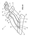
Figure 4 depicts an embodiment of the negative pressure therapy device in which an occlusive layer is placed over the collection chamber. -
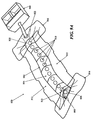
Figure 5 depicts an embodiment of the negative pressure therapy device in which the collection chamber comprises corrugated tubing segments interspersed with discrete collection members. -
Figure 6A is a perspective view of another embodiment of a negative pressure therapy device;Figure 6B and 6C are axial cross-sectional views of the device inFigure 6A , before and after the application of reduced pressure, respectively. -
Figure 7 is a schematic perspective view of two wound coverings joined together. -
Figure 8 depicts another embodiment of the negative pressure therapy device, comprising a split support. -
Figure 9A is a perspective view of another embodiment of a negative pressure therapy device comprising an elastic collection channel;Figures 9B to 9D are schematic cross-sectional views of the device inFigure 9A before, during and after stretching, respectively;Figure 9E is a schematic perspective view of two negative pressure therapy devices joined together. -
Figures 10A to 10C are schematic cross-sectional views of another negative pressure therapy device with reinforced apertures, before, during and after stretching, respectively. -
Figures 11A to 11C are schematic cross-sectional views of another negative pressure therapy device comprising an open longitudinal channel, before, during and after stretching, respectively. -
Figure 12 is a schematic illustration of an elongate negative pressure therapy system arranged around a perimeter of a wound. -
Figure 13 is schematic illustration of an elongate negative pressure therapy system arranged in a spiral orientation about a wound. -
Figure 14 is schematic illustration of an elongate negative pressure therapy system arranged in a zig-zag orientation about a wound. -
Figures 15 is schematic illustration of an elongate negative pressure therapy system arranged in a T-orientation about a wound. - Infections of surgical incisions and other wounds may result from bacterial growth that occurs in small pockets of fluid collections that may form within the subcutaneous tissues. These small fluid collections lack blood flow and thus may provide inadequate immune function or antibiotic penetration to prevent or treat infection. Once contaminated with bacteria, there can be unfettered growth in these areas. Thus, by reducing the formation of these fluid collections, the risk of a wound infection may be reduced. Although some closure techniques utilize dermal or deep sutures to reduce the formation of these fluid pockets, these sutures may also act as foreign bodies that may increase the risk of wound infection. Furthermore, improper suturing technique may still leave significant dead space under the skin that allows for fluid to collect and eventually become contaminated by bacteria. In addition to wound infection, wound healing may inhibited by excessive tension on the wound. Excessive tension may result from sutures or other wound closure devices that exert focal forces on portions of the incision or wound, and may also lead to increased scarring.
- Studies have also demonstrated that a moist wound healing environment may promote more rapid re-epithelialization of wounds by facilitating cell migration toward the wound center, in contrast to current gauze dressings that create a dry wound environment. Moreover, surgical and other wounds undergo of immune cell infiltration, inflammation and subsequent edema. The immune response may be an integral process of wound healing, but the ensuing edema may also be an impediment to healing. Finally, proper healing requires oxygen and nutrients which require adequate perfusion to the incision site which may be impeded by some of the immunological processes.
- In one example, a negative or reduced pressure wound therapy system may be used to treat of areas of skin trauma that have been surgically closed, or other types of elongate lacerations or wounds. The negative pressure wound therapy system may comprise a sealant layer and a collection chamber. The sealant layer may be designed such that it can form a seal around a surgically closed area of skin trauma, such as the surgical incision, and form a sealed enclosure or space. In some examples, the sealant layer may comprise a single piece or body, while in other examples, the sealant layer may comprise multiple pieces that may be applied together to form an enclosed space or area. The sealant layer may also comprise a single layer of material, or multiple layers of materials. The seal may be sufficiently air tight so that the pressure in the sealed enclosure or space may be reduced and maintained at a reduced level. The negative pressure therapy system may also comprise a collection chamber that is configured to distribute the reduced pressure applied to the surgically closed incision site along the length of the incision or wound. The negative pressure therapy system may also be used to treat a surgical incision left open to heal by secondary intention, or by delayed primary closure (i.e. third intention). The system may comprise a collection chamber in continuity to a surgical incision that is sealed in a closed system as created by a sealant layer. The collection chamber, when activated, may generate a negative pressure at the surgical incision site to promote healing, remove exudate, and/or reduce infection rates, for example. In some particular examples, the system provided herein may have an elongate configuration and may be sized or configured to conform to the length of the surgical incision. The collection chamber may be integrally formed or pre-attached to a sealant layer, or the collection chamber and the sealant layer may be configured to permit the collection chamber to be positioned under the sealant layer.
- In some embodiments, the system further comprises a suction apparatus. When the suction apparatus is used with the system, the suction apparatus may be configured to be in communication with the sealed enclosure or space. The suction apparatus, together with the sealant layer and collection chamber, may form a closed system for treating a surgical incision or other type of wound. The suction apparatus, when engaged, may be used to reduce the level of pressure located inside the sealed enclosure by forcefully expanding the volume of air located within the sealed enclosure. The suction source may be a closed or open system. For example, the suction apparatus may be a syringe, a powered pump, a Venturi system, a forced expansion device, constant force spring device, or a static negative pressure device, or any suitable active or passive suction source. In some embodiments, the suction source may be integrally formed with the collection chamber. In some embodiments, the suction source is connected to the collection chamber through the use of an extension tube.
- In some embodiments, the system further comprises a contact layer. The contact layer may be configured to permit fluid communication with the collection chamber. The contact layer may be placed in contact with the surface of the surgically closed area of skin trauma. In some embodiments, the contact layer may only be in contact with the surgically closed area of skin trauma and may not be in contact with the area surrounding the site of trauma. In other embodiments, the contact layer may be in contact with both the area of skin trauma and the area surrounding the area of skin trauma. The contact layer may facilitate the continuity of fluid communication between the collection chamber and the surgical area of skin trauma. In some examples, the contact layer may comprise a porous material or other structure comprising air spaces, including, but not limited to, foam, a stacked mesh matrix, gauze, cotton, a sponge, or any known suitable material in the art. In some embodiments where the contact layer is used, the contact layer may serve as a delivery vehicle for delivery agents. The delivery agents may include, but are not limited to, growth factors, antibiotics, antimicrobial agents, or any suitable delivery agent. In some embodiments, the agents used to improve healing are integrated with the contact layer. In some embodiments, the agents used are integrated or located with the collection chamber.
- In some embodiments, the system further comprises a protective layer. A protective layer may be used to surround the surgical area of skin trauma. For example, the protective layer may be attached or adhered to the area of skin surround the area of skin trauma. A pressure sensitive adhesive on the underside of the protective layer may provide the attachment or adherence properties to the skin. A protective layer may also be used to form a seal in combination with a sealant layer. The seal is airtight, or may be semi-permeable or impermeable to water vapor. In some embodiments, the protective layer may be sized to the surgical area of skin trauma such that it fits around the area of skin trauma. In some examples, the protective layer may be cut to size, but in other embodiments, the protective layer may comprise perforations or other pre-defined separation structures to facilitate the sizing. In certain embodiments, the protective layer may have a thin central peel-away strip or layer that may be removed after the protective layer has been placed around the area of skin trauma. In such embodiments, a wider contact layer may be placed over the protective layer. The protective layer may be used to affix the contact layer to the surgical area of skin trauma, and may protect the underlying skin or tissue from trauma associated with removal of the contact layer to access the surgical site. The protective layer can be any known material suitable for protecting the skin surrounding the skin trauma from maceration. The protective layer may comprise any of a variety of foam and/or hydrocolloid materials, including Duoderm® wound care products.
- The collection chamber of the static negative pressure therapy system may be configured to distribute the pressure levels applied to the incision site over the length of the surgically closed area of trauma. In some embodiments, the collection chamber may be in a pre-evacuated state prior to being placed on the surgically closed incision area of skin trauma. In such an embodiment, the collection chamber, once in communication with the area of skin trauma, can then be activated to apply reduced pressure to the area of skin trauma. In some examples, the collection chamber comprises a tubular structure. The tubular structure may comprise a rigid tube, for example, a moldable or flexible tube. The tube may comprise a deformable or elastic support that permit the tube to be bent or shaped into a particular configuration while also allowing the tube to holding or biasing the tube in that configuration. For example, the support structure may comprise a wire mesh cage or frame surrounding the tube, coupled to the inner lumen of the tube, or otherwise supporting the tube. In some embodiments, the tube has a wire support structure integrally within the walls of the tube. The support structure may also comprise a moldable plastic material, or the tubing itself may comprise a moldable plastic including. Moldable materials include, but are not limited to, thermoplastics, elastomeric materials, or any suitable moldable material. In some embodiments, the collection chamber may be configured for single use only, while in other embodiments, the collection chamber may be emptied and re-evacuated during use.
- In some embodiments, the collection chamber is a flexible tube which comprises one or more corrugated sections. In such an embodiment, the corrugated tubing section may be flexible and can conform to the surface topology of the surgically closed area of skin trauma. The corrugated tubing sections may allow the flexible tubing to conform to the two-dimensional or three-dimension configuration of the wound or incision and allows the tubing to passively adjust in response to changes in the wound configuration as the patient moves or as the wound heals. In some embodiments, the flexible tube may comprise entirely of corrugated tubing, while in other embodiments, the flexible tubing is corrugated tubing sections with discrete collection members or non-corrugated sections located therebetween. In one embodiment, the non-corrugated sections may be rigid, or may be semi-rigid or flexible but with less flexibility than the corrugated sections. Some embodiments may comprise at least one non-corrugated section located within the tubing, while other embodiments may comprise two or more non-corrugated sections located along the tubing. The tubular segments may be connected by corrugated tubes that provide fluid communication along a length of the tubing and/or provide flexibility to the tubing such that the entire collection chamber structure, the rigid non-corrugated sections and the flexible corrugated tubing sections overall permit conformation to the skin or surgical site as it moves. Sometimes, flexible tubing may mitigate the discomfort to the patient or reduce the localized pressure points from the treatment system. In some embodiments comprising both rigid collection sections and flexible sections along the collection chamber, both the flexible tubing segments and the rigid collection sections may be embedded into the sealant layer, coupled to the sealant layer, or integrally formed with the sealant layer. In some embodiments, only the discrete collection members are coupled or embedded into the sealant layer, while the flexible tubing segments are not.
- Some embodiments of the system comprise a collection chamber and a sealant layer, where the sealant layer and the collection chamber are in fluid communication with an area of skin trauma. Fluid communication may be provided by a series of openings in the sealant layer and the collection chamber which provide fluid communication between the area of skin trauma and the collection chamber. The openings may be located longitudinally oriented along a length of the collection chamber, with corresponding openings of the sealant layer aligned with the openings in the collection chamber. Fluid, or any other suitable matter, may then be drawn up from the surgically closed area of skin trauma into the collection chamber. When an optional contact layer is employed, the fluid may passes first through the contact layer, and then through the holes connecting the sealant layer and collection chamber. In addition, the series of openings located throughout the collection chamber may allow for the distribution of pressure to the area of skin trauma and reduce or prevent areas of localized pressure or fluid build-up that may be greater in some areas and less in other areas.
- In some embodiments, the collection chamber further comprises a one-way flow valve. The one-way flow valve may be used to assist in the emptying of the collection chamber. The one-way flow valve may also be used to re-create the reduced pressure, or pre-evacuated, level of pressure inside the collection chamber. In some embodiments, the one-way flow valve may be used to facilitate both empting of the collection chamber and re-evacuation of the collection chamber. The one-way flow valve may serves to facilitate the re-evacuation of the collection chamber by facilitating the attachment of a suction source to the collection chamber through the valve and allowing the suction source to remove air molecules from the collection chamber. The suction source may also be used to remove exudate or air from the collection chamber through the use of the one-way flow valve. In some embodiments, a first one-way flow valve is used to empty the collection chamber and a second one-way flow valve is used to re-evacuate the collection chamber. In some embodiments, the one-way flow valve may be integrated with the collection chamber. In some embodiments, the one-way flow valve is attached to a removable plug used to occlude one end of the collection chamber. In some embodiments, a plurality of one-way valves may be provided, with one or more valves located in or associated with the series of openings to reduce backflow of air or material out of the collection chamber or the sealant layer and back into the area of skin trauma. The one-way valves may have any of a variety of configurations, including duckbill or flap valves.
- A segmented collection device or other multi-cavity device may be used in place of a single chamber collection chamber in some embodiments. A segmented collection chamber may comprise a first chamber and a second chamber which may or may not be in fluid communication with each other. In one example, the first chamber is in direct communication with the sealant layer whereas the second chamber is in communication with the first chamber. In embodiments where a dual chamber collection chamber is used, one or more of the segments or chambers may be a source of suction. The suction source may comprise a non-powered or passive actuating and regulating mechanism, including but not limited to a spring mechanism such as a constant force spring. The passive actuating and regulating mechanism may be used to apply and maintain a level of pressure inside the sealed enclosure or space between the collection chamber and the sealant layer. In some embodiments, the dual chamber collection chamber comprises a reciprocating mechanism including, but not limited to, a plunger. The plunger may be manually distracted, or may be passively distracted, such as when attached to a constant force spring. In some embodiments, the second chamber expands the volume of air located in a joint volume of space shared between the sealed enclosure and the dual chamber collection chamber. One or segments or chambers may also comprise a powered or active actuating and regulating mechanism.
- In some embodiments, the system may also be sized or configured to conform to the length of the surgically closed incision. In some embodiments, the collection chamber conforms to the length of the closed incision area of skin trauma by being stretched to the length of the wound. In such an embodiment, the collection can be made from a hydrocolloid material. Such a material allows the collection chamber to be stretched to a new desired length and remain at that length after the stress causing the change in length has been removed. In such an embodiment, the system may be made from a hydrocolloid or any suitable material. In some embodiments, the system may be shortened to the length of the closed incision. In some embodiments, the system can be cut to the length of the closed area of skin trauma. In such an embodiment, the cut end of the collection chamber may be self sealing upon the application of pressure to the collection chamber. In some embodiments, the collection chamber can be sealed after it has been cut. In some embodiments, the collection chamber can be sealed with an end cap, a plug, an occlusive sealant sheet, an end cap with a one way flow valve, a constant force spring, a reduced pressure system, or any suitable means for sealing the end of the collection chamber. In one embodiment, the structure used to seal the end of the collection chamber that has been adjusted to conform to the length of the skin trauma is configured to resist removal once affixed to the collection chamber. Alternatively, the structure used to seal the end of the collection chamber that has been adjusted to conform to the length of the skin trauma may be a removable structure. In some embodiments, the system includes a series of collection chambers lined up in parallel or serially with each other. In such an embodiment, one or more collection chambers may be removed from the series of collection chambers to accommodate the width of the closed incision area of skin trauma. In other embodiments, one or more collection chambers may be replaced upon filling or clogging.
- In some embodiments, the contact layer may be adjusted to conform to the length of the surgically closed area of skin trauma. For example, the contact layer may be lengthened or shortened based upon the length of the closed incision or wound. In some embodiments, the contact layer may be cut to the length of the closed incision. In some embodiments, the collection chamber, the contact layer, and/or the sealant layer may be adjusted to conform to the length of the surgically closed incision. In some embodiments, only the collection chamber is adjusted to conform to the length of the incision before the system is placed on the patient, while in other embodiments, only the contact layer or the sealant layer is adjusted to conform to the length of the surgical incision before the system is placed on the patient. In some embodiments, the collection chamber, the contact layer, and the sealant layer may each be individually adjusted to conform to the length of the incision or wound before being placed on the patient. In some embodiments, the collection chamber, the contact layer, and the sealant layer are integrated together, such that the system is adjusted to conform to the length of the surgically closed incision or wound as a unit.
- The system provided herein includes a sealant layer for creating a seal with the surface of the patient. In some embodiments, the seal is air tight. In some embodiments, the sealant layer comprises a flexible impermeable material. In some embodiments the sealant layer is a semi-rigid material. In an embodiment where the sealant layer is a semi-rigid material, the sealant layer may provide tensile support to the surgically closed area of skin trauma. A semi-rigid sealant layer would further alleviate mechanical tension on the surgically closed area of skin trauma as the trauma heals.
- In some embodiments, the system provided for herein further includes absorbent beads. The absorbent beads are located in the incision or wound, and/or the collection chamber. In some embodiments, the system may comprise antimicrobial agents. Antimicrobial agents include, but are not limited to, silver, iodine, chlorhexidine or any other suitable antimicrobial agent.
- Some of the examples provided herein are configured to create a level of pressure within the sealed enclosure encompassing the surgically closed area of skin trauma. In some embodiments, the level of pressure created is between about 0.001 and about 1 atm. When in fluid communication with the enclosed space under the sealant layer, the level of atmospheric pressure underneath the sealant layer may be reduced to no lower than about 0.001 atm, about 0.005 atm, about 0.01 atm, about 0.05 atm, about 0.1 atm, about 0.2 atm, about 0.5 atm, about 0.7 atm, or about 0.9 atm. In other embodiments, the atmospheric pressure underneath the sealant layer may be reduced to about 0.8 atm or less, but in other embodiments, may be reduced to less than about 0.7 atm, 0.6 atm, about 0.4 atm, about 0.3 atm, about 0.2 atm, about 0.1 atm, about 0.07 atm, about 0.03 atm, about 0.007 atm, or to about 0.003 atm or less.
- In some embodiments, the contact layer, the sealant layer and/or the collection chamber may be made from transparent materials. The transparency of the materials may facilitate more accurate placement of the system over the surgical incision or wound by the clinician to more accurately place the system, and/or may permit visualization of the incision or wound with breaking the seal.
- Also described herein is a method for applying a reduced pressure therapy system to a surgically closed area of skin trauma. The method comprises (a) sizing a collection chamber, a protective layer and a sealant layer to a surgically closed area of skin trauma; (b) forming a seal around the surgically closed area of skin trauma; (c) activating the collection chamber to deliver reduced pressure evenly distributed to the surgically closed area of skin trauma; and (d) removing the system after re-epithelialization of the surgically closed area of skin trauma. Wound re-epithelialization occurs between 2 days and 5 days after the skin trauma has been surgically closed. In some examples wound re-epithelialization occurs 3 days after closure. In some examples wound re-epithelialization occurs 4 days after closure. In some examples wound re-epithelialization occurs 5 days after closure. In some examples, wound re-epithelialization occurs earlier than 5 days after wound closure. In some examples, wound re-epithelialization occurs earlier than 4 days after wound closure. In some examples, wound re-epithelialization occurs earlier than 3 days following wound closure.
- Further described is a method for treating an area of skin trauma using a reduced pressure therapy system, comprising: (a) cutting a protective layer to the shape of an area of skin trauma; (b) attaching the cut protective layer to an area of intact skin surrounding the area of skin trauma; (c) cutting a flexible adhesive dressing with an integrated layer of foam to a desired size, said flexible adhesive dressing integrated with said layer of foam in fluid communication with a flexible tubing; (d) placing the dressing over said surgically closed area of skin trauma to form a sealed enclosure; (e) configuring the tubing with an end piece; (f) charging the device; (g) recharging the device as necessary to remove exudates and to restore reduced pressure inside said enclosure; and (h) removing the device after wound re-epithelialization. In some examples the skin trauma is selected from a cut, puncture wound, surgically created incision, or any other wound which is suitable for being closed surgically.
-
Figs. 1A and 1B illustrate one embodiment staticnegative pressure device 100. Thedevice 100 comprises asealant layer 110 and acollection chamber 120 configured to distribute pressure along a surgical area of skin trauma, such as the length of a surgical incision. In some embodiments, the negative pressure therapy device may include acontact layer 130. Thecontact layer 130 provides fluid communication between thecollection chamber 120 and the area of skin trauma. Thecontact layer 130 may comprise a foam, mesh, gauze, sponge, particulate matter, a stacked mesh matrix, or any other suitable porous biocompatible material, for example. Thecontact layer 130 may be put into contact with the surface of the surgically closed area of skin trauma. In some instances, thecontact layer 130 may be configured to maintain continuity of the air/fluid spaces through the surgical site, which may reduce the occurrence of isolated fluid or air pockets in the enclosed space formed by the surgical area and thesealant layer 110. In some embodiments, the contact layer may be within the borders the skin trauma surface and not contact, overlap or cover the surrounding tissue area adjacent to the skin trauma. In other embodiments, the contact layer may be placed in contact with the adjacent tissue surrounding the skin trauma, in addition to the region of skin trauma itself. As shown inFig. 1A , thecontact layer 130, thesealant layer 110, and thecollection chamber 120 may be coupled or integrated together. In some examples, a pre-coupled or integrated design may permit thedevice 100 to be placed in contact with the skin trauma surface in one step. In some embodiments, the contact layer is placed in contact with the skin trauma surface. Once positioned, the contact layer is then covered by the sealant layer with an integrated collection chamber to form a sealed enclosure or space. In some embodiments, the sealant layer may be affixed to the area of skin surrounding the trauma area by any suitable materials or mechanisms known to one skilled in the art, including but not limited to, tape, glue, or a suitable biocompatible adhesive product. - Further depicted in
Fig. 1A is one example of asuction apparatus 140. Thesuction apparatus 140 may be configured to create a level of reduced pressure inside of thecollection chamber 120. In some embodiments, thecollection chamber 120 may be in a pre-evacuated state prior to being positioned on the surface of the skin trauma, while in other embodiments, thecollection chamber 120 may be evacuated after positioning, or after coupling to thesuction apparatus 140. Thecollection chamber 120 may be pre-evacuated at the point-of-use or at the point-of-manufacture. In some embodiments, the suction apparatus may be coupled to the collection chamber prior to being positioned on the surface of the skin trauma, and in still other embodiments, the suction apparatus and the collection chamber may be integrally formed. In some embodiments the collection chamber may be sized to the length of the surgically closed area of skin trauma by cutting the collection chamber or by detaching or one or more portions of the collection chamber. In some configurations, the collection chamber may have one or more pre-defined separation zones with reduced thickness to facilitate length reductions. A suction apparatus can then be attached or otherwise used to close the cut or separated end of the collection chamber.Fig 1A shows thedevice 100 with acollection chamber 120 in which asuction apparatus 140 comprises with a constantforce spring mechanism 142 has been integrated with thecollection chamber 120. When the constantforce spring mechanism 142 of thesuction apparatus 140 is engaged, the slidable seal orreciprocating mechanism 144 may be drawn back to create and maintain a constant level of pressure inside the sealed enclosure. InFig. 1A , thedevice 100 has been sized to the length of a wound by cutting one end 122 of thecollection chamber 120.Fig 1A further depicts the non-suction apparatus end 122 being occluded by anend plug 124. The device is further sealed inFig. 1A using anend sealant structure 126. The non-suction apparatus end 122 and/or theend plug 124 may be configured to detachable or non-detachable. For example, a glue may be used to irreversibly attach the end plug to the apparatus end 122. - In some embodiments, the length of the collection chamber may be adjusted based upon the length of the surgical incision or wound. The length of the surgical incision or wound may be generally linear or may be non-linear. In some examples, the length of the collection chamber is about the length of the surgical wound, while in other examples, the collection chamber length may be about +10%, about +20%, about +30% or more, about -10%, about-20%, or about -30% or less than the length of the surgical wound. Although generally elongate surgical wounds are contemplated, in other examples, surgical wounds with non-elongate configuration may also be treated. In some further examples, branching or stellate surgical wounds may be treated, using one or more devices. In other examples, the surgical wound or incision may be characterized as the affected length of a partially dehisced surgical wound. In examples where the surgical wound comprises a partially dehisced surgical incision, the sealant layer and/or contact layer may be configured to seal or cover the dehisced segment, or the entire wound or incision. Exemplary methods for treating non-elongate wounds are described later below. In some examples, the collection chamber per cm length, may have a volume in the range of about 100 mm3 to about 10,000 mm3 or more, sometimes about 500 mm3 to about 7,000 mm3, and other times about 1,000 mm3 to about 5,000 mm3.
- The
collection chamber 120 may be in fluid communication with the skin trauma site through thecontact layer 130 of thedevice 100. In some examples, thecollection chamber 120 and thesealant layer 110 are integrally formed. As depicted inFig. 1B , thecollection chamber 120 may comprise a plurality ofopenings 150 that may align or correspond to a plurality of openings 150' in thesealant layer 110 to provide fluid communication between the skin trauma andcollection chamber 120 through thecontact layer 130 and thesealant layer 110. The series ofopenings 150 and 150' may permit distribution of the pressure changes applied to the area of skin trauma across the length or region of the skin trauma. The spacing, size or shape of theopenings 150 and 150' along thecollection chamber 120 and/or thesealant layer 110 may be uniform or non-uniform. In other embodiments, thecollection chamber 120 and thesealant layer 110 may comprise separate structures that are configured for coupling. To facilitate alignment of thecollection chamber openings 150 with the openings of thesealant layer 110, the adjacent surface of thecollection chamber 150 and/or thesealant layer 110 may comprise an adhesive or slip-resistant surface. In other embodiments, thecollection chamber openings 150 and/or openings in thesealant layer 120 may form complementary interfit to facilitate alignment. For example, thecollection chamber openings 150 and/or the sealant layer openings 150'may protrude into the opening in the corresponding structure. In still other embodiments, thecollection chamber openings 150 and the sealant layer openings 150' may comprise complementary sealable snapfit. - In some examples, the collection chamber may comprise an elastically or plastically deformable material or a bendable configuration. This may permit the collection chamber to conform to the contours of a surgically closed area of skin trauma, and may permit the collection chamber to exhibit at least some conformational change in response to body movement. In one example depicted in
Figs. 1A and 1B , thecollection chamber 120 comprises regions or zones offlexible ribbing 128 along the length of thecollection chamber 120. Theribbing 128 allows thecollection chamber 120 to be shaped and molded by the user and further maintains the user defined configuration. The portions of thecollection chamber 120 between theflexible ribbing 128 may be rigid, semi-rigid or flexible. In some further examples, a collection chamber may also be configured to at least partially rotate in addition to bending. In certain examples, different sizes or configurations of openings may be provided around the circumference of the collection chamber and may be selected for use by rotation. The unused opening may be sealed by applying a sealant layer over the unused openings. Alternatively, the openings may be presealed and the selected seals may be utilized by removing the pre-attached seal(s) from them. -
Fig. 2 shows another embodiment of a negativepressure therapy device 200 in which thedevice 200 is configured to be re-evacuated or recharged. Thedevice 200 comprises anintegrated contact layer 230,sealant layer 210 and collection chamber 220. Thecontact layer 230 may be placed in contact with the surface of the skin trauma and a seal may be formed between the skin surrounding the skin trauma using thesealant layer 210. The collection chamber 220 may be integrated with thesealant layer 210 and is in fluid communication with the contact layer and the enclosed surgical site through a series ofopenings 250 in the collection chamber 220 and thecontact layer 230, but in other examples, the collection chamber and the sealant layer may be separated components that may be attached using adhesive or mechanical mechanisms. With separate collection chambers and sealant layers, the alignment of the collection chamber openings and the sealant layer openings may be facilitated by configuring either the collection chamber openings and/or the sealant layer openings with complementary interfit designs. In one alternative embodiment, the base sealant layer may lack pre-formed openings, but the collection chamber openings may comprise sharpened or penetrating structures to permit formation of sealant layer openings when the two components are coupled together. - The collection chamber 220 may be in a pre-evacuated state wherein a level of reduced pressure is already present inside. Alternatively, the collection chamber 220 can be at atmospheric pressure when placed on the patient, and a reduced level of pressure can be created in the collection chamber using an
external evacuator device 270, such as a durable medical equipment evacuator. Theexternal evacuator device 270 may be positioned in anopening 276 of an evacuator fitting 278 on the collection chamber 220. Theevacuator fitting 276 is in fluid communication with the collection chamber 220. Theevacuator fitting 276 may be configured as a one-way flow valve that allows air molecules or other materials to be removed from the collection chamber 220 while resisting entry of air molecules or other materials into the collection chamber. In the particular examples illustrated inFig. 2 , the collection chamber 220 comprisesflexion regions 228 with ribbing, but in other examples, a substantial length of the collection chamber comprises a flexible material. -
Fig. 2 also depicts a collection chamber 220 with oneend 222 occluded with anend plug 224. The other end 222' of the collection chamber may be fitted with a one-way flow valve 260. Thus, thedevice 200 may comprise a separate one-way flow valve 260 for facilitating the emptying of the collection chamber 220 when the collection chamber 220 is filled with exudate or other matter. Once the collection chamber 220 has been emptied, the collection chamber can then be re-evacuated using anexternal evacuator 270 introduced through theopening 276 of theevacuator fitting 278. In some embodiments, the one-way flow valve 260 and the means for evacuating the collection chamber 220 are the same structure. In some embodiments, the one-way flow valve and the means for evacuating the collection chamber are two different structures, as shown inFig. 2. Fig. 2 also shows adevice 200 with a moldable collection chamber 220. - Another example of a negative
pressure therapy device 300 is shown inFig. 3 . The negativepressure therapy device 300 may comprise a multi-chamber collection system 370, comprising afirst chamber 372 and asecond chamber 373. The multiple chambers may be connected, or may be separate. InFig. 3 , for example the first andsecond chambers interconnecting opening 374. Thefirst chamber 373 of the dual chamber collection chamber 370 has a series ofopenings 350 that configured to provide fluid communication with thecontact layer 330 of thedevice 300. Thesecond chamber 372 of the dual chamber collection chamber 370 can be fitted with a reciprocating mechanism for regulating pressure. InFig. 3 , the second chamber the reciprocating mechanism is shown as aspring 374 attached to aspring housing 378 on the end of the dual chamber collection chamber 370 opposite to the sealed end withend plug 324. The spring creates a movingseal 376 through the use of a plunger like apparatus. The movingseal 376 self-regulates changes in pressure in the dual chamber collection chamber 370 and moves in response to these changes. -
Fig. 4 illustrates another embodiment of a negativepressure therapy device 400, in whichcontact layer 430, thecollection chamber 420, and thesealant layer 410 of the device are not integrated and thesealant layer 410 is placed above or over thecollection chamber 420 andcontact layer 430. In this embodiment, thecontact layer 430 is placed in contact with the surgically closed area of skin trauma. Amoldable collection chamber 420 withribbing 428 to may be used to manipulate configuration of thechamber 420 for contact and coverage with thecontact layer 430. A series ofopenings 450 located in thecollection chamber 420 provides for fluid communication between thecontact layer 430 and thecollection chamber 420. Thecollection chamber 420, once in contact with thecontact layer 430, may then be evacuated through the use ofsuction apparatus 440. The suction apparatus can be a syringe, a powered pump, or a forced expansion device. Thesuction apparatus 440 is preferably in fluid communication with thecollection chamber 420 through a one-way valve 460. After thecollection chamber 420 is evacuated, asealant layer 410 can then be placed over thecollection chamber 420 and thecontact layer 430 to form a sealed enclosure with the wound. -
Fig. 5 depicts another embodiment of adevice 500, in which the collection chamber 520 comprisescorrugated tubing segments 582 withdiscrete collection members 580 interspersed throughout the collection chamber 520. Oneend 522 of the corrugated tubing is sealed with anend plug 524 or other closed configuration. The other end 522' of thedevice 500 may be coupled or integral with asuction source 540, such as a constant force spring, a powered suction pump, a durable medical equipment evacuator, or any suitable suction source. Thecontact layer 530 of thedevice 500 is integrated with thesealant layer 510 and the collection chamber 520 inFig. 5 . Once placed on the patient, thecorrugated tubing segments 582 allow the collection chamber to conform to the surface topology of the patient. This embodiment of the device allows the device to move with the patient. The corrugated tubing segments allows for significant expansion and compression of the underlying skin. In an embodiment where the collection chamber is a corrugated tube with discrete collection members, thediscrete collection member 580 are in preferably fluid communication with thecontact layer 530 and skin trauma surface through a series ofdiscrete openings 550. - In some embodiments, an elongate reduced pressure therapy system may be applied along the length of an elongate wound with wound edges that may be approximated. The elongate reduced pressure therapy system may also be used with incisions already closed by sutures, staples or adhesives, for example. In some instances, the use of a reduced pressure therapy system on a closed incision may provide more uniform force distribution along an incision, by exerting additional closure forces against tissues not immediately contacting a suture or staple, for example. A negative pressure therapy system, in some instances, may also resist separation of the wound edges. In some instances, the negative pressure therapy system may resist stretching of the newly formed connective tissue, which may reduce the extent of scarring. In some examples, by applying a sealant layer and reducing the pressure, the approximation of the wound edges may be further augmented by collapsing the potential space between the edges. In some particular embodiments, the wound treatment system may comprise a negative pressure system that is configured to provide both mechanical tension reduction and reduced pressure effects on the incision or wound. The reduced pressure effects may or may not include the displacement of the wound edges toward each other by reducing the pressure of the space between the wound edges and/or from pushing or pulling by the sealant layer as the sealant layer is contracted around the support. A reduced pressure therapy system may also comprise an elastic sealing layer or a sealing layer configured with one or more elastic members. In use, the sealant layer may be attached or adhered to one side of the incision or wound and then stretched and attached to the other side of the incision or wound. Once in place and with the stretching force relieved, the sealant layer or its elastic member may exert opposing forces on each side of the wound to augment the edge approximation and draw the incision or wound edges together. In some examples, the elastic members may be oriented in a transverse position to the longitudinal orientation of the incision or wound, but in other examples, the elastic member may be oriented in multiple directions. The sealant layer or the elastic member may comprise a material such as silicone rubber, polyisoprene or other elastomeric material which possesses a sufficient restoring force to pull tissue together when adhered to opposing incision or wound edges in a stretched configuration. In some examples, one or more elastic members may be applied or attached to the sealant layer after the sealant layer has been applied to the incision site or wound site.
-
Figs. 6A to 6C depict another example of awound treatment device 600 comprising asealant layer 602 and anelongate support 604. Theelongate support 604 may be configured with an elongatecentral channel 606 that may be placed along or over an incision or elongate wound. In some configurations, thedevice 600 may comprise multiple channels in direct communication with the elongate wound. In this particular example, the elongatecentral channel 606 has an open channel configuration that is exposed to the incision or wound along a portion if hot all of its longitudinal length, but in other examples, theelongate channel 606 may have a generally closed configuration with a plurality of longitudinally arranged openings along a segment of the channel or the entire channel. An open channel or a plurality of longitudinally arranged openings may permit the application of reduced pressure along a length of the wound while possibly reducing the risk that clogging or transient opposition of tissue surfaces may affect the distribution of pressure reduction and/or fluid suction. In some examples, the channel, or the segment of the channel in communication with the incision or wound, may have a length of at least about 1 cm or more, 3 cm or more, sometimes about 10 cm or more, and other times about 20 or about 50 cm or more. In some examples, thedevice 600 may comprise a length of about 70 cm, 100 cm or even 150 cm, which may be cut or shortened to a smaller length. In some embodiments comprising a flexible, bendable and/ormoldable support 604, thesupport 604 and/orsealant layer 602 may be provided in the form of a roll or a folded form, which is then dispensed and cut as needed. The device 600 (or other devices described herein) may be used to treat any of variety of incisions or wounds, but in some specific examples may be used to a variety of elongate incisions or wound, including but not limited to linear or curvilinear incisions or wounds. These wounds may include but are not limited to any of a variety of traumatic lacerations or cuts, sternotomy incisions, laparotomy incisions, perineal prostatectomy incisions, vein harvesting incisions, C-section incisions, and the like. - In use, the elongate
central channel 606 may be positioned along an incision or elongate wound and then secured or sealed by placing thesealant layer 602 over the incision andsupport 604. Thesealant layer 602 and thesupport 604 may be integrally formed or pre-attached to each other, such that thesealant layer 602 and thesupport 604 may be applied to an incision or wound in a single step. In some examples, thesealant layer 602 may have a size and configuration to permit complete sealing of the entire perimeter of the incision and thesupport 604, but in other examples, one or moreaccessory seals sealant layer 602 may comprise an adhesive on one or more surfaces. InFig. 6A , for example, adhesive may be provided along the lateral regions the undersurface of thesealant layer 602, leaving a strip or middle section of thesealant layer 602 free of adhesives. In this particular example, end seals 608 and 610 may be used to facilitate sealing about theends sealant layer 602, but in other embodiments, accessory seals may be used anywhere to provide additional sealing. - In some examples, the sealant layer, support, and/or one or more accessory seals may be pre-configured with a connector or port which may be used to coupled the
device 600 to a reduced pressure source. In the particular example inFig. 6A , one of the end seals 610 is preconfigured with aconnector 616 that may be used to attach asuction device 618 using anoptional connector tube 620. In other examples, the suction source or a connector tube may be configured to pierce and form an aperture through the sealant layer or accessory seal. In still other examples, thesuction device 618 may be integrally formed with the end seal, sealant layer and/orsupport 604. - As shown in
Fig. 6B , thesupport 604 may optionally comprise one or more side flanges or flaps 622 to one or both sides of theelongate channel 606. Each of the side flaps 622 may have a width (or dimension transverse to its longest dimension) in the range of about 2 mm to about 50 mm or more, sometimes about 10 mm to about 40 mm, and other times about 20 mm to about 30 mm. The side flaps may have an average thickness in the range of about 0.5 mm to about 5 mm or more, sometimes about 0.75 mm to about 3 mm, and other times about 1 mm to about 2 mm. The thickness of the side flap may or may not be uniform, and in some examples, the thickness may taper or reduce in a central to peripheral direction, or vice versa. The side flaps 622 may comprise the same or different material as the material about theelongate channel 606. In some embodiments, thesupport 604 and/or the side flaps 622 may be rigid, semi-rigid or flexible, and may comprise silicone, urethane, or the like, and may or may not comprise a coating. For example, one or more sections of thesupport 604 may comprise an ant-infective coating, including but not limited to a silver alloy or chlorhexidine coating. The side flaps 622 may or may not comprise an adhesive on itstissue contacting surface 624 and/or its sealantlayer contacting surface 626. In some examples, thesupport 604 may further comprise acap structure 628. Thecap structure 628 may be located on the upper surface of theelongate channel 606 and may be configured to project to one or both sides of theelongate channel 606. Thecap structure 628 may project anywhere from about 0 mm to about 15 mm or more, sometimes up to about 5 mm, and other times up to about 10 mm. In some examples, one or moreelongate side channels 630 may be formed between thecap structure 628 and the side flanges or flaps 622. Thecap structure 628 may comprise rounded edges or surfaces, which may or may not reduce the risk of puncturing or damaging the sealant layer when contracted onto thesupport 604. In some examples, an accessory seal, or a sealant layer configured with regions of greater thickness, puncture resistance, or other reinforcement may be positioned about thesupport 604. The side flaps 622 and/or thecap structure 628 may or may not have a symmetrical configuration and/or size with respect to theelongate channel 606. In some configurations, one or more openings may be provided in thewalls 632 between thecentral channel 606 and the side channel(s) 630, but in other configurations, communication between thecentral channel 606 and the side channel(s) 630 may only occur about the ends of thesupport 604 where thesealant layer 602 may provide a common space or pocket where it may not be adhered to the skin. - As shown in
Fig. 6C , when reduced pressure is applied to thedevice 600, thesealant layer 602 may collapse around or into thesupport 604. For example, sections of thesealant layer 602 may be pulled or pushed into theelongate side channels 630. In other examples, thesupport 604 may comprise any of a variety of indentations, openings, grooves, channels which may permit contraction of thesealant layer 602 to thesupport 604, either with suction or by mechanical structures such as a clamp or pushrod, drawstring or any other complementary structure that may be attached or coupled to tighten thesealant layer 602 to thesupport 604. In some instances, this contraction of thesealant layer 602 may or may not draw the wound edges 634 closer together. The application of reduced pressure may also reduce the size or eliminate thegap 636 between the wound edges 634. - In addition to the support, the wound treatment system may also comprise one or more elastic elements incorporated or attachable to the sealant layer. For example, elastic bands or threads may be provided in the sealant layer in addition to the elastic properties of the support, if any. In some configurations, the elastic bands or threads may have a uniform orientation, but in other configurations, the elastic bands may be oriented in multiple directions. In some instances, the support may also comprise an elastic material or structure (e.g. a spring) which may be configured to further mechanically bias the wound tissue or edges in a particular direction. In some instances, the spring may comprise an attachable clip, which is optionally used with the support to provide additional force with elastic supports, or the contracting force with rigid supports.
- In some examples, the reduce pressure wound therapy system may be used to treat incisions or elongate wounds that may be longer than the length of the device that is available. In such situations multiple devices, supports and sealant layers may be arranged in an independent or an overlapping configuration to treat larger wounds. In
Fig. 7 , for example, twoseparate supports sealant layers junction region 708 is covered with athird sealant layer 710. Use of athird sealant layer 710 may be useful, for example, where the support and sealant layer are supplied or manufactured in an integral or pre-attached configuration. Although the ends of thesupports sealant layer junction region 708, in other examples, partial or full gaps may be provided between supports and/or sealant layers. In addition to the serial configuration depicted inFig. 7 , the supports and/or sealant layers may also be arranged in a parallel fashion. In other examples, a third sealant layer need not be used, as one sealant layer may be overlapped over another where the sealant layer extends past the end of it associated support. In other examples, multiple sealant layers or supports may be provided and used with a lesser number of supports or sealant layers, respectively. Also, more than one suction device may be used with longer or larger support or sealant layers. - In addition to multiple supports that may be arranged in a parallel and/or serial fashion, in some embodiments, the supports themselves may comprise multiple sections that are joined together to form a complete support. In
Fig. 8 , for example, asupport 800 comprise twoelongate support segments coupling interface 806. Asupport 800 comprising separatelongitudinal segments segment longitudinal segments segments coupling interface 806 depicted inFig. 8 comprises a complementary set ofgrooves 808 andridges 810 located along the longitudinalinner surface 812 of eachsegment coupling interfaces 806 may be used, including other snapfits. Other locking interfaces, mechanisms or structures may include but are not limited to resealable adhesive layers, slide locks, hinge clamps, clips, locking pins with lockable lumens, zippers, elastic binding bands, and the like. In some examples, structures that may be used to contract the sealant layer into a unibody support may also be used to contract the sealant layer into a multi-segment support and/or to couple the segments of a multi-segment support together. -
Fig. 9A depicts one example of a negativepressure therapy system 900 comprising anelastic support 902 and anoptional suction system 904. Anoptional contact layer 906 may be provided under theelastic support 902. Theelastic support 902 is configured with one or morelongitudinal conduits 908 or channels. The conduit or channel may be fully enclosed or may be at least partially open. Theconduit 908 inFig. 9 has a closed configuration with a plurality ofapertures 910 to permit air or fluid communication with the underlying wound or incision. In this particular example, the lateral flaps 912 of theelastic support 904 may comprise an adhesive, which may be used to at least seal a portion of theconduit 908 and the external space, if any, between the incision or wound and theapertures 910. In some other examples, the lateral flaps 912 may extend to one or both ends of the support, but in the example, depicted inFig. 9A , end seals 914 and/or 916 may be used to facilitate sealing about theends support 902. As mentioned previously, at least one of the end seals 916 may be provided with aconnector 922 for attachment of thesuction system 904, but in other embodiments, the connector may be located on theelastic support 902. In still other examples, a large sealant layer may be used to cover a larger portion if not all of the support, and with or without a protective layer. For example, some embodiments of the elastic support may comprise segmented non-sealing lateral flaps which are configured to elastically bring wound edges together. The segmentation may facilitate the application of the elastic support in a sectional manner, but may or may not provide sealing ability, such that a sealant layer applied over the elastic support may be used to provide a sealed space about the support. - Referring to
Figs. 9B to 9D , in use, theflaps 912 of theelastic support 902 may be elastically stretched or pulled away from each other and applied in its stretched state to the incision or wound such that eachflap 912 is adhered to theskin surface 922 to a respective edge of the incision or wound. In some procedures, thesupport 902 may be sufficient stiff or rigid such that a substantial longitudinal length of theflaps 912 can be stretched, but in other configurations, a smaller portion of theflaps 912 may be pulled away, which may facilitate the application of the support to non-linear incisions or wound by permitting adherence or attachment of the support section-by-section. Once adhered to theskin surface 920, the stretching or deformation force may be relieved, and the elasticity or bias in thesupport 904 may push the wound edges 922 toward each other. Once fully sealed, thesuction source 904 may be activated to reduce the pressure in theconduit 906 and/or to remove air or fluid from the incision or wound, which may or may not further reduce thegap 924, if any, between the wound edges 922, in addition to providing a reduced pressure to enhance healing and/or to evacuate potential fluid pockets.Fig. 9E depicts how twoelastic supports 902 withflaps 912 may be positioned serially or in an end-to-end fashion to treat incisions or wounds having a longer length by covering thejunction 958 with anaccessory seal 960. As noted previously, although the ends of thesupports 902 and theirflaps 912 are depicted as touching at thejunction region 958, in other examples, partial or full gaps may be provided between supports and/or their flaps. - The elastic support may comprise any of a variety of configurations. As depicted in
Figs. 9B to 9D , theelastic support 902 may comprise anelastomeric member 926 which may augment the elastomeric properties, if any, of theflaps 912 and/orwall 928 of theconduit 908. As further illustrated, theapertures 910 of theelastic support 902 may be provided directly in theelastomeric member 926, and in some configurations theapertures 910 may also deform in shape when force is applied to theflaps 912.Fig. 10A to 10C depicts another embodiment of anelastic support 950 withflaps 952, wherein theapertures 954 are provided in anon-elastic structure 956. Thus, when theelastomeric member 958 is stretched, theapertures 954 maintain the same configuration. Thenon-elastic structure 956 may have any of a variety of configurations, including rings or frames, and may form either a partial or a complete perimeter of theaperture 954. Thenon-elastic structures 956 may be separate for eachaperture 954 or they may be interconnected.Fig. 11A to 11C depicts still another embodiment of anelastic support 970 withflaps 972 comprises an elastic material such that a specific elastomeric member is not used. In this particular embodiment, theelastic support 970 comprise anopen channel 974 that lacks discrete apertures and instead is generally open along the length of thechannel 974 to theedges 922 andspace 924 of the underlying incision or wound. As shown inFIGS. 11A to 11C , theelastic support 970 may be applied to anincision 976 closed withsutures 978 or other type of incision closure such as staples. Thesutures 978 may any type of suture and may be used with any of a variety of suture techniques, including running sutures and interrupted sutures. In some variations, although thesutures 978 may generally maintain the approximation of the wound edges 980, separation forces acting at thesutures 978 may generate focal regions of tissue tension. Application of theelastic support 970 to the incision may be used to apply additional contiguous force along a substantial length of theincision 976, which may or may not reduce the focal tissue tension and possibly improve incision healing. - In other embodiments, the devices described herein may also be used to treat non-elongate incisions or wounds.
Figs. 12 to 15 depict various examples of using an elongate negative pressure therapy system to treat non-elongate wounds. InFig. 12 , for example, an elongate negativepressure therapy device 1000 and asealant layer 1002 are positioned around the perimeter ofwound 1004. As further illustrated in this example, thedevice 1000 may compriseapertures smaller apertures 1004 may be used at distances closer to the suction source orinterface 1012, whilelarger apertures 1008 may be used at relatively farther distances. In still other examples, the size of the apertures may be uniform, but either the number and/or the spacing of the apertures may vary along the longitudinal length of the device. -
Fig. 13 depicts another example of a negativepressure therapy device 1020 arranged in a spiral orientation with respect to awound 1022. In some instances, the spiral orientation may augment the pressure or suction about the center of thewound 1022, compared to the device arranged depicted inFig. 12 .Fig. 14 is still another example of adevice 1030 comprising alternatingrigid sections 1032 andflexion sections 1034 arranged in a back-and-forth or zig-zag orientation along anon-elongate wound 1036. As mentioned previously, in some examples, therigid sections 1032 may also rotate with respect to theflexion section 1034 or other articulation of the device. As shown inFig. 13 , the device need not be fully located within the borders of thewound 1036, and although all of thedevice apertures 1038 are located within the wound borders, in other examples one or more apertures may be located outside the border of the wound. -
Fig. 15 depicts another example wheremultiple devices 1040 andsealant layers 1042 are used to close a non-linear surgical incision. In this particular embodiment, the surgical incision comprising a T-incision with atransverse incision 1044 and amidline incision 1046, and is treated using two open-channel devices 1040 applied to eachincision midline incision 1046 and two smaller devices may be used along each remaining segment of thetransverse incision 1044. In some instances,open channel devices 1040 may be used when surgical close is performed withstaples 1048 or any other protruding closure component.
Claims (9)
- A wound treatment device, comprising:(a) a sealant layer, wherein the sealant layer is adapted and configured to seal around an area of skin trauma to form a sealed space;(b) a suction source in fluid communication with the sealed space;(c) a collection chamber, wherein the collection chamber is configured to distribute reduced pressure along the sealed space;wherein the sealant layer is elastic or comprises one or more elastic members for providing tensile support to a surgically closed area of skin trauma and reducing mechanical tension on the wound by drawing opposing wound edges together.
- The device of claim 1, wherein the device is adapted and configured to reduce pressure by between about 0.001 to about 1 atmosphere.
- The device of claim 1, wherein the device further comprises a contact layer, the contact layer configured to be in fluid communication with the collection chamber.
- The device of claim 1, wherein the sealant layer is adapted for attachment to opposing wound edges in a stretched configuration.
- The device of claim 1, wherein the sealant layer or elastic member comprises silicone rubber or polyisoprene.
- The device of claim 1, wherein the collection chamber comprises a support structure having an elongate central channel for application of reduced pressure along a length of the wound.
- The device of claim 6, wherein the elongate central channel has an open configuration exposed to the wound along a portion of its longitudinal length.
- The device of claim 6, wherein the elongate central channel has a closed configuration with a plurality of openings arranged longitudinally along the channel.
- The device of claim 6, wherein the support is integrally formed or pre-attached to the sealant layer or wherein the support is positioned under the sealant layer.
Priority Applications (2)
| Application Number | Priority Date | Filing Date | Title |
|---|---|---|---|
| EP16156890.2A EP3053554B1 (en) | 2007-10-11 | 2008-10-10 | Closed incision negative pressure wound therapy device |
| EP19194314.1A EP3590480B1 (en) | 2007-10-11 | 2008-10-10 | Closed incision negative pressure wound therapy device |
Applications Claiming Priority (2)
| Application Number | Priority Date | Filing Date | Title |
|---|---|---|---|
| US97931507P | 2007-10-11 | 2007-10-11 | |
| PCT/US2008/079613 WO2009049232A1 (en) | 2007-10-11 | 2008-10-10 | Closed incision negative pressure wound therapy device and methods of use |
Related Child Applications (2)
| Application Number | Title | Priority Date | Filing Date |
|---|---|---|---|
| EP19194314.1A Division EP3590480B1 (en) | 2007-10-11 | 2008-10-10 | Closed incision negative pressure wound therapy device |
| EP16156890.2A Division EP3053554B1 (en) | 2007-10-11 | 2008-10-10 | Closed incision negative pressure wound therapy device |
Publications (3)
| Publication Number | Publication Date |
|---|---|
| EP2203137A1 EP2203137A1 (en) | 2010-07-07 |
| EP2203137A4 EP2203137A4 (en) | 2012-08-29 |
| EP2203137B1 true EP2203137B1 (en) | 2016-02-24 |
Family
ID=40549608
Family Applications (3)
| Application Number | Title | Priority Date | Filing Date |
|---|---|---|---|
| EP19194314.1A Active EP3590480B1 (en) | 2007-10-11 | 2008-10-10 | Closed incision negative pressure wound therapy device |
| EP16156890.2A Active EP3053554B1 (en) | 2007-10-11 | 2008-10-10 | Closed incision negative pressure wound therapy device |
| EP08836852.7A Revoked EP2203137B1 (en) | 2007-10-11 | 2008-10-10 | Closed incision negative pressure wound therapy device |
Family Applications Before (2)
| Application Number | Title | Priority Date | Filing Date |
|---|---|---|---|
| EP19194314.1A Active EP3590480B1 (en) | 2007-10-11 | 2008-10-10 | Closed incision negative pressure wound therapy device |
| EP16156890.2A Active EP3053554B1 (en) | 2007-10-11 | 2008-10-10 | Closed incision negative pressure wound therapy device |
Country Status (6)
| Country | Link |
|---|---|
| US (7) | US8246590B2 (en) |
| EP (3) | EP3590480B1 (en) |
| JP (1) | JP5511670B2 (en) |
| AU (1) | AU2008310622B2 (en) |
| CA (1) | CA2702338C (en) |
| WO (1) | WO2009049232A1 (en) |
Cited By (2)
| Publication number | Priority date | Publication date | Assignee | Title |
|---|---|---|---|---|
| US9327065B2 (en) | 2009-12-22 | 2016-05-03 | Smith & Nephew, Inc. | Apparatuses and methods for negative pressure wound therapy |
| USD804014S1 (en) | 2010-12-22 | 2017-11-28 | Smith & Nephew, Inc. | Suction adapter |
Families Citing this family (148)
| Publication number | Priority date | Publication date | Assignee | Title |
|---|---|---|---|---|
| GB0224986D0 (en) | 2002-10-28 | 2002-12-04 | Smith & Nephew | Apparatus |
| GB0325129D0 (en) | 2003-10-28 | 2003-12-03 | Smith & Nephew | Apparatus in situ |
| JP2007512102A (en) | 2003-11-20 | 2007-05-17 | ザ ヘンリー エム. ジャクソン ファウンデーション フォー ザ アドヴァンスメント オブ ミリタリー メディシン, インク. | Portable manual pump for fluid suction |
| US10058642B2 (en) | 2004-04-05 | 2018-08-28 | Bluesky Medical Group Incorporated | Reduced pressure treatment system |
| US7909805B2 (en) | 2004-04-05 | 2011-03-22 | Bluesky Medical Group Incorporated | Flexible reduced pressure treatment appliance |
| US7708724B2 (en) * | 2004-04-05 | 2010-05-04 | Blue Sky Medical Group Incorporated | Reduced pressure wound cupping treatment system |
| US7776028B2 (en) | 2004-04-05 | 2010-08-17 | Bluesky Medical Group Incorporated | Adjustable overlay reduced pressure wound treatment system |
| US8062272B2 (en) | 2004-05-21 | 2011-11-22 | Bluesky Medical Group Incorporated | Flexible reduced pressure treatment appliance |
| US8337475B2 (en) | 2004-10-12 | 2012-12-25 | C. R. Bard, Inc. | Corporeal drainage system |
| CN101257875A (en) | 2005-09-06 | 2008-09-03 | 泰科保健集团有限合伙公司 | Self contained wound dressing with micropump |
| US7779625B2 (en) | 2006-05-11 | 2010-08-24 | Kalypto Medical, Inc. | Device and method for wound therapy |
| US8246590B2 (en) | 2007-10-11 | 2012-08-21 | Spiracur, Inc. | Closed incision negative pressure wound therapy device and methods of use |
| CN101868203B (en) | 2007-11-21 | 2014-10-22 | 史密夫及内修公开有限公司 | Wound dressing |
| EP2214612B1 (en) | 2007-11-21 | 2019-05-01 | Smith & Nephew PLC | Wound dressing |
| GB0722820D0 (en) | 2007-11-21 | 2008-01-02 | Smith & Nephew | Vacuum assisted wound dressing |
| US9033942B2 (en) | 2008-03-07 | 2015-05-19 | Smith & Nephew, Inc. | Wound dressing port and associated wound dressing |
| GB0804654D0 (en) | 2008-03-13 | 2008-04-16 | Smith & Nephew | Vacuum closure device |
| GB0808376D0 (en) | 2008-05-08 | 2008-06-18 | Bristol Myers Squibb Co | Wound dressing |
| US9572719B2 (en) † | 2008-05-30 | 2017-02-21 | Kci Licensing, Inc. | Reduced-pressure surgical wound treatment systems and methods |
| GB0817796D0 (en) | 2008-09-29 | 2008-11-05 | Convatec Inc | wound dressing |
| BRPI0916062A2 (en) | 2008-11-07 | 2019-09-24 | Kci Licensing Inc | reduced pressure wound treatment system for patient wound care, wound closure dressing, wound treatment method, and wound closure dressing method |
| GB0900423D0 (en) | 2009-01-12 | 2009-02-11 | Smith & Nephew | Negative pressure device |
| US8444614B2 (en) | 2009-04-10 | 2013-05-21 | Spiracur, Inc. | Methods and devices for applying closed incision negative pressure wound therapy |
| EP2416816B1 (en) | 2009-04-10 | 2014-10-15 | Spiracur Inc. | Methods and devices for applying closed incision negative pressure wound therapy |
| WO2010121186A1 (en) | 2009-04-17 | 2010-10-21 | Kalypto Medical, Inc. | Negative pressure wound therapy device |
| US20100324516A1 (en) | 2009-06-18 | 2010-12-23 | Tyco Healthcare Group Lp | Apparatus for Vacuum Bridging and/or Exudate Collection |
| US10159825B2 (en) | 2009-09-17 | 2018-12-25 | Zipline Medical, Inc. | Rapid closing surgical closure device |
| CN102811671B (en) | 2009-09-17 | 2016-08-03 | 锡普莱恩医疗有限公司 | Quick-make surgical closure device |
| DE102009060596A1 (en) * | 2009-12-23 | 2011-06-30 | Paul Hartmann Aktiengesellschaft, 89522 | Connection device for use in the vacuum treatment of wounds |
| US9061095B2 (en) | 2010-04-27 | 2015-06-23 | Smith & Nephew Plc | Wound dressing and method of use |
| US8623047B2 (en) | 2010-04-30 | 2014-01-07 | Kci Licensing, Inc. | System and method for sealing an incisional wound |
| USRE48117E1 (en) | 2010-05-07 | 2020-07-28 | Smith & Nephew, Inc. | Apparatuses and methods for negative pressure wound therapy |
| WO2011159623A1 (en) | 2010-06-14 | 2011-12-22 | Zipline Medical, Inc. | Methods and apparatus for inhibiting scar formation |
| JP4790091B1 (en) | 2010-07-29 | 2011-10-12 | 有限会社ちょうりゅう | Auxiliary tool for preventing wound separation |
| US8795246B2 (en) * | 2010-08-10 | 2014-08-05 | Spiracur Inc. | Alarm system |
| US8753322B2 (en) * | 2010-08-10 | 2014-06-17 | Spiracur Inc. | Controlled negative pressure apparatus and alarm mechanism |
| US11291760B2 (en) * | 2010-08-10 | 2022-04-05 | Kci Licensing, Inc. | Controlled negative pressure apparatus and alarm mechanism |
| GB201020236D0 (en) | 2010-11-30 | 2011-01-12 | Convatec Technologies Inc | A composition for detecting biofilms on viable tissues |
| CN103347562B (en) | 2010-12-08 | 2016-08-10 | 康沃特克科技公司 | Wound exudate system accessory |
| WO2012078781A1 (en) | 2010-12-08 | 2012-06-14 | Convatec Technologies Inc. | Integrated system for assessing wound exudates |
| WO2012087376A1 (en) | 2010-12-22 | 2012-06-28 | Smith & Nephew, Inc. | Apparatuses and methods for negative pressure wound therapy |
| WO2012083934A1 (en) * | 2010-12-23 | 2012-06-28 | Alfons Erdmann | Covering element with a sleeve body |
| US9226737B2 (en) | 2011-02-04 | 2016-01-05 | University Of Massachusetts | Negative pressure wound closure device |
| US9421132B2 (en) | 2011-02-04 | 2016-08-23 | University Of Massachusetts | Negative pressure wound closure device |
| EP2691029A4 (en) * | 2011-03-31 | 2015-06-24 | Felmont Eaves | Force modulating tissue bridge |
| ITBO20110296A1 (en) * | 2011-05-24 | 2012-11-25 | Met S R L | NEGATIVE PRESSURE DEVICE FOR THE CURE OF WOUNDS |
| US9058634B2 (en) | 2011-05-24 | 2015-06-16 | Kalypto Medical, Inc. | Method for providing a negative pressure wound therapy pump device |
| CN103842000A (en) | 2011-05-24 | 2014-06-04 | 卡利普托医疗公司 | Device with controller and pump modules for providing negative pressure for wound therapy |
| US9067003B2 (en) | 2011-05-26 | 2015-06-30 | Kalypto Medical, Inc. | Method for providing negative pressure to a negative pressure wound therapy bandage |
| JP5095846B1 (en) * | 2011-07-07 | 2012-12-12 | 有限会社ちょうりゅう | Treatment-compatible auxiliary tool for prevention of wound separation |
| GB201115182D0 (en) | 2011-09-02 | 2011-10-19 | Trio Healthcare Ltd | Skin contact material |
| BR112014009112B1 (en) | 2011-10-20 | 2021-06-01 | Emrge, Llc. | REMOVABLE COVER FOR PURPOSE |
| US9561034B2 (en) | 2011-11-01 | 2017-02-07 | Zipline Medical, Inc. | Surgical incision and closure apparatus |
| US10123800B2 (en) | 2011-11-01 | 2018-11-13 | Zipline Medical, Inc. | Surgical incision and closure apparatus with integrated force distribution |
| US9050086B2 (en) | 2011-11-01 | 2015-06-09 | Zipline Medical, Inc. | Surgical incision and closure apparatus |
| US10123801B2 (en) | 2011-11-01 | 2018-11-13 | Zipline Medical, Inc. | Means to prevent wound dressings from adhering to closure device |
| GB2497406A (en) | 2011-11-29 | 2013-06-12 | Webtec Converting Llc | Dressing with a perforated binder layer |
| GB201120693D0 (en) | 2011-12-01 | 2012-01-11 | Convatec Technologies Inc | Wound dressing for use in vacuum therapy |
| EP3338821B1 (en) | 2012-03-12 | 2020-05-06 | Smith & Nephew plc | Dressing for reduced pressure wound therapy |
| US9295742B2 (en) | 2012-04-16 | 2016-03-29 | Puracath Medical, Inc. | System and method for disinfecting a catheter system |
| US10070994B2 (en) | 2012-05-22 | 2018-09-11 | Smith & Nephew Plc | Apparatuses and methods for wound therapy |
| CN107280857A (en) * | 2012-05-22 | 2017-10-24 | 史密夫及内修公开有限公司 | Wound healing device |
| US10117782B2 (en) | 2012-05-24 | 2018-11-06 | Smith & Nephew, Inc. | Devices and methods for treating and closing wounds with negative pressure |
| US9962295B2 (en) | 2012-07-16 | 2018-05-08 | Smith & Nephew, Inc. | Negative pressure wound closure device |
| JP6534931B2 (en) | 2012-09-20 | 2019-06-26 | ローマン ウント ラウシェル ゲゼルシャフト ミット ベシュレンクテル ハフツング | Negative pressure therapeutic device and film for manufacturing negative pressure therapeutic device |
| JP5922008B2 (en) | 2012-11-30 | 2016-05-24 | 富士フイルム株式会社 | TRANSFER FILM AND TRANSPARENT LAMINATE, ITS MANUFACTURING METHOD, CAPACITANCE TYPE INPUT DEVICE, AND IMAGE DISPLAY DEVICE |
| US20150354096A1 (en) | 2012-12-20 | 2015-12-10 | Convatec Technologies Inc. | Processing of chemically modified cellulosic fibres |
| WO2014120620A1 (en) | 2013-01-29 | 2014-08-07 | Puracath Medical, Inc. | Apparatus and method for disinfecting a catheter |
| CA2902776C (en) | 2013-03-13 | 2023-03-07 | Smith & Nephew Inc. | Wound treatment apparatus and use thereof |
| RU2015142877A (en) | 2013-03-14 | 2017-04-18 | СМИТ ЭНД НЕФЬЮ ПиЭлСи | COMPRESSIBLE WOUND FILLERS AND SYSTEMS AND WAYS OF THEIR APPLICATION IN THE TREATMENT OF THE RAS WITH APPLICATION OF NEGATIVE PRESSURE |
| CA2918157A1 (en) | 2013-07-16 | 2015-01-22 | Smith & Nephew Plc | Apparatus for wound therapy |
| CN109077767A (en) * | 2013-07-24 | 2018-12-25 | 奇普林医药公司 | Surgical incision and closure equipment |
| AU2014340232B2 (en) | 2013-10-21 | 2019-07-11 | Smith & Nephew Inc. | Negative pressure wound closure device |
| JP2017502762A (en) | 2014-01-05 | 2017-01-26 | ジップライン メディカル, インコーポレイテッドZipline Medical, Inc. | Wound closure device with equipment |
| RU2016133735A (en) | 2014-01-21 | 2018-02-28 | СМИТ ЭНД НЕФЬЮ ПиЭлСи | COMPRESSIVE BANDAGE FOR TREATMENT OF Wounds by NEGATIVE PRESSURE |
| EP3096725B1 (en) | 2014-01-21 | 2023-10-18 | Smith & Nephew plc | Wound treatment apparatuses |
| US11007361B2 (en) | 2014-06-05 | 2021-05-18 | Puracath Medical, Inc. | Transfer catheter for ultraviolet disinfection |
| US20160038442A1 (en) * | 2014-08-08 | 2016-02-11 | Innovation Technologies, Inc. | Materials and methods for controlling infections with negative pressure wound therapy |
| US11426302B2 (en) | 2014-11-03 | 2022-08-30 | Fistula Solution Corporation | Containment devices for treatment of intestinal fistulas and complex wounds |
| EP3215198B1 (en) * | 2014-11-03 | 2021-04-28 | Fistula Solution Corporation | Containment devices for treatment of intestinal fistulas and complex wounds |
| WO2016149645A1 (en) | 2015-03-18 | 2016-09-22 | Puracath Medical, Inc. | Catheter connection system for ultraviolet light disinfection |
| HUE049136T2 (en) | 2015-04-27 | 2020-08-28 | Smith & Nephew | Reduced pressure apparatuses |
| EP3288509B1 (en) | 2015-04-29 | 2022-06-29 | Smith & Nephew, Inc | Negative pressure wound closure device |
| US20170028111A1 (en) | 2015-07-29 | 2017-02-02 | Innovative Therapies, Inc. | Wound therapy device pressure monitoring and control system |
| CN105147344B (en) * | 2015-10-19 | 2018-12-21 | 张新平 | Skin wound assists device for healing |
| CN105147345B (en) * | 2015-10-19 | 2019-12-13 | 张新平 | Negative pressure tension-reducing suturing device for skin wound |
| US10575991B2 (en) | 2015-12-15 | 2020-03-03 | University Of Massachusetts | Negative pressure wound closure devices and methods |
| US10814049B2 (en) | 2015-12-15 | 2020-10-27 | University Of Massachusetts | Negative pressure wound closure devices and methods |
| CN109069301B (en) | 2016-03-07 | 2021-11-30 | 史密夫及内修公开有限公司 | Wound therapy apparatus and method utilizing a negative pressure source integrated into a wound dressing |
| EP3429521B1 (en) * | 2016-03-18 | 2021-12-29 | 3M Innovative Properties Company | Dressing augmentation to promote epithelialization |
| US11740241B2 (en) | 2016-03-30 | 2023-08-29 | Synovo Gmbh | Construct including an anchor, an enzyme recognition site and an indicator region for detecting microbial infection in wounds |
| CN109310528B (en) | 2016-03-30 | 2021-07-20 | 康沃特克科技公司 | Detecting microbial infection in a wound |
| EP4049692A1 (en) | 2016-04-26 | 2022-08-31 | Smith & Nephew PLC | Wound dressings and methods of use with integrated negative pressure source having a fluid ingress inhibition component |
| WO2017191158A1 (en) | 2016-05-03 | 2017-11-09 | Smith & Nephew Plc | Systems and methods for driving negative pressure sources in negative pressure therapy systems |
| WO2017191154A1 (en) | 2016-05-03 | 2017-11-09 | Smith & Nephew Plc | Negative pressure wound therapy device activation and control |
| JP6975170B2 (en) | 2016-05-03 | 2021-12-01 | スミス アンド ネフュー ピーエルシーSmith & Nephew Public Limited Company | Optimization of power transfer to negative pressure sources in negative pressure therapy systems |
| JP7071957B2 (en) | 2016-07-08 | 2022-05-19 | コンバテック・テクノロジーズ・インコーポレイテッド | Flexible negative pressure system |
| CA3030151A1 (en) | 2016-07-08 | 2018-01-11 | Convatec Technologies Inc. | Fluid collection apparatus |
| CA3030153C (en) | 2016-07-08 | 2023-10-24 | Convatec Technologies Inc. | Fluid flow sensing |
| AU2017299466B2 (en) | 2016-07-18 | 2022-07-14 | Merit Medical Systems, Inc. | Inflatable radial artery compression device |
| EP3503857B1 (en) | 2016-08-25 | 2024-04-17 | Smith & Nephew plc | Absorbent negative pressure wound therapy dressing |
| US11135351B2 (en) | 2016-08-30 | 2021-10-05 | Smith & Nephew Plc | Systems and methods for applying reduced pressure therapy |
| WO2018060144A1 (en) | 2016-09-27 | 2018-04-05 | Smith & Nephew Plc | Wound closure devices with dissolvable portions |
| WO2018060417A1 (en) | 2016-09-30 | 2018-04-05 | Smith & Nephew Plc | Negative pressure wound treatment apparatuses and methods with integrated electronics |
| WO2018075879A1 (en) | 2016-10-21 | 2018-04-26 | Emrge, Llc. | Force modulating tissue bridges, associated tools, kits and methods |
| WO2018081795A1 (en) | 2016-10-31 | 2018-05-03 | Zipline Medical, Inc. | Systems and methods for monitoring physical therapy of the knee and other joints |
| CN110167495B (en) | 2016-11-02 | 2022-06-14 | 史密夫和内修有限公司 | Wound closure device |
| CA3049447A1 (en) * | 2017-01-27 | 2018-08-02 | Kci Licensing, Inc. | Multi-layer abdominal closure dressing with instillation capabilities |
| EP3585453B1 (en) | 2017-02-22 | 2023-05-17 | Cornell University | Mechanical vacuum dressing for mechanically managing, protecting and suctioning small incisional wounds |
| EP3592312B1 (en) | 2017-03-08 | 2024-01-10 | Smith & Nephew plc | Negative pressure wound therapy device control in presence of fault condition |
| US11160915B2 (en) | 2017-05-09 | 2021-11-02 | Smith & Nephew Plc | Redundant controls for negative pressure wound therapy systems |
| CN110662516B (en) | 2017-06-13 | 2022-02-22 | 史密夫及内修公开有限公司 | Wound closure devices and methods of use |
| EP3638169A1 (en) | 2017-06-13 | 2020-04-22 | Smith & Nephew PLC | Collapsible structure and method of use |
| US11395873B2 (en) | 2017-06-14 | 2022-07-26 | Smith & Nephew, Inc. | Control of wound closure and fluid removal management in wound therapy |
| EP3638174A1 (en) | 2017-06-14 | 2020-04-22 | Smith & Nephew plc | Collapsible sheet for wound closure and method of use |
| JP2020523052A (en) | 2017-06-14 | 2020-08-06 | スミス アンド ネフュー インコーポレイテッド | Fluid removal management and control of wound closure in wound care |
| US11583623B2 (en) | 2017-06-14 | 2023-02-21 | Smith & Nephew Plc | Collapsible structure for wound closure and method of use |
| CN107174300B (en) * | 2017-06-22 | 2023-09-12 | 张新平 | Skin wound negative pressure driving flat healing device |
| CN107174301A (en) * | 2017-07-04 | 2017-09-19 | 石嘴山市第二人民医院 | A kind of wound supporting construction and wound support system |
| EP3658090B1 (en) | 2017-07-27 | 2021-11-10 | Smith & Nephew PLC | Customizable wound closure device |
| WO2019030136A1 (en) | 2017-08-07 | 2019-02-14 | Smith & Nephew Plc | Wound closure device with protective layer and method of use |
| EP3675925A1 (en) | 2017-08-29 | 2020-07-08 | Smith & Nephew PLC | Systems and methods for monitoring wound closure |
| GB201718070D0 (en) | 2017-11-01 | 2017-12-13 | Smith & Nephew | Negative pressure wound treatment apparatuses and methods with integrated electronics |
| EP3681550B1 (en) | 2017-09-13 | 2023-11-08 | Smith & Nephew PLC | Negative pressure wound treatment apparatuses |
| USD862695S1 (en) | 2017-10-20 | 2019-10-08 | Emrge, Llc | Medical tool for use in applying medical article |
| USD876641S1 (en) | 2017-10-20 | 2020-02-25 | Emrge, Llc. | Medical article for treating a wound and/or scar tissue |
| GB201718072D0 (en) | 2017-11-01 | 2017-12-13 | Smith & Nephew | Negative pressure wound treatment apparatuses and methods with integrated electronics |
| GB201718054D0 (en) | 2017-11-01 | 2017-12-13 | Smith & Nephew | Sterilization of integrated negative pressure wound treatment apparatuses and sterilization methods |
| EP3703632B1 (en) | 2017-11-01 | 2024-04-03 | Smith & Nephew plc | Negative pressure wound treatment apparatuses and methods with integrated electronics |
| EP3720518A4 (en) | 2017-12-06 | 2021-09-15 | Cornell University | Manually-operated negative pressure wound therapy (npwt) bandage with improved pump efficiency, automatic pressure indicator and automatic pressure limiter |
| US10624794B2 (en) | 2018-02-12 | 2020-04-21 | Healyx Labs, Inc. | Negative pressure wound therapy systems, devices, and methods |
| CN112165961A (en) | 2018-04-02 | 2021-01-01 | Ic外科公司 | Negative pressure pump and related method |
| AU2019270795B2 (en) * | 2018-05-16 | 2024-04-04 | Keith R. Berend | Negative pressure wound apposition dressing system |
| GB201811449D0 (en) | 2018-07-12 | 2018-08-29 | Smith & Nephew | Apparatuses and methods for negative pressure wound therapy |
| GB2574074B (en) | 2018-07-27 | 2020-05-20 | Mclaren Applied Tech Ltd | Time synchronisation |
| USD898925S1 (en) | 2018-09-13 | 2020-10-13 | Smith & Nephew Plc | Medical dressing |
| WO2020106383A1 (en) * | 2018-11-20 | 2020-05-28 | Aatru Medical, LLC | Negative pressure device including expandable segment |
| WO2020124038A1 (en) | 2018-12-13 | 2020-06-18 | University Of Massachusetts | Negative pressure wound closure devices and methods |
| US11207097B2 (en) | 2019-02-13 | 2021-12-28 | Andrew Thomas Obst | Fluid management device for medical tubes and drainage incisions |
| US11523932B2 (en) | 2019-06-26 | 2022-12-13 | Andrew Thomas Obst | Enteric fistula, rectovaginal fistula, and ostomy effluent containment system, and devices and methods thereof |
| WO2021014384A1 (en) * | 2019-07-24 | 2021-01-28 | Kci Licensing, Inc. | System for treating a tissue site |
| JP2022552302A (en) | 2019-10-11 | 2022-12-15 | エマージ, エルエルシー | Medical devices for applying force to biological tissue, etc. |
| GB2588236B (en) | 2019-10-18 | 2024-03-20 | Mclaren Applied Ltd | Gyroscope bias estimation |
| US11771819B2 (en) | 2019-12-27 | 2023-10-03 | Convatec Limited | Low profile filter devices suitable for use in negative pressure wound therapy systems |
| US11331221B2 (en) | 2019-12-27 | 2022-05-17 | Convatec Limited | Negative pressure wound dressing |
| CN111904813B (en) * | 2020-07-30 | 2022-04-12 | 上海交通大学医学院附属第九人民医院 | Negative pressure scar inhibition patch and negative pressure scar inhibition assembly comprising same |
| USD980434S1 (en) | 2021-01-14 | 2023-03-07 | Emrge, Llc | Medical article for treating a wound and/or scar tissue |
| CN115192216B (en) * | 2022-09-19 | 2022-11-25 | 吉林大学第一医院 | Postoperative incision prevents collapsing line nursing device |
Citations (14)
| Publication number | Priority date | Publication date | Assignee | Title |
|---|---|---|---|---|
| EP0619105A1 (en) | 1993-04-07 | 1994-10-12 | United Surgical Services Ltd. | Surgical wound dressings |
| WO1996005873A1 (en) | 1994-08-22 | 1996-02-29 | Kinetic Concepts Inc. | Wound drainage equipment |
| EP0730874A2 (en) | 1995-01-24 | 1996-09-11 | Bristol-Myers Squibb Company | Closure tape for improved wound or incision healing and its use |
| US20020016577A1 (en) | 1997-07-03 | 2002-02-07 | Volkert Simon Ohmstede | Drainage system to be used with an open wound, an element which is used thereby for placing a drainage tube or hose, and a method of using said drainage system |
| US20050070835A1 (en) | 2003-09-08 | 2005-03-31 | Joshi Ashok V. | Device and method for wound therapy |
| US20050131327A1 (en) | 2000-11-29 | 2005-06-16 | Lockwood Jeffrey S. | Vacuum therapy and cleansing dressing for wounds |
| US20060100586A1 (en) | 2004-11-08 | 2006-05-11 | Boehringer Laboratories, Inc. | Tube attachment device for wound treatment |
| US20070073200A1 (en) | 1999-04-02 | 2007-03-29 | Kci Licensing, Inc. | Negative pressure treatment system with heating and cooling provision |
| US20070185426A1 (en) | 2001-02-16 | 2007-08-09 | Kci Licensing, Inc. | Biocompatible wound dressing |
| WO2007092397A2 (en) | 2006-02-06 | 2007-08-16 | Kci Licensing, Inc. | Systems and methods for improved connection to wound dressings in conjunction with reduced pressure wound treatment systems |
| US20070225663A1 (en) | 2004-06-21 | 2007-09-27 | Watt Paul W | Wound dressings for vacuum therapy |
| WO2008048527A2 (en) | 2006-10-13 | 2008-04-24 | Kci Licensing Inc. | Reduced pressure delivery system having a manually-activated pump for providing treatment to low-severity wounds |
| WO2008100437A1 (en) | 2007-02-09 | 2008-08-21 | Kci Licensing Inc. | A breathable interface system for topical reduced pressure |
| WO2008112304A1 (en) | 2007-03-14 | 2008-09-18 | The Board Of Trustees Of The Leland Stanford Junior University | Devices and methods for application of reduced pressure therapy |
Family Cites Families (278)
| Publication number | Priority date | Publication date | Assignee | Title |
|---|---|---|---|---|
| US114750A (en) * | 1871-05-16 | Improvement in sticking or adhesive plasters | ||
| US1355846A (en) | 1920-02-06 | 1920-10-19 | David A Rannells | Medical appliance |
| US2012755A (en) * | 1934-07-12 | 1935-08-27 | Muth Otto De | Surgical dressing |
| US2198666A (en) | 1936-09-30 | 1940-04-30 | Lakeland Foundation | Syringe |
| US2472116A (en) | 1945-10-18 | 1949-06-07 | Emma C Maynes | Syringe holder |
| US2531757A (en) * | 1947-02-05 | 1950-11-28 | Margaret S Whinery | Bandage |
| US2547758A (en) | 1949-01-05 | 1951-04-03 | Wilmer B Keeling | Instrument for treating the male urethra |
| US2660342A (en) | 1949-04-01 | 1953-11-24 | Ruf Herman | Burette with variable capacity |
| US2632443A (en) | 1949-04-18 | 1953-03-24 | Eleanor P Lesher | Surgical dressing |
| GB692578A (en) | 1949-09-13 | 1953-06-10 | Minnesota Mining & Mfg | Improvements in or relating to drape sheets for surgical use |
| US2682873A (en) | 1952-07-30 | 1954-07-06 | Johnson & Johnson | General purpose protective dressing |
| NL189176B (en) | 1956-07-13 | 1900-01-01 | Hisamitsu Pharmaceutical Co | PLASTER BASED ON A SYNTHETIC RUBBER. |
| US2863452A (en) | 1954-06-22 | 1958-12-09 | Ogle Edna | Syringe with adjustable aspirating means |
| US2969057A (en) | 1957-11-04 | 1961-01-24 | Brady Co W H | Nematodic swab |
| US3066672A (en) | 1960-09-27 | 1962-12-04 | Jr William H Crosby | Method and apparatus for serial sampling of intestinal juice |
| US3334628A (en) | 1964-07-17 | 1967-08-08 | Orthopedic Equipment Company I | Vacuum indicating connection for surgical wound-closing apparatus |
| US3367332A (en) | 1965-08-27 | 1968-02-06 | Gen Electric | Product and process for establishing a sterile area of skin |
| AT295031B (en) * | 1967-01-10 | 1971-12-27 | Radivoje Dr Vukojevic | Adhesive tape as a replacement for a skin seam |
| US3520300A (en) | 1967-03-15 | 1970-07-14 | Amp Inc | Surgical sponge and suction device |
| US3628325A (en) | 1968-07-02 | 1971-12-21 | Seiko Instr & Electronics | Self-winding watch |
| US3487836A (en) * | 1968-07-16 | 1970-01-06 | Benjamin W Niebel | Surgical strip stitch |
| US3568675A (en) | 1968-08-30 | 1971-03-09 | Clyde B Harvey | Fistula and penetrating wound dressing |
| CA873458A (en) | 1968-09-03 | 1971-06-15 | F. Ritsky Anthony | Self-aspirating syringe |
| US3680560A (en) | 1968-11-26 | 1972-08-01 | Voys Inc Le | Vacuum drainage collecting apparatus with disposable liner |
| US3682180A (en) | 1970-06-08 | 1972-08-08 | Coilform Co Inc | Drain clip for surgical drain |
| BE789293Q (en) | 1970-12-07 | 1973-01-15 | Parke Davis & Co | MEDICO-SURGICAL DRESSING FOR BURNS AND SIMILAR LESIONS |
| US3779243A (en) | 1971-10-15 | 1973-12-18 | J Tussey | Contamination free surgical evacuator |
| BE792506A (en) | 1971-12-09 | 1973-03-30 | Sherwood Medical Ind Inc | Medical drainage devices |
| US3841331A (en) | 1972-11-17 | 1974-10-15 | J Wilder | Suction-pump assembly for drawing body fluids |
| US3826254A (en) | 1973-02-26 | 1974-07-30 | Verco Ind | Needle or catheter retaining appliance |
| US3833030A (en) | 1973-03-05 | 1974-09-03 | E Flippo | Device for withdrawing or adding fluids to hypodermic syringes |
| US3809087A (en) | 1973-05-17 | 1974-05-07 | R Lewis | Closed wound suction apparatus having biased plate members |
| US3982546A (en) | 1975-02-28 | 1976-09-28 | Friend John H | Device for draining a body cavity |
| DE2527706A1 (en) | 1975-06-21 | 1976-12-30 | Hanfried Dr Med Weigand | DEVICE FOR THE INTRODUCTION OF CONTRAST AGENTS INTO AN ARTIFICIAL INTESTINAL OUTLET |
| US4041934A (en) | 1976-02-02 | 1977-08-16 | Abbott Laboratories | Arterial blood sampling unit |
| DE2640413C3 (en) | 1976-09-08 | 1980-03-27 | Richard Wolf Gmbh, 7134 Knittlingen | Catheter monitor |
| NL7710909A (en) | 1976-10-08 | 1978-04-11 | Smith & Nephew | COMPOSITE STRAPS. |
| GB1562244A (en) | 1976-11-11 | 1980-03-05 | Lock P M | Wound dressing materials |
| US4080970A (en) | 1976-11-17 | 1978-03-28 | Miller Thomas J | Post-operative combination dressing and internal drain tube with external shield and tube connector |
| US4139004A (en) | 1977-02-17 | 1979-02-13 | Gonzalez Jr Harry | Bandage apparatus for treating burns |
| US4184510A (en) | 1977-03-15 | 1980-01-22 | Fibra-Sonics, Inc. | Valued device for controlling vacuum in surgery |
| US4165748A (en) | 1977-11-07 | 1979-08-28 | Johnson Melissa C | Catheter tube holder |
| US4256109A (en) | 1978-07-10 | 1981-03-17 | Nichols Robert L | Shut off valve for medical suction apparatus |
| US4278089A (en) * | 1978-11-09 | 1981-07-14 | Howmedica, Inc. | Wound drainage device |
| SE414994B (en) | 1978-11-28 | 1980-09-01 | Landstingens Inkopscentral | VENKATETERFORBAND |
| BR7908937A (en) | 1978-12-06 | 1981-06-30 | Svedman Paul | DEVICE FOR TREATING FABRICS, FOR EXAMPLE, SKIN |
| US4266545A (en) | 1979-04-06 | 1981-05-12 | Moss James P | Portable suction device for collecting fluids from a closed wound |
| US4284079A (en) | 1979-06-28 | 1981-08-18 | Adair Edwin Lloyd | Method for applying a male incontinence device |
| US4261363A (en) | 1979-11-09 | 1981-04-14 | C. R. Bard, Inc. | Retention clips for body fluid drains |
| US4569348A (en) | 1980-02-22 | 1986-02-11 | Velcro Usa Inc. | Catheter tube holder strap |
| ATE14835T1 (en) | 1980-03-11 | 1985-08-15 | Schmid Eduard | SKIN GRAFT PRESSURE BANDAGE. |
| USD265423S (en) * | 1980-03-14 | 1982-07-13 | Consolidated Medical Equipment Inc. | I.V. Bandage |
| US4297995A (en) | 1980-06-03 | 1981-11-03 | Key Pharmaceuticals, Inc. | Bandage containing attachment post |
| US4333468A (en) | 1980-08-18 | 1982-06-08 | Geist Robert W | Mesentery tube holder apparatus |
| US4404924A (en) * | 1980-09-05 | 1983-09-20 | Uresil Company | Body fluid suction device indicators |
| US4333458A (en) | 1981-02-09 | 1982-06-08 | Sterling Drug Inc. | Self-aspirating syringe with positively engaged locking collet |
| US4333456A (en) | 1981-02-09 | 1982-06-08 | Sterling Drug Inc. | Self-aspirating hypodermic syringe and self-aspirating assembly therefor |
| US4465485A (en) | 1981-03-06 | 1984-08-14 | Becton, Dickinson And Company | Suction canister with unitary shut-off valve and filter features |
| US4392853A (en) | 1981-03-16 | 1983-07-12 | Rudolph Muto | Sterile assembly for protecting and fastening an indwelling device |
| US4373519A (en) | 1981-06-26 | 1983-02-15 | Minnesota Mining And Manufacturing Company | Composite wound dressing |
| US4392858A (en) | 1981-07-16 | 1983-07-12 | Sherwood Medical Company | Wound drainage device |
| US4419097A (en) | 1981-07-31 | 1983-12-06 | Rexar Industries, Inc. | Attachment for catheter tube |
| AU550575B2 (en) | 1981-08-07 | 1986-03-27 | Richard Christian Wright | Wound drainage device |
| SE429197B (en) | 1981-10-14 | 1983-08-22 | Frese Nielsen | SAR TREATMENT DEVICE |
| DE3146266A1 (en) | 1981-11-21 | 1983-06-01 | B. Braun Melsungen Ag, 3508 Melsungen | COMBINED DEVICE FOR A MEDICAL SUCTION DRAINAGE |
| US4551139A (en) | 1982-02-08 | 1985-11-05 | Marion Laboratories, Inc. | Method and apparatus for burn wound treatment |
| US4475909A (en) | 1982-05-06 | 1984-10-09 | Eisenberg Melvin I | Male urinary device and method for applying the device |
| EP0100148B1 (en) | 1982-07-06 | 1986-01-08 | Dow Corning Limited | Medical-surgical dressing and a process for the production thereof |
| NZ206837A (en) | 1983-01-27 | 1986-08-08 | Johnson & Johnson Prod Inc | Thin film adhesive dressing:backing material in three sections |
| US4535772A (en) | 1983-03-10 | 1985-08-20 | Kells Medical, Incorporated | Skin closure device |
| US4548202A (en) | 1983-06-20 | 1985-10-22 | Ethicon, Inc. | Mesh tissue fasteners |
| US4540412A (en) | 1983-07-14 | 1985-09-10 | The Kendall Company | Device for moist heat therapy |
| US4578060A (en) | 1983-07-20 | 1986-03-25 | Howmedica, Inc. | Wound drainage device |
| US4543100A (en) | 1983-11-01 | 1985-09-24 | Brodsky Stuart A | Catheter and drain tube retainer |
| US4664128A (en) | 1983-12-16 | 1987-05-12 | Peter F. Lee, Inc | Single-hand controlled aspiration device |
| US4549554A (en) | 1984-01-03 | 1985-10-29 | Markham Charles W | Aspiration biopsy device |
| US4525374A (en) | 1984-02-27 | 1985-06-25 | Manresa, Inc. | Treating hydrophobic filters to render them hydrophilic |
| GB2157958A (en) | 1984-05-03 | 1985-11-06 | Ernest Edward Austen Bedding | Ball game net support |
| US4897081A (en) | 1984-05-25 | 1990-01-30 | Thermedics Inc. | Percutaneous access device |
| US5215522A (en) | 1984-07-23 | 1993-06-01 | Ballard Medical Products | Single use medical aspirating device and method |
| GB8419745D0 (en) | 1984-08-02 | 1984-09-05 | Smith & Nephew Ass | Wound dressing |
| US4872450A (en) | 1984-08-17 | 1989-10-10 | Austad Eric D | Wound dressing and method of forming same |
| US4655754A (en) | 1984-11-09 | 1987-04-07 | Stryker Corporation | Vacuum wound drainage system and lipids baffle therefor |
| US4826494A (en) | 1984-11-09 | 1989-05-02 | Stryker Corporation | Vacuum wound drainage system |
| US4605399A (en) | 1984-12-04 | 1986-08-12 | Complex, Inc. | Transdermal infusion device |
| US5037397A (en) | 1985-05-03 | 1991-08-06 | Medical Distributors, Inc. | Universal clamp |
| US5266476A (en) | 1985-06-18 | 1993-11-30 | Yeda Research & Development Co., Ltd. | Fibrous matrix for in vitro cell cultivation |
| US4640688A (en) | 1985-08-23 | 1987-02-03 | Mentor Corporation | Urine collection catheter |
| US4710165A (en) | 1985-09-16 | 1987-12-01 | Mcneil Charles B | Wearable, variable rate suction/collection device |
| US4758220A (en) | 1985-09-26 | 1988-07-19 | Alcon Laboratories, Inc. | Surgical cassette proximity sensing and latching apparatus |
| US4733659A (en) | 1986-01-17 | 1988-03-29 | Seton Company | Foam bandage |
| EP0256060A1 (en) | 1986-01-31 | 1988-02-24 | OSMOND, Roger L. W. | Suction system for wound and gastro-intestinal drainage |
| US4838883A (en) | 1986-03-07 | 1989-06-13 | Nissho Corporation | Urine-collecting device |
| JPS62281965A (en) | 1986-05-29 | 1987-12-07 | テルモ株式会社 | Catheter and catheter fixing member |
| GB8621884D0 (en) | 1986-09-11 | 1986-10-15 | Bard Ltd | Catheter applicator |
| GB2195255B (en) | 1986-09-30 | 1991-05-01 | Vacutec Uk Limited | Apparatus for vacuum treatment of an epidermal surface |
| US4743232A (en) | 1986-10-06 | 1988-05-10 | The Clinipad Corporation | Package assembly for plastic film bandage |
| DE3634569A1 (en) | 1986-10-10 | 1988-04-21 | Sachse Hans E | CONDOM CATHETER, A URINE TUBE CATHETER FOR PREVENTING RISING INFECTIONS |
| DK154747C (en) | 1986-10-17 | 1989-05-08 | Coloplast As | BANDAGE WITH A SKIN-FRIENDLY, WATER-ABSORBING CLOTH DISC WHICH IS ON THE SURFACE IS STRONGLY ASSOCIATED WITH A NON-CLASSIC COVERAGE AND ON THE OTHER WITH A REMOVABLE PROTECTIVE COVER |
| JPS63135179A (en) | 1986-11-26 | 1988-06-07 | 立花 俊郎 | Subcataneous drug administration set |
| GB8628564D0 (en) | 1986-11-28 | 1987-01-07 | Smiths Industries Plc | Anti-foaming agent suction apparatus |
| US4929577A (en) * | 1987-03-11 | 1990-05-29 | Medi-Tech International Corporation | Transparent wound dressings in sheet form |
| GB8706116D0 (en) | 1987-03-14 | 1987-04-15 | Smith & Nephew Ass | Adhesive dressings |
| US4787888A (en) | 1987-06-01 | 1988-11-29 | University Of Connecticut | Disposable piezoelectric polymer bandage for percutaneous delivery of drugs and method for such percutaneous delivery (a) |
| US4863449A (en) | 1987-07-06 | 1989-09-05 | Hollister Incorporated | Adhesive-lined elastic condom cathether |
| US4758232A (en) | 1987-09-08 | 1988-07-19 | Chak Choi K | Suction syringe with an automatic locking means |
| US5176663A (en) | 1987-12-02 | 1993-01-05 | Pal Svedman | Dressing having pad with compressibility limiting elements |
| US5116610A (en) | 1987-12-29 | 1992-05-26 | The Procter & Gamble Company | Compositions for treating hypercholesterolemia |
| US4906240A (en) | 1988-02-01 | 1990-03-06 | Matrix Medica, Inc. | Adhesive-faced porous absorbent sheet and method of making same |
| US4985019A (en) | 1988-03-11 | 1991-01-15 | Michelson Gary K | X-ray marker |
| GB8812803D0 (en) | 1988-05-28 | 1988-06-29 | Smiths Industries Plc | Medico-surgical containers |
| US4919654A (en) | 1988-08-03 | 1990-04-24 | Kalt Medical Corporation | IV clamp with membrane |
| US4882337A (en) | 1988-08-12 | 1989-11-21 | Pfizer Inc. | Tetrahydroisoquinoline antiarrhythmic agents |
| US5000741A (en) | 1988-08-22 | 1991-03-19 | Kalt Medical Corporation | Transparent tracheostomy tube dressing |
| DE69017479T2 (en) | 1989-01-16 | 1995-07-13 | Roussel Uclaf | Azabicyclohepten derivatives and their salts, processes for their preparation, their use as medicaments and preparations containing them. |
| GB8906100D0 (en) | 1989-03-16 | 1989-04-26 | Smith & Nephew | Laminates |
| US4969880A (en) | 1989-04-03 | 1990-11-13 | Zamierowski David S | Wound dressing and treatment method |
| US5261893A (en) | 1989-04-03 | 1993-11-16 | Zamierowski David S | Fastening system and method |
| US5100396A (en) | 1989-04-03 | 1992-03-31 | Zamierowski David S | Fluidic connection system and method |
| US5527293A (en) | 1989-04-03 | 1996-06-18 | Kinetic Concepts, Inc. | Fastening system and method |
| US5358494A (en) | 1989-07-11 | 1994-10-25 | Svedman Paul | Irrigation dressing |
| JP2719671B2 (en) | 1989-07-11 | 1998-02-25 | 日本ゼオン株式会社 | Wound dressing |
| US5232453A (en) | 1989-07-14 | 1993-08-03 | E. R. Squibb & Sons, Inc. | Catheter holder |
| GB2235877A (en) | 1989-09-18 | 1991-03-20 | Antonio Talluri | Closed wound suction apparatus |
| IL93045A (en) | 1990-01-12 | 1995-01-24 | Rosenberg Lior | Vacuum device particularly useful for draining wounds |
| US5134994A (en) | 1990-02-12 | 1992-08-04 | Say Sam L | Field aspirator in a soft pack with externally mounted container |
| US5092858A (en) | 1990-03-20 | 1992-03-03 | Becton, Dickinson And Company | Liquid gelling agent distributor device |
| DE4018591C2 (en) * | 1990-06-09 | 1994-04-28 | Lohmann Gmbh & Co Kg | Patches for emergency treatment of an open chest injury |
| US5116310A (en) | 1990-07-30 | 1992-05-26 | Helix Medical, Inc. | Multiple lumen wound drain with bypass openings |
| US5149331A (en) | 1991-05-03 | 1992-09-22 | Ariel Ferdman | Method and device for wound closure |
| US5263922A (en) | 1991-08-26 | 1993-11-23 | Plasco, Inc. | Valved bandage |
| US5234462A (en) * | 1991-08-29 | 1993-08-10 | Tufts University | Method and kit for accelerating the closing of open skin wounds |
| US5278100A (en) | 1991-11-08 | 1994-01-11 | Micron Technology, Inc. | Chemical vapor deposition technique for depositing titanium silicide on semiconductor wafers |
| US5645081A (en) | 1991-11-14 | 1997-07-08 | Wake Forest University | Method of treating tissue damage and apparatus for same |
| US7198046B1 (en) | 1991-11-14 | 2007-04-03 | Wake Forest University Health Sciences | Wound treatment employing reduced pressure |
| US5636643A (en) * | 1991-11-14 | 1997-06-10 | Wake Forest University | Wound treatment employing reduced pressure |
| US6468237B1 (en) * | 1991-12-17 | 2002-10-22 | Kinetic Concepts, Inc. | Pneumatic pump, housing and methods for medical purposes |
| US5279550A (en) | 1991-12-19 | 1994-01-18 | Gish Biomedical, Inc. | Orthopedic autotransfusion system |
| US5157808A (en) | 1992-02-18 | 1992-10-27 | Product Design & Development, Inc. | Coil spring counterbalance hardware assembly and connection method therefor |
| US5167613A (en) | 1992-03-23 | 1992-12-01 | The Kendall Company | Composite vented wound dressing |
| FR2690617B1 (en) | 1992-04-29 | 1994-06-24 | Cbh Textile | TRANSPARENT ADHESIVE DRESSING. |
| US5419769A (en) * | 1992-10-23 | 1995-05-30 | Smiths Industries Medical Systems, Inc. | Suction systems |
| DE4306478A1 (en) | 1993-03-02 | 1994-09-08 | Wolfgang Dr Wagner | Drainage device, in particular pleural drainage device, and drainage method |
| US6241747B1 (en) | 1993-05-03 | 2001-06-05 | Quill Medical, Inc. | Barbed Bodily tissue connector |
| US5342376A (en) | 1993-05-03 | 1994-08-30 | Dermagraphics, Inc. | Inserting device for a barbed tissue connector |
| US5344415A (en) | 1993-06-15 | 1994-09-06 | Deroyal Industries, Inc. | Sterile system for dressing vascular access site |
| US5437651A (en) | 1993-09-01 | 1995-08-01 | Research Medical, Inc. | Medical suction apparatus |
| US5662714A (en) | 1994-01-21 | 1997-09-02 | M.X.M. | Device for extending living tissues |
| US5395345A (en) | 1994-01-27 | 1995-03-07 | The Kendall Company | Aspirating syringe |
| US5549584A (en) * | 1994-02-14 | 1996-08-27 | The Kendall Company | Apparatus for removing fluid from a wound |
| US5701917A (en) | 1994-03-30 | 1997-12-30 | Khouri Biomedical Research, Inc. | Method and apparatus for promoting soft tissue enlargement and wound healing |
| US5556375A (en) | 1994-06-16 | 1996-09-17 | Hercules Incorporated | Wound dressing having a fenestrated base layer |
| US5607388A (en) | 1994-06-16 | 1997-03-04 | Hercules Incorporated | Multi-purpose wound dressing |
| US5664270A (en) | 1994-07-19 | 1997-09-09 | Kinetic Concepts, Inc. | Patient interface system |
| DE29504378U1 (en) | 1995-03-15 | 1995-09-14 | Mtg Medizinisch Tech Geraeteba | Electronically controlled low-vacuum pump for chest and wound drainage |
| US5598840A (en) * | 1995-03-17 | 1997-02-04 | Sorenson Critical Care, Inc. | Apparatus and method for ventilation and aspiration |
| US5711969A (en) | 1995-04-07 | 1998-01-27 | Purdue Research Foundation | Large area submucosal tissue graft constructs |
| DE19517699C2 (en) | 1995-05-13 | 1999-11-04 | Wilhelm Fleischmann | Device for vacuum sealing a wound |
| US5704905A (en) | 1995-10-10 | 1998-01-06 | Jensen; Ole R. | Wound dressing having film-backed hydrocolloid-containing adhesive layer with linear depressions |
| GB2306107A (en) | 1995-10-14 | 1997-04-30 | Stephen Griffiths | Safety device |
| GB9523253D0 (en) | 1995-11-14 | 1996-01-17 | Mediscus Prod Ltd | Portable wound treatment apparatus |
| US5897516A (en) | 1996-09-27 | 1999-04-27 | Bristol-Myers Squibb Company | Method of treating a wound by monitoring the swelling of a hydrocolloid layer in a wound dressing |
| US6333093B1 (en) * | 1997-03-17 | 2001-12-25 | Westaim Biomedical Corp. | Anti-microbial coatings having indicator properties and wound dressings |
| DE19722075C1 (en) * | 1997-05-27 | 1998-10-01 | Wilhelm Dr Med Fleischmann | Medication supply to open wounds |
| US6135116A (en) * | 1997-07-28 | 2000-10-24 | Kci Licensing, Inc. | Therapeutic method for treating ulcers |
| US7273054B2 (en) | 1997-09-12 | 2007-09-25 | Kci Licensing, Inc. | Surgical drape and head for wound treatment |
| AU755496B2 (en) | 1997-09-12 | 2002-12-12 | Kci Licensing, Inc. | Surgical drape and suction head for wound treatment |
| GB9719520D0 (en) | 1997-09-12 | 1997-11-19 | Kci Medical Ltd | Surgical drape and suction heads for wound treatment |
| US6071267A (en) | 1998-02-06 | 2000-06-06 | Kinetic Concepts, Inc. | Medical patient fluid management interface system and method |
| US5994702A (en) * | 1998-02-09 | 1999-11-30 | Infrared Components Corporation | Method and apparatus for cold shielding |
| AU761192B2 (en) | 1998-06-10 | 2003-05-29 | Converge Medical, Inc. | Sutureless anastomosis systems |
| US6458109B1 (en) | 1998-08-07 | 2002-10-01 | Hill-Rom Services, Inc. | Wound treatment apparatus |
| US6488643B1 (en) | 1998-10-08 | 2002-12-03 | Kci Licensing, Inc. | Wound healing foot wrap |
| GB9822341D0 (en) * | 1998-10-13 | 1998-12-09 | Kci Medical Ltd | Negative pressure therapy using wall suction |
| US6825246B1 (en) | 1998-11-03 | 2004-11-30 | Bristol-Myers Squibb Company | Hydrocolloid adhesive compositions |
| US7346120B2 (en) * | 1998-12-11 | 2008-03-18 | Freescale Semiconductor Inc. | Method and system for performing distance measuring and direction finding using ultrawide bandwidth transmissions |
| US6767334B1 (en) * | 1998-12-23 | 2004-07-27 | Kci Licensing, Inc. | Method and apparatus for wound treatment |
| US6287316B1 (en) | 1999-03-26 | 2001-09-11 | Ethicon, Inc. | Knitted surgical mesh |
| IL145629A0 (en) * | 1999-04-02 | 2002-06-30 | Kinetic Concepts Inc | Vacuum assisted closute system with provision for introduction of agent |
| US7799004B2 (en) | 2001-03-05 | 2010-09-21 | Kci Licensing, Inc. | Negative pressure wound treatment apparatus and infection identification system and method |
| US6994702B1 (en) | 1999-04-06 | 2006-02-07 | Kci Licensing, Inc. | Vacuum assisted closure pad with adaptation for phototherapy |
| US6856821B2 (en) * | 2000-05-26 | 2005-02-15 | Kci Licensing, Inc. | System for combined transcutaneous blood gas monitoring and vacuum assisted wound closure |
| US6695823B1 (en) | 1999-04-09 | 2004-02-24 | Kci Licensing, Inc. | Wound therapy device |
| GB9909301D0 (en) * | 1999-04-22 | 1999-06-16 | Kci Medical Ltd | Wound treatment apparatus employing reduced pressure |
| US6991643B2 (en) | 2000-12-20 | 2006-01-31 | Usgi Medical Inc. | Multi-barbed device for retaining tissue in apposition and methods of use |
| US6557704B1 (en) * | 1999-09-08 | 2003-05-06 | Kci Licensing, Inc. | Arrangement for portable pumping unit |
| GB9926538D0 (en) * | 1999-11-09 | 2000-01-12 | Kci Medical Ltd | Multi-lumen connector |
| NO995755L (en) * | 1999-11-24 | 2001-05-25 | Greger Loenne | Frame and method for suturing a wound |
| US6764462B2 (en) | 2000-11-29 | 2004-07-20 | Hill-Rom Services Inc. | Wound treatment apparatus |
| US6800074B2 (en) * | 1999-11-29 | 2004-10-05 | Hill-Rom Services, Inc. | Wound treatment apparatus |
| JP2001197223A (en) * | 2000-01-06 | 2001-07-19 | Sony Corp | Communication system, and device and method for managing communication |
| ATE266443T1 (en) | 2000-02-24 | 2004-05-15 | Venetec Int Inc | UNIVERSAL CATHETER FASTENING SYSTEM |
| US20010025166A1 (en) * | 2000-02-28 | 2001-09-27 | Campbell Jeanette P. | Abdominal wound dressing with straps and associated elastic strips |
| GB2359755A (en) | 2000-03-03 | 2001-09-05 | Mediplus Ltd | Apparatus for assisting wound healing |
| ATE556683T1 (en) | 2000-03-10 | 2012-05-15 | 3M Innovative Properties Co | METHOD FOR PRODUCING MEDICAL DRESSES WITH DIFFERENT ADHESIVES |
| GB0011202D0 (en) * | 2000-05-09 | 2000-06-28 | Kci Licensing Inc | Abdominal wound dressing |
| MXPA02010751A (en) | 2000-05-10 | 2003-03-10 | Canica Design Inc | System and method for moving and stretching plastic tissue. |
| US7361185B2 (en) | 2001-05-09 | 2008-04-22 | Canica Design, Inc. | Clinical and surgical system and method for moving and stretching plastic tissue |
| JP2004509658A (en) | 2000-05-22 | 2004-04-02 | コフィー,アーサー,シー. | Combination of small intestinal submucosa and vacuum bandage and its use |
| US6520982B1 (en) * | 2000-06-08 | 2003-02-18 | Kci Licensing, Inc. | Localized liquid therapy and thermotherapy device |
| US7066182B1 (en) * | 2000-09-27 | 2006-06-27 | 3M Innovative Properties Company | Conformable adhesive wound closures |
| US6685681B2 (en) | 2000-11-29 | 2004-02-03 | Hill-Rom Services, Inc. | Vacuum therapy and cleansing dressing for wounds |
| US7070584B2 (en) | 2001-02-20 | 2006-07-04 | Kci Licensing, Inc. | Biocompatible wound dressing |
| US6540705B2 (en) | 2001-02-22 | 2003-04-01 | Core Products International, Inc. | Ankle brace providing upper and lower ankle adjustment |
| WO2002083046A1 (en) | 2001-04-16 | 2002-10-24 | Pamela Howard | Wound dressing system |
| US7645269B2 (en) * | 2001-04-30 | 2010-01-12 | Kci Licensing, Inc. | Gradient wound treatment system and method |
| US7108683B2 (en) | 2001-04-30 | 2006-09-19 | Kci Licensing, Inc | Wound therapy and tissue management system and method with fluid differentiation |
| US20060064125A1 (en) | 2001-05-09 | 2006-03-23 | James Henderson | Button anchor system for moving tissue |
| US7004915B2 (en) * | 2001-08-24 | 2006-02-28 | Kci Licensing, Inc. | Negative pressure assisted tissue treatment system |
| CA2484841C (en) | 2002-07-10 | 2006-10-31 | Canica Design Inc. | System and method for moving and stretching plastic tissue |
| US7461158B2 (en) | 2002-08-07 | 2008-12-02 | Intelliden, Inc. | System and method for controlling access rights to network resources |
| US7381211B2 (en) * | 2002-08-21 | 2008-06-03 | Kci Licensing, Inc. | Medical closure screen device and method |
| US7351250B2 (en) * | 2002-08-21 | 2008-04-01 | Kci Licensing, Inc. | Circumferential medical closure device and method |
| US7413570B2 (en) * | 2002-08-21 | 2008-08-19 | Kci Licensing, Inc. | Medical closure screen installation systems and methods |
| US7410495B2 (en) * | 2002-08-21 | 2008-08-12 | Kci Licensing, Inc. | Medical closure clip system and method |
| US7413571B2 (en) | 2002-08-21 | 2008-08-19 | Kci Licensing, Inc. | Flexible medical closure screen and method |
| US7520872B2 (en) | 2002-09-13 | 2009-04-21 | Neogen Technologies, Inc. | Closed wound drainage system |
| US6979324B2 (en) | 2002-09-13 | 2005-12-27 | Neogen Technologies, Inc. | Closed wound drainage system |
| US7976519B2 (en) * | 2002-12-31 | 2011-07-12 | Kci Licensing, Inc. | Externally-applied patient interface system and method |
| US6951553B2 (en) | 2002-12-31 | 2005-10-04 | Kci Licensing, Inc | Tissue closure treatment system and method with externally-applied patient interface |
| US20040193187A1 (en) | 2003-01-25 | 2004-09-30 | Boehringer John R. | Device and method for treating a wound |
| US7943810B2 (en) * | 2003-02-04 | 2011-05-17 | Buckman Robert F | Method and apparatus for hemostasis |
| CA2536357A1 (en) | 2003-05-29 | 2004-12-23 | The Scripps Research Institute | Targeted delivery to legumain-expressing cells |
| US6986234B2 (en) | 2003-06-27 | 2006-01-17 | Forhealth Technologies, Inc. | System and method for bandoliering syringes |
| US20100210986A1 (en) * | 2003-07-22 | 2010-08-19 | Sanders T Blane | Negative pressure wound treatment dressings and systems |
| US7942866B2 (en) | 2003-08-28 | 2011-05-17 | Boehringer Technologies, L.P. | Device for treating a wound |
| US20050148921A1 (en) * | 2003-11-05 | 2005-07-07 | Thomas Hsu | Device to facilitate wound care |
| US7754937B2 (en) | 2004-03-18 | 2010-07-13 | Boehringer Technologies, L.P. | Wound packing material for use with suction |
| US8062272B2 (en) | 2004-05-21 | 2011-11-22 | Bluesky Medical Group Incorporated | Flexible reduced pressure treatment appliance |
| US7455681B2 (en) | 2004-09-13 | 2008-11-25 | Wound Care Technologies, Llc | Wound closure product |
| DE202004017052U1 (en) | 2004-11-02 | 2005-06-09 | Riesinger, Birgit | Device for wound treatment using negative pressure |
| GB2423019A (en) | 2005-02-09 | 2006-08-16 | Ind Ltd Ak | Wound dressing and wound treatment system including the wound dressing |
| GB2431351A (en) | 2005-03-16 | 2007-04-25 | Ind Ltd Ak | Wound dressing vacuum system and vacuum regulator |
| WO2006124671A2 (en) | 2005-05-12 | 2006-11-23 | Canica Design Inc. | Dynamic tensioning system and method |
| US7662112B2 (en) * | 2005-05-13 | 2010-02-16 | Kci Licensing, Inc. | Medical measuring device and method |
| WO2006135848A2 (en) | 2005-06-10 | 2006-12-21 | Pamela Howard | Wound management system |
| US7857806B2 (en) | 2005-07-14 | 2010-12-28 | Boehringer Technologies, L.P. | Pump system for negative pressure wound therapy |
| US20070027414A1 (en) | 2005-07-28 | 2007-02-01 | Integra Lifesciences Corporation | Laminar construction negative pressure wound dressing including bioabsorbable material |
| US20070032755A1 (en) * | 2005-08-02 | 2007-02-08 | Medica-Rents Co., Ltd. | Method and apparatus for treating a wound |
| CN2851641Y (en) | 2005-09-08 | 2006-12-27 | 邢立升 | Boosting jet pump for oil well |
| DE202005019670U1 (en) | 2005-12-14 | 2006-04-27 | Riesinger, Birgit | Wound treatment device with elastically deformable negative pressure generating element |
| US7779625B2 (en) | 2006-05-11 | 2010-08-24 | Kalypto Medical, Inc. | Device and method for wound therapy |
| EP2054089B1 (en) | 2006-08-03 | 2018-12-26 | The Board of Trustees of the Leland Stanford Junior University | Devices and bandages for the treatment or prevention of scars and/or keloids and methods and kits therefor |
| KR100794245B1 (en) * | 2006-08-22 | 2008-01-11 | 한국전기연구원 | An intelligent monitoring system of the reactive power limit of generator using machine model parameters and method the same |
| US20080063615A1 (en) | 2006-09-12 | 2008-03-13 | Macdonald John Gavin | Color changing skin sealant |
| CA2872297C (en) | 2006-09-28 | 2016-10-11 | Smith & Nephew, Inc. | Portable wound therapy system |
| US8287507B2 (en) | 2006-10-13 | 2012-10-16 | Kci Licensing, Inc. | Reduced pressure indicator for a reduced pressure source |
| JP2010510837A (en) | 2006-11-30 | 2010-04-08 | メデラ ホールディング アーゲー | Wound treatment device |
| RU2459636C2 (en) | 2007-02-09 | 2012-08-27 | КейСиАй Лайсензинг Инк. | Apparatus and method for treating tissue region by applying low pressure |
| KR20090117721A (en) | 2007-02-09 | 2009-11-12 | 케이씨아이 라이센싱 인코포레이티드 | System and method for applying reduced pressure at a tissue site |
| US8083712B2 (en) * | 2007-03-20 | 2011-12-27 | Neogen Technologies, Inc. | Flat-hose assembly for wound drainage system |
| EP2152196A1 (en) | 2007-05-01 | 2010-02-17 | The Brigham and Women's Hospital, Inc. | Wound healing device |
| US8414538B2 (en) | 2007-05-30 | 2013-04-09 | Paul J. Lee | Single-handed syringe |
| US8246590B2 (en) | 2007-10-11 | 2012-08-21 | Spiracur, Inc. | Closed incision negative pressure wound therapy device and methods of use |
| JP2011500272A (en) * | 2007-10-23 | 2011-01-06 | ボリンジャー・テクノロジーズ・エル・ピー | Thin film wound covering, suction wound treatment system using thin film wound covering, method of using thin film wound covering, and method of manufacturing thin film wound covering |
| EP2252342B1 (en) | 2008-02-14 | 2014-10-08 | Spiracur Inc. | Devices and methods for treatment of damaged tissue |
| US8372049B2 (en) * | 2008-03-05 | 2013-02-12 | Kci Licensing, Inc. | Dressing and method for applying reduced pressure to and collecting and storing fluid from a tissue site |
| GB0804654D0 (en) | 2008-03-13 | 2008-04-16 | Smith & Nephew | Vacuum closure device |
| USD624177S1 (en) | 2008-05-02 | 2010-09-21 | Kci Licensing, Inc. | Reduced pressure treatment apparatus |
| USD618337S1 (en) | 2008-05-02 | 2010-06-22 | KCI Licensing, Inc, | Reduced pressure treatment apparatus |
| CN103893847B (en) | 2008-05-02 | 2016-07-06 | 凯希特许有限公司 | What have adjustment pressure capability manually activates reduced pressure treatment pump |
| CA2725569C (en) | 2008-05-30 | 2014-11-25 | Kci Licensing, Inc. | Reduced-pressure, linear wound closing bolsters and systems |
| US9572719B2 (en) | 2008-05-30 | 2017-02-21 | Kci Licensing, Inc. | Reduced-pressure surgical wound treatment systems and methods |
| AU2009268518B2 (en) | 2008-07-11 | 2013-11-21 | Solventum Intellectual Properties Company | Manually-actuated, reduced-pressure systems for treating wounds |
| US8158844B2 (en) | 2008-10-08 | 2012-04-17 | Kci Licensing, Inc. | Limited-access, reduced-pressure systems and methods |
| DK2358425T3 (en) | 2008-11-25 | 2014-12-01 | Spiracur Inc | A device for the supply of reduced pressure on the body surfaces |
| US8721629B2 (en) | 2008-12-02 | 2014-05-13 | Kci Licensing, Inc. | System and method for mechanical closure of wounds |
| US8444614B2 (en) | 2009-04-10 | 2013-05-21 | Spiracur, Inc. | Methods and devices for applying closed incision negative pressure wound therapy |
| EP2416816B1 (en) | 2009-04-10 | 2014-10-15 | Spiracur Inc. | Methods and devices for applying closed incision negative pressure wound therapy |
| US8795246B2 (en) | 2010-08-10 | 2014-08-05 | Spiracur Inc. | Alarm system |
| US8753322B2 (en) | 2010-08-10 | 2014-06-17 | Spiracur Inc. | Controlled negative pressure apparatus and alarm mechanism |
| CA2854478C (en) | 2011-11-23 | 2020-07-28 | Kci Licensing, Inc. | Reduced-pressure systems, methods, and devices for simultaneously treating a plurality of tissue sites |
| EP3750571B1 (en) | 2012-09-14 | 2023-12-13 | 3M Innovative Properties Company | Apparatus for regulating pressure |
| EP2945660B1 (en) | 2013-01-16 | 2020-08-19 | KCI Licensing, Inc. | Manually-actuated reduced pressure treatment system with audible leak indicator |
| US10016539B2 (en) | 2013-07-10 | 2018-07-10 | Kci Licensing, Inc. | Manually powered, regulated, negative pressure pump with adapter for external pressure source |
| BR112016007139A2 (en) | 2013-10-02 | 2020-06-16 | Kci Licensing, Inc. | reduced pressure system, method for regulating a therapeutic pressure in a reduced pressure therapy system, and feedback system for monitoring the application of reduced pressure therapy by a reduced pressure therapy system |
| BR112016007156B1 (en) | 2013-10-02 | 2022-12-13 | 3M Innovative Properties Company | REDUCED PRESSURE SYSTEM |
| CA2936873A1 (en) | 2014-02-11 | 2015-08-20 | Spiracur Inc. | Methods and devices for applying closed incision negative pressure wound therapy |
-
2008
- 2008-10-10 US US12/249,759 patent/US8246590B2/en active Active
- 2008-10-10 AU AU2008310622A patent/AU2008310622B2/en active Active
- 2008-10-10 CA CA2702338A patent/CA2702338C/en active Active
- 2008-10-10 EP EP19194314.1A patent/EP3590480B1/en active Active
- 2008-10-10 EP EP16156890.2A patent/EP3053554B1/en active Active
- 2008-10-10 EP EP08836852.7A patent/EP2203137B1/en not_active Revoked
- 2008-10-10 WO PCT/US2008/079613 patent/WO2009049232A1/en active Application Filing
- 2008-10-10 JP JP2010529110A patent/JP5511670B2/en active Active
-
2010
- 2010-06-18 US US12/818,414 patent/US8435221B2/en active Active
-
2011
- 2011-01-11 US US13/004,819 patent/US8562576B2/en active Active
-
2013
- 2013-10-18 US US14/058,175 patent/US8834434B2/en active Active
-
2014
- 2014-09-12 US US14/484,578 patent/US9421133B2/en active Active
-
2016
- 2016-07-21 US US15/216,500 patent/US10322033B2/en active Active
-
2019
- 2019-05-02 US US16/402,051 patent/US20190254879A1/en not_active Abandoned
Patent Citations (14)
| Publication number | Priority date | Publication date | Assignee | Title |
|---|---|---|---|---|
| EP0619105A1 (en) | 1993-04-07 | 1994-10-12 | United Surgical Services Ltd. | Surgical wound dressings |
| WO1996005873A1 (en) | 1994-08-22 | 1996-02-29 | Kinetic Concepts Inc. | Wound drainage equipment |
| EP0730874A2 (en) | 1995-01-24 | 1996-09-11 | Bristol-Myers Squibb Company | Closure tape for improved wound or incision healing and its use |
| US20020016577A1 (en) | 1997-07-03 | 2002-02-07 | Volkert Simon Ohmstede | Drainage system to be used with an open wound, an element which is used thereby for placing a drainage tube or hose, and a method of using said drainage system |
| US20070073200A1 (en) | 1999-04-02 | 2007-03-29 | Kci Licensing, Inc. | Negative pressure treatment system with heating and cooling provision |
| US20050131327A1 (en) | 2000-11-29 | 2005-06-16 | Lockwood Jeffrey S. | Vacuum therapy and cleansing dressing for wounds |
| US20070185426A1 (en) | 2001-02-16 | 2007-08-09 | Kci Licensing, Inc. | Biocompatible wound dressing |
| US20050070835A1 (en) | 2003-09-08 | 2005-03-31 | Joshi Ashok V. | Device and method for wound therapy |
| US20070225663A1 (en) | 2004-06-21 | 2007-09-27 | Watt Paul W | Wound dressings for vacuum therapy |
| US20060100586A1 (en) | 2004-11-08 | 2006-05-11 | Boehringer Laboratories, Inc. | Tube attachment device for wound treatment |
| WO2007092397A2 (en) | 2006-02-06 | 2007-08-16 | Kci Licensing, Inc. | Systems and methods for improved connection to wound dressings in conjunction with reduced pressure wound treatment systems |
| WO2008048527A2 (en) | 2006-10-13 | 2008-04-24 | Kci Licensing Inc. | Reduced pressure delivery system having a manually-activated pump for providing treatment to low-severity wounds |
| WO2008100437A1 (en) | 2007-02-09 | 2008-08-21 | Kci Licensing Inc. | A breathable interface system for topical reduced pressure |
| WO2008112304A1 (en) | 2007-03-14 | 2008-09-18 | The Board Of Trustees Of The Leland Stanford Junior University | Devices and methods for application of reduced pressure therapy |
Cited By (2)
| Publication number | Priority date | Publication date | Assignee | Title |
|---|---|---|---|---|
| US9327065B2 (en) | 2009-12-22 | 2016-05-03 | Smith & Nephew, Inc. | Apparatuses and methods for negative pressure wound therapy |
| USD804014S1 (en) | 2010-12-22 | 2017-11-28 | Smith & Nephew, Inc. | Suction adapter |
Also Published As
| Publication number | Publication date |
|---|---|
| US9421133B2 (en) | 2016-08-23 |
| EP2203137A4 (en) | 2012-08-29 |
| AU2008310622B2 (en) | 2014-01-09 |
| EP3590480B1 (en) | 2023-05-03 |
| US8435221B2 (en) | 2013-05-07 |
| US10322033B2 (en) | 2019-06-18 |
| AU2008310622A1 (en) | 2009-04-16 |
| US20110004173A1 (en) | 2011-01-06 |
| US20190254879A1 (en) | 2019-08-22 |
| US20150005722A1 (en) | 2015-01-01 |
| EP3053554A1 (en) | 2016-08-10 |
| US20160324693A1 (en) | 2016-11-10 |
| EP3053554B1 (en) | 2019-12-11 |
| CA2702338C (en) | 2016-11-08 |
| JP5511670B2 (en) | 2014-06-04 |
| US20090259203A1 (en) | 2009-10-15 |
| JP2011500170A (en) | 2011-01-06 |
| US20140107597A1 (en) | 2014-04-17 |
| EP3590480A1 (en) | 2020-01-08 |
| US8246590B2 (en) | 2012-08-21 |
| CA2702338A1 (en) | 2009-04-16 |
| WO2009049232A1 (en) | 2009-04-16 |
| US20110105963A1 (en) | 2011-05-05 |
| EP2203137A1 (en) | 2010-07-07 |
| US8562576B2 (en) | 2013-10-22 |
| US8834434B2 (en) | 2014-09-16 |
Similar Documents
| Publication | Publication Date | Title |
|---|---|---|
| US10322033B2 (en) | Closed incision negative pressure wound therapy device and methods of use | |
| US10918771B2 (en) | Methods and devices for applying closed incision negative pressure wound therapy | |
| US10792404B2 (en) | Methods and devices for applying closed incision negative pressure wound therapy | |
| US9345822B2 (en) | Methods and devices for applying closed incision negative pressure wound therapy |
Legal Events
| Date | Code | Title | Description |
|---|---|---|---|
| PUAI | Public reference made under article 153(3) epc to a published international application that has entered the european phase |
Free format text: ORIGINAL CODE: 0009012 |
|
| 17P | Request for examination filed |
Effective date: 20100511 |
|
| AK | Designated contracting states |
Kind code of ref document: A1 Designated state(s): AT BE BG CH CY CZ DE DK EE ES FI FR GB GR HR HU IE IS IT LI LT LU LV MC MT NL NO PL PT RO SE SI SK TR |
|
| AX | Request for extension of the european patent |
Extension state: AL BA MK RS |
|
| RIN1 | Information on inventor provided before grant (corrected) |
Inventor name: HU, DEAN Inventor name: WU, KENNETH Inventor name: MAVANI, AKSHAY Inventor name: FONG, KENTON Inventor name: PINTO, MOSHE |
|
| DAX | Request for extension of the european patent (deleted) | ||
| A4 | Supplementary search report drawn up and despatched |
Effective date: 20120727 |
|
| RIC1 | Information provided on ipc code assigned before grant |
Ipc: A61M 27/00 20060101ALI20120723BHEP Ipc: A61F 13/00 20060101AFI20120723BHEP |
|
| TPAC | Observations filed by third parties |
Free format text: ORIGINAL CODE: EPIDOSNTIPA |
|
| 17Q | First examination report despatched |
Effective date: 20130313 |
|
| GRAP | Despatch of communication of intention to grant a patent |
Free format text: ORIGINAL CODE: EPIDOSNIGR1 |
|
| GRAJ | Information related to disapproval of communication of intention to grant by the applicant or resumption of examination proceedings by the epo deleted |
Free format text: ORIGINAL CODE: EPIDOSDIGR1 |
|
| GRAP | Despatch of communication of intention to grant a patent |
Free format text: ORIGINAL CODE: EPIDOSNIGR1 |
|
| INTG | Intention to grant announced |
Effective date: 20150810 |
|
| INTG | Intention to grant announced |
Effective date: 20150825 |
|
| GRAS | Grant fee paid |
Free format text: ORIGINAL CODE: EPIDOSNIGR3 |
|
| GRAA | (expected) grant |
Free format text: ORIGINAL CODE: 0009210 |
|
| AK | Designated contracting states |
Kind code of ref document: B1 Designated state(s): AT BE BG CH CY CZ DE DK EE ES FI FR GB GR HR HU IE IS IT LI LT LU LV MC MT NL NO PL PT RO SE SI SK TR |
|
| REG | Reference to a national code |
Ref country code: GB Ref legal event code: FG4D |
|
| REG | Reference to a national code |
Ref country code: CH Ref legal event code: EP |
|
| REG | Reference to a national code |
Ref country code: AT Ref legal event code: REF Ref document number: 776269 Country of ref document: AT Kind code of ref document: T Effective date: 20160315 |
|
| REG | Reference to a national code |
Ref country code: IE Ref legal event code: FG4D |
|
| REG | Reference to a national code |
Ref country code: DE Ref legal event code: R096 Ref document number: 602008042534 Country of ref document: DE |
|
| REG | Reference to a national code |
Ref country code: NL Ref legal event code: FP |
|
| REG | Reference to a national code |
Ref country code: LT Ref legal event code: MG4D |
|
| REG | Reference to a national code |
Ref country code: AT Ref legal event code: MK05 Ref document number: 776269 Country of ref document: AT Kind code of ref document: T Effective date: 20160224 |
|
| PG25 | Lapsed in a contracting state [announced via postgrant information from national office to epo] |
Ref country code: ES Free format text: LAPSE BECAUSE OF FAILURE TO SUBMIT A TRANSLATION OF THE DESCRIPTION OR TO PAY THE FEE WITHIN THE PRESCRIBED TIME-LIMIT Effective date: 20160224 Ref country code: IT Free format text: LAPSE BECAUSE OF FAILURE TO SUBMIT A TRANSLATION OF THE DESCRIPTION OR TO PAY THE FEE WITHIN THE PRESCRIBED TIME-LIMIT Effective date: 20160224 Ref country code: FI Free format text: LAPSE BECAUSE OF FAILURE TO SUBMIT A TRANSLATION OF THE DESCRIPTION OR TO PAY THE FEE WITHIN THE PRESCRIBED TIME-LIMIT Effective date: 20160224 Ref country code: HR Free format text: LAPSE BECAUSE OF FAILURE TO SUBMIT A TRANSLATION OF THE DESCRIPTION OR TO PAY THE FEE WITHIN THE PRESCRIBED TIME-LIMIT Effective date: 20160224 Ref country code: NO Free format text: LAPSE BECAUSE OF FAILURE TO SUBMIT A TRANSLATION OF THE DESCRIPTION OR TO PAY THE FEE WITHIN THE PRESCRIBED TIME-LIMIT Effective date: 20160524 Ref country code: GR Free format text: LAPSE BECAUSE OF FAILURE TO SUBMIT A TRANSLATION OF THE DESCRIPTION OR TO PAY THE FEE WITHIN THE PRESCRIBED TIME-LIMIT Effective date: 20160525 |
|
| PG25 | Lapsed in a contracting state [announced via postgrant information from national office to epo] |
Ref country code: AT Free format text: LAPSE BECAUSE OF FAILURE TO SUBMIT A TRANSLATION OF THE DESCRIPTION OR TO PAY THE FEE WITHIN THE PRESCRIBED TIME-LIMIT Effective date: 20160224 Ref country code: SE Free format text: LAPSE BECAUSE OF FAILURE TO SUBMIT A TRANSLATION OF THE DESCRIPTION OR TO PAY THE FEE WITHIN THE PRESCRIBED TIME-LIMIT Effective date: 20160224 Ref country code: PL Free format text: LAPSE BECAUSE OF FAILURE TO SUBMIT A TRANSLATION OF THE DESCRIPTION OR TO PAY THE FEE WITHIN THE PRESCRIBED TIME-LIMIT Effective date: 20160224 Ref country code: LV Free format text: LAPSE BECAUSE OF FAILURE TO SUBMIT A TRANSLATION OF THE DESCRIPTION OR TO PAY THE FEE WITHIN THE PRESCRIBED TIME-LIMIT Effective date: 20160224 Ref country code: PT Free format text: LAPSE BECAUSE OF FAILURE TO SUBMIT A TRANSLATION OF THE DESCRIPTION OR TO PAY THE FEE WITHIN THE PRESCRIBED TIME-LIMIT Effective date: 20160624 Ref country code: LT Free format text: LAPSE BECAUSE OF FAILURE TO SUBMIT A TRANSLATION OF THE DESCRIPTION OR TO PAY THE FEE WITHIN THE PRESCRIBED TIME-LIMIT Effective date: 20160224 |
|
| REG | Reference to a national code |
Ref country code: FR Ref legal event code: PLFP Year of fee payment: 9 |
|
| PG25 | Lapsed in a contracting state [announced via postgrant information from national office to epo] |
Ref country code: EE Free format text: LAPSE BECAUSE OF FAILURE TO SUBMIT A TRANSLATION OF THE DESCRIPTION OR TO PAY THE FEE WITHIN THE PRESCRIBED TIME-LIMIT Effective date: 20160224 Ref country code: DK Free format text: LAPSE BECAUSE OF FAILURE TO SUBMIT A TRANSLATION OF THE DESCRIPTION OR TO PAY THE FEE WITHIN THE PRESCRIBED TIME-LIMIT Effective date: 20160224 |
|
| REG | Reference to a national code |
Ref country code: DE Ref legal event code: R026 Ref document number: 602008042534 Country of ref document: DE |
|
| PLBI | Opposition filed |
Free format text: ORIGINAL CODE: 0009260 |
|
| PG25 | Lapsed in a contracting state [announced via postgrant information from national office to epo] |
Ref country code: SK Free format text: LAPSE BECAUSE OF FAILURE TO SUBMIT A TRANSLATION OF THE DESCRIPTION OR TO PAY THE FEE WITHIN THE PRESCRIBED TIME-LIMIT Effective date: 20160224 Ref country code: RO Free format text: LAPSE BECAUSE OF FAILURE TO SUBMIT A TRANSLATION OF THE DESCRIPTION OR TO PAY THE FEE WITHIN THE PRESCRIBED TIME-LIMIT Effective date: 20160224 Ref country code: CZ Free format text: LAPSE BECAUSE OF FAILURE TO SUBMIT A TRANSLATION OF THE DESCRIPTION OR TO PAY THE FEE WITHIN THE PRESCRIBED TIME-LIMIT Effective date: 20160224 |
|
| RAP2 | Party data changed (patent owner data changed or rights of a patent transferred) |
Owner name: KCI LICENSING, INC. |
|
| 26 | Opposition filed |
Opponent name: SMITH & NEPHEW, INC. Effective date: 20161123 |
|
| PG25 | Lapsed in a contracting state [announced via postgrant information from national office to epo] |
Ref country code: BE Free format text: LAPSE BECAUSE OF FAILURE TO SUBMIT A TRANSLATION OF THE DESCRIPTION OR TO PAY THE FEE WITHIN THE PRESCRIBED TIME-LIMIT Effective date: 20160224 |
|
| PLAX | Notice of opposition and request to file observation + time limit sent |
Free format text: ORIGINAL CODE: EPIDOSNOBS2 |
|
| RAP2 | Party data changed (patent owner data changed or rights of a patent transferred) |
Owner name: KCI LICENSING, INC. |
|
| RAP2 | Party data changed (patent owner data changed or rights of a patent transferred) |
Owner name: KCI LICENSING, INC. |
|
| PG25 | Lapsed in a contracting state [announced via postgrant information from national office to epo] |
Ref country code: BG Free format text: LAPSE BECAUSE OF FAILURE TO SUBMIT A TRANSLATION OF THE DESCRIPTION OR TO PAY THE FEE WITHIN THE PRESCRIBED TIME-LIMIT Effective date: 20160524 Ref country code: SI Free format text: LAPSE BECAUSE OF FAILURE TO SUBMIT A TRANSLATION OF THE DESCRIPTION OR TO PAY THE FEE WITHIN THE PRESCRIBED TIME-LIMIT Effective date: 20160224 |
|
| PLAB | Opposition data, opponent's data or that of the opponent's representative modified |
Free format text: ORIGINAL CODE: 0009299OPPO |
|
| R26 | Opposition filed (corrected) |
Opponent name: SMITH & NEPHEW, INC. Effective date: 20161123 |
|
| PLBB | Reply of patent proprietor to notice(s) of opposition received |
Free format text: ORIGINAL CODE: EPIDOSNOBS3 |
|
| REG | Reference to a national code |
Ref country code: CH Ref legal event code: PL |
|
| PG25 | Lapsed in a contracting state [announced via postgrant information from national office to epo] |
Ref country code: CH Free format text: LAPSE BECAUSE OF NON-PAYMENT OF DUE FEES Effective date: 20161031 Ref country code: LI Free format text: LAPSE BECAUSE OF NON-PAYMENT OF DUE FEES Effective date: 20161031 |
|
| RAP2 | Party data changed (patent owner data changed or rights of a patent transferred) |
Owner name: KCI LICENSING, INC. |
|
| PG25 | Lapsed in a contracting state [announced via postgrant information from national office to epo] |
Ref country code: LU Free format text: LAPSE BECAUSE OF NON-PAYMENT OF DUE FEES Effective date: 20161010 |
|
| REG | Reference to a national code |
Ref country code: FR Ref legal event code: PLFP Year of fee payment: 10 |
|
| PGFP | Annual fee paid to national office [announced via postgrant information from national office to epo] |
Ref country code: FR Payment date: 20170918 Year of fee payment: 10 |
|
| PGFP | Annual fee paid to national office [announced via postgrant information from national office to epo] |
Ref country code: DE Payment date: 20171004 Year of fee payment: 10 |
|
| RDAF | Communication despatched that patent is revoked |
Free format text: ORIGINAL CODE: EPIDOSNREV1 |
|
| STAA | Information on the status of an ep patent application or granted ep patent |
Free format text: STATUS: THE PATENT HAS BEEN GRANTED |
|
| PGFP | Annual fee paid to national office [announced via postgrant information from national office to epo] |
Ref country code: IE Payment date: 20171010 Year of fee payment: 10 Ref country code: GB Payment date: 20171004 Year of fee payment: 10 Ref country code: NL Payment date: 20171016 Year of fee payment: 10 |
|
| REG | Reference to a national code |
Ref country code: DE Ref legal event code: R064 Ref document number: 602008042534 Country of ref document: DE Ref country code: DE Ref legal event code: R103 Ref document number: 602008042534 Country of ref document: DE |
|
| PG25 | Lapsed in a contracting state [announced via postgrant information from national office to epo] |
Ref country code: CY Free format text: LAPSE BECAUSE OF FAILURE TO SUBMIT A TRANSLATION OF THE DESCRIPTION OR TO PAY THE FEE WITHIN THE PRESCRIBED TIME-LIMIT Effective date: 20160224 Ref country code: HU Free format text: LAPSE BECAUSE OF FAILURE TO SUBMIT A TRANSLATION OF THE DESCRIPTION OR TO PAY THE FEE WITHIN THE PRESCRIBED TIME-LIMIT; INVALID AB INITIO Effective date: 20081010 |
|
| RDAG | Patent revoked |
Free format text: ORIGINAL CODE: 0009271 |
|
| STAA | Information on the status of an ep patent application or granted ep patent |
Free format text: STATUS: PATENT REVOKED |
|
| PG25 | Lapsed in a contracting state [announced via postgrant information from national office to epo] |
Ref country code: TR Free format text: LAPSE BECAUSE OF FAILURE TO SUBMIT A TRANSLATION OF THE DESCRIPTION OR TO PAY THE FEE WITHIN THE PRESCRIBED TIME-LIMIT Effective date: 20160224 Ref country code: MT Free format text: LAPSE BECAUSE OF NON-PAYMENT OF DUE FEES Effective date: 20161031 Ref country code: IS Free format text: LAPSE BECAUSE OF FAILURE TO SUBMIT A TRANSLATION OF THE DESCRIPTION OR TO PAY THE FEE WITHIN THE PRESCRIBED TIME-LIMIT Effective date: 20160224 Ref country code: MC Free format text: LAPSE BECAUSE OF FAILURE TO SUBMIT A TRANSLATION OF THE DESCRIPTION OR TO PAY THE FEE WITHIN THE PRESCRIBED TIME-LIMIT Effective date: 20160224 |
|
| 27W | Patent revoked |
Effective date: 20180301 |
|
| GBPR | Gb: patent revoked under art. 102 of the ep convention designating the uk as contracting state |
Effective date: 20180301 |