EP2198912A1 - A steerable catheter - Google Patents
A steerable catheter Download PDFInfo
- Publication number
- EP2198912A1 EP2198912A1 EP10159520A EP10159520A EP2198912A1 EP 2198912 A1 EP2198912 A1 EP 2198912A1 EP 10159520 A EP10159520 A EP 10159520A EP 10159520 A EP10159520 A EP 10159520A EP 2198912 A1 EP2198912 A1 EP 2198912A1
- Authority
- EP
- European Patent Office
- Prior art keywords
- tubular member
- steering mechanism
- actuator
- elongate element
- tubular
- Prior art date
- Legal status (The legal status is an assumption and is not a legal conclusion. Google has not performed a legal analysis and makes no representation as to the accuracy of the status listed.)
- Withdrawn
Links
Images

Classifications
-
- A—HUMAN NECESSITIES
- A61—MEDICAL OR VETERINARY SCIENCE; HYGIENE
- A61M—DEVICES FOR INTRODUCING MEDIA INTO, OR ONTO, THE BODY; DEVICES FOR TRANSDUCING BODY MEDIA OR FOR TAKING MEDIA FROM THE BODY; DEVICES FOR PRODUCING OR ENDING SLEEP OR STUPOR
- A61M25/00—Catheters; Hollow probes
- A61M25/01—Introducing, guiding, advancing, emplacing or holding catheters
- A61M25/0105—Steering means as part of the catheter or advancing means; Markers for positioning
- A61M25/0133—Tip steering devices
- A61M25/0144—Tip steering devices having flexible regions as a result of inner reinforcement means, e.g. struts or rods
-
- A—HUMAN NECESSITIES
- A61—MEDICAL OR VETERINARY SCIENCE; HYGIENE
- A61M—DEVICES FOR INTRODUCING MEDIA INTO, OR ONTO, THE BODY; DEVICES FOR TRANSDUCING BODY MEDIA OR FOR TAKING MEDIA FROM THE BODY; DEVICES FOR PRODUCING OR ENDING SLEEP OR STUPOR
- A61M25/00—Catheters; Hollow probes
- A61M25/0009—Making of catheters or other medical or surgical tubes
-
- A—HUMAN NECESSITIES
- A61—MEDICAL OR VETERINARY SCIENCE; HYGIENE
- A61M—DEVICES FOR INTRODUCING MEDIA INTO, OR ONTO, THE BODY; DEVICES FOR TRANSDUCING BODY MEDIA OR FOR TAKING MEDIA FROM THE BODY; DEVICES FOR PRODUCING OR ENDING SLEEP OR STUPOR
- A61M25/00—Catheters; Hollow probes
- A61M25/0043—Catheters; Hollow probes characterised by structural features
- A61M25/0054—Catheters; Hollow probes characterised by structural features with regions for increasing flexibility
-
- A—HUMAN NECESSITIES
- A61—MEDICAL OR VETERINARY SCIENCE; HYGIENE
- A61M—DEVICES FOR INTRODUCING MEDIA INTO, OR ONTO, THE BODY; DEVICES FOR TRANSDUCING BODY MEDIA OR FOR TAKING MEDIA FROM THE BODY; DEVICES FOR PRODUCING OR ENDING SLEEP OR STUPOR
- A61M25/00—Catheters; Hollow probes
- A61M25/01—Introducing, guiding, advancing, emplacing or holding catheters
- A61M25/0105—Steering means as part of the catheter or advancing means; Markers for positioning
- A61M25/0133—Tip steering devices
- A61M25/0138—Tip steering devices having flexible regions as a result of weakened outer material, e.g. slots, slits, cuts, joints or coils
-
- A—HUMAN NECESSITIES
- A61—MEDICAL OR VETERINARY SCIENCE; HYGIENE
- A61B—DIAGNOSIS; SURGERY; IDENTIFICATION
- A61B18/00—Surgical instruments, devices or methods for transferring non-mechanical forms of energy to or from the body
- A61B18/04—Surgical instruments, devices or methods for transferring non-mechanical forms of energy to or from the body by heating
- A61B18/12—Surgical instruments, devices or methods for transferring non-mechanical forms of energy to or from the body by heating by passing a current through the tissue to be heated, e.g. high-frequency current
- A61B18/14—Probes or electrodes therefor
- A61B18/1492—Probes or electrodes therefor having a flexible, catheter-like structure, e.g. for heart ablation
-
- A—HUMAN NECESSITIES
- A61—MEDICAL OR VETERINARY SCIENCE; HYGIENE
- A61B—DIAGNOSIS; SURGERY; IDENTIFICATION
- A61B17/00—Surgical instruments, devices or methods, e.g. tourniquets
- A61B17/00234—Surgical instruments, devices or methods, e.g. tourniquets for minimally invasive surgery
- A61B2017/00292—Surgical instruments, devices or methods, e.g. tourniquets for minimally invasive surgery mounted on or guided by flexible, e.g. catheter-like, means
- A61B2017/003—Steerable
- A61B2017/00305—Constructional details of the flexible means
- A61B2017/00309—Cut-outs or slits
-
- A—HUMAN NECESSITIES
- A61—MEDICAL OR VETERINARY SCIENCE; HYGIENE
- A61B—DIAGNOSIS; SURGERY; IDENTIFICATION
- A61B18/00—Surgical instruments, devices or methods for transferring non-mechanical forms of energy to or from the body
- A61B2018/00315—Surgical instruments, devices or methods for transferring non-mechanical forms of energy to or from the body for treatment of particular body parts
- A61B2018/00345—Vascular system
- A61B2018/00351—Heart
- A61B2018/00375—Ostium, e.g. ostium of pulmonary vein or artery
-
- A—HUMAN NECESSITIES
- A61—MEDICAL OR VETERINARY SCIENCE; HYGIENE
- A61B—DIAGNOSIS; SURGERY; IDENTIFICATION
- A61B18/00—Surgical instruments, devices or methods for transferring non-mechanical forms of energy to or from the body
- A61B18/04—Surgical instruments, devices or methods for transferring non-mechanical forms of energy to or from the body by heating
- A61B18/12—Surgical instruments, devices or methods for transferring non-mechanical forms of energy to or from the body by heating by passing a current through the tissue to be heated, e.g. high-frequency current
- A61B18/14—Probes or electrodes therefor
- A61B2018/1405—Electrodes having a specific shape
- A61B2018/1407—Loop
-
- A—HUMAN NECESSITIES
- A61—MEDICAL OR VETERINARY SCIENCE; HYGIENE
- A61B—DIAGNOSIS; SURGERY; IDENTIFICATION
- A61B90/00—Instruments, implements or accessories specially adapted for surgery or diagnosis and not covered by any of the groups A61B1/00 - A61B50/00, e.g. for luxation treatment or for protecting wound edges
- A61B90/39—Markers, e.g. radio-opaque or breast lesions markers
-
- A—HUMAN NECESSITIES
- A61—MEDICAL OR VETERINARY SCIENCE; HYGIENE
- A61M—DEVICES FOR INTRODUCING MEDIA INTO, OR ONTO, THE BODY; DEVICES FOR TRANSDUCING BODY MEDIA OR FOR TAKING MEDIA FROM THE BODY; DEVICES FOR PRODUCING OR ENDING SLEEP OR STUPOR
- A61M25/00—Catheters; Hollow probes
- A61M2025/0008—Catheters; Hollow probes having visible markings on its surface, i.e. visible to the naked eye, for any purpose, e.g. insertion depth markers, rotational markers or identification of type
-
- A—HUMAN NECESSITIES
- A61—MEDICAL OR VETERINARY SCIENCE; HYGIENE
- A61M—DEVICES FOR INTRODUCING MEDIA INTO, OR ONTO, THE BODY; DEVICES FOR TRANSDUCING BODY MEDIA OR FOR TAKING MEDIA FROM THE BODY; DEVICES FOR PRODUCING OR ENDING SLEEP OR STUPOR
- A61M25/00—Catheters; Hollow probes
- A61M25/01—Introducing, guiding, advancing, emplacing or holding catheters
- A61M25/0105—Steering means as part of the catheter or advancing means; Markers for positioning
- A61M25/0133—Tip steering devices
- A61M2025/0163—Looped catheters
-
- Y—GENERAL TAGGING OF NEW TECHNOLOGICAL DEVELOPMENTS; GENERAL TAGGING OF CROSS-SECTIONAL TECHNOLOGIES SPANNING OVER SEVERAL SECTIONS OF THE IPC; TECHNICAL SUBJECTS COVERED BY FORMER USPC CROSS-REFERENCE ART COLLECTIONS [XRACs] AND DIGESTS
- Y10—TECHNICAL SUBJECTS COVERED BY FORMER USPC
- Y10T—TECHNICAL SUBJECTS COVERED BY FORMER US CLASSIFICATION
- Y10T29/00—Metal working
- Y10T29/49—Method of mechanical manufacture
- Y10T29/49826—Assembling or joining
Definitions
- US Patent No. 5,306,245 discloses a uniplanar medical steering device.
- the device includes a tubular member, a hinge formed by a cut-out in a wall of the tubular member and a control wire for bending a first end of the inner tubular member back and forth in a plane.
- a medical device can be provided within the tubular member and an outer member surrounding the tubular member can be used to cover the cut-out.
- the steering device allows accurate positioning of the medical device and prevents twisting of the medical device when bent by the control wire.
- a steering mechanism for a catheter including:
- the elongate element may be crimped at two longitudinally spaced locations of the elongate element to inhibit relative rotation between the elongate element and the steering mechanism.
Abstract
a tubular member (12) defining a passage (14),; and
an actuator (16) received in the passage (14) of the tubular member (12), a distal part of the actuator (16) being fast with a distal part of the tubular member (12). The catheter is characterised in that the tubular member (12) defines a longitudinally extending, continuous cutaway portion (18) to define a bend enhancing region at a predetermined position along the tubular member (12) and in that the actuator (16) is one of a solid element and a tubular element positioned co-axially in the passage (14) of the tubular member (12), the actuator (16) having a longitudinally extending, continuous region of reduced cross-section (26, 52) shaped to define a bend enhancing region which is coincident with the cutaway portion (18) of the tubular member (12).
Description
- This invention relates generally, to a steerable catheter and, more particularly, to a steering mechanism for a catheter and to a steerable catheter including that steering mechanism.
- Electrophysiology catheters are medical devices used for measuring electrical signals within the heart often in the diagnosis of various arrhythmias. Certain types of these catheters may also be used for treating arrhythmias through ablative techniques.
- Generally, to access the region of the heart to be treated, the catheter is inserted through the femoral vein of the patient. The tip of the catheter is steered through the vascular system of the patient to the desired location. Similarly, the catheter tip is steered through the ventricles of the heart to arrive at the desired location.
- Steerable catheters have, in the past, often made use of a metal strip or shim contained within the distal end of the catheter as a portion of a steering device. One or more pull wires are connected to the metal strip. Manipulation of these pull wires causes the metal strip to bend to deflect the distal end of the catheter.
- Such a design is complex and difficult to manufacture. In particular, these numerous components must be assembled and joined together, typically by hand.
- In addition, a catheter lumen often contains a steering device along with other elements such as electrical conductors. Therefore, space within the lumen is at a premium.
-
US Patent No. 6,048,339 discloses a surgical instrument including a rigid stem section defining a longitudinal axis of the surgical instrument. A central passage extends through the rigid stem system. A flexible stem section extends from the region stem section and has a central passage extending through it. The flexible stem section has a distal end portion with a suction opening communicating with the central passage. The flexible stem section comprises a bendable outer tubular member and a bendable inner tubular member slidable within the outer tubular member. The outer tubular member and inner tubular member have axes of bending which are offset with respect to each other. The flexible stem section is movable between a plurality of orientations relative to the axis in response to relative sliding movement between the inner and outer tubular members. -
US Patent No. 5,306,245 discloses a uniplanar medical steering device. The device includes a tubular member, a hinge formed by a cut-out in a wall of the tubular member and a control wire for bending a first end of the inner tubular member back and forth in a plane. A medical device can be provided within the tubular member and an outer member surrounding the tubular member can be used to cover the cut-out. The steering device allows accurate positioning of the medical device and prevents twisting of the medical device when bent by the control wire. -
US Patent No. 5,976,075 relates to an endoscope deployment apparatus. The apparatus includes a deployment assembly for deploying an imaging assembly. The deployment assembly includes a support member and a connecting member carried on the support member, the connecting member being removably and replaceably mountable with the imaging assembly housing for connecting the support member to the imaging assembly. The support member includes a shaft member, a handle element connected to the proximal end of the shaft member for manual engagement of the deployment assembly, an articulating portion connected to the distal end of the shaft member and moveable between undeflected and deflected positions for deflecting the tip of the imaging assembly, and a deflecting element. The deflecting element is attached in selected proximity to the distal end of the articulated portion for deflecting the articulating portion. The deployment assembly can include an imaging assembly guide element slidably and removably and replaceably mountable with the imaging assembly. -
US Patent No. 5,329,923 relates to a torquable tubular member for use in a flexible elongate device. The member comprises an elongate tubular body having a cylindrical wall and a longitudinal axis extending longitudinally of the cylindrical wall. A plurality of spaced-apart slots are formed in the cylindrical wall, the slots being spaced longitudinally. At least certain of the slots have a first portion which extends generally radially of the tubular body and a second portion which extends generally longitudinally of the tubular body. - US Patent Publication No.
US 2004/0116849 relates to a steerable elongated medical device. The device includes an outer tube having a proximal segment and a distal segment. The outer tube defines a lumen and a longitudinally extending slot. The slot has a first portion and a second portion and is formed between the proximal end and the distal end of the outer tube. The slot defines a cutaway portion of the outer tube. A reinforcing sleeve is positioned within the outer tube lumen and has a proximal end and a distal end. The reinforcing sleeve defines a slot portion aligned with and extending along the first portion of the outer tube slot and includes an overlap portion extending over the second portion of the outer tube slot. - According to a first aspect of the invention, there is provided a steering mechanism for a catheter, the steering mechanism including:
- a tubular member defining a passage; and
- an actuator received in the passage of the tubular member, a distal part of the actuator being fast with a distal part of the tubular member characterised in that the tubular member defines a longitudinally extending, continuous cutaway portion to define a bend enhancing region at a predetermined position along the tubular member and in that the actuator is one of a solid element and a tubular element positioned co-axially in the passage of the tubular member, the actuator having a longitudinally extending, continuous region of reduced cross-section to define a bend enhancing region which is coincident with the cutaway portion of the tubular member.
- The cutaway portion of the tubular member may subtend an angle greater than 180° of a wall of the tubular member to retain a longitudinally extending web or spine of material of the tubular member.
- In one embodiment, the actuator may be a tubular element and the region of reduced cross-section may be a cutaway portion defining the bend-enhancing region of the actuator, the cutaway portion subtending an angle greater than 180° of a wall of the tubular element to retain a longitudinally extending web or spine of material of the tubular element. The cutaway portions of the tubular member and of the actuator may be coincident with each other but with the spines of the tubular member and the tubular element lying in opposed relationship relative to each other.
- An insert may be arranged between the spines of the tubular member and the tubular element for controlling bending of the tubular member and the tubular element. The insert may be a strip of a resiliently flexible material, such as stainless steel, a suitable plastics material, nitinol, or the like, received between the spines of the tubular member and the tubular element.
- In one embodiment, a width dimension of the strip may not exceed an outer diameter of the tubular element.
- The mechanism may include a protective arrangement received over the tubular member to inhibit the ingress of foreign material into the tubular member. The protective arrangement may comprise a protective sheath received over the tubular member. The protective arrangement may further comprise a reinforcing structure overlying the cutaway portion of the tubular member and over which the protective sheath is received.
- The reinforcing structure may comprise a series of annular members underlying the protective sheath. The annular members may comprise a first, tubular element arranged at a proximal end of the cutaway portion of the tubular member. A series of rings may be arranged distally of the tubular element. It will be appreciated that, the shorter the rings, the greater the degree of flexibility of the bend-enhancing region of the tubular member.
- In another embodiment, a width dimension of the strip may exceed an outer diameter of the tubular element.
- In this embodiment, the mechanism may include a protective arrangement received over the tubular member to inhibit the ingress of foreign material into the tubular member. The protective arrangement may comprise at least a protective sheath received over the tubular member, the width dimension of the strip imparting a non-circular cross-section to the protective sheath when viewed end-on.
- In yet another embodiment, the actuator may be a solid element having the region of reduced cross-section coincident with the cutaway portion of the tubular member.
- The tubular member and the actuator may be of a superelastic material, such as, for example, nitinol.
- According to a second aspect of the invention, there is provided a catheter which includes:
- an elongate element defining a lumen; and
- a steering mechanism, as described above, received within the lumen.
- The elongate element may be secured against rotation relative to the steering mechanism on bending.
- The elongate element may be secured against rotation relative to the steering mechanism by being deformed at at least one region of the elongate element in register with the bend-enhancing portion of the tubular member. The elongate element may be deformed by lightly crimping the elongate element where it overlies the cutaway portion of the tubular member.
- The elongate element may be crimped at two longitudinally spaced locations of the elongate element to inhibit relative rotation between the elongate element and the steering mechanism.
- Instead, the elongate element may have a non-circular cross-section, when viewed end-on, at least in that region of the elongate element coincident with the cutaway portion of the tubular member of the steering mechanism to inhibit relative rotation between the elongate element and the steering mechanism on bending of the elongate element by the steering mechanism.
- According to yet a further aspect of the invention, there is provided a method of fabricating a catheter as described above, the method including:
- providing the elongate element; and
- deforming at least one region of the elongate element in register with the bend-enhancing portion of the steering mechanism to inhibit relative rotation of the elongate element and the steering mechanism on bending.
- The method may include deforming the elongate element by crimping the elongate element. Thus, the method may include crimping the elongate element at at least two longitudinally spaced locations on the elongate element.
- Further, the method may include crimping the elongate element prior to inserting the steering mechanism into the lumen of the elongate element. The method may include inserting a former into the lumen of the elongate element prior to crimping to limit deformation of the elongate element on being crimped.
-
-
Figure 1A shows a schematic, three dimensional view of a steering mechanism, in accordance with an embodiment of the invention, for a catheter; -
Figure 1B shows a cross-sectional view of the steering mechanism ofFigure 1A ; -
Figure 2 shows a schematic, three dimensional view of a steering mechanism, in accordance with another embodiment of the invention, for a catheter; -
Figure 2A shows a schematic, three dimensional view of a part of a variation of the steering mechanism ofFigure 2 ; -
Figure 3 shows a schematic, three dimensional view of a steering mechanism, in accordance with still another embodiment of the invention, for a catheter; -
Figure 3A shows a schematic, cross-sectional view of a part of a variation of the steering mechanism ofFigure 3 ; -
Figure 4 shows a three dimensional view of part of another embodiment of an actuator of the steering mechanism; -
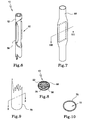
Figures 5A-5D shows steps in fabricating a steering mechanism, in accordance with yet a further embodiment of the invention, for a catheter; -
Figure 6 shows a schematic, three dimensional view of part of still a further embodiment of a steering mechanism for a catheter; -
Figure 7 shows a schematic, three dimensional view of the steering mechanism ofFigure 6 , after application of a protective sheath; -
Figure 8 shows a sectional end view of the steering mechanism ofFigure 7 taken along line VIII-VIII inFigure 7 ; -
Figure 9 shows a schematic, three dimensional view of part of an electrode sheath of a catheter for use with the steering mechanism ofFigures 6-8 ; -
Figure 10 shows a sectional, end view of the electrode sheath taken along line X-X; and -
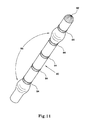
Figure 11 shows a schematic, three dimensional view of a distal part of an electrode sheath, in accordance with yet a further embodiment of the invention, for a catheter. - Referring firstly to
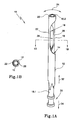
Figure 1 of the drawings, an embodiment of a steering mechanism for a catheter is designated generally by thereference numeral 10. Thesteering mechanism 10 includes a first, outertubular member 12 defining apassage 14. Anactuator 16 is received in thepassage 12. In this embodiment, theactuator 16 is also tubular. - The
tubular member 12 has a longitudinally extending bend-enhancing portion in the form of a longitudinally extendingcutaway portion 18 near adistal end 20 of thetubular member 12. Thecutaway portion 18 subtends an angle exceeding 180°. For example, assuming that thetubular member 12 has an outer diameter of approximately 0.66 mm, aweb 22 or a wall of thetubular member 12 remains having a width of about 0.25 mm and forms a "hinge" or "spine" about which thedistal end 20 of thetubular member 12 can bend in the direction ofarrows 24. - The
actuator 16 also has a longitudinally extending bend-enhancing,cutaway portion 26 coincident with thecutaway portion 18 of thetubular member 12. However, aweb 28 of thetubular actuator 16 lies opposed theweb 22 of thetubular member 12 as shown more clearly inFigure 1B of the drawings. - The
tubular member 12 and thetubular actuator 16 are of any suitable material of construction but, preferably, comprise superelastic alloys, such as nitinol. - A sheath (not shown in this embodiment) overlies the
tubular member 12 to contain theactuator 16 with respect to thetubular member 12 and also to inhibit the ingress of foreign material into thepassage 14 of thetubular member 12. Although the sheath may be slid on to the steering mechanism or everted and rolled on to the steering mechanism, one way to provide a covering is by the use of heat shrink materials or tubing such as a fluoro-ethylene polymer heat shrink tube which has appropriate strength, lubricity, and biocompatibility properties. - In use, the
steering mechanism 10 is inserted into a lumen of an elongate element in the form of an electrode sheath (not shown) of a catheter. A proximal end of thetubular member 12 is affixed to a handle (also not shown) allowing the catheter to be manipulated through the vascular system of a patient. A proximal end of thetubular member 12 is fixed in tension, compression, and rotation relative to the handle of the catheter. - Thus, a proximal end 16.1 of the
tubular member 12 includes anattachment formation 30 for attachment to a steering control arrangement such as the handle of the catheter. - In this regard, it is to be noted that a distal end 16.2 of the
actuator 16 is fixed to thedistal end 20 of thetubular member 12 to the extent necessary to move the various tubular members. - When the catheter is to be bent to the left, as viewed in
Figure 1A , thetubular actuator 16 is urged with respect totubular member 30, in the direction ofarrow 32. Conversely, to bend the catheter to the right, as viewed inFigure 1A , theactuator 16 is pulled in the direction ofarrow 34 by the control arrangement of the handle of the catheter. - In the embodiment of the
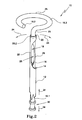
steering mechanism 10 shown inFigure 2 of the drawings, where, with reference toFigures 1A and 1B of the drawings, like reference numerals refer to like parts, theactuator 16 comprises a solid, wire member narrowed in the region of thecutaway portion 18 of thetubular member 12. The narrowed region is either offset with respect to the longitudinal axis of theactuator 16, as shown inFig 2 of the drawings, or, instead, the narrowed region is defined by apart 52 of reduced cross-section, as shown inFig 4 of the drawings. Thispart 52 is coincident with thecutaway portion 18 of thetubular member 12 to provide the bend-enhancing region of thesteering mechanism 10. - The
actuator 16 is secured to thedistal end 20 of thetubular member 12 at an attachment point or region 20.2. A part 16.3 of theactuator 16 protrudes distally of the attachment point 20.2. The part 16.3 of theactuator 16 is cranked as illustrated at 23 distally of the attachment point 20.2. Further, the portion 16.3 distally of thecrank 23 is shaped into the form of a predetermined shape, such as aloop 25, that lies in a plane that is generally transverse to a longitudinal axis of thetubular member 12. It will be appreciated that the predetermined shape could take other forms such as, for example, a helix, a spiral, or the like. In this embodiment, thewire actuator 16 is of any suitable material of construction such as, for example, stainless steels, superelastic alloys such as nitinol, or the like. The part 16.3 of the actuator is pre-formed into the desired shape. Thus, it will be appreciated that, by replacing thesteering mechanism 10 having one shape 16.3 ofactuator 16 with anactuator 16 having a differently shaped distal part 16.3, different shapes can be imparted to a distal end of the catheter as required by a clinician for particular applications. - As an enhancement of this embodiment, the part 16.3 of the
actuator 16 may carry, at longitudinally spaced intervals along the length of thepart 16. 3, radioopaque members 54. as shown inFigure 2A of the drawings. Thesemembers 54 are applied either as coatings or as short lengths of sleeves having the same length dimensions as electrodes (not shown) on the electrode sheath of the catheter. Further, when thesteering mechanism 10 is inserted into the electrode sheath, the radioopaque members 54 underlie the electrodes in register with the electrodes facilitating positioning of the electrodes by a clinician viewing the catheter via a fluoroscope. When themembers 54 are in the form of sleeves, they are made from tantalum tubing attached, for example, by crimping to the part 16.3 of theactuator 16. - Referring now to
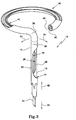
Figure 3 of the drawings, yet a further embodiment of a steering mechanism for a catheter is shown. Once again with reference to the previous drawings, like reference numerals refer to like parts, unless otherwise specified. - In this embodiment, the
steering mechanism 10 comprises theactuator 16 which is tubular and functions as a first actuator. Theactuator 16 terminates at atermination 36 proximally of thedistal end 20 of thetubular member 12. Thetubular actuator 16 controls bending of thetubular member 12 in the direction ofarrows 24 in the same way as described above with reference toFigure 1A of the drawings. This bending motion is facilitated by the cutaway, longitudinally extending bend-enhancingportions tubular member 12 and theactuator 16, respectively, being arranged proximally of thetermination 36. - The
tubular member 12 is shown to be cranked as illustrated at 38 distally of thetermination region 36 to extend further into aloop 42. A second, longitudinally extending,cutaway portion 40 is defined in thetubular member 12 between the crankedregion 38 and thedistal end 20 of thetubular member 12. Thetubular member 12 is pre-formed with thecrank 38 and theloop 42, for example, by heat-setting the material of thetubular member 12. - A further actuator in the form of a length of
wire 44 projects through the passages of thetubular member 12 and thetubular actuator 16. Adistal end 46 of thewire 44 is fast with thedistal end 20 of thetubular member 12, for example, by crimping the parts together. - The part of the
tubular member 12 distally of thetermination 36 is steered by manipulation of thetubular actuator 16. Thus, by pushing on theactuator 16, the distal part of thetubular member 12 is moved to the left, as viewed inFigure 3 of the drawings. Conversely, by pulling on thetubular actuator 16, the part of thetubular member 12 located distally of thetermination 36 is moved to the right. - The diameter of the
loop 42 is altered by manipulating thewire 44. Thus, if thewire 44 is pushed in the direction ofarrow 48, the diameter of theloop 42 is increased. Conversely, by pulling on thewire 44 in the direction ofarrow 50, the diameter of theloop 42 is reduced. It will also be appreciated that pushing and pulling thewire 44 in the direction of thearrows - It will be appreciated that the degree to which the distal part of the
tubular member 12 can be steered and the degree to which it can be bent is dependent on the shape and dimensions of thecutaway portions tubular member 12 and thetubular actuator 16, respectively. Similarly, the degree to which the radius or diameter of theloop 42 can be altered is governed by the shape and dimensions of thecutaway portion 40 of thetubular member 12 and by the dimensions and material properties of thewire 44. - In
Figure 3A of the drawings, a variation of the steering mechanism ofFigure 3 is shown. In this variation, the part of thetubular member 12 distally of thetermination 36 and, more particularly, theloop 42 carries a series of spaced radioopaque elements 54. Theseelements 54 are, once again, either applied as a coating to the outer surface of the tubular member by pad printing or, instead, the elements could be cuffs 55 of suitable radio opaque material such as tantalum. Thecuffs 55 are adhesively secured within thecutaway portion 40 and thecuffs 55 are dimensioned so as not to protrude beyond an imaginary circle having a centre coincident with a centre of thetubular member 12 and having the same outer diameter as that of thetubular member 12. Instead ofcuffs 55, the elements could also be ovoid to have a part abutting, and being adhesively secured to, a web orspine 57 of material remaining after thecutaway portion 40 of thetubular member 12 has been formed. Thecuffs 55, or ovoid elements, as the case may be, are adhesively secured to thetubular member 12 by a suitable adhesive such as a cyano-acrylate adhesive. - The sheath covering the
tubular member 12 may, in addition or instead, carry radio opaque elements at longitudinally spaced intervals pad printed on the sheath. - Referring now to
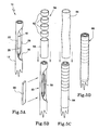
Figures 5A-5D of the drawings, yet a further embodiment of thesteering mechanism 10 is illustrated. Once again, with reference to the previous drawings, like reference numerals refer to like parts, unless otherwise specified. - In this embodiment, a centre of support in the form of an insert or
shim 56 is inserted between thewebs tubular member 12 and theactuator 16, respectively a shown inFigure 5B of the drawings. Theinsert 56 acts as a floating centre of support and is used to impart a more directional bending behaviour to thesteering mechanism 10. In this embodiment of the invention, a width of theinsert 56 does not exceed an outer diameter of thetubular member 12 and, therefore, is contained within the circumference of thetubular member 12. - To assist in retaining the
insert 56 in position relative to thetubular member 12 and theactuator 16, aprotective arrangement 58 is applied over thetubular member 12 to overlie and cover the bend-enhancingportion 60 of thetubular member 12 of thesteering mechanism 10. Theprotective arrangement 58 comprises, firstly, a series of containment rings 62 and a slightlylonger containment tube 64. The containment rings 62 and 64 are applied over thetubular member 12 in the region of the bend-enhancingportion 60. Typically, therings 62 have a length in the range of 0.5 mm to 1.5 mm and, preferably, about 1 mm. The shorter the length of therings 62, the greater the flexibility of thesteering mechanism 10. - The
tube 64 fits over the proximal end of the bend-enhancingportion 60 to reduce the likelihood of breaking at the proximal end of the bend-enhancingportion 60. It limits the amount of bend at the proximal end of the bend-enhancingportion 60 and provides a more gradual bending. The tube has a length of at least 10 mm with at least 5 mm overlying the proximal end of the bend-enhancingportion 60. Therings 62 and thetube 64 are of short segments of a suitable synthetic plastics material such as a thin-walled rigid polymer tubing, for example, a polyimide tubing. - Once the containment rings 62 and
tube 64 have been positioned on thetubular member 12, they are retained in position by a protective sheath in the form of asleeve 66 of heat shrink material to provide theprotective arrangement 58. - Referring now to
Figures 6 to 10 of the drawings, yet a further embodiment of the steering mechanism is illustrated. In particular, with reference toFigures 5A-5D of the drawings, like reference numerals refer to like parts, unless otherwise specified. - In this embodiment, and as shown more clearly in
Figure 6 of the drawings, themetal insert 56 has a width dimension exceeding that of an outer dimension of thetubular member 12. As a result, when the protective sheath, in the form of a length ofheat shrink tube 68 is applied over the bend-enhancingregion 60 of thesteering mechanism 10, a substantially ovoid cross-section is imparted to theprotective sheath 68 as shown more clearly inFigure 8 of the drawings. - Further, in this embodiment, an electrode sheath 70 (
Figure 9 ) of the catheter has a similar ovoid cross section, as shown inFigure 10 of the drawings. This ovoid cross section extends along theelectrode sheath 70 at least for the length of the bend-enhancingportion 60 of thetubular member 12 of thesteering mechanism 10. When thesteering mechanism 10 is inserted into alumen 72 of the electrode sheath, the ovoid cross section of theelectrode sheath 70 is coincident with the bend-enhancingportion 60 of the steering mechanism. - With this arrangement, relative rotation between the
steering mechanism 10 and theelectrode sheath 70 is inhibited while still permitting sliding movement, in a longitudinal direction, between thesteering mechanism 10 and theelectrode sheath 70. Thus, with this configuration ofelectrode sheath 70 andsteering mechanism 10, in-plane, bi-directional steering of the electrode sheath by thesteering mechanism 10 is facilitated. - In both of the preceding embodiments, either the
tubular member 12 may carry radio opaque elements in the form of pad printed coatings, tubes or cuffs, themetal insert 56 may carry longitudinally spaced radio opaque elements pad printed thereon and/or theprotective sheath 66 orprotective tube 68, as the case may be, may carry pad printed radio opaque elements at longitudinally spaced intervals thereon. - Referring to
Figure 11 , an embodiment of an electrode sheath for the catheter is illustrated and is designated generally by thereference numeral 80. - The
electrode sheath 80 carries adistal electrode 82 at its distal end andring electrodes 84 at longitudinally spaced intervals along a distal region of theelectrode sheath 80. - In this embodiment, prior to insertion of the
steering mechanism 10 into a lumen (not shown) of theelectrode sheath 80, theelectrode sheath 80 is modified to inhibit relative rotation between thesteering mechanism 10 and theelectrode sheath 80. More particularly, theelectrode sheath 80 is modified by being deformed in its distal region. - To achieve this deformation, a former, in the form of a length of wire (not shown), is inserted into the lumen of the
electrode sheath 80. For example, the former could be a 0.66 mm diameter NiTi wire. The wire inhibits excessive deformation of theelectrode sheath 80 and facilitates light crimping of theelectrode sheath 80. - Once the wire has been inserted into the lumen of the
electrode sheath 80, theelectrode sheath 80 is deformed by crimping between the first andsecond ring electrodes 84 and proximally of theproximal ring electrode 84 to form a pair of longitudinally spacedcrimped regions 86. - After completion of crimping to form the crimped
regions 86, the NiTi wire is removed and the steering mechanism is 10 is inserted into the lumen of theelectrode sheath 80. - The
crimped regions 86 result in a region of reduced cross section of the lumen of theelectrode sheath 80. The region of reduced cross section allows the passage of thesteering mechanism 10 past thecrimped regions 86 but causes sufficient frictional engagement between theelectrode sheath 80 and thesteering mechanism 10 to inhibit relative rotation between thesteering mechanism 10 and theelectrode sheath 80 on bending of thesteering mechanism 10. - Thus, when the
steering mechanism 10 steers the distal region of theelectrode sheath 80 in a first direction bending occurs in-plane. When thesteering mechanism 10 is manipulated to steer the distal end of theelectrode sheath 80 in an opposite direction, the frictional engagement between thesteering mechanism 10 and theelectrode sheath 80 facilitates in-plane changing of direction of the distal end of theelectrode sheath 80. This allows greater control of the distal end of theelectrode sheath 80 by a clinician. - It is an advantage of the invention that an accurately steerable catheter can be obtained using the
steering mechanism 10. Thesteering mechanism 10 is simple to produce. This simplicity results in a comparatively lower cost steering mechanism. Still further, thesteering mechanism 10 may be tailored to achieve varying degrees of flexibility by appropriate shaping of thecutaway portions - It is yet a further advantage of the invention that a
steering mechanism 10 is easily formed into a loop. Such a loop allows ablation to be effected at an ostium of a pulmonary vein using a catheter incorporating thesteering mechanism 10. In other words, by adjusting the configuration of each of thecutaway portions steering mechanisms 10 can be provided with differing distal shapes. A clinician can select the steering mechanism of the required shape to impart that shape to the electrode sheath to enable the clinician to perform a desired function. This further improves the versatility of a modular catheter system including the steering mechanism. - It will be appreciated by persons skilled in the art that numerous variations and modifications may be made to the devices as shown in the specific embodiments without departing from the spirit or scope of the broad description. The disclosure, therefore, is to be considered in all respects as illustrative and not restrictive.
Claims (15)
- A steering mechanism (10) for a catheter, the steering mechanism including:a tubular member (12) defining a passage (14),; andan actuator (16) received in the passage (14) of the tubular member (12), a distal part of the actuator (16) being fast with a distal part of the tubular member (12) characterised in that the tubular member (12) defines a longitudinally extending, continuous cutaway portion (18) to define a bend enhancing region at a predetermined position along the tubular member (12) and in that the actuator (16) is one of a solid element and a tubular element positioned co-axially in the passage (14) of the tubular member (12), the actuator (16) having a longitudinally extending, continuous region of reduced cross-section (26, 52) shaped to define a bend enhancing region which is coincident with the cutaway portion (18) of the tubular member (12).
- The mechanism (10) of claim 1 in which the cutaway portion (18) of the tubular member (12)subtends an angle greater than 180° of a wall of the tubular member (12) to retain a longitudinally extending web or spine (22) of material of the tubular member (12).
- The mechanism (10) of claim 1 or claim 2 in which the actuator (16) is a tubular element and the region of reduced cross-section is a cutaway portion (26) defining the bend-enhancing region of the actuator (16), the cutaway portion (26) subtending an angle greater than 180° of a wall of the tubular element (16) to retain a longitudinally extending web or spine (28) of material of the tubular element, the spines (22, 28) of the tubular member (12) and the tubular element (16) lying in opposed relationship relative to each other.
- The mechanism (10) of claim 3 in which an insert (56) is arranged between the spines (22, 28) of the tubular member (12) and the tubular element (16) for controlling bending of the tubular member (12) and the tubular element (16).
- The mechanism (10) of any one of the preceding claims which includes a protective arrangement (58) received over the tubular member (12) to inhibit the ingress of foreign material into the tubular member (12).
- The mechanism (10) of claim 5 in which the protective arrangement (66) comprises a reinforcing structure (62, 64) overlying the cutaway portion of the tubular member (12) and over which the protective sheath (66) is received.
- The mechanism (10) of claim 1 in which the actuator (16) is a solid element having the region of reduced cross-section (52) coincident with the cutaway portion (18) of the tubular member (12).
- The mechanism (10) of any one of the preceding claims in which the tubular member (12) and the actuator (16) are of a superelastic material.
- A catheter which includes:an elongate element (70, 80) defining a lumen (72); anda steering mechanism (10), as claimed in any one of the preceding claims, received within the lumen (72).
- The catheter of claim 9 in which the elongate element (70, 80) is secured against rotation relative to the steering mechanism (10) on bending.
- The catheter of claim 10 in which the elongate element (80) is secured against rotation relative to the steering mechanism (10) by being deformed at at least one region of the elongate element in register with the cutaway portion (18) of the tubular member (12).
- The catheter of claim 10 in which the elongate element (70, 80) has a non-circular cross-section, when viewed end-on, at least in that region of the elongate element (70, 80) coincident with the cutaway portion (18) of the tubular member (12) of the steering mechanism (10) to inhibit relative rotation between the elongate element (70, 80) and the steering mechanism (10) on bending of the elongate element (70, 80) by the steering mechanism (10).
- A method of fabricating a catheter as claimed in any one of claims 9 to 11, the method including:providing the elongate element (80); anddeforming at least one region (86) of the elongate element (80) in register with the cutaway portion (18) of the steering mechanism (10) to inhibit relative rotation of the elongate element (80) and the steering mechanism (10) on bending.
- The method of claim 13 which includes deforming the elongate element (80) by crimping the elongate element (80).
- The method of claim 14 which includes inserting a former into the lumen (72) of the elongate element (80) prior to crimping to limit deformation of the elongate element (80) on being crimped.
Applications Claiming Priority (2)
| Application Number | Priority Date | Filing Date | Title |
|---|---|---|---|
| US59972004P | 2004-08-05 | 2004-08-05 | |
| EP05706254.9A EP1781363B1 (en) | 2004-08-05 | 2005-02-18 | A steerable catheter |
Related Parent Applications (2)
| Application Number | Title | Priority Date | Filing Date |
|---|---|---|---|
| EP05706254.9A Division-Into EP1781363B1 (en) | 2004-08-05 | 2005-02-18 | A steerable catheter |
| EP05706254.9 Division | 2005-02-18 |
Publications (1)
| Publication Number | Publication Date |
|---|---|
| EP2198912A1 true EP2198912A1 (en) | 2010-06-23 |
Family
ID=35786801
Family Applications (2)
| Application Number | Title | Priority Date | Filing Date |
|---|---|---|---|
| EP10159520A Withdrawn EP2198912A1 (en) | 2004-08-05 | 2005-02-18 | A steerable catheter |
| EP05706254.9A Active EP1781363B1 (en) | 2004-08-05 | 2005-02-18 | A steerable catheter |
Family Applications After (1)
| Application Number | Title | Priority Date | Filing Date |
|---|---|---|---|
| EP05706254.9A Active EP1781363B1 (en) | 2004-08-05 | 2005-02-18 | A steerable catheter |
Country Status (7)
| Country | Link |
|---|---|
| US (1) | US8641697B2 (en) |
| EP (2) | EP2198912A1 (en) |
| JP (1) | JP5405742B2 (en) |
| CN (1) | CN101001660A (en) |
| AU (1) | AU2005269245B2 (en) |
| CA (1) | CA2575871A1 (en) |
| WO (1) | WO2006012668A1 (en) |
Families Citing this family (42)
| Publication number | Priority date | Publication date | Assignee | Title |
|---|---|---|---|---|
| US8409191B2 (en) | 2004-11-04 | 2013-04-02 | Boston Scientific Scimed, Inc. | Preshaped ablation catheter for ablating pulmonary vein ostia within the heart |
| WO2006092014A1 (en) | 2005-03-04 | 2006-09-08 | Cathrx Ltd | A catheter handle and a catheter assembly including such a handle |
| US8535303B2 (en) | 2005-05-05 | 2013-09-17 | Boston Scientific Scimed, Inc. | Preshaped localization catheter, system, and method for graphically reconstructing pulmonary vein ostia |
| AU2006326909B2 (en) | 2005-12-23 | 2012-08-16 | Cathrx Ltd | Irrigation catheter |
| US9642982B2 (en) | 2006-05-05 | 2017-05-09 | Cathrx Ltd. | Modular catheter assembly |
| WO2007128064A1 (en) | 2006-05-08 | 2007-11-15 | Cathrx Ltd | Shape imparting mechanism insertion |
| US9008795B2 (en) | 2006-08-04 | 2015-04-14 | Cathrx Ltd | Catheter handle assembly |
| AU2007231733B2 (en) | 2006-11-28 | 2014-03-13 | Cathrx Ltd | A catheter steering system |
| AU2008202483B2 (en) | 2007-06-15 | 2011-07-14 | Cathrx Ltd | A deflectable stylet |
| AU2009225951B2 (en) * | 2008-03-20 | 2011-09-15 | Cathrx Ltd | A steerable stylet |
| CN103961050B (en) * | 2008-04-18 | 2016-09-28 | 福蒂美迪克斯外科医疗器材有限公司 | A kind of instrument for endoscopic applications |
| US8740884B2 (en) * | 2008-04-18 | 2014-06-03 | Fortimedix B.V. | Instrument for endoscopic applications or the like |
| US20100121278A1 (en) | 2008-11-13 | 2010-05-13 | David Fowler | Super elastic loop extraluminal materials delivery instrument |
| US11406791B2 (en) | 2009-04-03 | 2022-08-09 | Scientia Vascular, Inc. | Micro-fabricated guidewire devices having varying diameters |
| EP2370237B1 (en) | 2008-12-08 | 2015-12-02 | Jeff Christian | Micro-cutting machine for forming cuts in products |
| US10363389B2 (en) | 2009-04-03 | 2019-07-30 | Scientia Vascular, Llc | Micro-fabricated guidewire devices having varying diameters |
| ES2538816T3 (en) | 2009-01-28 | 2015-06-24 | Apriomed Ab | Adjustable cutting medical instruments |
| US9526863B2 (en) * | 2009-02-08 | 2016-12-27 | Neuronal Protection System, Llc | Devices and methods for perfusion therapy |
| US8920369B2 (en) | 2009-06-24 | 2014-12-30 | Shifamed Holdings, Llc | Steerable delivery sheaths |
| AU2015210338B2 (en) * | 2009-06-24 | 2018-02-01 | Shifamed Holdings, Llc | Steerable medical delivery devices and methods of use |
| US8323241B2 (en) * | 2009-06-24 | 2012-12-04 | Shifamed Holdings, Llc | Steerable medical delivery devices and methods of use |
| EP2402050A1 (en) * | 2009-10-14 | 2012-01-04 | Olympus Medical Systems Corp. | Flexible medical tube and insertion part of medical instrument |
| AU2010324518B2 (en) | 2009-11-30 | 2015-12-24 | Cathrx Ltd | Catheter handle |
| US8369923B2 (en) * | 2010-04-14 | 2013-02-05 | St. Jude Medical, Atrial Fibrillation Division, Inc. | Dual-deflecting electrophysiology catheter |
| JP5232284B2 (en) * | 2011-10-21 | 2013-07-10 | 日本ライフライン株式会社 | Electrode catheter |
| US8961550B2 (en) | 2012-04-17 | 2015-02-24 | Indian Wells Medical, Inc. | Steerable endoluminal punch |
| US8684953B2 (en) | 2012-05-13 | 2014-04-01 | Ozca Engineering Solutions Ltd. | Steering tool |
| US9138566B2 (en) * | 2012-05-13 | 2015-09-22 | Bendit Technologies Ltd. | Steering tool |
| WO2014013564A1 (en) * | 2012-07-18 | 2014-01-23 | テルモ株式会社 | Medical treatment instrument |
| US10849684B2 (en) | 2013-06-07 | 2020-12-01 | Cathrx Ltd | Electrical lead for a catheter and method of manufacturing |
| JP6797131B2 (en) | 2015-03-27 | 2020-12-09 | カリラ メディカル インコーポレイテッド | Manipulable medical devices, systems and usage |
| CN107708785B (en) | 2015-04-24 | 2021-08-20 | 卡里拉医疗股份有限公司 | Steerable medical devices, systems, and methods of use |
| WO2017083257A1 (en) | 2015-11-09 | 2017-05-18 | Shifamed Holdings, Llc | Steering assemblies for medical devices, and methods of use |
| JP6718265B2 (en) * | 2016-03-22 | 2020-07-08 | テルモ株式会社 | Medical tube manufacturing method |
| US11052228B2 (en) | 2016-07-18 | 2021-07-06 | Scientia Vascular, Llc | Guidewire devices having shapeable tips and bypass cuts |
| US11207502B2 (en) | 2016-07-18 | 2021-12-28 | Scientia Vascular, Llc | Guidewire devices having shapeable tips and bypass cuts |
| US10821268B2 (en) | 2016-09-14 | 2020-11-03 | Scientia Vascular, Llc | Integrated coil vascular devices |
| US11141566B2 (en) * | 2016-11-06 | 2021-10-12 | Bendit Technologies Ltd. | Steering tool |
| US10653862B2 (en) * | 2016-11-07 | 2020-05-19 | Edwards Lifesciences Corporation | Apparatus for the introduction and manipulation of multiple telescoping catheters |
| US11452541B2 (en) | 2016-12-22 | 2022-09-27 | Scientia Vascular, Inc. | Intravascular device having a selectively deflectable tip |
| ES2966345T3 (en) | 2017-05-26 | 2024-04-22 | Scientia Vascular Inc | Microfabricated medical device with a non-helical cutting arrangement |
| US11305095B2 (en) | 2018-02-22 | 2022-04-19 | Scientia Vascular, Llc | Microfabricated catheter having an intermediate preferred bending section |
Citations (5)
| Publication number | Priority date | Publication date | Assignee | Title |
|---|---|---|---|---|
| US5306245A (en) | 1993-02-23 | 1994-04-26 | Advanced Surgical Inc. | Articulating device |
| US5329923A (en) | 1991-02-15 | 1994-07-19 | Lundquist Ingemar H | Torquable catheter |
| US5976075A (en) | 1997-12-15 | 1999-11-02 | University Of Massachusetts | Endoscope deployment apparatus |
| US6048339A (en) | 1998-06-29 | 2000-04-11 | Endius Incorporated | Flexible surgical instruments with suction |
| US20040116849A1 (en) | 2002-12-16 | 2004-06-17 | Gardeski Kenneth C. | Steerable medical device having means for imparting curves the device and in elongated implantable medical instruments |
Family Cites Families (20)
| Publication number | Priority date | Publication date | Assignee | Title |
|---|---|---|---|---|
| US4101984A (en) | 1975-05-09 | 1978-07-25 | Macgregor David C | Cardiovascular prosthetic devices and implants with porous systems |
| DE3507119A1 (en) * | 1985-02-28 | 1986-08-28 | Siemens AG, 1000 Berlin und 8000 München | ADJUSTABLE ENDOCARDIAL ELECTRODE ARRANGEMENT |
| US4972846A (en) | 1989-01-31 | 1990-11-27 | W. L. Gore & Associates, Inc. | Patch electrodes for use with defibrillators |
| US5282845A (en) | 1990-10-01 | 1994-02-01 | Ventritex, Inc. | Multiple electrode deployable lead |
| US5454787A (en) | 1991-02-15 | 1995-10-03 | Lundquist; Ingemar H. | Torquable tubular assembly and torquable catheter utilizing the same |
| AU660444B2 (en) | 1991-02-15 | 1995-06-29 | Ingemar H. Lundquist | Torquable catheter and method |
| DE4201280C1 (en) | 1992-01-18 | 1992-12-10 | Richard Wolf Gmbh, 7134 Knittlingen, De | |
| US5269810A (en) | 1992-06-19 | 1993-12-14 | W. L. Gore & Associates, Inc. | Patch electrode |
| US5441483A (en) * | 1992-11-16 | 1995-08-15 | Avitall; Boaz | Catheter deflection control |
| US5522874A (en) | 1994-07-28 | 1996-06-04 | Gates; James T. | Medical lead having segmented electrode |
| JP3835703B2 (en) | 1995-05-01 | 2006-10-18 | ボストン サイエンティフィック リミテッド | System for sensing subsurface temperature of body tissue during ablation with actively cooled electrodes |
| US5755758A (en) | 1995-11-07 | 1998-05-26 | Medtronic, Inc. | Intramuscular stimulation lead with enhanced infection resistance |
| US6071278A (en) | 1996-02-28 | 2000-06-06 | Ep Technologies, Inc. | Tissue heating and ablation systems and methods using porous electrode structures with specified electrical resistivities |
| US6332880B1 (en) * | 1996-12-19 | 2001-12-25 | Ep Technologies, Inc. | Loop structures for supporting multiple electrode elements |
| US6076012A (en) * | 1996-12-19 | 2000-06-13 | Ep Technologies, Inc. | Structures for supporting porous electrode elements |
| US5931862A (en) | 1997-12-22 | 1999-08-03 | Pacesetter, Inc. | Medical lead and method of making and using with sodium sulfosuccinic ester |
| CN100521868C (en) | 1999-10-26 | 2009-07-29 | 伊比登株式会社 | Multilayer printed wiring board and method of producing multilayer printed wiring board |
| IL140780A0 (en) | 2001-01-08 | 2002-02-10 | Gaber Benny | Deflectable guiding apparatus |
| US6837867B2 (en) * | 2001-04-30 | 2005-01-04 | Biosense Webster, Inc. | Steerable catheter with reinforced tip |
| US6984232B2 (en) * | 2003-01-17 | 2006-01-10 | St. Jude Medical, Daig Division, Inc. | Ablation catheter assembly having a virtual electrode comprising portholes |
-
2005
- 2005-02-18 WO PCT/AU2005/000216 patent/WO2006012668A1/en active Application Filing
- 2005-02-18 EP EP10159520A patent/EP2198912A1/en not_active Withdrawn
- 2005-02-18 US US11/659,274 patent/US8641697B2/en active Active
- 2005-02-18 JP JP2007524127A patent/JP5405742B2/en not_active Expired - Fee Related
- 2005-02-18 CA CA002575871A patent/CA2575871A1/en not_active Abandoned
- 2005-02-18 AU AU2005269245A patent/AU2005269245B2/en not_active Ceased
- 2005-02-18 CN CNA2005800264827A patent/CN101001660A/en active Pending
- 2005-02-18 EP EP05706254.9A patent/EP1781363B1/en active Active
Patent Citations (5)
| Publication number | Priority date | Publication date | Assignee | Title |
|---|---|---|---|---|
| US5329923A (en) | 1991-02-15 | 1994-07-19 | Lundquist Ingemar H | Torquable catheter |
| US5306245A (en) | 1993-02-23 | 1994-04-26 | Advanced Surgical Inc. | Articulating device |
| US5976075A (en) | 1997-12-15 | 1999-11-02 | University Of Massachusetts | Endoscope deployment apparatus |
| US6048339A (en) | 1998-06-29 | 2000-04-11 | Endius Incorporated | Flexible surgical instruments with suction |
| US20040116849A1 (en) | 2002-12-16 | 2004-06-17 | Gardeski Kenneth C. | Steerable medical device having means for imparting curves the device and in elongated implantable medical instruments |
Also Published As
| Publication number | Publication date |
|---|---|
| EP1781363A1 (en) | 2007-05-09 |
| EP1781363B1 (en) | 2019-06-05 |
| EP1781363A4 (en) | 2008-10-01 |
| JP5405742B2 (en) | 2014-02-05 |
| JP2008508063A (en) | 2008-03-21 |
| US8641697B2 (en) | 2014-02-04 |
| CA2575871A1 (en) | 2006-02-09 |
| AU2005269245A1 (en) | 2006-02-09 |
| AU2005269245B2 (en) | 2011-09-15 |
| CN101001660A (en) | 2007-07-18 |
| WO2006012668A1 (en) | 2006-02-09 |
| US20090131865A1 (en) | 2009-05-21 |
Similar Documents
| Publication | Publication Date | Title |
|---|---|---|
| EP1781363B1 (en) | A steerable catheter | |
| US5944689A (en) | Variable curve electrophysiology catheter | |
| EP1927375B1 (en) | A catheter steering system | |
| AU665358B2 (en) | Steerable stylet and manipulative handle assembly | |
| EP1323448B1 (en) | Dual-function catheter handle | |
| US5397321A (en) | Variable curve electrophysiology catheter | |
| US5391147A (en) | Steerable catheter with adjustable bend location and/or radius and method | |
| US5656029A (en) | Steerable catheter with adjustable bend location and/or radius and method | |
| US6663588B2 (en) | Active counterforce handle for use in bidirectional deflectable tip instruments | |
| EP1005839B1 (en) | Bidirectional electrode cathether | |
| US5833604A (en) | Variable stiffness electrophysiology catheter | |
| US20040059257A1 (en) | Deflectable guiding apparatus | |
| WO1997001302A1 (en) | Endoscope with protruding member and method | |
| JP4751553B2 (en) | Guiding aid | |
| WO1995003742A1 (en) | Bendable tip assemblies for catheters | |
| JP2022520849A (en) | Guide extension catheter | |
| AU2949195A (en) | Endoscope with protruding member and method |
Legal Events
| Date | Code | Title | Description |
|---|---|---|---|
| PUAI | Public reference made under article 153(3) epc to a published international application that has entered the european phase |
Free format text: ORIGINAL CODE: 0009012 |
|
| 17P | Request for examination filed |
Effective date: 20100409 |
|
| AC | Divisional application: reference to earlier application |
Ref document number: 1781363 Country of ref document: EP Kind code of ref document: P |
|
| AK | Designated contracting states |
Kind code of ref document: A1 Designated state(s): AT BE BG CH CY CZ DE DK EE ES FI FR GB GR HU IE IS IT LI LT LU MC NL PL PT RO SE SI SK TR |
|
| 17Q | First examination report despatched |
Effective date: 20120822 |
|
| STAA | Information on the status of an ep patent application or granted ep patent |
Free format text: STATUS: EXAMINATION IS IN PROGRESS |
|
| STAA | Information on the status of an ep patent application or granted ep patent |
Free format text: STATUS: THE APPLICATION IS DEEMED TO BE WITHDRAWN |
|
| 18D | Application deemed to be withdrawn |
Effective date: 20200603 |