EP2193746A1 - Device to obtain a blood sample - Google Patents
Device to obtain a blood sample Download PDFInfo
- Publication number
- EP2193746A1 EP2193746A1 EP08170441A EP08170441A EP2193746A1 EP 2193746 A1 EP2193746 A1 EP 2193746A1 EP 08170441 A EP08170441 A EP 08170441A EP 08170441 A EP08170441 A EP 08170441A EP 2193746 A1 EP2193746 A1 EP 2193746A1
- Authority
- EP
- European Patent Office
- Prior art keywords
- lancet
- flywheel
- movement
- drive
- drive rod
- Prior art date
- Legal status (The legal status is an assumption and is not a legal conclusion. Google has not performed a legal analysis and makes no representation as to the accuracy of the status listed.)
- Granted
Links
Images


Classifications
-
- A—HUMAN NECESSITIES
- A61—MEDICAL OR VETERINARY SCIENCE; HYGIENE
- A61B—DIAGNOSIS; SURGERY; IDENTIFICATION
- A61B5/00—Measuring for diagnostic purposes; Identification of persons
- A61B5/15—Devices for taking samples of blood
- A61B5/151—Devices specially adapted for taking samples of capillary blood, e.g. by lancets, needles or blades
- A61B5/15186—Devices loaded with a single lancet, i.e. a single lancet with or without a casing is loaded into a reusable drive device and then discarded after use; drive devices reloadable for multiple use
- A61B5/15188—Constructional features of reusable driving devices
- A61B5/15192—Constructional features of reusable driving devices comprising driving means, e.g. a spring, for retracting the lancet unit into the driving device housing
- A61B5/15194—Constructional features of reusable driving devices comprising driving means, e.g. a spring, for retracting the lancet unit into the driving device housing fully automatically retracted, i.e. the retraction does not require a deliberate action by the user, e.g. by terminating the contact with the patient's skin
-
- A—HUMAN NECESSITIES
- A61—MEDICAL OR VETERINARY SCIENCE; HYGIENE
- A61B—DIAGNOSIS; SURGERY; IDENTIFICATION
- A61B5/00—Measuring for diagnostic purposes; Identification of persons
- A61B5/15—Devices for taking samples of blood
- A61B5/150007—Details
- A61B5/150015—Source of blood
- A61B5/150022—Source of blood for capillary blood or interstitial fluid
-
- A—HUMAN NECESSITIES
- A61—MEDICAL OR VETERINARY SCIENCE; HYGIENE
- A61B—DIAGNOSIS; SURGERY; IDENTIFICATION
- A61B5/00—Measuring for diagnostic purposes; Identification of persons
- A61B5/15—Devices for taking samples of blood
- A61B5/150007—Details
- A61B5/150053—Details for enhanced collection of blood or interstitial fluid at the sample site, e.g. by applying compression, heat, vibration, ultrasound, suction or vacuum to tissue; for reduction of pain or discomfort; Skin piercing elements, e.g. blades, needles, lancets or canulas, with adjustable piercing speed
- A61B5/150167—Adjustable piercing speed of skin piercing element, e.g. blade, needle, lancet or canula, for example with varying spring force or pneumatic drive
-
- A—HUMAN NECESSITIES
- A61—MEDICAL OR VETERINARY SCIENCE; HYGIENE
- A61B—DIAGNOSIS; SURGERY; IDENTIFICATION
- A61B5/00—Measuring for diagnostic purposes; Identification of persons
- A61B5/15—Devices for taking samples of blood
- A61B5/150007—Details
- A61B5/150175—Adjustment of penetration depth
- A61B5/15019—Depth adjustment mechanism using movable stops located inside the piercing device housing and limiting the travel of the drive mechanism
-
- A—HUMAN NECESSITIES
- A61—MEDICAL OR VETERINARY SCIENCE; HYGIENE
- A61B—DIAGNOSIS; SURGERY; IDENTIFICATION
- A61B5/00—Measuring for diagnostic purposes; Identification of persons
- A61B5/15—Devices for taking samples of blood
- A61B5/150007—Details
- A61B5/150374—Details of piercing elements or protective means for preventing accidental injuries by such piercing elements
- A61B5/150381—Design of piercing elements
- A61B5/150412—Pointed piercing elements, e.g. needles, lancets for piercing the skin
- A61B5/150419—Pointed piercing elements, e.g. needles, lancets for piercing the skin comprising means for capillary action
-
- A—HUMAN NECESSITIES
- A61—MEDICAL OR VETERINARY SCIENCE; HYGIENE
- A61B—DIAGNOSIS; SURGERY; IDENTIFICATION
- A61B5/00—Measuring for diagnostic purposes; Identification of persons
- A61B5/15—Devices for taking samples of blood
- A61B5/150007—Details
- A61B5/150374—Details of piercing elements or protective means for preventing accidental injuries by such piercing elements
- A61B5/150381—Design of piercing elements
- A61B5/150503—Single-ended needles
- A61B5/150511—Details of construction of shaft
-
- A—HUMAN NECESSITIES
- A61—MEDICAL OR VETERINARY SCIENCE; HYGIENE
- A61B—DIAGNOSIS; SURGERY; IDENTIFICATION
- A61B5/00—Measuring for diagnostic purposes; Identification of persons
- A61B5/15—Devices for taking samples of blood
- A61B5/151—Devices specially adapted for taking samples of capillary blood, e.g. by lancets, needles or blades
- A61B5/15101—Details
- A61B5/15103—Piercing procedure
- A61B5/15107—Piercing being assisted by a triggering mechanism
- A61B5/15113—Manually triggered, i.e. the triggering requires a deliberate action by the user such as pressing a drive button
-
- A—HUMAN NECESSITIES
- A61—MEDICAL OR VETERINARY SCIENCE; HYGIENE
- A61B—DIAGNOSIS; SURGERY; IDENTIFICATION
- A61B5/00—Measuring for diagnostic purposes; Identification of persons
- A61B5/15—Devices for taking samples of blood
- A61B5/151—Devices specially adapted for taking samples of capillary blood, e.g. by lancets, needles or blades
- A61B5/15101—Details
- A61B5/15115—Driving means for propelling the piercing element to pierce the skin, e.g. comprising mechanisms based on shape memory alloys, magnetism, solenoids, piezoelectric effect, biased elements, resilient elements, vacuum or compressed fluids
- A61B5/15117—Driving means for propelling the piercing element to pierce the skin, e.g. comprising mechanisms based on shape memory alloys, magnetism, solenoids, piezoelectric effect, biased elements, resilient elements, vacuum or compressed fluids comprising biased elements, resilient elements or a spring, e.g. a helical spring, leaf spring, or elastic strap
-
- A—HUMAN NECESSITIES
- A61—MEDICAL OR VETERINARY SCIENCE; HYGIENE
- A61B—DIAGNOSIS; SURGERY; IDENTIFICATION
- A61B5/00—Measuring for diagnostic purposes; Identification of persons
- A61B5/15—Devices for taking samples of blood
- A61B5/151—Devices specially adapted for taking samples of capillary blood, e.g. by lancets, needles or blades
- A61B5/15101—Details
- A61B5/15126—Means for controlling the lancing movement, e.g. 2D- or 3D-shaped elements, tooth-shaped elements or sliding guides
- A61B5/15128—Means for controlling the lancing movement, e.g. 2D- or 3D-shaped elements, tooth-shaped elements or sliding guides comprising 2D- or 3D-shaped elements, e.g. cams, curved guide rails or threads
-
- A—HUMAN NECESSITIES
- A61—MEDICAL OR VETERINARY SCIENCE; HYGIENE
- A61B—DIAGNOSIS; SURGERY; IDENTIFICATION
- A61B5/00—Measuring for diagnostic purposes; Identification of persons
- A61B5/15—Devices for taking samples of blood
- A61B5/151—Devices specially adapted for taking samples of capillary blood, e.g. by lancets, needles or blades
- A61B5/15146—Devices loaded with multiple lancets simultaneously, e.g. for serial firing without reloading, for example by use of stocking means.
-
- A—HUMAN NECESSITIES
- A61—MEDICAL OR VETERINARY SCIENCE; HYGIENE
- A61B—DIAGNOSIS; SURGERY; IDENTIFICATION
- A61B5/00—Measuring for diagnostic purposes; Identification of persons
- A61B5/15—Devices for taking samples of blood
- A61B5/151—Devices specially adapted for taking samples of capillary blood, e.g. by lancets, needles or blades
- A61B5/15186—Devices loaded with a single lancet, i.e. a single lancet with or without a casing is loaded into a reusable drive device and then discarded after use; drive devices reloadable for multiple use
- A61B5/15188—Constructional features of reusable driving devices
- A61B5/1519—Constructional features of reusable driving devices comprising driving means, e.g. a spring, for propelling the piercing unit
-
- A—HUMAN NECESSITIES
- A61—MEDICAL OR VETERINARY SCIENCE; HYGIENE
- A61B—DIAGNOSIS; SURGERY; IDENTIFICATION
- A61B5/00—Measuring for diagnostic purposes; Identification of persons
- A61B5/15—Devices for taking samples of blood
- A61B5/155—Devices specially adapted for continuous or multiple sampling, e.g. at predetermined intervals
Definitions
- the invention relates to a device for obtaining a blood sample, which has a lancet, a lancing drive with drive spring and a control device for controlling the rapid puncture and withdrawal movement of the lancet.
- Such a device is used primarily for diabetics for regular self-monitoring of blood sugar levels.
- the lancet is driven with its tip into the skin of a body part, preferably in the fingertip. From the small wound then a small amount of blood comes out, which is taken either directly or through a capillary in the lancet. Subsequently, this blood sample can be analyzed.
- WO 2007/073870 describes a microsampler lancing system whose lancing drive comprises a coil spring which drives a push rod forward.
- the head of the push rod can be connected to the lancet.
- the movement of the lancet in the axial direction follows a predetermined movement profile and includes a propulsion phase, in which the lancet is inserted to a predetermined maximum penetration depth, and an immediately following withdrawal phase, in which the lancet is partially retracted to a predetermined residual stitch depth.
- the residual stitch depth is of great importance for optimal sample collection and lowest possible pain.
- the propulsion phase the push rod contacts a stop.
- the drive spring is overstretched, so that the push rod with the coupled lancet during the subsequent retraction phase of the drive spring is also withdrawn.
- the puncturing drive comprises a torsion spring, a tensioning rotor and a driven rotor driven by the tensioned spring.
- a control device for converting the rotational movement of the drive rotor in a linear insertion / and return movement of a lancing element is a control device in the form of a cam control.
- a lancet control cam is formed as a groove in the drive rotor and is driven off by a cam rider, which is connected to the lancet holder.
- US Pat. No. 6,206,901 B1 describes a blood sampling device with a lancet, which is driven by a plunger and a drive spring.
- the lancet is decoupled from the drive spring on a part of its propulsion phase.
- a second spring is provided to return the lancet after the puncture from the wound.
- This return spring is tensioned only during the propulsion phase, by storing kinetic energy of the lancet in the spring and returned to the lancet after reaching the maximum tension of the return spring.
- the disadvantage is that the lancet is braked prematurely by the return spring. As a result, the entry of the lancet into the skin of the patient is slower and more painful.
- EP 0 036 443 B1 describes a lancing device in which the lancet is decoupled from the drive spring during part of the lancing movement. The return of the lancet after the puncture by a second spring, which is stretched by the lancet during its propulsion movement.
- Puncture drives with a drive spring whose spring force is transmitted linearly in the puncture direction directly to the lancet are structurally simple and therefore just as reliable as cost-effective and also space-saving. They allow in particular the installation in a narrow handset that is comfortable and easy to handle by the user. To ensure a quick and painless puncture, rather strong springs are used. There is a risk that the needle pierces several times by reverberating. In the blood collection system according to EP 1 852 069 A1 Therefore, a vibration control device is provided which acts on the oscillatory system of lancet and drive spring so that a multiple grooving is prevented.
- a displaceable stop can limit the oscillating movement of the lancet in the direction of puncture.
- a damping device for example in the form of a hydraulic or pneumatic damper, can be provided.
- a displacement of the drive spring may be provided, by which the zero point of the oscillation of the drive spring is displaced so that a repeated piercing of the lancet is excluded even at maximum deflection of the drive spring. The vibration itself is not affected.
- Punches whose control device works with a cam are basically well suited for alternately fast and slow motion phases, but have the disadvantage of large strokes that they are relatively large, otherwise increase the pitch angle of the cam to self-locking.
- This can be counteracted by mounting a fast short-stroke lancing drive, which drives the lancet, on a sliding carriage that performs the large slow movements for engaging and disengaging the lancet.
- This sliding carriage can also be used at the same time to tension the lancing drive, for example, by the ram, which is to drive the lancet forward, is driven against a stationary mounted in the housing stop until the drive spring is tensioned and locked in the release mechanism.
- the present invention is therefore based on the technical problem of providing a structurally simple lancing drive, which works with a single, acting in the direction of the axis of movement of the lancet drive spring and still allows a vibration-free puncture.
- the lancing drive should also be suitable, in the context of a sliding mechanism, for the slow complete retraction of the lancet, used for docking and releasing magazinated disposable lancets and / or for tensioning the drive spring, to be used.
- the object is achieved according to the characterizing part of the first claim by a movably mounted flywheel and a coupling member which couples the flywheel to the drive rod or the lancet.
- the flywheel By driving the lancet, the flywheel is set in motion. Part of the kinetic energy of the drive rod and the lancet is used to accelerate the flywheel. Once the lancet reaches the reversal point that defines the maximum puncture depth, the momentum stored in the flywheel causes the lancet to retract. The absorbed kinetic energy is transferred back to the drive rod and the attached lancet.
- the coupled flywheel allows a smooth transition from the forward to the return movement of the lancet realize and thus a particularly vibration-free pain-free puncture.
- a coupling mechanism which comprises at least one, along a linear movement path movable flywheel and a coupling rod, one end of which is connected to the drive rod and the other end is movably mounted on the flywheel.
- the coupling transmission transmits the forward movement of the drive rod with the coupled lancet on the flywheel body, which is thereby set in a translational movement.
- the coupling gear does not cause the propulsion of the lancet, but runs passively with.
- the power of the relaxing spring is not only used to drive the lancet, but also to accelerate the flywheel. If the lancet passes through the reversal point, which corresponds to the maximum penetration depth, the inertial mass of the flywheel body ensures that it continues to move.
- This continued translational movement is transmitted through the coupling rod to the drive rod and thereby initiates the withdrawal movement of the lancet.
- the kinetic energy stored in the flywheel body is transformed into kinetic energy the drive rod and the lancet implemented.
- the coupling gear also controls and limits the penetration depth very precisely.
- the trajectory of the flywheel body is substantially transverse to the sting axis of the lancet.
- the trajectory is a straight line. Because the flywheel body moves essentially transversely to the stitch axis, the travel of the drive rod and thus of the lancet in the drive direction is limited. From the point of reversal any further movement of the flywheel forcibly causes the drive rod and the lancet to move back down. This kinematics can be used to impart to the lancing movement of the lancet a transition from the forward to the backward movement with a given velocity profile.
- the speed profile with which the lancet is decelerated at the end of the forward movement and immediately afterwards retracted, depends crucially on the relationship between the inertial mass of the flywheel body and the spring force of the drive spring. Fine tuning of the system is possible by changing the mass of the flywheel.
- the bearing point of the coupling rod on the flywheel body executes a movement which has a portion parallel to the stitching direction.
- the movement component acting parallel to the stitch axis then adds to the forward or backward movement of the lancet.
- the ratio of the kinetic energies that are transmitted from the drive rod to the flywheel and vice versa vary.
- the angle at which the trajectory of the flywheel body runs obliquely with respect to the stitch axis is between 5 and 45 degrees.
- flywheel body does not move along a straight line, but if its movement path is curved, further degrees of freedom are created in order to optimize the speed and / or acceleration profile of the lancet, especially in the area of the maximum penetration depth.
- a crank mechanism which comprises at least one rotatably mounted flywheel and a connecting rod, one end of which is connected to the drive rod for the lancet and the other end is mounted eccentrically on the flywheel.
- the crank mechanism converts the oscillating translational movement of the lancet into a rotational movement of the flywheel, comparable to a crankshaft with a connecting rod in a piston engine.
- the crank mechanism does not effect the propulsion of the lancet, but controls and limits the puncture and retraction movement of the lancet. If the lancet is driven forward by the tension of the drive spring, this causes the flywheel to rotate.
- the top dead center of the crank mechanism defines the maximum penetration depth of the lancet.
- the rotational energy stored in the flywheel effects the reversal of the direction of movement of the lancet and, finally, its rapid retraction up to the predetermined residual stitch depth.
- the speed profile used to decelerate and retract the lance depends critically on the relationship between the inertial mass of the flywheel and the spring force of the drive spring. Fine tuning of the system is easily possible by changing the mass of the flywheel.
- the top dead center is driven by the implementation of a circular motion in a translational movement, which automatically leads to a non-linear characteristic, i. leads to a smooth but precisely controlled movement.
- the flywheel is rotatably mounted transversely to the stub axle of the lancet, so that the axis of rotation of the flywheel and the stub axle of the lancet are perpendicular to each other.
- an ordinary crank mechanism but also an arrangement may be used in which the axis of rotation of the flywheel runs parallel to the sting axis of the lancet.
- the proposed crank mechanism consisting of flywheel and connected to the lancet crank rod, forces a reversal of the direction of movement of the lancet at top dead center regardless of whether at this moment the drive spring is already fully relaxed or this is already overstretched.
- an embodiment is preferred in which the return movement takes place against the action of the not yet completely relaxed drive spring.
- the spring force is converted into rotational energy somewhat earlier, the danger of oscillation, which would be particularly troublesome in the region of the maximum penetration depth, is reliably prevented by the return movement of the lancet against a certain residual tension force of the compression spring.
- the crank mechanism is preferably arranged laterally offset from the stub axle of the lancet.
- the eccentric preferably arranged in the region of the outer edge of the flywheel pivot bearing of the connecting rod thus moves along a circular arc, so that the lateral distance to the axis of movement of the lancet during the forward and backward movement of the lancet changes.
- the coupled crank drive with flywheel thus ensures first a strong deceleration of the lancet shortly before reaching the maximum penetration depth and then causes the rapid withdrawal to the residual stitch depth. At the same time, the crank mechanism defines and limits the penetration depth.
- the drive spring is a helical spring, preferably coaxially disposed around the drive rod compression spring, a pressure piece is provided on the drive rod against which presses the compression spring, and the connecting rod of the crank mechanism via the pressure piece with the drive rod.
- the pressure piece has two functions: First, it forms a contact surface for the compression spring and transmits its spring force on the drive rod, on the other hand, it forms a bearing block for the upper pivot bearing of the connecting rod. Appropriately, one will dimension the pressure piece so that it projects laterally beyond the compression spring out, so that the connecting rod has sufficient distance to the compression spring in all phases of movement.
- the connecting rod can be made relatively short, so that the lancing drive remains compact.
- the lancet should be fixed as quickly as possible in the position corresponding to the predetermined residual stitch depth.
- the easiest way to do this is by a stop element, which rotates with the flywheel and strikes a fixed counter-stop element at a predetermined angular position.
- the rotational movement of the flywheel is stopped at the end of the retraction phase and defined the residual stitch depth.
- the lancet can not move forward, which would indeed lead to a renewed painful puncture, it is expedient to set the stop element on the counter-stop element.
- This is preferably done by magnetic force, so that the stop element adheres magnetically to the counter-stop element.
- the magnetic force should be large enough to set the entire lance drive.
- crank drive In the case of a lateral offset between the axis of rotation of the flywheel and the stub axle of the lancet, transverse forces inevitably act on the drive rod. This can lead to disturbing friction in the guide bearings. Therefore, it is advantageous to construct the crank drive symmetrically, so to arrange two flywheels opposite each other on both sides of the drive rod.
- the pressure piece on the drive rod may then comprise a transverse yoke, so that the two opposite ends of the transverse yoke are connectable by a respective connecting rod with the flywheels. The transmitted from the connecting rods via the pressure piece on the drive rod side forces cancel each other in this symmetrical arrangement.
- the two crank mechanisms and in particular their flywheels are preferably to be synchronized with each other, for example, characterized in that the two flywheels have at their end faces intermeshing teeth.
- this is done by a cross yoke, which is pivotally mounted on the drive rod. Since only very small pivoting movements occur here, the required mobility can be produced for example by a film hinge, whereby the production cost is kept extremely low.
- the lancing drive including compression spring and the crank mechanism comprising at least one flywheel are arranged together on a sliding carriage, which is displaceable parallel to the axis of movement of the lancet. Namely, if the lancing drive is blocked after reaching the residual stitch depth, the drive rod becomes a relative to the sliding carriage no longer movable component. The sliding carriage can then perform the long-stroke and slow movements that serve to complete withdrawal of the lancet and be transferred to the lancet via the blocked drive rod.
- the sliding carriage can also be used for clamping the lancing drive by a tension stop on a flywheel is driven against a stationary counter-stop.
- the basic pictures of the FIGS. 1a, b and c show only the essential elements of the drive mechanism of a device for obtaining a blood sample by means of a lancet 1, which is inserted into the skin of a body part and then immediately pulled back a piece to receive the exiting blood from the wound.
- the lancet 1 is designed as a disposable article (disposable) and comprises a piercing tip 2, a capillary channel 3 and a small blood collecting space 4.
- the lancing drive is mounted on a sliding carriage 5, the slow long-stroke movements - indicated by the long double arrow - run to exchange the lancet 1 after a single use against a new example.
- the sliding carriage 5 carries a sliding bearing 6, in which a round drive rod 7 is slidably mounted in the axial direction so that the drive rod 7 passes through the sliding carriage 5.
- the drive rod 7 has a coupling 8, by means of which the lancet 1 is releasably coupled to the drive rod 7.
- a pressure piece 9 is firmly attached to the drive rod 7.
- the compression spring 10 is a cylindrical coil spring made of steel with a linear spring characteristic.
- the compression spring 10 presses against the underside of the pressure piece 9, so that it drives the drive rod 7 and the coupled lancet 1 in the direction of the small arrow to the front.
- the axis of movement of the drive rod 7 with the lancet 1 and the direction of movement of the sliding carriage 5 are parallel to each other. In Fig. 1a If the compression spring 10 is no longer fully tensioned, the lancet is thus in the fast propulsion phase.
- a flywheel 11 is rotatably mounted transversely to the axis of movement of the lancet 1.
- a crank rod 12 is rotatably mounted with its one end in the region of the edge of the flywheel 11, while the other end of the connecting rod 12 is rotatably mounted on the pressure piece 9.
- the pressure piece 9 projects laterally so far out that the connecting rod 12 does not come into contact with the turns of the compression spring 10.
- the flywheel 11 carries a moving stop element 13, which in Fig. 1a is still relatively far away from the associated counter-stop 14 which is fixedly mounted on the sliding carriage 5.
- Flywheel 11 and connecting rod 12 form a passive follower crank mechanism, which converts the translational movement of the drive rod 7 in a rotational movement of the flywheel 11. In this case, a part of the kinetic energy of the drive rod 7 and the coupled lancet 1 is converted into rotational energy of the flywheel 11.
- Lancet 1 has reached the maximum penetration depth.
- the crank mechanism is at top dead center.
- the compression spring 10 is deflected maximum.
- the flywheel 11 has rotated counterclockwise about 90 degrees.
- the stop element 13 is shortly before the counter-stop 14.
- Fig. 1c is the top dead center overcome.
- the stored in the flywheel 11 rotational energy has caused the retraction movement of the lancet 1, against the biasing force of the compression spring 10, which has become somewhat shorter again.
- Rotation energy of the flywheel 11 was thus transferred back to the drive rod 7 and converted into potential energy of the compression spring 10.
- the rotational movement of the flywheel 11 was stopped at the end by the stop element 13 has arrived at the counter-stop 14.
- the linear movement of the drive rod 7 and the coupled lancet 1 is first braked and finally stopped in a position corresponding to the predetermined residual stitch depth.
- the counter-stop element 14 is designed here as a permanent magnet whose poles are closed by the stop element 13, which is designed as a magnetic armature. In the final position so stop element 13 and counter-stop 14 are held together by magnetic force. This sets the lancing drive. A swinging back of the lancet 1 with the risk of a repeated puncture is excluded.
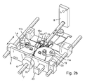
- the structural design of the lancing drive according to the FIGS. 2a and 2 B comprises two flywheels 11a and 11b, which are arranged symmetrically to both sides of the drive rod 7.
- the pressure piece 9 carries a transverse yoke 15, whose two opposite ends are connected by a respective connecting rod 8a and 8b with the flywheels 11a and 11b.
- the flywheels 11a, 11b have at their end faces teeth 16a, 16b, which engage with each other.
- the transverse yoke 15 is pivotally mounted by means of a rotary joint 17. This gives the mechanical system the necessary degree of freedom to run without inhibition even with a possible misalignment of the drive rod 7.
- flywheels 11a, 11b are formed in the manner of simple crankshafts, with a single crank arm and a respective crank pin 18a or 18b on which the crank rods 12a, 12b are mounted like connecting rods.
- left flywheel 11a is provided at the edge of a clamping stop 19.
- a clamping counter-stop 20 which is mounted outside of the sliding carriage 5 stationary in the device housing.
- the flywheel 11a is turned back, wherein the adhesive force between the stop element 13 and counter-stop 14 is overcome. In this way, the compression spring 10 can be tensioned.
- FIGS. 3a, b and c show an alternative embodiment of the drive mechanism.
- the drive rod 7 carries a pressure piece 9.
- a compression spring 10 presses against the underside of the pressure piece 9 so that the drive rod 7 is driven in the direction of the small arrow to the front.
- the lancing drive sits on a sliding carriage 5, which is relatively slowly displaceable in the direction of the large arrow.
- a cuboid flywheel 21 is displaceably mounted along a straight trajectory 22.
- a coupling rod 23 is rotatably mounted with its lower end on the flywheel 21, precisely in the middle.
- the upper end of the coupling rod 23 is rotatably mounted on the pressure piece 9.
- Flywheel 21 and coupling rod 23 form a passive co-rotating coupling gear, which converts the forward and backward movement of the drive rod 7 in a transverse movement of the flywheel 21 and vice versa.
- the movement path 22 extends transversely to the stitch axis.
- Fig. 3b has the drive rod 7 reaches its reversal point, which corresponds to the maximum penetration depth.
- the coupling rod 23 is vertical.
- the coupling gear is in the dead center.
- the compression spring 10 is deflected maximum.
- the flywheel 21 has maximum speed. Due to its inertial mass, the flywheel 21 continues to move in the direction of the transverse arrow transversely to the stitch axis. In this case, the right end of the flywheel approaches a limiting element which is fixedly mounted on the sliding carriage 5.
- Fig. 3c the fast retreat phase is just completed.
- the compression spring 10 is already compressed again a piece.
- the kinetic energy of the flywheel 21 was applied to the drive rod 7 and the lancet (cf. Fig. 1a ) shifted back.
- the lancing drive was stopped at the end by the flywheel 21 has struck with its right front side of the limiting element 24.
- the flywheel 21 is here made of ferromagnetic iron.
- the limiting element 24 is designed as a permanent magnet whose poles are closed by the flywheel 21, which acts as a magnetic armature. In the end position, therefore, the flywheel 21 and the limiting element 24 are held together by magnetic force. This sets the lancing drive.
- the further embodiment according to the Figures 4a, 4b and 4c differs from the embodiment described above only in that the trajectory 22 of the flywheel body 21 is not transversely, but obliquely with respect to the stitch axis by approximately 15 degrees.
- the coupling rod 23 is not vertical at top dead center, but is inclined by the same angle to the left, as in Fig. 4b to see. Since the center of the flywheel 21, which simultaneously forms the point of articulation for the coupling rod 23, moves downwards on an inclined path, less kinetic energy is required to accelerate the flywheel 21.
Abstract
Description
Die Erfindung betrifft ein Gerät zur Gewinnung einer Blutprobe, das eine Lanzette, einen Stechantrieb mit Antriebsfeder und eine Steuereinrichtung zur Steuerung der schnellen Einstich- und Rückzugsbewegung der Lanzette aufweist.The invention relates to a device for obtaining a blood sample, which has a lancet, a lancing drive with drive spring and a control device for controlling the rapid puncture and withdrawal movement of the lancet.
Ein solches Gerät dient vor allem Diabetikern zur regelmäßigen Selbstkontrolle des Blutzuckerspiegels. Dazu wird die Lanzette mit ihrer Spitze in die Haut eines Körperteils, vorzugsweise in die Fingerkuppe, getrieben. Aus der kleinen Wunde tritt dann eine kleine Menge Blut aus, die entweder unmittelbar oder durch eine Kapillare in der Lanzette aufgenommen wird. Anschließend kann diese Blutprobe analysiert werden.Such a device is used primarily for diabetics for regular self-monitoring of blood sugar levels. For this purpose, the lancet is driven with its tip into the skin of a body part, preferably in the fingertip. From the small wound then a small amount of blood comes out, which is taken either directly or through a capillary in the lancet. Subsequently, this blood sample can be analyzed.
Stand der Technik sind kleine automatische Handgeräte mit integrierter Messeinheit und als Mikronadel mit Kapillare ausgebildete Lanzette, die als Einwegartikel (Disposables) ausgebildet sind. Dabei ist ein Vorrat von Einweg-Lanzetten in einem Magazin gespeichert. Der Austausch einer benutzten Lanzette gegen eine neue erfolgt automatisch, so dass der Anwender nicht mit Einzelteilen hantieren muss.State of the art are small automatic handheld devices with integrated measuring unit and designed as a microneedle with capillary lancet, which are designed as disposable items (disposables). A stock of disposable lancets is stored in a magazine. The replacement of a used lancet A new one takes place automatically, so that the user does not have to handle individual parts.
Auch
Stechantriebe mit einer Antriebsfeder, deren Federkraft linear in Einstichrichtung direkt auf die Lanzette übertragen wird, sind konstruktiv einfach und damit ebenso zuverlässig wie kostengünstig und überdies platzsparend. Sie ermöglichen insbesondere den Einbau in ein schmales Handgerät, das vom Benutzer bequem und leibt handhabbar ist. Um einen möglichst schnellen und schmerzarmen Einstich zu gewährleisten, werden ziemlich starke Federn eingesetzt. Dabei besteht die Gefahr, dass durch ein Nachschwingen die Nadel mehrfach einsticht. Bei dem Blutentnahmesystem gemäß
Bei Microsampler-Stechgeräten, die einen Vorrat von Einmal-Lanzetten enthalten, muss neben dem eigentlichen Stechantrieb, der kurze schnelle Vor- und Rückbewegungen ausführt, zusätzlich auch ein Mechanismus vorgesehen werden, der vergleichsweise langsame, dafür lange Betätigungshübe bereitstellt, um die magazinierten Lanzetten an den Stechantrieb anzudocken und nach einmaliger Benutzung wieder frei zu geben.In the case of microsampler puncturers, which contain a supply of disposable lancets, a mechanism must additionally be provided in addition to the actual puncturing drive, which performs short, fast forward and backward movements be that comparatively slow, but long operating strokes provides to dock the magazinierten lancets to the lancing device and release after a single use again.
Stechantriebe, deren Steuereinrichtung mit einer Steuerkurve arbeitet, sind prinzipiell gut für abwechselnd schnelle und langsame Bewegungsphasen geeignet, haben aber bei großen Hüben den Nachteil, dass sie vergleichsweise groß sind, da anderenfalls die Steigungswinkel der Steuerkurve bis zur Selbsthemmung anwachsen. Dem kann dadurch begegnet werden, dass ein schneller kurzhubiger Stechantrieb, der die Lanzette antreibt, auf einen Schiebeschlitten montiert wird, der die großen langsamen Bewegungen für die Ineingriff- und Außereingriffnahme der Lanzette ausführt. Dieser Schiebeschlitten kann gleichzeitig auch dazu benutzt werden, den Stechantrieb zu spannen, beispielsweise indem der Stößel, der die Lanzette nach vorne treiben soll, gegen einen ortsfest im Gehäuse montierten Anschlag gefahren wird, bis die Antriebsfeder gespannt und im Auslösemechanismus verrastet ist. Solche so genannten "ballistischen" Antriebe bieten jedoch bisher keine Möglichkeit, nach dem Erreichen der maximalen Einstichtiefe schnell und ohne Nachschwingen eine definierte Position einzunehmen, die der Reststichtiefe entspricht. Dies ist aber sowohl für die Gewinnung einer ausreichenden Blutprobe wie auch die angestrebte Schmerzarmut wichtig. Wird der Stechantrieb einfach mit einem mechanischen Anschlag ausgerüstet, der die maximale Einstichtiefe begrenzt, so kommt es im Moment des tiefsten Einstichs zu einem harten Aufprall, was nicht nur ein irritierendes Geräusch verursacht, sondern auch eine Schwingung der Nadel auslöst, die zu erhöhtem Schmerzempfinden führt.Punches whose control device works with a cam are basically well suited for alternately fast and slow motion phases, but have the disadvantage of large strokes that they are relatively large, otherwise increase the pitch angle of the cam to self-locking. This can be counteracted by mounting a fast short-stroke lancing drive, which drives the lancet, on a sliding carriage that performs the large slow movements for engaging and disengaging the lancet. This sliding carriage can also be used at the same time to tension the lancing drive, for example, by the ram, which is to drive the lancet forward, is driven against a stationary mounted in the housing stop until the drive spring is tensioned and locked in the release mechanism. However, so-called "ballistic" drives so far offer no way to take a defined position after reaching the maximum penetration depth quickly and without ringing, which corresponds to the residual stitch depth. However, this is important both for obtaining a sufficient blood sample as well as the targeted pain relief. If the lancing device is simply equipped with a mechanical stop limiting the maximum penetration depth, a sharp impact occurs at the moment of the deepest puncture, which not only causes an irritating noise, but also causes the needle to vibrate, resulting in increased sensation of pain ,
Der vorliegenden Erfindung liegt somit das technische Problem zugrunde, einen konstruktiv einfachen Stechantrieb bereitzustellen, der mit einer einzigen, in Richtung der Bewegungsachse der Lanzette wirkenden Antriebsfeder auskommt und dennoch einen schwingungsfreien Einstich erlaubt. Insbesondere soll der Stechantrieb auch dazu geeignet sein, im Rahmen eines Schiebemechanismus, der zum langsamen vollständigen Rückzug der Lanzette, zum Andocken und Freigeben magazinierter Einmal-Lanzetten und/oder zum Spannen der Antriebsfeder dient, eingesetzt zu werden.The present invention is therefore based on the technical problem of providing a structurally simple lancing drive, which works with a single, acting in the direction of the axis of movement of the lancet drive spring and still allows a vibration-free puncture. In particular, the lancing drive should also be suitable, in the context of a sliding mechanism, for the slow complete retraction of the lancet, used for docking and releasing magazinated disposable lancets and / or for tensioning the drive spring, to be used.
Gelöst wird die gestellte Aufgabe gemäß dem kennzeichnenden Teil des ersten Patentanspruchs durch eine beweglich gelagerte Schwungmasse und ein Koppelglied, das die Schwungmasse an die Treibstange bzw. die Lanzette ankoppelt. Durch den Vortrieb der Lanzette wird die Schwungmasse in Bewegung versetzt. Dabei wird ein Teil der kinetischen Energie der Treibstange und der Lanzette zur Beschleunigung der Schwungmasse eingesetzt. Hat die Lanzette den Umkehrpunkt erreicht, der die maximale Einstichtiefe definiert, bewirkt die in der Schwungmasse gespeicherte Bewegungsenergie die Rückzugsbewegung der Lanzette. Dabei wird die aufgenommene kinetische Energie wieder auf die Treibstange und die angekoppelte Lanzette zurück übertragen. Durch die angekoppelte Schwungmasse lässt sich ein sanfter Übergang von der Vorwärts- in die Rückzugsbewegung der Lanzette realisieren und damit ein besonders schwingungsfreier schmerzarmer Einstich.The object is achieved according to the characterizing part of the first claim by a movably mounted flywheel and a coupling member which couples the flywheel to the drive rod or the lancet. By driving the lancet, the flywheel is set in motion. Part of the kinetic energy of the drive rod and the lancet is used to accelerate the flywheel. Once the lancet reaches the reversal point that defines the maximum puncture depth, the momentum stored in the flywheel causes the lancet to retract. The absorbed kinetic energy is transferred back to the drive rod and the attached lancet. The coupled flywheel allows a smooth transition from the forward to the return movement of the lancet realize and thus a particularly vibration-free pain-free puncture.
Bei einer bevorzugten Ausführung der Erfindung ist ein Koppelgetriebe vorgesehen, welches wenigstens einen, entlang einer linearen Bewegungsbahn bewegbaren Schwungkörper umfasst sowie eine Koppelstange, deren eines Ende mit der Treibstange verbunden ist und deren anderes Ende an dem Schwungkörper beweglich gelagert ist. Das Koppelgetriebe überträgt die Vorwärtsbewegung der Treibstange mit der angekoppelten Lanzette auf den Schwungkörper, der dadurch in eine translatorische Bewegung versetzt wird. Das Koppelgetriebe bewirkt nicht den Vortrieb der Lanzette, sondern läuft passiv mit. Die Kraft der sich entspannenden Feder wird nicht nur zum Antrieb der Lanzette benutzt, sondern gleichzeitig auch zur Beschleunigung des Schwungkörpers. Durchfährt die Lanzette den Umkehrpunkt, welcher der maximalen Einstichtiefe entspricht, so sorgt die träge Masse des Schwungkörpers dafür, dass er weiter in Bewegung bleibt. Diese fortgesetzte translatorische Bewegung überträgt sich durch die Koppelstange auf die Treibstange und leitet dadurch die Rückzugsbewegung der Lanzette ein. Dabei wird die in dem Schwungkörper gespeicherte Bewegungsenergie in kinetische Energie der Treibstange und der Lanzette umgesetzt. Das Koppelgetriebe steuert und begrenzt zudem die Einstichtiefe sehr präzise.In a preferred embodiment of the invention, a coupling mechanism is provided, which comprises at least one, along a linear movement path movable flywheel and a coupling rod, one end of which is connected to the drive rod and the other end is movably mounted on the flywheel. The coupling transmission transmits the forward movement of the drive rod with the coupled lancet on the flywheel body, which is thereby set in a translational movement. The coupling gear does not cause the propulsion of the lancet, but runs passively with. The power of the relaxing spring is not only used to drive the lancet, but also to accelerate the flywheel. If the lancet passes through the reversal point, which corresponds to the maximum penetration depth, the inertial mass of the flywheel body ensures that it continues to move. This continued translational movement is transmitted through the coupling rod to the drive rod and thereby initiates the withdrawal movement of the lancet. The kinetic energy stored in the flywheel body is transformed into kinetic energy the drive rod and the lancet implemented. The coupling gear also controls and limits the penetration depth very precisely.
Vorzugsweise verläuft die Bewegungsbahn des Schwungkörpers im Wesentlichen quer zur Stichachse der Lanzette. Bevorzugt ist die Bewegungsbahn eine Gerade. Dadurch, dass sich der Schwungkörper im Wesentlichen quer zur Stichachse bewegt, ist der Weg der Treibstange und damit der Lanzette in Vortriebsrichtung begrenzt. Ab dem Umkehrpunkt führt jede weitere Bewegung des Schwungkörpers zwangsweise dazu, dass sich die Treibstange und die Lanzette wieder nach unten bewegen müssen. Diese Kinematik lässt sich dazu benutzen, der Stichbewegung der Lanzette einen Übergang von der Vorwärts- in die Rückwärtsbewegung mit vorgegebenem Geschwindigkeitsprofil aufzuprägen. Das Geschwindigkeitsprofil, mit dem die Lanzette am Ende der Vorwärtsbewegung abgebremst und sofort anschließend wieder zurückgezogen wird, hängt entscheidend vom Verhältnis zwischen der trägen Masse des Schwungkörpers und der Federkraft der Antriebsfeder ab. Eine Feinabstimmung des Systems ist durch eine Veränderung der Masse des Schwungkörpers möglich.Preferably, the trajectory of the flywheel body is substantially transverse to the sting axis of the lancet. Preferably, the trajectory is a straight line. Because the flywheel body moves essentially transversely to the stitch axis, the travel of the drive rod and thus of the lancet in the drive direction is limited. From the point of reversal any further movement of the flywheel forcibly causes the drive rod and the lancet to move back down. This kinematics can be used to impart to the lancing movement of the lancet a transition from the forward to the backward movement with a given velocity profile. The speed profile, with which the lancet is decelerated at the end of the forward movement and immediately afterwards retracted, depends crucially on the relationship between the inertial mass of the flywheel body and the spring force of the drive spring. Fine tuning of the system is possible by changing the mass of the flywheel.
Verläuft die Bewegungsbahn des Schwungkörpers nicht rechtwinklig zur Stichachse, dann führt der Lagerpunkt der Koppelstange auf dem Schwungkörper eine Bewegung aus, die einen Anteil parallel zur Stichrichtung hat. Der parallel zur Stichachse wirkende Bewegungsanteil addiert sich dann zur Vor- bzw. Rückbewegung der Lanzette. Damit lässt sich das Verhältnis der kinetischen Energien, die von der Treibstange auf den Schwungkörper und umgekehrt übertragen werden, variieren. Zweckmäßig beträgt der Winkel, unter dem die Bewegungsbahn des Schwungkörpers schräg gegenüber der Stichachse verläuft, zwischen 5 und 45 Grad.If the movement path of the flywheel body does not run at right angles to the stitch axis, the bearing point of the coupling rod on the flywheel body executes a movement which has a portion parallel to the stitching direction. The movement component acting parallel to the stitch axis then adds to the forward or backward movement of the lancet. Thus, the ratio of the kinetic energies that are transmitted from the drive rod to the flywheel and vice versa, vary. Suitably, the angle at which the trajectory of the flywheel body runs obliquely with respect to the stitch axis is between 5 and 45 degrees.
Bewegt sich der Schwungkörper nicht entlang einer Geraden, sondern ist dessen Bewegungsbahn gekrümmt, so werden weitere Freiheitsgrade geschaffen, um das Geschwindigkeits- und/oder Beschleunigungsprofil der Lanzette speziell im Bereich der maximalen Einstichtiefe optimal zu gestalten.If the flywheel body does not move along a straight line, but if its movement path is curved, further degrees of freedom are created in order to optimize the speed and / or acceleration profile of the lancet, especially in the area of the maximum penetration depth.
Bei einer weiteren bevorzugten Ausführung der Erfindung ist ein Kurbeltrieb vorgesehen, welcher wenigstens ein drehbar gelagertes Schwungrad umfasst sowie eine Kurbelstange, deren eines Ende mit der Treibstange für die Lanzette verbunden und deren anderes Ende auf dem Schwungrad exzentrisch gelagert ist. Der Kurbeltrieb setzt die oszillierende translatorische Bewegung der Lanzette in eine rotatorische Bewegung des Schwungrads um, vergleichbar einer Kurbelwelle mit Pleuel bei einer Kolbenmaschine. Der Kurbeltrieb bewirkt nicht den Vortrieb der Lanzette, sondern steuert und begrenzt die Einstich- und Rückzugsbewegung der Lanzette. Wird die Lanzette durch die Spannkraft der Antriebsfeder nach vorne getrieben, so wird dadurch das Schwungrad in Rotation versetzt. Der obere Totpunkt des Kurbeltriebs definiert die maximale Einstichtiefe der Lanzette. Ist der obere Totpunkt überschritten, so bewirkt die in dem Schwungrad gespeicherte Rotationsenergie die Umkehr der Bewegungsrichtung der Lanzette und schließlich deren schneller Rückzug bis zur vorgegebenen Reststichtiefe. Das Geschwindigkeitsprofil, mit dem die Lanzette abgebremst und wieder zurückgezogen wird, hängt entscheidend vom Verhältnis zwischen der trägen Masse des Schwungrads und der Federkraft der Antriebsfeder ab. Eine Feinabstimmung des Systems ist durch eine Veränderung der Masse des Schwungrads auf einfache Weise möglich.In a further preferred embodiment of the invention, a crank mechanism is provided which comprises at least one rotatably mounted flywheel and a connecting rod, one end of which is connected to the drive rod for the lancet and the other end is mounted eccentrically on the flywheel. The crank mechanism converts the oscillating translational movement of the lancet into a rotational movement of the flywheel, comparable to a crankshaft with a connecting rod in a piston engine. The crank mechanism does not effect the propulsion of the lancet, but controls and limits the puncture and retraction movement of the lancet. If the lancet is driven forward by the tension of the drive spring, this causes the flywheel to rotate. The top dead center of the crank mechanism defines the maximum penetration depth of the lancet. If the top dead center is exceeded, the rotational energy stored in the flywheel effects the reversal of the direction of movement of the lancet and, finally, its rapid retraction up to the predetermined residual stitch depth. The speed profile used to decelerate and retract the lance depends critically on the relationship between the inertial mass of the flywheel and the spring force of the drive spring. Fine tuning of the system is easily possible by changing the mass of the flywheel.
Gegenüber Stechantrieben, bei denen der Vortrieb der Lanzette durch einen harten Anschlag begrenzt wird oder eine zweite Feder die Rückzugsbewegung übernimmt, wird bei der erfindungsgemäßen Konstruktion der obere Totpunkt durch die Umsetzung einer Kreisbewegung in eine translatorische Bewegung angesteuert, was automatisch zu einer nichtlinearen Charakteristik, d.h. zu einem weichen, aber präzise kontrollierten Bewegungsablauf führt.In contrast to puncturing drives, in which the propulsion of the lancet is limited by a hard stop or a second spring takes over the retraction movement, in the construction according to the invention the top dead center is driven by the implementation of a circular motion in a translational movement, which automatically leads to a non-linear characteristic, i. leads to a smooth but precisely controlled movement.
Vorzugsweise ist das Schwungrad quer zur Stichachse der Lanzette drehbar gelagert, so dass die Drehachse des Schwungrads und die Stichachse der Lanzette senkrecht zueinander stehen. An Stelle eines solchen gewöhnlichen Kurbeltriebs kann aber auch eine Anordnung verwendet werden, bei der die Drehachse des Schwungrads parallel zur Stichachse der Lanzette verläuft.Preferably, the flywheel is rotatably mounted transversely to the stub axle of the lancet, so that the axis of rotation of the flywheel and the stub axle of the lancet are perpendicular to each other. Instead of such an ordinary crank mechanism but also an arrangement may be used in which the axis of rotation of the flywheel runs parallel to the sting axis of the lancet.
Insbesondere bei sehr leichter Ausführung der Treibstange kann dadurch Bauraum gespart werden.In particular, with very light design of the drive rod thereby space can be saved.
Der vorgeschlagene Kurbeltrieb, bestehend aus Schwungrad und mit der Lanzette verbundener Kurbelstange, erzwingt ein Umkehren der Bewegungsrichtung der Lanzette im oberen Totpunkt unabhängig davon, ob in diesem Moment die Antriebsfeder schon vollständig entspannt ist oder diese gar schon überstreckt ist. Bevorzugt ist allerdings eine Ausführung, bei der die Rückzugsbewegung entgegen der Wirkung der noch nicht völlig entspannten Antriebsfeder erfolgt. Dabei wird die Federkraft zwar etwas früher in Rotationsenergie umgesetzt, jedoch wird durch die Rückzugsbewegung der Lanzette entgegen einer gewissen Rest-Spannkraft der Druckfeder die Gefahr einer Schwingung, die im Bereich der maximalen Einstichtiefe besonders störend wäre, zuverlässig vermieden.The proposed crank mechanism, consisting of flywheel and connected to the lancet crank rod, forces a reversal of the direction of movement of the lancet at top dead center regardless of whether at this moment the drive spring is already fully relaxed or this is already overstretched. However, an embodiment is preferred in which the return movement takes place against the action of the not yet completely relaxed drive spring. Although the spring force is converted into rotational energy somewhat earlier, the danger of oscillation, which would be particularly troublesome in the region of the maximum penetration depth, is reliably prevented by the return movement of the lancet against a certain residual tension force of the compression spring.
Der Einsatz eines Kurbeltriebs in einem Stechantrieb ist an sich bereits aus
Der Kurbeltrieb ist vorzugsweise seitlich versetzt zur Stichachse der Lanzette angeordnet. Das exzentrisch, vorzugsweise im Bereich des äußeren Randes des Schwungrads angeordnete Drehlager der Kurbelstange bewegt sich damit entlang eines Kreisbogens, so dass sich der seitliche Abstand zur Bewegungsachse der Lanzette während der Vor- und Rückbewegung der Lanzette ändert. Je größer der Abstand und damit der Winkel ist, unter dem die Kurbelstange an der Treibstange angreift, desto langsamer dreht sich das Schwungrad. Dies führt dazu, dass zu Beginn der Vortriebsphase das Schwungrad nur mäßig beschleunigt wird, kurz vor Erreichen des oberen Totpunkts jedoch sehr stark. Nach dem Umkehrpunkt der Lanzette sorgt die träge Masse des Schwungrads dafür, dass es sich weiterdreht. Der angekoppelte Kurbeltrieb mit Schwungrad sorgt also zuerst für eine starke Abbremsung der Lanzette kurz vor Erreichen der maximalen Einstichtiefe und bewirkt anschließend den schnellen Rückzug bis zur Reststichtiefe. Gleichzeitig definiert und begrenzt der Kurbeltrieb die Einstichtiefe.The crank mechanism is preferably arranged laterally offset from the stub axle of the lancet. The eccentric, preferably arranged in the region of the outer edge of the flywheel pivot bearing of the connecting rod thus moves along a circular arc, so that the lateral distance to the axis of movement of the lancet during the forward and backward movement of the lancet changes. The larger the distance and thus the angle at which the connecting rod engages the drive rod, the slower the flywheel rotates. This means that at the beginning of the propulsion phase, the flywheel is only moderately accelerated, but shortly before reaching top dead center very strong. After the reversal point of the lancet, the inertial mass of the flywheel ensures that it continues to rotate. The coupled crank drive with flywheel thus ensures first a strong deceleration of the lancet shortly before reaching the maximum penetration depth and then causes the rapid withdrawal to the residual stitch depth. At the same time, the crank mechanism defines and limits the penetration depth.
In vorteilhafter Weiterbildung der Erfindung ist die Antriebsfeder eine Schraubenfeder, vorzugsweise eine koaxial um die Treibstange angeordnete Druckfeder, ist auf der Treibstange ein Druckstück vorgesehen, gegen das die Druckfeder drückt, und ist die Kurbelstange des Kurbeltriebs über das Druckstück mit der Treibstange verbunden. Das Druckstück hat zwei Funktionen: Zum einen bildet es eine Anlagefläche für die Druckfeder und überträgt deren Federkraft auf die Treibstange, zum anderen bildet es einen Lagerblock für das obere Drehlager der Kurbelstange. Zweckmäßig wird man das Druckstück so bemessen, dass es seitlich über die Druckfeder hinaus auskragt, so dass die Kurbelstange in allen Bewegungsphasen ausreichenden Abstand zur Druckfeder hat. Damit kann die Kurbelstange relativ kurz ausgeführt werden, so dass der Stechantrieb kompakt bleibt.In an advantageous embodiment of the invention, the drive spring is a helical spring, preferably coaxially disposed around the drive rod compression spring, a pressure piece is provided on the drive rod against which presses the compression spring, and the connecting rod of the crank mechanism via the pressure piece with the drive rod. The pressure piece has two functions: First, it forms a contact surface for the compression spring and transmits its spring force on the drive rod, on the other hand, it forms a bearing block for the upper pivot bearing of the connecting rod. Appropriately, one will dimension the pressure piece so that it projects laterally beyond the compression spring out, so that the connecting rod has sufficient distance to the compression spring in all phases of movement. Thus, the connecting rod can be made relatively short, so that the lancing drive remains compact.
Nach der Rückzugsphase sollte die Lanzette möglichst schnell in der Position fixiert werden, die der vorgegebenen Reststichtiefe entspricht. Am einfachsten geschieht dies durch ein Anschlagelement, das sich mit dem Schwungrad mitdreht und bei einer vorgegebenen Winkelstellung auf ein festes Gegenanschlagelement trifft. Damit wird die Drehbewegung des Schwungrads am Ende der Rückzugsphase gestoppt und die Reststichtiefe definiert.After the withdrawal phase, the lancet should be fixed as quickly as possible in the position corresponding to the predetermined residual stitch depth. The easiest way to do this is by a stop element, which rotates with the flywheel and strikes a fixed counter-stop element at a predetermined angular position. Thus, the rotational movement of the flywheel is stopped at the end of the retraction phase and defined the residual stitch depth.
Damit sich nach Erreichen der Reststichtiefe die Lanzette auch nicht mehr nach vorne bewegen kann, was ja zu einem erneuten schmerzhaften Einstich führen würde, ist es zweckmäßig, das Anschlagelement an dem Gegenanschlagelement festzulegen. Bevorzugt geschieht dies durch Magnetkraft, so dass das Anschlagelement an dem Gegenanschlagelement magnetisch haftet. Die Magnetkraft sollte ausreichend groß sein, um den gesamten Stechantrieb festzulegen.Thus, after reaching the residual stitch depth, the lancet can not move forward, which would indeed lead to a renewed painful puncture, it is expedient to set the stop element on the counter-stop element. This is preferably done by magnetic force, so that the stop element adheres magnetically to the counter-stop element. The magnetic force should be large enough to set the entire lance drive.
Bei einem seitlichen Versatz zwischen Drehachse des Schwungrads und Stichachse der Lanzette wirken unweigerlich Querkräfte auf die Treibstange. Dadurch kann es zu störenden Reibungen in den Führungslagern kommen. Deshalb ist es vorteilhaft, den Kurbeltrieb symmetrisch aufzubauen, also zwei Schwungräder einander gegenüberliegend zu beiden Seiten der Treibstange anzuordnen. Das Druckstück auf der Treibstange kann dann ein Querjoch umfassen, so dass die beiden gegenüberliegenden Enden des Querjochs durch je eine Kurbelstange mit den Schwungrädern verbindbar sind. Die von den Kurbelstangen über das Druckstück auf die Treibstange übertragenen Seitenkräfte heben sich bei dieser symmetrischen Anordnung auf.In the case of a lateral offset between the axis of rotation of the flywheel and the stub axle of the lancet, transverse forces inevitably act on the drive rod. This can lead to disturbing friction in the guide bearings. Therefore, it is advantageous to construct the crank drive symmetrically, so to arrange two flywheels opposite each other on both sides of the drive rod. The pressure piece on the drive rod may then comprise a transverse yoke, so that the two opposite ends of the transverse yoke are connectable by a respective connecting rod with the flywheels. The transmitted from the connecting rods via the pressure piece on the drive rod side forces cancel each other in this symmetrical arrangement.
Die beiden Kurbeltriebe und insbesondere deren Schwungräder sind vorzugsweise miteinander zu synchronisieren, beispielsweise dadurch, dass die beiden Schwungräder an ihren Stirnseiten ineinander greifende Verzahnungen aufweisen. Um ein Verklemmen der beiden Kurbeltriebe zu verhindern, ist es zweckmäßig, die beiden spiegelbildlichen Kurbelstangen über ein weiteres Drehgelenk mit der Treibstange zu verbinden. Vorzugsweise geschieht dies durch ein Querjoch, das schwenkbeweglich an der Treibstange gelagert ist. Da hier nur sehr kleine Schwenkbewegungen auftreten, kann die erforderliche Beweglichkeit beispielsweise durch ein Filmscharnier hergestellt werden, wodurch der Fertigungsaufwand äußerst gering gehalten wird.The two crank mechanisms and in particular their flywheels are preferably to be synchronized with each other, for example, characterized in that the two flywheels have at their end faces intermeshing teeth. In order to prevent jamming of the two crank mechanisms, it is expedient to connect the two mirror-image crank rods via a further rotary joint with the drive rod. Preferably, this is done by a cross yoke, which is pivotally mounted on the drive rod. Since only very small pivoting movements occur here, the required mobility can be produced for example by a film hinge, whereby the production cost is kept extremely low.
Besonders bevorzugt wird eine Ausführung, bei welcher der Stechantrieb einschließlich Druckfeder und der Kurbeltrieb umfassend mindestens ein Schwungrad gemeinsam auf einem Schiebeschlitten angeordnet sind, der parallel zur Bewegungsachse der Lanzette verschieblich ist. Wird nämlich der Stechantrieb nach Erreichen der Reststichtiefe blockiert, so wird die Treibstange zu einem gegenüber dem Schiebeschlitten nicht mehr beweglichen Bauteil. Der Schiebeschlitten kann dann die langhubigen und langsamen Bewegungen ausführen, die zum vollständigen Rückzug der Lanzette dienen und über die blockierte Treibstange auf die Lanzette übertragen werden. Vorteilhaft kann der Schiebeschlitten auch zum Spannen des Stechantriebs benutzt werden, indem ein Spannanschlag an einem Schwungrad gegen einen ortsfesten Gegenanschlag gefahren wird.Particularly preferred is an embodiment in which the lancing drive including compression spring and the crank mechanism comprising at least one flywheel are arranged together on a sliding carriage, which is displaceable parallel to the axis of movement of the lancet. Namely, if the lancing drive is blocked after reaching the residual stitch depth, the drive rod becomes a relative to the sliding carriage no longer movable component. The sliding carriage can then perform the long-stroke and slow movements that serve to complete withdrawal of the lancet and be transferred to the lancet via the blocked drive rod. Advantageously, the sliding carriage can also be used for clamping the lancing drive by a tension stop on a flywheel is driven against a stationary counter-stop.
Ein Ausführungsbeispiel der Erfindung wird nachstehend anhand der beigefügten Zeichnungen beschrieben. Es zeigen:
- Figur 1a
- ein erstes Gerät zur Gewinnung einer Blutprobe, mit einem Kurbeltrieb und einem Schwungrad während der Vortriebsphase der Lanzette, in einem Prinzipbild;
- Figur 1b
- das Gerät von
Fig. 1a bei maximaler Einstichtiefe; - Figur 1c
- das Gerät nach
Fig. 1a bei Reststichtiefe; - Figur 2a
- ein zweites Gerät zur Gewinnung einer Blutprobe, mit zwei symmetrischen Kurbeltrieben und zwei Schwungrädern, in einer vereinfachten perspektivischen Ansicht von oben;
- Figur 2b
- das Gerät nach
Fig. 2a , von unten gesehen; - Figur 3a
- ein drittes Gerät zur Gewinnung einer Blutprobe, mit einem Koppelgetriebe und Schwungkörper während der Vortriebsphase der Lanzette, in einem Prinzipbild;
- Figur 3b
- das Gerät von
Fig. 3a bei maximaler Einstichtiefe; - Figur 3c
- das Gerät nach
Fig. 3a bei Reststichtiefe; - Figur 4a
- ein viertes Gerät zur Gewinnung einer Blutprobe, mit einem Koppelgetriebe und schräger Bewegungsbahn des Schwungkörpers während der Vortriebsphase der Lanzette, in einem Prinzipbild;
- Figur 4b
- das Gerät von
Fig. 4a bei maximaler Einstichtiefe; - Figur 4c
- das Gerät nach
Fig. 4a bei Reststichtiefe.
- FIG. 1a
- a first apparatus for obtaining a blood sample, with a crank mechanism and a flywheel during the propulsion phase of the lancet, in a schematic diagram;
- FIG. 1b
- the device of
Fig. 1a at maximum penetration depth; - Figure 1c
- the device after
Fig. 1a at residual stitch depth; - FIG. 2a
- a second apparatus for obtaining a blood sample, with two symmetrical crank gears and two flywheels, in a simplified perspective view from above;
- FIG. 2b
- the device after
Fig. 2a seen from below; - FIG. 3a
- a third device for obtaining a blood sample, with a coupling gear and flywheel body during the propulsion phase of the lancet, in a schematic diagram;
- FIG. 3b
- the device of
Fig. 3a at maximum penetration depth; - Figure 3c
- the device after
Fig. 3a at residual stitch depth; - FIG. 4a
- a fourth device for obtaining a blood sample, with a coupling gear and oblique trajectory of the flywheel body during the propulsion phase of the lancet, in a schematic diagram;
- FIG. 4b
- the device of
Fig. 4a at maximum penetration depth; - Figure 4c
- the device after
Fig. 4a at residual stitch depth.
In den Abbildungen sind gleiche Teile jeweils mit gleichen Bezugszeichen versehen.In the figures, the same parts are each provided with the same reference numerals.
Die Prinzipbilder der
Der Stechantrieb ist auf einen Schiebeschlitten 5 montiert, der langsame langhubige Bewegungen - angedeutet durch den langen Doppelpfeil - ausführen kann, um die Lanzette 1 nach einmaligem Gebrauch gegen ein neues Exemplar auszutauschen.The lancing drive is mounted on a sliding
Der Schiebeschlitten 5 trägt ein Gleitlager 6, in dem eine runde Treibstange 7 in axialer Richtung verschieblich so gelagert ist, dass die Treibstange 7 den Schiebeschlitten 5 durchsetzt. An ihrem oberen Ende weist die Treibstange 7 eine Kupplung 8 auf, mittels der die Lanzette 1 an die Treibstange 7 lösbar angekoppelt ist. In einigem Abstand unterhalb der Kupplung 8 ist an die Treibstange 7 ein Druckstück 9 fest anmontiert. Um die Treibstange 7 herum ist koaxial eine Druckfeder 10 angeordnet, deren unteres Ende am Schiebeschlitten 5 anliegt. Die Druckfeder 10 ist eine zylindrische Schraubenfeder aus Stahl mit linearer Federcharakteristik. Mit ihrem oberen Ende drückt die Druckfeder 10 gegen die Unterseite des Druckstücks 9, so dass sie die Treibstange 7 und die angekoppelte Lanzette 1 in Richtung des kleinen Pfeils nach vorne treibt. Die Bewegungsachse der Treibstange 7 mit der Lanzette 1 und die Bewegungsrichtung des Schiebeschlittens 5 sind zueinander parallel. In
Seitlich neben der Treibstange 7 ist ein Schwungrad 11 quer zur Bewegungsachse der Lanzette 1 drehbar gelagert. Eine Kurbelstange 12 ist mit ihrem einen Ende im Bereich des Randes des Schwungrads 11 drehbar gelagert, während das andere Ende der Kurbelstange 12 auf dem Druckstück 9 drehbar gelagert ist. Das Druckstück 9 kragt seitlich so weit aus, dass die Kurbelstange 12 nicht in Kontakt mit den Windungen der Druckfeder 10 gerät. Das Schwungrad 11 trägt ein mitbewegtes Anschlagelement 13, das in
Schwungrad 11 und Kurbelstange 12 bilden einen passiv mitlaufenden Kurbeltrieb, der die translatorische Bewegung der Treibstange 7 in eine Drehbewegung des Schwungrads 11 umsetzt. Dabei wird ein Teil der kinetischen Energie der Treibstange 7 und der angekoppelten Lanzette 1 in Rotationsenergie des Schwungrads 11 umgesetzt.
In
In
Das Gegenanschlagelement 14 ist hier als Permanentmagnet ausgebildet, dessen Pole durch das Anschlagelement 13, das als magnetischer Anker ausgebildet ist, geschlossen werden. In der Endstellung werden also Anschlagelement 13 und Gegenanschlag 14 durch Magnetkraft aufeinander gehalten. Damit ist der Stechantrieb festgelegt. Ein Zurückschwingen der Lanzette 1 mit der Gefahr eines nochmaligen Einstiches ist dadurch ausgeschlossen.The
Die konstruktive Ausgestaltung des Stechantriebs gemäß den
In
Befinden sich die Schwungräder 11a, 11b in ihrer Endstellung, die der Reststichtiefe entspricht, sind diese durch das Aneinanderhaften von Anschlagelement 13 und Gegenanschlag 14 (vgl.
Auf dem in
Die Prinzipbilder der
Die Treibstange 7 trägt ein Druckstück 9. Eine Druckfeder 10 drückt gegen die Unterseite des Druckstücks 9 so, dass die Treibstange 7 in Richtung des kleinen Pfeils nach vorne getrieben wird. Der Stechantrieb sitzt auf einem Schiebeschlitten 5, der in Richtung des großen Pfeils relativ langsam verschieblich ist.The
Ein quaderförmiger Schwungkörper 21 ist entlang einer geraden Bewegungsbahn 22 verschieblich gelagert. Eine Koppelstange 23 ist mit ihrem unteren Ende auf dem Schwungkörper 21 drehbar gelagert, und zwar genau in der Mitte. Das obere Ende der Koppelstange 23 ist auf dem Druckstück 9 drehbar gelagert. Schwungkörper 21 und Koppelstange 23 bilden ein passiv mitlaufendes Koppelgetriebe, das die Vor- und Rückbewegung der Treibstange 7 in eine Querbewegung des Schwungkörpers 21 umsetzt und umgekehrt. Die Bewegungsbahn 22 verläuft quer zur Stichachse.A
In
In
In
Der Schwungkörper 21 ist hier aus ferromagnetischem Eisen hergestellt. Das Begrenzungselement 24 ist als Permanentmagnet ausgebildet, dessen Pole durch den Schwungkörper 21, der als magnetischere Anker wirkt, geschlossen werden. In der Endstellung werden also der Schwungkörper 21 und das Begrenzungselement 24 durch Magnetkraft aufeinander gehalten. Damit ist der Stechantrieb festgelegt.The
Die weitere Ausführungsform gemäß den
- 11
- Lanzettelancet
- 22
- Stechspitzepiercing tip
- 33
- Kapillarkanalcapillary
- 44
- BlutsammelraumBlood collection chamber
- 55
- Schiebeschlittensliding table
- 66
- Gleitlagerbearings
- 77
- Treibstangedriving rod
- 88th
- Kupplungclutch
- 99
- DruckstückPressure piece
- 1010
- Druckfedercompression spring
- 1111
- Schwungradflywheel
- 11a, 11b11a, 11b
- Schwungräderflywheels
- 1212
- Kurbelstangeconnecting rod
- 12a, 12b12a, 12b
- Kurbelstangenconnecting rods
- 1313
- Anschlagelementstop element
- 1414
- Gegenanschlagcounterstop
- 1515
- Querjochcrosshead
- 16a, 16b16a, 16b
- Verzahnungen (an 11a, 11b)Gears (at 11a, 11b)
- 1717
- Drehgelenkswivel
- 18a, 18b18a, 18b
- Kurbelzapfencrank pin
- 1919
- Spannanschlag (an 11a)Tension stop (at 11a)
- 2020
- SpanngegenanschlagClamping counter-stop
- 2121
- Schwungkörperflywheel body
- 2222
- Bewegungsbahn (von 21)Trajectory (from 21)
- 2323
- Koppelstangecoupling rod
- 2424
- Begrenzungselementlimiting element
Claims (18)
einer Lanzette, die in einer kontrollierten Vor- und Rückbewegung in die Haut eines Körperteils eingestochen und sofort anschließend wieder ein Stück zurückgezogen wird, um das aus der Wunde austretende Blut aufzunehmen,
einem Stechantrieb umfassend eine an die Lanzette angekoppelte Treibstange und eine in Richtung der Stichachse der Lanzette wirkende Antriebsfeder,
einer Steuereinrichtung zur Steuerung der Einstich- und Rückzugsbewegung der Lanzette gemäß einem vorgegebenen Bewegungsprofil umfassend zumindest eine schnelle Vortriebsphase, bei der die Lanzette bis zu einer vorgegebenen maximalen Einstichtiefe eingestochen wird, und eine schnelle Rückzugsphase, bei der die Lanzette bis zu einer vorgegebenen Reststichtiefe teilweise wieder zurückgezogen wird,
gekennzeichnet durch
eine beweglich gelagerte Schwungmasse und ein Koppelglied, das die Schwungmasse an die Treibstange (7) derart ankoppelt, dass der Vortrieb der Lanzette (1) die Schwungmasse in Bewegung versetzt und nach Erreichen der maximalen Einstichtiefe die in der Schwungmasse gespeicherte Bewegungsenergie die Rückzugsbewegung der Lanzette (1) bewirkt.Apparatus for obtaining a blood sample, with
a lancet, which is inserted into the skin of a body part in a controlled forward and backward movement and then immediately withdrawn a little bit to absorb the blood leaving the wound,
a lancing drive comprising a drive rod coupled to the lancet and a drive spring acting in the direction of the sting axis of the lancet,
a control device for controlling the puncturing and retracting movement of the lancet according to a predetermined movement profile comprising at least one fast advancing phase, in which the lancet is inserted to a predetermined maximum penetration depth, and a rapid withdrawal phase, in which the lancet partially to a predetermined residual stitch depth again is withdrawn,
marked by
a movably mounted flywheel and a coupling member, which couples the flywheel to the drive rod (7) such that the propulsion of the lancet (1) sets the flywheel in motion and after reaching the maximum penetration depth the kinetic energy stored in the flywheel, the retraction movement of the lancet ( 1) causes.
einen Kurbeltrieb umfassend wenigstens ein drehbar gelagertes Schwungrad (11) und eine Kurbelstange (12), deren eines Ende mit der Treibstange (7) verbunden ist und deren anderes Ende an dem Schwungrad (11) exzentrisch gelagert ist,
so dass der Vortrieb der Lanzette (1) das Schwungrad (11) in Rotation versetzt und nach Überwindung des oberen Totpunkts, der die maximale Einstichtiefe definiert, die in dem Schwungrad (11) gespeicherte Rotationsenergie die Rückzugsbewegung der Lanzette (1) bewirkt.Apparatus according to claim 1, characterized by
a crank mechanism comprising at least one rotatably mounted flywheel (11) and a crank rod (12), one end of which is connected to the drive rod (7) and whose other end is mounted eccentrically on the flywheel (11),
such that the propulsion of the lancet (1) causes the flywheel (11) to rotate and, after overcoming the top dead center defining the maximum penetration depth, the rotational energy stored in the flywheel (11) causes the lancet (1) to retract.
die Antriebsfeder eine koaxial um die Treibstange (7) angeordnete Druckfeder (10) ist,
auf der Treibstange (7) ein Druckstück (9) vorgesehen ist, gegen das die Druckfeder (10) drückt,
die Kurbelstange (12) über das Druckstück (9) mit der Treibstange (7) verbunden ist.Device according to one of claims 6 to 9, characterized in that
the drive spring is a compression spring (10) arranged coaxially around the drive rod (7),
on the drive rod (7) a pressure piece (9) is provided against which the compression spring (10) presses,
the connecting rod (12) is connected to the drive rod (7) via the pressure piece (9).
zwei Schwungräder (11a, 11b) einander gegenüberliegend zu beiden Seiten der Treibstange (7) angeordnet sind,
an der Treibstange (7) ein Querjoch (15) angeordnet ist,
die beiden gegenüberliegenden Enden des Querjochs (15) durch je eine Kurbelstange (12a, 12b) mit den Schwungrädern (11a, 11b) verbunden sind.Device according to one of claims 6 to 12, characterized in that
two flywheels (11a, 11b) are arranged opposite one another on both sides of the drive rod (7),
on the drive rod (7) a transverse yoke (15) is arranged,
the two opposite ends of the transverse yoke (15) are each connected by a connecting rod (12a, 12b) to the flywheels (11a, 11b).
Priority Applications (3)
| Application Number | Priority Date | Filing Date | Title |
|---|---|---|---|
| EP08170441A EP2193746B8 (en) | 2008-12-02 | 2008-12-02 | Device to obtain a blood sample |
| AT08170441T ATE542478T1 (en) | 2008-12-02 | 2008-12-02 | DEVICE FOR OBTAINING A BLOOD SAMPLE |
| US12/627,420 US8317813B2 (en) | 2008-12-02 | 2009-11-30 | Device for acquiring a blood sample |
Applications Claiming Priority (1)
| Application Number | Priority Date | Filing Date | Title |
|---|---|---|---|
| EP08170441A EP2193746B8 (en) | 2008-12-02 | 2008-12-02 | Device to obtain a blood sample |
Publications (3)
| Publication Number | Publication Date |
|---|---|
| EP2193746A1 true EP2193746A1 (en) | 2010-06-09 |
| EP2193746B1 EP2193746B1 (en) | 2012-01-25 |
| EP2193746B8 EP2193746B8 (en) | 2012-03-28 |
Family
ID=40602331
Family Applications (1)
| Application Number | Title | Priority Date | Filing Date |
|---|---|---|---|
| EP08170441A Not-in-force EP2193746B8 (en) | 2008-12-02 | 2008-12-02 | Device to obtain a blood sample |
Country Status (3)
| Country | Link |
|---|---|
| US (1) | US8317813B2 (en) |
| EP (1) | EP2193746B8 (en) |
| AT (1) | ATE542478T1 (en) |
Families Citing this family (5)
| Publication number | Priority date | Publication date | Assignee | Title |
|---|---|---|---|---|
| SG154343A1 (en) * | 2008-01-08 | 2009-08-28 | Ting Choon Meng | Method and apparatus for intra-articular injection or aspiration |
| US9717452B2 (en) | 2010-12-30 | 2017-08-01 | Roche Diabetes Care, Inc. | Handheld medical diagnostic devices with lancing speed control |
| DE102011015758B4 (en) * | 2011-03-31 | 2013-08-01 | Gerresheimer Regensburg Gmbh | Lancing device with rotary element |
| US9486187B2 (en) * | 2013-09-26 | 2016-11-08 | Covidien Lp | Wind up deployment mechanisms for surgical instruments |
| CN113057846B (en) * | 2020-09-25 | 2022-08-09 | 江西应用科技学院 | Horizontal upper limb rehabilitation physiotherapy method and device |
Citations (8)
| Publication number | Priority date | Publication date | Assignee | Title |
|---|---|---|---|---|
| EP0036443B1 (en) | 1980-03-22 | 1986-03-05 | Roche Diagnostics GmbH | Lancet apparatus for withdrawing blood for diagnostic purposes |
| US4924879A (en) | 1988-10-07 | 1990-05-15 | Brien Walter J O | Blood lancet device |
| US6206901B1 (en) | 1999-09-06 | 2001-03-27 | Wlodzimierz Rutynowski | Puncturing device |
| EP1090584A2 (en) * | 1999-10-09 | 2001-04-11 | Roche Diagnostics GmbH | Blood lancet device for obtaining blood samples for diagnosis purposes |
| US20050131441A1 (en) * | 2003-12-16 | 2005-06-16 | Toshiaki Iio | Lancet for blood collection and puncture needle unit |
| WO2007073870A2 (en) | 2005-12-15 | 2007-07-05 | Roche Diagnostics Gmbh | Piercing system for removing a sample of bodily fluid |
| US20070213682A1 (en) * | 2006-03-13 | 2007-09-13 | Hans-Peter Haar | Penetration device, kit, and method |
| EP1852069A1 (en) | 2006-05-04 | 2007-11-07 | Roche Diagnostics GmbH | System for sampling blood from a body part |
Family Cites Families (9)
| Publication number | Priority date | Publication date | Assignee | Title |
|---|---|---|---|---|
| US623531A (en) * | 1899-04-25 | duncan | ||
| US5035704A (en) * | 1989-03-07 | 1991-07-30 | Lambert Robert D | Blood sampling mechanism |
| JP3097600B2 (en) * | 1997-05-30 | 2000-10-10 | 日本電気株式会社 | Stratum corneum puncture device |
| US5938679A (en) * | 1997-10-14 | 1999-08-17 | Hewlett-Packard Company | Apparatus and method for minimally invasive blood sampling |
| US6231531B1 (en) | 1999-04-09 | 2001-05-15 | Agilent Technologies, Inc. | Apparatus and method for minimizing pain perception |
| EP1764037A1 (en) * | 2005-09-15 | 2007-03-21 | F.Hoffmann-La Roche Ag | Device for extracting body liquids for the purpose of analysis |
| US20080019870A1 (en) * | 2006-07-21 | 2008-01-24 | Michael John Newman | Integrated medical device dispensing and lancing mechanisms and methods of use |
| US8118824B2 (en) * | 2008-09-16 | 2012-02-21 | Roche Diagnostics Operations, Inc. | Magnetic powered lancing drive |
| EP2311373B1 (en) * | 2009-10-15 | 2012-08-01 | Roche Diagnostics GmbH | Piercing system for removal of a body fluid |
-
2008
- 2008-12-02 AT AT08170441T patent/ATE542478T1/en active
- 2008-12-02 EP EP08170441A patent/EP2193746B8/en not_active Not-in-force
-
2009
- 2009-11-30 US US12/627,420 patent/US8317813B2/en active Active
Patent Citations (8)
| Publication number | Priority date | Publication date | Assignee | Title |
|---|---|---|---|---|
| EP0036443B1 (en) | 1980-03-22 | 1986-03-05 | Roche Diagnostics GmbH | Lancet apparatus for withdrawing blood for diagnostic purposes |
| US4924879A (en) | 1988-10-07 | 1990-05-15 | Brien Walter J O | Blood lancet device |
| US6206901B1 (en) | 1999-09-06 | 2001-03-27 | Wlodzimierz Rutynowski | Puncturing device |
| EP1090584A2 (en) * | 1999-10-09 | 2001-04-11 | Roche Diagnostics GmbH | Blood lancet device for obtaining blood samples for diagnosis purposes |
| US20050131441A1 (en) * | 2003-12-16 | 2005-06-16 | Toshiaki Iio | Lancet for blood collection and puncture needle unit |
| WO2007073870A2 (en) | 2005-12-15 | 2007-07-05 | Roche Diagnostics Gmbh | Piercing system for removing a sample of bodily fluid |
| US20070213682A1 (en) * | 2006-03-13 | 2007-09-13 | Hans-Peter Haar | Penetration device, kit, and method |
| EP1852069A1 (en) | 2006-05-04 | 2007-11-07 | Roche Diagnostics GmbH | System for sampling blood from a body part |
Also Published As
| Publication number | Publication date |
|---|---|
| ATE542478T1 (en) | 2012-02-15 |
| EP2193746B1 (en) | 2012-01-25 |
| EP2193746B8 (en) | 2012-03-28 |
| US20100152759A1 (en) | 2010-06-17 |
| US8317813B2 (en) | 2012-11-27 |
Similar Documents
| Publication | Publication Date | Title |
|---|---|---|
| EP1852069B1 (en) | System for sampling blood from a body part | |
| DE102004059491B4 (en) | Lancet device for creating a puncture wound and lancet drive assembly | |
| EP1884191B1 (en) | Lancet system | |
| EP1648540B1 (en) | Injection device | |
| DE60317997T2 (en) | lancet | |
| EP1631337B1 (en) | Insertion device for infusion sets | |
| EP2213229B1 (en) | Blood removal system | |
| EP1797822A1 (en) | Lancing system for sampling of bodily fluid | |
| EP1924200B1 (en) | Device for obtaining bodily fluids for analysis purposes | |
| EP2193746B1 (en) | Device to obtain a blood sample | |
| DE202009003009U1 (en) | Injection device with injection volume adjustment | |
| EP2429768B1 (en) | Setting tool | |
| EP3377312B1 (en) | Mechanical press with sliding block | |
| WO2018011356A1 (en) | Drive device for a moveable furniture part and method for opening and closing a moveable furniture part | |
| EP2925190B1 (en) | Device for moving a movable furniture part | |
| DE102009025444A1 (en) | Lancing device with lancet ejection means | |
| EP2311373B1 (en) | Piercing system for removal of a body fluid | |
| DE202009003050U1 (en) | Needle puncture device for medical devices | |
| EP2563223B1 (en) | Lancing device with automatic disengagement | |
| DE3625695A1 (en) | METHOD AND DEVICE FOR METAL MIRROR CRYOFIXATION OF BIOLOGICAL-MEDICAL OR SIMILAR TECHNICAL OBJECTS | |
| WO2014180777A1 (en) | Lever mechanism between a pre-stressing arrangement and a flywheel, for acting on a ram of a placement device | |
| DE102015222995A1 (en) | Weggebundene press with sliding block | |
| DE102004064136B4 (en) | Lancet device for making puncture wound for taking out body fluid for diagnostic purpose has reference element coupling mechanism with lancet drive for moving reference element and cam which is driven by cam rider | |
| DE2259229A1 (en) | NEEDLE APPARATUS FOR MEDICAL PURPOSES |
Legal Events
| Date | Code | Title | Description |
|---|---|---|---|
| PUAI | Public reference made under article 153(3) epc to a published international application that has entered the european phase |
Free format text: ORIGINAL CODE: 0009012 |
|
| AK | Designated contracting states |
Kind code of ref document: A1 Designated state(s): AT BE BG CH CY CZ DE DK EE ES FI FR GB GR HR HU IE IS IT LI LT LU LV MC MT NL NO PL PT RO SE SI SK TR |
|
| AX | Request for extension of the european patent |
Extension state: AL BA MK RS |
|
| 17P | Request for examination filed |
Effective date: 20100625 |
|
| AKX | Designation fees paid |
Designated state(s): AT BE BG CH CY CZ DE DK EE ES FI FR GB GR HR HU IE IS IT LI LT LU LV MC MT NL NO PL PT RO SE SI SK TR |
|
| GRAP | Despatch of communication of intention to grant a patent |
Free format text: ORIGINAL CODE: EPIDOSNIGR1 |
|
| GRAS | Grant fee paid |
Free format text: ORIGINAL CODE: EPIDOSNIGR3 |
|
| 17Q | First examination report despatched |
Effective date: 20111107 |
|
| GRAA | (expected) grant |
Free format text: ORIGINAL CODE: 0009210 |
|
| AK | Designated contracting states |
Kind code of ref document: B1 Designated state(s): AT BE BG CH CY CZ DE DK EE ES FI FR GB GR HR HU IE IS IT LI LT LU LV MC MT NL NO PL PT RO SE SI SK TR |
|
| REG | Reference to a national code |
Ref country code: GB Ref legal event code: FG4D Free format text: NOT ENGLISH |
|
| REG | Reference to a national code |
Ref country code: CH Ref legal event code: EP |
|
| RAP2 | Party data changed (patent owner data changed or rights of a patent transferred) |
Owner name: F. HOFFMANN-LA ROCHE AG Owner name: ROCHE DIAGNOSTICS GMBH |
|
| REG | Reference to a national code |
Ref country code: AT Ref legal event code: REF Ref document number: 542478 Country of ref document: AT Kind code of ref document: T Effective date: 20120215 |
|
| REG | Reference to a national code |
Ref country code: IE Ref legal event code: FG4D |
|
| REG | Reference to a national code |
Ref country code: DE Ref legal event code: R096 Ref document number: 502008006178 Country of ref document: DE Effective date: 20120322 |
|
| REG | Reference to a national code |
Ref country code: DE Ref legal event code: R081 Ref document number: 502008006178 Country of ref document: DE Owner name: ROCHE DIABETES CARE GMBH, DE Free format text: FORMER OWNERS: ROCHE DIAGNOSTICS GMBH, 68305 MANNHEIM, DE; F. HOFFMANN-LA ROCHE AG, 4070 BASEL, CH |
|
| REG | Reference to a national code |
Ref country code: NL Ref legal event code: VDEP Effective date: 20120125 |
|
| LTIE | Lt: invalidation of european patent or patent extension |
Effective date: 20120125 |
|
| PG25 | Lapsed in a contracting state [announced via postgrant information from national office to epo] |
Ref country code: BG Free format text: LAPSE BECAUSE OF FAILURE TO SUBMIT A TRANSLATION OF THE DESCRIPTION OR TO PAY THE FEE WITHIN THE PRESCRIBED TIME-LIMIT Effective date: 20120425 Ref country code: LT Free format text: LAPSE BECAUSE OF FAILURE TO SUBMIT A TRANSLATION OF THE DESCRIPTION OR TO PAY THE FEE WITHIN THE PRESCRIBED TIME-LIMIT Effective date: 20120125 Ref country code: HR Free format text: LAPSE BECAUSE OF FAILURE TO SUBMIT A TRANSLATION OF THE DESCRIPTION OR TO PAY THE FEE WITHIN THE PRESCRIBED TIME-LIMIT Effective date: 20120125 Ref country code: NL Free format text: LAPSE BECAUSE OF FAILURE TO SUBMIT A TRANSLATION OF THE DESCRIPTION OR TO PAY THE FEE WITHIN THE PRESCRIBED TIME-LIMIT Effective date: 20120125 Ref country code: NO Free format text: LAPSE BECAUSE OF FAILURE TO SUBMIT A TRANSLATION OF THE DESCRIPTION OR TO PAY THE FEE WITHIN THE PRESCRIBED TIME-LIMIT Effective date: 20120425 Ref country code: IS Free format text: LAPSE BECAUSE OF FAILURE TO SUBMIT A TRANSLATION OF THE DESCRIPTION OR TO PAY THE FEE WITHIN THE PRESCRIBED TIME-LIMIT Effective date: 20120525 |
|
| REG | Reference to a national code |
Ref country code: IE Ref legal event code: FD4D |
|
| PG25 | Lapsed in a contracting state [announced via postgrant information from national office to epo] |
Ref country code: PT Free format text: LAPSE BECAUSE OF FAILURE TO SUBMIT A TRANSLATION OF THE DESCRIPTION OR TO PAY THE FEE WITHIN THE PRESCRIBED TIME-LIMIT Effective date: 20120525 Ref country code: LV Free format text: LAPSE BECAUSE OF FAILURE TO SUBMIT A TRANSLATION OF THE DESCRIPTION OR TO PAY THE FEE WITHIN THE PRESCRIBED TIME-LIMIT Effective date: 20120125 Ref country code: PL Free format text: LAPSE BECAUSE OF FAILURE TO SUBMIT A TRANSLATION OF THE DESCRIPTION OR TO PAY THE FEE WITHIN THE PRESCRIBED TIME-LIMIT Effective date: 20120125 Ref country code: FI Free format text: LAPSE BECAUSE OF FAILURE TO SUBMIT A TRANSLATION OF THE DESCRIPTION OR TO PAY THE FEE WITHIN THE PRESCRIBED TIME-LIMIT Effective date: 20120125 Ref country code: GR Free format text: LAPSE BECAUSE OF FAILURE TO SUBMIT A TRANSLATION OF THE DESCRIPTION OR TO PAY THE FEE WITHIN THE PRESCRIBED TIME-LIMIT Effective date: 20120426 |
|
| PG25 | Lapsed in a contracting state [announced via postgrant information from national office to epo] |
Ref country code: CY Free format text: LAPSE BECAUSE OF FAILURE TO SUBMIT A TRANSLATION OF THE DESCRIPTION OR TO PAY THE FEE WITHIN THE PRESCRIBED TIME-LIMIT Effective date: 20120125 |
|
| PG25 | Lapsed in a contracting state [announced via postgrant information from national office to epo] |
Ref country code: EE Free format text: LAPSE BECAUSE OF FAILURE TO SUBMIT A TRANSLATION OF THE DESCRIPTION OR TO PAY THE FEE WITHIN THE PRESCRIBED TIME-LIMIT Effective date: 20120125 Ref country code: SE Free format text: LAPSE BECAUSE OF FAILURE TO SUBMIT A TRANSLATION OF THE DESCRIPTION OR TO PAY THE FEE WITHIN THE PRESCRIBED TIME-LIMIT Effective date: 20120125 Ref country code: CZ Free format text: LAPSE BECAUSE OF FAILURE TO SUBMIT A TRANSLATION OF THE DESCRIPTION OR TO PAY THE FEE WITHIN THE PRESCRIBED TIME-LIMIT Effective date: 20120125 Ref country code: IE Free format text: LAPSE BECAUSE OF FAILURE TO SUBMIT A TRANSLATION OF THE DESCRIPTION OR TO PAY THE FEE WITHIN THE PRESCRIBED TIME-LIMIT Effective date: 20120125 Ref country code: DK Free format text: LAPSE BECAUSE OF FAILURE TO SUBMIT A TRANSLATION OF THE DESCRIPTION OR TO PAY THE FEE WITHIN THE PRESCRIBED TIME-LIMIT Effective date: 20120125 Ref country code: RO Free format text: LAPSE BECAUSE OF FAILURE TO SUBMIT A TRANSLATION OF THE DESCRIPTION OR TO PAY THE FEE WITHIN THE PRESCRIBED TIME-LIMIT Effective date: 20120125 Ref country code: SI Free format text: LAPSE BECAUSE OF FAILURE TO SUBMIT A TRANSLATION OF THE DESCRIPTION OR TO PAY THE FEE WITHIN THE PRESCRIBED TIME-LIMIT Effective date: 20120125 |
|
| PG25 | Lapsed in a contracting state [announced via postgrant information from national office to epo] |
Ref country code: IT Free format text: LAPSE BECAUSE OF FAILURE TO SUBMIT A TRANSLATION OF THE DESCRIPTION OR TO PAY THE FEE WITHIN THE PRESCRIBED TIME-LIMIT Effective date: 20120125 Ref country code: SK Free format text: LAPSE BECAUSE OF FAILURE TO SUBMIT A TRANSLATION OF THE DESCRIPTION OR TO PAY THE FEE WITHIN THE PRESCRIBED TIME-LIMIT Effective date: 20120125 |
|
| PLBE | No opposition filed within time limit |
Free format text: ORIGINAL CODE: 0009261 |
|
| STAA | Information on the status of an ep patent application or granted ep patent |
Free format text: STATUS: NO OPPOSITION FILED WITHIN TIME LIMIT |
|
| 26N | No opposition filed |
Effective date: 20121026 |
|
| REG | Reference to a national code |
Ref country code: DE Ref legal event code: R097 Ref document number: 502008006178 Country of ref document: DE Effective date: 20121026 |
|
| PG25 | Lapsed in a contracting state [announced via postgrant information from national office to epo] |
Ref country code: ES Free format text: LAPSE BECAUSE OF FAILURE TO SUBMIT A TRANSLATION OF THE DESCRIPTION OR TO PAY THE FEE WITHIN THE PRESCRIBED TIME-LIMIT Effective date: 20120506 |
|
| BERE | Be: lapsed |
Owner name: F. HOFFMANN-LA ROCHE A.G. Effective date: 20121231 |
|
| PG25 | Lapsed in a contracting state [announced via postgrant information from national office to epo] |
Ref country code: MC Free format text: LAPSE BECAUSE OF NON-PAYMENT OF DUE FEES Effective date: 20121231 |
|
| REG | Reference to a national code |
Ref country code: CH Ref legal event code: PL |
|
| GBPC | Gb: european patent ceased through non-payment of renewal fee |
Effective date: 20121202 |
|
| REG | Reference to a national code |
Ref country code: FR Ref legal event code: ST Effective date: 20130830 |
|
| PG25 | Lapsed in a contracting state [announced via postgrant information from national office to epo] |
Ref country code: BE Free format text: LAPSE BECAUSE OF NON-PAYMENT OF DUE FEES Effective date: 20121231 |
|
| PG25 | Lapsed in a contracting state [announced via postgrant information from national office to epo] |
Ref country code: LI Free format text: LAPSE BECAUSE OF NON-PAYMENT OF DUE FEES Effective date: 20121231 Ref country code: CH Free format text: LAPSE BECAUSE OF NON-PAYMENT OF DUE FEES Effective date: 20121231 |
|
| PG25 | Lapsed in a contracting state [announced via postgrant information from national office to epo] |
Ref country code: MT Free format text: LAPSE BECAUSE OF FAILURE TO SUBMIT A TRANSLATION OF THE DESCRIPTION OR TO PAY THE FEE WITHIN THE PRESCRIBED TIME-LIMIT Effective date: 20120125 Ref country code: GB Free format text: LAPSE BECAUSE OF NON-PAYMENT OF DUE FEES Effective date: 20121202 Ref country code: FR Free format text: LAPSE BECAUSE OF NON-PAYMENT OF DUE FEES Effective date: 20130102 |
|
| PG25 | Lapsed in a contracting state [announced via postgrant information from national office to epo] |
Ref country code: TR Free format text: LAPSE BECAUSE OF FAILURE TO SUBMIT A TRANSLATION OF THE DESCRIPTION OR TO PAY THE FEE WITHIN THE PRESCRIBED TIME-LIMIT Effective date: 20120125 |
|
| PG25 | Lapsed in a contracting state [announced via postgrant information from national office to epo] |
Ref country code: LU Free format text: LAPSE BECAUSE OF NON-PAYMENT OF DUE FEES Effective date: 20121202 |
|
| PG25 | Lapsed in a contracting state [announced via postgrant information from national office to epo] |
Ref country code: HU Free format text: LAPSE BECAUSE OF FAILURE TO SUBMIT A TRANSLATION OF THE DESCRIPTION OR TO PAY THE FEE WITHIN THE PRESCRIBED TIME-LIMIT Effective date: 20081202 |
|
| REG | Reference to a national code |
Ref country code: AT Ref legal event code: MM01 Ref document number: 542478 Country of ref document: AT Kind code of ref document: T Effective date: 20131202 |
|
| PG25 | Lapsed in a contracting state [announced via postgrant information from national office to epo] |
Ref country code: AT Free format text: LAPSE BECAUSE OF NON-PAYMENT OF DUE FEES Effective date: 20131202 |
|
| REG | Reference to a national code |
Ref country code: DE Ref legal event code: R081 Ref document number: 502008006178 Country of ref document: DE Owner name: ROCHE DIABETES CARE GMBH, DE Free format text: FORMER OWNER: ROCHE DIAGNOSTICS GMBH, 68305 MANNHEIM, DE |
|
| PGFP | Annual fee paid to national office [announced via postgrant information from national office to epo] |
Ref country code: DE Payment date: 20201112 Year of fee payment: 13 |
|
| REG | Reference to a national code |
Ref country code: DE Ref legal event code: R119 Ref document number: 502008006178 Country of ref document: DE |
|
| PG25 | Lapsed in a contracting state [announced via postgrant information from national office to epo] |
Ref country code: DE Free format text: LAPSE BECAUSE OF NON-PAYMENT OF DUE FEES Effective date: 20220701 |