EP2149338A1 - Suture instrument for endoscope - Google Patents
Suture instrument for endoscope Download PDFInfo
- Publication number
- EP2149338A1 EP2149338A1 EP09009890A EP09009890A EP2149338A1 EP 2149338 A1 EP2149338 A1 EP 2149338A1 EP 09009890 A EP09009890 A EP 09009890A EP 09009890 A EP09009890 A EP 09009890A EP 2149338 A1 EP2149338 A1 EP 2149338A1
- Authority
- EP
- European Patent Office
- Prior art keywords
- endoscope
- tissue
- living tissue
- living
- instrument
- Prior art date
- Legal status (The legal status is an assumption and is not a legal conclusion. Google has not performed a legal analysis and makes no representation as to the accuracy of the status listed.)
- Granted
Links
- 230000007246 mechanism Effects 0.000 claims description 11
- 230000000007 visual effect Effects 0.000 claims description 7
- 230000009975 flexible effect Effects 0.000 claims description 6
- 238000012142 en-bloc resection Methods 0.000 abstract description 5
- 210000001519 tissue Anatomy 0.000 description 245
- 238000000034 method Methods 0.000 description 33
- 210000003205 muscle Anatomy 0.000 description 21
- 210000004877 mucosa Anatomy 0.000 description 12
- 230000008569 process Effects 0.000 description 11
- 238000002271 resection Methods 0.000 description 11
- 210000004876 tela submucosa Anatomy 0.000 description 7
- 238000002347 injection Methods 0.000 description 5
- 239000007924 injection Substances 0.000 description 5
- 210000000056 organ Anatomy 0.000 description 5
- 210000002784 stomach Anatomy 0.000 description 5
- 239000003086 colorant Substances 0.000 description 4
- 230000007480 spreading Effects 0.000 description 4
- 238000010438 heat treatment Methods 0.000 description 3
- 238000003780 insertion Methods 0.000 description 3
- 230000037431 insertion Effects 0.000 description 3
- 239000002184 metal Substances 0.000 description 3
- 230000000717 retained effect Effects 0.000 description 3
- 239000000523 sample Substances 0.000 description 3
- 239000000126 substance Substances 0.000 description 3
- 210000000683 abdominal cavity Anatomy 0.000 description 2
- 210000000436 anus Anatomy 0.000 description 2
- 238000013459 approach Methods 0.000 description 2
- 230000000740 bleeding effect Effects 0.000 description 2
- 230000002439 hemostatic effect Effects 0.000 description 2
- 230000000149 penetrating effect Effects 0.000 description 2
- 239000012780 transparent material Substances 0.000 description 2
- JYEUMXHLPRZUAT-UHFFFAOYSA-N 1,2,3-triazine Chemical compound C1=CN=NN=C1 JYEUMXHLPRZUAT-UHFFFAOYSA-N 0.000 description 1
- RBTBFTRPCNLSDE-UHFFFAOYSA-N 3,7-bis(dimethylamino)phenothiazin-5-ium Chemical compound C1=CC(N(C)C)=CC2=[S+]C3=CC(N(C)C)=CC=C3N=C21 RBTBFTRPCNLSDE-UHFFFAOYSA-N 0.000 description 1
- ZCYVEMRRCGMTRW-UHFFFAOYSA-N 7553-56-2 Chemical compound [I] ZCYVEMRRCGMTRW-UHFFFAOYSA-N 0.000 description 1
- 240000006829 Ficus sundaica Species 0.000 description 1
- 206010028980 Neoplasm Diseases 0.000 description 1
- 241000356860 Pterygotrigla polyommata Species 0.000 description 1
- FAPWRFPIFSIZLT-UHFFFAOYSA-M Sodium chloride Chemical compound [Na+].[Cl-] FAPWRFPIFSIZLT-UHFFFAOYSA-M 0.000 description 1
- 230000003187 abdominal effect Effects 0.000 description 1
- 238000005452 bending Methods 0.000 description 1
- 201000011510 cancer Diseases 0.000 description 1
- 230000008859 change Effects 0.000 description 1
- 238000005352 clarification Methods 0.000 description 1
- 210000001072 colon Anatomy 0.000 description 1
- 238000011109 contamination Methods 0.000 description 1
- 108010036922 cytoplasmic linker protein 115 Proteins 0.000 description 1
- 230000001079 digestive effect Effects 0.000 description 1
- 238000002224 dissection Methods 0.000 description 1
- 230000000694 effects Effects 0.000 description 1
- 238000012326 endoscopic mucosal resection Methods 0.000 description 1
- 230000002496 gastric effect Effects 0.000 description 1
- 230000023597 hemostasis Effects 0.000 description 1
- 238000012333 histopathological diagnosis Methods 0.000 description 1
- KHLVKKOJDHCJMG-QDBORUFSSA-L indigo carmine Chemical compound [Na+].[Na+].N/1C2=CC=C(S([O-])(=O)=O)C=C2C(=O)C\1=C1/NC2=CC=C(S(=O)(=O)[O-])C=C2C1=O KHLVKKOJDHCJMG-QDBORUFSSA-L 0.000 description 1
- 229960003988 indigo carmine Drugs 0.000 description 1
- 235000012738 indigotine Nutrition 0.000 description 1
- 239000004179 indigotine Substances 0.000 description 1
- 229910052740 iodine Inorganic materials 0.000 description 1
- 239000011630 iodine Substances 0.000 description 1
- 239000000463 material Substances 0.000 description 1
- 230000013011 mating Effects 0.000 description 1
- 229960000907 methylthioninium chloride Drugs 0.000 description 1
- 210000003928 nasal cavity Anatomy 0.000 description 1
- 238000007789 sealing Methods 0.000 description 1
- 238000004904 shortening Methods 0.000 description 1
- 239000000243 solution Substances 0.000 description 1
- 238000005507 spraying Methods 0.000 description 1
- 238000001356 surgical procedure Methods 0.000 description 1
Images


Classifications
-
- A—HUMAN NECESSITIES
- A61—MEDICAL OR VETERINARY SCIENCE; HYGIENE
- A61B—DIAGNOSIS; SURGERY; IDENTIFICATION
- A61B17/00—Surgical instruments, devices or methods, e.g. tourniquets
- A61B17/04—Surgical instruments, devices or methods, e.g. tourniquets for suturing wounds; Holders or packages for needles or suture materials
- A61B17/0401—Suture anchors, buttons or pledgets, i.e. means for attaching sutures to bone, cartilage or soft tissue; Instruments for applying or removing suture anchors
-
- A—HUMAN NECESSITIES
- A61—MEDICAL OR VETERINARY SCIENCE; HYGIENE
- A61B—DIAGNOSIS; SURGERY; IDENTIFICATION
- A61B17/00—Surgical instruments, devices or methods, e.g. tourniquets
- A61B17/04—Surgical instruments, devices or methods, e.g. tourniquets for suturing wounds; Holders or packages for needles or suture materials
- A61B17/0469—Suturing instruments for use in minimally invasive surgery, e.g. endoscopic surgery
-
- A—HUMAN NECESSITIES
- A61—MEDICAL OR VETERINARY SCIENCE; HYGIENE
- A61B—DIAGNOSIS; SURGERY; IDENTIFICATION
- A61B17/00—Surgical instruments, devices or methods, e.g. tourniquets
- A61B17/04—Surgical instruments, devices or methods, e.g. tourniquets for suturing wounds; Holders or packages for needles or suture materials
- A61B17/0482—Needle or suture guides
-
- A—HUMAN NECESSITIES
- A61—MEDICAL OR VETERINARY SCIENCE; HYGIENE
- A61B—DIAGNOSIS; SURGERY; IDENTIFICATION
- A61B17/00—Surgical instruments, devices or methods, e.g. tourniquets
- A61B17/00234—Surgical instruments, devices or methods, e.g. tourniquets for minimally invasive surgery
- A61B2017/00238—Type of minimally invasive operation
- A61B2017/00269—Type of minimally invasive operation endoscopic mucosal resection EMR
-
- A—HUMAN NECESSITIES
- A61—MEDICAL OR VETERINARY SCIENCE; HYGIENE
- A61B—DIAGNOSIS; SURGERY; IDENTIFICATION
- A61B17/00—Surgical instruments, devices or methods, e.g. tourniquets
- A61B17/00234—Surgical instruments, devices or methods, e.g. tourniquets for minimally invasive surgery
- A61B2017/00292—Surgical instruments, devices or methods, e.g. tourniquets for minimally invasive surgery mounted on or guided by flexible, e.g. catheter-like, means
- A61B2017/00296—Surgical instruments, devices or methods, e.g. tourniquets for minimally invasive surgery mounted on or guided by flexible, e.g. catheter-like, means mounted on an endoscope
-
- A—HUMAN NECESSITIES
- A61—MEDICAL OR VETERINARY SCIENCE; HYGIENE
- A61B—DIAGNOSIS; SURGERY; IDENTIFICATION
- A61B17/00—Surgical instruments, devices or methods, e.g. tourniquets
- A61B2017/00743—Type of operation; Specification of treatment sites
- A61B2017/00818—Treatment of the gastro-intestinal system
-
- A—HUMAN NECESSITIES
- A61—MEDICAL OR VETERINARY SCIENCE; HYGIENE
- A61B—DIAGNOSIS; SURGERY; IDENTIFICATION
- A61B17/00—Surgical instruments, devices or methods, e.g. tourniquets
- A61B17/04—Surgical instruments, devices or methods, e.g. tourniquets for suturing wounds; Holders or packages for needles or suture materials
- A61B17/0401—Suture anchors, buttons or pledgets, i.e. means for attaching sutures to bone, cartilage or soft tissue; Instruments for applying or removing suture anchors
- A61B2017/0417—T-fasteners
-
- A—HUMAN NECESSITIES
- A61—MEDICAL OR VETERINARY SCIENCE; HYGIENE
- A61B—DIAGNOSIS; SURGERY; IDENTIFICATION
- A61B17/00—Surgical instruments, devices or methods, e.g. tourniquets
- A61B17/04—Surgical instruments, devices or methods, e.g. tourniquets for suturing wounds; Holders or packages for needles or suture materials
- A61B17/06—Needles ; Sutures; Needle-suture combinations; Holders or packages for needles or suture materials
- A61B2017/06052—Needle-suture combinations in which a suture is extending inside a hollow tubular needle, e.g. over the entire length of the needle
Definitions
- the present invention relates to a suture instrument for an endoscope.
- en bloc resection i.e., full thickness resection including a mucosa, a submucosa, a muscle coat, and a serosa has been considered in recent years for resecting the diseased tissue reliably and facilitating histopathological diagnosis of the resected diseased tissue.
- An example of the full thickness resection conducted on a section including a diseased tissue in a hollow organ, for example, a stomach or a colon disclosed in the specification of U.S. Patent No. 7,334,718 is a surgical method in which a cylindrical housing is attached to the distal end of an endoscope; a living tissue is retracted into the housing by using a grasping forceps; the living tissue is resected in the vicinity of the opening of the housing by using rotational blades; and a distal end section of the living tissue relative to the resected point is sutured with a stapler.
- FIG. 7 Another example of a full thickness resection conducted on a section including a diseased tissue in a hollow organ disclosed in the specification of U.S. Patent No. 7,326,221 is a surgical method in which a cylindrical housing is attached to the distal end of an endoscope; a living tissue is retracted into the housing by means of suctioning; the suctioned living tissue is tailored using a T-bar suture instrument; and the living tissue is resected in this state.
- the present invention is made in consideration of the above-described circumstances, and has an object to provide a suture instrument for an endoscope which can lift a diseased tissue in a wide range for performing en bloc resection of the diseased tissue in full thickness.
- the present invention proposes the following means.
- a suture instrument for an endoscope which is attachable to an endoscope that is able to be inserted into a body cavity from a distal side, includes: an attachment for an endoscope including a forceps that grasps a living tissue located at a predetermined grasping position to lift the living tissue in a thickness direction of the living tissue, and a holding section that pinches the living tissue lifted by the forceps; and a suture device that sutures the living tissue pinched in the attachment for an endoscope, wherein the holding section includes a living-tissue-contact section that extends and retracts or pivots in a direction intersecting the living tissue lifted by the forceps to be contacted with the living tissue.
- the forceps extend and retract along a predetermined track in a direction intersecting a surface of the living tissue and in a proximal end direction in the endoscope from the grasping position.
- the forceps may move linearly in a direction normal to a surface of the living tissue from the grasping position.
- the holding section include a main body provided in a fixed positional relationship relative to the endoscope, and an extending/retracting mechanism that extends and retracts the living-tissue-contact section with respect to the main body.
- the holding section may include a main body provided in a fixed positional relationship relative to the endoscope, and a pivoting mechanism that pivots the living-tissue-contact section around a predetermined pivot axis with respect to the main body.
- the living-tissue-contact section have a flexible property.
- the holding section include a main body provided in a fixed positional relationship relative to the endoscope, and an extending/retracting mechanism that extends and retracts the living-tissue-contact section with respect to the main body, and the extending/retracting mechanism extends and retracts the living-tissue-contact section with respect to the main body between a first position where the living-tissue-contact section is retracted to the outside of a visual field of the endoscope at a part of an outer surface of the main body and a second position where the living-tissue-contact section is positioned within the visual field of the endoscope and contacts the living tissue lifted by the forceps through the flexible property of itself.
- the attachment for an endoscope include a guide section which is inclined with respect to an axial direction of the endoscope and guides the forceps to the grasping position.
- inclination does not exclude a curved shape, and may include a shape in which at least a part of a trace along which the forceps extends and retracts in a track along which the guide section guides the forceps has an angle with respect to an axial direction of the endoscope.
- a suture instrument for an endoscope of the present invention it is possible to lift a diseased tissue in a wide range for performing en bloc resection of the diseased tissue in full thickness.
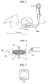
- FIG 1 is a side view showing a device 1 attached to the distal end of an endoscope S.
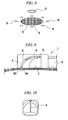
- FIG. 2 is a cross-sectional view taken along the line X-X in FIG 1
- FIG 3 is a cross-sectional view taken along the line Y-Y in FIG 1 .
- the device 1 includes: a cap 2 fitting onto the distal end of the endoscope S; and a slide block 3 attached to the distal end of the endoscope S and being capable of moving in the axial line direction of the endoscope S.
- the cap 2 is formed to have a ring shape.
- the cap 2 is made of a transparent material in an attempt not to disturb the visual field of the endoscope S, and the lower end of the cap 2 projects distally and has an arch shape in side view.
- the slide block 3 includes: a freely movable proximal end section 4 fitting onto the distal end of the endoscope S; and a forward expansion section 5 expanding distally from the upper end of the proximal end section 4.
- the slide block 3 is also made of a transparent material in an attempt not to disturb the visual field of the endoscope S.
- the slide block 3 is operated by an operation wire, not shown in the drawings, to slide in a longitudinal direction of the endoscope S.
- the operation wire it is preferable that the operation wire have a latchet mechanism that can hold the slide block 3 at an arbitrary position.
- a space formed between the forward expansion section 5 of the slide block 3 and the cap 2 is a living-tissue-introducing section 6.
- An instrument holder 7 is provided in an upper section of the proximal end section 4.
- a so-called externally-installable lift instrument 8 is inserted through the instrument holder 7.
- the lift instrument 8 is capable of moving along the axial line so that the lift instrument 8 passes in the exterior of an endoscope S but not inserted through the channel of the endoscope S.
- An example of the lift instrument 8 shown here is a grasping forceps.
- the hollow forward expansion section 5 has a rectangular cross section having a bottom surface section 5a formed in the lower part thereof and having an arch concave shape banding along the outer shape of the cap 2.
- a guide section 9 which is a guide groove or a guide rail is provided on the bottom surface of the bottom surface section 5a.
- a mating guide section 8c attached to the distal end of the instrument 8 engages with the guide section 9.
- the instrument 8 being extended or retracted is guided along the guide section 9.
- a through-hole 10 is formed on the bottom surface section 5a. The distal end of a T-bar suture instrument 11 inserted through a channel of the endoscope S can penetrate the through-hole 10 as shown in FIG. 4 .
- an insertion section of the endoscope S is inserted from a natural orifice, for example, the mouth into a lumen, for example, a stomach; the stomach or the like is insufflated so that the lumen is in an inflated state; and then, the distal end of the endoscope S is moved towards the vicinity of the object site, that is, the diseased tissue X.
- a natural orifice subject to the insertion of the endoscope S is not necessarily the mouth.
- the nasal cavity or anus may be used alternatively.
- the endoscope S may be inserted directly from a natural orifice into the lumen without using an overtube 200 in contrast to an example shown in the drawing using the overtube 200 for inserting the endoscope S.
- the diseased tissue X is specified based on an image obtained with an observation section provided at the distal end of the endoscope S. As shown in FIG 6 , upon specifying the diseased tissue X, markings are provided to clarify the position of the diseased tissue X. Adoptable examples of providing markings are spraying a colorant, providing markings around the diseased tissue X with a high-frequency device, and attaching marking members such as clips.
- the distal end of a tube is located in the vicinity of the diseased tissue X by using, for example, an operation channel of the endoscope S, and a colorant harmless to the human body, for example, methylene blue, indigo carmine, or triazine blue is spread from the opening of the distal end.
- a colorant harmless to the human body for example, methylene blue, indigo carmine, or triazine blue is spread from the opening of the distal end.
- iodine may be sprayed in place of spreading a colorant.
- the distal end of the marking device is located in the vicinity of the diseased tissue X by using the operation channel of the endoscope S, and markings are provided to predetermined positions while observing the positions with the observation section of the endoscope S (reference symbol B in FIG 6 indicates a section where a marking is provided).
- a usable marking device is a heating element such as a high-frequency knife, a high-frequency forceps, a high-frequency snare, and a heat probe, or an ultrasonic device.
- the distal end of a clip-retaining device is located in the vicinity of the diseased tissue X by using the operation channel of the endoscope S, and clips are attached to predetermined positions around the diseased tissue X while observing the positions with the observation section of the endoscope S.
- the living tissue in the vicinity of the diseased tissue X is lifted by using the device 1 shown in the previously explained FIGS. 1 to 4 .
- the device 1 may be installed to the endoscope S initially so that the device 1 is inserted into the body cavity together with the endoscope S unitarily.
- the endoscope including a marking instrument upon conducting the observation and providing markings may be retracted from the overtube 200 temporarily, and the endoscope having the initially-installed device 1 may be inserted into the lumen.
- Markings are provided around the site which is subject to be lifted before lifting the living tissue (see reference symbol C in FIG. 6 ).
- the points having the markings are lifted, and the diseased tissue itself is not grasped directly and lifted.
- an example of providing markings is to provide markings onto the living tissue with a high-frequency device or the like or to attach marking members such as clips.
- the markings may be provided simultaneously or separately with respect to the markings provided for clarifying the position of the diseased tissue X.
- the mucosa corresponding to the site C is removed or incised with a device 12 for incision use, and a muscle coat D thereinside is exposed in advance (see FIG 8 ).
- the muscle coat D is thus exposed prior to lift because it is difficult to lift a full thickness of a site including a mucosa, a submucosa, a muscle coat, and a serosa when a grasping forceps grasps a mucosa.
- a device for incision to expose the muscle coat D is a heating element such as a high-frequency knife, a high-frequency forceps, a high-frequency snare, and a heat probe, or an ultrasonic device. Alternatively, a scissors forceps or the like may be used.
- the lift instrument 8 of the device 1 is positioned above a site subject to lift in which the muscle coat D is exposed. Subsequently, the lower part of the cap 2 of the device 1 and the lower part of the slide block 3 are directed toward the living tissue respectively and compressed downward as shown in FIG 9 .
- the lift instrument 8 is extended in this state.
- the lift instrument 8 extends along the guide section 9 provided on the bottom surface of a bottom section 5a of the forward expansion section 5 and is finally disposed to be opposed to the muscle coat D in the site subject to lift.
- a pair of jaw sections 8a and 8b are opened by a proximal operation of an instrument and compressed downward in this state, and then the jaw sections 8a and 8b are closed (see FIG 11 ).
- the muscle coat or a living tissue disposed underneath is grasped with the pair of jaw sections 8a and 8b. It should be noted that the incision of mucosa may be omitted based on the length of organ or a configuration associated with a grasping instrument.
- the air in the lumen a stomach or the like, is purged to provide slack to the lumen.
- Slack is provided to the lumen in this manner for facilitating a lifting of the living tissue.
- the air purged from the lumen is in a state that does not disturb the observation with the endoscope and the lifting operation
- the lift instrument 8 is drawn proximally upon providing slack to the lumen while the muscle coat D is grasped with the pair of jaw sections 8a and 8b.
- the pair of jaw sections 8a and 8b are retracted while grasping the muscle coat D or the like and being guided along the guide section 9. That is, in the beginning, the a pair of jaw sections 8a and 8b are lifted substantially orthogonally with respect to the surface of the living tissue, and then the pair of jaw sections 8a and 8b are moved proximally relative to the endoscope S so that the pair of jaw sections 8a and 8b are substantially parallel to the surface of the living tissue.
- the living tissue in a folded state drawn by moving the pair of jaw sections 8a and 8b is retracted into the living-tissue-introducing section 6.
- the forward expansion section 5 is drawn proximally to the endoscope S by operating an operation wire, not shown in the drawing. This results in shortening the distance between the forward expansion section 5 and the cap 2, thereby allowing a distally-located living tissue in a lifted state to make close contact with a proximally-located living tissue in a lifted state.
- the device 1 has two functions including: a function of compressing the living tissue downward with the lower part of the forward expansion section 5 and the lower part of the cap 2 so that a wide range of the living tissue subject to lift is not raised unitarily; and a function of drawing the distally-located living tissue proximally and overlaying the distally-located living tissue with the proximally-located living tissue making close contact therewith so that a suture operation, which will be explained later, can be facilitated after the lifting operation.
- a suturing means is inserted into the lumen, and the serosas of the living tissue lifted with the inserted suturing means are contacted closely and fixed.
- the T-bar suture instrument 11 As the suturing means, the T-bar suture instrument 11 having the T-bar 11a pre-installed as shown in FIG. 13 is disposed to be opposed to the lifted living tissue by using the operation channel of the endoscope S.
- a puncture needle 13 is extended to penetrate the distally-located living tissue, the proximally-located living tissue, and the through-hole 10 of the bottom section 5a. Subsequently, the T-bar 11a is extended from the distal end of the puncture needle 13 and retained.
- the puncture needle 13 is removed from the living tissue, and the distally-located living tissue and the proximally-located living tissue are placed between a fastener 11c and the T-bar 11a and fixed there by pulling a thread 11b. It is preferable that the endoscope S in this state be directed upward. This is to prevent the puncture needle 13 from damaging ambient organs when the puncture needle 13 is projected from the operation channel of the endoscope S. Alternatively, damage to ambient organs can be prevented in another configuration capable of limiting a projection degree of the puncture needle 13 with a stopper or the like, not shown in the drawing, for preventing the puncture needle 13 from projecting from the distal end of the forward expansion section 5.
- the suturing means in place of the T-bar suture instrument 11 is a stapler, a thread, a clip, a resilient coil or the like.
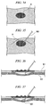
- the living tissues including the diseased tissue X are overlaid in two forms: in one form, the living tissues are bent along a line Za trespassing the diseased tissue X as shown in FIGS. 14A and 14B ; and in another form, the living tissues are bent along a line Zb not trespassing the diseased tissue X so that the diseased tissue X comes to one side with respect to the line Zb.
- the two pieces of living tissue including the diseased tissue X in an overlaid state are sutured at plural lifted basal points.
- Reference symbols H indicate the sutured points as shown in FIGS. 14B and 15B . As shown in FIG 4 , accretion of the closely-contacting serosas occurring over time in the sutured points results in joining the two pieces of living tissue unitarily.
- the lumen, stomach or the like is insufflated to obtain a visual field for the endoscope S.
- the diseased tissue X is resected from the fixed living tissue by resecting the full thickness of tissues between the diseased tissue X and the sutured sections.
- Reference symbol D indicates the point subject to resection as shown in FIGS. 14B, 15B , and 16 .
- the device which is inserted into the operation channel of the endoscope S for resecting the living tissue in this case is a high-frequency device such as a high-frequency knife, a high-frequency forceps, and a high-frequency snare or the like, or an ultrasonic device.
- a scissors forceps may be used for incision.
- a stapler may be used for incision.
- the living tissue grasped and lifted at predetermined points may be resected while applying tension thereto with a grasping forceps in an attempt to keep trapping the living tissue.
- the aforementioned resection method can prevent contamination in the abdominal cavity because the section subject to resection is sutured in advance, and gastric content or air is prevented from leaking from the resected sections into the abdominal cavity.
- the configuration in which the lifting and the suturing of the tissue are repeated, and the diseased tissue is surrounded by the sutured section instead of retracting the living tissue into a limited housing space or the like and resecting the tissue does not limit the ranges of the suturing points and subsequently-resecting points, thereby allowing a large area of resection.
- resected ends may be further closed with clips or the like for obtaining more reliable sealing capability at the resected sections.
- hemostatic treatment is conducted by using, for example, a high-frequency device such as a high-frequency knife, a high-frequency forceps, and a high-frequency snare or the like or a heating element such as a heat probe or the like.
- a high-frequency device such as a high-frequency knife, a high-frequency forceps, and a high-frequency snare or the like or a heating element such as a heat probe or the like.
- astriction may be conducted by retaining clips, snares, or rubber members or the like.
- chemical hemostatic treatment may be conducted by, for example, injecting or spreading chemicals.
- a leak test as to whether the resected section is fully closed may be conducted by, for example, insufflating the lumen and examining the change in pressure after a predetermined time. Granted that a leak is detected, the opening section may be sutured more densely by the aforementioned suturing means.
- the resected section may be closed with a device such as a clip, a snare, or a rubber member for preventing the resected section from reopening after the surgery.
- a device such as a clip, a snare, or a rubber member for preventing the resected section from reopening after the surgery.
- the resected living tissue including the diseased tissue is collected with an instrument for collection as shown in FIG 17 .
- a usable instrument for collection is a grasping forceps, a tripod forceps, a basket forceps, or a snare or the like.
- the diseased tissue may be collected by means of suctioning using a channel of an endoscope for suction or a tube such as an overtube or the like.
- the diseased tissue may be collected with a net member such as a tissue-collection net.
- FIGS. 18 to 21 show a modified example of the device for endoscopically lifting the living tissue in the vicinity of the diseased tissue X.
- a device 20 shown here has a cap 21 attached to the endoscope S, and has a lift instrument 22 of an externally-attachable type disposed along the axial line and being capable of moving therealong.
- the lift instrument 22 has an outer tube 23 having a coil sheath 24 inserted therethrough and being capable of extending or retracting.
- a grasping section 22a is attached to the distal end of the coil sheath 24.
- the coil sheath 24 has a pre-curve.
- the grasping section 22a of the distal end is substantially orthogonal to and opposed against the living tissue disposed underneath.
- the muscle coat that has been subjected to removal of mucosa in advance and exposed externally can be grasped with the grasping section 22a, the living tissue including the diseased tissue can be lifted by drawing the muscle coat in this state together with the coil sheath 24 proximally relative to the endoscope S.
- an instrument for lifting and grasping the living tissue is a forceps 26 having an arrowhead shape as shown in FIG. 22A , a forceps 27 having a spiral-letter shape as shown in FIG 22B , a forceps 28 having a distal end having a bending hook shape as shown in FIG. 22C , or an anchor 29 having a T-bar 29b attached to the distal end of a thread 29a as shown in FIG. 22D .
- FIGS. 23 to 25 show another modified example of the device for endoscopically lifting the living tissue in the vicinity of the diseased tissue X.
- a device 30 in this modified example is different from that shown in the aforementioned modified example 1 because of having a grasping mechanism 32 provided at a lower section of the distal end of a cap 31 attached to the distal end of the endoscope S. That is, a pair of jaw sections 32a and 32a attached to the distal end of the cap 31 and capable of grasping a living tissue are opened or closed by an extending or a retracting operation to an operation wire, not shown in the drawing, extending proximally through, for example, the channel of an endoscope.
- a cap tip end section 33 is capable of moving in the axial line direction relative to a cap main body.
- the position of the cap tip end section 33 relative to the cap main body is determined by operating an operation section such as a wire or the like , which is not shown in the drawing.
- the device 30, upon determining the site of the living tissue subject to being lifted, grasps the living tissue with the pair of jaw sections 32a and 32a attached to the distal end of the cap 31 and sets the position of the distal end of the endoscope S. Simultaneously, the angle of the distal end of the endoscope S with respect to the living tissue is set as shown in FIG. 24 , and after that, the externally-attachable lift instrument 22 is extended. Subsequently, the muscle coat having previously undergone removal of mucosa from the surface thereof to be exposed externally is grasped with the grasping section 22a of the distal end. After that, the attitude of the endoscope S is adjusted so that the endoscope S is in parallel with the surface of the living tissue as shown in FIG.
- the grasped living tissue can be lifted by drawing the grasped living tissue proximally together with the coil sheath 24.
- the cap tip end section 33 is operated and extended if necessary as shown in FIG. 25B . This results in causing the distally-located living tissue to make close contact with the proximally-located living tissue. Therefore, the following suturing process is facilitated.
- the device 30 in this case capable of determining the positional relationship between the suturing section and the grasping section strictly by grasping the living tissue with the grasping mechanism 32 attached to the distal end of the cap 31.
- a lifting instrument usable in this case may not have a pre-curve.
- FIG 26 shows another modified example of the device for endoscopically lifting the living tissue in the vicinity of the diseased tissue X.
- a device 40 shown in FIG. 26 has a cap 41 having a needle 42 attached to the distal end thereof. According to the device 40, the position of the cap 41 relative to the living tissue and the position of the distal end of the endoscope S having the cap 41 attached thereto relative to the living tissue can be determined by inserting the needle 42 of the distal end of the cap 41 into the living tissue.
- FIGS. 27 and 28 show another modified example of the device for endoscopically lifting the living tissue in the vicinity of the diseased tissue X.
- a device 50 shown here has two externally-attachable and freely-extendable-and-retractable lift instruments 52 attached above a cap 51 and aligned laterally while placing the cap 51 therebetween.
- the present invention is not limited to the configuration attaching two pieces of lift instruments 52; that is, three or more pieces of the lift instruments 52 may be attached; and alternatively, one piece of the lift instrument 52 may be attached as long as the width of the treatment section thereof is designed to be several times as wide as that of an ordinary treatment instrument.
- the living tissue lifted by using the device 50 having the aforementioned configuration and sutured by projecting the suture means from the operation channel of the endoscope S is further compressed by the lower end of the cap 51 and grasped with the laterally-aligned lift instruments 52; therefore, the living tissue is supported at three points and lifted. Therefore, the surface of the living tissue subject to suture can be defined accurately in a suturing process.
- FIGS. 29 and 30 show another modified example of the device for endoscopically lifting the living tissue in the vicinity of the diseased tissue X.
- a device 60 shown here is provided with: an externally-attachable lift instrument 61; a first overtube 62 for accommodating the endoscope S; and a second overtube 63 disposed in the exterior of the first overtube 62 and being capable of moving along the axial line.
- Two holes 64 and 65 aligned in the axial line direction are formed on the distal end of the first overtube 62.
- the lift instrument 61 penetrates the proximally-located hole 64 from the inside and penetrates the distally-located hole 65 inwardly from the outside.
- the distal end of the lift instrument 61 projects outward from the opening of the distal end of the first overtube 62.
- the second overtube 63 in a normal state is retracted relative to the distal end so that the distal end of the second overtube 63 does not overlap the holes 64 and 65 of the first overtube 62.
- the second overtube 63 is extended as shown in FIG 30 and the lift instrument 61 penetrating the proximally-disposed hole 64 and projecting outward is compressed by the distal end of the second overtube 63 from the proximal end to the distal end in the axial direction.
- the curvatures of the sections of the lift instrument 61 compressed by the second overtube 63 penetrating the holes 64 and 65 increase respectively, and the inclination angle increases to some degree relative to the living tissue underneath. Subsequently, it is possible to grasp the living tissue easily by extending the lift instrument 61 which maintains this state, that is, while a certain degree of significant inclination angle is maintained relative to the living tissue.
- FIG 31 shows another modified example of the device for endoscopically lifting the living tissue in the vicinity of the diseased tissue X.
- a device 70 shown here has: an externally-attachable lift instrument 71; and a tube-lock instrument 72 passing through the operation channel of the endoscope S and projecting distally.
- the tube-lock instrument 72 is capable of extending or retracting and locks an outer tube 71a of the instrument 71.
- the device 70 can adjust the angle of the distal end of the instrument 71 with respect to the living tissue since the outer tube 71 a of an instrument is locked with a locking section 72a of the distal end of the tube-lock instrument 72, and the tube-lock instrument 72 is operated to extend or retract via the operation channel. Accordingly, the living tissue can be grasped with the instrument 71 easily by setting the angle of the distal end of the instrument 71 with respect to the living tissue corresponding to the condition of the living tissue.
- FIGS. 32 and 33 show another modified example of the device for endoscopically lifting the living tissue in the vicinity of the diseased tissue X.
- a device 80 shown here has a forceps 82 having needles which are attached to the distal end of a coil sheath 81.
- the forceps 82 having needles 82a at the distal ends thereof can be opened and closed with an operation wire which is not shown in the drawing. It is preferable that the length of each needle be set to be more significant than the thickness of the mucosa of the living tissue and not to project on the opposite side.
- the needles 82a penetrate the living tissue since the forceps 82 having the needles 82a in a substantially 180 degree opened state are disposed to be opposed to the living tissue subject to lift and extended.
- the needles 82a penetrate the mucosa of the living tissue and are inserted into the muscle coat.
- the full thickness of the living tissues can be grasped reliably without resecting the mucosa since the muscle coat can be grasped with the needles.
- an operation to retract the coil sheath 81 by operating the wire, not shown in the drawing causes the forceps 82 having the needles to be closed, thereby allowing the living tissue to be grasped. And then, the living tissue in the grasped state can be lifted by drawing the forceps 82 having the needles proximally.
- FIGS. 34 to 37 show another modified example of the device for endoscopically lifting the living tissue in the vicinity of the diseased tissue X.
- an injection needle 90 is passed through the operation channel of the endoscope; the injection needle 90 is inserted into a submucosa 91 in the vicinity of the diseased tissue X; normal saline solution is injected into the submucosa 91; and then, a muscle coat 92 is removed from the mucosa.
- the present invention is not limited to this case in which the muscle coat 92 is removed from the submucosa 91 by means of injection using the injection needle 90.
- the muscle coat 92 may be removed from the submucosa 91 by using another means, for example, an insufflation balloon.
- a guidewire is passed through the injection needle 90, and the distal end of the guidewire is retained in the muscle coat 92 which is subject to being lifted and is isolated from the submucosa 91 in advance.
- a hook 93 or a grasping forceps guided with the retained guidewire is fed into the muscle coat 92 and held there. Accordingly, the muscle coat in an arbitrary site of the living tissue can be lifted reliably with the locked hook 93 or the grasping forceps.
- FIGS. 38 to 39C show another modified example of the device for endoscopically lifting the living tissue in the vicinity of the diseased tissue X.
- a device 100 shown here has an outer sheath 101 having the endoscope S inserted therethrough and a channel 102 inserted through the outer sheath 101.
- a lift instrument 103 for example, a grasping forceps inserted through the channel 102 is capable of extending or retracting therethrough.
- the outer sheath 101 itself is extendable and retractable, and is rotatable around the axial line.
- the outer sheath 101 is operated to be rotated in advance, and the lift instrument 103 is disposed at a lower position close to the living tissue. Subsequently, a predetermined site of the living tissue is grasped with the lift instrument 103 while observing with the endoscope.
- the outer sheath 101 in this state as shown in FIG 39B is rotated, and then, the lift instrument 103 is positioned upward to be separated from the living tissue. Accordingly, the grasped site of the living tissue is lifted. Subsequently, as shown in FIG. 39C , the living tissue can be further lifted by drawing the lift instrument 103 together with the outer sheath 101 proximally.
- FIGS. 40 to 42 show another modified example of the device for proximally drawing an endoscopically-lifted living tissue in the vicinity of the diseased tissue X.
- a device 110 shown here has a cap 111 fitting onto the distal end of the endoscope S; and a magnet 112 attached to a lower end of the cap 111.
- An externally-attachable lift instrument 113 for example, a grasping forceps or the like capable of extending or retracting is attached to an upper section of the cap 111.
- the device 110 is provided with a cap 111; a magnet 112 attached to the lower end of the cap 111; and a magnet 114 used together with the magnet 112 for fixing the living tissue.
- the magnet 114 for fixing the living tissue is fixed onto the diseased tissue or the living tissue therearound in advance with a clip 115 or with other retaining instruments.
- the predetermined site of the living tissue is grasped with the lift instrument 113 while observing with the endoscope S, and then, this state of the lift instrument 113 is drawn proximally.
- the living tissue is supposed to be lifted, and this state of magnet 114 for fixing the living tissue fixed to the predetermined site of the living tissue approaches the magnet 112 of the lower end of the cap 111 in advance; thus, the magnet 114 is attracted by the magnet 112.
- the living tissue which is located distally relative to the distal end of the cap is drawn proximally in accordance with the movement of this state of the magnet 114 for fixing the living tissue.
- magnet 112 and the magnet 114 are illustrated as members attracting each other by a magnetic force in this modified example, this configuration is not restrictive and a configuration in which a magnetic substance is disposed to any one of the cap 111 and the device 110 and a magnetized member is disposed to the other thereof may be employed. This case also can exhibit the same effect as that of this modified example.
- FIGS. 43 to 46 show another modified example of the device for drawing the endoscopically-lifted living tissue in the vicinity of the diseased tissue X proximally relative to the cap.
- a device 120 shown here has a cap 121 fitting onto the distal end of the endoscope S; and an externally-attachable lift instrument 122, for example, a grasping forceps being capable of extending or retracting and attached on the cap 121.
- an externally-attachable snare 123 is attached on the bottom section of the cap 121.
- a predetermined length of metal bar 123a having high stiffness is assembled into the snare 123.
- the snare 123 is expanded in advance, and the predetermined site of the living tissue is grasped and lifted with the lift instrument 122 passing through the device 120 to draw the living tissue further proximally. Subsequently, the snare 123 is constricted into a linear state by using the metal bar 123a as shown in FIG. 45 . Constricting this state of snare 123 causes the living tissue distally located relative to the cap 121 to be drawn proximally, thereby causing the distally-located living tissue to make close contact with the proximally-located living tissue.
- a needle-like locking section 123aa serving as a stopper for the living tissue may be attached to the metal bar 123a (see FIG 44 ).
- FIG 47 shows another modified example of the device for drawing the endoscopically-lifted living tissue in the vicinity of the diseased tissue X proximally relative to the cap.
- a cap 131 fitting onto the distal end of the endoscope S has two elements. That is, one is a cap main unit 132 fitting onto the distal end section of the endoscope S; and the other one is a cap tip end section 133 capable of moving in the axial line direction (the axial line direction of the endoscope) relative to the cap main unit 132.
- An externally-attachable lift instrument 134 capable of extending or retracting, for example, a grasping forceps or the like is attached above the cap 132.
- the cap tip end section 133 is operated to move by means of an operation wire, or an operation means such as an air cylinder or the like.
- the predetermined site of the living tissue is grasped with the lift instrument 134 while observing with the endoscope, and then, this state of the lift instrument 134 is drawn proximally.
- the proximally-located living tissue can be compressed to the distally-located living tissue by sliding the cap tip end section 133 further distally with an operation means not shown in the drawing. This results in drawing the distally-located living tissue toward the proximally-located living tissue, thereby allowing the distally-located living tissue to make close contact with the proximally-located living tissue.
- FIGS. 48 and 49 show another modified example of the device for drawing the endoscopically-lifted living tissue in the vicinity of the diseased tissue X proximally relative to the cap.
- a device 140 shown here has a cap 141 fitting onto the distal end of the endoscope S; and a living-tissue-retainer 142 attached in a lower part of the cap 141 through which a puncture needle 144 of the suturing means can be inserted.
- the living-tissue-retainer 142 is capable of moving in the axial line direction of the endoscope S.
- An externally-attachable lift instrument 143 for example, a grasping forceps or the like capable of extending or retracting is attached above the cap 141.
- the predetermined site of the living tissue is grasped with the lift instrument 143 while observing with the endoscope S, and then, this state of the lift instrument 143 is drawn proximally.
- the distally-located living tissue and the proximally-located living tissue are penetrated with the puncture needle 144 of the suturing means projecting distally from the operation channel of the endoscope.
- the proximally-located living tissue can be compressed to the distally-located living tissue by moving the living-tissue-retainer 142 distally while the living tissue is penetrated with the puncture needle 144.
- FIGS. 50 to 51B show another modified example of the device for compressing downward the endoscopically-lifted living tissue in the vicinity of the diseased tissue X.
- a device 150 shown here has a cap 151 fitting onto the distal end of the endoscope S; and an externally-attachable lift instrument 152, for example, a grasping forceps being capable of extending or retracting and attached on the cap 151.
- an arm 153 having an L-letter shape in side view is attached on an upper section of the cap 151.
- the arm 153 is capable of pivoting around the axial line orthogonal to the axial line of the cap 151.
- the pivoting operation to the arm 153 is provided by means of a wire not shown in the drawing, an air cylinder, or a coil spring or the like.
- the arm 153 is pivoted proximally as shown in FIG. 51A , and the predetermined site of the living tissue is grasped with the lift instrument 152 while observing with the endoscope S, and then, this state of the lift instrument 152 is drawn proximally. While or subsequent to drawing the lift instrument 152 proximally, the arm 153 is pivoted to be disposed distally with an operation means. Since the spring or the operation wire or the like applies a force to the arm 153 having undergone the pivoting operation to pivot the arm 153 in the same direction, the distally-located living tissue is compressed downward with the arm 153. This results in preventing the distally-located living tissue from being raised inadvertently and allowing the distally-located living tissue to make close contact with the proximally-located living tissue.
- FIGS. 52 to 56 show another modified example of the device for compressing downward the endoscopically-lifted living tissue in the vicinity of the diseased tissue X and drawing the living tissue proximally relative to the cap.
- a device 160 shown here has a cap 161 fitting onto the distal end of the endoscope S; and an externally-attachable lift instrument 162, for example, a grasping forceps being capable of extending or retracting and attached in an upper section of the cap 161.
- a distally-extending guide section 163 having a guide groove 163a disposed thereinside is provided in an upper section of the cap 161.
- the guide section 163 has a living-tissue-retainer member 164 having an L-letter shape in side view and being capable of moving in the axial line direction of the endoscope S by means of an upper plate section 164a guided with the guide groove 163a.
- the movement of the living-tissue-retainer member 164 is configured to be operated with a wire or an air cylinder or the like not shown in the drawings.
- a through-hole 164b capable of inserting the puncture needle of the T-bar suture instrument therethrough is formed on a front surface section of the living-tissue-retainer member 164.
- the living-tissue-retainer member 164 is disposed distally as shown in FIG 52 , and the predetermined site of the living tissue is grasped with the lift instrument 162 while observing with the endoscope S, and then, this state of the lift instrument 162 is drawn proximally as shown in FIG 54 . In an attempt not to raise the distally-located living tissue, the distally-located living tissue in this state is compressed downward with the lower part of the living-tissue-retainer member 164.
- the living-tissue-retainer member 164 is drawn proximally as shown in FIG 55 .
- this allows the distally-located living tissue to be drawn proximally, thereby resulting in allowing the distally-located living tissue to make close contact with the proximally-located living tissue.
- distal end of the cap fitting onto the distal end of the endoscope may have an inclined shape as shown in FIGS. 52 to 55 , or a flatly-cut shape as shown in FIG. 56 .
- FIG 57 shows another modified example of the device for compressing downward the endoscopically-lifted living tissue in the vicinity of the diseased tissue X and drawing the living tissue proximally relative to the cap.
- a device 170 shown here has a living-tissue-retainer member 171 having a distal end section 171a capable of rotating around an axial line 171b.
- the rotation of the distal end section 171 a is configured to be operated with a wire or an air cylinder or the like not shown in the drawing. It should be noted that other sections that are the same as those of the previously-explained configurations are assigned the same reference symbols.
- the living tissue when being lifted can be compressed downward with the upright distal end section 171 a of the living-tissue-retainer member 171.
- the distally-located living tissue can be drawn proximally by fully drawing the living-tissue-retainer member 164 or drawing the distal end section 171a of the living-tissue-retainer member 171 in a deeper angle proximally.
- FIGS. 58 and 59 show another modified example of the device for compressing downward the endoscopically-lifted living tissue in the vicinity of the diseased tissue X and drawing the living tissue proximally relative to the cap.
- a device 180 shown here has a cap 181 fitting onto the distal end of the endoscope S; and an externally-attachable lift instrument 182, for example, a grasping forceps being capable of extending or retracting and attached in an upper section of the cap 181.
- a plate member 183 made of a flexible material and having a pre-curve is attached above the cap 181. The movement of the plate member 183 is configured to be operated with a wire or an air cylinder or the like not shown in the drawing.
- the plate member 183 is extended in advance as shown in FIG. 59 . And then, the distal end of the plate member 183 bends downward by the flexible property of itself.
- the plate member 183 is extended distally in this manner, and the predetermined site of the living tissue is grasped with the lift instrument 182 while observing with the endoscope S, and then, this state of the lift instrument 182 is drawn proximally.
- the distally-located living tissue in this state is compressed downward with the distal end of the plate member 183.
- the distally-located living tissue can be drawn proximally by lifting the living tissue and then drawing the plate member 183 proximally. This results in allowing the distally-located living tissue to make close contact with the proximally-located living tissue.
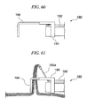
- FIGS. 60 and 61 show another modified example of the device for compressing downward the endoscopically-lifted living tissue in the vicinity of the diseased tissue X and drawing the living tissue proximally relative to the cap.
- a device 190 shown here is different from that shown in FIGS. 52 to 56 because a freely extendable or retractable distal end section 192a like a grasping forceps or the like of an externally-attachable lift instrument 192 attached above the cap 161 is capable of pivoting upward via a link 193.
- the pivoting angle of the distal end section 192a is configured to be operated with a wire or an air cylinder or the like not shown in the drawing. It should be noted that other sections that are the same as those of the previously-explained configurations shown in FIGS. 52 to 56 are assigned the same reference symbols.
- the living-tissue-retainer member 164 having an L-letter shape in a side view can compress the distally-located living tissue downward in an attempt not to raise the distally-located living tissue and draw the distally-located living tissue distally.
- the device 190 can lift the living tissue significantly since the distal end section 192a of the lift instrument 192 can be lifted significantly; therefore, it is not necessary to draw the lift instrument 192 proximally.
- FIG 62 is an isometric view showing another modified example of the device 150 shown in FIG 50 .
- a device 150a in this modified example has an arm 153a instead of the arm 153.
- the arm 153a is rotatably connected to two points separated from each other in the cap 151. Concretely, the arm 153a is fitted in and connected to support grooves formed in two points opposing to each other in a radial direction.
- FIGS. 63A and 63B show an operation upon using the device 150a.
- the arm 153a can be pivoted to be disposed distally with an operation means similar to the arm 153.
- the living tissue located more distally than the device 150a is compressed downward with the arm 153a. This results in preventing the distally-located living tissue from being raised.
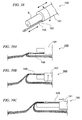
- FIGS. 64 to 66 show another modified example of the device 160 shown in FIGS. 52 to 56 .
- a device 160a has a cap 161a configured to have substantially the same shape and the same size as those of the device 160.
- the cap 161a is fitted so as to move in an axial direction relative to the endoscope S.
- FIG 65 shows an operation upon using the device 160a.
- the cap 161 a is linearly operated in an axial direction of the endoscope with respect to the endoscope S after the living tissue is lifted. Then, the living-tissue-retainer member 164 and the cap 161a approach each other, and the living tissue is pinched by the living-tissue-retainer member 164 and the cap 161a. In this manner, similar to the device 160 shown in the modified example 15 described above, the distally-located living tissue is allowed to be drawn proximally, thereby allowing the distally-located living tissue to make close contact with the proximally-located living tissue in this modified example.
- distal end of the cap may have a flatly-cut shape as shown in FIG. 66 also in this modified example.
Abstract
Description
- The present invention relates to a suture instrument for an endoscope.
- Conventional endoscopic mucosal resection for treating a diseased tissue, for example, cancer developed in a digestive canal without carrying out an abdominal operation has been commonly in practice in which a mucosa deteriorated by a diseased tissue is resected with an instrument for an endoscope inserted into a body cavity from the mouth or an anus.
- In particular, en bloc resection, i.e., full thickness resection including a mucosa, a submucosa, a muscle coat, and a serosa has been considered in recent years for resecting the diseased tissue reliably and facilitating histopathological diagnosis of the resected diseased tissue.
- An example of the full thickness resection conducted on a section including a diseased tissue in a hollow organ, for example, a stomach or a colon disclosed in the specification of
U.S. Patent No. 7,334,718 is a surgical method in which a cylindrical housing is attached to the distal end of an endoscope; a living tissue is retracted into the housing by using a grasping forceps; the living tissue is resected in the vicinity of the opening of the housing by using rotational blades; and a distal end section of the living tissue relative to the resected point is sutured with a stapler. - Also, another example of a full thickness resection conducted on a section including a diseased tissue in a hollow organ disclosed in the specification of
U.S. Patent No. 7,326,221 is a surgical method in which a cylindrical housing is attached to the distal end of an endoscope; a living tissue is retracted into the housing by means of suctioning; the suctioned living tissue is tailored using a T-bar suture instrument; and the living tissue is resected in this state. - However, in the surgical methods described in
U.S. Patent Nos. 7,334,718 and7,326,221 , the scope of resection is limited since these surgical methods suction the living tissue into the housing and then resect the living tissue; therefore, full-thickness resection is difficult in the case of a widely spreading diseased tissue. - The present invention is made in consideration of the above-described circumstances, and has an object to provide a suture instrument for an endoscope which can lift a diseased tissue in a wide range for performing en bloc resection of the diseased tissue in full thickness.
- In order to achieve the above object, the present invention proposes the following means.
- According to the present invention, a suture instrument for an endoscope which is attachable to an endoscope that is able to be inserted into a body cavity from a distal side, includes: an attachment for an endoscope including a forceps that grasps a living tissue located at a predetermined grasping position to lift the living tissue in a thickness direction of the living tissue, and a holding section that pinches the living tissue lifted by the forceps; and a suture device that sutures the living tissue pinched in the attachment for an endoscope, wherein the holding section includes a living-tissue-contact section that extends and retracts or pivots in a direction intersecting the living tissue lifted by the forceps to be contacted with the living tissue.
- Also, it is preferable that the forceps extend and retract along a predetermined track in a direction intersecting a surface of the living tissue and in a proximal end direction in the endoscope from the grasping position.
- Also, the forceps may move linearly in a direction normal to a surface of the living tissue from the grasping position.
- Also, it is preferable that the holding section include a main body provided in a fixed positional relationship relative to the endoscope, and an extending/retracting mechanism that extends and retracts the living-tissue-contact section with respect to the main body.
- Also, the holding section may include a main body provided in a fixed positional relationship relative to the endoscope, and a pivoting mechanism that pivots the living-tissue-contact section around a predetermined pivot axis with respect to the main body.
- Also, it is preferable that the living-tissue-contact section have a flexible property.
- Furthermore, it is preferable that the holding section include a main body provided in a fixed positional relationship relative to the endoscope, and an extending/retracting mechanism that extends and retracts the living-tissue-contact section with respect to the main body, and the extending/retracting mechanism extends and retracts the living-tissue-contact section with respect to the main body between a first position where the living-tissue-contact section is retracted to the outside of a visual field of the endoscope at a part of an outer surface of the main body and a second position where the living-tissue-contact section is positioned within the visual field of the endoscope and contacts the living tissue lifted by the forceps through the flexible property of itself.
- Also, it is preferable that the attachment for an endoscope include a guide section which is inclined with respect to an axial direction of the endoscope and guides the forceps to the grasping position.
- Note that in this specification, "inclination" does not exclude a curved shape, and may include a shape in which at least a part of a trace along which the forceps extends and retracts in a track along which the guide section guides the forceps has an angle with respect to an axial direction of the endoscope.
- According to a suture instrument for an endoscope of the present invention, it is possible to lift a diseased tissue in a wide range for performing en bloc resection of the diseased tissue in full thickness.
-
-
FIG 1 is a side view of the distal end section of a device of a suture instrument for an endoscope according to a first embodiment of the present invention. -
FIG 2 is a cross sectional view of the aforementioned device taken along the line X-X. -
FIG 3 is a cross sectional view of the aforementioned device taken along the line Y-Y. -
FIG 4 is a side view of the distal end section of the aforementioned device in use. -
FIGS. 5 and 6 are isometric views for explaining a process of the endoscopic surgical operation method using the device according to an embodiment of the present invention. -
FIG 7 shows an image obtained through the endoscope for explaining a process of the endoscopic surgical operation method using the device according to an embodiment of the present invention. -
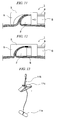
FIG 8 is an isometric view for explaining a process of the endoscopic surgical operation method using the device according to an embodiment of the present invention. -
FIG 9 is a side view for explaining a process of the endoscopic surgical operation method using the device according to an embodiment of the present invention. -
FIG 10 shows an image obtained through the endoscope for explaining a process of the endoscopic surgical operation method using the device according to an embodiment of the present invention. -
FIGS. 11 and 12 are side views for explaining a process of the endoscopic surgical operation method using the device according to an embodiment of the present invention. -
FIG 13 is an isometric view showing an example of a suture instrument used in the endoscopic surgical operation method using the device according to an embodiment of the present invention. -
FIGS. 14A and 15A are plan views for explaining a process of the endoscopic surgical operation method using the device according to an embodiment of the present invention. -
FIGS. 14B and 15B are isometric views for explaining a process of the endoscopic surgical operation method using the device according to an embodiment of the present invention. -
FIGS. 16 and 17 are isometric views for explaining a process of the endoscopic surgical operation method using the device according to an embodiment of the present invention. -
FIGS. 18 to 21 are side views showing a modified example of the device. -
FIGS. 22A to 22D are side views showing an example of a grasping instrument used for carrying out the endoscopic surgical operation method using the device. -
FIGS. 23 to 25B are side views showing another modified example of the device. -
FIG 26 is a side view showing another modified example of the device. -
FIGS. 27 and 28 are isometric views showing another modified example of the device. -
FIGS. 29 and 30 are cross-sectional views showing another modified example of the device. -
FIG 31 is an isometric view showing another modified example of the device. -
FIGS. 32 and 33 are cross-sectional views showing another modified example of the device. -
FIGS. 34 to 37 show another example of the endoscopic surgical operation method using the device. -
FIG 38 shows another modified example of the device. -
FIGS. 39A to 39C show another modified example of the device for carrying out the endoscopic surgical operation method using the device. -
FIGS. 40 to 42 show another modified example of the device. -
FIGS. 43 to 46 show another modified example of the device. -
FIGS. 47 to 49 show another modified example of the device. -
FIG 50 shows another modified example of the device. -
FIGS. 51A and 51B show another modified example of the device for carrying out the endoscopic surgical operation method using the device. -
FIGS. 52 to 56 show another modified example of the device. -
FIG 57 shows another modified example of the device. -
FIGS. 58 and 59 show another modified example of the device. -
FIGS. 60 and 61 show another modified example of the device. -
FIG 62 shows another modified example of the device. -
FIGS. 63A and 63B show an operation upon using the device shown inFIG 62 . -
FIG 64 shows another modified example of the device. -
FIG 65 shows an operation upon using the device shown inFIG 64 . -
FIG 66 shows another modified example of the device. - Embodiments of the present invention will be explained. A device used for the surgical method will be explained prior to explanation of the endoscopic surgical operation method of the present invention.
FIG 1 is a side view showing adevice 1 attached to the distal end of an endoscope S.FIG. 2 is a cross-sectional view taken along the line X-X inFIG 1, and FIG 3 is a cross-sectional view taken along the line Y-Y inFIG 1 . - The
device 1 includes: acap 2 fitting onto the distal end of the endoscope S; and aslide block 3 attached to the distal end of the endoscope S and being capable of moving in the axial line direction of the endoscope S. Thecap 2 is formed to have a ring shape. In addition, thecap 2 is made of a transparent material in an attempt not to disturb the visual field of the endoscope S, and the lower end of thecap 2 projects distally and has an arch shape in side view. Theslide block 3 includes: a freely movableproximal end section 4 fitting onto the distal end of the endoscope S; and aforward expansion section 5 expanding distally from the upper end of theproximal end section 4. Theslide block 3 is also made of a transparent material in an attempt not to disturb the visual field of the endoscope S. - In addition, the
slide block 3 is operated by an operation wire, not shown in the drawings, to slide in a longitudinal direction of the endoscope S. In addition, it is preferable that the operation wire have a latchet mechanism that can hold theslide block 3 at an arbitrary position. In addition, a space formed between theforward expansion section 5 of theslide block 3 and thecap 2 is a living-tissue-introducingsection 6. Aninstrument holder 7 is provided in an upper section of theproximal end section 4. A so-called externally-installable lift instrument 8 is inserted through theinstrument holder 7. Thelift instrument 8 is capable of moving along the axial line so that thelift instrument 8 passes in the exterior of an endoscope S but not inserted through the channel of the endoscope S. An example of thelift instrument 8 shown here is a grasping forceps. - As shown in
FIG. 2 , the hollowforward expansion section 5 has a rectangular cross section having abottom surface section 5a formed in the lower part thereof and having an arch concave shape banding along the outer shape of thecap 2. Aguide section 9 which is a guide groove or a guide rail is provided on the bottom surface of thebottom surface section 5a. Amating guide section 8c attached to the distal end of theinstrument 8 engages with theguide section 9. Theinstrument 8 being extended or retracted is guided along theguide section 9. In addition, a through-hole 10 is formed on thebottom surface section 5a. The distal end of a T-bar suture instrument 11 inserted through a channel of the endoscope S can penetrate the through-hole 10 as shown inFIG. 4 . - Next, the endoscopic surgical operation method using the
device 1 will be explained. - As shown in
FIG 5 , an insertion section of the endoscope S is inserted from a natural orifice, for example, the mouth into a lumen, for example, a stomach; the stomach or the like is insufflated so that the lumen is in an inflated state; and then, the distal end of the endoscope S is moved towards the vicinity of the object site, that is, the diseased tissue X. It should be noted that a natural orifice subject to the insertion of the endoscope S is not necessarily the mouth. The nasal cavity or anus may be used alternatively. In another configuration, the endoscope S may be inserted directly from a natural orifice into the lumen without using anovertube 200 in contrast to an example shown in the drawing using theovertube 200 for inserting the endoscope S. - The diseased tissue X is specified based on an image obtained with an observation section provided at the distal end of the endoscope S. As shown in
FIG 6 , upon specifying the diseased tissue X, markings are provided to clarify the position of the diseased tissue X. Adoptable examples of providing markings are spraying a colorant, providing markings around the diseased tissue X with a high-frequency device, and attaching marking members such as clips. - In a case of spreading a colorant, the distal end of a tube is located in the vicinity of the diseased tissue X by using, for example, an operation channel of the endoscope S, and a colorant harmless to the human body, for example, methylene blue, indigo carmine, or triazine blue is spread from the opening of the distal end. Alternatively, iodine may be sprayed in place of spreading a colorant. In the case of providing markings around the diseased tissue X with a marking device, for example, a high-frequency device, the distal end of the marking device is located in the vicinity of the diseased tissue X by using the operation channel of the endoscope S, and markings are provided to predetermined positions while observing the positions with the observation section of the endoscope S (reference symbol B in
FIG 6 indicates a section where a marking is provided). A usable marking device is a heating element such as a high-frequency knife, a high-frequency forceps, a high-frequency snare, and a heat probe, or an ultrasonic device. In the case of attaching marking members such as clips or the like, the distal end of a clip-retaining device is located in the vicinity of the diseased tissue X by using the operation channel of the endoscope S, and clips are attached to predetermined positions around the diseased tissue X while observing the positions with the observation section of the endoscope S. - Subsequently, the living tissue in the vicinity of the diseased tissue X is lifted by using the
device 1 shown in the previously explainedFIGS. 1 to 4 . Thedevice 1 may be installed to the endoscope S initially so that thedevice 1 is inserted into the body cavity together with the endoscope S unitarily. Alternatively, the endoscope including a marking instrument upon conducting the observation and providing markings may be retracted from theovertube 200 temporarily, and the endoscope having the initially-installeddevice 1 may be inserted into the lumen. - Markings are provided around the site which is subject to be lifted before lifting the living tissue (see reference symbol C in
FIG. 6 ). The points having the markings are lifted, and the diseased tissue itself is not grasped directly and lifted. As previously explained, an example of providing markings is to provide markings onto the living tissue with a high-frequency device or the like or to attach marking members such as clips. The markings may be provided simultaneously or separately with respect to the markings provided for clarifying the position of the diseased tissue X. - Also, as shown in
FIG 7 , the mucosa corresponding to the site C is removed or incised with adevice 12 for incision use, and a muscle coat D thereinside is exposed in advance (seeFIG 8 ). The muscle coat D is thus exposed prior to lift because it is difficult to lift a full thickness of a site including a mucosa, a submucosa, a muscle coat, and a serosa when a grasping forceps grasps a mucosa. A device for incision to expose the muscle coat D is a heating element such as a high-frequency knife, a high-frequency forceps, a high-frequency snare, and a heat probe, or an ultrasonic device. Alternatively, a scissors forceps or the like may be used. - Next, the
lift instrument 8 of thedevice 1 is positioned above a site subject to lift in which the muscle coat D is exposed. Subsequently, the lower part of thecap 2 of thedevice 1 and the lower part of theslide block 3 are directed toward the living tissue respectively and compressed downward as shown inFIG 9 . Thelift instrument 8 is extended in this state. Thelift instrument 8 extends along theguide section 9 provided on the bottom surface of abottom section 5a of theforward expansion section 5 and is finally disposed to be opposed to the muscle coat D in the site subject to lift. Subsequently, a pair ofjaw sections jaw sections FIG 11 ). That is, the muscle coat or a living tissue disposed underneath is grasped with the pair ofjaw sections - And then, the air in the lumen, a stomach or the like, is purged to provide slack to the lumen. Slack is provided to the lumen in this manner for facilitating a lifting of the living tissue. The air purged from the lumen is in a state that does not disturb the observation with the endoscope and the lifting operation
- Next, the
lift instrument 8 is drawn proximally upon providing slack to the lumen while the muscle coat D is grasped with the pair ofjaw sections jaw sections guide section 9. That is, in the beginning, the a pair ofjaw sections jaw sections jaw sections jaw sections section 6. - Subsequently, as shown in
FIG 12 , theforward expansion section 5 is drawn proximally to the endoscope S by operating an operation wire, not shown in the drawing. This results in shortening the distance between theforward expansion section 5 and thecap 2, thereby allowing a distally-located living tissue in a lifted state to make close contact with a proximally-located living tissue in a lifted state. - That is, the
device 1 has two functions including: a function of compressing the living tissue downward with the lower part of theforward expansion section 5 and the lower part of thecap 2 so that a wide range of the living tissue subject to lift is not raised unitarily; and a function of drawing the distally-located living tissue proximally and overlaying the distally-located living tissue with the proximally-located living tissue making close contact therewith so that a suture operation, which will be explained later, can be facilitated after the lifting operation. - Next, a suturing means is inserted into the lumen, and the serosas of the living tissue lifted with the inserted suturing means are contacted closely and fixed.
- In the case of using, for example, the T-bar suture instrument 11 as the suturing means, the T-bar suture instrument 11 having the T-
bar 11a pre-installed as shown inFIG. 13 is disposed to be opposed to the lifted living tissue by using the operation channel of the endoscope S. In addition, as shown inFIG 4 , apuncture needle 13 is extended to penetrate the distally-located living tissue, the proximally-located living tissue, and the through-hole 10 of thebottom section 5a. Subsequently, the T-bar 11a is extended from the distal end of thepuncture needle 13 and retained. After that, thepuncture needle 13 is removed from the living tissue, and the distally-located living tissue and the proximally-located living tissue are placed between afastener 11c and the T-bar 11a and fixed there by pulling athread 11b. It is preferable that the endoscope S in this state be directed upward. This is to prevent thepuncture needle 13 from damaging ambient organs when thepuncture needle 13 is projected from the operation channel of the endoscope S. Alternatively, damage to ambient organs can be prevented in another configuration capable of limiting a projection degree of thepuncture needle 13 with a stopper or the like, not shown in the drawing, for preventing thepuncture needle 13 from projecting from the distal end of theforward expansion section 5. - The suturing means in place of the T-bar suture instrument 11 is a stapler, a thread, a clip, a resilient coil or the like.
- After that, plural basal points of the living tissues in an overlapping state including the diseased tissue X are sutured by repeating the aforementioned lift and suture of the living tissue.
- The living tissues including the diseased tissue X are overlaid in two forms: in one form, the living tissues are bent along a line Za trespassing the diseased tissue X as shown in
FIGS. 14A and 14B ; and in another form, the living tissues are bent along a line Zb not trespassing the diseased tissue X so that the diseased tissue X comes to one side with respect to the line Zb. In either case, the two pieces of living tissue including the diseased tissue X in an overlaid state are sutured at plural lifted basal points. Reference symbols H indicate the sutured points as shown inFIGS. 14B and 15B . As shown inFIG 4 , accretion of the closely-contacting serosas occurring over time in the sutured points results in joining the two pieces of living tissue unitarily. - Upon concluding a sequence of operations associated with lift and suture, the lumen, stomach or the like is insufflated to obtain a visual field for the endoscope S.
- The diseased tissue X is resected from the fixed living tissue by resecting the full thickness of tissues between the diseased tissue X and the sutured sections. Reference symbol D indicates the point subject to resection as shown in
FIGS. 14B, 15B , and16 . The device which is inserted into the operation channel of the endoscope S for resecting the living tissue in this case is a high-frequency device such as a high-frequency knife, a high-frequency forceps, and a high-frequency snare or the like, or an ultrasonic device. In addition, a scissors forceps may be used for incision. Furthermore, a stapler may be used for incision. Moreover, the living tissue grasped and lifted at predetermined points may be resected while applying tension thereto with a grasping forceps in an attempt to keep trapping the living tissue. - The aforementioned resection method can prevent contamination in the abdominal cavity because the section subject to resection is sutured in advance, and gastric content or air is prevented from leaking from the resected sections into the abdominal cavity. In addition, the configuration in which the lifting and the suturing of the tissue are repeated, and the diseased tissue is surrounded by the sutured section instead of retracting the living tissue into a limited housing space or the like and resecting the tissue does not limit the ranges of the suturing points and subsequently-resecting points, thereby allowing a large area of resection. In addition, resected ends may be further closed with clips or the like for obtaining more reliable sealing capability at the resected sections.
- In addition, in a case of observing bleeding from the resected site when dissection is conducted, hemostatic treatment is conducted by using, for example, a high-frequency device such as a high-frequency knife, a high-frequency forceps, and a high-frequency snare or the like or a heating element such as a heat probe or the like. Alternatively, astriction may be conducted by retaining clips, snares, or rubber members or the like. In addition, chemical hemostatic treatment may be conducted by, for example, injecting or spreading chemicals.
- Subsequently, a leak test as to whether the resected section is fully closed may be conducted by, for example, insufflating the lumen and examining the change in pressure after a predetermined time. Granted that a leak is detected, the opening section may be sutured more densely by the aforementioned suturing means.
- In addition, the resected section may be closed with a device such as a clip, a snare, or a rubber member for preventing the resected section from reopening after the surgery.
- After the resection in the aforementioned manner, the resected living tissue including the diseased tissue is collected with an instrument for collection as shown in
FIG 17 . A usable instrument for collection is a grasping forceps, a tripod forceps, a basket forceps, or a snare or the like. Alternatively, the diseased tissue may be collected by means of suctioning using a channel of an endoscope for suction or a tube such as an overtube or the like. Further alternatively, the diseased tissue may be collected with a net member such as a tissue-collection net. - It should be noted that, in the following modified examples, structural elements that are equivalent to those of the aforementioned embodiment will be assigned the same numeric symbols and redundant explanations thereof will be omitted.
-
FIGS. 18 to 21 show a modified example of the device for endoscopically lifting the living tissue in the vicinity of the diseased tissue X. Adevice 20 shown here has acap 21 attached to the endoscope S, and has alift instrument 22 of an externally-attachable type disposed along the axial line and being capable of moving therealong. Thelift instrument 22 has anouter tube 23 having acoil sheath 24 inserted therethrough and being capable of extending or retracting. A graspingsection 22a is attached to the distal end of thecoil sheath 24. - The
coil sheath 24 has a pre-curve. When the distal end of thecoil sheath 24 is projected from theouter tube 23 by a predetermined length or longer, the graspingsection 22a of the distal end is substantially orthogonal to and opposed against the living tissue disposed underneath. In this case, since the muscle coat that has been subjected to removal of mucosa in advance and exposed externally can be grasped with the graspingsection 22a, the living tissue including the diseased tissue can be lifted by drawing the muscle coat in this state together with thecoil sheath 24 proximally relative to the endoscope S. - It should be noted that an instrument for lifting and grasping the living tissue is a
forceps 26 having an arrowhead shape as shown inFIG. 22A , aforceps 27 having a spiral-letter shape as shown inFIG 22B , aforceps 28 having a distal end having a bending hook shape as shown inFIG. 22C , or ananchor 29 having a T-bar 29b attached to the distal end of athread 29a as shown inFIG. 22D . -
FIGS. 23 to 25 show another modified example of the device for endoscopically lifting the living tissue in the vicinity of the diseased tissue X. Adevice 30 in this modified example is different from that shown in the aforementioned modified example 1 because of having a graspingmechanism 32 provided at a lower section of the distal end of acap 31 attached to the distal end of the endoscope S. That is, a pair ofjaw sections cap 31 and capable of grasping a living tissue are opened or closed by an extending or a retracting operation to an operation wire, not shown in the drawing, extending proximally through, for example, the channel of an endoscope. In addition, a captip end section 33 is capable of moving in the axial line direction relative to a cap main body. The position of the captip end section 33 relative to the cap main body is determined by operating an operation section such as a wire or the like, which is not shown in the drawing. - The
device 30, upon determining the site of the living tissue subject to being lifted, grasps the living tissue with the pair ofjaw sections cap 31 and sets the position of the distal end of the endoscope S. Simultaneously, the angle of the distal end of the endoscope S with respect to the living tissue is set as shown inFIG. 24 , and after that, the externally-attachable lift instrument 22 is extended. Subsequently, the muscle coat having previously undergone removal of mucosa from the surface thereof to be exposed externally is grasped with the graspingsection 22a of the distal end. After that, the attitude of the endoscope S is adjusted so that the endoscope S is in parallel with the surface of the living tissue as shown inFIG. 25A , and the grasped living tissue can be lifted by drawing the grasped living tissue proximally together with thecoil sheath 24. In addition, the captip end section 33 is operated and extended if necessary as shown inFIG. 25B . This results in causing the distally-located living tissue to make close contact with the proximally-located living tissue. Therefore, the following suturing process is facilitated. - It should be noted that accurate resection can be ensured by the
device 30 in this case capable of determining the positional relationship between the suturing section and the grasping section strictly by grasping the living tissue with the graspingmechanism 32 attached to the distal end of thecap 31. In addition, a lifting instrument usable in this case may not have a pre-curve. -
FIG 26 shows another modified example of the device for endoscopically lifting the living tissue in the vicinity of the diseased tissue X. Adevice 40 shown inFIG. 26 has acap 41 having aneedle 42 attached to the distal end thereof. According to thedevice 40, the position of thecap 41 relative to the living tissue and the position of the distal end of the endoscope S having thecap 41 attached thereto relative to the living tissue can be determined by inserting theneedle 42 of the distal end of thecap 41 into the living tissue. -
FIGS. 27 and 28 show another modified example of the device for endoscopically lifting the living tissue in the vicinity of the diseased tissue X. Adevice 50 shown here has two externally-attachable and freely-extendable-and-retractable lift instruments 52 attached above acap 51 and aligned laterally while placing thecap 51 therebetween. It should be noted that the present invention is not limited to the configuration attaching two pieces oflift instruments 52; that is, three or more pieces of thelift instruments 52 may be attached; and alternatively, one piece of thelift instrument 52 may be attached as long as the width of the treatment section thereof is designed to be several times as wide as that of an ordinary treatment instrument. - The living tissue lifted by using the
device 50 having the aforementioned configuration and sutured by projecting the suture means from the operation channel of the endoscope S is further compressed by the lower end of thecap 51 and grasped with the laterally-alignedlift instruments 52; therefore, the living tissue is supported at three points and lifted. Therefore, the surface of the living tissue subject to suture can be defined accurately in a suturing process. -
FIGS. 29 and 30 show another modified example of the device for endoscopically lifting the living tissue in the vicinity of the diseased tissue X. Adevice 60 shown here is provided with: an externally-attachable lift instrument 61; afirst overtube 62 for accommodating the endoscope S; and asecond overtube 63 disposed in the exterior of thefirst overtube 62 and being capable of moving along the axial line. Twoholes first overtube 62. Thelift instrument 61 penetrates the proximally-locatedhole 64 from the inside and penetrates the distally-locatedhole 65 inwardly from the outside. In addition, the distal end of thelift instrument 61 projects outward from the opening of the distal end of thefirst overtube 62. Thesecond overtube 63 in a normal state is retracted relative to the distal end so that the distal end of thesecond overtube 63 does not overlap theholes first overtube 62. - In the case of grasping the living tissue with the
lift instrument 61, thesecond overtube 63 is extended as shown inFIG 30 and thelift instrument 61 penetrating the proximally-disposedhole 64 and projecting outward is compressed by the distal end of thesecond overtube 63 from the proximal end to the distal end in the axial direction. The curvatures of the sections of thelift instrument 61 compressed by thesecond overtube 63 penetrating theholes lift instrument 61 which maintains this state, that is, while a certain degree of significant inclination angle is maintained relative to the living tissue. -
FIG 31 shows another modified example of the device for endoscopically lifting the living tissue in the vicinity of the diseased tissue X. Adevice 70 shown here has: an externally-attachable lift instrument 71; and a tube-lock instrument 72 passing through the operation channel of the endoscope S and projecting distally. The tube-lock instrument 72 is capable of extending or retracting and locks anouter tube 71a of theinstrument 71. - According to the
device 70 can adjust the angle of the distal end of theinstrument 71 with respect to the living tissue since theouter tube 71 a of an instrument is locked with alocking section 72a of the distal end of the tube-lock instrument 72, and the tube-lock instrument 72 is operated to extend or retract via the operation channel. Accordingly, the living tissue can be grasped with theinstrument 71 easily by setting the angle of the distal end of theinstrument 71 with respect to the living tissue corresponding to the condition of the living tissue. -
FIGS. 32 and 33 show another modified example of the device for endoscopically lifting the living tissue in the vicinity of the diseased tissue X. Adevice 80 shown here has aforceps 82 having needles which are attached to the distal end of acoil sheath 81. Theforceps 82 havingneedles 82a at the distal ends thereof can be opened and closed with an operation wire which is not shown in the drawing. It is preferable that the length of each needle be set to be more significant than the thickness of the mucosa of the living tissue and not to project on the opposite side. - According to the
device 80, theneedles 82a penetrate the living tissue since theforceps 82 having theneedles 82a in a substantially 180 degree opened state are disposed to be opposed to the living tissue subject to lift and extended. Theneedles 82a penetrate the mucosa of the living tissue and are inserted into the muscle coat. The full thickness of the living tissues can be grasped reliably without resecting the mucosa since the muscle coat can be grasped with the needles. Subsequently, an operation to retract thecoil sheath 81 by operating the wire, not shown in the drawing, causes theforceps 82 having the needles to be closed, thereby allowing the living tissue to be grasped. And then, the living tissue in the grasped state can be lifted by drawing theforceps 82 having the needles proximally. -
FIGS. 34 to 37 show another modified example of the device for endoscopically lifting the living tissue in the vicinity of the diseased tissue X. In the beginning of the maneuver as shown in the drawings, aninjection needle 90 is passed through the operation channel of the endoscope; theinjection needle 90 is inserted into asubmucosa 91 in the vicinity of the diseased tissue X; normal saline solution is injected into thesubmucosa 91; and then, amuscle coat 92 is removed from the mucosa. It should be noted that the present invention is not limited to this case in which themuscle coat 92 is removed from thesubmucosa 91 by means of injection using theinjection needle 90. Themuscle coat 92 may be removed from thesubmucosa 91 by using another means, for example, an insufflation balloon. - Next, a guidewire is passed through the
injection needle 90, and the distal end of the guidewire is retained in themuscle coat 92 which is subject to being lifted and is isolated from thesubmucosa 91 in advance. Ahook 93 or a grasping forceps guided with the retained guidewire is fed into themuscle coat 92 and held there. Accordingly, the muscle coat in an arbitrary site of the living tissue can be lifted reliably with the lockedhook 93 or the grasping forceps. -
FIGS. 38 to 39C show another modified example of the device for endoscopically lifting the living tissue in the vicinity of the diseased tissue X. Adevice 100 shown here has anouter sheath 101 having the endoscope S inserted therethrough and achannel 102 inserted through theouter sheath 101. Alift instrument 103, for example, a grasping forceps inserted through thechannel 102 is capable of extending or retracting therethrough. In addition, theouter sheath 101 itself is extendable and retractable, and is rotatable around the axial line. - According to the
device 100 as shown inFIG 39A , theouter sheath 101 is operated to be rotated in advance, and thelift instrument 103 is disposed at a lower position close to the living tissue. Subsequently, a predetermined site of the living tissue is grasped with thelift instrument 103 while observing with the endoscope. Theouter sheath 101 in this state as shown inFIG 39B is rotated, and then, thelift instrument 103 is positioned upward to be separated from the living tissue. Accordingly, the grasped site of the living tissue is lifted. Subsequently, as shown inFIG. 39C , the living tissue can be further lifted by drawing thelift instrument 103 together with theouter sheath 101 proximally. -
FIGS. 40 to 42 show another modified example of the device for proximally drawing an endoscopically-lifted living tissue in the vicinity of the diseased tissue X. - A
device 110 shown here has acap 111 fitting onto the distal end of the endoscope S; and amagnet 112 attached to a lower end of thecap 111. An externally-attachable lift instrument 113, for example, a grasping forceps or the like capable of extending or retracting is attached to an upper section of thecap 111. In addition, thedevice 110 is provided with acap 111; amagnet 112 attached to the lower end of thecap 111; and amagnet 114 used together with themagnet 112 for fixing the living tissue. Themagnet 114 for fixing the living tissue is fixed onto the diseased tissue or the living tissue therearound in advance with aclip 115 or with other retaining instruments. - According to the
device 110, as shown inFIG. 41 , the predetermined site of the living tissue is grasped with thelift instrument 113 while observing with the endoscope S, and then, this state of thelift instrument 113 is drawn proximally. Accordingly, the living tissue is supposed to be lifted, and this state ofmagnet 114 for fixing the living tissue fixed to the predetermined site of the living tissue approaches themagnet 112 of the lower end of thecap 111 in advance; thus, themagnet 114 is attracted by themagnet 112. The living tissue which is located distally relative to the distal end of the cap is drawn proximally in accordance with the movement of this state of themagnet 114 for fixing the living tissue. - Note that although the
magnet 112 and themagnet 114 are illustrated as members attracting each other by a magnetic force in this modified example, this configuration is not restrictive and a configuration in which a magnetic substance is disposed to any one of thecap 111 and thedevice 110 and a magnetized member is disposed to the other thereof may be employed. This case also can exhibit the same effect as that of this modified example. -
FIGS. 43 to 46 show another modified example of the device for drawing the endoscopically-lifted living tissue in the vicinity of the diseased tissue X proximally relative to the cap. Adevice 120 shown here has acap 121 fitting onto the distal end of the endoscope S; and an externally-attachable lift instrument 122, for example, a grasping forceps being capable of extending or retracting and attached on thecap 121. In addition, an externally-attachable snare 123 is attached on the bottom section of thecap 121. A predetermined length ofmetal bar 123a having high stiffness is assembled into thesnare 123. - According to the
device 120 as shown inFIG. 44 , thesnare 123 is expanded in advance, and the predetermined site of the living tissue is grasped and lifted with thelift instrument 122 passing through thedevice 120 to draw the living tissue further proximally. Subsequently, thesnare 123 is constricted into a linear state by using themetal bar 123a as shown inFIG. 45 . Constricting this state ofsnare 123 causes the living tissue distally located relative to thecap 121 to be drawn proximally, thereby causing the distally-located living tissue to make close contact with the proximally-located living tissue. - It should be noted that, for example, a needle-like locking section 123aa serving as a stopper for the living tissue may be attached to the
metal bar 123a (seeFIG 44 ). -
FIG 47 shows another modified example of the device for drawing the endoscopically-lifted living tissue in the vicinity of the diseased tissue X proximally relative to the cap. - In a
device 130 shown inFIG 47 , acap 131 fitting onto the distal end of the endoscope S has two elements. That is, one is a capmain unit 132 fitting onto the distal end section of the endoscope S; and the other one is a captip end section 133 capable of moving in the axial line direction (the axial line direction of the endoscope) relative to the capmain unit 132. An externally-attachable lift instrument 134 capable of extending or retracting, for example, a grasping forceps or the like is attached above thecap 132. The captip end section 133 is operated to move by means of an operation wire, or an operation means such as an air cylinder or the like. - According to the
device 130, the predetermined site of the living tissue is grasped with thelift instrument 134 while observing with the endoscope, and then, this state of thelift instrument 134 is drawn proximally. Subsequently, the proximally-located living tissue can be compressed to the distally-located living tissue by sliding the captip end section 133 further distally with an operation means not shown in the drawing. This results in drawing the distally-located living tissue toward the proximally-located living tissue, thereby allowing the distally-located living tissue to make close contact with the proximally-located living tissue. -
FIGS. 48 and 49 show another modified example of the device for drawing the endoscopically-lifted living tissue in the vicinity of the diseased tissue X proximally relative to the cap. Adevice 140 shown here has acap 141 fitting onto the distal end of the endoscope S; and a living-tissue-retainer 142 attached in a lower part of thecap 141 through which apuncture needle 144 of the suturing means can be inserted. The living-tissue-retainer 142 is capable of moving in the axial line direction of the endoscope S. An externally-attachable lift instrument 143, for example, a grasping forceps or the like capable of extending or retracting is attached above thecap 141. - According to the
device 140, the predetermined site of the living tissue is grasped with thelift instrument 143 while observing with the endoscope S, and then, this state of thelift instrument 143 is drawn proximally. Subsequently, the distally-located living tissue and the proximally-located living tissue are penetrated with thepuncture needle 144 of the suturing means projecting distally from the operation channel of the endoscope. The proximally-located living tissue can be compressed to the distally-located living tissue by moving the living-tissue-retainer 142 distally while the living tissue is penetrated with thepuncture needle 144. Similarly to the aforementioned explanation, this results in drawing the distally-located living tissue toward the proximally-located living tissue, thereby allowing the distally-located living tissue to make close contact with the proximally-located living tissue. -
FIGS. 50 to 51B show another modified example of the device for compressing downward the endoscopically-lifted living tissue in the vicinity of the diseased tissue X. - A
device 150 shown here has acap 151 fitting onto the distal end of the endoscope S; and an externally-attachable lift instrument 152, for example, a grasping forceps being capable of extending or retracting and attached on thecap 151. In addition, anarm 153 having an L-letter shape in side view is attached on an upper section of thecap 151. Thearm 153 is capable of pivoting around the axial line orthogonal to the axial line of thecap 151. The pivoting operation to thearm 153 is provided by means of a wire not shown in the drawing, an air cylinder, or a coil spring or the like. - According to the
device 150, thearm 153 is pivoted proximally as shown inFIG. 51A , and the predetermined site of the living tissue is grasped with thelift instrument 152 while observing with the endoscope S, and then, this state of thelift instrument 152 is drawn proximally. While or subsequent to drawing thelift instrument 152 proximally, thearm 153 is pivoted to be disposed distally with an operation means. Since the spring or the operation wire or the like applies a force to thearm 153 having undergone the pivoting operation to pivot thearm 153 in the same direction, the distally-located living tissue is compressed downward with thearm 153. This results in preventing the distally-located living tissue from being raised inadvertently and allowing the distally-located living tissue to make close contact with the proximally-located living tissue. -
FIGS. 52 to 56 show another modified example of the device for compressing downward the endoscopically-lifted living tissue in the vicinity of the diseased tissue X and drawing the living tissue proximally relative to the cap. - A
device 160 shown here has acap 161 fitting onto the distal end of the endoscope S; and an externally-attachable lift instrument 162, for example, a grasping forceps being capable of extending or retracting and attached in an upper section of thecap 161. In addition, a distally-extendingguide section 163 having aguide groove 163a disposed thereinside is provided in an upper section of thecap 161. Theguide section 163 has a living-tissue-retainer member 164 having an L-letter shape in side view and being capable of moving in the axial line direction of the endoscope S by means of anupper plate section 164a guided with theguide groove 163a. The movement of the living-tissue-retainer member 164 is configured to be operated with a wire or an air cylinder or the like not shown in the drawings. A through-hole 164b capable of inserting the puncture needle of the T-bar suture instrument therethrough is formed on a front surface section of the living-tissue-retainer member 164. - According to the
device 160, the living-tissue-retainer member 164 is disposed distally as shown inFIG 52 , and the predetermined site of the living tissue is grasped with thelift instrument 162 while observing with the endoscope S, and then, this state of thelift instrument 162 is drawn proximally as shown inFIG 54 . In an attempt not to raise the distally-located living tissue, the distally-located living tissue in this state is compressed downward with the lower part of the living-tissue-retainer member 164. - Subsequently, the living-tissue-
retainer member 164 is drawn proximally as shown inFIG 55 . In the result, this allows the distally-located living tissue to be drawn proximally, thereby resulting in allowing the distally-located living tissue to make close contact with the proximally-located living tissue. - It should be noted that the distal end of the cap fitting onto the distal end of the endoscope may have an inclined shape as shown in
FIGS. 52 to 55 , or a flatly-cut shape as shown inFIG. 56 . -
FIG 57 shows another modified example of the device for compressing downward the endoscopically-lifted living tissue in the vicinity of the diseased tissue X and drawing the living tissue proximally relative to the cap. In comparison with the previously-explained configurations, adevice 170 shown here has a living-tissue-retainer member 171 having adistal end section 171a capable of rotating around anaxial line 171b. The rotation of thedistal end section 171 a is configured to be operated with a wire or an air cylinder or the like not shown in the drawing. It should be noted that other sections that are the same as those of the previously-explained configurations are assigned the same reference symbols. - According to the
device 170 in an attempt not to raise the distally-located living tissue, the living tissue when being lifted can be compressed downward with the uprightdistal end section 171 a of the living-tissue-retainer member 171. In addition, the distally-located living tissue can be drawn proximally by fully drawing the living-tissue-retainer member 164 or drawing thedistal end section 171a of the living-tissue-retainer member 171 in a deeper angle proximally. -
FIGS. 58 and 59 show another modified example of the device for compressing downward the endoscopically-lifted living tissue in the vicinity of the diseased tissue X and drawing the living tissue proximally relative to the cap. Adevice 180 shown here has acap 181 fitting onto the distal end of the endoscope S; and an externally-attachable lift instrument 182, for example, a grasping forceps being capable of extending or retracting and attached in an upper section of thecap 181. In addition, aplate member 183 made of a flexible material and having a pre-curve is attached above thecap 181. The movement of theplate member 183 is configured to be operated with a wire or an air cylinder or the like not shown in the drawing. - According to the
device 180, theplate member 183 is extended in advance as shown inFIG. 59 . And then, the distal end of theplate member 183 bends downward by the flexible property of itself. Theplate member 183 is extended distally in this manner, and the predetermined site of the living tissue is grasped with thelift instrument 182 while observing with the endoscope S, and then, this state of thelift instrument 182 is drawn proximally. In an attempt not to raise the distally-located living tissue, the distally-located living tissue in this state is compressed downward with the distal end of theplate member 183. Subsequently, the distally-located living tissue can be drawn proximally by lifting the living tissue and then drawing theplate member 183 proximally. This results in allowing the distally-located living tissue to make close contact with the proximally-located living tissue. -
FIGS. 60 and 61 show another modified example of the device for compressing downward the endoscopically-lifted living tissue in the vicinity of the diseased tissue X and drawing the living tissue proximally relative to the cap. Adevice 190 shown here is different from that shown inFIGS. 52 to 56 because a freely extendable or retractabledistal end section 192a like a grasping forceps or the like of an externally-attachable lift instrument 192 attached above thecap 161 is capable of pivoting upward via alink 193. The pivoting angle of thedistal end section 192a is configured to be operated with a wire or an air cylinder or the like not shown in the drawing. It should be noted that other sections that are the same as those of the previously-explained configurations shown inFIGS. 52 to 56 are assigned the same reference symbols. - According to the
device 190, the living-tissue-retainer member 164 having an L-letter shape in a side view can compress the distally-located living tissue downward in an attempt not to raise the distally-located living tissue and draw the distally-located living tissue distally. In addition, thedevice 190 can lift the living tissue significantly since thedistal end section 192a of thelift instrument 192 can be lifted significantly; therefore, it is not necessary to draw thelift instrument 192 proximally. - In the above, the embodiments of the present invention are explained with reference to the drawings in detail. However, the concrete configurations are not limited to the embodiments and include designable changes within a scope not departing from the gist of the present invention.
- For example,
FIG 62 is an isometric view showing another modified example of thedevice 150 shown inFIG 50 . As shown inFIG 62 , adevice 150a in this modified example has anarm 153a instead of thearm 153. - The
arm 153a is rotatably connected to two points separated from each other in thecap 151. Concretely, thearm 153a is fitted in and connected to support grooves formed in two points opposing to each other in a radial direction. -
FIGS. 63A and 63B show an operation upon using thedevice 150a. As shown inFIGS. 63A and 63B , thearm 153a can be pivoted to be disposed distally with an operation means similar to thearm 153. The living tissue located more distally than thedevice 150a is compressed downward with thearm 153a. This results in preventing the distally-located living tissue from being raised. - Also,
FIGS. 64 to 66 show another modified example of thedevice 160 shown inFIGS. 52 to 56 . As shown inFIG 64 , adevice 160a has a cap 161a configured to have substantially the same shape and the same size as those of thedevice 160. The cap 161a is fitted so as to move in an axial direction relative to the endoscope S. -
FIG 65 shows an operation upon using thedevice 160a. As shown inFIG. 65 , in thedevice 160a, the cap 161 a is linearly operated in an axial direction of the endoscope with respect to the endoscope S after the living tissue is lifted. Then, the living-tissue-retainer member 164 and the cap 161a approach each other, and the living tissue is pinched by the living-tissue-retainer member 164 and the cap 161a. In this manner, similar to thedevice 160 shown in the modified example 15 described above, the distally-located living tissue is allowed to be drawn proximally, thereby allowing the distally-located living tissue to make close contact with the proximally-located living tissue in this modified example. - It should be noted that the distal end of the cap may have a flatly-cut shape as shown in
FIG. 66 also in this modified example.
Claims (8)
- A suture instrument for an endoscope which is attachable to an endoscope that is able to be inserted into a body cavity from a distal side, comprising:an attachment for an endoscope (1, 12, 20, 30, 40, 50, 60, 70, 80, 90, 100, 110, 120, 130, 140, 150, 150a, 160, 160a, 170, 180, 190) including a forceps (8, 8a, 8b, 22, 26, 27, 28, 32, 32a 52, 61, 71, 82, 103, 113, 134, 143, 152, 162, 182, 192) that grasps a living tissue (C) located at a predetermined grasping position to lift the living tissue (C) in a thickness direction of the living tissue (C), and a holding section (5) that pinches the living tissue (C) lifted by the forceps (8, 8a, 8b, 22, 26, 27, 28, 32, 32a 52, 61, 71, 82, 103, 113, 134, 143, 152, 162, 182, 192); anda suture device (11) that sutures the living tissue (C) pinched in the attachment for an endoscope (1, 12, 20, 30, 40, 50, 60, 70, 80, 90, 100, 110, 120, 130, 140, 150, 150a, 160, 160a, 170, 180, 190),wherein the holding section (5) includes a living-tissue-contact section (6, 153, 153a) that extends and retracts or pivots in a direction intersecting the living tissue (C) lifted by the forceps (8, 8a, 8b, 22, 26, 27, 28, 32, 32a 52, 61, 71, 82, 103, 113, 134, 143, 152, 162, 182, 192) to be contacted with the living tissue (C).
- The suture instrument for an endoscope according to Claim 1, wherein the forceps (8, 8a, 8b, 22, 26, 27, 28, 32, 32a 52, 61, 71, 82, 103, 113, 134, 143, 152, 162, 182, 192) extends and retracts along a predetermined track in a direction intersecting a surface of the living tissue (C) and in a proximal end direction in the endoscope from the grasping position.
- The suture instrument for an endoscope according to Claim 1, wherein the forceps (8, 8a, 8b, 22, 26, 27, 28, 32, 32a 52, 61, 71, 82, 103, 113, 134, 143, 152, 162, 182, 192) moves linearly in a direction normal to a surface of the living tissue (C) from the grasping position.
- The suture instrument for an endoscope according to Claim 1, wherein the holding section (5) includes a main body (21, 31, 41, 51, 111, 121, 131, 141, 151, 161, 161a, 181) provided in a fixed positional relationship relative to the endoscope, and an extending/retracting mechanism that extends and retracts the living-tissue-contact section (6, 153, 153a) with respect to the main body (21, 31, 41, 51, 111, 121, 131, 141, 151, 161, 161 a, 181).
- The suture instrument for an endoscope according to Claim 1, wherein the holding section (5) includes a main body (21, 31, 41, 51, 111, 121, 131, 141, 151, 161, 161a, 181) provided in a fixed positional relationship relative to the endoscope, and a pivoting mechanism that pivots the living-tissue-contact section (6, 153, 153a) around a predetermined pivot axis with respect to the main body (21, 31, 41, 51, 111, 121, 131, 141, 151,161,161a,181).
- The suture instrument for an endoscope according to Claim 1, wherein the living-tissue-contact section (6, 153, 153a) has a flexible property.
- The suture instrument for an endoscope according to Claim 6, wherein the holding section (5) includes a main body (21, 31, 41, 51, 111, 121, 131, 141, 151, 161, 161a, 181) provided in a fixed positional relationship relative to the endoscope, and an extending/retracting mechanism that extends and retracts the living-tissue-contact section (6, 153, 153a) with respect to the main body (21, 31, 41, 51, 111, 121, 131, 141, 151, 161, 161a, 181), and
the extending/retracting mechanism extends and retracts the living-tissue-contact section (6, 153, 153a) with respect to the main body (21, 31, 41, 51, 111, 121, 131, 141, 151, 161, 161a, 181) between a first position where the living-tissue-contact section (6, 153, 153a) is retracted to the outside of a visual field of the endoscope at a part of an outer surface of the main body (21, 31, 41, 51, 111, 121, 131, 141, 151, 161, 161a, 181) and a second position where the living-tissue-contact section (6, 153, 153a) is positioned within the visual field of the endoscope and contacts the living tissue (C) lifted by the forceps (8, 8a, 8b, 22, 26, 27, 28, 32, 32a 52, 61, 71, 82, 103, 113, 134, 143, 152, 162, 182, 192) through the flexible property of itself. - The suture instrument for an endoscope according to Claim 1, wherein the attachment for an endoscope (1, 12, 20, 30, 40, 50, 60, 70, 80, 90, 100, 110, 120, 130, 140, 150, 150a, 160, 160a, 170, 180, 190) includes a guide section (9, 163, 163a) which is inclined with respect to an axial direction of the endoscope and guides the forceps (8, 8a, 8b, 22, 26, 27, 28, 32, 32a 52, 61, 71, 82, 103, 113, 134, 143, 152, 162, 182, 192) to the grasping position.
Applications Claiming Priority (1)
| Application Number | Priority Date | Filing Date | Title |
|---|---|---|---|
| US12/183,184 US8863748B2 (en) | 2008-07-31 | 2008-07-31 | Endoscopic surgical operation method |
Publications (2)
| Publication Number | Publication Date |
|---|---|
| EP2149338A1 true EP2149338A1 (en) | 2010-02-03 |
| EP2149338B1 EP2149338B1 (en) | 2016-09-14 |
Family
ID=41082573
Family Applications (1)
| Application Number | Title | Priority Date | Filing Date |
|---|---|---|---|
| EP09009890.6A Active EP2149338B1 (en) | 2008-07-31 | 2009-07-30 | Suture instrument for endoscope |
Country Status (3)
| Country | Link |
|---|---|
| US (1) | US8863748B2 (en) |
| EP (1) | EP2149338B1 (en) |
| JP (1) | JP5231348B2 (en) |
Cited By (4)
| Publication number | Priority date | Publication date | Assignee | Title |
|---|---|---|---|---|
| EP2674109A1 (en) * | 2012-06-15 | 2013-12-18 | Endo Tools Therapeutics S.A. | Endoscopic surgical apparatus |
| CN105188507A (en) * | 2013-11-01 | 2015-12-23 | 奥林巴斯株式会社 | Endoscopic treatment system |
| EP3138462A4 (en) * | 2014-05-02 | 2017-12-27 | Olympus Corporation | Mucous membrane elevation instrument for endoscope and endoscope treatment system |
| EP4110191A4 (en) * | 2020-02-27 | 2024-03-13 | Altyx Surgical Inc | Tissue surface piercing systems and methods |
Families Citing this family (10)
| Publication number | Priority date | Publication date | Assignee | Title |
|---|---|---|---|---|
| US8172801B2 (en) * | 2005-09-15 | 2012-05-08 | Boston Scientific Scimed, Inc. | Method for positioning a catheter guide element in a patient and kit for use in said method |
| US11877722B2 (en) | 2009-12-15 | 2024-01-23 | Cornell University | Method and apparatus for manipulating the side wall of a body lumen or body cavity |
| JP5389721B2 (en) * | 2010-03-31 | 2014-01-15 | 富士フイルム株式会社 | Endoscope hood |
| US20140214063A1 (en) * | 2013-01-31 | 2014-07-31 | Olympus Medical Systems Corp. | Operative method for lumen |
| US20150105758A1 (en) * | 2013-10-15 | 2015-04-16 | Olympus Medical Systems Corp. | Method for endoscopic treatment |
| US20150105769A1 (en) * | 2013-10-15 | 2015-04-16 | Olympus Medical Systems Corp. | Method for endoscopic treatment |
| WO2018216134A1 (en) * | 2017-05-24 | 2018-11-29 | オリンパス株式会社 | Marking system |
| US11389185B2 (en) | 2018-05-23 | 2022-07-19 | Boston Scientific Scimed, Inc. | Devices, systems and methods for tissue resection |
| US20220047259A1 (en) * | 2020-08-13 | 2022-02-17 | Covidien Lp | Endoluminal robotic systems and methods for suturing |
| US20230082982A1 (en) * | 2021-09-10 | 2023-03-16 | Olympus Corporation | Suture method |
Citations (7)
| Publication number | Priority date | Publication date | Assignee | Title |
|---|---|---|---|---|
| US6352503B1 (en) * | 1998-07-17 | 2002-03-05 | Olympus Optical Co., Ltd. | Endoscopic surgery apparatus |
| US20040138682A1 (en) | 2002-07-11 | 2004-07-15 | Olympus Optical Co., Ltd. | Endoscopic suture apparatus |
| US20050119524A1 (en) * | 2002-08-07 | 2005-06-02 | Olympus Optical Co., Ltd. | Endoscopic treatment system |
| WO2005058239A2 (en) | 2003-12-12 | 2005-06-30 | Usgi Medical Inc. | Apparatus and methods for forming and securing gastrointestinal tissue folds |
| US20050250984A1 (en) | 2004-05-07 | 2005-11-10 | Usgi Medical Inc. | Multiple removable apparatus and methods for manipulating and securing tissue |
| US7326221B2 (en) | 2004-04-07 | 2008-02-05 | Olympus Corporation | Ligature and suture device for medical application, and ligaturing and suturing method for medical application |
| US7334718B2 (en) | 2000-11-30 | 2008-02-26 | Boston Scientific Scimed, Inc. | Stapling and cutting in resectioning for full thickness resection devices |
Family Cites Families (93)
| Publication number | Priority date | Publication date | Assignee | Title |
|---|---|---|---|---|
| US4245624A (en) * | 1977-01-20 | 1981-01-20 | Olympus Optical Co., Ltd. | Endoscope with flexible tip control |
| JPS61124604A (en) | 1984-11-21 | 1986-06-12 | 王子製紙株式会社 | Diaper cover for absorbing pad |
| JPH027525Y2 (en) * | 1985-01-25 | 1990-02-22 | ||
| US4706655A (en) * | 1986-08-26 | 1987-11-17 | Welch Allyn, Inc. | Shield for endoscope elevator cable seal |
| US5403326A (en) * | 1993-02-01 | 1995-04-04 | The Regents Of The University Of California | Method for performing a gastric wrap of the esophagus for use in the treatment of esophageal reflux |
| US5573494A (en) * | 1993-02-23 | 1996-11-12 | Olympus Optical Co., Ltd. | Endoscope cover-sheathed endoscope in which an endoscope-cover coverable endoscope to be sheathed with an endoscope cover is structured to shut out water tightly |
| GB9405790D0 (en) * | 1994-03-23 | 1994-05-11 | Univ London | Sewing device |
| US5868760A (en) * | 1994-12-07 | 1999-02-09 | Mcguckin, Jr.; James F. | Method and apparatus for endolumenally resectioning tissue |
| US7235089B1 (en) * | 1994-12-07 | 2007-06-26 | Boston Scientific Corporation | Surgical apparatus and method |
| US5665109A (en) * | 1994-12-29 | 1997-09-09 | Yoon; Inbae | Methods and apparatus for suturing tissue |
| CA2223219A1 (en) * | 1995-06-07 | 1999-05-19 | Frank Louw | Side branch occlusion catheter device having integrated endoscope for performing endoscopically visualized occlusion of the side branches of an anatomical passageway |
| US5707389A (en) * | 1995-06-07 | 1998-01-13 | Baxter International Inc. | Side branch occlusion catheter device having integrated endoscope for performing endoscopically visualized occlusion of the side branches of an anatomical passageway |
| US6119913A (en) * | 1996-06-14 | 2000-09-19 | Boston Scientific Corporation | Endoscopic stapler |
| US5947983A (en) * | 1998-03-16 | 1999-09-07 | Boston Scientific Corporation | Tissue cutting and stitching device and method |
| US6173715B1 (en) * | 1999-03-01 | 2001-01-16 | Lucent Medical Systems, Inc. | Magnetic anatomical marker and method of use |
| US6599496B2 (en) * | 1999-04-30 | 2003-07-29 | Chek-Med Systems, Inc. | Endoscopy tissue stain |
| US6280702B1 (en) * | 1999-04-30 | 2001-08-28 | Chek-Med Systems, Inc. | Endoscopy tissue stain |
| JP3634671B2 (en) * | 1999-06-21 | 2005-03-30 | ペンタックス株式会社 | Endoscope |
| US7955340B2 (en) * | 1999-06-25 | 2011-06-07 | Usgi Medical, Inc. | Apparatus and methods for forming and securing gastrointestinal tissue folds |
| US7416554B2 (en) * | 2002-12-11 | 2008-08-26 | Usgi Medical Inc | Apparatus and methods for forming and securing gastrointestinal tissue folds |
| US7637905B2 (en) * | 2003-01-15 | 2009-12-29 | Usgi Medical, Inc. | Endoluminal tool deployment system |
| US7618426B2 (en) * | 2002-12-11 | 2009-11-17 | Usgi Medical, Inc. | Apparatus and methods for forming gastrointestinal tissue approximations |
| JP3679674B2 (en) * | 2000-02-03 | 2005-08-03 | オリンパス株式会社 | Endoscope |
| US6527753B2 (en) * | 2000-02-29 | 2003-03-04 | Olympus Optical Co., Ltd. | Endoscopic treatment system |
| WO2001066018A1 (en) * | 2000-03-03 | 2001-09-13 | C. R. Bard, Inc. | Endoscopic tissue apposition device with multiple suction ports |
| JP4716594B2 (en) * | 2000-04-17 | 2011-07-06 | オリンパス株式会社 | Endoscope |
| ES2435094T3 (en) * | 2000-05-19 | 2013-12-18 | C.R. Bard, Inc. | Device and method of tissue capture and suturing |
| US6921361B2 (en) * | 2000-07-24 | 2005-07-26 | Olympus Corporation | Endoscopic instrument for forming an artificial valve |
| US6551330B1 (en) * | 2000-09-21 | 2003-04-22 | Opus Medical, Inc. | Linear suturing apparatus and methods |
| JP4493258B2 (en) * | 2001-04-04 | 2010-06-30 | オリンパス株式会社 | Tissue puncture device |
| JP4261814B2 (en) * | 2001-04-04 | 2009-04-30 | オリンパス株式会社 | Tissue puncture system |
| US6808491B2 (en) * | 2001-05-21 | 2004-10-26 | Syntheon, Llc | Methods and apparatus for on-endoscope instruments having end effectors and combinations of on-endoscope and through-endoscope instruments |
| JP3722729B2 (en) * | 2001-06-04 | 2005-11-30 | オリンパス株式会社 | Endoscope treatment device |
| US6824509B2 (en) * | 2001-07-23 | 2004-11-30 | Olympus Corporation | Endoscope |
| US6632227B2 (en) * | 2001-08-24 | 2003-10-14 | Scimed Life Systems, Inc. | Endoscopic resection devices |
| JP3772107B2 (en) * | 2001-10-12 | 2006-05-10 | オリンパス株式会社 | Endoscope system |
| JP4480936B2 (en) * | 2001-11-26 | 2010-06-16 | オリンパス株式会社 | Tissue puncture system |
| US6605078B2 (en) * | 2001-11-26 | 2003-08-12 | Scimed Life Systems, Inc. | Full thickness resection device |
| US7618425B2 (en) * | 2002-01-30 | 2009-11-17 | Olympus Corporation | Endoscopic suturing system |
| US7060025B2 (en) * | 2002-03-15 | 2006-06-13 | Ethicon Endo-Surgery, Inc. | Method for controlling position of medical instruments |
| US7060024B2 (en) * | 2002-03-15 | 2006-06-13 | Ethicon Endo-Surgery, Inc. | Apparatus for guiding an instrument used with an endoscope |
| DE20321839U1 (en) * | 2002-04-12 | 2010-12-30 | Olympus Corporation | Incision device for use with an endoscope |
| JP3890589B2 (en) * | 2002-04-15 | 2007-03-07 | ニプロ株式会社 | Intracardiac suture device |
| US6783491B2 (en) * | 2002-06-13 | 2004-08-31 | Vahid Saadat | Shape lockable apparatus and method for advancing an instrument through unsupported anatomy |
| US6773440B2 (en) * | 2002-07-02 | 2004-08-10 | Satiety, Inc. | Method and device for use in tissue approximation and fixation |
| WO2004021873A2 (en) * | 2002-09-06 | 2004-03-18 | C.R. Bard, Inc. | Integrated endoscope and accessory treatment device |
| JP4391765B2 (en) * | 2002-12-02 | 2009-12-24 | オリンパス株式会社 | Endoscopic mucosal resection tool |
| US6908427B2 (en) * | 2002-12-30 | 2005-06-21 | PARÉ Surgical, Inc. | Flexible endoscope capsule |
| US20040249367A1 (en) * | 2003-01-15 | 2004-12-09 | Usgi Medical Corp. | Endoluminal tool deployment system |
| JP4094445B2 (en) * | 2003-01-31 | 2008-06-04 | オリンパス株式会社 | Endoscopic mucosal resection tool |
| CA2519445C (en) * | 2003-03-17 | 2012-06-12 | Tyco Healthcare Group, Lp | Endoscopic tissue removal apparatus and method |
| JP4145200B2 (en) * | 2003-06-06 | 2008-09-03 | オリンパス株式会社 | Suture device |
| JP4266743B2 (en) * | 2003-08-08 | 2009-05-20 | オリンパス株式会社 | Endoscopic hood and endoscopic mucosal resection tool |
| US8308765B2 (en) * | 2004-05-07 | 2012-11-13 | Usgi Medical, Inc. | Apparatus and methods for positioning and securing anchors |
| US8216252B2 (en) * | 2004-05-07 | 2012-07-10 | Usgi Medical, Inc. | Tissue manipulation and securement system |
| JP4533695B2 (en) * | 2003-09-23 | 2010-09-01 | オリンパス株式会社 | Treatment endoscope |
| JP2005110860A (en) * | 2003-10-06 | 2005-04-28 | Olympus Corp | Ligator device for medical use |
| US7736372B2 (en) * | 2003-11-13 | 2010-06-15 | Usgi Medical, Inc. | Apparatus and methods for endoscopic suturing |
| US20050165272A1 (en) * | 2003-12-01 | 2005-07-28 | Yuta Okada | Endoscope system |
| US7347863B2 (en) * | 2004-05-07 | 2008-03-25 | Usgi Medical, Inc. | Apparatus and methods for manipulating and securing tissue |
| US20050251189A1 (en) * | 2004-05-07 | 2005-11-10 | Usgi Medical Inc. | Multi-position tissue manipulation assembly |
| US7361180B2 (en) * | 2004-05-07 | 2008-04-22 | Usgi Medical, Inc. | Apparatus for manipulating and securing tissue |
| US7703459B2 (en) * | 2004-03-09 | 2010-04-27 | Usgi Medical, Inc. | Apparatus and methods for mapping out endoluminal gastrointestinal surgery |
| US8100822B2 (en) * | 2004-03-16 | 2012-01-24 | Macroplata Systems, Llc | Anoscope for treating hemorrhoids without the trauma of cutting or the use of an endoscope |
| US7390329B2 (en) * | 2004-05-07 | 2008-06-24 | Usgi Medical, Inc. | Methods for grasping and cinching tissue anchors |
| US7736374B2 (en) * | 2004-05-07 | 2010-06-15 | Usgi Medical, Inc. | Tissue manipulation and securement system |
| US20050250988A1 (en) * | 2004-05-07 | 2005-11-10 | Usgi Medical Inc. | Removable apparatus for manipulating and securing tissue within a treatment space |
| US20050250987A1 (en) * | 2004-05-07 | 2005-11-10 | Usgi Medical Inc. | Removable apparatus and methods for manipulating and securing tissue |
| JP2005334237A (en) * | 2004-05-26 | 2005-12-08 | Olympus Corp | Endoscope apparatus |
| US7678135B2 (en) * | 2004-06-09 | 2010-03-16 | Usgi Medical, Inc. | Compressible tissue anchor assemblies |
| US20090326578A1 (en) * | 2004-09-30 | 2009-12-31 | Usgi Medical, Inc. | Interlocking tissue anchor apparatus and methods |
| US20060161185A1 (en) * | 2005-01-14 | 2006-07-20 | Usgi Medical Inc. | Methods and apparatus for transmitting force to an end effector over an elongate member |
| JP4734018B2 (en) * | 2005-04-26 | 2011-07-27 | オリンパスメディカルシステムズ株式会社 | Endoscope device |
| US8298291B2 (en) * | 2005-05-26 | 2012-10-30 | Usgi Medical, Inc. | Methods and apparatus for securing and deploying tissue anchors |
| US9585651B2 (en) * | 2005-05-26 | 2017-03-07 | Usgi Medical, Inc. | Methods and apparatus for securing and deploying tissue anchors |
| US8628541B2 (en) * | 2005-05-26 | 2014-01-14 | Usgi Medical, Inc. | Methods and apparatus for securing and deploying tissue anchors |
| JP4756943B2 (en) * | 2005-07-22 | 2011-08-24 | オリンパス株式会社 | Endoscopic suturing device |
| US7875041B2 (en) * | 2005-09-28 | 2011-01-25 | Olympus Medical Systems Corp. | Suturing method for penetrating hole |
| US20070112362A1 (en) * | 2005-11-14 | 2007-05-17 | Olympus Medical Systems Corp. | Perforation suturing method |
| US8136888B2 (en) * | 2005-12-14 | 2012-03-20 | Olympus Medical Systems Corp. | Lifting method for lesion area, and anchoring device |
| US20070142849A1 (en) * | 2005-12-16 | 2007-06-21 | Usgi Medical, Inc. | Helical tissue manipulation instruments and methods of use |
| US7988618B2 (en) * | 2006-01-11 | 2011-08-02 | Olympus Medical Systems Corp | Medical procedure via natural opening |
| US8241279B2 (en) * | 2006-02-23 | 2012-08-14 | Olympus Medical Systems Corp. | Overtube and natural opening medical procedures using the same |
| US20070167675A1 (en) * | 2006-01-13 | 2007-07-19 | Olympus Medical Systems Corp. | Overtube and medical procedure via natural orifice using the same |
| US20070167676A1 (en) * | 2006-01-13 | 2007-07-19 | Olympus Medical Systems Corp. | Overtube and medical procedure via natural orifice using the same |
| US8715281B2 (en) * | 2006-03-09 | 2014-05-06 | Olympus Medical Systems Corp. | Treatment device for endoscope |
| US20090023985A1 (en) * | 2007-06-14 | 2009-01-22 | Usgi Medical, Inc. | Endoluminal instrument management system |
| US7691104B2 (en) * | 2007-07-25 | 2010-04-06 | Olympus Medical Systems Corporation | Endoscopic treatment tool |
| JP5122894B2 (en) * | 2007-09-18 | 2013-01-16 | オリンパスメディカルシステムズ株式会社 | Endoscopic treatment tool |
| US20090259141A1 (en) * | 2008-03-21 | 2009-10-15 | Usgi Medical, Inc. | Steerable tool guide for use with flexible endoscopic medical devices |
| EP2358285B1 (en) * | 2008-10-01 | 2012-11-21 | Cook Medical Technologies LLC | Barrel system for use with an endoscope |
| US20100113873A1 (en) * | 2008-11-06 | 2010-05-06 | Takayuki Suzuki | Suturing device and suturing system |
| US20100137681A1 (en) * | 2008-11-21 | 2010-06-03 | Usgi Medical, Inc. | Endoscopic instrument management system |
-
2008
- 2008-07-31 US US12/183,184 patent/US8863748B2/en active Active
-
2009
- 2009-07-03 JP JP2009158993A patent/JP5231348B2/en not_active Expired - Fee Related
- 2009-07-30 EP EP09009890.6A patent/EP2149338B1/en active Active
Patent Citations (7)
| Publication number | Priority date | Publication date | Assignee | Title |
|---|---|---|---|---|
| US6352503B1 (en) * | 1998-07-17 | 2002-03-05 | Olympus Optical Co., Ltd. | Endoscopic surgery apparatus |
| US7334718B2 (en) | 2000-11-30 | 2008-02-26 | Boston Scientific Scimed, Inc. | Stapling and cutting in resectioning for full thickness resection devices |
| US20040138682A1 (en) | 2002-07-11 | 2004-07-15 | Olympus Optical Co., Ltd. | Endoscopic suture apparatus |
| US20050119524A1 (en) * | 2002-08-07 | 2005-06-02 | Olympus Optical Co., Ltd. | Endoscopic treatment system |
| WO2005058239A2 (en) | 2003-12-12 | 2005-06-30 | Usgi Medical Inc. | Apparatus and methods for forming and securing gastrointestinal tissue folds |
| US7326221B2 (en) | 2004-04-07 | 2008-02-05 | Olympus Corporation | Ligature and suture device for medical application, and ligaturing and suturing method for medical application |
| US20050250984A1 (en) | 2004-05-07 | 2005-11-10 | Usgi Medical Inc. | Multiple removable apparatus and methods for manipulating and securing tissue |
Cited By (6)
| Publication number | Priority date | Publication date | Assignee | Title |
|---|---|---|---|---|
| EP2674109A1 (en) * | 2012-06-15 | 2013-12-18 | Endo Tools Therapeutics S.A. | Endoscopic surgical apparatus |
| WO2013186341A1 (en) * | 2012-06-15 | 2013-12-19 | Endo Tools Therapeuthics S.A. | Endoscopic surgical apparatus and method thereof |
| CN105188507A (en) * | 2013-11-01 | 2015-12-23 | 奥林巴斯株式会社 | Endoscopic treatment system |
| EP3064121A4 (en) * | 2013-11-01 | 2017-09-06 | Olympus Corporation | Endoscopic treatment system |
| EP3138462A4 (en) * | 2014-05-02 | 2017-12-27 | Olympus Corporation | Mucous membrane elevation instrument for endoscope and endoscope treatment system |
| EP4110191A4 (en) * | 2020-02-27 | 2024-03-13 | Altyx Surgical Inc | Tissue surface piercing systems and methods |
Also Published As
| Publication number | Publication date |
|---|---|
| EP2149338B1 (en) | 2016-09-14 |
| US20100030019A1 (en) | 2010-02-04 |
| JP2010036024A (en) | 2010-02-18 |
| US8863748B2 (en) | 2014-10-21 |
| JP5231348B2 (en) | 2013-07-10 |
Similar Documents
| Publication | Publication Date | Title |
|---|---|---|
| EP2149338B1 (en) | Suture instrument for endoscope | |
| US11202623B2 (en) | Suture passer | |
| JP4473115B2 (en) | Endoscopic organ traction system and method of use thereof | |
| JP4373146B2 (en) | Endoscopic suturing device | |
| AU2003223205B2 (en) | Puncture site closure device | |
| US5575800A (en) | Endoscopic suture system | |
| US8784438B2 (en) | Perforation suturing method | |
| JP4142369B2 (en) | Endoscopic treatment system | |
| US7998148B2 (en) | Endoscopic instruments | |
| US20060237023A1 (en) | Transgastric tubal ligation | |
| US20070255296A1 (en) | Medical instrument to place a pursestring suture, open a hole and pass a guidewire | |
| US20140222034A1 (en) | Suture passers | |
| JP5602756B2 (en) | Hood method and apparatus for material resection | |
| JP4118354B2 (en) | Organ lifting device | |
| JP2012024607A (en) | Suture device | |
| WO2009154192A1 (en) | Lumenal wall puncturing overtube | |
| US8857441B2 (en) | Biological tissue transfer method and biological tissue treatment method | |
| US20240081796A1 (en) | Full-thickness resection method | |
| KR20230118983A (en) | Device and system for gripping tissue in the muscle layer | |
| KR20230058497A (en) | Grappling systems and methods for lumen apposition or wound defects | |
| CN117426811A (en) | Transcatheter suturing device | |
| JP2004105326A (en) | Retractor |
Legal Events
| Date | Code | Title | Description |
|---|---|---|---|
| PUAI | Public reference made under article 153(3) epc to a published international application that has entered the european phase |
Free format text: ORIGINAL CODE: 0009012 |
|
| AK | Designated contracting states |
Kind code of ref document: A1 Designated state(s): AT BE BG CH CY CZ DE DK EE ES FI FR GB GR HR HU IE IS IT LI LT LU LV MC MK MT NL NO PL PT RO SE SI SK SM TR |
|
| AX | Request for extension of the european patent |
Extension state: AL BA RS |
|
| 17P | Request for examination filed |
Effective date: 20100302 |
|
| 17Q | First examination report despatched |
Effective date: 20100330 |
|
| RAP1 | Party data changed (applicant data changed or rights of an application transferred) |
Owner name: OLYMPUS CORPORATION |
|
| GRAP | Despatch of communication of intention to grant a patent |
Free format text: ORIGINAL CODE: EPIDOSNIGR1 |
|
| INTG | Intention to grant announced |
Effective date: 20160404 |
|
| GRAS | Grant fee paid |
Free format text: ORIGINAL CODE: EPIDOSNIGR3 |
|
| GRAA | (expected) grant |
Free format text: ORIGINAL CODE: 0009210 |
|
| AK | Designated contracting states |
Kind code of ref document: B1 Designated state(s): AT BE BG CH CY CZ DE DK EE ES FI FR GB GR HR HU IE IS IT LI LT LU LV MC MK MT NL NO PL PT RO SE SI SK SM TR |
|
| RAP1 | Party data changed (applicant data changed or rights of an application transferred) |
Owner name: OLYMPUS CORPORATION |
|
| REG | Reference to a national code |
Ref country code: GB Ref legal event code: FG4D |
|
| REG | Reference to a national code |
Ref country code: CH Ref legal event code: EP |
|
| RAP2 | Party data changed (patent owner data changed or rights of a patent transferred) |
Owner name: OLYMPUS CORPORATION |
|
| RAP2 | Party data changed (patent owner data changed or rights of a patent transferred) |
Owner name: OLYMPUS CORPORATION |
|
| REG | Reference to a national code |
Ref country code: IE Ref legal event code: FG4D |
|
| REG | Reference to a national code |
Ref country code: AT Ref legal event code: REF Ref document number: 828026 Country of ref document: AT Kind code of ref document: T Effective date: 20161015 |
|
| REG | Reference to a national code |
Ref country code: DE Ref legal event code: R096 Ref document number: 602009041088 Country of ref document: DE |
|
| REG | Reference to a national code |
Ref country code: LT Ref legal event code: MG4D |
|
| REG | Reference to a national code |
Ref country code: NL Ref legal event code: MP Effective date: 20160914 |
|
| PG25 | Lapsed in a contracting state [announced via postgrant information from national office to epo] |
Ref country code: FI Free format text: LAPSE BECAUSE OF FAILURE TO SUBMIT A TRANSLATION OF THE DESCRIPTION OR TO PAY THE FEE WITHIN THE PRESCRIBED TIME-LIMIT Effective date: 20160914 Ref country code: LT Free format text: LAPSE BECAUSE OF FAILURE TO SUBMIT A TRANSLATION OF THE DESCRIPTION OR TO PAY THE FEE WITHIN THE PRESCRIBED TIME-LIMIT Effective date: 20160914 Ref country code: NO Free format text: LAPSE BECAUSE OF FAILURE TO SUBMIT A TRANSLATION OF THE DESCRIPTION OR TO PAY THE FEE WITHIN THE PRESCRIBED TIME-LIMIT Effective date: 20161214 Ref country code: HR Free format text: LAPSE BECAUSE OF FAILURE TO SUBMIT A TRANSLATION OF THE DESCRIPTION OR TO PAY THE FEE WITHIN THE PRESCRIBED TIME-LIMIT Effective date: 20160914 |
|
| REG | Reference to a national code |
Ref country code: AT Ref legal event code: MK05 Ref document number: 828026 Country of ref document: AT Kind code of ref document: T Effective date: 20160914 |
|
| PG25 | Lapsed in a contracting state [announced via postgrant information from national office to epo] |
Ref country code: ES Free format text: LAPSE BECAUSE OF FAILURE TO SUBMIT A TRANSLATION OF THE DESCRIPTION OR TO PAY THE FEE WITHIN THE PRESCRIBED TIME-LIMIT Effective date: 20160914 Ref country code: SE Free format text: LAPSE BECAUSE OF FAILURE TO SUBMIT A TRANSLATION OF THE DESCRIPTION OR TO PAY THE FEE WITHIN THE PRESCRIBED TIME-LIMIT Effective date: 20160914 Ref country code: NL Free format text: LAPSE BECAUSE OF FAILURE TO SUBMIT A TRANSLATION OF THE DESCRIPTION OR TO PAY THE FEE WITHIN THE PRESCRIBED TIME-LIMIT Effective date: 20160914 Ref country code: LV Free format text: LAPSE BECAUSE OF FAILURE TO SUBMIT A TRANSLATION OF THE DESCRIPTION OR TO PAY THE FEE WITHIN THE PRESCRIBED TIME-LIMIT Effective date: 20160914 Ref country code: GR Free format text: LAPSE BECAUSE OF FAILURE TO SUBMIT A TRANSLATION OF THE DESCRIPTION OR TO PAY THE FEE WITHIN THE PRESCRIBED TIME-LIMIT Effective date: 20161215 |
|
| PG25 | Lapsed in a contracting state [announced via postgrant information from national office to epo] |
Ref country code: EE Free format text: LAPSE BECAUSE OF FAILURE TO SUBMIT A TRANSLATION OF THE DESCRIPTION OR TO PAY THE FEE WITHIN THE PRESCRIBED TIME-LIMIT Effective date: 20160914 Ref country code: RO Free format text: LAPSE BECAUSE OF FAILURE TO SUBMIT A TRANSLATION OF THE DESCRIPTION OR TO PAY THE FEE WITHIN THE PRESCRIBED TIME-LIMIT Effective date: 20160914 |
|
| PG25 | Lapsed in a contracting state [announced via postgrant information from national office to epo] |
Ref country code: CZ Free format text: LAPSE BECAUSE OF FAILURE TO SUBMIT A TRANSLATION OF THE DESCRIPTION OR TO PAY THE FEE WITHIN THE PRESCRIBED TIME-LIMIT Effective date: 20160914 Ref country code: BE Free format text: LAPSE BECAUSE OF FAILURE TO SUBMIT A TRANSLATION OF THE DESCRIPTION OR TO PAY THE FEE WITHIN THE PRESCRIBED TIME-LIMIT Effective date: 20160914 Ref country code: PL Free format text: LAPSE BECAUSE OF FAILURE TO SUBMIT A TRANSLATION OF THE DESCRIPTION OR TO PAY THE FEE WITHIN THE PRESCRIBED TIME-LIMIT Effective date: 20160914 Ref country code: SM Free format text: LAPSE BECAUSE OF FAILURE TO SUBMIT A TRANSLATION OF THE DESCRIPTION OR TO PAY THE FEE WITHIN THE PRESCRIBED TIME-LIMIT Effective date: 20160914 Ref country code: IS Free format text: LAPSE BECAUSE OF FAILURE TO SUBMIT A TRANSLATION OF THE DESCRIPTION OR TO PAY THE FEE WITHIN THE PRESCRIBED TIME-LIMIT Effective date: 20170114 Ref country code: SK Free format text: LAPSE BECAUSE OF FAILURE TO SUBMIT A TRANSLATION OF THE DESCRIPTION OR TO PAY THE FEE WITHIN THE PRESCRIBED TIME-LIMIT Effective date: 20160914 Ref country code: AT Free format text: LAPSE BECAUSE OF FAILURE TO SUBMIT A TRANSLATION OF THE DESCRIPTION OR TO PAY THE FEE WITHIN THE PRESCRIBED TIME-LIMIT Effective date: 20160914 Ref country code: BG Free format text: LAPSE BECAUSE OF FAILURE TO SUBMIT A TRANSLATION OF THE DESCRIPTION OR TO PAY THE FEE WITHIN THE PRESCRIBED TIME-LIMIT Effective date: 20161214 Ref country code: PT Free format text: LAPSE BECAUSE OF FAILURE TO SUBMIT A TRANSLATION OF THE DESCRIPTION OR TO PAY THE FEE WITHIN THE PRESCRIBED TIME-LIMIT Effective date: 20170116 |
|
| REG | Reference to a national code |
Ref country code: DE Ref legal event code: R097 Ref document number: 602009041088 Country of ref document: DE |
|
| PG25 | Lapsed in a contracting state [announced via postgrant information from national office to epo] |
Ref country code: IT Free format text: LAPSE BECAUSE OF FAILURE TO SUBMIT A TRANSLATION OF THE DESCRIPTION OR TO PAY THE FEE WITHIN THE PRESCRIBED TIME-LIMIT Effective date: 20160914 |
|
| PLBE | No opposition filed within time limit |
Free format text: ORIGINAL CODE: 0009261 |
|
| STAA | Information on the status of an ep patent application or granted ep patent |
Free format text: STATUS: NO OPPOSITION FILED WITHIN TIME LIMIT |
|
| PG25 | Lapsed in a contracting state [announced via postgrant information from national office to epo] |
Ref country code: DK Free format text: LAPSE BECAUSE OF FAILURE TO SUBMIT A TRANSLATION OF THE DESCRIPTION OR TO PAY THE FEE WITHIN THE PRESCRIBED TIME-LIMIT Effective date: 20160914 |
|
| 26N | No opposition filed |
Effective date: 20170615 |
|
| PG25 | Lapsed in a contracting state [announced via postgrant information from national office to epo] |
Ref country code: SI Free format text: LAPSE BECAUSE OF FAILURE TO SUBMIT A TRANSLATION OF THE DESCRIPTION OR TO PAY THE FEE WITHIN THE PRESCRIBED TIME-LIMIT Effective date: 20160914 |
|
| REG | Reference to a national code |
Ref country code: CH Ref legal event code: PL |
|
| GBPC | Gb: european patent ceased through non-payment of renewal fee |
Effective date: 20170730 |
|
| REG | Reference to a national code |
Ref country code: FR Ref legal event code: ST Effective date: 20180330 |
|
| PG25 | Lapsed in a contracting state [announced via postgrant information from national office to epo] |
Ref country code: GB Free format text: LAPSE BECAUSE OF NON-PAYMENT OF DUE FEES Effective date: 20170730 Ref country code: CH Free format text: LAPSE BECAUSE OF NON-PAYMENT OF DUE FEES Effective date: 20170731 Ref country code: LI Free format text: LAPSE BECAUSE OF NON-PAYMENT OF DUE FEES Effective date: 20170731 |
|
| REG | Reference to a national code |
Ref country code: IE Ref legal event code: MM4A |
|
| PG25 | Lapsed in a contracting state [announced via postgrant information from national office to epo] |
Ref country code: FR Free format text: LAPSE BECAUSE OF NON-PAYMENT OF DUE FEES Effective date: 20170731 |
|
| PG25 | Lapsed in a contracting state [announced via postgrant information from national office to epo] |
Ref country code: LU Free format text: LAPSE BECAUSE OF NON-PAYMENT OF DUE FEES Effective date: 20170730 |
|
| PG25 | Lapsed in a contracting state [announced via postgrant information from national office to epo] |
Ref country code: IE Free format text: LAPSE BECAUSE OF NON-PAYMENT OF DUE FEES Effective date: 20170730 |
|
| PG25 | Lapsed in a contracting state [announced via postgrant information from national office to epo] |
Ref country code: MT Free format text: LAPSE BECAUSE OF NON-PAYMENT OF DUE FEES Effective date: 20170730 |
|
| PG25 | Lapsed in a contracting state [announced via postgrant information from national office to epo] |
Ref country code: HU Free format text: LAPSE BECAUSE OF FAILURE TO SUBMIT A TRANSLATION OF THE DESCRIPTION OR TO PAY THE FEE WITHIN THE PRESCRIBED TIME-LIMIT; INVALID AB INITIO Effective date: 20090730 Ref country code: MC Free format text: LAPSE BECAUSE OF FAILURE TO SUBMIT A TRANSLATION OF THE DESCRIPTION OR TO PAY THE FEE WITHIN THE PRESCRIBED TIME-LIMIT Effective date: 20160914 |
|
| PG25 | Lapsed in a contracting state [announced via postgrant information from national office to epo] |
Ref country code: CY Free format text: LAPSE BECAUSE OF NON-PAYMENT OF DUE FEES Effective date: 20160914 |
|
| PG25 | Lapsed in a contracting state [announced via postgrant information from national office to epo] |
Ref country code: MK Free format text: LAPSE BECAUSE OF FAILURE TO SUBMIT A TRANSLATION OF THE DESCRIPTION OR TO PAY THE FEE WITHIN THE PRESCRIBED TIME-LIMIT Effective date: 20160914 |
|
| PG25 | Lapsed in a contracting state [announced via postgrant information from national office to epo] |
Ref country code: TR Free format text: LAPSE BECAUSE OF FAILURE TO SUBMIT A TRANSLATION OF THE DESCRIPTION OR TO PAY THE FEE WITHIN THE PRESCRIBED TIME-LIMIT Effective date: 20160914 |
|
| P01 | Opt-out of the competence of the unified patent court (upc) registered |
Effective date: 20230528 |
|
| PGFP | Annual fee paid to national office [announced via postgrant information from national office to epo] |
Ref country code: DE Payment date: 20230719 Year of fee payment: 15 |