EP2141663A2 - Method for credentialing mechanical keys and associated devices - Google Patents
Method for credentialing mechanical keys and associated devices Download PDFInfo
- Publication number
- EP2141663A2 EP2141663A2 EP20090008393 EP09008393A EP2141663A2 EP 2141663 A2 EP2141663 A2 EP 2141663A2 EP 20090008393 EP20090008393 EP 20090008393 EP 09008393 A EP09008393 A EP 09008393A EP 2141663 A2 EP2141663 A2 EP 2141663A2
- Authority
- EP
- European Patent Office
- Prior art keywords
- cylinder
- lock
- key
- keys
- locks
- Prior art date
- Legal status (The legal status is an assumption and is not a legal conclusion. Google has not performed a legal analysis and makes no representation as to the accuracy of the status listed.)
- Withdrawn
Links
Images
Classifications
-
- G—PHYSICS
- G07—CHECKING-DEVICES
- G07C—TIME OR ATTENDANCE REGISTERS; REGISTERING OR INDICATING THE WORKING OF MACHINES; GENERATING RANDOM NUMBERS; VOTING OR LOTTERY APPARATUS; ARRANGEMENTS, SYSTEMS OR APPARATUS FOR CHECKING NOT PROVIDED FOR ELSEWHERE
- G07C9/00—Individual registration on entry or exit
- G07C9/00174—Electronically operated locks; Circuits therefor; Nonmechanical keys therefor, e.g. passive or active electrical keys or other data carriers without mechanical keys
-
- E—FIXED CONSTRUCTIONS
- E05—LOCKS; KEYS; WINDOW OR DOOR FITTINGS; SAFES
- E05B—LOCKS; ACCESSORIES THEREFOR; HANDCUFFS
- E05B47/00—Operating or controlling locks or other fastening devices by electric or magnetic means
- E05B47/06—Controlling mechanically-operated bolts by electro-magnetically-operated detents
- E05B47/0611—Cylinder locks with electromagnetic control
- E05B47/0619—Cylinder locks with electromagnetic control by blocking the rotor
- E05B47/0626—Cylinder locks with electromagnetic control by blocking the rotor radially
- E05B47/063—Cylinder locks with electromagnetic control by blocking the rotor radially with a rectilinearly moveable blocking element
-
- E—FIXED CONSTRUCTIONS
- E05—LOCKS; KEYS; WINDOW OR DOOR FITTINGS; SAFES
- E05B—LOCKS; ACCESSORIES THEREFOR; HANDCUFFS
- E05B47/00—Operating or controlling locks or other fastening devices by electric or magnetic means
- E05B47/06—Controlling mechanically-operated bolts by electro-magnetically-operated detents
- E05B47/0611—Cylinder locks with electromagnetic control
- E05B47/0638—Cylinder locks with electromagnetic control by disconnecting the rotor
- E05B47/0642—Cylinder locks with electromagnetic control by disconnecting the rotor axially, i.e. with an axially disengaging coupling element
-
- E—FIXED CONSTRUCTIONS
- E05—LOCKS; KEYS; WINDOW OR DOOR FITTINGS; SAFES
- E05B—LOCKS; ACCESSORIES THEREFOR; HANDCUFFS
- E05B47/00—Operating or controlling locks or other fastening devices by electric or magnetic means
- E05B2047/0084—Key or electric means; Emergency release
-
- E—FIXED CONSTRUCTIONS
- E05—LOCKS; KEYS; WINDOW OR DOOR FITTINGS; SAFES
- E05B—LOCKS; ACCESSORIES THEREFOR; HANDCUFFS
- E05B47/00—Operating or controlling locks or other fastening devices by electric or magnetic means
- E05B47/0001—Operating or controlling locks or other fastening devices by electric or magnetic means with electric actuators; Constructional features thereof
- E05B47/0002—Operating or controlling locks or other fastening devices by electric or magnetic means with electric actuators; Constructional features thereof with electromagnets
- E05B47/0003—Operating or controlling locks or other fastening devices by electric or magnetic means with electric actuators; Constructional features thereof with electromagnets having a movable core
- E05B47/0004—Operating or controlling locks or other fastening devices by electric or magnetic means with electric actuators; Constructional features thereof with electromagnets having a movable core said core being linearly movable
-
- G—PHYSICS
- G07—CHECKING-DEVICES
- G07C—TIME OR ATTENDANCE REGISTERS; REGISTERING OR INDICATING THE WORKING OF MACHINES; GENERATING RANDOM NUMBERS; VOTING OR LOTTERY APPARATUS; ARRANGEMENTS, SYSTEMS OR APPARATUS FOR CHECKING NOT PROVIDED FOR ELSEWHERE
- G07C9/00—Individual registration on entry or exit
- G07C9/00174—Electronically operated locks; Circuits therefor; Nonmechanical keys therefor, e.g. passive or active electrical keys or other data carriers without mechanical keys
- G07C2009/00753—Electronically operated locks; Circuits therefor; Nonmechanical keys therefor, e.g. passive or active electrical keys or other data carriers without mechanical keys operated by active electrical keys
- G07C2009/00769—Electronically operated locks; Circuits therefor; Nonmechanical keys therefor, e.g. passive or active electrical keys or other data carriers without mechanical keys operated by active electrical keys with data transmission performed by wireless means
- G07C2009/00777—Electronically operated locks; Circuits therefor; Nonmechanical keys therefor, e.g. passive or active electrical keys or other data carriers without mechanical keys operated by active electrical keys with data transmission performed by wireless means by induction
-
- G—PHYSICS
- G07—CHECKING-DEVICES
- G07C—TIME OR ATTENDANCE REGISTERS; REGISTERING OR INDICATING THE WORKING OF MACHINES; GENERATING RANDOM NUMBERS; VOTING OR LOTTERY APPARATUS; ARRANGEMENTS, SYSTEMS OR APPARATUS FOR CHECKING NOT PROVIDED FOR ELSEWHERE
- G07C9/00—Individual registration on entry or exit
- G07C9/00174—Electronically operated locks; Circuits therefor; Nonmechanical keys therefor, e.g. passive or active electrical keys or other data carriers without mechanical keys
- G07C9/00658—Electronically operated locks; Circuits therefor; Nonmechanical keys therefor, e.g. passive or active electrical keys or other data carriers without mechanical keys operated by passive electrical keys
Definitions
- This invention generally relates to access control; in one aspect to a new method for turning mechanic access control to "EAC" (Electronic Access Control) by converting existing mechanical cylinder lock keys to "smart" EAC keys without affecting their mechanic locking property and/or changing their respective existing lock cylinder; assisted by means of specifically designed and working credential readers, lending such keys and other new key devices, such credentials.
- the invention also relates to associated reader devices and key devices; one aspect is moreover for providing general EAC access for staff, e.g. home-care providers, as well as beside also maintaining individually defined EAC access for e.g. residents.
- the key doesn't have any restriction other then that it fits in its lock, i.e. it always work in that lock. This means that that a lost key cannot be incapacitated, other than by changing its belonging lock, which is costly and disturbing, esp. if many persons use that lock.
- the key also does not have any separate identity, so key abuse etc. becomes anonymous, thus untraceable to a specific source or incident; and thus corrective measures hardly be taken. If a large number of users, esp. staff, are involved, some sort of key administration is often needed.
- Fig. 1 shows a (pin tumbler) cylinder lock standard key with bow (1), shoulder (2), blade (3), keyway groves (4), mechanical encoding, "cuts" (5) and tip (6).
- an RFID (or other code carrier format) circuit here as a clip at the bow and through which the key is given individually programmable credentials (7). This can be done also as retrofit, and keys keeps their mechanical properties.
- cordless/proximity "card”/reader formats e.g. Wiegand
- the credentialing (cordless) code-carrier of/to a key can also be an external accessory, e.g. key holder, badge, Bluetooth/NFC(Near Field Communication)-enabled cellphone etc., still and in cooperation with a reader device of the present invention enabling only valid keys to open and/or lock; and all in a traceable way.
- an external accessory e.g. key holder, badge, Bluetooth/NFC(Near Field Communication)-enabled cellphone etc.
- a reader device is partly a reader (electronic) for e,g. RFID (or other employed code-carrier format) and partly a contrivance (electro-mechanical) for allowing key devices according to this invention to carry through a lock/unlock operation; and which not (as distinguished from prior art) in any way calls for changing a cylinder.
- a so called lock knob which functions also when the cylinder stands still, by virtue of various arrangements whereof one is exemplary illustrated in Fig. 6 .
- the cylinder is rotationally caught by a contrivance as exemplified in Fig. 7A , an inserted, even mechanically correct, non-credentialed key is blocked from rotating the cylinder and thus operate the lock.
- the lock knob can operate unaffected, as is also the case with a version exemplified below.
- the cylinder can rotate, but only at command will such rotation be transfered to move the bolt. It can however in both these versions be sensed/alarmed etc. if an unauthorized party is attempting to enter; and an event log can be kept of all authorized entries.
- the below nearer described embodiments are electromechanical parts of a reader device embodiment, exemplary and non limiting herein disclosed; and are external to the cylinder and thus implementable without changing same. They are preferably always in catch respective disengagement by constructions as in Fig. 7 A/B and release/catch by order of a reading part of the present invention when an according to this invention credentialed key inserts in the keyway of the cylinder.
- Figs. 2-5 are schematic and will just show/illustrate appearance etc. of some here employed locks.
- tailpiece 21 64
- the so called tailpiece 21 64
- FIG. 6 provides general background for herein described embodiments.
- a standard coupling device 61 In top view is seen a standard coupling device 61, and also how it can move a bolt 62 upon rotating.
- "plug" 63 seen (with its “case”) in front/back (a1/a2) and side (b1/b2) views, a bar, "tailpiece” 64, inserts halfway deep in the hole 65.
- a bar, "tailpiece” 64 inserts halfway deep in the hole 65.
- a, here cross-shaped, bar-end (66) from a lock knob inserts, also halfway deep.
- plug turns here 90°; other angles and thus other 61 constructions exist, but this description is intended to be exemplary also for such; and with from case to case dependent design variation
- 61 will rotate, moving 62 along.
- Object and design of a coupling device, as 61 is, as noted in the art, to allow plug and door knob to actuate lock independently.
- cylinder lengthener which does merely what it is called. It is in Fig. 6 indicated as 67 till the dotted line 68 which indicates where attached. It is inserted between the cylinder and the coupling device 61, due to thick doors etc.; is about 10 mm thick and contains just an extension to/of 64. If the cylinder then gets so long that its front, with "keyway" 60, stretches out of the door, there are other standard accessories to envelope it, so called cylinder rings, 69, of various depths, which can cover any protruding (caused by insertion of 67; also then 69 can house a possible reader antenna, as well as later herein described galvanic contact points). These and other standard accessories or parts herein accounted for, are standardized and easy to insert and/or mount, also for an end user.
- the described preferred embodiments A, 71 and B, 72 of Fig. 7 are shown in side view and axial top-to-bottom mid section; and are shown inserted in lieu of a lengthener 67 to a cylinder also shown, with key and cylinder ring (69). They are shown in states a : lock operable and b : lock inoperable; for a mechanically correct key.
- the drawings are exemplary, schematic and illustrative; and dimensionally not exact, esp. 71/72 are greatly length exaggerated to facilitate illustrating their working.
- the true length should be about 10 mm to correspond to a standard lengthener
- a standard door aperture for a cylinder lock allows for much more radial (when rim locks also more longitudinal) space, which can be used to house parts of for these embodiments for mortise locks needed mechanisms, whereof two (71/72) are below nearer described.
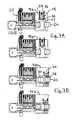
- a cylindrical rod or plunger, 73 here (as in all drawings) cut open through its vertical middle, enclasps a here shown divided and so lengthened (a whole long bar is here also possible) tailpiece/bar 64, thus rotationally reuniting it ( Fig. 7 A) .
- 73 is here shown having a hole 74 checked (filled) by a ferromagnetic rod 75 kept out by a spring 76 and released when, on command, a solenoid, 77, draws in 75; and which then allows rotation of the cylinder cum tailpiece (state a ).
- 73 is (ferromagnetic and) axially slideable along and over a gap in 64 and by spring 76 normally ( b ) in a position off the 64 rear extension thus, that even if the plug rotates, 64 won't. Only when ( a ), on command, - e.g. on reading a credentialed (and mechanically correct) key - solenoid 77 draws, that can happen.
- One version could be to remove the ordinary tailpiece and (from other side of the lock) make a matching tap go into or out of the, typically, slot in the cylinder rear end that is for holding the ordinary tailpiece ( Fig 8 ).
- a lock knob can be arranged as per above.
- the logical checking of credentialed keys is done by the sensing/evaluating/steering part(s) of the reader device according to the present invention.
- an antenna and adequate design, program etc.
- the keys can however be wanted encoded in other digital formats than cordlessly transferable, then bound to have galvanic contact points to electronic/logic parts, preferably at the key bow; and also here the method of this invention will work.
- Key 91 has a longer shoulder (92) than usual and continues then in ordinary way. On it needed contact point(s), 94, is (the metal of the blade can be another lead) /are put. Any needed number of points; and side of key is possible. (It could be noted that in Figs. 7 and 9-11 also a cordless clip (7) is shown on the key, because to the mechanical operation, the electronic code format is all one).
- a (mechanically correct) key isn't hindered from inserting, but, if not credentialed, hindered from operating the lock, the contact point(s) can make contact with the reader upon full insert.
- the keyway can be outwardly extended by two lips or a slot, wherein the corresponding contact leads, points etc. (610) from the electronic part of the reader device can reside.
- These parts (610) are preferably included in a cylinder ring (and rotate along with a key) rather than be put on the cylinder.
- the galvanic contact allows then for digital encoding formats not suitable for cordless transfer, as well as it can provide the possibly needed electric power (in lieu of batteries in the key) to the digital circuits of the key, preferably located in its bow. Needed power is very less and thus the reader device can supply, even if it self is battery powered (RFID/Wiegand on the other hand, don't need own power).
- a correct code has been conventionally read, processed and approved, a mechanism such as e.g. A of Fig. 7 is ordered to act. All of this can be done by distributed parts, but can also be included in e.g. a compound reader embodiment residing on the inside of the door, e.g. when rim locks and/or long range cordless formats are employed.
- the present invention can completely secure a retained cylinder lock by credentialing those keys that still remain with residents, relatives, house personell etc.; and if a mentioned motor/handle-mechanism is to be steered by some cord/cordtess "card" reader device, it is realized that a reader device of this invention can serve also that purpose; empowering a key for this code; and a motor, handle etc. for that.
- Same code carrier can be used for both systems and combinations/hybrids are possible, where a motor/handle mechanism employes one format, e.g.
- card/code, biometry, IR/RF, Blutooth/NFC, and a credentialed key employs other, corded/cordless (or both as in the drawings); or (also when used alone) has its own on board code carrier(s), complemented by exterior carrier(s), e.g. a Bluetooth/ NFC cellphone.
- One object of the present invention is to here provide a new, universally useable and “motoring” key device (10) for all the according to this embodiment of the invention reader-equipped locks, while at same time letting the locks' ordinary and individual as per the present invention credentialed keys work as before.
- FIG. 7 By slight modification of the reader device embodiments of Fig. 7 , one exemplary preferred reader device embodiment is rendered, which will accept both generic and individual as per this invention credentialed keys. With reference to Fig.11 and a separate key device, Fig.10 , one will be nearer described later below.
- a such key device (10) of this invention works on the fact that the keyway of esp a pin tumbler cylinder lock (and other types, such as disc tumbler ones, here meant included, alhough construction then may differ) is going all through the plug, ending by an arrangement, as e.g. and typically the one indicated in Fig.8 , for retaining a tailpiece, other driver bar or cam; and that, non with standing its folds, it is readily penetrated all through by a suited thin e.g. metal/plastic blade and/or an about 1 mm thick (cylindric) shaft.
- the tip (16) is separated from the blade (13) and instead like an arrow-head merged in an about 1 mm thick peg or shaft (15) which in its turn is fixed to the bow (11) while rotate-able going through the shoulder (12), thus rotating when 11 turns while 12 and its blade (13) stand still.
- Shaft 15 should be made from very strong material: metal, reinforced plastic, ceramics etc. (a one mm insex-key comes to mind for high torque); blade 13 is divided into two, supporting 11 and keeping the lock pins up for taking out the key.
- Length of a cylinder depends on number of pins (discs etc.), predominantly 5 or 7 pins (a difference of about 8 mm). Since this difference isn't discernible from the outside, a preferred key device embodiment should have such long blade that it can be fully inserted in the 7 pins (longest) cylinder, while being property stopped from further insert into the shortest one (as will be later herein expounded; Fig 10 , however, will just illustrate a key device proportioned to a 5 pins lock). For the corded code transfers contact points 94, this will have some design consequences (solvable, but not further herein treated), while cordless formats stay unaffected.
- Fig. 6 shows the all-pervading bottom L(+ inversion)-profiles of keyways, discernible from the outside.
- two versions of a key device 10 can be provided, one for each "L-course", which makes for a thicker and thus steadier blade bottom, better supporting the shaft and maybe eliminating need for a top blade part; the cylinder pins just slightly lifted when a here polled 16 goes in and out.
- Such variation is not here nearer described, just mentioned as example of possible variants which all are meant included in the present inventive thought.
- the front view ( Fig. 10b .) of tip and blade shows the thinner blade and thicker shaft.
- the arrow-head tip is forged in one solid piece whereas blade and peg are separate parts; the blade's two toungues flanking and supporting the peg. Behind, the thicker shoulder and the even thicker bow with clip are indicated.
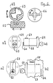
- Fig. 8 shows how a tailpiece usually looks and is held to the cylinder. It is thus perpendicular to the key and detach-ably held by a dip, thus replaceable by a to Fig. 7 similar contrivance and plunger device.
- rod 75 is filling out hole 74 of plunger 73, thus preventing both rotation and length movement, until activation.
- 73 is pressed against it by spring 76; and entering its holding slot 8 in the cylinder preferably just by two spikes 9, thus leaving its rear center area free for a slot formed after the "arrow-head" 16 and (with some tolerance) accepting its insertion to a predefined point.
- Bar 64 has just a hind part and 73 can slide along over it, always transferring any axial turn.
- a thereafter withdrawn 75 allows transfer of the cylinder's rotation (if hole 74 instead is a fittingly long groove in 73's periphery, it is seen that a mechanically correct, but not credentialed key can actuate instead, if so is desired); and when ( a , b ) an approved and generic according to this invention credentialed key device as of Fig 10 (not having any mechanical code cuts) wants to actuate the lock, a withdrawn 75 (a) also allows this, without any rotation of the cylinder, following procedures as below explained.
- the shoulder could have (not shown in Fig. 10 and apart from herein earlier disclosed features such as contact points) an enlarged portion facilitating holding it when inserting the key device into the lock.
- the "arrow-head" tip becomes fully inserted in the slot in 73 and thus, being flat, able to axially rotate same upon key (bow) turn, should not 73 be blocked.
- shoulder would in shorter cylinder versions not be fully inserted and measures as indicated earlier may be taken; functionality remains, though; and in Figs. 10-11 full insertion is assumed.
- the bow with rod has now an axial play vis-a-vis the shoulder the few mm:s it takes to free the e.g. spikes of 73 from the hold in the cylinder's holding slot; and is furthermore turnable vs. the shoulder but is blocked from utilizing these features by rod 75 ( Fig.11 b ). If however being credentialed for the lock, by own or separate means, e.g. a cellphone with NFC, 77/75 on proper command will release 73 and thus allow it to slide off its hold and transfer rotation to bar 64 upon pressing in and turning the key-bow; and this, then, without rotation of the cylinder ( Fig.11 a ).
- a shaft 11 can be freed for rotation (on 73 release) e.g. by sliding in vs. the key shoulder (as in in Fig 10 ), or further insert whole (not slideable vs. 12) key device.
- reverse function i. e. obstruction on power, is possible.
Abstract
A method is presented for credentialing - that is here lending EAC (Electronic Access Control) separate identity to - mechanical cylinder lock keys. The method primarily involves that both existing mechanical encoding, "cuts", of existing to locks pertaining keys as well as already in locks installed and existing lock cylinders pertaining to such keys can remain unchanged; that the key is provided with at least one appurtenant electronic code carrier, separate or on board the key, lending the key programmed individual and transmissible electronic signature(s) or characteristic(s), viz. credential(s); and that the lock cylinder is provided with a reader device, external to this and essentially unchanged cylinder, mentioned reader device having an electronic capacity for receiving, reading and reacting to the credential(s) of a key, as well as an electromechanical capacity to either block rotation of a cylinder or preventing rotation of a cylinder to result in actuation of a lock having a mentioned cylinder unless the cylinder and the reader have received a key having for actuation of the lock approved programmed credential(s); and also that lock actuation for a special credentialed key is possible even though the cylinder of that lock doesn't rotate.
Description
- This invention generally relates to access control; in one aspect to a new method for turning mechanic access control to "EAC" (Electronic Access Control) by converting existing mechanical cylinder lock keys to "smart" EAC keys without affecting their mechanic locking property and/or changing their respective existing lock cylinder; assisted by means of specifically designed and working credential readers, lending such keys and other new key devices, such credentials. The invention also relates to associated reader devices and key devices; one aspect is moreover for providing general EAC access for staff, e.g. home-care providers, as well as beside also maintaining individually defined EAC access for e.g. residents.
- The most common way to lock and unlock an access-controlling object such as a lock-provided door, is probably by using a mechanical key to both "decode" and "motor" the lock. This solution is cost-efficient and familiar to use: and sophisticated mechanical locks, esp. high security pin tumbler cylinder locks such as biaxial ones, are hard to force or pick, why such locks are recommended by authorities and often are granted incentives by insurance companies etc.. There is so all reason to keep this format; esp., of course, where already installed.
- However, there are also drawbacks with this solution, some of them serious. Mainly, the key doesn't have any restriction other then that it fits in its lock, i.e. it always work in that lock. This means that that a lost key cannot be incapacitated, other than by changing its belonging lock, which is costly and disturbing, esp. if many persons use that lock. The key also does not have any separate identity, so key abuse etc. becomes anonymous, thus untraceable to a specific source or incident; and thus corrective measures hardly be taken. If a large number of users, esp. staff, are involved, some sort of key administration is often needed.
- To overcome such and other disadvantages and still being able to keep the mechanical locks intact, mechanical keys' encodings have been substituted by EAC means such as cards and codes; and the "motor" action of the keys by motor means such as in e.g.
WO 2006/098690 , or "motoring" by the handle as e.g. inSE 529017 - There are in the art lock systems that open by combined mechanic and electronic so called hybrid keys; and where the the electronic part most often is in the key's bow as a circuit or at it as an RFID "tag". However, these systems cannot upgrade/retrofit most already in use locks/keys, which must be altogether newly purchased/installed; and the few locks that can be upgraded/retrofitted will have to change at least the essential active part, the cylinder, and also most often all keys, in order to be employed; and which all is costly and extensive. Prior art patents in this area are i.a.: (all US)
3,889,501 ;4,277,962 ;4,393,672 ;4,788,859 ;4,924,686 ;4,988,552 ;5,003,801 ;5,311,757 ;5,351,042 ;5,771,722 ;5,775,148 ;5,848,541 ;6,318,137 ;6,418,763 ;6,442,985 ;6,927,670 ;7,140,214 ;7,316,140 and7,397,343 . - It is object of the present invention to overcome such as above problems by, without changing the existing cylinders/keys, lending existing cylinder locks/keys both restriction and identity, i.e. credentialing them, by specifically equipping them; and in doing so, by the actions/influence of specifically designed reader devices, thus giving the keys/locks full EAC-capability as well as keeping the original keys' mechanical capability to actuate, "motor", their lock, thus eliminating the need for e.g. an electric motor. It is still object of the present invention to provide service staff with EAC-capable, universally usable, advantageous and facile to manage "motoring" key/reader devices for existing cylinder locks, while still offering like capacities also for individual, already existing mechanical keys for same locks.
-
-
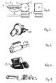
Fig. 1 shows a pin tumbler cylinder lock key in side and top view. -
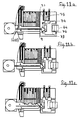
Fig. 2 shows a custom pin tumbler cylinder for rim and mortise locks. -
Fig. 3 shows a custom pin tumbler cylinder for key-in-knob(or lever) locks. -
Fig. 4 shows a custom pin tumbler cylinder mostly for mortise locks. -
Fig. 5 shows a custom arrangement for a cam of a cylinder for mortise locks. -
Fig. 6 shows custom fittings to a, here "oval", cylinder lock. -
Fig. 7 shows new contrivances to a cylinder lock according to the invention. -
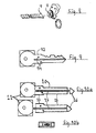
Fig. 8 shows a custom arrangement for a driver bar, "tailpiece", of a cylinder. -
Fig. 9 shows a for this invention modified individual key device in side view. -
Fig. 10 shows a generic key device according to one aspect of the invention. -
Fig. 11 shows a with a key device ofFig. 10 associated reader device(-part). - With reference to the drawings, preferred embodiments of the present invention will hereinafter be nearer explained, by means of example.
- The model key drawn in side and top view in
Fig. 1 shows a (pin tumbler) cylinder lock standard key with bow (1), shoulder (2), blade (3), keyway groves (4), mechanical encoding, "cuts" (5) and tip (6). In specific addition is at/in the bow of this here version put an RFID (or other code carrier format) circuit, here as a clip at the bow and through which the key is given individually programmable credentials (7). This can be done also as retrofit, and keys keeps their mechanical properties. - Also other cordless/proximity "card"/reader formats, e.g. Wiegand, can be employed; and key circuits included - in manufacture or by an authorized party at retrofit - in such a way that attempts to remove or replicate it, destroys it, thus in all making it impossible to unauthorizedly make or use duplicate (or pick) keys.
- The credentialing (cordless) code-carrier of/to a key can also be an external accessory, e.g. key holder, badge, Bluetooth/NFC(Near Field Communication)-enabled cellphone etc., still and in cooperation with a reader device of the present invention enabling only valid keys to open and/or lock; and all in a traceable way.
- A reader device according to herein described aspects and embodiments of this invention, is partly a reader (electronic) for e,g. RFID (or other employed code-carrier format) and partly a contrivance (electro-mechanical) for allowing key devices according to this invention to carry through a lock/unlock operation; and which not (as distinguished from prior art) in any way calls for changing a cylinder.
- With modem keys and locks; and most commonly pin tumbler cylinder locks, which here (not excluding other models) are chosen for non-limiting describing exemplary versions, highly secure, yet generic, uncomplicated, cost-efficient and advantageous rearrangements are realized through the present invention.
- These modern locks are quite modular and standardized so that the key accepting modules, in this here described case the lock cylinders, mechanically are very similar; and to move the lock bolt have a standard coupling arrangement (
Figs. 2-6 examples) linked thus to the lock bolt that when a cylinder rotates, bolt moves along (Fig. 6 exemplifies, among others, a common such ). The cylinder rotates by the key turn, not requiring, nor is the key capable of, much power. - However, to move the bolt from the inside (since a key cannot be inserted in the lock from that side) a so called lock knob is usually provided, which functions also when the cylinder stands still, by virtue of various arrangements whereof one is exemplary illustrated in
Fig. 6 . Now, if according to one preferred embodiment of this invention the cylinder is rotationally caught by a contrivance as exemplified inFig. 7A , an inserted, even mechanically correct, non-credentialed key is blocked from rotating the cylinder and thus operate the lock. At the same time, the lock knob can operate unaffected, as is also the case with a version exemplified below. - In such version, an example of which is rendered in
Fig. 7B , the cylinder can rotate, but only at command will such rotation be transfered to move the bolt. It can however in both these versions be sensed/alarmed etc. if an unauthorized party is attempting to enter; and an event log can be kept of all authorized entries. - The below nearer described embodiments, are electromechanical parts of a reader device embodiment, exemplary and non limiting herein disclosed; and are external to the cylinder and thus implementable without changing same. They are preferably always in catch respective disengagement by constructions as in
Fig. 7 A/B and release/catch by order of a reading part of the present invention when an according to this invention credentialed key inserts in the keyway of the cylinder. -
Figs. 2-5 are schematic and will just show/illustrate appearance etc. of some here employed locks. Of special interest here is the so called tailpiece 21 (64), which transfers the rotation of the cylinder via the coupling device to the lock bolt. - Also
Fig. 6 provides general background for herein described embodiments. In top view is seen astandard coupling device 61, and also how it can move abolt 62 upon rotating. From rear of the lock cylinder, "plug" 63, seen (with its "case") in front/back (a1/a2) and side (b1/b2) views, a bar, "tailpiece" 64, inserts halfway deep in thehole 65. From the other side of the door a, here cross-shaped, bar-end (66) from a lock knob inserts, also halfway deep. When plug turns (here 90°; other angles and thus other 61 constructions exist, but this description is intended to be exemplary also for such; and with from case to case dependent design variation), 61 will rotate, moving 62 along. Object and design of a coupling device, as 61, is, as noted in the art, to allow plug and door knob to actuate lock independently. - Matters as per above are according to hereinafter described embodiments, used for either deadlocking the plug, or uncoupling it from 61, for not credentialed keys. It should be stated that the in
Fig. 7 A/B illustrated electromechanical parts of a reader device embodiment according to the invention, are construed primarily for mortise locks and for simplicity (also to describe), yet demonstrating intended working to show and affirm the method's validity; and that other construction may be contrived, esp. for different types of locks, e.g. rim locks, "key-in-knob" locks. - Among the standard accessories to cylinder locks of here nearer described types, is a so called cylinder lengthener, which does merely what it is called. It is in
Fig. 6 indicated as 67 till the dottedline 68 which indicates where attached. It is inserted between the cylinder and thecoupling device 61, due to thick doors etc.; is about 10 mm thick and contains just an extension to/of 64. If the cylinder then gets so long that its front, with "keyway" 60, stretches out of the door, there are other standard accessories to envelope it, so called cylinder rings, 69, of various depths, which can cover any protruding (caused by insertion of 67; also then 69 can house a possible reader antenna, as well as later herein described galvanic contact points). These and other standard accessories or parts herein accounted for, are standardized and easy to insert and/or mount, also for an end user. - The described preferred embodiments A, 71 and B, 72 of
Fig. 7 , are shown in side view and axial top-to-bottom mid section; and are shown inserted in lieu of alengthener 67 to a cylinder also shown, with key and cylinder ring (69). They are shown in states a: lock operable and b: lock inoperable; for a mechanically correct key. The drawings are exemplary, schematic and illustrative; and dimensionally not exact, esp. 71/72 are greatly length exaggerated to facilitate illustrating their working. Whereas in these illustrated embodiments, the true length should be about 10 mm to correspond to a standard lengthener, a standard door aperture for a cylinder lock allows for much more radial (when rim locks also more longitudinal) space, which can be used to house parts of for these embodiments for mortise locks needed mechanisms, whereof two (71/72) are below nearer described. - A cylindrical rod or plunger, 73, here (as in all drawings) cut open through its vertical middle, enclasps a here shown divided and so lengthened (a whole long bar is here also possible) tailpiece/
bar 64, thus rotationally reuniting it (Fig. 7 A) . In b state, 73 is here shown having ahole 74 checked (filled) by aferromagnetic rod 75 kept out by aspring 76 and released when, on command, a solenoid, 77, draws in 75; and which then allows rotation of the cylinder cum tailpiece (state a). - In 7 B, 73 is (ferromagnetic and) axially slideable along and over a gap in 64 and by
spring 76 normally (b) in a position off the 64 rear extension thus, that even if the plug rotates, 64 won't. Only when (a), on command, - e.g. on reading a credentialed (and mechanically correct) key -solenoid 77 draws, that can happen. - Although solenoids here have been chosen for moving the parts, it is seen that other effectors and linkage, such as electric motors, bi/memory metal on impulse and heat, hydraulics, pneumatics etc., can work well also.
- These versions of the mechanically active parts of a reader device according to this invention, are to be placed at the cylinder side of a lock house and thus for space reasons preferably in a distributed installation, separate from other parts of the reader device, just needing impulse and power, e.g. electric, to work.
- Which of these versions (or possibly other constructions which will perform equivalent functions, e.g. a cam instead of a tailpiece to move the lock bolt; in 7B alter from, on activation, embracing the cylinder tailpiece part instead, e.g. by also then shifting solenoid's etc position towards the cylinder side; tailpiece's sectional view and thus also the sleeve's cavity of different shape; etc.) to chose, may be a matter of fitness; it is by above description seen and shown that functionality is as meant and that a lock knob will work well in both cases; and that any switch closure causation, such as e.g. sensing a credentialed key, may enact the device.
- More complicated and thus not preferred, would be to place functionally similar arrangements at the lock knob side of the (mortise) lock house. Still, they are possible and there might be instances where they will fit; and thus a brief on two such versions will be given. There are in the market standard cylinders with extra long tailpiece; and also tailpieces are very easy to change by just loosening a clip (
Fig. 8 ). A long bar can pass 65 and be checked/released at the other side. For a lock knob, some fork-like arrangement can be contrived. - To disengage from the cylinder is also possible. One version could be to remove the ordinary tailpiece and (from other side of the lock) make a matching tap go into or out of the, typically, slot in the cylinder rear end that is for holding the ordinary tailpiece (
Fig 8 ). For a lock knob can be arranged as per above. - Whereas the disclosed key enabling mechanisms just need an on/off command to act, the logical checking of credentialed keys, i.a. for giving relevant such command, is done by the sensing/evaluating/steering part(s) of the reader device according to the present invention. By an antenna (and adequate design, program etc.) it can read the credentials of a key cordlessly, when key is inserting. The keys can however be wanted encoded in other digital formats than cordlessly transferable, then bound to have galvanic contact points to electronic/logic parts, preferably at the key bow; and also here the method of this invention will work.
- When an existing key is to be exchanged for a credentialed one, one can start from a key blank; and then keep same mechanical pattern, cuts, whereas a needed variance for putting galvanic contact points can be done at key shoulder.
- With reference to
Fig. 9 , an exemplary preferred embodiment will now be described. Key 91 has a longer shoulder (92) than usual and continues then in ordinary way. On it needed contact point(s), 94, is (the metal of the blade can be another lead) /are put. Any needed number of points; and side of key is possible. (It could be noted that inFigs. 7 and9-11 also a cordless clip (7) is shown on the key, because to the mechanical operation, the electronic code format is all one). - Since according to described embodiments of this invention, a (mechanically correct) key isn't hindered from inserting, but, if not credentialed, hindered from operating the lock, the contact point(s) can make contact with the reader upon full insert. Thus, the keyway can be outwardly extended by two lips or a slot, wherein the corresponding contact leads, points etc. (610) from the electronic part of the reader device can reside. These parts (610) are preferably included in a cylinder ring (and rotate along with a key) rather than be put on the cylinder.
- The galvanic contact allows then for digital encoding formats not suitable for cordless transfer, as well as it can provide the possibly needed electric power (in lieu of batteries in the key) to the digital circuits of the key, preferably located in its bow. Needed power is very less and thus the reader device can supply, even if it self is battery powered (RFID/Wiegand on the other hand, don't need own power).
- When, in any version (the parts indicated as 610 in he
cylinder ring 69, can stand for leads for corded formats; and as antenna for cordless formats), a correct code has been conventionally read, processed and approved, a mechanism such as e.g. A ofFig. 7 is ordered to act. All of this can be done by distributed parts, but can also be included in e.g. a compound reader embodiment residing on the inside of the door, e.g. when rim locks and/or long range cordless formats are employed. - In systems such as
WO 2006/098690 andSE 529017 - To be able to eliminate a need for expensive and complicated motor/handle etc. devices and overall rely on the 'motoring' of a mechanical key, would be a great advantage. But motive for systems like
WO 2006/098690 is to eliminate need for complex key administration and handling which staff, like e.g. home-care nurses, meet when visiting a number of residences with between themselves different locks; and thus, absent such systems, have to carry a lot of different keys. - One object of the present invention is to here provide a new, universally useable and "motoring" key device (10) for all the according to this embodiment of the invention reader-equipped locks, while at same time letting the locks' ordinary and individual as per the present invention credentialed keys work as before.
- To move a lock cylinder mechanicly, its key must have the right cuts. One for different locks working key, though, cannot possibly have the cuts to be able to move those different cylinders. Thus it must be able to work over a static cylinder.
- By slight modification of the reader device embodiments of
Fig. 7 , one exemplary preferred reader device embodiment is rendered, which will accept both generic and individual as per this invention credentialed keys. With reference toFig.11 and a separate key device,Fig.10 , one will be nearer described later below. - A such key device (10) of this invention, one preferred embodiment of which is illustrated in
Fig.10 and shown equipped for both corded and cordless formats, works on the fact that the keyway of esp a pin tumbler cylinder lock (and other types, such as disc tumbler ones, here meant included, alhough construction then may differ) is going all through the plug, ending by an arrangement, as e.g. and typically the one indicated inFig.8 , for retaining a tailpiece, other driver bar or cam; and that, non with standing its folds, it is readily penetrated all through by a suited thin e.g. metal/plastic blade and/or an about 1 mm thick (cylindric) shaft. - In a key's way are the pins (or discs etc.) which are passed by the beveled key tip/cuts; and thus to allow all-through passage, all pins (etc.) must be able to go up and away enough from the keyway, although, as well known in he art, they typically won't allow the cylinder to rotate when they all are in such position.
- Thus, as can be seen in side wiew (a) in
Fig. 10 , the there exemplified and preferred embodiment of a key device according to this invention, has eliminated all cuts, thus making it universal for all locks of a kind. Since pin tumbler locks are practically the only type now installed at residencies etc.; and moreover are of very similar, almost standardized proportions, one or very few key devices of this here described type should suffice for an area, district, province etc., just having to (with some tolerance) fit into a keyway and work in spite of that a cylinder won't rotate. - According to described embodiment the tip (16) is separated from the blade (13) and instead like an arrow-head merged in an about 1 mm thick peg or shaft (15) which in its turn is fixed to the bow (11) while rotate-able going through the shoulder (12), thus rotating when 11 turns while 12 and its blade (13) stand still.
-
Shaft 15 should be made from very strong material: metal, reinforced plastic, ceramics etc. (a one mm insex-key comes to mind for high torque);blade 13 is divided into two, supporting 11 and keeping the lock pins up for taking out the key. - Length of a cylinder depends on number of pins (discs etc.), predominantly 5 or 7 pins (a difference of about 8 mm). Since this difference isn't discernible from the outside, a preferred key device embodiment should have such long blade that it can be fully inserted in the 7 pins (longest) cylinder, while being property stopped from further insert into the shortest one (as will be later herein expounded;
Fig 10 , however, will just illustrate a key device proportioned to a 5 pins lock). For the corded code transfers contact points 94, this will have some design consequences (solvable, but not further herein treated), while cordless formats stay unaffected. -
Fig. 6 shows the all-pervading bottom L(+ inversion)-profiles of keyways, discernible from the outside. Taking that into account, two versions of akey device 10 can be provided, one for each "L-course", which makes for a thicker and thus steadier blade bottom, better supporting the shaft and maybe eliminating need for a top blade part; the cylinder pins just slightly lifted when a here polled 16 goes in and out. Such variation is not here nearer described, just mentioned as example of possible variants which all are meant included in the present inventive thought. - The front view (
Fig. 10b .) of tip and blade, shows the thinner blade and thicker shaft. The arrow-head tip is forged in one solid piece whereas blade and peg are separate parts; the blade's two toungues flanking and supporting the peg. Behind, the thicker shoulder and the even thicker bow with clip are indicated. - To further explain the working, reference is now made to
Fig. 11 a, b and c.Fig. 8 shows how a tailpiece usually looks and is held to the cylinder. It is thus perpendicular to the key and detach-ably held by a dip, thus replaceable by a toFig. 7 similar contrivance and plunger device. In a version resemblingFig. 7A ,rod 75 is filling outhole 74 ofplunger 73, thus preventing both rotation and length movement, until activation. Instead of held by a clip (if clip also held the cylinder, a clip with just such function should substitute), 73 is pressed against it byspring 76; and entering itsholding slot 8 in the cylinder preferably just by twospikes 9, thus leaving its rear center area free for a slot formed after the "arrow-head" 16 and (with some tolerance) accepting its insertion to a predefined point.Bar 64 has just a hind part and 73 can slide along over it, always transferring any axial turn. - As (
Fig.11 c) an approved and individual as per this invention credentialed key, having also the right mechanical code cuts, enters, a thereafter withdrawn 75 allows transfer of the cylinder's rotation (ifhole 74 instead is a fittingly long groove in 73's periphery, it is seen that a mechanically correct, but not credentialed key can actuate instead, if so is desired); and when (a, b) an approved and generic according to this invention credentialed key device as ofFig 10 (not having any mechanical code cuts) wants to actuate the lock, a withdrawn 75 (a) also allows this, without any rotation of the cylinder, following procedures as below explained. - The shoulder could have (not shown in
Fig. 10 and apart from herein earlier disclosed features such as contact points) an enlarged portion facilitating holding it when inserting the key device into the lock. When the key blade stops at the cylinder end (when 73 still is not released), the "arrow-head" tip becomes fully inserted in the slot in 73 and thus, being flat, able to axially rotate same upon key (bow) turn, should not 73 be blocked. (If a for varying number of pin tumblers version, as earlier herein discussed, is employed, shoulder would in shorter cylinder versions not be fully inserted and measures as indicated earlier may be taken; functionality remains, though; and inFigs. 10-11 full insertion is assumed.) - The bow with rod has now an axial play vis-a-vis the shoulder the few mm:s it takes to free the e.g. spikes of 73 from the hold in the cylinder's holding slot; and is furthermore turnable vs. the shoulder but is blocked from utilizing these features by rod 75 (
Fig.11 b). If however being credentialed for the lock, by own or separate means, e.g. a cellphone with NFC, 77/75 on proper command will release 73 and thus allow it to slide off its hold and transfer rotation to bar 64 upon pressing in and turning the key-bow; and this, then, without rotation of the cylinder (Fig.11 a). - If a latchbolt lock is present, the key most often revolves back automatically and can be immediately taken out; if a deadbolt lock is present, the key will have to be turned back for being taken out and also the lock has to be actively relocked; in all cases, 73 and its slot (and door knob) will come right for any next operation.
- To be able - and esp. with mortise and key-in-knob locks - to work within an actual, likely restrained longitudinal room - about 10 mm for a standard cylinder lengthener and possible cylinder ring further extension - may in some respects call for precision "clockwork" techniques and strong materials, however in relation to to-day's nano technology still in a macro format and fully achievable/available. To avoid over-stress on a
shaft 11, for instance, it can be attached to its key bow per a friction coupling, if an enough strong material for it unlikely isn't found. Also, a cylinder lock should not need much force to actuate; if obstructing, the problem is normally in the door, and the familiar remedy is to treatlpush/pull/etc. the same. Ashaft 11 can be freed for rotation (on 73 release) e.g. by sliding in vs. the key shoulder (as in inFig 10 ), or further insert whole (not slideable vs. 12) key device. For emergency exits etc., reverse function, i. e. obstruction on power, is possible. - The preceding disclosure is for practical reasons held in relation mostly to tailpieces/bars for driving the bolt and allow for a door knob (esp. with mortise locks; most rim- and key-in-knob locks will have arrangements for a such inbuilt); and it is from
Figs. 2-6 seen that a tailpiece/driver bar (with case-to-case measure modification) is being commonly employed for rim, mortise as well as key-in-knob locks. Some mortise locks use a cam in lieu of a tailpiece (Fig. 5 ) to move the bolt. It is seen, but not herein nearer unfolded, that arrangements analogous and/or similar to earlier herein explained contrivances can be made also for a cam, being in effect merely a form/shape variant of an ordinary tailpiece/driver bar. - For i.a. such reasons, the here presented drawings, nearer description etc. have been done in most general terms. The disclosed methodology allows, and variety of custom locks calls, for much variance in exact (electro)mechanical and electronic construction. Parts of or whole lock devices can be factory ready-made, or retrofits by parts effected at site. It is thus to be understood that the disclosure herein, apart from providing a base for the pending claims, is of a non limiting, for the skilled person explaining and illustrating, nature mostly; and that based on this disclosure and given insight, at least the skilled person is enabled to range quite much, but without so departing from the present inventive thought and claims.
Claims (3)
- Method for credentialing, that is here lending EAC (Electronic Access Control) separate identity to, mechanical cylinder lock keys, characterized in,
that both existing mechanical encoding, "cuts", of existing to locks pertaining keys as well as already in locks installed and existing lock cylinders pertaining to said keys can remain unchanged;
that a said key is provided with at least one appurtenant electronic code carrier, separate or on board the said key, lending the said key programmed individual and transmissible electronic signature(s) or characteristic(s), viz. "credential(s)";
that a said lock cylinder is provided with a reader device, external to said and essentially unchanged cylinder, said reader device having an electronic capacity for receiving, reading and reacting to the said credential(s) of a said key, as well as an electromechanical capacity to either block rotation of a said cylinder or preventing rotation of a said cylinder to result in actuation of a lock having a said cylinder unless said cylinder and said reader have received a said key having for actuation of said lock approved said programmed credentlal(s). - Method according to cairn 1, further characterized in that a said key (10) not needing any said cuts by means of direct mechanic coupling to a said lock right through a non rotating said cylinder of said lock can actuate said lock when properly inserted and handled and having for actuation of said lock approved said programmed credential(s).
- Method according to claim 2, wherein a key having proper said mechanical cuts nonwithstanding lacking said credential(s) can actuate said lock.
Applications Claiming Priority (1)
| Application Number | Priority Date | Filing Date | Title |
|---|---|---|---|
| SE0801538 | 2008-06-30 |
Publications (1)
| Publication Number | Publication Date |
|---|---|
| EP2141663A2 true EP2141663A2 (en) | 2010-01-06 |
Family
ID=41320101
Family Applications (1)
| Application Number | Title | Priority Date | Filing Date |
|---|---|---|---|
| EP20090008393 Withdrawn EP2141663A2 (en) | 2008-06-30 | 2009-06-26 | Method for credentialing mechanical keys and associated devices |
Country Status (1)
| Country | Link |
|---|---|
| EP (1) | EP2141663A2 (en) |
Cited By (3)
| Publication number | Priority date | Publication date | Assignee | Title |
|---|---|---|---|---|
| CN103895939A (en) * | 2012-12-26 | 2014-07-02 | 中钞海思信息技术(北京)有限公司 | Self-locking prevention type banknote transport bag device |
| DE102015113416A1 (en) * | 2015-08-14 | 2017-02-16 | Assa Abloy Sicherheitstechnik Gmbh | Key for an Electronic or Mechatronic Lock Key System and Lock Key System for a Key |
| EP3289152A4 (en) * | 2015-04-30 | 2019-01-02 | Bryan Michael Risi | Actuating assembly for a latching system |
Citations (21)
| Publication number | Priority date | Publication date | Assignee | Title |
|---|---|---|---|---|
| US3889501A (en) | 1973-08-14 | 1975-06-17 | Charles P Fort | Combination electrical and mechanical lock system |
| US4277962A (en) | 1978-06-06 | 1981-07-14 | Neiman Sa | Device for blocking key passage of a lock |
| US4393672A (en) | 1978-12-13 | 1983-07-19 | Egon Gelhard | Cylinder lock and key assembly |
| US4788859A (en) | 1987-11-13 | 1988-12-06 | Khattak Anwar S | Method and apparatus for determining deflection in pavement |
| US4924686A (en) | 1987-02-09 | 1990-05-15 | R. Berchtold Ag | Contact device for transmitting electrical signals between a lock and key in a cylinder lock |
| US4988552A (en) | 1988-06-17 | 1991-01-29 | Composite Concepts Company | Electrical discharge machining electrode |
| US5003801A (en) | 1987-01-20 | 1991-04-02 | Ford Motor Company | Programmable key and improved lock assembly |
| US5311757A (en) | 1992-03-06 | 1994-05-17 | Aug. Winkhaus Gmbh & Co. Kg | Flat key with circuit chip |
| US5351042A (en) | 1991-03-19 | 1994-09-27 | Yale Security Products Limited | Lock, key and combination of lock and key |
| US5771722A (en) | 1993-11-12 | 1998-06-30 | Kaba High Security Locks Corporation | Dual control mode lock system |
| US5775148A (en) | 1995-03-16 | 1998-07-07 | Medeco Security Locks, Inc. | Universal apparatus for use with electronic and/or mechanical access control devices |
| US5848541A (en) | 1994-03-30 | 1998-12-15 | Dallas Semiconductor Corporation | Electrical/mechanical access control systems |
| US6318137B1 (en) | 1998-04-08 | 2001-11-20 | David Chaum | Electronic lock that can learn to recognize any ordinary key |
| US6418763B1 (en) | 2001-01-16 | 2002-07-16 | Tsun Thin Huang | Electronic chip functioned lock |
| US6442985B1 (en) | 1999-06-11 | 2002-09-03 | Nissan Motor Co., Ltd. | Lock apparatus and lock system |
| US6927670B1 (en) | 1992-02-14 | 2005-08-09 | Security People, Inc. | Conventional mechanical lock cylinders and keys with electronic access control feature |
| WO2006098690A1 (en) | 2005-03-18 | 2006-09-21 | Phoniro Ab | A method for unlocking a lock by a lock device enabled for short-range wireless data communication in compliance with a communication standard, and associated devices |
| US7140214B2 (en) | 2002-04-11 | 2006-11-28 | Ruko A/S | Electro-mechanical cylinder lock-key combination with optical code |
| SE529017C2 (en) | 2004-02-10 | 2007-04-10 | Lars Mattson | Lock for doors, has electrically activated device for mechanically connecting handles to latch |
| US7316140B2 (en) | 1998-04-07 | 2008-01-08 | Stanley Security Solutions, Inc. | Electronic token and lock core |
| US7397343B1 (en) | 1992-02-14 | 2008-07-08 | Security People, Inc. | Conventional mechanical lock cylinders and keys with electronic access control feature |
-
2009
- 2009-06-26 EP EP20090008393 patent/EP2141663A2/en not_active Withdrawn
Patent Citations (21)
| Publication number | Priority date | Publication date | Assignee | Title |
|---|---|---|---|---|
| US3889501A (en) | 1973-08-14 | 1975-06-17 | Charles P Fort | Combination electrical and mechanical lock system |
| US4277962A (en) | 1978-06-06 | 1981-07-14 | Neiman Sa | Device for blocking key passage of a lock |
| US4393672A (en) | 1978-12-13 | 1983-07-19 | Egon Gelhard | Cylinder lock and key assembly |
| US5003801A (en) | 1987-01-20 | 1991-04-02 | Ford Motor Company | Programmable key and improved lock assembly |
| US4924686A (en) | 1987-02-09 | 1990-05-15 | R. Berchtold Ag | Contact device for transmitting electrical signals between a lock and key in a cylinder lock |
| US4788859A (en) | 1987-11-13 | 1988-12-06 | Khattak Anwar S | Method and apparatus for determining deflection in pavement |
| US4988552A (en) | 1988-06-17 | 1991-01-29 | Composite Concepts Company | Electrical discharge machining electrode |
| US5351042A (en) | 1991-03-19 | 1994-09-27 | Yale Security Products Limited | Lock, key and combination of lock and key |
| US6927670B1 (en) | 1992-02-14 | 2005-08-09 | Security People, Inc. | Conventional mechanical lock cylinders and keys with electronic access control feature |
| US7397343B1 (en) | 1992-02-14 | 2008-07-08 | Security People, Inc. | Conventional mechanical lock cylinders and keys with electronic access control feature |
| US5311757A (en) | 1992-03-06 | 1994-05-17 | Aug. Winkhaus Gmbh & Co. Kg | Flat key with circuit chip |
| US5771722A (en) | 1993-11-12 | 1998-06-30 | Kaba High Security Locks Corporation | Dual control mode lock system |
| US5848541A (en) | 1994-03-30 | 1998-12-15 | Dallas Semiconductor Corporation | Electrical/mechanical access control systems |
| US5775148A (en) | 1995-03-16 | 1998-07-07 | Medeco Security Locks, Inc. | Universal apparatus for use with electronic and/or mechanical access control devices |
| US7316140B2 (en) | 1998-04-07 | 2008-01-08 | Stanley Security Solutions, Inc. | Electronic token and lock core |
| US6318137B1 (en) | 1998-04-08 | 2001-11-20 | David Chaum | Electronic lock that can learn to recognize any ordinary key |
| US6442985B1 (en) | 1999-06-11 | 2002-09-03 | Nissan Motor Co., Ltd. | Lock apparatus and lock system |
| US6418763B1 (en) | 2001-01-16 | 2002-07-16 | Tsun Thin Huang | Electronic chip functioned lock |
| US7140214B2 (en) | 2002-04-11 | 2006-11-28 | Ruko A/S | Electro-mechanical cylinder lock-key combination with optical code |
| SE529017C2 (en) | 2004-02-10 | 2007-04-10 | Lars Mattson | Lock for doors, has electrically activated device for mechanically connecting handles to latch |
| WO2006098690A1 (en) | 2005-03-18 | 2006-09-21 | Phoniro Ab | A method for unlocking a lock by a lock device enabled for short-range wireless data communication in compliance with a communication standard, and associated devices |
Cited By (4)
| Publication number | Priority date | Publication date | Assignee | Title |
|---|---|---|---|---|
| CN103895939A (en) * | 2012-12-26 | 2014-07-02 | 中钞海思信息技术(北京)有限公司 | Self-locking prevention type banknote transport bag device |
| CN103895939B (en) * | 2012-12-26 | 2016-08-03 | 中钞海思信息技术(北京)有限公司 | Anti-self-locking type fortune paper money bagging apparatus |
| EP3289152A4 (en) * | 2015-04-30 | 2019-01-02 | Bryan Michael Risi | Actuating assembly for a latching system |
| DE102015113416A1 (en) * | 2015-08-14 | 2017-02-16 | Assa Abloy Sicherheitstechnik Gmbh | Key for an Electronic or Mechatronic Lock Key System and Lock Key System for a Key |
Similar Documents
| Publication | Publication Date | Title |
|---|---|---|
| EP1250505B1 (en) | Electronic locking system | |
| US10378244B2 (en) | Locking device with configurable electrical connector key and internal circuit board for electronic door locks | |
| US8973417B2 (en) | Electronically-controlled removable core lock | |
| US6227020B1 (en) | Locking device | |
| JP5331199B2 (en) | Passive electronic cylinder lock that operates with minute power | |
| EP1366255B1 (en) | Electronic locking system | |
| US6000609A (en) | Mechanical/electronic lock and key therefor | |
| AU730340B2 (en) | Electromechanical cylinder lock with rotary release | |
| US6840072B2 (en) | Electronic token and lock core | |
| EP1490571B1 (en) | Electronic locking system with emergency exit feature | |
| US8225629B2 (en) | Portable lock with electronic lock actuator | |
| EP2570574B1 (en) | Solenoid operated electromechanical lock | |
| CZ294948B6 (en) | Method for controlling access to a plurality of enclosures, electronic safe deposit box system and electronic door locking apparatus | |
| US20180112437A1 (en) | Motor with mounted printed circuit board for electronic lock | |
| EP2141663A2 (en) | Method for credentialing mechanical keys and associated devices | |
| CA2920552C (en) | Locking device with configurable electrical connector key and internal circuit board for electronic door locks | |
| WO2015065944A1 (en) | Electromechanical lock cylinder | |
| JP5296363B2 (en) | Surface lock | |
| EP3880910B1 (en) | Lock cylinder | |
| JPWO2008069210A1 (en) | Lockbox with key | |
| US20080178649A1 (en) | Lock with indicator and multiple key-operable core | |
| EP3263810B1 (en) | History management system of electronic locking apparatus | |
| AU2017100470A4 (en) | An Improved Lock and Lock Module | |
| EP3270357A1 (en) | Electronic lock | |
| FI125740B (en) | Arrangement for locking the door |
Legal Events
| Date | Code | Title | Description |
|---|---|---|---|
| PUAI | Public reference made under article 153(3) epc to a published international application that has entered the european phase |
Free format text: ORIGINAL CODE: 0009012 |
|
| AK | Designated contracting states |
Kind code of ref document: A2 Designated state(s): AT BE BG CH CY CZ DE DK EE ES FI FR GB GR HR HU IE IS IT LI LT LU LV MC MK MT NL NO PL PT RO SE SI SK TR |
|
| STAA | Information on the status of an ep patent application or granted ep patent |
Free format text: STATUS: THE APPLICATION IS DEEMED TO BE WITHDRAWN |
|
| 18D | Application deemed to be withdrawn |
Effective date: 20120103 |