EP2135576A1 - Method for modelling a glenoidal surface of a scapula, device for implanting a glenoidal component of a shoulder prosthesis, and method for manufacturing such a component - Google Patents
Method for modelling a glenoidal surface of a scapula, device for implanting a glenoidal component of a shoulder prosthesis, and method for manufacturing such a component Download PDFInfo
- Publication number
- EP2135576A1 EP2135576A1 EP20090163299 EP09163299A EP2135576A1 EP 2135576 A1 EP2135576 A1 EP 2135576A1 EP 20090163299 EP20090163299 EP 20090163299 EP 09163299 A EP09163299 A EP 09163299A EP 2135576 A1 EP2135576 A1 EP 2135576A1
- Authority
- EP
- European Patent Office
- Prior art keywords
- glenoid
- ellipsoid
- scapula
- glenoid surface
- theoretical
- Prior art date
- Legal status (The legal status is an assumption and is not a legal conclusion. Google has not performed a legal analysis and makes no representation as to the accuracy of the status listed.)
- Granted
Links
- GZUQTPOOVKYEES-UHFFFAOYSA-N CC(C1)(C1NC)[IH][IH]C Chemical compound CC(C1)(C1NC)[IH][IH]C GZUQTPOOVKYEES-UHFFFAOYSA-N 0.000 description 1
Images


Classifications
-
- A—HUMAN NECESSITIES
- A61—MEDICAL OR VETERINARY SCIENCE; HYGIENE
- A61B—DIAGNOSIS; SURGERY; IDENTIFICATION
- A61B90/00—Instruments, implements or accessories specially adapted for surgery or diagnosis and not covered by any of the groups A61B1/00 - A61B50/00, e.g. for luxation treatment or for protecting wound edges
- A61B90/36—Image-producing devices or illumination devices not otherwise provided for
-
- A—HUMAN NECESSITIES
- A61—MEDICAL OR VETERINARY SCIENCE; HYGIENE
- A61F—FILTERS IMPLANTABLE INTO BLOOD VESSELS; PROSTHESES; DEVICES PROVIDING PATENCY TO, OR PREVENTING COLLAPSING OF, TUBULAR STRUCTURES OF THE BODY, e.g. STENTS; ORTHOPAEDIC, NURSING OR CONTRACEPTIVE DEVICES; FOMENTATION; TREATMENT OR PROTECTION OF EYES OR EARS; BANDAGES, DRESSINGS OR ABSORBENT PADS; FIRST-AID KITS
- A61F2/00—Filters implantable into blood vessels; Prostheses, i.e. artificial substitutes or replacements for parts of the body; Appliances for connecting them with the body; Devices providing patency to, or preventing collapsing of, tubular structures of the body, e.g. stents
- A61F2/02—Prostheses implantable into the body
- A61F2/30—Joints
- A61F2/3094—Designing or manufacturing processes
- A61F2/30942—Designing or manufacturing processes for designing or making customized prostheses, e.g. using templates, CT or NMR scans, finite-element analysis or CAD-CAM techniques
-
- A—HUMAN NECESSITIES
- A61—MEDICAL OR VETERINARY SCIENCE; HYGIENE
- A61F—FILTERS IMPLANTABLE INTO BLOOD VESSELS; PROSTHESES; DEVICES PROVIDING PATENCY TO, OR PREVENTING COLLAPSING OF, TUBULAR STRUCTURES OF THE BODY, e.g. STENTS; ORTHOPAEDIC, NURSING OR CONTRACEPTIVE DEVICES; FOMENTATION; TREATMENT OR PROTECTION OF EYES OR EARS; BANDAGES, DRESSINGS OR ABSORBENT PADS; FIRST-AID KITS
- A61F2/00—Filters implantable into blood vessels; Prostheses, i.e. artificial substitutes or replacements for parts of the body; Appliances for connecting them with the body; Devices providing patency to, or preventing collapsing of, tubular structures of the body, e.g. stents
- A61F2/02—Prostheses implantable into the body
- A61F2/30—Joints
- A61F2/40—Joints for shoulders
- A61F2/4081—Glenoid components, e.g. cups
-
- A—HUMAN NECESSITIES
- A61—MEDICAL OR VETERINARY SCIENCE; HYGIENE
- A61F—FILTERS IMPLANTABLE INTO BLOOD VESSELS; PROSTHESES; DEVICES PROVIDING PATENCY TO, OR PREVENTING COLLAPSING OF, TUBULAR STRUCTURES OF THE BODY, e.g. STENTS; ORTHOPAEDIC, NURSING OR CONTRACEPTIVE DEVICES; FOMENTATION; TREATMENT OR PROTECTION OF EYES OR EARS; BANDAGES, DRESSINGS OR ABSORBENT PADS; FIRST-AID KITS
- A61F2/00—Filters implantable into blood vessels; Prostheses, i.e. artificial substitutes or replacements for parts of the body; Appliances for connecting them with the body; Devices providing patency to, or preventing collapsing of, tubular structures of the body, e.g. stents
- A61F2/02—Prostheses implantable into the body
- A61F2/30—Joints
- A61F2/46—Special tools or methods for implanting or extracting artificial joints, accessories, bone grafts or substitutes, or particular adaptations therefor
- A61F2/4603—Special tools or methods for implanting or extracting artificial joints, accessories, bone grafts or substitutes, or particular adaptations therefor for insertion or extraction of endoprosthetic joints or of accessories thereof
- A61F2/4612—Special tools or methods for implanting or extracting artificial joints, accessories, bone grafts or substitutes, or particular adaptations therefor for insertion or extraction of endoprosthetic joints or of accessories thereof of shoulders
-
- A—HUMAN NECESSITIES
- A61—MEDICAL OR VETERINARY SCIENCE; HYGIENE
- A61F—FILTERS IMPLANTABLE INTO BLOOD VESSELS; PROSTHESES; DEVICES PROVIDING PATENCY TO, OR PREVENTING COLLAPSING OF, TUBULAR STRUCTURES OF THE BODY, e.g. STENTS; ORTHOPAEDIC, NURSING OR CONTRACEPTIVE DEVICES; FOMENTATION; TREATMENT OR PROTECTION OF EYES OR EARS; BANDAGES, DRESSINGS OR ABSORBENT PADS; FIRST-AID KITS
- A61F2/00—Filters implantable into blood vessels; Prostheses, i.e. artificial substitutes or replacements for parts of the body; Appliances for connecting them with the body; Devices providing patency to, or preventing collapsing of, tubular structures of the body, e.g. stents
- A61F2/02—Prostheses implantable into the body
- A61F2/30—Joints
- A61F2/46—Special tools or methods for implanting or extracting artificial joints, accessories, bone grafts or substitutes, or particular adaptations therefor
- A61F2/4657—Measuring instruments used for implanting artificial joints
-
- G—PHYSICS
- G06—COMPUTING; CALCULATING OR COUNTING
- G06T—IMAGE DATA PROCESSING OR GENERATION, IN GENERAL
- G06T17/00—Three dimensional [3D] modelling, e.g. data description of 3D objects
- G06T17/05—Geographic models
-
- G—PHYSICS
- G06—COMPUTING; CALCULATING OR COUNTING
- G06T—IMAGE DATA PROCESSING OR GENERATION, IN GENERAL
- G06T17/00—Three dimensional [3D] modelling, e.g. data description of 3D objects
- G06T17/30—Polynomial surface description
-
- A—HUMAN NECESSITIES
- A61—MEDICAL OR VETERINARY SCIENCE; HYGIENE
- A61B—DIAGNOSIS; SURGERY; IDENTIFICATION
- A61B34/00—Computer-aided surgery; Manipulators or robots specially adapted for use in surgery
- A61B34/20—Surgical navigation systems; Devices for tracking or guiding surgical instruments, e.g. for frameless stereotaxis
- A61B2034/2068—Surgical navigation systems; Devices for tracking or guiding surgical instruments, e.g. for frameless stereotaxis using pointers, e.g. pointers having reference marks for determining coordinates of body points
-
- A—HUMAN NECESSITIES
- A61—MEDICAL OR VETERINARY SCIENCE; HYGIENE
- A61B—DIAGNOSIS; SURGERY; IDENTIFICATION
- A61B34/00—Computer-aided surgery; Manipulators or robots specially adapted for use in surgery
- A61B34/20—Surgical navigation systems; Devices for tracking or guiding surgical instruments, e.g. for frameless stereotaxis
-
- A—HUMAN NECESSITIES
- A61—MEDICAL OR VETERINARY SCIENCE; HYGIENE
- A61F—FILTERS IMPLANTABLE INTO BLOOD VESSELS; PROSTHESES; DEVICES PROVIDING PATENCY TO, OR PREVENTING COLLAPSING OF, TUBULAR STRUCTURES OF THE BODY, e.g. STENTS; ORTHOPAEDIC, NURSING OR CONTRACEPTIVE DEVICES; FOMENTATION; TREATMENT OR PROTECTION OF EYES OR EARS; BANDAGES, DRESSINGS OR ABSORBENT PADS; FIRST-AID KITS
- A61F2/00—Filters implantable into blood vessels; Prostheses, i.e. artificial substitutes or replacements for parts of the body; Appliances for connecting them with the body; Devices providing patency to, or preventing collapsing of, tubular structures of the body, e.g. stents
- A61F2/02—Prostheses implantable into the body
- A61F2/30—Joints
- A61F2/30767—Special external or bone-contacting surface, e.g. coating for improving bone ingrowth
- A61F2/30771—Special external or bone-contacting surface, e.g. coating for improving bone ingrowth applied in original prostheses, e.g. holes or grooves
- A61F2002/30878—Special external or bone-contacting surface, e.g. coating for improving bone ingrowth applied in original prostheses, e.g. holes or grooves with non-sharp protrusions, for instance contacting the bone for anchoring, e.g. keels, pegs, pins, posts, shanks, stems, struts
- A61F2002/30884—Fins or wings, e.g. longitudinal wings for preventing rotation within the bone cavity
-
- A—HUMAN NECESSITIES
- A61—MEDICAL OR VETERINARY SCIENCE; HYGIENE
- A61F—FILTERS IMPLANTABLE INTO BLOOD VESSELS; PROSTHESES; DEVICES PROVIDING PATENCY TO, OR PREVENTING COLLAPSING OF, TUBULAR STRUCTURES OF THE BODY, e.g. STENTS; ORTHOPAEDIC, NURSING OR CONTRACEPTIVE DEVICES; FOMENTATION; TREATMENT OR PROTECTION OF EYES OR EARS; BANDAGES, DRESSINGS OR ABSORBENT PADS; FIRST-AID KITS
- A61F2/00—Filters implantable into blood vessels; Prostheses, i.e. artificial substitutes or replacements for parts of the body; Appliances for connecting them with the body; Devices providing patency to, or preventing collapsing of, tubular structures of the body, e.g. stents
- A61F2/02—Prostheses implantable into the body
- A61F2/30—Joints
- A61F2/3094—Designing or manufacturing processes
- A61F2/30942—Designing or manufacturing processes for designing or making customized prostheses, e.g. using templates, CT or NMR scans, finite-element analysis or CAD-CAM techniques
- A61F2002/30943—Designing or manufacturing processes for designing or making customized prostheses, e.g. using templates, CT or NMR scans, finite-element analysis or CAD-CAM techniques using mathematical models
-
- A—HUMAN NECESSITIES
- A61—MEDICAL OR VETERINARY SCIENCE; HYGIENE
- A61F—FILTERS IMPLANTABLE INTO BLOOD VESSELS; PROSTHESES; DEVICES PROVIDING PATENCY TO, OR PREVENTING COLLAPSING OF, TUBULAR STRUCTURES OF THE BODY, e.g. STENTS; ORTHOPAEDIC, NURSING OR CONTRACEPTIVE DEVICES; FOMENTATION; TREATMENT OR PROTECTION OF EYES OR EARS; BANDAGES, DRESSINGS OR ABSORBENT PADS; FIRST-AID KITS
- A61F2/00—Filters implantable into blood vessels; Prostheses, i.e. artificial substitutes or replacements for parts of the body; Appliances for connecting them with the body; Devices providing patency to, or preventing collapsing of, tubular structures of the body, e.g. stents
- A61F2/02—Prostheses implantable into the body
- A61F2/30—Joints
- A61F2/3094—Designing or manufacturing processes
- A61F2/30942—Designing or manufacturing processes for designing or making customized prostheses, e.g. using templates, CT or NMR scans, finite-element analysis or CAD-CAM techniques
- A61F2002/30952—Designing or manufacturing processes for designing or making customized prostheses, e.g. using templates, CT or NMR scans, finite-element analysis or CAD-CAM techniques using CAD-CAM techniques or NC-techniques
-
- A—HUMAN NECESSITIES
- A61—MEDICAL OR VETERINARY SCIENCE; HYGIENE
- A61F—FILTERS IMPLANTABLE INTO BLOOD VESSELS; PROSTHESES; DEVICES PROVIDING PATENCY TO, OR PREVENTING COLLAPSING OF, TUBULAR STRUCTURES OF THE BODY, e.g. STENTS; ORTHOPAEDIC, NURSING OR CONTRACEPTIVE DEVICES; FOMENTATION; TREATMENT OR PROTECTION OF EYES OR EARS; BANDAGES, DRESSINGS OR ABSORBENT PADS; FIRST-AID KITS
- A61F2/00—Filters implantable into blood vessels; Prostheses, i.e. artificial substitutes or replacements for parts of the body; Appliances for connecting them with the body; Devices providing patency to, or preventing collapsing of, tubular structures of the body, e.g. stents
- A61F2/02—Prostheses implantable into the body
- A61F2/30—Joints
- A61F2/46—Special tools or methods for implanting or extracting artificial joints, accessories, bone grafts or substitutes, or particular adaptations therefor
- A61F2002/4632—Special tools or methods for implanting or extracting artificial joints, accessories, bone grafts or substitutes, or particular adaptations therefor using computer-controlled surgery, e.g. robotic surgery
- A61F2002/4633—Special tools or methods for implanting or extracting artificial joints, accessories, bone grafts or substitutes, or particular adaptations therefor using computer-controlled surgery, e.g. robotic surgery for selection of endoprosthetic joints or for pre-operative planning
-
- A—HUMAN NECESSITIES
- A61—MEDICAL OR VETERINARY SCIENCE; HYGIENE
- A61F—FILTERS IMPLANTABLE INTO BLOOD VESSELS; PROSTHESES; DEVICES PROVIDING PATENCY TO, OR PREVENTING COLLAPSING OF, TUBULAR STRUCTURES OF THE BODY, e.g. STENTS; ORTHOPAEDIC, NURSING OR CONTRACEPTIVE DEVICES; FOMENTATION; TREATMENT OR PROTECTION OF EYES OR EARS; BANDAGES, DRESSINGS OR ABSORBENT PADS; FIRST-AID KITS
- A61F2/00—Filters implantable into blood vessels; Prostheses, i.e. artificial substitutes or replacements for parts of the body; Appliances for connecting them with the body; Devices providing patency to, or preventing collapsing of, tubular structures of the body, e.g. stents
- A61F2/02—Prostheses implantable into the body
- A61F2/30—Joints
- A61F2/46—Special tools or methods for implanting or extracting artificial joints, accessories, bone grafts or substitutes, or particular adaptations therefor
- A61F2/4657—Measuring instruments used for implanting artificial joints
- A61F2002/4658—Measuring instruments used for implanting artificial joints for measuring dimensions, e.g. length
-
- G—PHYSICS
- G06—COMPUTING; CALCULATING OR COUNTING
- G06T—IMAGE DATA PROCESSING OR GENERATION, IN GENERAL
- G06T2210/00—Indexing scheme for image generation or computer graphics
- G06T2210/41—Medical
Definitions
- the present invention relates to a method for modeling a glenoid surface of a scapula. It also relates to a surgical device for implanting a glenoid component of a shoulder prosthesis. It also relates to a method of manufacturing such a component.
- EP-A-1,563,810 proposes a system of implantation of a total prosthesis of the hip, assisted by computer.
- the aim of the present invention is to propose a method for modeling a glenoid surface of a scapula, in order to help the surgeon optimize the implantation position of a glenoid component and / or to produce a glenoid surface.
- glenoid component more suitable for a scapula to prosthesis, especially in the presence of a glenoid operated in a state of advanced degeneration.
- the subject of the invention is a method for modeling a glenoid surface of a scapula, as defined in claim 1.
- the idea underlying the invention is related to the finding that, in the vast majority of surgical cases, the degeneration of the glenoid of a patient is located exclusively in the upper and posterior portion of the glenoid surface. Under these conditions, the invention proposes to exclusively use a portion located the lowest of the degenerative glenoid surface, to obtain by modeling a theoretical glenoid surface as close as possible to the glenoid surface before degeneration, with the aid of at least one judiciously calculated imaginary ellipsoid portion, as defined above. In practice, the modeling method according to the invention is implemented by means ad hoc, in particular computer.
- the invention also relates to a surgical device and a surgical method for implanting a glenoid component of a shoulder prosthesis, and a method of manufacturing a glenoid component for a scapula, such as defined below.
- the invention further relates to a surgical device for implanting a glenoid component of a shoulder prosthesis, as defined in claim 7.
- the surgeon can base his gestures of implantation of a glenoid component on satisfactory data with respect to the geometry of the glenoid surface before degeneration of the patient operated. The surgeon is thus able to improve the implantation configuration of this glenoid component, and this during the surgical procedure.
- This surgical method can be implemented by the implantation device as defined above.
- this method advantageously has additional aspects which correspond respectively to the practical implementation of the additional advantageous features listed above for the implant device.
- the invention further relates to a method of manufacturing a glenoid component of a shoulder prosthesis for a scapula, as defined in claim 12.
- the manufacturing method according to the invention makes it possible, so to speak, to obtain a "tailor-made" glenoid implant, in the sense that its articular surface reproduces as closely as possible the glenoid surface, before its degeneration, of the shoulder blade. to prosthesis. The articular comfort for the patient is then remarkable.
- the surgical device 1 of the figure 1 comprises a computer 2 associated with a unit for transmitting and receiving infrared radiation.
- This unit comprises a sensor 3 connected to the computer and an infrared power source 4 covering the surgical field in which is partially represented the scapula S of a patient to be treated.
- the scapula S is associated, among others, with tendons and ligaments and delimits, on its lateral side, a glenoid surface G.
- This glenoid surface G is degenerative, that is to say that it is partially damaged by wear because of the advanced age and / or pathology of the operated patient.
- the device 1 is adapted to assist a surgeon to implant, replacing the degenerative glenoid surface G, a glenoid prosthetic component 5, known per se.
- this glenoid component 5 has an overall cup shape and delimits an articular face 5A of substantially spherical geometry, defining an axis of revolution 5B.
- prosthetic component 5 described just above is given by way of example only and other prosthetic glenoid components, of different geometries and / or natures, can be implanted by means of the device 1, according to the surgical method. implementation described below.
- the device 1 comprises a group of markers 6 which passively pass the infrared radiation towards the sensor 3. markers 6 form a three-dimensional marking system allowing the computer assembly 2 - sensor 3 to follow in space the position and displacement of the scapula.
- markers 6 form a three-dimensional marking system allowing the computer assembly 2 - sensor 3 to follow in space the position and displacement of the scapula.
- the use of such markers is well known in the field of computer-assisted orthopedics, for example by the document EP-A-1,249,213 , so these markers will not be described here further.
- the computer 2 is also associated with a video screen 8 able to display useful information to the surgeon, including information relating to the location of the scapula S and other data described below, preferably in the form of graphic representations as detailed below.
- the device 1 also comprises control means 9, for example in the form of a pedal actuable by the foot of the surgeon.
- the surgical device 1 further comprises other components which will be detailed below when describing a detailed example of use of this device for the implantation of the glenoid component 5.
- the terms of positioning in space such as the terms “up”, “down”, “vertical”, “horizontal”, etc., are their anatomical sense, that is to say in relation to the operated patient considered as standing on a flat surface.
- the surgeon incises the soft tissues of the patient's shoulder and collects a certain amount of data relating, among other things, to the anatomical geometry of the bone of the scapula S of the patient.
- different means of acquisition of these data are possible.
- the surgeon uses a probe 10 identified by the computer assembly 2 - sensor 3 and previously calibrated. This probe is brought to remarkable places of the scapula, especially over the entire glenoid surface G, and, by actuation of the control pedal 9, the surgeon has the computer 2 recorded the position of the probe 10.
- the computer 2 is able to draw a three-dimensional mapping of the degenerative glenoid surface G of this scapula.
- mapping data relating to the anatomical geometry of the glenoid surface G it is possible to envisage extracting such data from pre-operative images of the scapula S of the patient, for example scanner images. Such data can moreover be combined with data obtained by palpation as above, possibly associating them with predetermined data provided by databases available in the field of shoulder surgery.
- the computer 2 displays on the screen 8 the mapping performed, especially for purposes of visual control by the surgeon.
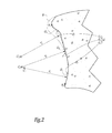
- This display is in particular made in a frontal plane to the patient, passing through the mapping points belonging to the glenoid surface G and located respectively the lowest and the highest, as illustrated by the figure 2 on which the two aforementioned mapping points are respectively referenced P 1 and P 2 .
- the degeneracy of the glenoid surface G is essentially located in the upper part of this surface, especially in the upper third of this surface.
- the glenoid surface before degeneration is indicated in phantom and pointed by the reference g: by comparison of the respective traces of the surfaces g and G in the plane of the figure 2 it can be seen that the surface G has undergone degeneration by wear much more pronounced in its upper part than in its lower part, which has remained almost intact.
- the surgeon commands the computer 2 to process the mapping data obtained during the first operating time.
- Computing means integrated in the computer 2 process either completely pre-established, or by integrating parameters chosen in a discretionary manner by the surgeon, the mapping data so as to distribute the mapping points of the glenoid surface G into three groups distinct, corresponding to respective portions G 1 , G 2 and G 3 of this surface G, which follow one another from bottom to top in a vertical direction.
- the three surface portions G 1 , G 2 and G 3 have an identical vertical dimension.
- the above-mentioned computer means then independently process each of the three groups of mapping data respectively associated with the surface portions G 1 , G 2 and G 3 , to model an imaginary sphere portion G ' 1 , G' 2 and G ' 3 , indicated in dashed line at figure 2 , which geometrically coincides globally with the corresponding surface portion G 1 , G 2 and G 3 .
- each sphere portion G ' 1 , G' 2 , G ' 3 are calculated by the above-mentioned computer means so that this sphere portion passes through the greatest number of mapped points for the corresponding surface portion G 1 , G 2 and G 3 , it being understood that each of these sphere portions is considered as passing through one of these mapped points when the multidirectional deviation between this portion of sphere and this point is zero or, at least, less than a predetermined value.
- Other mathematical methods for determining the geometrical characteristics of the sphere portions G ' 1 , G' 2 and G ' 3 may be employed in variants.
- the computer 2 displays on the screen 8, for the attention of the surgeon, all or part of the modeled sphere portions G ' 1 , G' 2 , G ' 3 , in particular their center C ' 1 , C' 2 , C ' 3 , simultaneously with the display of the mapping of the degenerative glenoid G as shown in FIG. figure 2 .
- a third step preferably provided that the surgeon validates the modeling results obtained so far and displayed on the screen 8, in particular that the modeled centers C ' 1 , and C' 2 are actually close to one of the other by comparison with the center C ' 3 , the computing means of the computer 2 construct, by calculation, a spherical theoretical glenoid surface G', which is centered on a center C 'and which has a radius r', of which, respectively, the position and the value are calculated from the positrons of the centers C ' 1 and C' 2 and from the values of the radii r ' 1 and r' 2 .
- an essential point of the invention consists, at this stage, in using the geometric data modeled for the region of the least degenerative glenoid surface G, that is to say the least worn, that is to say parts of the lower surface G 1 and intermediate G 2 .
- the theoretical glenoid surface G 'thus calculated corresponds to a reliable estimate of the entire glenoid surface before degeneration g. It will also be understood that, in practice, it is not possible to calculate the geometrical characteristics of the sphere portion G ' 3 if it is not necessary to display the latter on the screen 8 and to compare it with the sphere portions G' 1 and G ' 2 .
- the computer 2 determines the position of the point of intersection between this theoretical glenoid surface G 'and the radial line to this surface passing through the mapping point P 2 , that is to say the line passing through the points C 'and P 2 . As shown on the figure 3 , this point of intersection is referenced P up . It is understood that this point P up corresponds to a reliable estimate of the upper end point of the glenoid surface before degeneration g.
- the up point P is preferably displayed by the computer 2 on the screen 8 to the attention of the surgeon, for visual inspection.
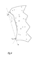
- the computer 2 provides the surgeon, by displaying it on the screen 8, a plan W of implantation of the glenoid component 5, the trace of which is visible to the figure 4 and which passes both by the aforementioned point P up and a point P down determined by the computer 2.
- this point P down corresponds to the mapped point P 1 .
- the implantation plan W corresponds to a preferential plan for implanting the glenoid component 5 in the sense that it provides the surgeon with a biomechanical behavior of the glenoid component 5 similar to, or similar to, the behavior of the glenoid surface before degeneration. g if the component 5 is put in place so that its axis 5B extends perpendicularly to this plane W.
- the computer 2 may for this purpose either use information directly provided by the surgeon or to orient in space the plane W passing through the points P up and P down using the angle of Lévigne, by integrating to the computer 2 a database relating to the definition of this angle, as provided by orthopedic literature.
- a glenoid component 12 of a shoulder prosthesis which, unlike component 5 of the figure 1 , is not a pre-existing piece, especially available in a range of homothetic implants.
- the component 12 comprises a solid implant body 14, in particular of metallic or synthetic nature, which has an overall cup shape.
- the body 14 On its side intended to cooperate by articulation with the humerus of a patient, bearing in particular a humeral prosthetic component of the shoulder prosthesis, the body 14 has a concave face 12A whose essential, indeed all, as here, defines an articular surface adapted to articulate against a substantially complementary surface, not shown in the figures, bounded either by the anatomical upper end of a humerus, or by the humeral component of the shoulder prosthesis.
- the implant body 14 On its opposite side, the implant body 14 has a face 12B which, when the component 12 is implanted, is supported directly or indirectly against the lateral bone end of a scapula, previously prepared for this purpose.
- the face 12B is advantageously provided with bone anchoring means in the scapula, for example in the form of a keel 16 as on the figure 5 .
- the glenoid component 12 was made "to measure” for the scapula S of the figure 1 .
- the articular surface 12A does not correspond to a pre-existing standard geometry, but reproduces the theoretical glenoid surface G 'supplied by the computer 2 during the third operation time mentioned above. Since this theoretical glenoid surface G 'is a reliable estimate of the glenoid surface before degeneration g, it is understood that the articular surface 12A is very close, from a geometric point of view, to this surface g, which explains the use of the expression "made to measure".
- the articular behavior of the glenoid component 12 at its face 12A is thus almost identical to the natural behavior of the patient's shoulder, before the degeneration of his scapula S.
- the bearing face 12B does not correspond either to a pre-existing standard geometry, but takes into account the state of degeneration of the glenoid surface G of the scapula S.
- the upper end portion of this face 12B is shaped to take into account the pronounced wear in the upper part of the glenoid surface G.
- the thickness of the implant body 14 that is to say its dimension in one direction mediolateral, is larger in its upper end portion of the body than in the rest of the body, the maximum value of this thickness at the high end portion of the body 14 being noted e on the figure 5 .
- the variation of the thickness of the implant body 14 is determined, for example using the computer 2, from the mapping data corresponding to the highest surface portion G 3 .
- the surgeon does not release, in the lower region of the glenoid surface G, here at the surface portions G 1 and G 2 , that a limited amount of bone material, just sufficient to account for the small thickness of the lower portion of the implant body 14, while that the upper part of this implant body is dimensioned in thickness to fit substantially to the surface portion G 3 .
- the surgeon does not try to "level" the glenoid surface G, during its preparation, on its most worn upper region, which would lead to excessively undermine healthy bone areas. scapula and medialize the glenoid component except to over-thicken the implant body.
- shaping of the material constituting the glenoid component 12 is performed by techniques known per se.
- a metal glenoid component the latter can be cast and then machined. If a plastic is used, it is usually poured and, if necessary, ground.
- the faces 12A and, advantageously, 12B are worked in a fine manner, to adjust them respectively to the theoretical glenoid surface G 'and to the previously prepared lateral end of the scapula S.
Abstract
Description
La présente invention concerne un procédé de modélisation d'une surface glénoïdienne d'une omoplate. Elle concerne également un dispositif chirurgical pour implanter un composant glénoïdien d'une prothèse d'épaule. Elle concerne en outre un procédé de fabrication d'un tel composant.The present invention relates to a method for modeling a glenoid surface of a scapula. It also relates to a surgical device for implanting a glenoid component of a shoulder prosthesis. It also relates to a method of manufacturing such a component.
Le remplacement de la surface articulaire glénoïdienne de l'omoplate d'un être humain par un composant prothétique glénoïdien concave d'une prothèse d'épaule est une opération chirurgicale délicate, notamment en raison de l'environnement ligamentaire de l'épaule. On constate que, selon la géométrie articulaire et/ou la position d'implantation d'un tel composant glénoïdien, des risques de décèlement du composant existent en raison de la modification des efforts appliqués à ce composant lors des mouvements ultérieurs de l'épaule prothésée.The replacement of the glenoid articular surface of the shoulder blade of a human with a concave glenoid prosthetic component of a shoulder prosthesis is a delicate surgical procedure, particularly because of the ligamentous environment of the shoulder. It can be seen that, depending on the articular geometry and / or the implantation position of such a glenoid component, there are risks of detection of the component due to the modification of the forces applied to this component during the subsequent movements of the prosthetic shoulder. .
Actuellement, les chirurgiens orthopédiques choisissent un tel composant glénoïdien parmi une gamme d'implants, présentant des géométries, notamment des tailles, légèrement différentes les unes des autres, puis estiment empiriquement la position d'implantation du composant glénoïdien choisi, en appréciant visuellement la géométrie de la surface glénoïdienne du patient opéré : le chirurgien essaie de choisir et d'implanter le composant prothétique sur l'omoplate de manière à ce que ce composant reproduise la surface articulaire glénoïdienne d'origine du patient. Toutefois, cette méthode est imprécise et, surtout, très peu satisfaisante lorsque la glène d'origine du patient est trop dégénérative pour fournir une indication directement exploitable par l'observation chirurgicale.Currently, orthopedic surgeons choose such a glenoid component from a range of implants, having geometries, notably sizes, slightly different from each other, then empirically estimate the implantation position of the selected glenoid component, by visually appreciating the geometry of the glenoid surface of the operated patient: the surgeon tries to choose and implant the prosthetic component on the scapula so that this component reproduces the original glenoid articular surface of the patient. However, this method is imprecise and, above all, very unsatisfactory when the original glenoid of the patient is too degenerative to provide an indication directly exploitable by the surgical observation.
Dans le domaine de la chirurgie orthopédique de la hanche,
Le but de la présente invention est de proposer un procédé de modélisation d'une surface glénoïdienne d'une omoplate, en vue d'aider le chirurgien à optimiser la position d'implantation d'un composant glénoïdien et/ou en vue de fabriquer un composant glénoïdien davantage adapté à une omoplate à prothéser, notamment en présence d'une glène opérée dans un état de dégénérescence avancée.The aim of the present invention is to propose a method for modeling a glenoid surface of a scapula, in order to help the surgeon optimize the implantation position of a glenoid component and / or to produce a glenoid surface. glenoid component more suitable for a scapula to prosthesis, especially in the presence of a glenoid operated in a state of advanced degeneration.
A cet effet, l'invention a pour objet un procédé de modélisation d'une surface glénoïdienne d'une omoplate, tel que défini à la revendication 1.To this end, the subject of the invention is a method for modeling a glenoid surface of a scapula, as defined in claim 1.
L'idée à la base de l'invention est liée au constat selon lequel, dans la très grande majorité des cas chirurgicaux, la dégénérescence de la glène d'un patient est située exclusivement dans la partie haute et postérieure de la surface glénoïdienne. Dans ces conditions, l'invention se propose d'utiliser exclusivement une partie située le plus bas de la surface glénoïdienne dégénérative, pour obtenir par modélisation une surface glénoïdienne théorique aussi proche que possible de la surface glénoïdienne avant dégénérescence, à l'aide d'au moins une portion d'ellipsoïde imaginaire judicieusement calculée, comme défini ci-dessus. En pratique, la méthode de modélisation conforme à l'invention est mise en oeuvre par des moyens ad hoc, en particulier informatiques.The idea underlying the invention is related to the finding that, in the vast majority of surgical cases, the degeneration of the glenoid of a patient is located exclusively in the upper and posterior portion of the glenoid surface. Under these conditions, the invention proposes to exclusively use a portion located the lowest of the degenerative glenoid surface, to obtain by modeling a theoretical glenoid surface as close as possible to the glenoid surface before degeneration, with the aid of at least one judiciously calculated imaginary ellipsoid portion, as defined above. In practice, the modeling method according to the invention is implemented by means ad hoc, in particular computer.
Le fait d'estimer par modélisation cette surface glénoïdienne théorique présente des intérêts remarquables, à la fois et de manière indépendante, pour optimiser la position d'implantation d'un composant glénoïdien pré-existant et pour fabriquer un composant glénoïdien spécifiquement adapté à l'omoplate du patient, comme exposé ci-après plus en détail. Ainsi, l'invention a également pour objets un dispositif chirurgical et une méthode chirurgicale d'implantation d'un composant glénoïdien d'une prothèse d'épaule, ainsi qu'un procédé de fabrication d'un composant glénoïdien pour une omoplate, tels que définis plus bas.Modeling this theoretical glenoid surface presents remarkable and independent interests in optimizing the implantation position of a pre-existing glenoid component and in producing a glenoid component specifically adapted to the glenoid surface. scapula of the patient, as discussed below in more detail. Thus, the invention also relates to a surgical device and a surgical method for implanting a glenoid component of a shoulder prosthesis, and a method of manufacturing a glenoid component for a scapula, such as defined below.
D'autres caractéristiques du procédé de modélisation conforme à l'invention, précisant des aspects avantageux de ce procédé, prises isolément ou selon toutes les combinaisons techniquement possibles, sont spécifiées aux revendications dépendantes 2 à 6.Other features of the modeling method according to the invention, specifying advantageous aspects of this method, taken individually or in any technically possible combination, are specified in the
Comme annoncé plus haut, l'invention a en outre pour objet un dispositif chirurgical d'implantation d'un composant glénoïdien d'une prothèse d'épaule, tel que défini à la revendication 7.As announced above, the invention further relates to a surgical device for implanting a glenoid component of a shoulder prosthesis, as defined in claim 7.
Ainsi, grâce, d'une part, à la surface glénoïdienne théorique fournie par le procédé de modélisation défini plus haut et, d'autre part, à une information relative à un point de référence bas, que le chirurgien peut obtenir directement de l'extrémité inférieure en principe non altérée de la surface glénoïdienne dégénérative du patient, le chirurgien peut baser ses gestes d'implantation d'un composant glénoïdien sur des données satisfaisantes en ce qui concerne la géométrie de la surface glénoïdienne avant dégénérescence du patient opéré. Le chirurgien est ainsi en mesure d'améliorer la configuration d'implantation de ce composant glénoïdien, et ce au cours de l'intervention chirurgicale.Thus, thanks, on the one hand, to the theoretical glenoid surface provided by the modeling method defined above and, on the other hand, to information relating to a low reference point, which the surgeon can obtain directly from the lower end in principle unaltered degenerative glenoid surface of the patient, the surgeon can base his gestures of implantation of a glenoid component on satisfactory data with respect to the geometry of the glenoid surface before degeneration of the patient operated. The surgeon is thus able to improve the implantation configuration of this glenoid component, and this during the surgical procedure.
Des caractéristiques avantageuses, précisant la mise en oeuvre du dispositif conforme à l'invention, prises isolément ou selon toutes les combinaisons techniquement possibles, sont spécifiées aux revendications dépendantes 8 à 11.Advantageous features, specifying the implementation of the device according to the invention, taken individually or in any technically possible combination, are specified in the
On définit également ici une méthode chirurgicale d'implantation d'un composant glénoïdien d'une prothèse d'épaule, dans laquelle :
- on repère dans l'espace l'omoplate d'un patient opéré,
- on cartographie la surface glénoïdienne de cette omoplate, en utilisant des données acquises par palpation de l'omoplate et/ou des données extraites d'images pré-opératoires et/ou de données fournies par une base de données préétablies,
- on modélise la surface glénoïdienne conformément au procédé de modélisation défini plus haut, de sorte que, à partir des données de cartographie, on obtient une surface glénoïdienne théorique de l'omoplate du patient opéré,
- on détermine la position dans l'espace d'un point de référence bas pour implanter le composant glénoïdien, à partir des données liées à la cartographie de l'extrémité inférieure de la surface glénoïdienne, et
- on implante le composant glénoïdien dans une configuration spatiale déterminée au moins à partir de la surface glénoïdienne théorique et du point de référence bas.
- we find in space the scapula of an operated patient,
- the glenoid surface of this scapula is mapped, using data acquired by palpation of the scapula and / or data extracted from pre-operative images and / or data provided by a pre-established database,
- the glenoid surface is modeled according to the modeling method defined above, so that, from the mapping data, a theoretical glenoid surface of the scapula of the operated patient is obtained,
- determining the position in space of a low reference point to implant the glenoid component, from the data related to the mapping of the lower end of the glenoid surface, and
- the glenoid component is implanted in a determined spatial configuration at least from the theoretical glenoid surface and the low reference point.
Cette méthode chirurgicale peut être mise en oeuvre par le dispositif d'implantation tel que défini plus haut.This surgical method can be implemented by the implantation device as defined above.
Par ailleurs, cette méthode présente avantageusement des aspects additionnnels qui correspondent respectivement à la mise en oeuvre pratique des caractéristiques additionnelles avantageuses listées ci-dessus pour le dispositif d'implantation.Moreover, this method advantageously has additional aspects which correspond respectively to the practical implementation of the additional advantageous features listed above for the implant device.
Comme annoncé plus haut, l'invention a en outre pour objet un procédé de fabrication d'un composant glénoïdien d'une prothèse d'épaule pour une omoplate, tel que défini à la revendication 12.As announced above, the invention further relates to a method of manufacturing a glenoid component of a shoulder prosthesis for a scapula, as defined in
Le procédé de fabrication conforme à l'invention permet, en quelque sorte, d'obtenir un implant glénoïdien « sur mesure », dans le sens où sa face articulaire reproduit aussi fidèlement que possible la surface glénoïdienne, avant sa dégénérescence, de l'omoplate à prothéser. Le confort articulaire pour le patient est alors remarquable.The manufacturing method according to the invention makes it possible, so to speak, to obtain a "tailor-made" glenoid implant, in the sense that its articular surface reproduces as closely as possible the glenoid surface, before its degeneration, of the shoulder blade. to prosthesis. The articular comfort for the patient is then remarkable.
Bien entendu, pour une même omoplate traitée, il est avantageusement possible de fabriquer un composant glénoïdien « sur mesure », grâce au procédé de fabrication conforme à l'invention, puis d'implanter ce composant glénoïdien à l'aide du dispositif d'implantation défini plus haut, c'est-à-dire conformément à la méthode d'implantation également définie plus haut.Of course, for the same scapula treated, it is advantageously possible to manufacture a "tailor-made" glenoid component, by means of the manufacturing method according to the invention, then to implant this glenoid component using the implantation device. defined above, that is to say according to the implantation method also defined above.
Un aspect complémentaire avantageux du procédé de fabrication conforme à l'invention est spécifié à la revendication dépendante 13.An advantageous additional aspect of the manufacturing method according to the invention is specified in the dependent claim 13.
L'invention sera mieux comprise à la lecture de la description qui va suivre, donné uniquement à titre d'exemple et faite en se référant aux dessins sur lesquels :
- la
figure 1 est une vue schématique d'un dispositif d'implantation selon l'invention, appliqué à l'omoplate d'un patient à opérer en vue d'y implanter un composant glénoïdien ; - les
figures 2 à 4 sont des sections schématiques, dans un plan frontal au patient, de l'omoplate en cours d'opération à l'aide du dispositif de lafigure 1 ; et - la
figue 5 est une vue schématique en élévation d'un composant glénoïdien fabriqué conformément au procédé de fabrication selon l'invention.
- the
figure 1 is a schematic view of an implantation device according to the invention, applied to the scapula of a patient to operate in order to implant a glenoid component; - the
Figures 2 to 4 are schematic sections, in a frontal plane to the patient, of the scapula during operation using the device of thefigure 1 ; and - Fig. 5 is a schematic elevational view of a glenoid component manufactured according to the manufacturing method of the invention.
Le dispositif chirurgical 1 de la
L'omoplate S est associée, entre autres, à des tendons et ligaments et délimite, sur son côté latéral, une surface glénoïdienne G. Cette surface glénoïdienne G est dégénérative, c'est-à-dire qu'elle est partiellement endommagée par usure en raison de l'âge avancé et/ou d'une pathologie du patient opéré. Comme expliqué ci-après en détail, le dispositif 1 est adapté pour aider un chirurgien à implanter, en remplacement de la surface glénoïdienne dégénérative G, un composant prothétique glénoïdien 5, connu en soi. Dans l'exemple considéré ici, ce composant glénoïdien 5 présente une forme globale de cupule et délimite une face articulaire 5A de géométrie sensiblement sphérique, définissant un axe de révolution 5B.The scapula S is associated, among others, with tendons and ligaments and delimits, on its lateral side, a glenoid surface G. This glenoid surface G is degenerative, that is to say that it is partially damaged by wear because of the advanced age and / or pathology of the operated patient. As explained below in detail, the device 1 is adapted to assist a surgeon to implant, replacing the degenerative glenoid surface G, a
Le composant prothétique 5 décrit juste ci-dessus n'est donné qu'à titre d'exemple et d'autres composants glénoïdiens prothétiques, de géométries et/ou de natures différentes, peuvent être implantés au moyen du dispositif 1, suivant la méthode chirurgicale d'implantation décrite plus loin.The
Pour permettre à l'ordinateur 2 de repérer dans l'espace l'os de l'omoplate S, le dispositif 1 comporte un groupe de marqueurs 6 qui renvoient, de façon passive, le rayonnement infrarouge en direction du capteur 3. Ce groupe de marqueurs 6 forme un système de marquage tridimensionnelle permettant à l'ensemble ordinateur 2 - capteur 3 de suivre dans l'espace la position et le déplacement de l'omoplate. L'utilisation de tels marqueurs est bien connue dans le domaine de l'orthopédie assistée par ordinateur, par exemple par le document
L'ordinateur 2 est également associé à un écran vidéo 8 à même d'afficher des informations utiles au chirurgien, notamment les informations relatives au repérage de l'omoplate S et d'autres données décrites plus loin, de préférence sous forme de représentations graphiques comme détaillé ci-après. Le dispositif 1 comporte également des moyens de commande 9, par exemple sous forme d'une pédale actionnable par le pied du chirurgien.The
Le dispositif chirurgical 1 comporte en outre d'autres composants qui vont être détaillés ci-après lors de la description d'un exemple détaillé d'utilisation de ce dispositif en vue de l'implantation du composant glénoïdien 5. Par convention dans tout le présent document, les termes de positionnement dans l'espace, tels que les termes « haut », « bas », « vertical », « horizontal », etc., s'entendent dans leur sens anatomique, c'est-à-dire par rapport au patient opéré considéré comme se tenant debout sur une surface plane.The surgical device 1 further comprises other components which will be detailed below when describing a detailed example of use of this device for the implantation of the
Dans un premier temps, le chirurgien incise les parties molles de l'épaule du patient et recueille un certain nombre de données relatives, entre autres, à la géométrie anatomique de l'os de l'omoplate S du patient. A cet effet, différents moyens d'acquisition de ces données sont envisageables. A titre d'exemple, le chirurgien utilise un palpeur 10 repéré par l'ensemble ordinateur 2 - capteur 3 et préalablement étalonné. Ce palpeur est amené sur des lieux remarquables de l'omoplate, notamment sur toute la surface glénoïdienne G, et, par actionnement de la pédale de commande 9, le chirurgien fait enregistrer à l'ordinateur 2 la position du palpeur 10. A partir de ces données et, le cas échéant, de données préenregistrées relatives à une géométrie de base de l'omoplate d'un être humain, l'ordinateur 2 est capable de dresser une cartographie tridimensionnelle de la surface glénoïdienne dégénérative G de cette omoplate.Firstly, the surgeon incises the soft tissues of the patient's shoulder and collects a certain amount of data relating, among other things, to the anatomical geometry of the bone of the scapula S of the patient. For this purpose, different means of acquisition of these data are possible. For example, the surgeon uses a
A titre de variante des différentes possibilités pour acquérir les données de cartographie relatives à la géométrie anatomique de la surface glénoïdienne G, on peut envisager d'extraire de telles données depuis des images pré-opératoires de l'omoplate S du patient, par exemple des images de scanner. De telles données peuvent d'ailleurs être combinées à des données obtenues par palpation comme ci-dessus, en les associant éventuellement à des données prédéterminées fournies par des bases de données disponibles dans le domaine de la chirurgie de l'épaule.As a variant of the different possibilities for acquiring the mapping data relating to the anatomical geometry of the glenoid surface G, it is possible to envisage extracting such data from pre-operative images of the scapula S of the patient, for example scanner images. Such data can moreover be combined with data obtained by palpation as above, possibly associating them with predetermined data provided by databases available in the field of shoulder surgery.
A la fin de ce premier temps, l'ordinateur 2 affiche sur l'écran 8 la cartographie réalisée, notamment à des fins de contrôle visuel par le chirurgien. Cet affichage est en particulier réalisé dans un plan frontal au patient, passant par les points de cartographie appartenant à la surface glénoïdienne G et respectivement situés le plus bas et le plus haut, comme illustré par la
La
Dans un deuxième temps, le chirurgien commande l'ordinateur 2 pour qu'il traite les données de cartographie obtenues lors du premier temps opératoire. Des moyens informatiques intégrés à l'ordinateur 2 traitent, soit de manière complètement préétablie, soit en intégrant des paramètres choisis de manière discrétionnaire par le chirurgien, les données de cartographie de manière à répartir les points de cartographie de la surface glénoïdienne G en trois groupes distincts, correspondant à des parties respectives G1, G2 et G3 de cette surface G, qui se succèdent de bas en haut suivant une direction verticale.In a second step, the surgeon commands the
Par exemple, les trois parties de surface G1, G2 et G3 présentent une dimension verticale identique.For example, the three surface portions G 1 , G 2 and G 3 have an identical vertical dimension.
Les moyens informatiques précités traitent ensuite, de manière indépendante, chacun des trois groupes de données de cartographie respectivement associés aux parties de surface G1, G2 et G3, pour modéliser une portion de sphère imaginaire G'1, G'2 et G'3, indiquée en pointillés à la
Avantageusement, l'ordinateur 2 affiche sur l'écran 8, à l'attention du chirurgien, tout ou partie des portions de sphère modélisées G'1, G'2, G'3, en particulier leur centre C'1, C'2, C'3 , simultanément à l'affichage de la cartographie de la glène dégénérative G comme montré sur la
Sur cette
Dans un troisième temps, de préférence sous réserve que le chirurgien valide les résultats de modélisation obtenus jusqu'ici et affichés sur l'écran 8, en particulier que les centres modélisés C'1,et C'2 sont effectivement proches l'un de l'autre par comparaison au centre C'3, les moyens informatiques de l'ordinateur 2 construisent, par calcul, une surface glénoïdienne théorique sphérique G', qui est centré sur un centre C' et qui présente un rayon r', dont, respectivement, la position et la valeur sont calculées à partir des positons des centres C'1 et C'2 et à partir des valeurs des rayons r'1 et r'2. A titre d'exemple, comme illustré à la
L'ordinateur 2 détermine alors ensuite la position du point d'intersection entre cette surface glénoïdienne théorique G' et la droite radiale à cette surface passant par le point de cartographie P2, c'est-à-dire la droite passant par les points C' et P2. Comme représenté sur la
Dans un quatrième temps, l'ordinateur 2 fournit au chirurgien, en l'affichant sur l'écran 8, un plan W d'implantation du composant glénoïdien 5, dont la trace est visible à la
L'important est que le plan d'implantation W correspond à un plan préférentiel pour implanter le composant glénoïdien 5 dans le sens où il assure au chirurgien un comportement biomécanique du composant glénoïdien 5 proche, voire analogue, au comportement de la surface glénoïdienne avant dégénérescence g si le composant 5 est mis en place de telle sorte que son axe 5B s'étende perpendiculairement à ce plan W.The important thing is that the implantation plan W corresponds to a preferential plan for implanting the
Dans la mesure où le recours aux deux seuls points précités Pup et Pdown est insuffisant pour fournir toutes les caractéristiques spatiales du plan d'implantation W, l'ordinateur 2 peut à cette fin soit utiliser des renseignements directement fournis par le chirurgien, soit orienter dans l'espace le plan W passant par les points Pup et Pdown à l'aide de l'angle de Lévigne, en intégrant à l'ordinateur 2 une base de données relatives à la définition de cet angle, telles que fournies par la littérature orthopédique.Since the only two points mentioned above P up and P down are insufficient to provide all the spatial characteristics of the layout plan W, the
Sur la
Sur son côté destiné à coopérer par articulation avec l'humérus d'un patient, portant notamment un composant prothétique huméral de la prothèse d'épaule, le corps 14 présente une face concave 12A dont l'essentiel, voire la totalité comme ici, définit une surface articulaire adaptée pour s'articuler contre une surface sensiblement complémentaire, non représentée sur les figures, délimitée soit par l'extrémité supérieure anatomique d'un humérus, soit par le composant huméral de la prothèse d'épaule.On its side intended to cooperate by articulation with the humerus of a patient, bearing in particular a humeral prosthetic component of the shoulder prosthesis, the
Sur son côté opposé, le corps d'implant 14 présente une face 12B qui, lorsque le composant 12 est implanté, est appuyé directement ou indirectement contre l'extrémité latérale osseuse d'une omoplate, préalablement préparée à cette fin. De manière connue en soi, la face 12B est avantageusement munie de moyens d'ancrage osseux dans l'omoplate, par exemple sous la forme d'une quille 16 comme sur la
Le composant glénoïdien 12 a été fabriqué « sur mesure » pour l'omoplate S de la
Avantageusement, la face d'appui 12B ne correspond pas non plus à une géométrie standard pré-existante, mais tient compte de l'état de dégénérescence de la surface glénoïdienne G de l'omoplate S. En particulier, la partie d'extrémité supérieure de cette face 12B est conformée pour tenir compte de l'usure prononcée dans la partie haute de la surface glénoïdienne G. Pour ce faire, l'épaisseur du corps d'implant 14, c'est-à-dire sa dimension suivant une direction médio-latérale, est plus grande dans sa partie d'extrémité supérieure du corps que dans le reste du corps, la valeur maximale de cette épaisseur au niveau de la partie d'extrémité haute du corps 14 étant noté e sur la
En pratique, la mise en forme de la matière constituant le composant glénoïdien 12 est réalisée par des techniques connues en soi. Dans le cas d'un composant glénoïdien métallique, ce dernier peut être coulé puis usiné. Si une matière plastique est utilisée, elle est généralement coulée puis, le cas échéant, rectifiée. Dans tous les cas, les faces 12A et, avantageusement, 12B sont travaillées de manière fine, pour les ajuster respectivement à la surface glénoïdienne théorique G' et à l'extrémité latérale préalablement préparée de l'omoplate S.In practice, shaping of the material constituting the
Divers aménagements et variantes au dispositif d'implantation 1, à la méthode d'implantation et à la méthode de fabrication du composant 12, décrits ci-dessus sont par ailleurs envisageables. A titre d'exemples :
- les moyens de repérage de l'os de l'omoplate S et/ou du palpeur 10 ne sont pas limités à des marqueurs réfléchissant l'infrarouge ; des marqueurs sensibles aux ultrasons ou à des champs électromagnétiques sont par exemple utilisables ;
- la nature géométrique des portions de sphères imaginaires G'1, G'2 et G'3 peut être généralisée à celle de portions d'ellipsoïde, notamment afin de modéliser ces portions de surface au plus près des parties correspondantes G1, G2 et G3 de la surface glénoïdienne G ; d'ailleurs, notamment dans ce cas, il est possible de ne prévoir la modélisation que d'une seule portion d'ellipsoïde, qui coïncide sensiblement avec une partie la plus basse de la surface glénoïdienne G et qui constituera alors, aux fins de la méthode, la surface glénoïdienne théorique G' ;
- le fait de déterminer le plan d'implantation W peut être rendu optionnel lorsque l'ordinateur 2 est à même de guider dans l'espace un outil d'implantation du composant glénoïdien 5 en vue que la
surface articulaire 5A de ce composant soit positionnée en coïncidence avec la surface glénoïdienne théorique G', en tenant compte du point de référence bas Pdown ; - l'étendue verticale de l'unique partie de surface de glène la plus basse ou celle de chacune des différentes parties de surface de glène se succédant de bas en haut peut être pré-établie, choisie arbitrairement par le chirurgien en l'indiquant à l'ordinateur 2, ou bien calculée par l'ordinateur, notamment par une formule de rapport entre l'étendue de la partie considérée et l'étendue totale de la glène G ; et/ou
- davantage que trois portions de sphère, voire d'ellipsoïde, imaginaires peuvent être modélisées à partir d'autant de parties de surface successives, suivant la verticale, de la surface glénoïdienne dégénérative G, du moment que la surface glénoïdienne théorique sphérique G', permettant de déterminer la position dans l'espace du point de référence haut Pup, est calculée à partir d'uniquement le ou des groupes de données de cartographie correspondant respectivement à la partie de surface la plus basse ou à des parties de surfaces situées le plus bas.
- the means for locating the bone of the scapula S and / or the
probe 10 are not limited to infrared-reflecting markers; markers sensitive to ultrasound or to electromagnetic fields are for example usable; - the geometrical nature of the portions of imaginary spheres G ' 1 , G' 2 and G ' 3 can be generalized to that of ellipsoid portions, especially in order to model these surface portions as close as possible to the corresponding parts G 1 , G 2 and G 3 of the glenoid surface G; Moreover, especially in this case, it is possible to provide for modeling only a single portion of ellipsoid, which substantially coincides with a lower part of the glenoid surface G and which will then constitute, for the purposes of the method, the theoretical glenoid surface G ';
- the fact of determining the implantation plan W can be made optional when the
computer 2 is able to guide in space a tool for implanting theglenoid component 5 so that thearticular surface 5A of this component is positioned in coincidence with the theoretical glenoid surface G ', taking into account the low reference point P down ; - the vertical extent of the single lowest glenoid surface area or that of each of the different glenoid surface portions succeeding each other from below upwards may be pre-established, arbitrarily selected by the surgeon by indicating to the
computer 2, or calculated by the computer, in particular by a ratio formula between the extent of the part under consideration and the total extent of the glenoid G; and or - more than three imaginary spherical or even ellipsoid portions can be modeled from as many successive surface portions, along the vertical, of the degenerative glenoid surface G, as long as the spherical theoretical glenoid surface G ', allowing determine the position in the space of the high reference point P up, is calculated from only the group or groups of mapping data respectively corresponding to the lowest surface part or to parts of surfaces located the most low.
Claims (13)
et en ce qu'on détermine par calcul, à partir du ou des autre(s) groupe(s) de données de cartographie, respectivement une ou plusieurs portion(s) d'ellipsoïde imaginaire (G'2, G'3) autre que la première portion d'ellipsoïde (G'1), cette ou ces autres portion(s) d'ellipsoïde coïncidant sensiblement avec respectivement la ou les autres partie(s) de surface correspondante(s) (G2, G3),
et en ce qu'on fournit la surface glénoïdienne théorique (G') à partir de la première portion d'ellipsoïde (G'1) et de l'autre ou d'au moins une (G'2) des autres portion(s) d'ellipsoïde.Method according to Claim 1, characterized in that , among the mapping data, one or more groups of mapping data other than the first group of mapping data, respectively corresponding to as many parts of the map, are distinguished. surface (G 2 , G 3 ) of the glenoid surface (G), distinct from the first surface portion (G 1 ) and disposed in the vertical direction associated with the scapula, in succession to this first part of surface and, where appropriate, to each other,
and in that one or more imaginary ellipsoid portions (G ' 2 , G' 3 ) are determined by calculation from the other group (s) of mapping data, respectively that the first portion of ellipsoid (G ' 1 ), this or these other portion (s) of ellipsoid coinciding substantially with respectively the other part (s) corresponding surface (s) (G 2 , G 3 ),
and in that the theoretical glenoid surface (G ') is provided from the first portion of the ellipsoid (G' 1 ) and from the other or at least one (G ' 2 ) of the other portion (s). ) of ellipsoid.
et en ce que les moyens d'implantation (2) sont adaptés pour fournir la position dans l'espace d'un plan (W) d'implantation du composant glénoïdien (5 ; 12), qui passe par les points de référence haut (Pep) et bas (Pdown).Device according to one of claims 7 or 8, characterized in that it further comprises second determining means (2) for determining the position in space of a high reference point (P ep ) for implanting the glenoid component (5; 12), from, on the one hand, mapping data obtained exclusively at the upper end of the glenoid surface (G) by the mapping means (2, 10) and, on the other hand, of the theoretical glenoid surface (G '),
and in that the implanting means (2) are adapted to provide the position in the space of an implantation plane (W) of the glenoid component (5; 12), which passes through the high reference points ( P ep ) and low (P down ).
dans lequel on conforme la face articulaire (12A) d'un corps d'implant (14), destinée à s'articuler contre une surface humérale sensiblement complémentaire, de manière qu'au moins une partie de cette face articulaire reproduise la surface glénoïdienne théorique (G') fournie par le procédé de modélisation.A method of manufacturing a glenoid component (12) of a shoulder prosthesis (10) for a scapula (S), wherein the surface is modeled glenoid (G) of the scapula according to the modeling method according to any one of claims 1 to 6, and
in which the articular surface (12A) of an implant body (14) is designed to articulate against a substantially complementary humeral surface, so that at least a part of this articular surface reproduces the theoretical glenoid surface. (G ') provided by the modeling method.
Applications Claiming Priority (1)
| Application Number | Priority Date | Filing Date | Title |
|---|---|---|---|
| FR0854092A FR2932674B1 (en) | 2008-06-20 | 2008-06-20 | METHOD FOR MODELING A GLENOIDAL SURFACE OF AN OMOPLATE, DEVICE FOR IMPLANTING A GLENOIDAL COMPONENT OF A SHOULDER PROSTHESIS, AND METHOD FOR MANUFACTURING SUCH COMPOUND |
Publications (2)
| Publication Number | Publication Date |
|---|---|
| EP2135576A1 true EP2135576A1 (en) | 2009-12-23 |
| EP2135576B1 EP2135576B1 (en) | 2015-09-02 |
Family
ID=40263315
Family Applications (1)
| Application Number | Title | Priority Date | Filing Date |
|---|---|---|---|
| EP09163299.2A Active EP2135576B1 (en) | 2008-06-20 | 2009-06-19 | Method for modelling a glenoidal surface of a scapula, device for implanting a glenoidal component of a shoulder prosthesis, and method for manufacturing such a component |
Country Status (3)
| Country | Link |
|---|---|
| US (4) | US8932361B2 (en) |
| EP (1) | EP2135576B1 (en) |
| FR (1) | FR2932674B1 (en) |
Cited By (6)
| Publication number | Priority date | Publication date | Assignee | Title |
|---|---|---|---|---|
| EP2324801A1 (en) * | 2009-11-24 | 2011-05-25 | Tornier | Device and method for determining a configuration for implanting a glenoid prosthetic component or a configuration for applying a glenoid resurfacing tool |
| US10405993B2 (en) | 2013-11-13 | 2019-09-10 | Tornier Sas | Shoulder patient specific instrument |
| US10716676B2 (en) | 2008-06-20 | 2020-07-21 | Tornier Sas | Method for modeling a glenoid surface of a scapula, apparatus for implanting a glenoid component of a shoulder prosthesis, and method for producing such a component |
| US10959742B2 (en) | 2017-07-11 | 2021-03-30 | Tornier, Inc. | Patient specific humeral cutting guides |
| US11065016B2 (en) | 2015-12-16 | 2021-07-20 | Howmedica Osteonics Corp. | Patient specific instruments and methods for joint prosthesis |
| US11166733B2 (en) | 2017-07-11 | 2021-11-09 | Howmedica Osteonics Corp. | Guides and instruments for improving accuracy of glenoid implant placement |
Families Citing this family (9)
| Publication number | Priority date | Publication date | Assignee | Title |
|---|---|---|---|---|
| WO2012021241A2 (en) | 2010-08-12 | 2012-02-16 | Smith & Nephew, Inc. | Methods and devices for installing standard and reverse shoulder implants |
| US20120276509A1 (en) * | 2010-10-29 | 2012-11-01 | The Cleveland Clinic Foundation | System of preoperative planning and provision of patient-specific surgical aids |
| WO2015068035A1 (en) * | 2013-11-08 | 2015-05-14 | Imascap | Methods, systems and devices for pre-operatively planned adaptive glenoid implants |
| US10433969B2 (en) | 2013-12-30 | 2019-10-08 | United Orthopedic Corp. | Arthroplasty implants and methods for orienting joint prosthesis |
| US9962266B2 (en) | 2015-09-11 | 2018-05-08 | Deltoid, Llc | Arthroplasty components |
| US10575968B2 (en) | 2014-05-16 | 2020-03-03 | Howmedica Osteonics Corp. | Guides for fracture system |
| US9681960B2 (en) | 2014-05-16 | 2017-06-20 | Howmedica Osteonics Corp. | Guides for fracture system |
| USD835276S1 (en) | 2015-09-11 | 2018-12-04 | United Orthopedic Corporation | Keeled glenoid |
| WO2019245867A1 (en) | 2018-06-19 | 2019-12-26 | Tornier, Inc. | Virtual guidance for orthopedic surgical procedures |
Citations (7)
| Publication number | Priority date | Publication date | Assignee | Title |
|---|---|---|---|---|
| FR2579454A1 (en) * | 1985-03-28 | 1986-10-03 | Rambert Andre | Glenohumeral prosthesis |
| WO2002061688A2 (en) * | 2001-01-29 | 2002-08-08 | The Acrobot Company Limited | Modelling for surgery |
| EP1249213A2 (en) | 1997-03-11 | 2002-10-16 | Aesculap AG & Co. KG | Method and device for pre-operative determination of the positional data of endoprosthetic parts |
| FR2859099A1 (en) * | 2003-08-25 | 2005-03-04 | Tornier Sa | GLENOIDAL COMPONENT OF SHOULDER PROSTHESIS AND TOTAL SHOULDER PROSTHESIS INCORPORATING SUCH COMPONENT |
| US20050065628A1 (en) * | 2003-09-18 | 2005-03-24 | Jeffrey Roose | Customized prosthesis and method of designing and manufacturing a customized prosthesis by utilizing computed tomography data |
| EP1563810A1 (en) | 2004-02-10 | 2005-08-17 | Tornier | Surgical apparatus for implanting a total hip prosthesis |
| EP1862151A1 (en) * | 2006-05-31 | 2007-12-05 | BrainLAB AG | Method for selection of an femoral implant |
Family Cites Families (248)
| Publication number | Priority date | Publication date | Assignee | Title |
|---|---|---|---|---|
| US4919670A (en) | 1988-02-03 | 1990-04-24 | Intermedics Orthopedics, Inc. | Modular humeral prosthesis |
| US5204055A (en) | 1989-12-08 | 1993-04-20 | Massachusetts Institute Of Technology | Three-dimensional printing techniques |
| US5030219A (en) | 1990-01-22 | 1991-07-09 | Boehringer Mannheim Corporation | Glenoid component installation tools |
| US5329846A (en) | 1991-08-12 | 1994-07-19 | Bonutti Peter M | Tissue press and system |
| DE4219939C2 (en) | 1992-06-18 | 1995-10-19 | Klaus Dipl Ing Radermacher | Device for aligning, positioning and guiding machining tools, machining or measuring devices for machining a bony structure and method for producing this device |
| US5370693A (en) | 1992-09-28 | 1994-12-06 | Depuy Inc. | Orthopedic implant augmentation and stabilization device |
| US5383938A (en) | 1993-02-12 | 1995-01-24 | Zimmer, Inc. | Locking ring for an acetabular cup |
| BE1008372A3 (en) | 1994-04-19 | 1996-04-02 | Materialise Nv | METHOD FOR MANUFACTURING A perfected MEDICAL MODEL BASED ON DIGITAL IMAGE INFORMATION OF A BODY. |
| US5458637A (en) | 1994-11-21 | 1995-10-17 | Zimmer, Inc. | Orthopaedic base component with modular augmentation block |
| US5610966A (en) | 1995-02-15 | 1997-03-11 | Argonne National Laboratories/University Of Chicago Development Corp. | Method and device for linear wear analysis |
| US5725586A (en) | 1995-09-29 | 1998-03-10 | Johnson & Johnson Professional, Inc. | Hollow bone prosthesis with tailored flexibility |
| US5824078A (en) | 1996-03-11 | 1998-10-20 | The Board Of Trustees Of The University Of Arkansas | Composite allograft, press, and methods |
| US6652260B2 (en) | 1996-03-11 | 2003-11-25 | The Board Of Trustees Of The University Of Arkansas | Composite allograft press |
| US5779710A (en) | 1996-06-21 | 1998-07-14 | Matsen, Iii; Frederick A. | Joint replacement method and apparatus |
| US5769856A (en) | 1996-06-24 | 1998-06-23 | Osteonics Corp. | Drill guide and implant method |
| US6126690A (en) | 1996-07-03 | 2000-10-03 | The Trustees Of Columbia University In The City Of New York | Anatomically correct prosthesis and method and apparatus for manufacturing prosthesis |
| US5824085A (en) | 1996-09-30 | 1998-10-20 | Integrated Surgical Systems, Inc. | System and method for cavity generation for surgical planning and initial placement of a bone prosthesis |
| US8882847B2 (en) | 2001-05-25 | 2014-11-11 | Conformis, Inc. | Patient selectable knee joint arthroplasty devices |
| US20090222103A1 (en) | 2001-05-25 | 2009-09-03 | Conformis, Inc. | Articular Implants Providing Lower Adjacent Cartilage Wear |
| US7468075B2 (en) | 2001-05-25 | 2008-12-23 | Conformis, Inc. | Methods and compositions for articular repair |
| US8234097B2 (en) | 2001-05-25 | 2012-07-31 | Conformis, Inc. | Automated systems for manufacturing patient-specific orthopedic implants and instrumentation |
| US8617242B2 (en) | 2001-05-25 | 2013-12-31 | Conformis, Inc. | Implant device and method for manufacture |
| US7618451B2 (en) | 2001-05-25 | 2009-11-17 | Conformis, Inc. | Patient selectable joint arthroplasty devices and surgical tools facilitating increased accuracy, speed and simplicity in performing total and partial joint arthroplasty |
| US7534263B2 (en) | 2001-05-25 | 2009-05-19 | Conformis, Inc. | Surgical tools facilitating increased accuracy, speed and simplicity in performing joint arthroplasty |
| US8556983B2 (en) | 2001-05-25 | 2013-10-15 | Conformis, Inc. | Patient-adapted and improved orthopedic implants, designs and related tools |
| US20070233269A1 (en) | 2001-05-25 | 2007-10-04 | Conformis, Inc. | Interpositional Joint Implant |
| US8480754B2 (en) | 2001-05-25 | 2013-07-09 | Conformis, Inc. | Patient-adapted and improved articular implants, designs and related guide tools |
| US9603711B2 (en) | 2001-05-25 | 2017-03-28 | Conformis, Inc. | Patient-adapted and improved articular implants, designs and related guide tools |
| US8545569B2 (en) | 2001-05-25 | 2013-10-01 | Conformis, Inc. | Patient selectable knee arthroplasty devices |
| US8735773B2 (en) | 2007-02-14 | 2014-05-27 | Conformis, Inc. | Implant device and method for manufacture |
| US8771365B2 (en) | 2009-02-25 | 2014-07-08 | Conformis, Inc. | Patient-adapted and improved orthopedic implants, designs, and related tools |
| US8083745B2 (en) | 2001-05-25 | 2011-12-27 | Conformis, Inc. | Surgical tools for arthroplasty |
| US5880976A (en) * | 1997-02-21 | 1999-03-09 | Carnegie Mellon University | Apparatus and method for facilitating the implantation of artificial components in joints |
| FR2760353B1 (en) | 1997-03-10 | 1999-07-02 | Tornier Sa | ANKLE PROSTHESIS |
| KR100490385B1 (en) | 1997-12-30 | 2005-08-31 | 삼성전자주식회사 | Magnetic head transferring apparatus for hard disk drive |
| AU772012B2 (en) | 1998-09-14 | 2004-04-08 | Board Of Trustees Of The Leland Stanford Junior University | Assessing the condition of a joint and preventing damage |
| US6129764A (en) | 1998-11-24 | 2000-10-10 | Stryker Technologies Corporation | Modular prosthetic joint components |
| CN1183884C (en) | 1999-04-02 | 2005-01-12 | 巴里M·费尔 | Surgically implantable knee prosthesis |
| JP3513587B2 (en) | 1999-07-26 | 2004-03-31 | 独立行政法人産業技術総合研究所 | Method for producing high biocompatible artificial bone made of titanium or titanium alloy |
| US9208558B2 (en) | 1999-08-11 | 2015-12-08 | Osteoplastics Llc | Methods and systems for producing an implant |
| US8781557B2 (en) | 1999-08-11 | 2014-07-15 | Osteoplastics, Llc | Producing a three dimensional model of an implant |
| WO2001033511A2 (en) | 1999-11-03 | 2001-05-10 | Case Western Reserve University | System and method for producing a three-dimensional model |
| AU6634800A (en) | 1999-08-11 | 2001-03-05 | Case Western Reserve University | Method and apparatus for producing an implant |
| WO2001067988A2 (en) | 2000-03-16 | 2001-09-20 | Eugene M. Wolf M.D. Inc | Total shoulder arthroplasty apparatus |
| DE60115215T2 (en) | 2000-03-22 | 2006-08-03 | Synthes (U.S.A.) | GUN FOR FILLING BONE DEFECTS |
| AU2001249935A1 (en) | 2000-04-05 | 2001-10-23 | Therics, Inc. | System and method for rapidly customizing a design and remotely manufacturing biomedical devices using a computer system |
| US6772026B2 (en) | 2000-04-05 | 2004-08-03 | Therics, Inc. | System and method for rapidly customizing design, manufacture and/or selection of biomedical devices |
| US20020082741A1 (en) | 2000-07-27 | 2002-06-27 | Jyoti Mazumder | Fabrication of biomedical implants using direct metal deposition |
| US6648894B2 (en) | 2000-12-21 | 2003-11-18 | Stryker Spine | Bone graft forming guide and method of forming bone grafts |
| WO2002085246A2 (en) | 2001-04-19 | 2002-10-31 | Case Western Reserve University | Fabrication of a polymeric prosthetic implant |
| ATE504264T1 (en) | 2001-05-25 | 2011-04-15 | Conformis Inc | METHODS AND COMPOSITIONS FOR REPAIRING THE SURFACE OF JOINTS |
| US20130211531A1 (en) | 2001-05-25 | 2013-08-15 | Conformis, Inc. | Patient-adapted and improved articular implants, designs and related guide tools |
| WO2013155501A1 (en) | 2012-04-13 | 2013-10-17 | Conformis, Inc. | Patient adapted joint arthroplasty devices, surgical tools and methods of use |
| US8439926B2 (en) | 2001-05-25 | 2013-05-14 | Conformis, Inc. | Patient selectable joint arthroplasty devices and surgical tools |
| US6364910B1 (en) | 2001-07-11 | 2002-04-02 | Biomet, Inc. | Method and apparatus for use of a glenoid component |
| EP1408884A1 (en) | 2001-07-12 | 2004-04-21 | Osteotech, Inc. | Intervertebral impant with movement resistant structure |
| GB0200993D0 (en) | 2002-01-17 | 2002-03-06 | Depuy Int Ltd | Manufacturing a component with a near spherical surface |
| US6663670B2 (en) | 2002-01-18 | 2003-12-16 | Depuy Orthopaedics, Inc. | Adjustable long bone prosthesis |
| NO20020647A (en) | 2002-02-08 | 2003-07-28 | Scandinavian Customized Prosthesis Asa | System and procedure for preparation and transfer of specifications for patient-adapted prostheses |
| US8801720B2 (en) | 2002-05-15 | 2014-08-12 | Otismed Corporation | Total joint arthroplasty system |
| US6797006B2 (en) | 2002-06-18 | 2004-09-28 | Zimmer Technology, Inc. | Porous unicondylar knee |
| US7175665B2 (en) | 2002-09-09 | 2007-02-13 | Depuy Products, Inc. | Universal tibial augment |
| US7329284B2 (en) | 2002-09-27 | 2008-02-12 | Depuy Products, Inc. | Concave resurfacing prosthesis |
| CA2501041A1 (en) | 2002-10-07 | 2004-04-22 | Conformis, Inc. | Minimally invasive joint implant with 3-dimensional geometry matching the articular surfaces |
| CN1780594A (en) | 2002-11-07 | 2006-05-31 | 康复米斯公司 | Methods for determining meniscal size and shape and for devising treatment |
| WO2004051301A2 (en) | 2002-12-04 | 2004-06-17 | Conformis, Inc. | Fusion of multiple imaging planes for isotropic imaging in mri and quantitative image analysis using isotropic or near-isotropic imaging |
| US7542791B2 (en) * | 2003-01-30 | 2009-06-02 | Medtronic Navigation, Inc. | Method and apparatus for preplanning a surgical procedure |
| WO2004093747A1 (en) | 2003-04-02 | 2004-11-04 | Ortho Development Corporation | Tibial augment connector |
| EP1638459A2 (en) | 2003-06-11 | 2006-03-29 | Case Western Reserve University | Computer-aided-design of skeletal implants |
| JP2006528515A (en) | 2003-07-24 | 2006-12-21 | テコメット・インコーポレーテッド | Spongy structure |
| US20050065617A1 (en) | 2003-09-05 | 2005-03-24 | Moctezuma De La Barrera Jose Luis | System and method of performing ball and socket joint arthroscopy |
| US20050098915A1 (en) | 2003-11-07 | 2005-05-12 | Smith & Nephew Inc. | Manufacture of bone graft substitutes |
| AU2005205856B2 (en) | 2004-01-22 | 2011-03-31 | Sq Products Ag | Humeral head prosthesis |
| US7383164B2 (en) | 2004-03-05 | 2008-06-03 | Depuy Products, Inc. | System and method for designing a physiometric implant system |
| US7892287B2 (en) | 2004-09-27 | 2011-02-22 | Depuy Products, Inc. | Glenoid augment and associated method |
| US8007448B2 (en) | 2004-10-08 | 2011-08-30 | Stryker Leibinger Gmbh & Co. Kg. | System and method for performing arthroplasty of a joint and tracking a plumb line plane |
| US20060111722A1 (en) | 2004-11-19 | 2006-05-25 | Hacene Bouadi | Surgical cutting tool |
| US20060136058A1 (en) | 2004-12-17 | 2006-06-22 | William Pietrzak | Patient specific anatomically correct implants to repair or replace hard or soft tissue |
| US8055487B2 (en) | 2005-02-22 | 2011-11-08 | Smith & Nephew, Inc. | Interactive orthopaedic biomechanics system |
| NL1029017C2 (en) | 2005-05-11 | 2006-11-14 | Fondel Finance B V | Molded product and mass and method for manufacturing thereof. |
| DE102005037141A1 (en) | 2005-08-06 | 2007-02-08 | Syntan Gbr(vertretungsberechtigter Gesellschafter Hr. Dr. Dieter Girlich, 01309 Dresden) | Spongy-metallic implant and method for its production |
| US7983777B2 (en) | 2005-08-19 | 2011-07-19 | Mark Melton | System for biomedical implant creation and procurement |
| WO2007045000A2 (en) | 2005-10-14 | 2007-04-19 | Vantus Technology Corporation | Personal fit medical implants and orthopedic surgical instruments and methods for making |
| US20070089518A1 (en) | 2005-10-26 | 2007-04-26 | Ericson Milton N | Method and apparatus for orthopedic implant assessment |
| US20070118055A1 (en) | 2005-11-04 | 2007-05-24 | Smith & Nephew, Inc. | Systems and methods for facilitating surgical procedures involving custom medical implants |
| CA2572095C (en) | 2005-12-30 | 2009-12-08 | Howmedica Osteonics Corp. | Laser-produced implants |
| US8623026B2 (en) | 2006-02-06 | 2014-01-07 | Conformis, Inc. | Patient selectable joint arthroplasty devices and surgical tools incorporating anatomical relief |
| TWI434675B (en) | 2006-02-06 | 2014-04-21 | Conformis Inc | Patient selectable joint arthroplasty devices and surgical tools |
| TW200730138A (en) * | 2006-02-15 | 2007-08-16 | Univ Chung Yuan Christian | Image analysis methods for gleno-humeral joint morphology |
| GB0603572D0 (en) | 2006-02-23 | 2006-04-05 | Depuy Ireland Ltd | A glenoid component of a shoulder joint prosthesis |
| US9289253B2 (en) | 2006-02-27 | 2016-03-22 | Biomet Manufacturing, Llc | Patient-specific shoulder guide |
| US8864769B2 (en) | 2006-02-27 | 2014-10-21 | Biomet Manufacturing, Llc | Alignment guides with patient-specific anchoring elements |
| US8377066B2 (en) | 2006-02-27 | 2013-02-19 | Biomet Manufacturing Corp. | Patient-specific elbow guides and associated methods |
| US20110046735A1 (en) | 2006-02-27 | 2011-02-24 | Biomet Manufacturing Corp. | Patient-Specific Implants |
| US8425614B2 (en) | 2006-03-20 | 2013-04-23 | Biomet Manufacturing Corp. | Modular center pegged glenoid |
| US7949386B2 (en) | 2006-03-21 | 2011-05-24 | A2 Surgical | Computer-aided osteoplasty surgery system |
| WO2007109800A2 (en) | 2006-03-23 | 2007-09-27 | Exactech, Inc. | Reverse shoulder prosthesis |
| KR100813244B1 (en) | 2006-07-11 | 2008-03-13 | 삼성에스디아이 주식회사 | Reformer burner |
| JP2008019752A (en) | 2006-07-12 | 2008-01-31 | Hitachi Plant Technologies Ltd | Multistage diffuser pump |
| US7802503B2 (en) | 2006-07-14 | 2010-09-28 | Couvillion Roy J | Method and apparatus for preparing bone grafts, including grafts for lumbar/thoracic interbody fusion |
| US7599539B2 (en) | 2006-07-28 | 2009-10-06 | Varian Medical Systems International Ag | Anatomic orientation in medical images |
| US7604665B2 (en) | 2006-09-20 | 2009-10-20 | Depuy Products, Inc. | Glenoid component for shoulder arthroplasty |
| DE202006015416U1 (en) | 2006-09-29 | 2006-11-30 | Aesculap Ag & Co. Kg | Element to be used as replacement for damaged bone tissue, made of wire structure and pre-shaped for insertion |
| FR2911773B1 (en) | 2007-01-30 | 2009-03-27 | Tornier Sas | METHOD AND ASSEMBLY OF SURGICAL INSTRUMENTATION FOR POSITIONING A TOTAL REVERSE SHOULDER PROSTHESIS, AND CORRESPONDING PROSTHESIS |
| US8014984B2 (en) * | 2007-03-06 | 2011-09-06 | The Cleveland Clinic Foundation | Method and apparatus for preparing for a surgical procedure |
| US8934961B2 (en) | 2007-05-18 | 2015-01-13 | Biomet Manufacturing, Llc | Trackable diagnostic scope apparatus and methods of use |
| WO2008157412A2 (en) | 2007-06-13 | 2008-12-24 | Conformis, Inc. | Surgical cutting guide |
| US8545509B2 (en) | 2007-12-18 | 2013-10-01 | Otismed Corporation | Arthroplasty system and related methods |
| US8480679B2 (en) | 2008-04-29 | 2013-07-09 | Otismed Corporation | Generation of a computerized bone model representative of a pre-degenerated state and useable in the design and manufacture of arthroplasty devices |
| US7993408B2 (en) | 2008-02-12 | 2011-08-09 | Biomet Manufacturing Corp. | Acetabular cup having an adjustable modular augment |
| GB0803514D0 (en) | 2008-02-27 | 2008-04-02 | Depuy Int Ltd | Customised surgical apparatus |
| CN102006841A (en) | 2008-03-05 | 2011-04-06 | 肯弗默斯股份有限公司 | Edge-matched articular implant |
| WO2009111626A2 (en) | 2008-03-05 | 2009-09-11 | Conformis, Inc. | Implants for altering wear patterns of articular surfaces |
| US8114087B2 (en) | 2008-04-04 | 2012-02-14 | Depuy Products, Inc. | Humeral rotating burr guide |
| US8377073B2 (en) | 2008-04-21 | 2013-02-19 | Ray Wasielewski | Method of designing orthopedic implants using in vivo data |
| AU2009246474B2 (en) | 2008-05-12 | 2015-04-16 | Conformis, Inc. | Devices and methods for treatment of facet and other joints |
| US20090292464A1 (en) * | 2008-05-23 | 2009-11-26 | Tele Atlas North America, Inc. | System and method for providing geographic markers on electronic objects and real-world objects |
| FR2932674B1 (en) | 2008-06-20 | 2011-11-18 | Tornier Sa | METHOD FOR MODELING A GLENOIDAL SURFACE OF AN OMOPLATE, DEVICE FOR IMPLANTING A GLENOIDAL COMPONENT OF A SHOULDER PROSTHESIS, AND METHOD FOR MANUFACTURING SUCH COMPOUND |
| US8992538B2 (en) | 2008-09-30 | 2015-03-31 | DePuy Synthes Products, Inc. | Customized patient-specific acetabular orthopaedic surgical instrument and method of use and fabrication |
| US20100161066A1 (en) | 2008-12-23 | 2010-06-24 | Depuy Products, Inc. | Shoulder Prosthesis having Augmented Metaglene Component for Use in Rotator Cuff Deficient Shoulder |
| US8632597B2 (en) | 2008-12-23 | 2014-01-21 | DePuy Synthes Products, LLC | Rotatable reverse metaglene |
| US20100191100A1 (en) * | 2009-01-23 | 2010-07-29 | Warsaw Orthopedic, Inc. | Methods and systems for diagnosing, treating, or tracking spinal disorders |
| US20150250552A1 (en) | 2014-02-08 | 2015-09-10 | Conformis, Inc. | Advanced methods of modeling knee joint kinematics and designing surgical repair systems |
| US20170258598A1 (en) | 2009-02-24 | 2017-09-14 | Conformis, Inc. | Advanced Methods of Modeling Knee Joint Kinematics and Designing Surgical Repair Systems |
| US8808303B2 (en) | 2009-02-24 | 2014-08-19 | Microport Orthopedics Holdings Inc. | Orthopedic surgical guide |
| CA2753485C (en) | 2009-02-25 | 2014-01-14 | Mohamed Rashwan Mahfouz | Customized orthopaedic implants and related methods |
| US20100217270A1 (en) | 2009-02-25 | 2010-08-26 | Conformis, Inc. | Integrated Production of Patient-Specific Implants and Instrumentation |
| US8475463B2 (en) | 2009-04-13 | 2013-07-02 | George J. Lian | Systems and instrumentalities for use in total ankle replacement surgery |
| US8337503B2 (en) | 2009-04-13 | 2012-12-25 | George John Lian | Custom radiographically designed cutting guides and instruments for use in total ankle replacement surgery |
| WO2010120990A1 (en) | 2009-04-15 | 2010-10-21 | James Schroeder | Personal fit medical implants and orthopedic surgical instruments and methods for making |
| EP2419035B1 (en) | 2009-04-16 | 2017-07-05 | ConforMIS, Inc. | Patient-specific joint arthroplasty methods for ligament repair |
| US8702717B2 (en) | 2009-07-31 | 2014-04-22 | Zimmer Gmbh | Glenoid alignment tool |
| AU2010321626A1 (en) | 2009-11-17 | 2012-06-07 | Queen's University At Kingston | Patient-specific guide for acetabular cup placement |
| FR2955250B1 (en) | 2010-01-15 | 2012-02-03 | Tornier Sa | SURGICAL ASSISTANCE ASSEMBLY FOR THE IMPLANTATION OF A GLENOIDAL COMPONENT OF SHOULDER PROSTHESIS |
| FR2955481B1 (en) | 2010-01-27 | 2013-06-14 | Tornier Sa | DEVICE AND METHOD FOR GLENOIDAL CHARACTERIZATION OF PROSTHETIC OR RESURFACING OMOPLATE |
| US8231683B2 (en) | 2009-12-08 | 2012-07-31 | Depuy Products, Inc. | Shoulder prosthesis assembly having glenoid rim replacement structure |
| EP2509539B1 (en) | 2009-12-11 | 2020-07-01 | ConforMIS, Inc. | Patient-specific and patient-engineered orthopedic implants |
| GB201003921D0 (en) | 2010-03-10 | 2010-04-21 | Depuy Orthopaedie Gmbh | Orthopaedic instrument |
| US9579106B2 (en) | 2010-03-31 | 2017-02-28 | New York Society For The Relief Of The Ruptured And Crippled, Maintaining The Hospital For Special Surgery | Shoulder arthroplasty instrumentation |
| US8486067B2 (en) | 2010-05-17 | 2013-07-16 | Depuy Synthes Products Llc | Bone graft applicator |
| WO2011150180A2 (en) | 2010-05-26 | 2011-12-01 | Orbis Medical Group Llc | Implantable prostheses |
| US8532806B1 (en) | 2010-06-07 | 2013-09-10 | Marcos V. Masson | Process for manufacture of joint implants |
| CN105167830B (en) | 2010-06-07 | 2018-06-12 | 卡波菲克斯整形有限公司 | Composite material bone implant |
| FR2962573B1 (en) | 2010-06-16 | 2019-04-12 | Imascap | METHOD FOR AUTOMATICALLY IDENTIFYING THE CONTOURS OF A PREDEFINED OS, DERIVED METHODS, AND CORRESPONDING COMPUTER PROGRAM PRODUCTS |
| WO2012021241A2 (en) | 2010-08-12 | 2012-02-16 | Smith & Nephew, Inc. | Methods and devices for installing standard and reverse shoulder implants |
| CA2807948A1 (en) | 2010-08-13 | 2012-02-16 | Smith & Nephew, Inc. | Surgical guides |
| US8744148B2 (en) | 2010-08-24 | 2014-06-03 | Varian Medical Systems International Ag | Method and apparatus regarding iterative processes as pertain to medical imaging information |
| JP2014504161A (en) | 2010-09-01 | 2014-02-20 | メイヨ フォンデーシヨン フォー メディカル エジュケーション アンド リサーチ | Method for optimizing arthroplasty component design |
| US9320608B2 (en) | 2010-09-01 | 2016-04-26 | Mayo Foundation For Medical Education And Research | Method for optimization of joint arthroplasty component design |
| US20120276509A1 (en) | 2010-10-29 | 2012-11-01 | The Cleveland Clinic Foundation | System of preoperative planning and provision of patient-specific surgical aids |
| US9615840B2 (en) | 2010-10-29 | 2017-04-11 | The Cleveland Clinic Foundation | System and method for association of a guiding aid with a patient tissue |
| CA2816339C (en) * | 2010-10-29 | 2020-09-15 | The Cleveland Clinic Foundation | System of preoperative planning and provision of patient-specific surgical aids |
| FR2967047B1 (en) | 2010-11-05 | 2013-09-20 | Aston Medical | JIG FOR INSTALLING A SHOULDER PROSTHESIS ON A GLEN |
| BE1019572A5 (en) | 2010-11-10 | 2012-08-07 | Materialise Nv | OPTIMIZED METHODS FOR THE PRODUCTION OF PATIENT-SPECIFIC MEDICAL TOOLS. |
| EP2754419B1 (en) | 2011-02-15 | 2024-02-07 | ConforMIS, Inc. | Patient-adapted and improved orthopedic implants |
| US9186154B2 (en) | 2011-03-17 | 2015-11-17 | Zimmer, Inc. | Patient-specific instruments for total ankle arthroplasty |
| US20120253350A1 (en) | 2011-03-31 | 2012-10-04 | Depuy Products, Inc. | Bone graft shaper |
| US20160143749A1 (en) | 2011-04-08 | 2016-05-26 | The General Hospital Corporation | Glenoid component installation procedure and tooling for shoulder arthroplasty |
| EP2696809A1 (en) | 2011-04-13 | 2014-02-19 | Synthes GmbH | Patient specific joint prosthesis |
| EP2709564B1 (en) | 2011-05-06 | 2019-04-17 | Zimmer, Inc. | Patient-specific manufacturing of porous metal prostheses |
| US8920393B2 (en) | 2011-05-08 | 2014-12-30 | H & M Innovations, Llc | Autologous surgical bone collection and filtration |
| EP3141196B1 (en) | 2011-05-19 | 2020-04-08 | The Cleveland Clinic Foundation | Apparatus for providing a reference indication to a patient tissue |
| US9301768B2 (en) | 2011-06-08 | 2016-04-05 | Howmedica Osteonics Corp. | Patient-specific cutting guide for the shoulder |
| US10052114B2 (en) | 2011-07-12 | 2018-08-21 | Materialise, Nv | Shoulder base plate coverage and stability |
| CA2847857A1 (en) | 2011-08-15 | 2013-02-21 | Conformis, Inc. | Revision systems, tools and methods for revising joint arthroplasty implants |
| US9301812B2 (en) | 2011-10-27 | 2016-04-05 | Biomet Manufacturing, Llc | Methods for patient-specific shoulder arthroplasty |
| KR20130046336A (en) | 2011-10-27 | 2013-05-07 | 삼성전자주식회사 | Multi-view device of display apparatus and contol method thereof, and display system |
| US9554910B2 (en) | 2011-10-27 | 2017-01-31 | Biomet Manufacturing, Llc | Patient-specific glenoid guide and implants |
| EP2770918B1 (en) | 2011-10-27 | 2017-07-19 | Biomet Manufacturing, LLC | Patient-specific glenoid guides |
| WO2013060851A1 (en) | 2011-10-28 | 2013-05-02 | Materialise N.V. | Shoulder guides |
| WO2013060842A1 (en) | 2011-10-28 | 2013-05-02 | Materialise N.V. | Guides with pressure points |
| AU2012328382B2 (en) | 2011-10-28 | 2015-03-12 | Materialise N.V. | Shoulder base plate coverage and stability |
| US9414927B2 (en) | 2011-12-08 | 2016-08-16 | Imds Llc | Shoulder arthroplasty |
| US9198732B2 (en) | 2012-01-04 | 2015-12-01 | The Cleveland Clinic Foundation | Apparatus and method for dictating at least one of a desired location and a desired trajectory for association of a landmark with a patient tissue |
| US9408686B1 (en) | 2012-01-20 | 2016-08-09 | Conformis, Inc. | Devices, systems and methods for manufacturing orthopedic implants |
| US20130190882A1 (en) | 2012-01-20 | 2013-07-25 | Shoulder Options, Inc. | Humeral Head Prosthesis |
| US9237950B2 (en) | 2012-02-02 | 2016-01-19 | Biomet Manufacturing, Llc | Implant with patient-specific porous structure |
| US20140188240A1 (en) | 2012-02-07 | 2014-07-03 | Conformis, Inc. | Methods and devices related to patient-adapted hip joint implants |
| US20150250597A1 (en) | 2012-02-07 | 2015-09-10 | Conformis, Inc. | Methods and devices related to patient-adapted hip joint implants |
| US9126673B1 (en) | 2012-02-11 | 2015-09-08 | Air Methods Corporation | Patient transport vehicle flooring panel with built-in anti-slip tread |
| US9498334B2 (en) | 2012-03-27 | 2016-11-22 | DePuy Synthes Products, Inc. | Glenoid defect-filling component |
| CA3072716C (en) | 2012-03-28 | 2022-03-22 | Orthosoft Ulc | Glenoid implant surgery using patient specific instrumentation |
| CN106308874B (en) | 2012-03-30 | 2019-06-21 | 德普伊新特斯产品有限责任公司 | Without bar humeral component and relevant surgical instruments and method |
| CN104363860B (en) | 2012-04-13 | 2016-04-13 | 康复米斯公司 | For the apparatus and method that the interpolation of implant component manufactures |
| US9486226B2 (en) | 2012-04-18 | 2016-11-08 | Conformis, Inc. | Tibial guides, tools, and techniques for resecting the tibial plateau |
| GB2501494A (en) | 2012-04-24 | 2013-10-30 | Xiros Ltd | Surgical template with cartilage compensated location |
| AU2013267371B2 (en) | 2012-05-31 | 2017-06-29 | Exactech, Inc. | Reverse shoulder humeral adapter trays |
| US9675471B2 (en) | 2012-06-11 | 2017-06-13 | Conformis, Inc. | Devices, techniques and methods for assessing joint spacing, balancing soft tissues and obtaining desired kinematics for joint implant components |
| EP2869788B1 (en) | 2012-07-05 | 2016-08-31 | Limacorporate S.p.A. | Humeral implant for a shoulder prosthesis |
| US8843229B2 (en) | 2012-07-20 | 2014-09-23 | Biomet Manufacturing, Llc | Metallic structures having porous regions from imaged bone at pre-defined anatomic locations |
| CA2907537C (en) | 2012-08-01 | 2020-08-25 | Exactech, Inc. | Prosthetic devices to improve joint mechanics in arthroplasty |
| WO2014020561A1 (en) | 2012-08-01 | 2014-02-06 | Custom Med Orthopaedics Proprietary Limited | A surgical tool guide |
| WO2014035991A1 (en) | 2012-08-27 | 2014-03-06 | Conformis, Inc. | Methods, devices and techniques for improved placement and fixation of shoulder implant components |
| US9411939B2 (en) | 2012-09-12 | 2016-08-09 | DePuy Synthes Products, Inc. | Method for producing patient-specific plate |
| US9636229B2 (en) | 2012-09-20 | 2017-05-02 | Conformis, Inc. | Solid freeform fabrication of implant components |
| IN2015DN02636A (en) | 2012-09-21 | 2015-09-18 | Conformis Inc | |
| US9060788B2 (en) | 2012-12-11 | 2015-06-23 | Biomet Manufacturing, Llc | Patient-specific acetabular guide for anterior approach |
| US9943370B2 (en) | 2013-01-30 | 2018-04-17 | Conformis, Inc. | Advanced methods and techniques for designing knee implant components |
| US9387083B2 (en) | 2013-01-30 | 2016-07-12 | Conformis, Inc. | Acquiring and utilizing kinematic information for patient-adapted implants, tools and surgical procedures |
| US9668873B2 (en) | 2013-03-08 | 2017-06-06 | Biomet Manufacturing, Llc | Modular glenoid base plate with augments |
| WO2014159984A1 (en) | 2013-03-13 | 2014-10-02 | University Of Cincinnati | Patient-specific assemblies, jigs, and methods for a personalized total hip arthroplasty system |
| WO2014150428A2 (en) | 2013-03-15 | 2014-09-25 | Conformis, Inc. | Historical patient-specific information for articular repair systems |
| EP2967813A4 (en) | 2013-03-15 | 2016-11-09 | Conformis Inc | Kinematic and parameterized modeling for patient-adapted implants, tools, and surgical procedures |
| WO2014180972A2 (en) | 2013-05-08 | 2014-11-13 | Materialise N.V. | System and method for three-dimensional population analysis of anatomic structures |
| US11020183B2 (en) | 2013-05-30 | 2021-06-01 | Eos Imaging | Method for designing a patient specific orthopaedic device |
| US10016811B2 (en) | 2013-08-09 | 2018-07-10 | David J. Neal | Orthopedic implants and methods of manufacturing orthopedic implants |
| US20150054195A1 (en) | 2013-08-20 | 2015-02-26 | Arthur Greyf | Method for 3-D Printing a Custom Bone Graft |
| US20160193051A1 (en) | 2013-09-05 | 2016-07-07 | Smith & Nephew, Inc. | Patient-matched acetabular augment with alignment guide |
| US9173665B2 (en) | 2013-09-06 | 2015-11-03 | Zimmer, Inc. | Patient-specific surgical guide for intra-operative production of patient-specific augment |
| WO2015052586A2 (en) | 2013-10-10 | 2015-04-16 | Imascap | Methods, systems and devices for pre-operatively planned shoulder surgery guides and implants |
| EP3057537B1 (en) | 2013-10-15 | 2019-06-12 | Mohamed Rashwan Mahfouz | Bone reconstruction and orthopedic implants |
| WO2015056097A1 (en) | 2013-10-17 | 2015-04-23 | Imascap | Methods, systems and devices for pre-operatively planned glenoid placement guides and uses thereof |
| WO2015068035A1 (en) | 2013-11-08 | 2015-05-14 | Imascap | Methods, systems and devices for pre-operatively planned adaptive glenoid implants |
| EP3068317B1 (en) | 2013-11-13 | 2018-08-22 | Tornier | Shoulder patient specific instrument |
| US20150150688A1 (en) | 2013-12-03 | 2015-06-04 | Biomet Manufacturing, Llc | Patient-Specific Glenoid Implant |
| US20150202045A1 (en) | 2014-01-23 | 2015-07-23 | Bespa, Inc | Bone Implant Apparatus and Method |
| WO2015112566A1 (en) | 2014-01-23 | 2015-07-30 | Conformis, Inc. | Spring-fit surgical guides |
| EP3096694B1 (en) | 2014-01-23 | 2020-01-01 | ConforMIS, Inc. | Skin-referencing surgical guides |
| US10456264B2 (en) | 2014-01-24 | 2019-10-29 | Tornier, Inc. | Humeral implant anchor system |
| US9615839B2 (en) | 2014-03-18 | 2017-04-11 | Howmedica Osteonics Corp. | Shape-fit glenoid reaming systems and methods |
| US9408616B2 (en) | 2014-05-12 | 2016-08-09 | Biomet Manufacturing, Llc | Humeral cut guide |
| DE102014008476A1 (en) | 2014-06-05 | 2015-12-17 | Michael Jagodzinski | Production of a Component for Cultivation of a Joint Surface Implant, Cultivation and Implantation of a Joint Surface Implant |
| FR3023471B1 (en) | 2014-07-10 | 2018-07-13 | Evolutis | ANCHOR BASE FOR JOINT ORTHOPEDIC IMPLANT |
| WO2016044352A1 (en) | 2014-09-15 | 2016-03-24 | Conformis, Inc. | 3d printing surgical repair systems |
| WO2016048800A1 (en) | 2014-09-17 | 2016-03-31 | Conformis, Inc. | Posterior-stabilized knee implants, designs and related methods and tools |
| CN107106300B (en) | 2014-09-24 | 2019-04-09 | 新加坡保健服务集团有限公司 | Hip prosthesis device |
| US9713533B2 (en) | 2014-12-02 | 2017-07-25 | Biomet Manufacturing, Llc | In-line pegged hybrid glenoid |
| EP3304380B1 (en) | 2015-05-28 | 2020-05-20 | Zimmer, Inc. | Patient-specific bone grafting system |
| US10568647B2 (en) | 2015-06-25 | 2020-02-25 | Biomet Manufacturing, Llc | Patient-specific humeral guide designs |
| EP3319559A2 (en) | 2015-07-08 | 2018-05-16 | Tornier, Inc. | Reverse shoulder systems |
| US11166820B2 (en) | 2015-07-09 | 2021-11-09 | Waldemar Link Gmbh & Co. Kg | Porous structure for bone implants |
| CN108697509B (en) | 2015-10-15 | 2021-11-16 | 捷迈有限公司 | Stemless shoulder implant |
| BR112018010562B1 (en) | 2015-11-25 | 2023-05-02 | Subchondral Solutions, Inc | IMPLANTABLE ORTHOPEDIC DEVICE AND KIT TO REPAIR AN ANATOMIC JOINT |
| EP3389513A1 (en) | 2015-12-16 | 2018-10-24 | Tornier, Inc. | Patient specific instruments and methods for joint prosthesis |
| AU2016371923B2 (en) | 2015-12-17 | 2019-05-09 | Materialise N.V. | Pre-operative determination of implant configuration for soft-tissue balancing in orthopedic surgery |
| EP3419534B1 (en) | 2016-02-28 | 2022-11-23 | Integrated Shoulder Collaboration, Inc. | Shoulder arthroplasty implant system |
| BR112018068656A2 (en) | 2016-03-14 | 2019-02-05 | R Mahfouz Mohamed | ultra-wideband positioning for wireless ultrasound communication and tracking |
| US10463499B2 (en) | 2016-03-25 | 2019-11-05 | Tornier, Inc. | Stemless shoulder implant with fixation components |
| US11090161B2 (en) | 2016-03-25 | 2021-08-17 | Howmedica Osteonics Corp. | Surgical instrumentation assembly, set and surgical shoulder repair method |
| EP3222253B1 (en) | 2016-03-25 | 2020-03-18 | Tornier | Methods of forming a joint prosthesis component, of forming a bone press component and a bone press |
| CA3059036A1 (en) | 2016-04-19 | 2017-10-26 | Imascap Sas | Pre-operatively planned humeral implant and planning method |
| WO2017214537A1 (en) | 2016-06-10 | 2017-12-14 | Neograft Technologies, Inc. | System for producing a graft device with a three-dimensional covering |
| WO2018022227A1 (en) | 2016-07-28 | 2018-02-01 | Tornier, Inc. | Stemless prosthesis anchor component |
| US10898348B2 (en) | 2016-12-13 | 2021-01-26 | Tornier | Surgical shoulder articulation replacement method |
| US10959742B2 (en) | 2017-07-11 | 2021-03-30 | Tornier, Inc. | Patient specific humeral cutting guides |
| EP3651664A1 (en) | 2017-07-11 | 2020-05-20 | Tornier, Inc. | Guides and instruments for improving accuracy of glenoid implant placement |
| CA3072342A1 (en) | 2017-08-10 | 2019-02-14 | Tornier, Inc. | Patient specific glenoid bone augment components and methods of making and using the same |
| WO2019060780A2 (en) | 2017-09-25 | 2019-03-28 | Tornier, Inc. | Patient specific stemless prosthesis anchor components |
-
2008
- 2008-06-20 FR FR0854092A patent/FR2932674B1/en not_active Expired - Fee Related
-
2009
- 2009-06-19 EP EP09163299.2A patent/EP2135576B1/en active Active
- 2009-06-22 US US12/489,092 patent/US8932361B2/en active Active
-
2014
- 2014-12-19 US US14/576,801 patent/US10716676B2/en active Active
-
2020
- 2020-06-17 US US16/904,345 patent/US11432930B2/en active Active
-
2022
- 2022-08-02 US US17/816,777 patent/US20230027938A1/en active Pending
Patent Citations (7)
| Publication number | Priority date | Publication date | Assignee | Title |
|---|---|---|---|---|
| FR2579454A1 (en) * | 1985-03-28 | 1986-10-03 | Rambert Andre | Glenohumeral prosthesis |
| EP1249213A2 (en) | 1997-03-11 | 2002-10-16 | Aesculap AG & Co. KG | Method and device for pre-operative determination of the positional data of endoprosthetic parts |
| WO2002061688A2 (en) * | 2001-01-29 | 2002-08-08 | The Acrobot Company Limited | Modelling for surgery |
| FR2859099A1 (en) * | 2003-08-25 | 2005-03-04 | Tornier Sa | GLENOIDAL COMPONENT OF SHOULDER PROSTHESIS AND TOTAL SHOULDER PROSTHESIS INCORPORATING SUCH COMPONENT |
| US20050065628A1 (en) * | 2003-09-18 | 2005-03-24 | Jeffrey Roose | Customized prosthesis and method of designing and manufacturing a customized prosthesis by utilizing computed tomography data |
| EP1563810A1 (en) | 2004-02-10 | 2005-08-17 | Tornier | Surgical apparatus for implanting a total hip prosthesis |
| EP1862151A1 (en) * | 2006-05-31 | 2007-12-05 | BrainLAB AG | Method for selection of an femoral implant |
Cited By (19)
| Publication number | Priority date | Publication date | Assignee | Title |
|---|---|---|---|---|
| US10716676B2 (en) | 2008-06-20 | 2020-07-21 | Tornier Sas | Method for modeling a glenoid surface of a scapula, apparatus for implanting a glenoid component of a shoulder prosthesis, and method for producing such a component |
| US11432930B2 (en) | 2008-06-20 | 2022-09-06 | Tornier Sas | Method for modeling a glenoid surface of a scapula, apparatus for implanting a glenoid component of a shoulder prosthesis, and method for producing such a component |
| EP2324801A1 (en) * | 2009-11-24 | 2011-05-25 | Tornier | Device and method for determining a configuration for implanting a glenoid prosthetic component or a configuration for applying a glenoid resurfacing tool |
| US9211199B2 (en) | 2009-11-24 | 2015-12-15 | Tornier | Determining implantation configuration for a prosthetic component or application of a resurfacing tool |
| US9575931B2 (en) | 2009-11-24 | 2017-02-21 | Tornier | Determining implantation configuration for a prosthetic component or application of a resurfacing tool |
| US10195036B2 (en) | 2009-11-24 | 2019-02-05 | Tornier | Determining implantation configuration for a prosthetic component or application of a resurfacing tool |
| US11911277B2 (en) | 2009-11-24 | 2024-02-27 | Tornier Sas | Determining implantation configuration for a prosthetic component or application of a resurfacing tool |
| US10695185B2 (en) | 2009-11-24 | 2020-06-30 | Tornier | Determining implantation configuration for a prosthetic component or application of a resurfacing tool |
| FR2955481A1 (en) * | 2010-01-27 | 2011-07-29 | Tornier Sa | DEVICE AND METHOD FOR GLENOIDAL CHARACTERIZATION OF PROSTHETIC OR RESURFACING OMOPLATE |
| US11179249B2 (en) | 2013-11-13 | 2021-11-23 | Tornier Sas | Shoulder patient specific instrument |
| US10405993B2 (en) | 2013-11-13 | 2019-09-10 | Tornier Sas | Shoulder patient specific instrument |
| US11065016B2 (en) | 2015-12-16 | 2021-07-20 | Howmedica Osteonics Corp. | Patient specific instruments and methods for joint prosthesis |
| US11076873B2 (en) | 2017-07-11 | 2021-08-03 | Howmedica Osteonics Corp. | Patient specific humeral cutting guides |
| US11166733B2 (en) | 2017-07-11 | 2021-11-09 | Howmedica Osteonics Corp. | Guides and instruments for improving accuracy of glenoid implant placement |
| US11234721B2 (en) | 2017-07-11 | 2022-02-01 | Howmedica Osteonics Corp. | Guides and instruments for improving accuracy of glenoid implant placement |
| US11278299B2 (en) | 2017-07-11 | 2022-03-22 | Howmedica Osteonics Corp | Guides and instruments for improving accuracy of glenoid implant placement |
| US11399851B2 (en) | 2017-07-11 | 2022-08-02 | Howmedica Osteonics Corp. | Guides and instruments for improving accuracy of glenoid implant placement |
| US10959742B2 (en) | 2017-07-11 | 2021-03-30 | Tornier, Inc. | Patient specific humeral cutting guides |
| US11918239B2 (en) | 2017-07-11 | 2024-03-05 | Howmedica Osteonics Corp. | Guides and instruments for improving accuracy of glenoid implant placement |
Also Published As
| Publication number | Publication date |
|---|---|
| US20230027938A1 (en) | 2023-01-26 |
| EP2135576B1 (en) | 2015-09-02 |
| US20090318929A1 (en) | 2009-12-24 |
| FR2932674A1 (en) | 2009-12-25 |
| US20200383791A1 (en) | 2020-12-10 |
| US20150105787A1 (en) | 2015-04-16 |
| US11432930B2 (en) | 2022-09-06 |
| FR2932674B1 (en) | 2011-11-18 |
| US8932361B2 (en) | 2015-01-13 |
| US10716676B2 (en) | 2020-07-21 |
Similar Documents
| Publication | Publication Date | Title |
|---|---|---|
| EP2135576B1 (en) | Method for modelling a glenoidal surface of a scapula, device for implanting a glenoidal component of a shoulder prosthesis, and method for manufacturing such a component | |
| EP1563810B1 (en) | Surgical apparatus for implanting a total hip prosthesis | |
| EP1450696B1 (en) | Device for carrying out a method for selecting knee prosthesis elements | |
| EP2324801B1 (en) | Device and method for determining a configuration for implanting a glenoid prosthetic component or a configuration for applying a glenoid resurfacing tool | |
| EP2724675B1 (en) | Template for installing an articulation implant for a shoulder prosthesis on a humeral head | |
| EP1712192B1 (en) | Surgical device for implanting a partial or total knee prosthesis | |
| EP1712193A1 (en) | Surgical device for implanting a partial or total knee prosthesis | |
| EP2001526A1 (en) | Temporomandibular prosthetic implant, and corresponding production method | |
| EP2635238B2 (en) | Jig for placing a shoulder prosthesis onto a socket | |
| FR2955250A1 (en) | SURGICAL ASSISTANCE ASSEMBLY FOR THE IMPLANTATION OF A GLENOIDAL COMPONENT OF SHOULDER PROSTHESIS | |
| WO2009153355A2 (en) | System for assisting the implantation of a hip prosthesis in an individual | |
| WO2009027316A1 (en) | Method for making a dental prosthesis and related surgical guide | |
| CN105997307B (en) | The reconstruction method of a wide range of astragalus osteocartilaginous and subchondralo bone injury based on 3D printing | |
| EP3171825B1 (en) | Computer assisted method for developping a patient specific implant | |
| EP2570996B1 (en) | Method for determining an outer surface of a femoral portion of a knee prosthesis | |
| EP3166543B1 (en) | Assemby for foot arthroplasty | |
| EP3758630A1 (en) | Method for manufacturing a complex substitute object from a real object | |
| FR2855959A1 (en) | Personalized equipment e.g. orthosis, manufacturing method, involves sweeping across surface of body part with bright light beam, and acquiring three dimensional representation of body part | |
| EP2391293A1 (en) | Surgical device for implanting a resurfacing prosthesis | |
| EP2684544B1 (en) | Patient-specific surgical instrument for preparing the knee of the patient | |
| FR3036516A1 (en) | IMPLANTATION SIMULATION METHOD |
Legal Events
| Date | Code | Title | Description |
|---|---|---|---|
| PUAI | Public reference made under article 153(3) epc to a published international application that has entered the european phase |
Free format text: ORIGINAL CODE: 0009012 |
|
| AK | Designated contracting states |
Kind code of ref document: A1 Designated state(s): AT BE BG CH CY CZ DE DK EE ES FI FR GB GR HR HU IE IS IT LI LT LU LV MC MK MT NL NO PL PT RO SE SI SK TR |
|
| 17P | Request for examination filed |
Effective date: 20100526 |
|
| RAP1 | Party data changed (applicant data changed or rights of an application transferred) |
Owner name: TORNIER |
|
| 111Z | Information provided on other rights and legal means of execution |
Free format text: AT BE BG CH CY CZ DE DK EE ES FI FR GB GR HR HU IE IS IT LT LU LV MC MK MT NL NO PL PT RO SE SI SK TR Effective date: 20130125 |
|
| REG | Reference to a national code |
Ref country code: DE Ref legal event code: R079 Ref document number: 602009033290 Country of ref document: DE Free format text: PREVIOUS MAIN CLASS: A61B0019000000 Ipc: A61F0002300000 |
|
| GRAP | Despatch of communication of intention to grant a patent |
Free format text: ORIGINAL CODE: EPIDOSNIGR1 |
|
| RIC1 | Information provided on ipc code assigned before grant |
Ipc: G06T 17/05 20110101ALI20150408BHEP Ipc: A61B 19/00 20060101ALI20150408BHEP Ipc: A61F 2/30 20060101AFI20150408BHEP |
|
| INTG | Intention to grant announced |
Effective date: 20150429 |
|
| RAP1 | Party data changed (applicant data changed or rights of an application transferred) |
Owner name: TORNIER |
|
| GRAS | Grant fee paid |
Free format text: ORIGINAL CODE: EPIDOSNIGR3 |
|
| GRAA | (expected) grant |
Free format text: ORIGINAL CODE: 0009210 |
|
| AK | Designated contracting states |
Kind code of ref document: B1 Designated state(s): AT BE BG CH CY CZ DE DK EE ES FI FR GB GR HR HU IE IS IT LI LT LU LV MC MK MT NL NO PL PT RO SE SI SK TR |
|
| REG | Reference to a national code |
Ref country code: GB Ref legal event code: FG4D Free format text: NOT ENGLISH |
|
| REG | Reference to a national code |
Ref country code: AT Ref legal event code: REF Ref document number: 746055 Country of ref document: AT Kind code of ref document: T Effective date: 20150915 Ref country code: CH Ref legal event code: EP |
|
| REG | Reference to a national code |
Ref country code: IE Ref legal event code: FG4D Free format text: LANGUAGE OF EP DOCUMENT: FRENCH |
|
| REG | Reference to a national code |
Ref country code: DE Ref legal event code: R082 Ref document number: 602009033290 Country of ref document: DE Representative=s name: LAVOIX MUNICH, DE |
|
| REG | Reference to a national code |
Ref country code: DE Ref legal event code: R096 Ref document number: 602009033290 Country of ref document: DE |
|
| REG | Reference to a national code |
Ref country code: AT Ref legal event code: MK05 Ref document number: 746055 Country of ref document: AT Kind code of ref document: T Effective date: 20150902 |
|
| PG25 | Lapsed in a contracting state [announced via postgrant information from national office to epo] |
Ref country code: FI Free format text: LAPSE BECAUSE OF FAILURE TO SUBMIT A TRANSLATION OF THE DESCRIPTION OR TO PAY THE FEE WITHIN THE PRESCRIBED TIME-LIMIT Effective date: 20150902 Ref country code: NO Free format text: LAPSE BECAUSE OF FAILURE TO SUBMIT A TRANSLATION OF THE DESCRIPTION OR TO PAY THE FEE WITHIN THE PRESCRIBED TIME-LIMIT Effective date: 20151202 Ref country code: LT Free format text: LAPSE BECAUSE OF FAILURE TO SUBMIT A TRANSLATION OF THE DESCRIPTION OR TO PAY THE FEE WITHIN THE PRESCRIBED TIME-LIMIT Effective date: 20150902 Ref country code: GR Free format text: LAPSE BECAUSE OF FAILURE TO SUBMIT A TRANSLATION OF THE DESCRIPTION OR TO PAY THE FEE WITHIN THE PRESCRIBED TIME-LIMIT Effective date: 20151203 Ref country code: LV Free format text: LAPSE BECAUSE OF FAILURE TO SUBMIT A TRANSLATION OF THE DESCRIPTION OR TO PAY THE FEE WITHIN THE PRESCRIBED TIME-LIMIT Effective date: 20150902 |
|
| REG | Reference to a national code |
Ref country code: LT Ref legal event code: MG4D Ref country code: NL Ref legal event code: MP Effective date: 20150902 |
|
| PG25 | Lapsed in a contracting state [announced via postgrant information from national office to epo] |
Ref country code: ES Free format text: LAPSE BECAUSE OF FAILURE TO SUBMIT A TRANSLATION OF THE DESCRIPTION OR TO PAY THE FEE WITHIN THE PRESCRIBED TIME-LIMIT Effective date: 20150902 Ref country code: AT Free format text: LAPSE BECAUSE OF FAILURE TO SUBMIT A TRANSLATION OF THE DESCRIPTION OR TO PAY THE FEE WITHIN THE PRESCRIBED TIME-LIMIT Effective date: 20150902 Ref country code: SE Free format text: LAPSE BECAUSE OF FAILURE TO SUBMIT A TRANSLATION OF THE DESCRIPTION OR TO PAY THE FEE WITHIN THE PRESCRIBED TIME-LIMIT Effective date: 20150902 Ref country code: PL Free format text: LAPSE BECAUSE OF FAILURE TO SUBMIT A TRANSLATION OF THE DESCRIPTION OR TO PAY THE FEE WITHIN THE PRESCRIBED TIME-LIMIT Effective date: 20150902 |
|
| PG25 | Lapsed in a contracting state [announced via postgrant information from national office to epo] |
Ref country code: CZ Free format text: LAPSE BECAUSE OF FAILURE TO SUBMIT A TRANSLATION OF THE DESCRIPTION OR TO PAY THE FEE WITHIN THE PRESCRIBED TIME-LIMIT Effective date: 20150902 Ref country code: SK Free format text: LAPSE BECAUSE OF FAILURE TO SUBMIT A TRANSLATION OF THE DESCRIPTION OR TO PAY THE FEE WITHIN THE PRESCRIBED TIME-LIMIT Effective date: 20150902 Ref country code: NL Free format text: LAPSE BECAUSE OF FAILURE TO SUBMIT A TRANSLATION OF THE DESCRIPTION OR TO PAY THE FEE WITHIN THE PRESCRIBED TIME-LIMIT Effective date: 20150902 Ref country code: IS Free format text: LAPSE BECAUSE OF FAILURE TO SUBMIT A TRANSLATION OF THE DESCRIPTION OR TO PAY THE FEE WITHIN THE PRESCRIBED TIME-LIMIT Effective date: 20160102 Ref country code: EE Free format text: LAPSE BECAUSE OF FAILURE TO SUBMIT A TRANSLATION OF THE DESCRIPTION OR TO PAY THE FEE WITHIN THE PRESCRIBED TIME-LIMIT Effective date: 20150902 |
|
| PG25 | Lapsed in a contracting state [announced via postgrant information from national office to epo] |
Ref country code: RO Free format text: LAPSE BECAUSE OF FAILURE TO SUBMIT A TRANSLATION OF THE DESCRIPTION OR TO PAY THE FEE WITHIN THE PRESCRIBED TIME-LIMIT Effective date: 20150902 Ref country code: PT Free format text: LAPSE BECAUSE OF FAILURE TO SUBMIT A TRANSLATION OF THE DESCRIPTION OR TO PAY THE FEE WITHIN THE PRESCRIBED TIME-LIMIT Effective date: 20160104 |
|
| REG | Reference to a national code |
Ref country code: DE Ref legal event code: R097 Ref document number: 602009033290 Country of ref document: DE |
|
| REG | Reference to a national code |
Ref country code: FR Ref legal event code: PLFP Year of fee payment: 8 |
|
| PLBE | No opposition filed within time limit |
Free format text: ORIGINAL CODE: 0009261 |
|
| STAA | Information on the status of an ep patent application or granted ep patent |
Free format text: STATUS: NO OPPOSITION FILED WITHIN TIME LIMIT |
|
| 26N | No opposition filed |
Effective date: 20160603 |
|
| PG25 | Lapsed in a contracting state [announced via postgrant information from national office to epo] |
Ref country code: DK Free format text: LAPSE BECAUSE OF FAILURE TO SUBMIT A TRANSLATION OF THE DESCRIPTION OR TO PAY THE FEE WITHIN THE PRESCRIBED TIME-LIMIT Effective date: 20150902 Ref country code: SI Free format text: LAPSE BECAUSE OF FAILURE TO SUBMIT A TRANSLATION OF THE DESCRIPTION OR TO PAY THE FEE WITHIN THE PRESCRIBED TIME-LIMIT Effective date: 20150902 |
|
| PG25 | Lapsed in a contracting state [announced via postgrant information from national office to epo] |
Ref country code: BE Free format text: LAPSE BECAUSE OF NON-PAYMENT OF DUE FEES Effective date: 20160630 |
|
| PG25 | Lapsed in a contracting state [announced via postgrant information from national office to epo] |
Ref country code: MC Free format text: LAPSE BECAUSE OF FAILURE TO SUBMIT A TRANSLATION OF THE DESCRIPTION OR TO PAY THE FEE WITHIN THE PRESCRIBED TIME-LIMIT Effective date: 20150902 |
|
| REG | Reference to a national code |
Ref country code: CH Ref legal event code: PL |
|
| REG | Reference to a national code |
Ref country code: IE Ref legal event code: MM4A |
|
| PG25 | Lapsed in a contracting state [announced via postgrant information from national office to epo] |
Ref country code: CH Free format text: LAPSE BECAUSE OF NON-PAYMENT OF DUE FEES Effective date: 20160630 Ref country code: LI Free format text: LAPSE BECAUSE OF NON-PAYMENT OF DUE FEES Effective date: 20160630 |
|
| PG25 | Lapsed in a contracting state [announced via postgrant information from national office to epo] |
Ref country code: IE Free format text: LAPSE BECAUSE OF NON-PAYMENT OF DUE FEES Effective date: 20160619 |
|
| REG | Reference to a national code |
Ref country code: FR Ref legal event code: PLFP Year of fee payment: 9 |
|
| PG25 | Lapsed in a contracting state [announced via postgrant information from national office to epo] |
Ref country code: IT Free format text: LAPSE BECAUSE OF NON-PAYMENT OF DUE FEES Effective date: 20160619 |
|
| REG | Reference to a national code |
Ref country code: FR Ref legal event code: PLFP Year of fee payment: 10 |
|
| PG25 | Lapsed in a contracting state [announced via postgrant information from national office to epo] |
Ref country code: CY Free format text: LAPSE BECAUSE OF FAILURE TO SUBMIT A TRANSLATION OF THE DESCRIPTION OR TO PAY THE FEE WITHIN THE PRESCRIBED TIME-LIMIT Effective date: 20150902 Ref country code: HU Free format text: LAPSE BECAUSE OF FAILURE TO SUBMIT A TRANSLATION OF THE DESCRIPTION OR TO PAY THE FEE WITHIN THE PRESCRIBED TIME-LIMIT; INVALID AB INITIO Effective date: 20090619 |
|
| PG25 | Lapsed in a contracting state [announced via postgrant information from national office to epo] |
Ref country code: HR Free format text: LAPSE BECAUSE OF FAILURE TO SUBMIT A TRANSLATION OF THE DESCRIPTION OR TO PAY THE FEE WITHIN THE PRESCRIBED TIME-LIMIT Effective date: 20150902 Ref country code: MK Free format text: LAPSE BECAUSE OF FAILURE TO SUBMIT A TRANSLATION OF THE DESCRIPTION OR TO PAY THE FEE WITHIN THE PRESCRIBED TIME-LIMIT Effective date: 20150902 Ref country code: LU Free format text: LAPSE BECAUSE OF NON-PAYMENT OF DUE FEES Effective date: 20160619 Ref country code: TR Free format text: LAPSE BECAUSE OF FAILURE TO SUBMIT A TRANSLATION OF THE DESCRIPTION OR TO PAY THE FEE WITHIN THE PRESCRIBED TIME-LIMIT Effective date: 20150902 Ref country code: MT Free format text: LAPSE BECAUSE OF FAILURE TO SUBMIT A TRANSLATION OF THE DESCRIPTION OR TO PAY THE FEE WITHIN THE PRESCRIBED TIME-LIMIT Effective date: 20150902 |
|
| PG25 | Lapsed in a contracting state [announced via postgrant information from national office to epo] |
Ref country code: BG Free format text: LAPSE BECAUSE OF FAILURE TO SUBMIT A TRANSLATION OF THE DESCRIPTION OR TO PAY THE FEE WITHIN THE PRESCRIBED TIME-LIMIT Effective date: 20150902 |
|
| PGFP | Annual fee paid to national office [announced via postgrant information from national office to epo] |
Ref country code: FR Payment date: 20190510 Year of fee payment: 11 |
|
| PG25 | Lapsed in a contracting state [announced via postgrant information from national office to epo] |
Ref country code: FR Free format text: LAPSE BECAUSE OF NON-PAYMENT OF DUE FEES Effective date: 20200630 |
|
| P01 | Opt-out of the competence of the unified patent court (upc) registered |
Effective date: 20230515 |
|
| PGFP | Annual fee paid to national office [announced via postgrant information from national office to epo] |
Ref country code: DE Payment date: 20230425 Year of fee payment: 15 |
|
| PGFP | Annual fee paid to national office [announced via postgrant information from national office to epo] |
Ref country code: GB Payment date: 20230427 Year of fee payment: 15 |