EP2133057A2 - Articulated leg section - Google Patents
Articulated leg section Download PDFInfo
- Publication number
- EP2133057A2 EP2133057A2 EP09251519A EP09251519A EP2133057A2 EP 2133057 A2 EP2133057 A2 EP 2133057A2 EP 09251519 A EP09251519 A EP 09251519A EP 09251519 A EP09251519 A EP 09251519A EP 2133057 A2 EP2133057 A2 EP 2133057A2
- Authority
- EP
- European Patent Office
- Prior art keywords
- leg
- leg support
- support
- hinged
- cushion
- Prior art date
- Legal status (The legal status is an assumption and is not a legal conclusion. Google has not performed a legal analysis and makes no representation as to the accuracy of the status listed.)
- Withdrawn
Links
Images


Classifications
-
- A—HUMAN NECESSITIES
- A61—MEDICAL OR VETERINARY SCIENCE; HYGIENE
- A61G—TRANSPORT, PERSONAL CONVEYANCES, OR ACCOMMODATION SPECIALLY ADAPTED FOR PATIENTS OR DISABLED PERSONS; OPERATING TABLES OR CHAIRS; CHAIRS FOR DENTISTRY; FUNERAL DEVICES
- A61G13/00—Operating tables; Auxiliary appliances therefor
- A61G13/0009—Obstetrical tables or delivery beds
-
- A—HUMAN NECESSITIES
- A61—MEDICAL OR VETERINARY SCIENCE; HYGIENE
- A61G—TRANSPORT, PERSONAL CONVEYANCES, OR ACCOMMODATION SPECIALLY ADAPTED FOR PATIENTS OR DISABLED PERSONS; OPERATING TABLES OR CHAIRS; CHAIRS FOR DENTISTRY; FUNERAL DEVICES
- A61G13/00—Operating tables; Auxiliary appliances therefor
- A61G13/02—Adjustable operating tables; Controls therefor
- A61G13/08—Adjustable operating tables; Controls therefor the table being divided into different adjustable sections
-
- A—HUMAN NECESSITIES
- A61—MEDICAL OR VETERINARY SCIENCE; HYGIENE
- A61G—TRANSPORT, PERSONAL CONVEYANCES, OR ACCOMMODATION SPECIALLY ADAPTED FOR PATIENTS OR DISABLED PERSONS; OPERATING TABLES OR CHAIRS; CHAIRS FOR DENTISTRY; FUNERAL DEVICES
- A61G15/00—Operating chairs; Dental chairs; Accessories specially adapted therefor, e.g. work stands
- A61G15/005—Chairs specially adapted for gynaecological purposes, e.g. obstetrical chairs
Landscapes
- Health & Medical Sciences (AREA)
- Life Sciences & Earth Sciences (AREA)
- Animal Behavior & Ethology (AREA)
- General Health & Medical Sciences (AREA)
- Public Health (AREA)
- Veterinary Medicine (AREA)
- Engineering & Computer Science (AREA)
- Biomedical Technology (AREA)
- Gynecology & Obstetrics (AREA)
- Nursing (AREA)
- Accommodation For Nursing Or Treatment Tables (AREA)
Abstract
the rotating joint has a locked position and an unlocked position;
the hinged leg support may be locked; and
the clamp is actuable to unlock the rotating joint and the hinged leg support;
and to a cushion release mechanism.
Description
- The invention relates to an articulated leg section for supporting a leg of a patient. The invention also relates to a cushion release mechanism.
- In many operation procedures, especially gynaecological, urological and obstetric procedures, the surgeon needs to move the patient from a supine position to a lithotomy position.
- The lithotomy position is a medical term referring to a common position for surgical procedures and medical examinations involving pelvis and lower abdomen. The lithotomy position is perhaps most recognizable as the "standard" position for child birth whereby the patient is lain on the back with their legs bent at the knee, positioned above the hips, and slightly spread apart.
- Known operating tables have a number of joints for controlling different types of movement of a patient's legs. The inventors have identified that it is time consuming to put a patient into a lithotomy position because a joint for controlling lateral rotation of a patient's upper leg is controlled separately from a joint for raising the patient's leg. This can cause a problem for nurses or for operating room staff in an emergency.
- A way of ameliorating these problems has been sought.
- According to the invention there is provided an articulated leg section for supporting a leg of a patient wherein the leg section comprises a hinged leg support, a rotating joint for rotation of the leg support and a clamp for controlling movement of the hinged leg support and the rotating joint wherein:
- the rotating joint has a locked position and an unlocked position;
- the hinged leg support may be locked; and
- the clamp is actuable to unlock the rotating joint and the hinged leg support.
- One of the advantages of the articulated leg section according to the invention is that in having a single clamp controlling the movement of both the rotating joint and the leg support, the articulated leg section is easier to operate. Furthermore, it is quicker to put a leg placed on the articulated leg section according to the invention into the lithotomy position.
- In some embodiments, the rotating joint may be movable from the locked position to the unlocked position. In some embodiments, the clamp is actuable to move from a first position in which the rotating joint and the hinged leg support are locked to a second position in which the rotating joint and the hinged leg support are unlocked. In some embodiments, the hinged leg support may be raised or lowered.
- In some embodiments, the rotating joint may have an element having a curved surface and a joint arm having a correspondingly shaped surface wherein the element and/or the joint arm have a locked position where the joint arm engages the fixed element and an unlocked position where the joint arm does not engage the fixed element.
- In some embodiments, the rotating joint and/or the hinged leg support are adapted to only allow an anatomically acceptable movement of a patient's leg. The advantages of allowing only anatomically acceptable movements include reduction of a risk that a patient might get hurt performing unnatural movements, for example in an emergency.
- To allow only anatomically acceptable rotation of a leg, the rotating joint may be a laterally rotating joint for rotating an upper part of a patient's leg laterally by an angle of up to about 45°, preferably up to about 30°, more preferably up to about 20°. In some embodiments, the rotating joint may be an abducting joint for abducting a patient's leg by an angle of up to about 45°, preferably up to about 35°, more preferably up to about 25°.
- To allow only anatomically acceptable movement of a leg, the hinged leg support may have hinges at positions corresponding to a hip and a knee joint. An advantage of such an embodiment is that it overcomes a problem with known direct supports for a patient's legs in the lithotomy position which are bulky and limit access to a patient from the side. By having a hinged leg support which is shaped in a similar way to a patient's leg, operating theatre staff have improved access to a patient from the side.
- In some embodiments, the hinged leg support may be a four bar linkage formed from a hip joint, an upper leg support, a knee joint and a lower bar. The hinged leg support may be constrained to move from a lowered position where the hinged leg support is horizontal to a raised position. In some embodiments, the lower bar may have a concave shape to improve access to the patient by operating theatre staff.
- In some embodiments, the hinged leg support may have a lower leg support. Where the hinged leg support is a four bar linkage, the lower leg support may be connected to the knee joint. The lower leg support may include a lower leg cushion. The lower leg support may be in the form of a tubular member on which a lower leg support accessory may be removably mounted. Suitable lower leg support accessories include a lower leg cushion and a foot receptacle.
- In some embodiments, the hinged leg support includes a biasing mechanism for biasing the hinged leg support into a raised position. Advantages of the hinged leg support having a biasing mechanism include that it effectively assists movement of the hinged leg support into a raised position which helps an operator of the articulated leg section in manipulating a patient's leg to allow easier positioning of the leg and less strain on the operator.
- In some embodiments, the biasing mechanism may be provided in the form of a resilient member such a spring or a compressible fluid strut. Where the biasing mechanism is a resilient member, it may be arranged to be compressed when the hinged leg support is in a lowered position and extended when the hinged leg support is raised. An advantage of such an embodiment is that the resilient member assists the raising of the hinged leg support.
- In some embodiments, the biasing mechanism may be a damped biasing mechanism. An advantage of damping the biasing mechanism is that movement of the hinged leg support is controlled further. The damped biasing mechanism may be a compressible fluid strut, for example a gas strut.
- In some embodiments, the biasing mechanism may be a locking biasing mechanism such that it provides the lock of the hinged leg support. A locking biasing mechanism may be a locking gas strut.
- In some embodiments, the hinged leg support may have a cam operated biased lock.
- In some embodiments, the clamp has a cam arm having a first and a second cam wherein the cam arm is rotatable from a first rest position where the rotating joint and hinged leg support lock are locked to a second position where the first cam engages the rotating joint to unlock it and the second cam engages the hinged leg support lock to unlock it. In some embodiments, the first cam may engage a joint arm of the rotating joint. A formation may be provided on the joint arm for engaging the first cam.
- In some embodiments, the clamp has a clamp bias mechanism for biasing it into a locked position. The clamp bias mechanism may be provided by a resilient member such as a plurality of Belleville washers.
- The articulated leg section according to the invention may have a connecting piece to enable it to be removably mounted on a patient support device. A suitable patient support device may be an operating table, trolley or chair.
- According to the invention there is also provided a patient support device comprising the articulated leg section according to the invention.
- When operating on a patient in a lithotomy position, it can be desirable to remove any leg cushions which might be provided on the leg support. This is to improve access to the patient because the leg cushions can get in the way. A problem with known cushion release mechanisms is that they are difficult to operate with a patient in situ. This is because they generally involve lifting the leg cushion off the leg support.
- According to the invention there is further provided a cushion release mechanism comprising:
- a leg support having a cushion facing upper surface on which is formed one or more apertures and a side surface on which one or more first hinge elements are provided; and
- a leg cushion having a leg facing surface and an opposing surface on which one or more catch pins and one or more second hinge elements are provided;
- Advantages of the cushion release mechanism according to the invention include that to remove the leg cushion from the leg support of the cushion release mechanism according to the invention, the release button is operated such that leg cushion can be rotated about the leg support on the axis of the first and second hinge elements and then slid off. Thus the leg cushion can be removed from the leg support when a patient's leg is resting on the leg cushion because the leg cushion does not need to be lifted off.
- The hinge elements may be male and female hinge elements. A male hinge element may for example have a protrusion and a female hinge element may for example form a receptacle for receiving the protrusion of the male hinge element. Where two or more hinge elements are provided, the first hinge elements and the second hinge elements may each be co-axial.
- The invention will now be illustrated by way of example without limiting the scope of the claims by reference to the following Figures of the drawings:
-
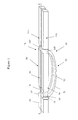
Figure 1 shows a perspective schematic view of a pair of articulated leg supports according to the invention mounted on an operating table; -
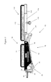
Figure 2 shows a side schematic view of a right hand side articulated leg support according to the invention in a lowered position; -
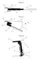
Figure 3 shows a side schematic view of the right hand side articulated leg support in a raised position; -
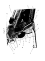
Figure 4 shows a schematic perspective view of part of the right hand side articulated leg support; -
Figure 5 shows a schematic side cross-sectional view of part of the right hand side articulated leg support; -
Figure 6 shows a schematic overhead perspective view of the right hand side articulated leg support in an initial position; -
Figure 7 shows a schematic overhead perspective view of the right hand side articulated leg support in a position abducted by an angle C from the initial position indicated by line B; -
Figure 8 shows a schematic end perspective view of the right hand side articulated leg support in a direction A shown onFigure 6 wherein the leg support is in a position laterally rotated from the initial position by an angle E; -
Figure 9 shows a schematic perspective view of a first embodiment of the upper leg cushion release mechanism; -
Figure 10 shows a schematic perspective view of a second embodiment of the upper leg cushion release mechanism in a first position; and -
Figure 11 shows a schematic perspective view of a second embodiment of the upper leg cushion release mechanism in a second position. -
Figure 1 shows a pair of articulatedleg sections 10,10' mounted on operating table 20. Right hand side articulatedleg section 10 corresponds to left hand side articulated leg section 10' in that eachleg section 10,10' has the same features but the former is arranged to support the right leg and the latter is arranged to support the left leg. - As shown in
Figures 1 ,2 and3 , right hand side articulatedleg section 10 has a connectingpiece 30, a hip joint 40, a hingedleg support 70 and alower leg section 110. - As shown in
Figures 2 and3 , hingedleg support 70 has alocking biasing mechanism 74 and a fourbar linkage 71 which is formed by hip joint 40,upper leg section 90, knee joint 100 andlower bar 72. - Connecting
piece 30,30' for mounting the articulatedleg section 10,10' on an operating table (not shown) is connected to thehip joint 40,40' which is for controlling the raising and rotating of the upper leg support. Hip joint 40,40' is connected to hingedleg support 70,70' for raising theupper leg section 90,90' whilst the lower leg section 110,110' remains parallel to the ground. Hingedleg support 70,70' is connected to the lower leg section 110,110'. - Right hand side articulated
leg support 10 is shown in more detail inFigures 2 ,3 ,4 and5 . Left hand side articulated leg support 10' corresponds. Connectingpiece 30 has aguide pin 32 and ananti-rotation pin 34 for engaging with corresponding apertures (not shown) on the operating table 20. Theguide pin 32 is for securing the articulatedleg support 10 to the operating table 20. Theanti-rotation pin 34 is for preventing the articulatedleg support 10 from rotating on theguide pin 32. - As shown in
Figure 5 , thelocking biasing mechanism 74 has alock release pin 75 which is resiliently biased to a closed position. Thelocking biasing mechanism 74 is pivotally mounted on the hip joint 40 by means ofpivot 76. Movement of the hingedleg support 70 is controlled by thelocking biasing mechanism 74. In one embodiment, thelocking biasing mechanism 74 is in the form of a locking compressible fluid strut, for example a locking gas spring. In an alternative embodiment, hingedleg support 70 is controlled by a biasing mechanism such as a spring and a separate cam operated spring-biased lock (not shown). - As shown in
Figures 4 and5 , hip joint 40 has aclamp 41 and aclamp release mechanism 60.Clamp 41 has an innerjoint arm 42, a outerjoint arm 44, afoam seal 53, anelement 46 and a key 48. - Inner
joint arm 42 has an upperleg section pivot 92, a concave, curved, element-facinginner surface 43, aslot 54 and anactuation dowel 47 which has adjustment screws 51. - Outer
joint arm 44 has alower arm pivot 73, a lockingbiasing mechanism pivot 76, a concave, curved, element-facinginner surface 45, aslot 49 and aprotrusion 50 which has a T-shapedtip 52. - Inner and outer
joint arms bolts 78. Inner and outerjoint arms joint arms joint arms -
Foam seal 53 is arranged between the innerjoint arm 42 and the outerjoint arm 44 to sealclamp 41 and to cushion and/or soften the relative movement of the innerjoint arm 42 and the outerjoint arm 44. -
Element 46 has asupport 31 which is mounted on connectingpiece 30.Element 46 has a curved surface and is provided in the form of a ball. It is located between inner and outerjoint arms surfaces joint arms element 46,element 46 has a flat surface (not shown) formed on its surface and key 48 is provided between inner and outerjoint arms joint arms Figure 8 . The inner facing surfaces of the inner and outerjoint arms joint arms joint arms joint arms element 46 and a key 48 provide a rotating joint. - The
surfaces joint arms joint arms Figure 7 bysurfaces support 31. - Abduction as used herein refers to anatomical movement of a patient's leg (not shown) about a vertical axis through the hip joint such that the leg moves horizontally in a direction away from the other leg. Abduction of the right hand side articulated
leg support 10 is illustrated inFigure 7. Figure 7 shows an articulatedleg support 10 which has been abducted by an angle C relative to the initial position of the articulatedleg support 10 which is shown inFigure 6 and by line B inFigure 7 . Angle C may be up to 25°. - Lateral rotation as used herein refers to anatomical movement of a patient's leg (not shown) when resting on articulated
leg section 10,10' such that the left leg, for example, is rotated anti-clockwise (from the viewpoint of the patient) at the hip about an axis parallel to the left leg in the anatomical position (i.e. away from the other leg). Lateral rotation of right hand side articulatedleg support 10 is illustrated inFigure 8. Figure 8 shows a view of an articulatedleg support 10 from direction A shown inFigure 7 . InFigure 8 , articulatedleg support 10 has been laterally rotated by an angle D relative to the vertical which is shown by line D inFigure 7 . Angle D may be up to 9°. - To limit the movement of the outer
joint arm 44 relative to the innerjoint arm 42 and to bias the outerjoint arm 44 towards the innerjoint arm 42, the T-shapedtip 52 of theprotrusion 50 of the outerjoint arm 44 is constrained to move in theslot 54 of the innerjoint arm 42 wherein theslot 54 contains a plurality ofBelleville washers 56 between the T-shapedtip 52 and the outer joint arm end of theslot 54. This is such that when pressure is applied to theclamp release mechanism 60 to move outerjoint arm 44 away from innerjoint arm 42, T-shapedtip 52 is moved throughslot 54 such that it abuts and compressesBelleville washers 56. When pressure is released from the joint release mechanism, the outerjoint arm 44 is returned to its normal position by the action of theBelleville washers 56 on the T-shapedtip 52. In an alternative embodiment, the plurality ofBelleville washers 56 may be replaced by a functionally equivalent resilient device such as a spring. Theprotrusion 50 of the outerjoint arm 44 and theslot 54 of the innerjoint arm 42 are provided below where surfaces 43,45surround element 46. The combination ofBelleville washers 56,slot 52 andprotrusion 50 provides a clamp bias mechanism for biasing theclamp 41 into a locked position. - The
actuation dowel 47 of the innerjoint arm 42, when acted upon by means of theclamp release mechanism 60, can be used to push apart inner and outerjoint arms element 46. When inner and outerjoint arms element 46. Theactuation dowel 47 extends throughslot 49 in the outerjoint arm 44. The length ofactuation dowel 47 may be adjusted by means of adjustment screws 51.Actuation dowel 47 of the innerjoint arm 42 andslot 49 of the outerjoint arm 44 are provided at a lower end of inner and outerjoint arms Actuation dowel 47 provides a formation to be acted upon by a first cam of theclamp release mechanism 60. - Inner and outer
joint arms joint arms element 46 and a second unlocked position. In the locked position of the inner and outerjoint arms joint arms joint arms joint arms element 46. -
Clamp release mechanism 60 is mounted on the innerjoint arm 44 and has ahandle 61 and acam arm 68.Cam arm 68 has anactuation lever 62 and areciprocating linkage 64.Actuation lever 62 has acylindrical formation 63 at its proximal end.Cylindrical formation 63 abutsactuation dowel 47 and has a needle roller bearing mounted on its external surface.Handle 61 is mounted off centre oncylindrical formation 63 at a point above the centre ofcylindrical formation 63 which is indicated onFigure 5 by cross-hairs 61. Thuscylindrical formation 63 providescam arm 68 with a first cam. A proximal end of reciprocatinglinkage 64 is rotatably mounted on a distal end ofactuation lever 62 such that there is an initial angle of about 90° between theactuation lever 62 and thereciprocating linkage 64. Reciprocatinglinkage 64 forms aslot 65 which is mounted onpivot 76. A distal end of reciprocatinglinkage 64 forms acurved cam surface 66.Curved cam surface 66 locates ontolock release pin 75 of thelocking biasing mechanism 74.Curved cam surface 66 providescam arm 68 with a second cam.Slot 65 has a lock release pin end and an actuation lever end. In a first position, reciprocatinglinkage 64 is mounted onpivot 76 such thatpivot 76 is at the lock release pin end ofslot 65. When acted upon byactuation lever 62, reciprocatinglinkage 64 is movable to a second position wherepivot 76 is at the actuation lever end ofslot 65. Thus clamprelease mechanism 60 is arranged so that both theclamp 41 and thelocking biasing mechanism 74 are released at the same time by the movement ofhandle 61. - As shown in
Figure 2 , theupper leg section 90 comprises anupper leg cushion 92 and anupper leg support 94. Thelower leg section 110 comprises alower leg cushion 112 and alower leg support 114.Lower leg support 114 is in the form of a tubular member on which thelower leg cushion 112 is slidably mounted.Lower leg cushion 112 has a tubular mounting 116 for receiving thelower leg support 114 so that thelower leg cushion 112 may be mounted on thelower leg support 114. Tubular mounting 116 has an adjustable screw fitting 118 so that the position oflower leg cushion 112 may be adjusted onlower leg support 114 and then fixed. - When the articulated
leg section 10 is in use, it may be desirable to remove the upper and lower leg cushions 92,112. Accordingly, theupper leg cushion 92 may be removable, for example by means of a leg cushion release mechanism 300,500 as illustrated inFigures 9-11 .Figure 3 shows the articulatedleg section 10 in a raised position where the upper and lower leg cushions 92,112 have been removed and where afoot receptacle 113 has been slidably mounted onlower leg support 114.Foot receptacle 113 has a tubular mounting 116 for receiving thelower leg support 114 so that thefoot receptacle 113 may be mounted on thelower leg support 114. Tubular mounting 116 has an adjustable screw fitting 118 so that the position offoot receptacle 113 may be adjusted onlower leg support 114 and then fixed. - The inner and outer
joint arms Figures 4 and5 and a second unlocked position. To move the inner and outerjoint arms handle 61 is lifted to cause theactuation lever 62 to rotate clockwise such that thecylindrical formation 63 acts as a cam surface by engagingactuation dowel 47 such that outerjoint arm 44 moves away from innerjoint arm 42, forcing inner and outerjoint arms cylindrical formation 63 onactuation dowel 47 is eased and effectively lubricated by the needle roller bearing which ensures that thehandle 61 can be easily moved and prevents there being two hard, inflexible metal surfaces grinding against each other. At the same time,actuation lever 62 acts upon reciprocatinglinkage 64 to move it from its first position to its second position. When reciprocatinglinkage 64 is in its second position, itscurved cam surface 66 engages and releases lockrelease pin 75 of thelocking biasing mechanism 74. - When the
handle 61 is released, the inner and outerjoint arms Belleville washers 56 on T-shapedtip 52 and by the resilience of the inner and outerjoint arms actuation dowel 47 acts oncylindrical formation 63 to returncam arm 68 and handle 61 to its original position. In an alternate embodiment,lock release pin 75 may be resiliently biased to return to a closed position to lock lockingbiasing mechanism 74, thereby acting on reciprocatinglinkage 64 to move it to its first position and to thereby assist in the movement ofcam arm 68 and handle 61 to their original positions. - When the inner and outer
joint arms joint arms joint arms leg support 70 up and down. When hingedleg support 70 is moved up, any weight, such as the weight of a patient's leg, is supported by the resilience and the biasing of thelocking biasing mechanism 74. This is because thelocking biasing mechanism 74 biases the hingedleg support 70 to be in a raised position. Where thelocking biasing mechanism 74 is a locking gas strut, thelocking biasing mechanism 74 is compressed when the hingedleg support 70 is the initial lowered position and extended when it is in a raised position. - When the hinged
leg support 70 is moved up, thelower leg section 110 remains parallel to the ground because thelower bar 72 is of fixed length. In some circumstances, hinged movement of thelower leg section 110 may be desired. Accordingly, in an alternate embodiment,lower bar 72 is replaced by a member having a variable length (not shown) such that the orientation of thelower leg section 110 may be independently manipulated to allow fine tuning of the position of thelower leg section 110. A member having a variable length may be a locking biasing mechanism as defined herein. -
Figure 9 shows a first embodiment of the legcushion release mechanism 300. Therelease mechanism 300 is for releasably attaching aleg cushion 400 to aupper leg support 94. - The
leg cushion 400 has a length and a width. Theleg cushion 400 also has aproximal end 404 and adistal end 408. The leg cushion has aleg facing surface 430 and an opposing legsupport facing surface 440. On the opposingsurface 440, a pair of catch pins 420 and a pair offemale hinge elements 410 are mounted. - The
upper leg support 94 has a length, aproximal end 304 which may be connected to innerjoint arm 42 of theclamp 60 and adistal end 308 which may be connected to a knee joint (not shown). - The
upper leg support 94 has anupper surface 310 on which theleg cushion 400 may be mounted, aninner surface 330 which faces the other leg support (not shown) in use and anouter surface 320. Spaced apart on theinner surface 330 and coaxially mounted are provided a pair ofmale hinge elements 360 having axes arranged parallel to the length of theupper leg support 94. Each of themale hinge elements 360 has a protrusion. Each of the pair offemale hinge elements 410 on theleg cushion 400 forms a receptacle which is arranged to engage the protrusion of one of the pair ofmale hinge elements 360. - In an alternate embodiment, one or both of the pair of male and female hinge elements 360,410 may be switched such that one or both of the
male hinge elements 360 is located on theleg cushion 400 and one or both of thefemale hinge elements 410 is located on theupper leg support 94. - Spaced apart on the
upper surface 310 are formed a pair ofapertures 340. Each of the pair of catch pins 420 on theleg cushion 400 is arranged to engage each of the pair ofapertures 340. On theouter surface 320, acatch release button 350 is provided. - Inside the
upper leg support 94, a catch mechanism (not shown) is provided. The catch mechanism (not shown) is arranged to engage the pair of catch pins 420 when they are inserted into the pair ofapertures 340. The catch mechanism (not shown) is arranged to release the catch pins 420 so that they can be removed from the pair ofapertures 340 when thecatch release button 350 is operated. - In operation, to mount the
leg cushion 400 on theupper leg support 94, theleg cushion 400 is placed against the distal end of theupper leg support 94 such that its opposingsurface 440 is againstinner surface 330 and such that each of the pair offemale hinge elements 410 on theleg cushion 400 is distal to its corresponding one of the pair ofmale hinge elements 360. Theleg cushion 400 is then slid longitudinally along upperupper leg support 94 in a proximal direction so that each of the pair offemale hinge elements 410 on theleg cushion 400 engages its corresponding one of the pair ofmale hinge elements 360. Theleg cushion 400 is then rotated about the axis of theupper leg support 94 such that the opposingsurface 440 is against theupper surface 310 of theupper support 300 and such that the pair of catch pins 420 are inserted into the pair ofapertures 340 and engage the catch mechanism (not shown). - Conversely, to remove the
leg cushion 400 from theupper leg support 94, thecatch release button 350 is operated and then the steps set out in the preceding paragraph are performed in reverse order. Thus theleg cushion 400 may be removed from theupper leg support 94 whilst in use without a patient having to move their legs. This is because the leg cushion is swung below the patient's leg to remove it. Thus, it does not have to be lifted off theupper leg support 94. - A second embodiment of the leg
cushion release mechanism 500 is shown inFigures 10 and11 . Therelease mechanism 500 is for releasably attaching aleg cushion 600 to aleg support 94. Like features of legcushion release mechanism 500 andleg cushion 600 to legcushion release mechanism 300 andleg cushion 400 are indicated by like reference numbers. - The
leg cushion 400 has a length and a width. Theleg cushion 400 also has a proximal end (not shown) and a distal end (not shown). The leg cushion has aleg facing surface 430 and an opposing legsupport facing surface 440. On the opposingsurface 440, a pair of catch pins 420 and a pair ofhooks 610 are mounted. - The
upper leg support 94 has a length, aproximal end 304 which may be connected to innerjoint arm 42 of theclamp 60 and a distal end (not shown) which may be connected to a knee joint (not shown). - The
upper leg support 94 has anupper surface 310 on which theleg cushion 400 may be mounted, aninner surface 330 which faces the other leg support (not shown) in use and anouter surface 320. Arail 560 is provided on theinner surface 330 having an axis arranged parallel to the length of theupper leg support 94. The pair ofhooks 610 on theleg cushion 400 are shaped to engagerail 560. - Spaced apart on the
upper surface 310 are formed a pair ofapertures 340. Each of the pair of catch pins 420 on theleg cushion 400 is arranged to engage each of the pair ofapertures 340. On theouter surface 320, acatch release button 350 is provided. - Inside the
upper leg support 94, a catch mechanism (not shown) is provided. The catch mechanism (not shown) is arranged to engage the pair of catch pins 420 when they are inserted into the pair ofapertures 340. The catch mechanism (not shown) is arranged to release the catch pins 420 so that they can be removed from the pair ofapertures 340 when thecatch release button 350 is operated. - In operation, to mount the
leg cushion 600 on theupper leg support 94, theleg cushion 600 is placed against theupper leg support 94 such that hooks 610 on theleg cushion 400 engagerail 560 as shown inFigure 11 . Theleg cushion 400 is then rotated aboutrail 560 such that the opposingsurface 440 is against theupper surface 310 of theupper support 300 and such that the pair of catch pins 420 are inserted into the pair ofapertures 340 and engage the catch mechanism (not shown). - Conversely, to remove the
leg cushion 400 from theupper leg support 94, thecatch release button 350 is operated and then the steps set out in the preceding paragraph are performed in reverse order. Thus theleg cushion 400 may be removed from theupper leg support 94 whilst in use without a patient having to move their legs. This is because the leg cushion is swung below the patient's leg to remove it. Thus, it does not have to be lifted off theupper leg support 94.
wherein the catch mechanism has a release button provided on a surface of the leg support which release button is for releasing the catch mechanism such that the leg cushion may be removed from the leg support.
Claims (15)
- An articulated leg section for supporting a leg of a patient wherein the leg section comprises a hinged leg support, a rotating joint for rotation of the leg support and a clamp for controlling movement of the hinged leg support and the rotating joint wherein:the rotating joint has a locked position and an unlocked position;the hinged leg support may be locked; andthe clamp is actuable to unlock the rotating joint and the hinged leg support.
- A leg section according to Claim 1 wherein the rotating joint and/or the hinged leg support are adapted to only allow an anatomically acceptable movement of a patient's leg.
- A leg section according to Claim 2 wherein the rotating joint is a laterally rotating joint for rotating an upper part of a patient's leg laterally by an angle of up to about 30°, preferably up to about 20°, more preferably up to about 10°.
- A leg section according to Claim 2 or Claim 3 wherein the rotating joint is an abducting joint for abducting a patient's leg by an angle of up to about 45°, preferably up to about 35°, more preferably up to about 25°.
- A leg section according to any one of the preceding claims wherein the hinged leg support is a four bar linkage.
- A leg section according to any one of the preceding claims wherein the hinged leg support includes a biasing mechanism for biasing the hinged leg support into a raised position, preferably the biasing mechanism is a resilient member.
- A leg section according to Claim 6 wherein the biasing mechanism may be a damped biasing mechanism, preferably the biasing mechanism is a locking biasing mechanism.
- A leg section according to any one of the preceding claims wherein the clamp has a cam arm having a first and a second cam wherein the cam arm is rotatable from a first rest position where the rotating joint and hinged leg support are locked to a second position where the first cam engages the rotating joint to unlock it and the second cam engages the hinged leg support to unlock it.
- A leg section according to claim 8 wherein the joint arm has a formation for engaging the first cam.
- A leg section according to claim 8 or claim 9 wherein the second cam is provided by a reciprocating linkage having a cam surface.
- A leg section according to any one of the preceding claims wherein the clamp has a clamp bias mechanism for biasing it into a locked position.
- A leg section according to any one of the preceding claims which has a connecting piece to enable it to be removably mounted on a patient support device.
- A patient support device comprising an articulated leg section as defined in any one of the preceding claims.
- A cushion release mechanism comprising:a leg support having a cushion facing upper surface on which is formed one or more apertures and a side surface on which one or more co-axial first hinge elements are provided; anda leg cushion having a leg facing surface and an opposing surface on which one or more catch pins and one or more co-axial second hinge elements are provided;wherein the one or more catch pins are positioned so that in use the one or more catch pins engage the one or more apertures; wherein the one or more first hinge elements are positioned so that in use the one or more first hinge elements removably engage the one or more second hinge elements; wherein the leg support has a catch mechanism for engaging the one or more catch pins when inserted in the one or more apertures; and wherein the catch mechanism has a release button provided on a surface of the leg support which release button is for releasing the catch mechanism such that the leg cushion may be removed from the leg support.
- A cushion release mechanism as defined in Claim 14 wherein the first hinge elements are male or female hinge elements and wherein the second hinge elements are corresponding female or male hinge elements.
Applications Claiming Priority (1)
| Application Number | Priority Date | Filing Date | Title |
|---|---|---|---|
| GB0810814A GB2460863B (en) | 2008-06-12 | 2008-06-12 | Articulated leg section |
Publications (2)
| Publication Number | Publication Date |
|---|---|
| EP2133057A2 true EP2133057A2 (en) | 2009-12-16 |
| EP2133057A3 EP2133057A3 (en) | 2010-01-27 |
Family
ID=39672209
Family Applications (1)
| Application Number | Title | Priority Date | Filing Date |
|---|---|---|---|
| EP09251519A Withdrawn EP2133057A3 (en) | 2008-06-12 | 2009-06-09 | Articulated leg section |
Country Status (2)
| Country | Link |
|---|---|
| EP (1) | EP2133057A3 (en) |
| GB (1) | GB2460863B (en) |
Citations (5)
| Publication number | Priority date | Publication date | Assignee | Title |
|---|---|---|---|---|
| US5209509A (en) * | 1990-05-26 | 1993-05-11 | Gunnell, Inc. | Wheelchair footrest assembly |
| DE4406553C1 (en) * | 1994-03-01 | 1995-07-20 | Stierlen Maquet Ag | Leg-plate attachment to operating table |
| US5802641A (en) * | 1997-03-07 | 1998-09-08 | Amatech Corporation | Leg holder system for simultaneous positioning in the abduction and lithotomy dimensions |
| US6289537B1 (en) * | 2000-02-09 | 2001-09-18 | Stryker Corporation | Patient support |
| US20060117485A1 (en) * | 2004-12-03 | 2006-06-08 | Brophy Joseph T | Maternity bed foot support and abduction assembly |
Family Cites Families (3)
| Publication number | Priority date | Publication date | Assignee | Title |
|---|---|---|---|---|
| US5645079A (en) * | 1994-12-02 | 1997-07-08 | Zahiri; Hormoz | Apparatus for mechanically holding, maneuvering and maintaining a body part of a patient during orthopedic surgery |
| DE10253906A1 (en) * | 2002-11-19 | 2004-06-03 | Maquet Gmbh & Co. Kg | Leg plate arrangement for operating tables |
| US7243654B2 (en) * | 2005-04-08 | 2007-07-17 | Peter Schuerch | Adjustable position limb support for surgical tables |
-
2008
- 2008-06-12 GB GB0810814A patent/GB2460863B/en not_active Expired - Fee Related
-
2009
- 2009-06-09 EP EP09251519A patent/EP2133057A3/en not_active Withdrawn
Patent Citations (5)
| Publication number | Priority date | Publication date | Assignee | Title |
|---|---|---|---|---|
| US5209509A (en) * | 1990-05-26 | 1993-05-11 | Gunnell, Inc. | Wheelchair footrest assembly |
| DE4406553C1 (en) * | 1994-03-01 | 1995-07-20 | Stierlen Maquet Ag | Leg-plate attachment to operating table |
| US5802641A (en) * | 1997-03-07 | 1998-09-08 | Amatech Corporation | Leg holder system for simultaneous positioning in the abduction and lithotomy dimensions |
| US6289537B1 (en) * | 2000-02-09 | 2001-09-18 | Stryker Corporation | Patient support |
| US20060117485A1 (en) * | 2004-12-03 | 2006-06-08 | Brophy Joseph T | Maternity bed foot support and abduction assembly |
Also Published As
| Publication number | Publication date |
|---|---|
| EP2133057A3 (en) | 2010-01-27 |
| GB0810814D0 (en) | 2008-07-23 |
| GB2460863A (en) | 2009-12-16 |
| GB2460863B (en) | 2012-10-03 |
Similar Documents
| Publication | Publication Date | Title |
|---|---|---|
| EP1685818B1 (en) | Birthing support apparatus | |
| US20200315892A1 (en) | Modular multi-articulated pateint support system | |
| US9480616B2 (en) | Surgical table with pivotable femoral support | |
| EP2753286B1 (en) | Operating tables and accessories | |
| JP5893819B2 (en) | Waist distraction device and method | |
| US20180200131A1 (en) | Extremity Surgical Positioning Device | |
| US8322342B2 (en) | Operative arm support | |
| US10045901B2 (en) | Carriage for a surgical boot of a hip distractor | |
| TW570766B (en) | Patient support apparatus | |
| US20220387238A1 (en) | Patient positioning support apparatus with fail-safe connector attachment mechanism | |
| US20110023893A1 (en) | Modular device for positioning and immobilisation of a patient's body for surgical operations and corresponding operating table | |
| US5369825A (en) | All purpose surgery table | |
| US20100295357A1 (en) | Chest support | |
| US10893995B2 (en) | Lift for extremity surgical positioning device | |
| EP2895132B1 (en) | Telescoping and elevating femoral support | |
| JP2018057904A (en) | Boot stirrup | |
| EP2617405B1 (en) | Leg support for a surgical table | |
| WO2009105293A1 (en) | Ambulatory surgical gurney | |
| US20100192302A1 (en) | Extremity support apparatus | |
| EP2133057A2 (en) | Articulated leg section | |
| WO2013181277A1 (en) | Wound care apparatus and methods for using the same | |
| EP1148859B1 (en) | Support apparatus for seated patient | |
| US20100192301A1 (en) | Extremity support apparatus for an emergency cot | |
| US20220233383A1 (en) | Medical procedure facilitation system |
Legal Events
| Date | Code | Title | Description |
|---|---|---|---|
| PUAI | Public reference made under article 153(3) epc to a published international application that has entered the european phase |
Free format text: ORIGINAL CODE: 0009012 |
|
| AK | Designated contracting states |
Kind code of ref document: A2 Designated state(s): AT BE BG CH CY CZ DE DK EE ES FI FR GB GR HR HU IE IS IT LI LT LU LV MC MK MT NL NO PL PT RO SE SI SK TR |
|
| PUAL | Search report despatched |
Free format text: ORIGINAL CODE: 0009013 |
|
| AK | Designated contracting states |
Kind code of ref document: A3 Designated state(s): AT BE BG CH CY CZ DE DK EE ES FI FR GB GR HR HU IE IS IT LI LT LU LV MC MK MT NL NO PL PT RO SE SI SK TR |
|
| AX | Request for extension of the european patent |
Extension state: AL BA RS |
|
| STAA | Information on the status of an ep patent application or granted ep patent |
Free format text: STATUS: THE APPLICATION IS DEEMED TO BE WITHDRAWN |
|
| 18D | Application deemed to be withdrawn |
Effective date: 20100728 |