EP2124709B1 - Flexible endoscope device with visual control - Google Patents
Flexible endoscope device with visual control Download PDFInfo
- Publication number
- EP2124709B1 EP2124709B1 EP08762153.8A EP08762153A EP2124709B1 EP 2124709 B1 EP2124709 B1 EP 2124709B1 EP 08762153 A EP08762153 A EP 08762153A EP 2124709 B1 EP2124709 B1 EP 2124709B1
- Authority
- EP
- European Patent Office
- Prior art keywords
- image
- visual
- endoscope
- control
- end segment
- Prior art date
- Legal status (The legal status is an assumption and is not a legal conclusion. Google has not performed a legal analysis and makes no representation as to the accuracy of the status listed.)
- Not-in-force
Links
Images


Classifications
-
- A—HUMAN NECESSITIES
- A61—MEDICAL OR VETERINARY SCIENCE; HYGIENE
- A61B—DIAGNOSIS; SURGERY; IDENTIFICATION
- A61B1/00—Instruments for performing medical examinations of the interior of cavities or tubes of the body by visual or photographical inspection, e.g. endoscopes; Illuminating arrangements therefor
- A61B1/04—Instruments for performing medical examinations of the interior of cavities or tubes of the body by visual or photographical inspection, e.g. endoscopes; Illuminating arrangements therefor combined with photographic or television appliances
- A61B1/05—Instruments for performing medical examinations of the interior of cavities or tubes of the body by visual or photographical inspection, e.g. endoscopes; Illuminating arrangements therefor combined with photographic or television appliances characterised by the image sensor, e.g. camera, being in the distal end portion
-
- A—HUMAN NECESSITIES
- A61—MEDICAL OR VETERINARY SCIENCE; HYGIENE
- A61B—DIAGNOSIS; SURGERY; IDENTIFICATION
- A61B1/00—Instruments for performing medical examinations of the interior of cavities or tubes of the body by visual or photographical inspection, e.g. endoscopes; Illuminating arrangements therefor
- A61B1/00147—Holding or positioning arrangements
-
- A—HUMAN NECESSITIES
- A61—MEDICAL OR VETERINARY SCIENCE; HYGIENE
- A61B—DIAGNOSIS; SURGERY; IDENTIFICATION
- A61B1/00—Instruments for performing medical examinations of the interior of cavities or tubes of the body by visual or photographical inspection, e.g. endoscopes; Illuminating arrangements therefor
- A61B1/005—Flexible endoscopes
- A61B1/0051—Flexible endoscopes with controlled bending of insertion part
Definitions
- the present invention relates to the field of equipment and instruments for medical use, particularly the equipment of operating rooms, medical investigation rooms and medical practices, and relates to a flexible endoscope device with visual servoing and a method of actively stabilizing such an endoscope.
- the object of the present invention is to propose a solution that makes it possible to overcome the physiological movements, and more generally, the disturbances generated by the environment of the endoscope, and to facilitate precise control of the latter by the practitioner, in particular relieving him of certain control and control tasks, without modifying the internal constitution of the endoscope or its mode of operation.
- the basic principle implemented by the invention consists, preferentially iteratively, to estimate the pointing error of the endoscope with respect to a target and to develop a command, in real time, to lower or cancel this pointing error.
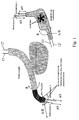
- FIG. 2 of the accompanying drawings shows a flexible endoscope device 1 comprising an elongate flexible body 2 having a flexible end segment 3 carrying or shaping the head 3 'of the endoscope, provided with an optical system 4 and being curvable or flexed in at least two mutually perpendicular directions.
- the elongated body 2 being functionally connected, at its other end, to a control means 5 able to control at least the movements and / or the disposition of said end segment 3.
- part of the video processing means 6, or that certain functions performed by the latter, are located in the optical system 4.
- the latter can also be in different embodiments, namely: a video camera embedded in the endoscope at the end segment 3 of the flexible elongate body 2; a bundle of optical fibers opening at the end segment 3 and connected to a video camera or similar external device (fiberscope); a bundle of optical microfibers mounted in the body 2 and connected to an external operating device (cellular fibroscopy device) or the like.
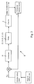
- the computer means 7 therefore produces a digital control by visual servoing and contains a software model of the complex physical system formed by the endoscope, these mechanical control means and its motorization, said modeling processing the input signals formed by the image reference 10 and the current image 10 'and outputting control signals for the means (s) actuator (s) 8, 8'.
- the images provided by the optical system 4 and used in the form of video images are used to control the movements of the flexible endoscope, more particularly of its head 3 '(see in this connection in particular: " A tutorial on visual servo control ", S. Hutchinson, GD Hager and PI Corke, IEEE Transactions on Robotics and Automation, Vol 12, 5, pp. 651-670, 1996 ).
- the working environment in which the head 3 'of the endoscope is located usually does not present particular visual cues such as points of interest, corners, contours of particular rigid shapes, straight lines or analogous, and therefore does not directly allow the application of known methods of extraction, coincidence, tracking and servocontrol, without setting up additional markers in the work environment.
- the computer means 7 is capable, by execution of a suitable program, of determining, in real time, that is to say at least at the speed of delivery of the video images, an approximation, preferentially by iterative processing, the transformation to be applied to the current image 10 'resulting in a minimization of a cost function between a reduced or imagined image T * obtained from the reference image 10 and a reduced image or image T obtained from the current image 10 'provided by the head 3' of the endoscope and processed by the current approximated transformation.
- the information useful for visual servoing relies on an algorithm of the type "visual reference thumbnail tracking".
- the reference zone is learned during the manual selection, by the practitioner, of the target zone to be stabilized.
- the monitoring of this zone is then ensured by minimizing a measure of dissimilarity between the reference thumbnail T * and the current thumbnail T.
- reference image is meant herein the image in which the practitioner has identified the anatomical target. It is normally constituted by an initial image or base provided by the video means connected to the endoscope 2 or possibly a stored image, for example a real image of the anatomical environment of the target acquired by selection.
- the minimization algorithm implemented by the computer means 7 performs a parametric minimization of the quadratic error between the visual or visual information elements T * and T respectively obtained from the image. reference 10 and from the current image 10 ', the approximated transformation being a plane transformation, for example, homographic type.
- the minimization algorithm may, for example, be derived from an ESM type algorithm, as described in particular in the publication " Improving vision-based control using efficient second-order minimization techniques ", MALIS E., IEEE Int.Conf.on Rob.Aut.A., Pages 1843-1848, 2004 .
- the minimization algorithm implemented by the computer means 7 performs a statistical minimization of a measurement of dissimilarity between histograms obtained from the visual elements or visual information T * and T respectively obtained from the reference image 10 and from the current image 10 ', the approximated transformation being composed of a translation in the image plane and a zoom (reduction or enlargement).
- the minimization algorithm can be derived from that known under the designation "mean-shift” algorithm, as described for example in: " Kermel-based object tracking ", D. Comanicin et al., Patterne Analysis and Machine Intelligence, IEEE Transactions on, Volume 25, May 5, 2003, pages: 564-577 .
- the vector of the variable S ref preparamétrée contains the image data to which the anatomical target must be stabilized. This point is initially selected by the practitioner on the reference image 10 and can be modified in the current image 10 '. The practitioner also specifies the point of interest of the anatomical target to stabilize s * in the reference image T *.
- One of the above-mentioned tracking algorithms is then used to reconstruct the transformation between the current image T and the reference image T *, this transformation being then used to determine the vectors containing the coordinates of the point to be stabilized in the current image. .
- the automatic positioning means 6, 7, 8, 8 ' are organized in a two-dimensional visual servocontrol loop and comprise two independent actuators 8 and 8' each controlling the movements and the positioning of the segment end 3 in one of the two mutually perpendicular directions corresponding to the two directions of the current planar image provided by the endoscope head 3 '.
- an independent control loop 9 is provided for each actuator means 8, 8 ', depending on the nature of the system.
- the controller or corrector 11 forming part of the control loop 9 can be chosen from the group formed by the controllers of the proportional type, of the proportional / integral / derivative type and of the predictive or repetitive type.
- controller 11 of the repetitive type as described for example in: " Analysis and Synthesis of Discrete-Time Repetitive Controllers ", M. Tomizuka et al., American Society of Mechanical Engineers Journal of Dynamic Systems, Measurement and Control, 111, 353-358, 1989 ; a controller of the R-GPC type as described for example in: Model Predictive Control for Panning of Cyclic Organ Motions in Teleoperated Laparoscopic Surgery, J. Gangloff et al., Control Systems Technology, IEEE Transactions on, Volume 14, Issue 2, March 2006, pages 235-246. .
- the controller 11 can also integrate a model of the perturbation, as for example in the predictive controller described in the publication of EF Camacho, Bordons C, Model Predictive Control, ISBN 3-540-76241-8 .
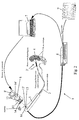
- the control means 5 comprises two concentric control axes 13 and 13 'each associated with a control cable 12, 12' flowing along the elongate body 2 and connected to the end segment 3 to control the bending or bending of said segment 3 in one of two mutually perpendicular bending directions, the outer axis 13 being in drive relation with a first actuator means 8 in the form of a hollow shaft motor 8 "via a transmission part 14 disengaged in a central region extending in the continuity of the hollow axis 8 "of said motor 8, and the inner axis 13 'being in driving relation, via a piece of elongate drive 14 ', with a second actuator means 8' in the form of a motor aligned with the first motor 8 along their axes of rotation, said elongate drive member 14 'passing through the first motor 8 at its hollow axis 8 ".
- the two motors 8 and 8 ' are mechanically assembled together to form a drive unit mounted on the handle 5 forming the control means, through a support part 15 and fastening, where appropriate in form unit with removable mechanical connection, thus allowing interchangeability with the manual control elements ( figure 2 ).
- the non-limiting embodiment of motorization of the control of a flexible endoscope illustrated on the figures 2 and 6 to 8 , more particularly relates to an endoscope type 13801 PKS KARL STORZ company.
- the motorization solution proposed by the invention makes it possible to preserve the existing internal structure of the endoscope, by recommending the replacement of the manual control wheels by the actuators 8 and 8 '.
- the latter are for example in the form of harmonic control motors (for example of the FHA-8C type) controlled by servocontrollers with a speed loop (for example of the Harmonic Drive SC-610 type). Said motors are connected directly to the control pins 13 and 13 ', by rigid mechanical connection and without clutch or articulation, in order to avoid as much play as possible.
- harmonic control motors for example of the FHA-8C type
- servocontrollers with a speed loop for example of the Harmonic Drive SC-610 type
- the endoscope device 1 being a mechanical system with 2 degrees of freedom
- the two x and y coordinates of a visual index of the point type in the image is a sufficient feedback variable. to control said system.
- the velocity of the visual index F (s) in the image is related to the velocity of the actuators Q by a 2x2 interaction matrix, which the inventors have chosen to estimate in a preliminary phase around the working configuration.
- the velocity vector of the actuators Q (s) * is sent as a reference to the speed loops of the power amplifiers controlling the motors of the actuators 8 and 8 '.
- the bandwidth of said speed loops being significantly greater than the sampling frequency of the visual servo loop 9, the dynamics of the actuators can be neglected and therefore Q (s) is approximately equal to Q (s) *.
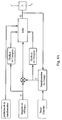
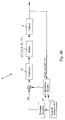
- the main branch of the loop successively comprises the following elements: zero order corrector / blocker BOZ / integrator 1 / s / hysteresis module (set of sets of device 1) / interaction matrix J (s) / integrator 1 / s and the feedback branch comprises a delay element Z -1 which corresponds to the acquisition times of the images.
- This part 15 is furthermore configured in such a way as to ensure axial alignment of the motors 8 and 8 'with the concentric control axes 13 and 13'.
- This part 15 directly supports the lower motor 8 and indirectly the upper motor 8 ', the latter by means of an additional support member 15', simultaneously secured to said part 15 and to said motor 8 '( figures 2 and 6 ).
- the part 14 for transmitting the movement between the lower motor 8 and the external control shaft 13 has an unobstructed central region (in the axial direction of the two motors in the assembled state), and is provided at its bottom. a square cut for an engagement adjusted on the outer axis 13 and at its upper part of sites engagement with the output flange of the lower motor 8 with hollow shaft (for example connection pins / orifices).
- the driving part 14 ' ensuring the transmission of the movement between the upper motor 8' and the inner axis 13 ', comprises a lower connection portion (with a square section opening) intended to engage on said axis 13 and an upper connection interface in engagement with the upper motor output flange 8 '(e.g. via a lug / port connection).
- the upper motor 8 ' is maintained in axial alignment with the lower motor 8 and the control pins 13 and 13' via the additional support piece 15 '.
- the actuator means 8, 8 ' can also be in the form of motors directly housed in the handle forming the control means 5 and in driving relation each with a cable for controlling the bending deformation of the end segment 3.
- control means 5 may also comprise at least one member that can be manipulated by the practitioner, such as a thumbwheel, a joystick or the like, able to control at least one actuator 8, 8 ', alternatively or superimposed manner with respect to the automatic control by visual servoing, said member (s) being (s) mounted (s) at the handle 5, or remote (s) relative thereto.
- This method implements a flexible endoscope device 1 essentially comprising an elongate flexible body 2 having a flexible end segment 3 carrying or forming the endoscope head 3 ', provided with an optical system 4 and being curved or flexed according to at least two mutually perpendicular directions, said elongated body 2 being functionally connected at its other end (opposite or segment 3) to a control means 5 adapted to control at least the movements and / or the disposition of said end segment, plus particularly a device as described above.
- This method consists in automatically performing, by means of means 6, 7, 8 and 8 'of automatic bending and positioning of the end segment 3 organized functionally in at least one servo loop 9, a processing of the images provided. by the optical system 4 of the head 3 'of the endoscope, visual servoing operations on the basis of the processed video signals and the development and supply of control signals to actuator means 8, 8' forming part or associated with the control means 5.
- the servo-control operations essentially consist in minimizing the error or a similar measure of dissimilarity between, on the one hand, a target visual or visual information element extracted from a reference image 10 and, on the other hand, a corresponding visual or visual information element extracted from the current image 10 'provided by the optical system 4 of the endoscope head 3', said error being used to deliver control signals to the medium (s) actuator (s) 8, 8 'controlling the movements and the positioning of said end segment 3 in at least one direction.
- the visual or visual information elements are chosen from the group formed by the visual patterns, the image reductions and the image portions or zones respectively obtained from the reference image 10 and from the image current 10 'provided by the optical system 4, if appropriate after suitable treatment thereof.
- the method consists, in the context of servocontrol operations carried out by the computer means 7, to determine in real time, that is to say at least at the speed of supply of the video images. , an approximation, preferably by iterative processing, of the transformation to be applied to the current image 10 'resulting in a minimization of a cost function between a reduced or an imaginary image T * obtained from the reference image 10 and a reduced or enlarged image obtained from the reference image 10 'provided by the endoscope head 3' and processed by the current approximated transformation.
- the latter can consist in implementing a minimization algorithm performing a parametric minimization of the quadratic error between the visual or visual information elements T * and T respectively obtained from the image of reference 10 and from the current image 10 ', the approximated transformation being a plane transformation, for example of a homographic type.
- the latter can consist in implementing a minimization algorithm achieving a statistical minimization of a measure of dissimilarity between histograms obtained from the visual elements or visual information T * and T respectively obtained at from the reference image 10 and from the current image 10 ', the approximated transformation being composed of a translation in the image plane and a zoom.
- the movements and positioning of the end segment 3 ' are controlled by two independent actuators 8 and 8' each associated with one of two perpendicular directions corresponding to two directions of the current plane image 10 ' repeatedly provided by the endoscope head 3 '.
- the parameterization phase may consist, for the practitioner, in determining the reference s ref of the servocontrol loop 9, in the form of appropriate visual cues (for example x, y coordinates of a point) selected in an image of 10, to control the various degrees of freedom of the flexible endoscope, in particular of its free end 3.
Description
La présente invention concerne le domaine des équipements et des instruments à usage médical, plus particulièrement les équipements de salles d'opérations, de salles d'investigation médicales et de cabinets médicaux, et a pour objet un dispositif d'endoscope flexible à asservissement visuel et un procédé de stabilisation active d'un tel endoscope.The present invention relates to the field of equipment and instruments for medical use, particularly the equipment of operating rooms, medical investigation rooms and medical practices, and relates to a flexible endoscope device with visual servoing and a method of actively stabilizing such an endoscope.
Les endoscopes flexibles sont bien connus et utilisés depuis de nombreuses années dans une pluralité d'applications médicales, aussi bien à des fins de diagnostics qu'à des fins opératoires ou d'assistance opératoire.Flexible endoscopes are well known and have been used for many years in a variety of medical applications, for diagnostic purposes as well as for operative purposes or operative assistance.
Chaque procédure nécessite généralement un endoscope flexible spécifique qui est adapté en conséquence et qui se distingue par sa longueur, son diamètre, la manoeuvrabilité de son extrémité invasive, ses accessoires, les outils ou instruments qu'il peut intégrer, ...Each procedure generally requires a specific flexible endoscope that is adapted accordingly and that is distinguished by its length, its diameter, the maneuverability of its invasive end, its accessories, the tools or instruments that it can integrate, ...
Toutefois, sur l'ensemble des endoscopes flexibles actuels, il est possible de mettre en évidence systématiquement au moins les trois parties constitutives suivantes :
- un moyen de commande manuel externe, généralement sous la forme d'une poignée de commande pourvue d'au moins un, préférentiellement deux, organes de commande sous forme de molettes ou analogues;
- un corps allongé souple et flexible, généralement à section circulaire et dans lequel sont ménagés plusieurs canaux longitudinaux pour le passage d'instruments ou de câbles de manoeuvre;
- une extrémité invasive fonctionnelle, notamment sous la forme d'un segment d'extrémité flexible du corps allongé (située à l'opposé de la poignée de commande), qui porte ou forme la tête de l'endoscope, est muni d'un système optique (par exemple du type caméra vidéo CCD ou faisceau de fibre optique) et qui peut être courbé ou fléchi selon au moins deux directions préférentiellement mutuellement perpendiculaires.
- external manual control means, generally in the form of a control handle provided with at least one, preferably two, control members in the form of wheels or the like;
- an elongated flexible and flexible body, generally of circular section and in which are formed several longitudinal channels for the passage of instruments or operating cables;
- a functional invasive end, in particular in the form of a flexible end segment of the elongate body (located opposite the control handle), which carries or forms the head of the endoscope, is provided with a system optical (eg CCD video camera type or optical fiber beam) and which can be bent or flexed in at least two directions preferably mutually perpendicular.
Les canaux du corps allongé s'étendent également à travers ce segment d'extrémité au niveau duquel ils débouchent.The channels of the elongate body also extend through this end segment at which they open.
L'actionnement de la tête de l'endoscope, c'est-à-dire l'angle de déflexion du segment d'extrémité, est contrôlé par des câbles de manoeuvre courant le long du corps allongé et reliés aux organes de commande.The actuation of the head of the endoscope, that is to say the deflection angle of the end segment, is controlled by operating cables running along the elongate body and connected to the control members.
Pour naviguer dans le corps du sujet, et ainsi contrôler la trajectoire de l'endoscope ou guider un ou plusieurs instruments vers une zone ou un organe cible, le praticien utilise les images fournies par le système optique, embarqué dans la partie active (caméra CCD, fibre optique). L'éclairage de la scène est également assuré par l'endoscope via des fibres optiques débouchant au niveau de l'extrémité fonnant tête. Le praticien agit activement sur l'endoscope en manipulant le corps allongé (translation et rotation) par él'intermédiaire de la poignée et contrôle positivement la flexion du segment d'extrémité dans au moins deux directions orthogonales.To navigate the body of the subject, and thus control the trajectory of the endoscope or guide one or more instruments to a target area or organ, the practitioner uses the images provided by the optical system, embedded in the active part (CCD camera , optical fiber). Stage lighting is also provided by the endoscope via optical fibers opening at the leading end. The practitioner actively acts on the endoscope by manipulating the elongated body (translation and rotation) through the handle and positively controls flexion of the end segment in at least two orthogonal directions.
Une fois sur le site opératoire, le praticien peut passer des instruments comme, par exemple, des pinces, des ciseaux, un crochet, un bistouri, une fibre laser ou encore une aiguille, selon le type d'intervention à réaliser, et les interchanger par la suite sans modifier la position de l'endoscope.Once on the operating site, the practitioner can pass instruments such as, for example, pliers, scissors, a hook, a scalpel, a laser fiber or a needle, depending on the type of intervention to be performed, and interchange thereafter without changing the position of the endoscope.
L'intérêt de l'utilisation des endoscopes flexibles susvisés a été mis en évidence récemment, de manière supplémentaire, dans le cadre d'une nouvelle technique chirurgicale mini invasive appelée NOTES (Natural Orifice Transluminal Endoscopie Surgery) [voir notamment "
Elle consiste à accéder à la cavité abdominale en passant par un orifice naturel (bouche puis estomac, anus puis intestin, ...), puis à travers une membrane interne (paroi gastrique, intestinale, vaginale, ...) pour accomplir des traitements tels que la ligature des trompes de Fallope, une cholécystectomie ou bien encore une gastrojejunostomie. Une première opération sans incision cutanée sur patient humain est décrite dans la publication suivante : "
Les premiers essais en chirurgie transluminale ont été possibles par l'utilisation d'endoscopes flexibles conventionnels accompagnés d'outils endoscopiques qui servaient jusqu'alors aux diagnostics et aux traitements de pathologies présentes dans les voies gastriques. Ces instruments ne sont toutefois pas adaptés à ces nouvelles techniques.The first trials in transluminal surgery were made possible by the use of conventional flexible endoscopes accompanied by endoscopic tools that previously served to diagnose and treat pathologies present in the gastric tract. These instruments, however, are not adapted to these new techniques.
Un des principaux problèmes rencontré lors de la mise en oeuvre de tels endoscopes flexibles provient du fait que la partie souple de l'endoscope n'est pas commandable de manière directe et absolue, du fait de l'absence de liaison rigide. Sa forme et sa position sont définies par les contraintes anatomiques (oe sophage, estomac), c'est-à-dire par les structures anatomiques avec lesquelles l'endoscope est en contact et par les effets de la gravité.One of the main problems encountered when implementing such flexible endoscopes comes from the fact that the flexible part of the endoscope is not controllable directly and absolutely, because of the absence of rigid connection. Its shape and position are defined by the anatomical constraints (oe esophagus, stomach), that is to say by the anatomical structures with which the endoscope is in contact and by the effects of gravity.
Une fois que l'endoscope a pénétré dans le corps du sujet, sa forme est inconnue du praticien. Ce dernier doit par exemple prendre appui sur les structures anatomiques environnantes pour guider l'endoscope, ces structures étant souvent elles-mêmes non fixes.Once the endoscope has penetrated into the subject's body, its shape is unknown to the practitioner. The latter must for example rely on the surrounding anatomical structures to guide the endoscope, these structures are often themselves not fixed.
Une fois la zone cible atteinte, le praticien doit combiner différentes actions pour réaliser les mouvements souhaités.Once the target area is reached, the practitioner must combine different actions to achieve the desired movements.
Comme l'illustre la
Les mouvements physiologiques des organes et du patient (respiration, mouvements du corps) sont des sources de perturbations sur l'endoscope flexible. La compensation de ces perturbations nécessite une coordination entre vision et mouvement de l'endoscope très complexe. Une bonne précision requiert donc un entraînement poussé du praticien.The physiological movements of the organs and the patient (breathing, body movements) are sources of disturbances on the flexible endoscope. The compensation of these disturbances requires a coordination between vision and movement of the very complex endoscope. Good accuracy therefore requires extensive training of the practitioner.
En outre, la plupart des instruments endoscopiques actuels ne disposent pas d'articulations. Le praticien peut uniquement leur donner un mouvement d'avance/recul a/r indépendant du mouvement de l'endoscope. Pour leur donner une mobilité autre que dans l'axe de la caméra, le praticien doit déplacer la tête de l'endoscope. Ainsi, il n'est pas possible avec les instruments endoscopiques actuels d'effectuer des mouvements indépendants avec chacun desdits instruments.In addition, most current endoscopic instruments do not have joints. The practitioner can only give them an advance / retreat movement a / r independent of the movement of the endoscope. To give them a mobility other than in the axis of the camera, the practitioner must move the head of the endoscope. Thus, it is not possible with current endoscopic instruments to perform independent movements with each of said instruments.
Dans certains types d'interventions, le nombre de mobilités à gérer simultanément pour réaliser une intervention nécessite dans la pratique l'action de plusieurs praticiens sur le système endoscopique. Ces praticiens doivent alors se partager un espace de travail réduit autour de la poignée de commande de l'endoscope et faire preuve d'une bonne coordination pour réaliser les gestes médicaux ou chirurgicaux.In certain types of intervention, the number of mobilities to be managed simultaneously to perform an intervention requires in practice the action of several practitioners on the endoscopic system. These practitioners must then share a small work space around the control handle of the endoscope and demonstrate good coordination to perform medical or surgical procedures.
La complexité des manipulations et les mobilités réduites des outils ne permettent pas aux praticiens d'effectuer une opération aussi rapidement et avec la même dextérité qu'avec des techniques opératoires plus conventionnelles.The complexity of manipulations and reduced mobility of tools do not allow practitioners to perform an operation as quickly and with the same dexterity as with more conventional operating techniques.
Le but de la présente invention consiste à proposer une solution permettant de s'affranchir des mouvements physiologiques, et plus généralement, des perturbations engendrées par l'environnement de l'endoscope, et de faciliter le contrôle précis de ce dernier par le praticien, en le soulageant de certaines tâches de commande et de contrôle, et ce sans modifier la constitution interne de l'endoscope, ni son mode de fonctionnement.The object of the present invention is to propose a solution that makes it possible to overcome the physiological movements, and more generally, the disturbances generated by the environment of the endoscope, and to facilitate precise control of the latter by the practitioner, in particular relieving him of certain control and control tasks, without modifying the internal constitution of the endoscope or its mode of operation.
L'invention devrait également permettre une utilisation précise d'un endoscope flexible par des praticiens moins expérimentés et/ou moins performants et, en outre, améliorer de manière générale sa facilité de manipulation.The invention should also allow precise use of a flexible endoscope by less experienced and / or less efficient practitioners and, moreover, generally improve its ease of handling.
Par les documents
Enfin, le document
Néanmoins, ce dispositif connu présente une constitution complexe et spécifique du moyen de commande motorisé qui est totalement intégré à la structure de l'endoscope et limité dans les possibilités de mouvement de l'extrémité de l'endoscope.Nevertheless, this known device has a complex and specific constitution of the motorized control means which is totally integrated with the structure of the endoscope and limited in the possibilities of movement of the endoscope end.
De plus, la méthode de vérification de l'approche mise en oeuvre est empirique et non systématique.Moreover, the method of verification of the implemented approach is empirical and not systematic.
Ces inconvénients sont surmontés par l'invention grâce aux caractéristiques de la partie caractérisante de la revendication 1 qui permettent, en combinaison avec les caractéristiques du préambule de cette revendication, d'atteindre le but fixé.These disadvantages are overcome by the invention thanks to the characteristics of the characterizing part of
Ainsi, il est proposé un dispositif de positionnement automatique de la tête de l'endoscope, en l'absence d'intervention positive du praticien.Thus, it is proposed a device for automatic positioning of the head of the endoscope, in the absence of positive intervention of the practitioner.
Pour cela, il est fait usage des images prises par le système optique de l'endoscope lui-même pour le contrôle du segment d'extrémité flexible, ce par l'intermédiaire d'une motorisation de la commande de ce segment en combinaison avec un asservissement visuel. Il est ainsi réalisé une liaison virtuelle entre la tête de l'endoscope et la structure anatomique d'intérêt et ce malgré les mouvements physiologiques, l'interaction des instruments avec l'environnement et le mouvement d'enfoncement/de rétractation manuel de l'endoscope.For this, use is made of the images taken by the optical system of the endoscope itself for the control of the flexible end segment, by means of a motorization of the control of this segment in combination with a visual servoing. A virtual connection is thus made between the head of the endoscope and the anatomical structure of interest, in spite of the physiological movements, the interaction of the instruments with the environment and the driving / manual retraction movement of the endoscope. endoscope.
En fait, la localisation initiale et grossière du segment d'extrémité est obtenue par manipulation de l'endoscope en translation et en rotation par le praticien, l'invention permettant un contrôle du positionnement fin dudit segment d'extrémité, plus précisément de son orientation et de sa focalisation sur la cible.In fact, the initial and coarse localization of the end segment is obtained by manipulation of the endoscope in translation and in rotation by the practitioner, the invention allowing a control of the endoscope. fine positioning of said end segment, specifically its orientation and focus on the target.
Le principe de base mis en oeuvre par l'invention consiste, préférentiellement de manière itérative, à estimer l'erreur de pointage de l'endoscope par rapport à une cible et d'élaborer une commande, en temps réel, pour faire baisser voire annuler cette erreur de pointage.The basic principle implemented by the invention consists, preferentially iteratively, to estimate the pointing error of the endoscope with respect to a target and to develop a command, in real time, to lower or cancel this pointing error.
L'invention sera mieux comprise, grâce à la description ci-après, qui se rapporte à un mode de réalisation préféré, donné à titre d'exemple non limitatif, et expliqué avec référence aux dessins schématiques annexés, dans lesquels :
- la
figure 2 est une représentation schématique d'un dispositif d'endoscope flexible selon l'invention ; - la
figure 3 est une représentation fonctionnelle schématique d'une boucle de commande par asservissement visuel avec utilisation d'indices visuels pouvant être mise en oeuvre par l'invention ; - la
figure 4A est une représentation fonctionnelle schématique illustrant la mise en oeuvre d'un algorithme de suivi visuel par minimisation de deuxième ordre pouvant être mis en oeuvre dans le cadre de l'invention ; - la
figure 4B est une représentation fonctionnelle schématique d'une boucle de stabilisation active du dispositif d'endoscope flexible pouvant être mise en oeuvre par l'invention, intégrant l'algorithme de suivi représenté à lafigure 4A ; - la
figure 5 est un schéma bloc d'un exemple de modélisation de la boucle d'asservissement desfigures 3 et4B ; - la
figure 6 est une représentation en perspective du moyen de commande du dispositif d'endoscope selon l'invention, sous forme de poignée motorisée ; - la
figure 7 est une représentation en perspective d'une poignée de commande d'un endoscope, dépourvue d'organe de commande manuel et motorisé ; - les
figures 8A à 8C sont des représentations en perspective illustrant successivement le montage des différentes composantes formant le moyen de commande motorisé, à savoir respectivement la pièce de support et de solidarisation, le premier actionneur et le second actionneur (seule une composante est représentée par figure, la représentation des deux autres composantes étant omise sur chaquefigure 8A à 8C , ce pour faciliter la perception de chaque composante), et, - la
figure 9 est une vue de détail en perspective de la pièce de transmission associée au moteur fonnant le premier actionneur, représenté sur lafigure 8B .
- the
figure 2 is a schematic representation of a flexible endoscope device according to the invention; - the
figure 3 is a schematic functional representation of a control loop by visual servoing using visual cues that can be implemented by the invention; - the
Figure 4A is a schematic functional representation illustrating the implementation of a second-order minimization visual tracking algorithm that can be implemented in the context of the invention; - the
Figure 4B is a schematic functional representation of an active stabilization loop of the flexible endoscope device that can be implemented by the invention, integrating the tracking algorithm represented in FIG.Figure 4A ; - the
figure 5 is a block diagram of an example of modeling the servo control loop offigures 3 and4B ; - the
figure 6 is a perspective representation of the control means of the endoscope device according to the invention, in the form of a motorized handle; - the
figure 7 is a perspective representation of a control handle of an endoscope, devoid of manual and motorized control member; - the
Figures 8A to 8C are perspective representations illustrating successively the assembly of the various components forming the motorized control means, namely respectively the support and fastening part, the first actuator and the second actuator (only one component is represented by figure, the representation of the two other components being omitted on eachFIGS. 8A to 8C to facilitate the perception of each component), and, - the
figure 9 is a detail view in perspective of the transmission part associated with the engine forming the first actuator, shown in FIG.Figure 8B .
La
Conformément à l'invention, le dispositif 1 comprend également des moyens d'orientation et de positionnement automatiques du segment d'extrémité 3 par asservissement visuel, ces moyens étant essentiellement constitués par un moyen de traitement vidéo 6 recevant les images ou signaux vidéo fourni(e)s par le système optique 4 de la tête de l'endoscope 3', par un moyen informatique 7 apte à réaliser des opérations d'asservissement visuel sur la base des signaux vidéo traités et fournissant des signaux de commande et par des moyens actionneurs 8, 8' faisant partie ou associés au moyen de commande 5 apte à contrôler le segment d'extrémité 3 (par flexion) et recevant les signaux de commande fournis par le moyen informatique 7.According to the invention, the
Bien entendu, le moyen de traitement vidéo 6 peut constituer une unité séparée (
En variante, il peut aussi être prévu qu'une partie du moyen de traitement vidéo 6, ou que certaines fonctions réalisées par ce dernier, soi(en)t localisée(s) dans le système optique 4.Alternatively, it may also be provided that part of the video processing means 6, or that certain functions performed by the latter, are located in the
Ce dernier peut également se présenter sous différentes variantes de réalisation, à savoir : une caméra vidéo embarquée dans l'endoscope au niveau du segment d'extrémité 3 du corps allongé souple 2 ; un faisceau de fibres optiques débouchant au niveau du segment d'extrémité 3 et relié à une caméra vidéo ou un dispositif analogue extérieur (fibroscope) ; un faisceau de microfibres optiques monté dans le corps 2 et relié à un dispositif d'exploitation extérieur (dispositif de fibroscopie cellulaire) ou analogue.The latter can also be in different embodiments, namely: a video camera embedded in the endoscope at the
Ainsi, la tête 3' de l'endoscope peut soit comporter la totalité ou la partie active du système optique 4 transmettant des signaux vidéo, soit comporter seulement un élément passif d'acquisition des images, relié à une unité fonctionnelle déportée, le cas échéant extérieure à l'endoscope et éventuellement intégrée au moyen informatique 7.Thus, the head 3 'of the endoscope may either comprise all or the active portion of the
De même, au moins un moyen 7' d'affichage de l'image vidéo fournie par le système optique 4 (par exemple caméra CCD) peut être prévu.Likewise, at least one means 7 'for displaying the video image supplied by the optical system 4 (for example a CCD camera) can be provided.
Selon l'invention, ressortant notamment des
Le moyen informatique 7 réalise par conséquent une commande numérique par asservissement visuel et renferme une modélisation logicielle du système physique complexe formé par l'endoscope, ces moyens de commande mécanique et sa motorisation, ladite modélisation traitant des signaux d'entrée formés par l'image de référence 10 et l'image courante 10' et fournissant en sortie des signaux de commande pour le ou les moyen(s) actionneur(s) 8, 8'.The computer means 7 therefore produces a digital control by visual servoing and contains a software model of the complex physical system formed by the endoscope, these mechanical control means and its motorization, said modeling processing the input signals formed by the
Ainsi, pour obtenir une stabilisation active, on utilise les images fournies par le système optique 4 et exploitées sous forme d'images vidéo pour contrôler les déplacements de l'endoscope flexible, plus particulièrement de sa tête 3' (voir à ce sujet notamment : "
La
Pour son fonctionnement, un tel asservissement visuel nécessite au préalable la détermination d'au moins un indice visuel dans l'image servant à la régulation.For its operation, such a visual servoing first requires the determination of at least one visual index in the image used for regulation.
Dans le cas d'un dispositif d'endoscope 1 à deux degrés de liberté, c'est-à-dire d'un endoscope dont le segment d'extrémité 3 peut être fléchi selon deux directions perpendiculaires, il est nécessaire de sélectionner deux indices visuels distincts ou un indice visuel à deux composantes (par exemple les coordonnée d'un point).In the case of an
Or, l'environnement de travail dans lequel se situe la tête 3' de l'endoscope ne présente habituellement pas d'indices visuels particuliers tels que des points d'intérêts, des coins, des contours de formes rigides particulières, des lignes droites ou analogues, et ne permet donc pas directement l'application des procédés connus d'extraction, de coïncidence, de suivi et d'asservissement, sans mise en place de marqueurs additionnels dans l'environnement de travail.However, the working environment in which the head 3 'of the endoscope is located usually does not present particular visual cues such as points of interest, corners, contours of particular rigid shapes, straight lines or analogous, and therefore does not directly allow the application of known methods of extraction, coincidence, tracking and servocontrol, without setting up additional markers in the work environment.
Pour surmonter cette limitation, l'invention propose avantageusement que les éléments visuels ou d'information visuelle sont choisis dans le groupe formé par les motifs visuels, les réductions d'images et les parties ou zones d'images obtenues respectivement à partir de l'image de référence 10 et de l'image courante 10' fournie par le système optique 4, le cas échéant après traitement adapté de celles-ci.To overcome this limitation, the invention advantageously proposes that the visual or visual information elements are chosen from the group formed by the visual patterns, the image reductions and the parts or areas of images respectively obtained from the
En accord avec l'invention, le moyen informatique 7 est apte, par exécution d'un programme adapté, à déterminer en temps réel, c'est-à-dire au moins à la vitesse de fourniture des images vidéo, une approximation, préférentiellement par un traitement itératif, de la transformation à appliquer à l'image courante 10' aboutissant à une minimisation d'une fonction de coût entre une image réduite ou imagette T* obtenue à partir de l'image de référence 10 et une image réduite ou imagette T obtenue à partir de l'image courante 10' fournie par la tête 3' de l'endoscope et traitée par la transformation approximée courante.In accordance with the invention, the computer means 7 is capable, by execution of a suitable program, of determining, in real time, that is to say at least at the speed of delivery of the video images, an approximation, preferentially by iterative processing, the transformation to be applied to the current image 10 'resulting in a minimization of a cost function between a reduced or imagined image T * obtained from the
Ainsi, les informations utiles à l'asservissement visuel s'appuient sur un algorithme du type "suivi visuel d'imagette de référence". La zone référence est apprise lors de la sélection manuelle, par le praticien, de la zone cible à stabiliser. Le suivi de cette zone est alors assuré en minimisant une mesure de dissemblance entre l'imagette de référence T* et l'imagette courante T.Thus, the information useful for visual servoing relies on an algorithm of the type "visual reference thumbnail tracking". The reference zone is learned during the manual selection, by the practitioner, of the target zone to be stabilized. The monitoring of this zone is then ensured by minimizing a measure of dissimilarity between the reference thumbnail T * and the current thumbnail T.
Par image de "référence", on entend dans la présente l'image dans laquelle le praticien a identifié la cible anatomique. Elle est normalement constituée par une image initiale ou de base fournie par les moyens vidéo reliés à l'endoscope 2 ou éventuellement une image stockée, par exemple une image réelle de l'environnement anatomique de la cible acquise par sélection.By "reference" image is meant herein the image in which the practitioner has identified the anatomical target. It is normally constituted by an initial image or base provided by the video means connected to the
Selon une première variante de réalisation, l'algorithme de minimisation mis en oeuvre par le moyen informatique 7 réalise une minimisation paramétrique de l'erreur quadratique entre les éléments visuels ou d'information visuelle T* et T obtenus respectivement à partir de l'image de référence 10 et à partir de l'image courante 10', la transformation approximée étant une transformationde plan, par exemple, de type homographique.According to a first variant embodiment, the minimization algorithm implemented by the computer means 7 performs a parametric minimization of the quadratic error between the visual or visual information elements T * and T respectively obtained from the image.
Ainsi, l'algorithme de minimisation peut, par exemple, être dérivé d'un algorithme du type ESM, tel que décrit notamment dans la publication "
Un tel algorithme permet, comme indiqué, une minimisation paramétrique de l'erreur quadratique entre T et T*.Such an algorithm allows, as indicated, a parametric minimization of the quadratic error between T and T *.
La configuration de mise en oeuvre de cet algorithme de minimisation est représentée sur la
Dans ce contexte, la transformation estimée par le moyen informatique 7 est une transformation de plan, notamment homographique, permettant de localiser individuellement chaque pixel ou point de l'élément visuel et de l'utiliser comme indice visuel.In this context, the transformation estimated by the computer means 7 is a plane transformation, in particular homographic, for locating each pixel or point of the visual element individually and for using it as a visual index.
Pour réaliser une stabilisation de la tête de l'endoscope 3' en regard d'une cible anatomique mobile, la boucle 9 d'asservissement visuel telle que représentée sur la
Selon une seconde variante de réalisation de l'invention, il peut aussi être prévu que l'algorithme de minimisation mis en oeuvre par le moyen informatique 7 réalise une minimisation statistique d'une mesure de dissemblance entre des histogrammes obtenus à partir des éléments visuels ou d'information visuelle T* et T obtenus respectivement à partir de l'image de référence 10 et à partir de l'image courante 10', la transformation approximée étant composée d'une translation dans le plan image et d'un zoom (réduction ou agrandissement).According to a second variant embodiment of the invention, it can also be provided that the minimization algorithm implemented by the computer means 7 performs a statistical minimization of a measurement of dissimilarity between histograms obtained from the visual elements or visual information T * and T respectively obtained from the
Ainsi, en accord avec cette seconde variante, l'algorithme de minimisation peut être dérivé de celui connu sous la désignation algorithme du "mean-shift", tel que décrit par exemple dans : "
Comme l'illustre la
Selon une caractéristique de l'invention, les moyens de positionnement automatique 6, 7, 8, 8' sont organisés en une boucle d'asservissement visuel bidimensionnel et comprennent deux actionneurs 8 et 8' indépendants contrôlant chacun les mouvements et le positionnement du segment d'extrémité 3 selon l'une des deux directions mutuellement perpendiculaires correspondant aux deux directions de l'image courante plane 10 fournie par la tête de l'endoscope 3'.According to a characteristic of the invention, the automatic positioning means 6, 7, 8, 8 'are organized in a two-dimensional visual servocontrol loop and comprise two
Eventuellement, une boucle d'asservissement 9 indépendante est prévue pour chaque moyen actionneur 8, 8', selon la nature du système.Optionally, an
Le contrôleur ou correcteur 11 faisant partie de la boucle d'asservissement 9 peut être choisi dans le groupe formé par les contrôleurs du type proportionnel, du type proportionnel/intégral/dérivé et du type prédictif ou répétitif.The controller or
Ainsi, lorsqu'il y a lieu de procéder à une compensation ou une annulation de mouvements périodiques, il est possible de mettre en oeuvre soit un contrôleur 11 du type répétitif tel que décrit par exemple dans : "
Toujours lorsque la perturbation est prédictible (par exemple dans le cas d'une respiration artificielle), le contrôleur 11 peut aussi intégrer un modèle de la perturbation, comme par exemple dans le contrôleur prédictif décrit dans la publication de
En accord avec l'invention, et comme cela ressort des
Avantageusement, les deux moteurs 8 et 8' sont assemblés mécaniquement entre eux pour former une unité de motorisation montée sur la poignée 5 formant le moyen de commande, par le biais d'une pièce 15 de support et de solidarisation, le cas échéant sous forme d'unité à raccordement mécanique amovible, autorisant ainsi une interchangeabilité avec les organes de commande manuelle (
L'exemple de réalisation non limitatif de motorisation de la commande d'un endoscope flexible, illustré sur les
La solution de motorisation proposée par l'invention permet de préserver la structure interne existante de l'endoscope, en préconisant le remplacement des molettes de commande manuelle par les actionneurs 8 et 8'.The motorization solution proposed by the invention makes it possible to preserve the existing internal structure of the endoscope, by recommending the replacement of the manual control wheels by the
Ces derniers se présentent par exemple sous la forme de moteurs à commande harmonique (par exemple du type FHA-8C) commandés par des servocontrôleurs à boucle de vitesse (par exemple du type Harmonic Drive SC-610). Lesdits moteurs sont reliés directement aux axes de commande 13 et 13', par liaison mécanique rigide et sans embrayage ni articulation, afin d'éviter au maximum tout jeu.The latter are for example in the form of harmonic control motors (for example of the FHA-8C type) controlled by servocontrollers with a speed loop (for example of the Harmonic Drive SC-610 type). Said motors are connected directly to the control pins 13 and 13 ', by rigid mechanical connection and without clutch or articulation, in order to avoid as much play as possible.
Un exemple de modélisation de la boucle d'asservissement visuel d'un tel système régulé et motorisé est représenté sous la forme d'un schéma bloc sur la
En relation avec cette figure, on peut noter que le dispositif d'endoscope 1 étant un système mécanique à 2 degrés de liberté, les deux coordonnées x et y d'un indice visuel du type point dans l'image est une variable de rétroaction suffisante pour contrôler ledit système.In connection with this figure, it may be noted that the
La vélocité de l'indice visuel F(s) dans l'image est reliée à la vélocité des actionneurs Q par une matrice d'interaction 2x2, que les inventeurs ont choisi d'estimer dans une phase préliminaire autour de la configuration de travail.The velocity of the visual index F (s) in the image is related to the velocity of the actuators Q by a 2x2 interaction matrix, which the inventors have chosen to estimate in a preliminary phase around the working configuration.
Le vecteur de vélocité des actionneurs Q(s)* est envoyé en tant que référence aux boucles de vitesse des amplificateurs de puissance commandant les moteurs des actionneurs 8 et 8'. La bande passante desdites boucles de vitesse étant nettement supérieure à la fréquence d'échantillonnage de la boucle d'asservissement visuel 9, la dynamique des actionneurs peut être négligée et par conséquent Q(s) est environ égal à Q(s)*.The velocity vector of the actuators Q (s) * is sent as a reference to the speed loops of the power amplifiers controlling the motors of the
Comme le montre la
La fonction de transfert temporel discrète du système représenté sous forme de schéma bloc sur la ![]()
![]()
Dans le cadre d'un exemple de réalisation mécanique pratique de l'invention, et en accord avec l'exemple de réalisation pratique illustré sur les
Une pièce support 15 creuse cylindrique, avantageusement solidarisée par vissage avec la douille 16 (par exemple par l'intermédiaire d'un orifice fileté venant en prise avec ladite douille) et reposant contre le boîtier de la poignée 5, réalise le montage des moteurs 8, 8' sur cette dernière, selon une configuration superposée.A cylindrical
Cette pièce 15 est en outre configurée de telle manière qu'elle assure un alignement axial des moteurs 8 et 8' avec les axes de commande concentriques 13 et 13'.This
Cette pièce 15 supporte directement le moteur inférieur 8 et indirectement le moteur supérieur 8', ce dernier par l'intermédiaire d'une pièce support 15' additionnelle, solidarisée simultanément à ladite pièce 15 et audit moteur 8' (
En variante au mode de solidarisation précité de la pièce support 15 avec la poignée 5, il peut également être prévu un mode de fixation par emboîtement amovible, autorisant une interchangeabilité aisée entre les molettes de commande manuelle et l'unité de motorisation 8, 8', 14, 14', 15, 15'.As an alternative to the aforementioned method of joining the
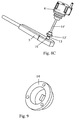
La pièce 14 de transmission du mouvement entre le moteur inférieur 8 et l'axe de commande extérieur 13 présente une région centrale dégagée (selon la direction axiale des deux moteurs à l'état monté), et est muni au niveau de son fond d'une découpe carrée pour un engagement ajusté sur l'axe extérieur 13 et au niveau de sa partie supérieure de sites d'engagement avec la bride de sortie du moteur inférieur 8 à axe creux (par exemple liaison du type ergots/orifices).The
Comme le montre notamment la
Le moteur supérieur 8' est maintenu en alignement axial avec le moteur inférieur 8 et les axes de commande 13 et 13' par l'intermédiaire de la pièce support additionnelle 15'.The upper motor 8 'is maintained in axial alignment with the
Selon une variante non représentée et ne faisant pas partie de l'invention, les moyens actionneurs 8, 8' peuvent aussi se présenter sous la forme de moteurs directement logés dans la poignée formant le moyen de commande 5 et en relation d'entraînement chacun avec un câble de commande de la déformation par flexion du segment d'extrémité 3.According to a variant not shown and not forming part of the invention, the actuator means 8, 8 'can also be in the form of motors directly housed in the handle forming the control means 5 and in driving relation each with a cable for controlling the bending deformation of the
Dans le cadre de cette dernière variante, le moyen de commande 5 peut également comporter au moins un organe manipulable par le praticien, tel qu'une molette, une manette ou analogue, apte à commander au moins un actionneur 8, 8', ce de manière alternative ou superposée par rapport à la commande automatique par asservissement visuel, ledit ou lesdits organe(s) étant soi(en)t monté(s) au niveau de la poignée 5, soit déporté(s) par rapport à cette dernière.In the context of this latter variant, the control means 5 may also comprise at least one member that can be manipulated by the practitioner, such as a thumbwheel, a joystick or the like, able to control at least one
Ainsi, il est possible de disposer d'une commande manuelle assistée, qui peut être superposée à la commande automatique par asservissement visuel ou fonctionner de manière découplée par rapport à cette dernière.Thus, it is possible to have an assisted manual control, which can be superimposed on the automatic control by visual servoing or operate decoupled from it.
Dans le cas de la mise en oeuvre de molettes embarquées sur la poignée 5, le praticien retrouvera la configuration de manipulation actuelle, tout en bénéficiant des avantages de l'invention.In the case of the implementation of wheels embedded on the
Un exemple de procédé de stabilisation d'un endoscope flexible par asservissement visuel est décrit ci-après.An example of a method of stabilizing a flexible endoscope by visual servoing is described below.
Ce procédé met en oeuvre un dispositif 1 d'endoscope flexible comprenant essentiellement un corps souple allongé 2 présentant un segment d'extrémité flexible 3 portant ou fonnant la tête 3' de l'endoscope, muni d'un système optique 4 et pouvant être courbé ou fléchi selon au moins deux directions mutuellement perpendiculaires, ledit corps allongé 2 étant relié fonctionnellement, à son autre extrémité (opposée ou segment 3), à un moyen de commande 5 apte à contrôler au moins les mouvements et/ou la disposition dudit segment d'extrémité, plus particulièrement un dispositif tel que décrit précédemment.This method implements a
Ce procédé consiste à réaliser automatiquement, par l'intermédiaire de moyens 6, 7, 8 et 8' de flexion et de positionnement automatiques du segment d'extrémité 3 organisé fonctionnellement en au moins une boucle d'asservissement 9, un traitement des images fournies par le système optique 4 de la tête 3' de l'endoscope, des opérations d'asservissement visuel sur la base des signaux vidéo traités et l'élaboration et la fourniture de signaux de commande à des moyens actionneurs 8, 8' faisant partie ou associés au moyen de commande 5.This method consists in automatically performing, by means of
Les opérations d'asservissement consistent essentiellement à minimiser l'erreur ou une mesure de dissemblance analogue entre, d'une part, un élément visuel ou d'information visuelle cible extrait d'une image de référence 10 et, d'autre part, un élément visuel ou d'information visuelle correspondant extrait de l'image courante 10' fournie par le système optique 4 de la tête de l'endoscope 3', ladite erreur étant exploitée pour délivrer des signaux de commande au(x) moyen(s) actionneur(s) 8, 8' contrôlant les mouvements et le positionnement dudit segment d'extrémité 3 selon au moins une direction.The servo-control operations essentially consist in minimizing the error or a similar measure of dissimilarity between, on the one hand, a target visual or visual information element extracted from a
Préférentiellement, les éléments visuels ou d'information visuelle sont choisis dans le groupe formé par les motifs visuels, les réductions d'image et les parties ou zones d'image obtenues respectivement à partir de l'image de référence 10 et de l'image courante 10' fournie par le système optique 4, le cas échéant après traitement adapté de celles-ci.Preferably, the visual or visual information elements are chosen from the group formed by the visual patterns, the image reductions and the image portions or zones respectively obtained from the
Conformément à un mode de réalisation avantageux, le procédé consiste, dans le cadres des opérations d'asservissement réalisées par le moyen informatique 7, à déterminer en temps réel, c'est-à-dire au moins à la vitesse de fourniture des images vidéo, une approximation, préférentiellement par un traitement itératif, de la transformation à appliquer à l'image courante 10' aboutissant à une minimisation d'une fonction de coût entre une image réduite ou imagette T* obtenue à partir de l'image de référence 10 et une image réduite ou imagette T obtenue à partir de l'image de référence 10' fournie par la tête 3' de l'endoscope et traitée par la transformation approximée courante.According to an advantageous embodiment, the method consists, in the context of servocontrol operations carried out by the computer means 7, to determine in real time, that is to say at least at the speed of supply of the video images. , an approximation, preferably by iterative processing, of the transformation to be applied to the current image 10 'resulting in a minimization of a cost function between a reduced or an imaginary image T * obtained from the
Selon une première variante du procédé, ce dernier peut consister à mettre en oeuvre un algorithme de minimisation réalisant une minimisation paramétrique de l'erreur quadratique entre les éléments visuels ou d'information visuelle T* et T obtenus respectivement à partir de l'image de référence 10 et à partir de l'image courante 10', la transformation approximée étant une transformation de plan, par exemple, de type homo graphique.According to a first variant of the method, the latter can consist in implementing a minimization algorithm performing a parametric minimization of the quadratic error between the visual or visual information elements T * and T respectively obtained from the image of
Selon une seconde variante du procédé, ce dernier peut consister à mettre en oeuvre un algorithme de minimisation réalisant une minimisation statistique d'une mesure de dissemblance entre des histogrammes obtenus à partir des éléments visuels ou d'information visuelle T* et T obtenus respectivement à partir de l'image de référence 10 et à partir de l'image courante 10', la transformation approximée étant composée d'une translation dans le plan image et d'un zoom.According to a second variant of the method, the latter can consist in implementing a minimization algorithm achieving a statistical minimization of a measure of dissimilarity between histograms obtained from the visual elements or visual information T * and T respectively obtained at from the
Avantageusement, il est prévu que les mouvements et le positionnement du segment d'extrémité 3' sont contrôlés par deux actionneurs indépendants 8 et 8' associés chacun à l'une de deux directions perpendiculaires correspondant à deux directions de l'image courante plane 10' fournie de manière répétée par la tête de l'endoscope 3'.Advantageously, it is provided that the movements and positioning of the end segment 3 'are controlled by two
En relation avec la
La phase de paramétrage peut consister, pour le praticien, à déterminer la consigne sref de la boucle d'asservissement 9, sous la forme d'indices visuels adéquats (par exemple coordonnées x, y d'un point) sélectionnés dans une image de référence 10, en vue de contrôler les différents degrés de liberté de l'endoscope flexible, en particulier de son extrémité libre 3.The parameterization phase may consist, for the practitioner, in determining the reference s ref of the
Puis, la phase de régulation automatique peut consister à répéter de manière cyclique, les étapes suivantes :
- a) extraction dans l'image courante 10' des indices visuels s courant correspondant aux indices visuel(s) sref formant la consigne et sélectionnés dans l'image de référence 10 ;
- b) calcul de l'erreur e = s - sref ;
- c) calcul des signaux de commande à appliquer aux actionneurs 8 et 8', notamment des signaux de vitesse, pour faire diminuer l'erreur e ;
- d) envoi des signaux de commande ;
- e) acquisition d'une nouvelle image courante 10' par l'intermédiaire du système optique et éventuel traitement de cette image ;
- f) retour à l'étape a).
- a) extraction in the current image 10 'of visual cues current corresponding to the visual cues (s) ref forming the setpoint and selected in the
reference image 10; - b) calculation of the error e = s - s ref ;
- c) calculation of the control signals to be applied to the
actuators 8 and 8 ', in particular speed signals, to reduce the error e; - d) sending control signals;
- e) acquisition of a new current image 10 'via the optical system and possible treatment of this image;
- f) return to step a).
Afin de rendre l'asservissement plus robuste et de rendre plus efficace la détection de la cible, il peut en outre être prévu de mettre en place préalablement un repère artificiel à proximité immédiate de la cible anatomique.In order to make the servocontrol more robust and to make the detection of the target more effective, it may also be planned to set up an artificial marker in the immediate vicinity of the anatomical target.
Un exemple de mise en oeuvre pratique de l'invention, ainsi que les avantages procurés par celle-ci, sont décrits dans la publication suivante : "
Bien entendu, l'invention n'est pas limitée au mode de réalisation décrit et représenté aux dessins annexés. Des modifications restent possibles, notamment du point de vue de la constitution des divers éléments ou par substitution d'équivalents techniques, sans sortir pour autant du domaine de protection defini par les revendications.Of course, the invention is not limited to the embodiment described and shown in the accompanying drawings. Modifications are possible, particularly from the point of view of the constitution of the various elements or by substitution of technical equivalents, without departing from the scope of protection defined by the claims.
Claims (8)
- Flexible endoscopic device,
said device (1) comprising an elongated flexible body (2) with a flexible end segment (3) that supports or forms the head of the endoscope, equipped with an optical system (4) and able to be curved or bent in at least two mutually perpendicular directions, said elongated body (2) being connected functionally at its other end to a control means (5) for monitoring at least the movements and/or the arrangement of said end segment,
said device (1) also comprising automatic means for orienting and positioning the end segment (3) by visual servoing, said means essentially consisting of a video processing device (6) receiving video images or signals supplied by the optical system (4) of the head of the endoscope (3') by a computer means (7) that can implement visual servo operations on the basis of processed video signals and providing control signals, and by actuating means (8, 8') that are part of or are associated with a control means (5) for monitoring the end segment (3) and receiving control signals supplied by the computer means (7),
the means (6, 7, 8, 8', 12, 12') for automatically orientating and positioning the end segment (3) being organised functionally to form at least one control loop (9) that is designed to minimise error or an analogous measure of dissimilarity between on the one hand a target visual element or visual information extracted from a reference image (10) and on the other hand a corresponding visual element or visual information extracted from the current image (10') supplied by the optical system (4) of the head of the endoscope (3'), said error being used to deliver control signals to the actuating means (8, 8') monitoring the movements and the positioning of said end segment (3) in at least one direction,
the computer means (7) being able, by executing a suitable program, to determine in real time, i.e. at least at the speed at which video images are supplied, an approximation, preferably by iterative processing, of the transformation to be applied to the current image (10') so as to approach the latter from the reference image,
the automatic positioning means (6, 7, 8, 8') being arranged in a bidimensional visual servo loop and comprising two independent actuators (8 and 8'), each controlling the movements and the positioning of the end segment (3) according to any one of two mutually perpendicular directions corresponding to two directions of the current plane image (10') provided by the head of the endoscope (3'),
the device (1) being characterised in that
the program executed by the computer means (7), within the context of servo operations, implements the approximation by minimising a cost function between a reduced image or thumbnail (T*) obtained from the reference image (10) and a reduced image or thumbnail (T) obtained from the current image (10') supplied by the head (3') of the endoscope and processed by the current approximated transformation,
the reduced images or thumbnail images comprising target visual elements or visual information extracted from reference and current images and
in that the control means (5) comprises two concentric control axes (13 and 13') each connected to a control cable (12, 12') circulating along the elongated body (2) and connected to the end segment (3) to control the bending or the bowing of said segment (3) according to one of two mutually perpendicular bending directions, the external axis (13) being drive-related to a first actuator (8) in the form of a motor with a hollow axis (8") by means of a disengaged transmission part (14) in a central area extending into the continuity of the hollow axis (8") of said motor (8) and the internal axis (13') being in drive relation, by means of an elongated drive part (14') with a second actuator (8') in the form a motor aligned with the first motor (8) according to their axes of rotation, said elongated drive part (14') traversing the first motor (8) at its hollow axis (8"). - Device according to claim 1, characterised in that the visual elements or visual information are selected from a group formed by visual patterns, the reductions of images and parts or zones of images that are obtained respectively from the reference image (10), in the form of an initial image or a base image supplied by the optical system (4) or a real image of the anatomical environment of the target acquired by selection, and the current image (10') supplied by the optical system (4), if necessary after suitable processing of the latter.
- Device according to claim 1 or 2, characterised in that the minimisation algorithm implemented by the computer means (7) produces a parametric minimisation of the quadratic error between the visual elements or visual information (T* and T) obtained respectively from the reference image (10) and from the current image (10'), whereby the approximated transformation is a plane transformation, for example, of the homographic type.
- Device according to claim 1 or 2, characterised in that the minimisation algorithm implemented by the computer means (7) produces a statistical minimisation of a measure of dissimilarity between histograms that are obtained from visual elements or visual information (T* and T) obtained respectively from the reference image (10) and from the current image (10'), whereby the approximated transformation consists of a translation in the image plane and a zoom.
- Device according to claim 1 to 4, characterised in that an independent servo loop is provided for each actuating means (8, 8').
- Device according to any one of claims 1 to 5, characterised in that the monitor or corrector (11) that is part of the servo loop (9) is selected from a group formed by monitors of the proportional type, of the proportional/integral/derivative type, and of the predictive or repetitive type.
- Device according to any one of claims 1 to 6, characterised in that the two motors (8 and 8') are assembled mechanically with one another to form a drive system unit that is mounted on the handle (5) that forms the control means, by means of a support and attaching part (15), if necessary in the form of a unit with a removable mechanical connection.
- Device according to claim 7, characterised in that it comprises at least one element that can be manipulated by a practitioner, such as a roller, a lever or the like, able to control at least one actuator (8, 8') in an alternative or superimposed manner relative to the automatic command by visual servoing, whereby said element is either mounted on the handle (5) or offset relative to the latter.
Applications Claiming Priority (2)
| Application Number | Priority Date | Filing Date | Title |
|---|---|---|---|
| US90286207P | 2007-02-23 | 2007-02-23 | |
| PCT/FR2008/050312 WO2008113957A1 (en) | 2007-02-23 | 2008-02-25 | Flexible endoscope device with visual control and method for stabilising such device |
Publications (2)
| Publication Number | Publication Date |
|---|---|
| EP2124709A1 EP2124709A1 (en) | 2009-12-02 |
| EP2124709B1 true EP2124709B1 (en) | 2016-08-31 |
Family
ID=39676170
Family Applications (1)
| Application Number | Title | Priority Date | Filing Date |
|---|---|---|---|
| EP08762153.8A Not-in-force EP2124709B1 (en) | 2007-02-23 | 2008-02-25 | Flexible endoscope device with visual control |
Country Status (4)
| Country | Link |
|---|---|
| US (1) | US20100168518A1 (en) |
| EP (1) | EP2124709B1 (en) |
| JP (1) | JP2010518954A (en) |
| WO (1) | WO2008113957A1 (en) |
Families Citing this family (4)
| Publication number | Priority date | Publication date | Assignee | Title |
|---|---|---|---|---|
| DE102008018723B3 (en) * | 2008-04-14 | 2009-07-16 | Siemens Aktiengesellschaft | Method for controlling the movement of an endoscopy capsule |
| US8934003B2 (en) * | 2010-01-08 | 2015-01-13 | Koninklijkle Philips N.V. | Uncalibrated visual servoing using real-time velocity optimization |
| US10299773B2 (en) * | 2011-08-21 | 2019-05-28 | Transenterix Europe S.A.R.L. | Device and method for assisting laparoscopic surgery—rule based approach |
| AU2014231345B2 (en) | 2013-03-15 | 2019-01-17 | Synaptive Medical Inc. | Intelligent positioning system and methods therefore |
Citations (2)
| Publication number | Priority date | Publication date | Assignee | Title |
|---|---|---|---|---|
| US5906578A (en) * | 1997-06-18 | 1999-05-25 | Rajan; Govinda N. | Method and system for probe positioning in transesophageal echocardiography |
| US20040097789A1 (en) * | 2002-11-18 | 2004-05-20 | Weinberg Andrew Mark | Colonoscope apparatus and method |
Family Cites Families (7)
| Publication number | Priority date | Publication date | Assignee | Title |
|---|---|---|---|---|
| US5347987A (en) * | 1991-04-08 | 1994-09-20 | Feldstein David A | Self-centering endoscope system |
| DE19529950C1 (en) * | 1995-08-14 | 1996-11-14 | Deutsche Forsch Luft Raumfahrt | Guiding method for stereo laparoscope in minimal invasive surgery |
| US5951461A (en) * | 1996-12-20 | 1999-09-14 | Nyo; Tin | Image-guided laryngoscope for tracheal intubation |
| AU2002253784A1 (en) * | 2000-11-07 | 2002-08-28 | Hypermed, Inc. | Hyperspectral imaging calibration device |
| US6695774B2 (en) * | 2001-01-19 | 2004-02-24 | Endactive, Inc. | Apparatus and method for controlling endoscopic instruments |
| US8721655B2 (en) * | 2002-04-10 | 2014-05-13 | Stereotaxis, Inc. | Efficient closed loop feedback navigation |
| JP3973504B2 (en) * | 2002-07-15 | 2007-09-12 | 株式会社日立製作所 | Tow positioning device |
-
2008
- 2008-02-25 EP EP08762153.8A patent/EP2124709B1/en not_active Not-in-force
- 2008-02-25 WO PCT/FR2008/050312 patent/WO2008113957A1/en active Application Filing
- 2008-02-25 US US12/528,254 patent/US20100168518A1/en not_active Abandoned
- 2008-02-25 JP JP2009550745A patent/JP2010518954A/en not_active Withdrawn
Patent Citations (2)
| Publication number | Priority date | Publication date | Assignee | Title |
|---|---|---|---|---|
| US5906578A (en) * | 1997-06-18 | 1999-05-25 | Rajan; Govinda N. | Method and system for probe positioning in transesophageal echocardiography |
| US20040097789A1 (en) * | 2002-11-18 | 2004-05-20 | Weinberg Andrew Mark | Colonoscope apparatus and method |
Also Published As
| Publication number | Publication date |
|---|---|
| WO2008113957A1 (en) | 2008-09-25 |
| EP2124709A1 (en) | 2009-12-02 |
| JP2010518954A (en) | 2010-06-03 |
| US20100168518A1 (en) | 2010-07-01 |
Similar Documents
| Publication | Publication Date | Title |
|---|---|---|
| US11000339B2 (en) | System and apparatus for positioning an instrument in a body cavity for performing a surgical procedure | |
| US20180344134A1 (en) | Surgeon controlled endoscope device and method | |
| EP2306911B1 (en) | Modular surgical tool | |
| CN111632251B (en) | Catheter system | |
| JP6310455B2 (en) | Controller definition for robot remote motion center | |
| CN106236277B (en) | The application of force feedback on input unit promotes its operator's order articulated type instrument to be put into preferred posture | |
| US9020613B2 (en) | Method and apparatus for robotically assisted cochlear implant surgery | |
| EP2092874B1 (en) | Manipulator operation system | |
| US20220168054A1 (en) | Guide apparatus for delivery of a flexible instrument and methods of use | |
| CN111655115A (en) | Virtual reality surgical camera system | |
| JP2017525499A (en) | System and method for medical device force detection | |
| KR20120014242A (en) | System for providing visual guidance for steering a tip of an endoscopic device towards one or more landmarks and assisting an operator in endoscopic navigation | |
| CN103607941A (en) | Medical system with multiple operating modes for steering a medical instrument through linked body passages | |
| Saeidi et al. | Autonomous laparoscopic robotic suturing with a novel actuated suturing tool and 3D endoscope | |
| EP2124709B1 (en) | Flexible endoscope device with visual control | |
| EP3272269B1 (en) | Surgeon controlled endoscope device and method | |
| WO2023039931A1 (en) | Control device for flexible surgical instrument, and endoscopic surgical robot system | |
| KR20210010495A (en) | Backend mechanism of catheter control system | |
| US20220079696A1 (en) | Systems for coupling and storing an imaging instrument | |
| US20210186307A1 (en) | Endoscope with detachable camera module | |
| CN117297773A (en) | Surgical instrument control method, surgical robot, and storage medium | |
| FR3132832A1 (en) | Robotic spinal surgery system | |
| US20230310807A1 (en) | Instrument with a counter-pivoting mechanism | |
| JP6531174B2 (en) | Endoscopic surgery apparatus and guide apparatus |
Legal Events
| Date | Code | Title | Description |
|---|---|---|---|
| PUAI | Public reference made under article 153(3) epc to a published international application that has entered the european phase |
Free format text: ORIGINAL CODE: 0009012 |
|
| 17P | Request for examination filed |
Effective date: 20090922 |
|
| AK | Designated contracting states |
Kind code of ref document: A1 Designated state(s): AT BE BG CH CY CZ DE DK EE ES FI FR GB GR HR HU IE IS IT LI LT LU LV MC MT NL NO PL PT RO SE SI SK TR |
|
| DAX | Request for extension of the european patent (deleted) | ||
| 17Q | First examination report despatched |
Effective date: 20140212 |
|
| GRAP | Despatch of communication of intention to grant a patent |
Free format text: ORIGINAL CODE: EPIDOSNIGR1 |
|
| INTG | Intention to grant announced |
Effective date: 20160322 |
|
| RAP1 | Party data changed (applicant data changed or rights of an application transferred) |
Owner name: UNIVERSITE DE STRASBOURG (ETABLISSEMENT PUBLIC A C Owner name: CENTRE NATIONAL DE LA RECHERCHE SCIENTIFIQUE |
|
| RIN1 | Information on inventor provided before grant (corrected) |
Inventor name: OTT, LAURENT Inventor name: DE MATHELIN, MICHEL Inventor name: GANGLOFF, JACQUES Inventor name: ZANNE, PHILIPPE |
|
| GRAS | Grant fee paid |
Free format text: ORIGINAL CODE: EPIDOSNIGR3 |
|
| GRAA | (expected) grant |
Free format text: ORIGINAL CODE: 0009210 |
|
| AK | Designated contracting states |
Kind code of ref document: B1 Designated state(s): AT BE BG CH CY CZ DE DK EE ES FI FR GB GR HR HU IE IS IT LI LT LU LV MC MT NL NO PL PT RO SE SI SK TR |
|
| REG | Reference to a national code |
Ref country code: CH Ref legal event code: EP Ref country code: GB Ref legal event code: FG4D Free format text: NOT ENGLISH |
|
| REG | Reference to a national code |
Ref country code: IE Ref legal event code: FG4D Free format text: LANGUAGE OF EP DOCUMENT: FRENCH |
|
| REG | Reference to a national code |
Ref country code: DE Ref legal event code: R096 Ref document number: 602008046002 Country of ref document: DE |
|
| REG | Reference to a national code |
Ref country code: AT Ref legal event code: REF Ref document number: 824209 Country of ref document: AT Kind code of ref document: T Effective date: 20161015 |
|
| REG | Reference to a national code |
Ref country code: LT Ref legal event code: MG4D |
|
| REG | Reference to a national code |
Ref country code: NL Ref legal event code: MP Effective date: 20160831 |
|
| REG | Reference to a national code |
Ref country code: AT Ref legal event code: MK05 Ref document number: 824209 Country of ref document: AT Kind code of ref document: T Effective date: 20160831 |
|
| REG | Reference to a national code |
Ref country code: FR Ref legal event code: PLFP Year of fee payment: 10 |
|
| PG25 | Lapsed in a contracting state [announced via postgrant information from national office to epo] |
Ref country code: HR Free format text: LAPSE BECAUSE OF FAILURE TO SUBMIT A TRANSLATION OF THE DESCRIPTION OR TO PAY THE FEE WITHIN THE PRESCRIBED TIME-LIMIT Effective date: 20160831 Ref country code: NO Free format text: LAPSE BECAUSE OF FAILURE TO SUBMIT A TRANSLATION OF THE DESCRIPTION OR TO PAY THE FEE WITHIN THE PRESCRIBED TIME-LIMIT Effective date: 20161130 Ref country code: FI Free format text: LAPSE BECAUSE OF FAILURE TO SUBMIT A TRANSLATION OF THE DESCRIPTION OR TO PAY THE FEE WITHIN THE PRESCRIBED TIME-LIMIT Effective date: 20160831 Ref country code: LT Free format text: LAPSE BECAUSE OF FAILURE TO SUBMIT A TRANSLATION OF THE DESCRIPTION OR TO PAY THE FEE WITHIN THE PRESCRIBED TIME-LIMIT Effective date: 20160831 |
|
| PG25 | Lapsed in a contracting state [announced via postgrant information from national office to epo] |
Ref country code: SE Free format text: LAPSE BECAUSE OF FAILURE TO SUBMIT A TRANSLATION OF THE DESCRIPTION OR TO PAY THE FEE WITHIN THE PRESCRIBED TIME-LIMIT Effective date: 20160831 Ref country code: ES Free format text: LAPSE BECAUSE OF FAILURE TO SUBMIT A TRANSLATION OF THE DESCRIPTION OR TO PAY THE FEE WITHIN THE PRESCRIBED TIME-LIMIT Effective date: 20160831 Ref country code: GR Free format text: LAPSE BECAUSE OF FAILURE TO SUBMIT A TRANSLATION OF THE DESCRIPTION OR TO PAY THE FEE WITHIN THE PRESCRIBED TIME-LIMIT Effective date: 20161201 Ref country code: AT Free format text: LAPSE BECAUSE OF FAILURE TO SUBMIT A TRANSLATION OF THE DESCRIPTION OR TO PAY THE FEE WITHIN THE PRESCRIBED TIME-LIMIT Effective date: 20160831 Ref country code: NL Free format text: LAPSE BECAUSE OF FAILURE TO SUBMIT A TRANSLATION OF THE DESCRIPTION OR TO PAY THE FEE WITHIN THE PRESCRIBED TIME-LIMIT Effective date: 20160831 Ref country code: LV Free format text: LAPSE BECAUSE OF FAILURE TO SUBMIT A TRANSLATION OF THE DESCRIPTION OR TO PAY THE FEE WITHIN THE PRESCRIBED TIME-LIMIT Effective date: 20160831 |
|
| PG25 | Lapsed in a contracting state [announced via postgrant information from national office to epo] |
Ref country code: EE Free format text: LAPSE BECAUSE OF FAILURE TO SUBMIT A TRANSLATION OF THE DESCRIPTION OR TO PAY THE FEE WITHIN THE PRESCRIBED TIME-LIMIT Effective date: 20160831 Ref country code: RO Free format text: LAPSE BECAUSE OF FAILURE TO SUBMIT A TRANSLATION OF THE DESCRIPTION OR TO PAY THE FEE WITHIN THE PRESCRIBED TIME-LIMIT Effective date: 20160831 |
|
| PG25 | Lapsed in a contracting state [announced via postgrant information from national office to epo] |
Ref country code: DK Free format text: LAPSE BECAUSE OF FAILURE TO SUBMIT A TRANSLATION OF THE DESCRIPTION OR TO PAY THE FEE WITHIN THE PRESCRIBED TIME-LIMIT Effective date: 20160831 Ref country code: CZ Free format text: LAPSE BECAUSE OF FAILURE TO SUBMIT A TRANSLATION OF THE DESCRIPTION OR TO PAY THE FEE WITHIN THE PRESCRIBED TIME-LIMIT Effective date: 20160831 Ref country code: BE Free format text: LAPSE BECAUSE OF NON-PAYMENT OF DUE FEES Effective date: 20170228 Ref country code: SK Free format text: LAPSE BECAUSE OF FAILURE TO SUBMIT A TRANSLATION OF THE DESCRIPTION OR TO PAY THE FEE WITHIN THE PRESCRIBED TIME-LIMIT Effective date: 20160831 Ref country code: BG Free format text: LAPSE BECAUSE OF FAILURE TO SUBMIT A TRANSLATION OF THE DESCRIPTION OR TO PAY THE FEE WITHIN THE PRESCRIBED TIME-LIMIT Effective date: 20161130 Ref country code: PT Free format text: LAPSE BECAUSE OF FAILURE TO SUBMIT A TRANSLATION OF THE DESCRIPTION OR TO PAY THE FEE WITHIN THE PRESCRIBED TIME-LIMIT Effective date: 20170102 Ref country code: PL Free format text: LAPSE BECAUSE OF FAILURE TO SUBMIT A TRANSLATION OF THE DESCRIPTION OR TO PAY THE FEE WITHIN THE PRESCRIBED TIME-LIMIT Effective date: 20160831 |
|
| PGFP | Annual fee paid to national office [announced via postgrant information from national office to epo] |
Ref country code: GB Payment date: 20170209 Year of fee payment: 10 |
|
| REG | Reference to a national code |
Ref country code: DE Ref legal event code: R097 Ref document number: 602008046002 Country of ref document: DE |
|
| PG25 | Lapsed in a contracting state [announced via postgrant information from national office to epo] |
Ref country code: IT Free format text: LAPSE BECAUSE OF FAILURE TO SUBMIT A TRANSLATION OF THE DESCRIPTION OR TO PAY THE FEE WITHIN THE PRESCRIBED TIME-LIMIT Effective date: 20160831 |
|
| PLBE | No opposition filed within time limit |
Free format text: ORIGINAL CODE: 0009261 |
|
| STAA | Information on the status of an ep patent application or granted ep patent |
Free format text: STATUS: NO OPPOSITION FILED WITHIN TIME LIMIT |
|
| 26N | No opposition filed |
Effective date: 20170601 |
|
| PG25 | Lapsed in a contracting state [announced via postgrant information from national office to epo] |
Ref country code: SI Free format text: LAPSE BECAUSE OF FAILURE TO SUBMIT A TRANSLATION OF THE DESCRIPTION OR TO PAY THE FEE WITHIN THE PRESCRIBED TIME-LIMIT Effective date: 20160831 |
|
| PG25 | Lapsed in a contracting state [announced via postgrant information from national office to epo] |
Ref country code: MC Free format text: LAPSE BECAUSE OF FAILURE TO SUBMIT A TRANSLATION OF THE DESCRIPTION OR TO PAY THE FEE WITHIN THE PRESCRIBED TIME-LIMIT Effective date: 20160831 |
|
| REG | Reference to a national code |
Ref country code: CH Ref legal event code: PL |
|
| PG25 | Lapsed in a contracting state [announced via postgrant information from national office to epo] |
Ref country code: LI Free format text: LAPSE BECAUSE OF NON-PAYMENT OF DUE FEES Effective date: 20170228 Ref country code: CH Free format text: LAPSE BECAUSE OF NON-PAYMENT OF DUE FEES Effective date: 20170228 |
|
| REG | Reference to a national code |
Ref country code: IE Ref legal event code: MM4A |
|
| PG25 | Lapsed in a contracting state [announced via postgrant information from national office to epo] |
Ref country code: LU Free format text: LAPSE BECAUSE OF NON-PAYMENT OF DUE FEES Effective date: 20170225 |
|
| REG | Reference to a national code |
Ref country code: BE Ref legal event code: MM Effective date: 20170228 |
|
| PG25 | Lapsed in a contracting state [announced via postgrant information from national office to epo] |
Ref country code: IE Free format text: LAPSE BECAUSE OF NON-PAYMENT OF DUE FEES Effective date: 20170225 |
|
| REG | Reference to a national code |
Ref country code: FR Ref legal event code: PLFP Year of fee payment: 11 |
|
| PG25 | Lapsed in a contracting state [announced via postgrant information from national office to epo] |
Ref country code: MT Free format text: LAPSE BECAUSE OF FAILURE TO SUBMIT A TRANSLATION OF THE DESCRIPTION OR TO PAY THE FEE WITHIN THE PRESCRIBED TIME-LIMIT Effective date: 20160831 |
|
| GBPC | Gb: european patent ceased through non-payment of renewal fee |
Effective date: 20180225 |
|
| PG25 | Lapsed in a contracting state [announced via postgrant information from national office to epo] |
Ref country code: GB Free format text: LAPSE BECAUSE OF NON-PAYMENT OF DUE FEES Effective date: 20180225 |
|
| PG25 | Lapsed in a contracting state [announced via postgrant information from national office to epo] |
Ref country code: HU Free format text: LAPSE BECAUSE OF FAILURE TO SUBMIT A TRANSLATION OF THE DESCRIPTION OR TO PAY THE FEE WITHIN THE PRESCRIBED TIME-LIMIT; INVALID AB INITIO Effective date: 20080225 |
|
| PG25 | Lapsed in a contracting state [announced via postgrant information from national office to epo] |
Ref country code: CY Free format text: LAPSE BECAUSE OF NON-PAYMENT OF DUE FEES Effective date: 20160831 |
|
| PG25 | Lapsed in a contracting state [announced via postgrant information from national office to epo] |
Ref country code: TR Free format text: LAPSE BECAUSE OF FAILURE TO SUBMIT A TRANSLATION OF THE DESCRIPTION OR TO PAY THE FEE WITHIN THE PRESCRIBED TIME-LIMIT Effective date: 20160831 |
|
| PG25 | Lapsed in a contracting state [announced via postgrant information from national office to epo] |
Ref country code: IS Free format text: LAPSE BECAUSE OF FAILURE TO SUBMIT A TRANSLATION OF THE DESCRIPTION OR TO PAY THE FEE WITHIN THE PRESCRIBED TIME-LIMIT Effective date: 20161231 |
|
| PGFP | Annual fee paid to national office [announced via postgrant information from national office to epo] |
Ref country code: FR Payment date: 20210226 Year of fee payment: 14 |
|
| PGFP | Annual fee paid to national office [announced via postgrant information from national office to epo] |
Ref country code: DE Payment date: 20210226 Year of fee payment: 14 |
|
| REG | Reference to a national code |
Ref country code: DE Ref legal event code: R119 Ref document number: 602008046002 Country of ref document: DE |
|
| PG25 | Lapsed in a contracting state [announced via postgrant information from national office to epo] |
Ref country code: FR Free format text: LAPSE BECAUSE OF NON-PAYMENT OF DUE FEES Effective date: 20220228 |
|
| PG25 | Lapsed in a contracting state [announced via postgrant information from national office to epo] |
Ref country code: DE Free format text: LAPSE BECAUSE OF NON-PAYMENT OF DUE FEES Effective date: 20220901 |