EP2115296B1 - Control of a plurality of plug coils via a single power stage - Google Patents
Control of a plurality of plug coils via a single power stage Download PDFInfo
- Publication number
- EP2115296B1 EP2115296B1 EP08762151.2A EP08762151A EP2115296B1 EP 2115296 B1 EP2115296 B1 EP 2115296B1 EP 08762151 A EP08762151 A EP 08762151A EP 2115296 B1 EP2115296 B1 EP 2115296B1
- Authority
- EP
- European Patent Office
- Prior art keywords
- frequency
- plasma generation
- resonator
- circuit
- power supply
- Prior art date
- Legal status (The legal status is an assumption and is not a legal conclusion. Google has not performed a legal analysis and makes no representation as to the accuracy of the status listed.)
- Not-in-force
Links
- 238000002485 combustion reaction Methods 0.000 claims description 11
- 238000000034 method Methods 0.000 claims description 6
- 238000004378 air conditioning Methods 0.000 claims description 3
- 238000005202 decontamination Methods 0.000 claims description 3
- 230000003588 decontaminative effect Effects 0.000 claims description 3
- 239000002245 particle Substances 0.000 claims description 3
- 238000012546 transfer Methods 0.000 description 5
- 238000004519 manufacturing process Methods 0.000 description 4
- 238000005259 measurement Methods 0.000 description 4
- 230000003321 amplification Effects 0.000 description 3
- 239000003990 capacitor Substances 0.000 description 3
- 238000010586 diagram Methods 0.000 description 3
- 238000003199 nucleic acid amplification method Methods 0.000 description 3
- 238000009434 installation Methods 0.000 description 2
- 230000006978 adaptation Effects 0.000 description 1
- 238000010276 construction Methods 0.000 description 1
- 238000011161 development Methods 0.000 description 1
- 230000000694 effects Effects 0.000 description 1
- 230000006870 function Effects 0.000 description 1
- 239000008246 gaseous mixture Substances 0.000 description 1
- 238000003780 insertion Methods 0.000 description 1
- 230000037431 insertion Effects 0.000 description 1
- 230000010354 integration Effects 0.000 description 1
- 239000000203 mixture Substances 0.000 description 1
- 239000010705 motor oil Substances 0.000 description 1
Images
Classifications
-
- F—MECHANICAL ENGINEERING; LIGHTING; HEATING; WEAPONS; BLASTING
- F02—COMBUSTION ENGINES; HOT-GAS OR COMBUSTION-PRODUCT ENGINE PLANTS
- F02P—IGNITION, OTHER THAN COMPRESSION IGNITION, FOR INTERNAL-COMBUSTION ENGINES; TESTING OF IGNITION TIMING IN COMPRESSION-IGNITION ENGINES
- F02P9/00—Electric spark ignition control, not otherwise provided for
- F02P9/002—Control of spark intensity, intensifying, lengthening, suppression
- F02P9/007—Control of spark intensity, intensifying, lengthening, suppression by supplementary electrical discharge in the pre-ionised electrode interspace of the sparking plug, e.g. plasma jet ignition
-
- F—MECHANICAL ENGINEERING; LIGHTING; HEATING; WEAPONS; BLASTING
- F02—COMBUSTION ENGINES; HOT-GAS OR COMBUSTION-PRODUCT ENGINE PLANTS
- F02P—IGNITION, OTHER THAN COMPRESSION IGNITION, FOR INTERNAL-COMBUSTION ENGINES; TESTING OF IGNITION TIMING IN COMPRESSION-IGNITION ENGINES
- F02P17/00—Testing of ignition installations, e.g. in combination with adjusting; Testing of ignition timing in compression-ignition engines
- F02P17/12—Testing characteristics of the spark, ignition voltage or current
-
- F—MECHANICAL ENGINEERING; LIGHTING; HEATING; WEAPONS; BLASTING
- F02—COMBUSTION ENGINES; HOT-GAS OR COMBUSTION-PRODUCT ENGINE PLANTS
- F02P—IGNITION, OTHER THAN COMPRESSION IGNITION, FOR INTERNAL-COMBUSTION ENGINES; TESTING OF IGNITION TIMING IN COMPRESSION-IGNITION ENGINES
- F02P23/00—Other ignition
- F02P23/04—Other physical ignition means, e.g. using laser rays
-
- F—MECHANICAL ENGINEERING; LIGHTING; HEATING; WEAPONS; BLASTING
- F02—COMBUSTION ENGINES; HOT-GAS OR COMBUSTION-PRODUCT ENGINE PLANTS
- F02P—IGNITION, OTHER THAN COMPRESSION IGNITION, FOR INTERNAL-COMBUSTION ENGINES; TESTING OF IGNITION TIMING IN COMPRESSION-IGNITION ENGINES
- F02P7/00—Arrangements of distributors, circuit-makers or -breakers, e.g. of distributor and circuit-breaker combinations or pick-up devices
- F02P7/02—Arrangements of distributors, circuit-makers or -breakers, e.g. of distributor and circuit-breaker combinations or pick-up devices of distributors
-
- F—MECHANICAL ENGINEERING; LIGHTING; HEATING; WEAPONS; BLASTING
- F02—COMBUSTION ENGINES; HOT-GAS OR COMBUSTION-PRODUCT ENGINE PLANTS
- F02P—IGNITION, OTHER THAN COMPRESSION IGNITION, FOR INTERNAL-COMBUSTION ENGINES; TESTING OF IGNITION TIMING IN COMPRESSION-IGNITION ENGINES
- F02P23/00—Other ignition
- F02P23/04—Other physical ignition means, e.g. using laser rays
- F02P23/045—Other physical ignition means, e.g. using laser rays using electromagnetic microwaves
-
- F—MECHANICAL ENGINEERING; LIGHTING; HEATING; WEAPONS; BLASTING
- F02—COMBUSTION ENGINES; HOT-GAS OR COMBUSTION-PRODUCT ENGINE PLANTS
- F02P—IGNITION, OTHER THAN COMPRESSION IGNITION, FOR INTERNAL-COMBUSTION ENGINES; TESTING OF IGNITION TIMING IN COMPRESSION-IGNITION ENGINES
- F02P3/00—Other installations
- F02P3/01—Electric spark ignition installations without subsequent energy storage, i.e. energy supplied by an electrical oscillator
Landscapes
- Engineering & Computer Science (AREA)
- Chemical & Material Sciences (AREA)
- Combustion & Propulsion (AREA)
- Mechanical Engineering (AREA)
- General Engineering & Computer Science (AREA)
- Physics & Mathematics (AREA)
- Plasma & Fusion (AREA)
- Optics & Photonics (AREA)
- Ignition Installations For Internal Combustion Engines (AREA)
- Generation Of Surge Voltage And Current (AREA)
- Amplifiers (AREA)
Description
La présente invention concerne, de façon générale, les systèmes de génération de plasma entre deux électrodes d'une bougie, utilises notamment pour l'allumage radiofréquence commande d'un mélange gazeux dans des chambres de combustion d'un moteur a combustion interne.The present invention relates generally to systems for generating plasma between two electrodes of a spark plug, used in particular for radiofrequency ignition control of a gaseous mixture in combustion chambers of an internal combustion engine.
Pour une telle application à l'allumage automobile à génération de plasma, des circuits de génération de plasma intégrant des bobines-bougies sont utilisées pour générer des décharges multi-filamentaires entre leurs électrodes, permettant d'initier la combustion du mélange dans les chambres de combustion du moteur. La bougie multi étincelles est décrite en détail dans les demandes de brevet suivantes au nom de la demanderesse
Lorsque le résonateur est alimenté par une haute tension à sa fréquence de résonance ![]()
![]()
On parle alors d'étincelles ramifiées, dans la mesure où elles impliquent la génération simultanée d'au moins plusieurs lignes ou chemin d'ionisation dans un volume donné, leurs ramifications étant en outre omnidirectionnelles.These are referred to as branched sparks, insofar as they involve the simultaneous generation of at least several lines or ionization paths in a given volume, their branches being moreover omnidirectional.
Le pilotage de l'alimentation d'une telle bobine-bougie nécessite l'utilisation d'un circuit d'alimentation, capable de générer des impulsions de tension, typiquement de temps de montée de 100 ns, et d'amplitude de l'ordre de 1 kV, à une fréquence prévue pour être très proche de la fréquence de résonance du résonateur radiofréquence de la bobine-bougie. Plus la différence entre la fréquence de résonance du résonateur et la fréquence de fonctionnement du générateur est réduite, plus le coefficient de surtension du résonateur (rapport entre l'amplitude de sa tension de sortie et sa tension d'entrée) est élevé.The control of the supply of such a coil-plug requires the use of a power supply circuit, capable of generating voltage pulses, typically of rise time of 100 ns, and amplitude of the order of 1 kV, at a frequency intended to be very close to the resonant frequency of the radiofrequency resonator of the coil-candle. The greater the difference between the resonance frequency of the resonator and the operating frequency of the generator, the higher the resonator overvoltage coefficient (ratio between the amplitude of its output voltage and its input voltage) is high.
Un tel circuit d'alimentation, détaillé par ailleurs dans la demande de
Selon le mode de réalisation de la
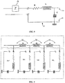
Ainsi, un dispositif de commande 5 génère et applique un signal de commande V1 à une fréquence de commande sur la grille du MOSFET de puissance M, par l'intermédiaire d'un étage de commande 3 représenté schématiquement. Afin de contrôler la production d'étincelles entre les électrodes de la bobine-bougie connectée en sortie de l'amplificateur lorsque son résonateur 1 est excité par l'intermédiaire du signal de commande V1, ce dernier est activé par les différents ordres d'allumage et se présente sous la forme de trains d'impulsions de commande à la fréquence de commande.Thus, a control device 5 generates and applies a control signal V1 to a control frequency on the gate of the power MOSFET M, via a control stage 3 shown schematically. In order to control the production of sparks between the electrodes of the coil-plug connected at the output of the amplifier when its
Comme décrit dans la demande de
A proximité de sa fréquence de résonance, le résonateur parallèle transforme la tension intermédiaire Vinter en une tension amplifiée Va (illustrée à la
Le transistor M agit donc comme un interrupteur et applique (respectivement bloque) la tension Va à l'entrée du résonateur 1 lorsque le signal de commande V1 est à l'état logique haut (respectivement bas). Le transistor M impose ainsi une fréquence de commutation, déterminée par le signal de commande V1, que l'on cherche à rendre la plus proche possible de la fréquence de résonance de la bobine-bougie connectée en sortie (typiquement 5MHz), afin d'entretenir et de maximiser le transfert d'énergie entre le résonateur parallèle 4 et le résonateur série 1 formant la bobine-bougie.The transistor M therefore acts as a switch and applies (respectively blocks) the voltage Va to the input of the
A la fréquence de résonance de la bobine-bougie, on retrouve alors aux bornes de la capacité C du résonateur série 1, soit aux bornes des électrodes de la bougie, la tension de sortie Va précédemment évoquée, multipliée par le coefficient de surtension du résonateur série 1.At the resonance frequency of the coil-plug, then found across the capacitor C of the
Cette phase de transfert d'énergie de l'étage de puissance formée par l'amplificateur vers le résonateur de la bobine-bougie doit être réalisée à la fréquence de résonance du résonateur, pour assurer un bon rendement. En effet, si le transistor M impose une fréquence de commutation différente de la fréquence de résonance de la bobine-bougie, le transfert d'énergie se dégrade, du fait de l'étroitesse de la bande passante du résonateur série utilisé pour la bobine bougie.This phase of energy transfer from the power stage formed by the amplifier to the resonator of the coil-plug must be performed at the resonance frequency of the resonator, to ensure a good performance. Indeed, if the transistor M imposes a different switching frequency of the resonant frequency of the coil-candle, the energy transfer is degraded, because of the narrow bandwidth of the series resonator used for the candle coil .
Dans une application à l'allumage automobile à génération de plasma, chaque chambre de combustion est équipée d'une bobine-bougie comme décrite précédemment afin d'initier, sur commande, la combustion.In an automotive ignition application plasma generation, each combustion chamber is equipped with a coil-candle as described above to initiate, on command, combustion.
En conséquence, pour les moteurs 4 cylindres par exemple, il faut pouvoir disposer de quatre circuits d'alimentation du type amplificateur classe E, comme décrits précédemment en référence à la
Une telle configuration reposant donc sur autant de voies d'amplification qu'il y a de bobines-bougies à commander limite alors le potentiel de développement de ce type d'allumage automobile par génération de plasma, d'une part à cause de l'encombrement provoqué par cette installation sous le capot moteur, mais également, à cause du coût d'installation, qui peut se révéler inabordable pour envisager d'installer ce type d'allumage sur des véhicules de série.Such a configuration thus relying on as many amplification channels as there are spark plugs to be controlled limits the development potential of this type of automotive ignition by plasma generation, on the one hand because of the clutter caused by this installation under the bonnet, but also because of the cost of installation, which may be unaffordable to consider installing this type of ignition on standard vehicles.
La présente invention vise à remédier à cet inconvénient, en permettant de commander une pluralité de bobines-bougies par l'intermédiaire d'une même et unique voie d'amplification.The present invention aims to overcome this disadvantage, by allowing to control a plurality of coils-candles through the same and single amplification channel.
Avec cet objectif en vue, l'invention a pour objet un dispositif générateur de plasma radiofréquence, caractérisé en ce qu'il comprend :
- un circuit d'alimentation, comprenant un interrupteur commandé par un signal de commande pour appliquer une tension intermédiaire sur une sortie du circuit d'alimentation à une fréquence définie par le signal de commande,
- au moins deux circuits de génération de plasma connectés en parallèle sur la sortie du circuit d'alimentation, chaque circuit de génération de plasma présentant une fréquence de résonance qui lui est propre et étant apte à générer un plasma lorsqu'un niveau haute tension est appliqué sur la sortie du circuit d'alimentation à une fréquence sensiblement égale à la fréquence de résonance du circuit de génération de plasma,
- un dispositif de commande du circuit d'alimentation, déterminant la fréquence du signal de commande parmi l'une des fréquences de résonance des circuits de génération de plasma, de façon à commander sélectivement chaque circuit de génération de plasma selon la fréquence de commande utilisée.
- a supply circuit, comprising a switch controlled by a control signal for applying an intermediate voltage to an output of the supply circuit at a frequency defined by the control signal,
- at least two plasma generation circuits connected in parallel with the output of the supply circuit, each plasma generating circuit having a resonant frequency of its own and capable of generating a plasma when a high voltage level is applied at the output of the supply circuit at a frequency substantially equal to the resonance frequency of the plasma generation circuit,
- a control device of the supply circuit, determining the frequency of the control signal among one of the resonance frequencies of the plasma generating circuits, so as to selectively control each plasma generating circuit according to the control frequency used.
Selon un mode de réalisation non revendiqué, chaque circuit de génération de plasma comprend un résonateur et chaque résonateur comprend une fréquence de résonance distincte.According to an unclaimed embodiment, each plasma generating circuit comprises a resonator and each resonator comprises a distinct resonance frequency.
Selon l'invention, chaque circuit de génération de plasma comprend un résonateur, chaque résonateur présentant une fréquence de résonance identique, et au moins un des circuits de génération de plasma comprend en outre des moyens de décalage de la fréquence de résonance de son résonateur.According to the invention, each plasma generation circuit comprises a resonator, each resonator having an identical resonance frequency, and at least one of the plasma generation circuits further comprises means for shifting the resonance frequency of its resonator.
Avantageusement, les moyens de décalage en fréquence comprennent un circuit d'adaptation d'impédance disposé en série entre la sortie du circuit d'alimentation et le résonateur.Advantageously, the frequency shift means comprise an impedance matching circuit arranged in series between the output of the supply circuit and the resonator.
De préférence, le circuit d'adaptation d'impédance comprend une inductance.Preferably, the impedance matching circuit comprises an inductance.
Selon une variante, le circuit d'adaptation d'impédance est constitué par un câble de liaison impédant assurant la connexion entre la sortie du circuit d'alimentation et chaque résonateur, la longueur de la portion de câble entre les résonateurs définissant le décalage de fréquence entre les résonateurs.According to one variant, the impedance matching circuit is constituted by an impedant connecting cable ensuring the connection between the output of the supply circuit and each resonator, the length of the portion of cable between the resonators defining the frequency offset. between the resonators.
Avantageusement, chaque circuit de génération de plasma est adapté pour réaliser un allumage dans l'une des mises en oeuvre suivantes : allumage commandé dans un cylindre de moteur à combustion, allumage dans un filtre à particule, allumage de décontamination dans un système de climatisation.Advantageously, each plasma generation circuit is adapted to achieve ignition in one of the following implementations: controlled ignition in a combustion engine cylinder, ignition in a particle filter, ignition decontamination in an air conditioning system.
L'invention concerne également un procédé de commande de l'alimentation d'un dispositif générateur de plasma comprenant un circuit d'alimentation présentant un interrupteur commandé par un signal de commande pour appliquer une tension intermédiaire à une fréquence définie par le signal de commande sur une sortie du circuit d'alimentation, à laquelle au moins deux circuits de génération de plasma sont connectés en parallèle, chaque circuit de génération de plasma étant prévu pour être commandé sélectivement à une fréquence de résonance qui lui est propre,
ledit procédé comprenant les étapes de :
- réception d'une requête de détermination d'une fréquence de commande ;
- détermination du circuit de génération de plasma à commander ;
- détermination d'une fréquence de commande sensiblement égale à la fréquence de résonance du circuit de génération de plasma à commander ;
- génération du signal de commande à la fréquence de commande déterminée.
said method comprising the steps of:
- receiving a request to determine a control frequency;
- determining the plasma generating circuit to be controlled;
- determining a control frequency substantially equal to the resonant frequency of the plasma generating circuit to be controlled;
- generating the control signal at the determined control frequency.
D'autres caractéristiques et avantages de la présente invention apparaîtront plus clairement à la lecture de la description suivante donnée à titre d'exemple illustratif et non limitatif et faite en référence aux figures annexées dans lesquelles :
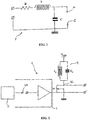
- la
figure 1 est un schéma illustrant un modèle électrique utilisé pour le résonateur modélisant une bobine-bougie de génération de plasma; - la
figure 2 est un schéma illustrant un dispositif de génération d'une haute tension intégrant un amplificateur, utilisé pour l'alimentation et la commande d'une bobine bougie; - la
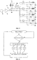
figure 3 illustre un premier mode de réalisation de répartition des fréquences de résonance des bobines-bougies selon l'invention, - la
figure 4 illustre un deuxième mode de réalisation de répartition des fréquences de résonance des bobines-bougies selon l'invention, - la
figure 5 illustre un schéma complet d'un allumage radiofréquence comprenant N bougies-bobines selon l'invention ; - la
figure 6 illustre un organigramme d'un exemple de mise en oeuvre de la commande de l'allumage selon l'invention.
- the
figure 1 is a diagram illustrating an electric model used for the resonator modeling a plasma generation coil-candle; - the
figure 2 is a diagram illustrating a device for generating a high voltage integrating an amplifier, used for powering and controlling a spark plug coil; - the
figure 3 illustrates a first embodiment of distribution of the resonant frequencies of the spark plugs according to the invention, - the
figure 4 illustrates a second embodiment of distribution of the resonant frequencies of the bobbins according to the invention, - the
figure 5 illustrates a complete diagram of a radiofrequency ignition comprising N candles-coils according to the invention; - the
figure 6 illustrates a flowchart of an example of implementation of the control of the ignition according to the invention.
La présente invention vise donc à commander une pluralité de circuits de génération de plasma de type bobines-bougies, en utilisant une unique voie d'amplification, autrement dit en utilisant un unique circuit d'alimentation du type amplificateur de puissance classe E comme décrit précédemment à la
Le principe sur lequel repose ce montage particulier consiste à exploiter, au niveau de la commande haute tension et haute fréquence générée par le circuit d'alimentation, la fréquence de résonance propre à chaque circuit de génération de plasma connecté en sortie du circuit d'alimentation.The principle on which this particular assembly is based consists in exploiting, at the level of the high voltage and high frequency control generated by the supply circuit, the resonance frequency specific to each plasma generation circuit connected at the output of the supply circuit. .
En effet, il apparaît qu'une répartition judicieuse des fréquences de résonance des circuits de génération de plasma permet de déterminer naturellement le transfert de puissance souhaitée du circuit d'alimentation vers l'un ou l'autre des circuits de génération de plasma. Ainsi, une même haute tension, appliquée simultanément en sortie du circuit d'alimentation aux bornes de la pluralité de circuits de génération de plasma qui y sont connectés, permet de commander sélectivement l'un parmi ces circuits de génération de plasma, selon que la fréquence de commande utilisée au niveau du circuit d'alimentation est calquée sensiblement sur la fréquence de résonance propre à celui-ci.Indeed, it appears that a judicious distribution of the resonant frequencies of the plasma generation circuits makes it possible naturally to determine the desired power transfer from the supply circuit to one or the other of the plasma generation circuits. Thus, the same high voltage, applied simultaneously at the output of the power supply circuit at the terminals of the plurality of plasma generation circuits connected to it, selectively controls one of these plasma generation circuits, depending on whether the control frequency used at the power supply circuit is modeled substantially on the resonance frequency specific thereto.
La condition pour permettre de commander de façon indépendante la pluralité de circuits de génération de plasma par l'intermédiaire d'un unique circuit d'alimentation est donc que chacun de ces circuits de génération de plasma présente une fréquence de résonance bien séparée des autres. Il s'agit en effet d'éviter les superpositions des domaines fréquentiels de résonance des résonateurs formant chaque circuit de génération de plasma et ainsi de s'affranchir des problèmes de multiples allumages simultanés.The condition for allowing independent control of the plurality of plasma generating circuits through a single power supply circuit is therefore that each of these plasma generating circuits has a resonant frequency well separated from the others. This is indeed to avoid overlapping resonance frequency resonator domains forming each plasma generation circuit and thus to overcome the problems of multiple simultaneous ignitions.
L'écart de fréquence de résonance entre les multiples circuits de génération de plasma connectés en parallèle en sortie du circuit d'alimentation unique doit être, de préférence, au minimum égal à un multiple de la bande passante de chaque résonateur. On pourra par exemple choisir de décaler la fréquence de résonance de chaque circuit de génération de plasma les uns par rapport aux autres d'une valeur égale à deux ou trois fois la bande passante de chaque circuit.The resonant frequency difference between the plural plasma generation circuits connected in parallel at the output of the single supply circuit must preferably be at least equal to a multiple of the bandwidth of each resonator. For example, it may be possible to shift the resonance frequency of each plasma generating circuit relative to each other by a value equal to two or three times the bandwidth of each circuit.
Plusieurs modes de réalisation sont envisageables pour réaliser un tel décalage de fréquence entre les fréquences de résonance de chaque circuit de génération de plasma.Several embodiments are possible to achieve such a frequency shift between the resonant frequencies of each plasma generation circuit.
Une première façon de faire est d'utiliser pour chaque circuit de génération de plasma une bobine-bougie, comme modélisée à la
Ce mode de réalisation où chaque circuit de génération de plasma est constitué d'un résonateur tel que représenté à la
En effet, il requiert l'adaptation du processus industriel à la production d'une pluralité de types bobines-bougies distincts et nécessite alors autant de références de bobines-bougies qu'il y a de voies à commander.Indeed, it requires the adaptation of the industrial process to the production of a plurality of different types of coils-candles and then requires as many references of coils-candles as there are channels to control.
Aussi, en référence aux
Comme illustré à la
Comme illustré à la
Les valeurs d'impédance des circuits 14 sont donc choisies pour que l'écart de fréquence de résonance entre chaque circuit de génération de plasma, constitué chacun par un couple impédance - résonateur, soit égal à au moins un multiple de la bande passante de chaque résonateur.The impedance values of the circuits 14 are thus chosen so that the difference in resonance frequency between each plasma generation circuit, each constituted by an impedance-resonator torque, is equal to at least one multiple of the bandwidth of each resonator.
On pourra par exemple utiliser pour les circuits d'impédance ajoutés, des inductances telles que la fréquence de résonance de chaque circuit de génération de plasma soit décalée de la valeur souhaitée.It will be possible, for example, to use, for the added impedance circuits, inductances such that the resonance frequency of each plasma generation circuit is shifted by the desired value.
Dans l'optique d'un rendement optimal du circuit d'alimentation ainsi que d'un fonctionnement optimal des bobines-bougies, on pourra utiliser des bobines-bougies identiques dont la fréquence de résonance est plus élevée que la fréquence de résonance à laquelle on souhaite commander les bobines-bougies. Dans ce cas, si les circuits d'impédance ajoutés sont des inductances, l'effet de cet ajout doit correspondre à baisser la valeur de la fréquence de résonance globale de chaque couple inductance/bobine-bougie.In the optics of an optimal performance of the supply circuit as well as an optimal operation of the coils-candles, it will be possible to use identical coils-candles whose resonant frequency is higher than the resonance frequency at which one wish to order the coils-candles. In this case, if the impedance circuits added are inductances, the effect of this addition must correspond to lowering the value of the overall resonant frequency of each inductance / coil-candle pair.
En variante, on pourra utiliser, pour l'une des voies à commander, une connexion simple sans ajout d'élément passif supplémentaire, tel qu'une inductance, en série avec la bobine-bougie.In a variant, it will be possible to use, for one of the channels to be controlled, a simple connection without adding additional passive element, such as an inductor, in series with the coil-candle.
Selon un autre mode de réalisation illustré à la
Le fait d'utiliser un câble impédant entre les bobines-bougies permet avantageusement de s'affranchir de l'utilisation de composants supplémentaires pour le décalage des bobines-bougies en fréquence, comme nécessité par le mode de réalisation de la
Les fréquences de résonance des différentes voies étant réparties de façon indépendante selon les principes exposés précédemment, le procédé de commande de l'unique circuit d'alimentation doit alors tenir compte de la fréquence adaptée à la voie à commander pour chaque allumage.The resonance frequencies of the different channels being distributed independently according to the principles described above, the control method of the single power supply circuit must then take into account the frequency adapted to the channel to be controlled for each ignition.
Pour ce faire, selon un mode de réalisation, le dispositif de commande 5 du circuit d'alimentation peut disposer d'une mémoire apte à conserver l'ordre de classement des fréquences correspondant à chacune des voies à commander.To do this, according to one embodiment, the control device 5 of the power supply circuit can have a memory capable of preserving the order of frequency classification corresponding to each of the channels to be controlled.
Ainsi, selon l'exemple de la
Le dispositif de commande comprend alors un module déterminant la fréquence du signal de commande à générer, parmi ces fréquences F1, F2, F3 et F4, en fonction du numéro de cylindre à allumer et de l'ordre de classement des fréquences préalablement mémorisé.The control device then comprises a module determining the frequency of the control signal to be generated, among these frequencies F1, F2, F3 and F4, as a function of the number of the cylinder to be switched on and the order of classification of the frequencies previously memorized.
Une fois la fréquence de commande déterminée, le dispositif de commande applique le signal de commande à ladite fréquence sur une interface de sortie, destiné à la commande de l'interrupteur M.Once the control frequency has been determined, the control device applies the control signal to said frequency on an output interface intended to control the switch M.
Le transfert de puissance sélectif vers le circuit de génération de plasma à commander pour l'allumage est alors naturellement géré par la fréquence de commande utilisée pour cet allumage.The selective power transfer to the plasma generating circuit to be controlled for ignition is then naturally managed by the control frequency used for this ignition.
Selon un mode de réalisation particulier, la détermination des fréquences de résonance à obtenir en sortie du circuit d'alimentation unique peut être maîtrisée par des méthodes de tabulation ou d'asservissement comme décrites dans les demandes de brevet français déposées au nom de la demanderesse
Par exemple, le dispositif de commande peut être doté d'une interface de réception de signaux de mesures de paramètres de fonctionnement du moteur (température d'huile moteur, couple moteur, régime moteur, angle d'allumage, température de l'air d'admission, pression dans la chambre de combustion, etc.) et/ou de signaux de mesures de paramètres de fonctionnement de l'alimentation, ainsi que d'un module mémoire particulier mémorisant des relations entre des signaux de mesures et la fréquence d'un signal de commande à générer. Le dispositif de commande détermine alors la fréquence d'un signal de commande à générer en fonction de signaux de mesures reçus sur l'interface de réception et des relations mémorisées dans le module de mémoire.For example, the control device may be provided with an interface for receiving engine operating parameter measurement signals (engine oil temperature, engine torque, engine speed, ignition angle, air temperature). inlet, pressure in the combustion chamber, etc.) and / or power supply operating parameter measurement signals, as well as a particular memory module storing relationships between measurement signals and the frequency of a control signal to be generated. The controller then determines the frequency of a control signal to be generated based on measurement signals received on the receiving interface and relationships stored in the memory module.
D'autres applications que la réalisation d'un allumage commandé de moteur à combustion peuvent être envisagées sans pour autant sortir du cadre de la présente invention, telles que la réalisation d'un allumage dans un filtre à particule, ou d'un allumage de décontamination dans un système de climatisation.Other applications than the achievement of a controlled ignition of combustion engine can be envisaged without departing from the scope of the present invention, such as the realization of ignition in a particle filter, or ignition of decontamination in an air conditioning system.
Claims (6)
- Radio frequency plasma generating device, characterized in that it comprises:- a power supply circuit (2), comprising a switch (M) controlled by a control signal (V1) for applying an intermediate voltage (Vinter) to an output of the power supply circuit at a frequency defined by the control signal,- at least two plasma generation circuits (BB1, BB2, BB3, BB4) connected in parallel to the output of the power supply circuit, each plasma generation circuit having its own resonance frequency and being capable of generating a plasma when a high voltage level is applied to the output of the power supply circuit at a frequency roughly equal to the resonance frequency of the plasma generation circuit,- a device (5) for controlling the power supply circuit, determining the frequency of the control signal from one of the resonance frequencies (F1, F2, F3, F4) of the plasma generation circuits, so as to selectively control each plasma generation circuit according to the control frequency used, characterized in that each plasma generation circuit comprises a resonator (1), each resonator having an identical resonance frequency, and in that at least one of the plasma generation circuits also comprises means of shifting the resonance frequency of its resonator.
- Device according to Claim 1, characterized in that the frequency-shifting means comprise an impedance matching circuit (14) positioned in series between the output of the power supply circuit and the resonator.
- Device according to Claim 2, characterized in that the impedance matching circuit comprises an inductance.
- Device according to Claim 3, characterized in that the impedance matching circuit comprises an impeding link cable providing the connection between the output of the power supply circuit and each resonator, the length (L1, L2, L3) of the portion of cable between the resonators defining the frequency shift between the resonators.
- Device according to any one of the preceding claims, characterized in that each plasma generation circuit is designed to produce an ignition in one of the following implementations: controlled ignition in a combustion engine cylinder, ignition in a particle filter, decontamination ignition in an air conditioning system.
- Method of controlling the power supply of a plasma generating device, comprising a power supply circuit (2) having a switch (M) controlled by a control signal (V1) for applying an intermediate voltage (Vinter) at a frequency defined by the control signal to an output of the power supply circuit, to which at least two plasma generation circuits are connected in parallel, each plasma generation circuit comprising a resonator (1), each resonator having an identical resonance frequency, at least one of the plasma generation circuits also comprising means of shifting the resonance frequency of its resonator, each plasma generation circuit being designed to be selectively controlled at its own resonance frequency,
said method comprising the steps of:- reception of a request to determine a control frequency;- determination of the plasma generation circuit to be controlled;- determination of a control frequency that is roughly equal to the resonance frequency of the plasma generation circuit to be controlled;- generation of the control signal at the determined control frequency.
Applications Claiming Priority (2)
| Application Number | Priority Date | Filing Date | Title |
|---|---|---|---|
| FR0701499A FR2913298B1 (en) | 2007-03-01 | 2007-03-01 | CONTROL OF A PLURALITY OF CANDLE COILS VIA A SINGLE POWER FLOOR |
| PCT/FR2008/050310 WO2008113955A1 (en) | 2007-03-01 | 2008-02-25 | Control of a plurality of plug coils via a single power stage |
Publications (2)
| Publication Number | Publication Date |
|---|---|
| EP2115296A1 EP2115296A1 (en) | 2009-11-11 |
| EP2115296B1 true EP2115296B1 (en) | 2017-09-06 |
Family
ID=38566150
Family Applications (1)
| Application Number | Title | Priority Date | Filing Date |
|---|---|---|---|
| EP08762151.2A Not-in-force EP2115296B1 (en) | 2007-03-01 | 2008-02-25 | Control of a plurality of plug coils via a single power stage |
Country Status (9)
| Country | Link |
|---|---|
| US (1) | US8547020B2 (en) |
| EP (1) | EP2115296B1 (en) |
| JP (1) | JP5036830B2 (en) |
| KR (1) | KR20090115947A (en) |
| CN (1) | CN101622442B (en) |
| BR (1) | BRPI0807707A2 (en) |
| FR (1) | FR2913298B1 (en) |
| RU (1) | RU2009136346A (en) |
| WO (1) | WO2008113955A1 (en) |
Families Citing this family (19)
| Publication number | Priority date | Publication date | Assignee | Title |
|---|---|---|---|---|
| FR2934942B1 (en) * | 2008-08-05 | 2010-09-10 | Renault Sas | CONTROL OF THE FREQUENCY OF EXCITATION OF A RADIOFREQUENCY CANDLE. |
| DE102010015344B4 (en) * | 2010-04-17 | 2013-07-25 | Borgwarner Beru Systems Gmbh | A method for igniting a fuel-air mixture of a combustion chamber, in particular in an internal combustion engine by generating a corona discharge |
| DE102011052096B4 (en) * | 2010-09-04 | 2019-11-28 | Borgwarner Ludwigsburg Gmbh | A method of exciting an RF resonant circuit having as component an igniter for igniting a fuel-air mixture in a combustion chamber |
| JP2012159033A (en) * | 2011-01-31 | 2012-08-23 | Imagineering Inc | Engine |
| WO2012161231A1 (en) * | 2011-05-24 | 2012-11-29 | イマジニアリング株式会社 | Electromagnetic wave emitting device |
| DE202012004602U1 (en) * | 2012-05-08 | 2013-08-12 | Rosenberger Hochfrequenztechnik Gmbh & Co. Kg | High-frequency plasma ignition |
| CN104426411B (en) * | 2013-08-28 | 2018-02-23 | 贵阳帕斯玛环保技术有限公司 | A kind of single resonance high-frequency and high-voltage power supply |
| JP2017500480A (en) | 2013-12-12 | 2017-01-05 | フェデラル−モーグル・イグニション・カンパニーFederal−Mogul Ignition Company | Control system for corona ignition power supply |
| US9525274B2 (en) | 2014-04-29 | 2016-12-20 | Federal-Mogul Ignition Company | Distribution of corona igniter power signal |
| US9531167B2 (en) | 2014-06-02 | 2016-12-27 | Nxp Usa, Inc. | Device and method for connecting an RF generator to a coaxial conductor |
| JP6190793B2 (en) * | 2014-11-13 | 2017-08-30 | 三菱電機株式会社 | Ignition device for internal combustion engine |
| US9518555B2 (en) * | 2014-12-04 | 2016-12-13 | Freescale Semiconductor, Inc. | Radiation devices |
| EP3242010A4 (en) * | 2014-12-29 | 2018-01-17 | Imagineering, Inc. | Ignition system, and internal combustion engine |
| JP6449736B2 (en) * | 2015-08-05 | 2019-01-09 | 三菱電機株式会社 | Internal combustion engine ignition device |
| AT518968B1 (en) | 2016-07-08 | 2019-05-15 | Ge Jenbacher Gmbh & Co Og | Control device for a plurality of actuators of an internal combustion engine |
| JP2018025190A (en) * | 2016-08-09 | 2018-02-15 | サンケン電気株式会社 | Ignition device |
| JPWO2018225169A1 (en) * | 2017-06-07 | 2020-04-09 | イマジニアリング株式会社 | Ignition device |
| NL2022938B1 (en) * | 2019-04-12 | 2020-10-20 | Vitalfluid B V | Plasma activated fluid processing system |
| WO2023128627A1 (en) * | 2021-12-31 | 2023-07-06 | 인투코어테크놀로지 주식회사 | Plasma process system for multi-station |
Citations (2)
| Publication number | Priority date | Publication date | Assignee | Title |
|---|---|---|---|---|
| US5655210A (en) * | 1994-08-25 | 1997-08-05 | Hughes Aircraft Company | Corona source for producing corona discharge and fluid waste treatment with corona discharge |
| US20060132360A1 (en) * | 2004-10-15 | 2006-06-22 | Caimi Frank M | Method and apparatus for adaptively controlling antenna parameters to enhance efficiency and maintain antenna size compactness |
Family Cites Families (12)
| Publication number | Priority date | Publication date | Assignee | Title |
|---|---|---|---|---|
| US4317068A (en) * | 1979-10-01 | 1982-02-23 | Combustion Electromagnetics, Inc. | Plasma jet ignition system |
| JPS5859376A (en) * | 1981-10-05 | 1983-04-08 | Nissan Motor Co Ltd | Plasma igniter |
| EP0228840B1 (en) * | 1986-01-07 | 1991-07-17 | LUCAS INDUSTRIES public limited company | Pulse generating circuit for an ignition system |
| US5587630A (en) * | 1993-10-28 | 1996-12-24 | Pratt & Whitney Canada Inc. | Continuous plasma ignition system |
| DE19953710B4 (en) * | 1999-11-08 | 2010-06-17 | Robert Bosch Gmbh | Method and device for measurement window positioning for ion current measurement |
| DE10331418A1 (en) * | 2003-07-10 | 2005-01-27 | Bayerische Motoren Werke Ag | Plasma jet spark plug |
| FR2859869B1 (en) * | 2003-09-12 | 2006-01-20 | Renault Sa | PLASMA GENERATION SYSTEM. |
| DE102005036968A1 (en) * | 2005-08-05 | 2007-02-15 | Siemens Ag | Plasma ignition system and method of operation |
| JP2007221252A (en) * | 2006-02-14 | 2007-08-30 | General Res Of Electronics Inc | Receiver input circuit |
| FR2913299B1 (en) * | 2007-03-01 | 2009-04-17 | Renault Sas | PILOTAGE OF A PLURALITY OF CANDLE COILS VIA A SINGLE POWER STAGE. |
| FR2913297B1 (en) * | 2007-03-01 | 2014-06-20 | Renault Sas | OPTIMIZING THE GENERATION OF A RADIO FREQUENCY IGNITION SPARK |
| US8104444B2 (en) * | 2007-10-31 | 2012-01-31 | Caterpillar Inc. | Pre-chamber igniter having RF-aided spark initiation |
-
2007
- 2007-03-01 FR FR0701499A patent/FR2913298B1/en not_active Expired - Fee Related
-
2008
- 2008-02-25 BR BRPI0807707-0A patent/BRPI0807707A2/en not_active IP Right Cessation
- 2008-02-25 WO PCT/FR2008/050310 patent/WO2008113955A1/en active Application Filing
- 2008-02-25 CN CN2008800066976A patent/CN101622442B/en not_active Expired - Fee Related
- 2008-02-25 RU RU2009136346/06A patent/RU2009136346A/en not_active Application Discontinuation
- 2008-02-25 EP EP08762151.2A patent/EP2115296B1/en not_active Not-in-force
- 2008-02-25 KR KR1020097018199A patent/KR20090115947A/en not_active Application Discontinuation
- 2008-02-25 US US12/529,417 patent/US8547020B2/en active Active
- 2008-02-25 JP JP2009551244A patent/JP5036830B2/en not_active Expired - Fee Related
Patent Citations (2)
| Publication number | Priority date | Publication date | Assignee | Title |
|---|---|---|---|---|
| US5655210A (en) * | 1994-08-25 | 1997-08-05 | Hughes Aircraft Company | Corona source for producing corona discharge and fluid waste treatment with corona discharge |
| US20060132360A1 (en) * | 2004-10-15 | 2006-06-22 | Caimi Frank M | Method and apparatus for adaptively controlling antenna parameters to enhance efficiency and maintain antenna size compactness |
Also Published As
| Publication number | Publication date |
|---|---|
| WO2008113955A1 (en) | 2008-09-25 |
| JP5036830B2 (en) | 2012-09-26 |
| RU2009136346A (en) | 2011-04-10 |
| EP2115296A1 (en) | 2009-11-11 |
| CN101622442A (en) | 2010-01-06 |
| FR2913298A1 (en) | 2008-09-05 |
| FR2913298B1 (en) | 2009-04-17 |
| KR20090115947A (en) | 2009-11-10 |
| US20100194279A1 (en) | 2010-08-05 |
| BRPI0807707A2 (en) | 2014-05-27 |
| US8547020B2 (en) | 2013-10-01 |
| JP2010520399A (en) | 2010-06-10 |
| CN101622442B (en) | 2011-12-28 |
Similar Documents
| Publication | Publication Date | Title |
|---|---|---|
| EP2115296B1 (en) | Control of a plurality of plug coils via a single power stage | |
| FR2913299A1 (en) | Plasma generating device for internal combustion engine of vehicle, has power supply circuit with control device for determining frequency of control signal among resonance frequencies to selectively control coils-sparkplugs | |
| EP2134959B1 (en) | Optimum control of the resonant frequency of a resonator in a radio frequency ignition system | |
| EP2126341B1 (en) | Optimised generation of a radio frequency ignition spark | |
| EP2153056B1 (en) | Measuring device in a radiofrequency ignition system for internal combustion engine | |
| EP2205858B1 (en) | Device for measuring the ionization current in a radiofrequency ignition system for an internal combustion engine | |
| EP1961279B1 (en) | Optimization of the excitation frequency of a resonator | |
| EP2250366B1 (en) | Optimisation of the excitation frequency of a radiofrequency plug | |
| EP2315932B1 (en) | Monitoring of the excitation frequency of a radiofrequency spark plug | |
| EP2156160A1 (en) | Diagnosis of the fouling condition of sparkplugs in a radiofrequency ignition system | |
| EP2321524B1 (en) | Device for measuring the ionization current in a radiofrequency ignition system for an internal combustion engine | |
| WO2003044874A2 (en) | Device for controlling an electronically-monitored ultrasonic piezoelectric actuator, and method for using same | |
| FR3047573A1 (en) | METHOD FOR VOLTAGE CONTROL OF MOUNTED EQUIPMENT IN A MOTOR VEHICLE | |
| FR2946190A1 (en) | METHOD FOR DETECTING THE TYPE OF SPARK GENERATED BY A RADIOFREQUENCY IGNITION CANDLE COIL AND CORRESPONDING DEVICE | |
| WO2012160317A1 (en) | Power supply for radiofrequency ignition with dual-stage amplifier | |
| EP1420156A2 (en) | Control circuit for fuel injectors of a vehicle | |
| FR2920633A1 (en) | METHOD FOR CONTROLLING THE AVERAGE POWER DISSIPPED BY A LAMP IN A MOTOR VEHICLE | |
| FR2476755A1 (en) | Ignition system for IC engine - has chopper connecting parallel prim. windings of ignition transformers to voltage supply | |
| EP0171523A2 (en) | Electronic apparatus liable to be fastened upon a motorcar working on gasoline or gas | |
| FR2920613A1 (en) | High voltage transistor i.e. metal oxide semiconductor transistor, control device i.e. driver, for vehicle, has transistor whose grid is connected to terminal by bipolar transistor arranged on base arrangement and controlled by current | |
| FR2969222A1 (en) | Method for controlling ignition of internal combustion engine of motor vehicle, involves monitoring occurrence of first controlling signal on ignition spark plug, and generating second signal at spark plug when first signal is absent |
Legal Events
| Date | Code | Title | Description |
|---|---|---|---|
| PUAI | Public reference made under article 153(3) epc to a published international application that has entered the european phase |
Free format text: ORIGINAL CODE: 0009012 |
|
| 17P | Request for examination filed |
Effective date: 20090730 |
|
| AK | Designated contracting states |
Kind code of ref document: A1 Designated state(s): AT BE BG CH CY CZ DE DK EE ES FI FR GB GR HR HU IE IS IT LI LT LU LV MC MT NL NO PL PT RO SE SI SK TR |
|
| DAX | Request for extension of the european patent (deleted) | ||
| 17Q | First examination report despatched |
Effective date: 20160613 |
|
| GRAP | Despatch of communication of intention to grant a patent |
Free format text: ORIGINAL CODE: EPIDOSNIGR1 |
|
| INTG | Intention to grant announced |
Effective date: 20170301 |
|
| GRAS | Grant fee paid |
Free format text: ORIGINAL CODE: EPIDOSNIGR3 |
|
| GRAA | (expected) grant |
Free format text: ORIGINAL CODE: 0009210 |
|
| AK | Designated contracting states |
Kind code of ref document: B1 Designated state(s): AT BE BG CH CY CZ DE DK EE ES FI FR GB GR HR HU IE IS IT LI LT LU LV MC MT NL NO PL PT RO SE SI SK TR |
|
| REG | Reference to a national code |
Ref country code: GB Ref legal event code: FG4D Free format text: NOT ENGLISH |
|
| REG | Reference to a national code |
Ref country code: CH Ref legal event code: EP Ref country code: AT Ref legal event code: REF Ref document number: 926189 Country of ref document: AT Kind code of ref document: T Effective date: 20170915 |
|
| REG | Reference to a national code |
Ref country code: IE Ref legal event code: FG4D Free format text: LANGUAGE OF EP DOCUMENT: FRENCH |
|
| REG | Reference to a national code |
Ref country code: DE Ref legal event code: R096 Ref document number: 602008052022 Country of ref document: DE |
|
| REG | Reference to a national code |
Ref country code: NL Ref legal event code: MP Effective date: 20170906 |
|
| REG | Reference to a national code |
Ref country code: LT Ref legal event code: MG4D |
|
| PG25 | Lapsed in a contracting state [announced via postgrant information from national office to epo] |
Ref country code: HR Free format text: LAPSE BECAUSE OF FAILURE TO SUBMIT A TRANSLATION OF THE DESCRIPTION OR TO PAY THE FEE WITHIN THE PRESCRIBED TIME-LIMIT Effective date: 20170906 Ref country code: LT Free format text: LAPSE BECAUSE OF FAILURE TO SUBMIT A TRANSLATION OF THE DESCRIPTION OR TO PAY THE FEE WITHIN THE PRESCRIBED TIME-LIMIT Effective date: 20170906 Ref country code: FI Free format text: LAPSE BECAUSE OF FAILURE TO SUBMIT A TRANSLATION OF THE DESCRIPTION OR TO PAY THE FEE WITHIN THE PRESCRIBED TIME-LIMIT Effective date: 20170906 Ref country code: NO Free format text: LAPSE BECAUSE OF FAILURE TO SUBMIT A TRANSLATION OF THE DESCRIPTION OR TO PAY THE FEE WITHIN THE PRESCRIBED TIME-LIMIT Effective date: 20171206 Ref country code: SE Free format text: LAPSE BECAUSE OF FAILURE TO SUBMIT A TRANSLATION OF THE DESCRIPTION OR TO PAY THE FEE WITHIN THE PRESCRIBED TIME-LIMIT Effective date: 20170906 |
|
| REG | Reference to a national code |
Ref country code: AT Ref legal event code: MK05 Ref document number: 926189 Country of ref document: AT Kind code of ref document: T Effective date: 20170906 |
|
| REG | Reference to a national code |
Ref country code: FR Ref legal event code: PLFP Year of fee payment: 11 |
|
| PG25 | Lapsed in a contracting state [announced via postgrant information from national office to epo] |
Ref country code: LV Free format text: LAPSE BECAUSE OF FAILURE TO SUBMIT A TRANSLATION OF THE DESCRIPTION OR TO PAY THE FEE WITHIN THE PRESCRIBED TIME-LIMIT Effective date: 20170906 Ref country code: ES Free format text: LAPSE BECAUSE OF FAILURE TO SUBMIT A TRANSLATION OF THE DESCRIPTION OR TO PAY THE FEE WITHIN THE PRESCRIBED TIME-LIMIT Effective date: 20170906 Ref country code: BG Free format text: LAPSE BECAUSE OF FAILURE TO SUBMIT A TRANSLATION OF THE DESCRIPTION OR TO PAY THE FEE WITHIN THE PRESCRIBED TIME-LIMIT Effective date: 20171206 Ref country code: GR Free format text: LAPSE BECAUSE OF FAILURE TO SUBMIT A TRANSLATION OF THE DESCRIPTION OR TO PAY THE FEE WITHIN THE PRESCRIBED TIME-LIMIT Effective date: 20171207 |
|
| PG25 | Lapsed in a contracting state [announced via postgrant information from national office to epo] |
Ref country code: NL Free format text: LAPSE BECAUSE OF FAILURE TO SUBMIT A TRANSLATION OF THE DESCRIPTION OR TO PAY THE FEE WITHIN THE PRESCRIBED TIME-LIMIT Effective date: 20170906 |
|
| PG25 | Lapsed in a contracting state [announced via postgrant information from national office to epo] |
Ref country code: RO Free format text: LAPSE BECAUSE OF FAILURE TO SUBMIT A TRANSLATION OF THE DESCRIPTION OR TO PAY THE FEE WITHIN THE PRESCRIBED TIME-LIMIT Effective date: 20170906 Ref country code: CZ Free format text: LAPSE BECAUSE OF FAILURE TO SUBMIT A TRANSLATION OF THE DESCRIPTION OR TO PAY THE FEE WITHIN THE PRESCRIBED TIME-LIMIT Effective date: 20170906 Ref country code: PL Free format text: LAPSE BECAUSE OF FAILURE TO SUBMIT A TRANSLATION OF THE DESCRIPTION OR TO PAY THE FEE WITHIN THE PRESCRIBED TIME-LIMIT Effective date: 20170906 |
|
| PG25 | Lapsed in a contracting state [announced via postgrant information from national office to epo] |
Ref country code: AT Free format text: LAPSE BECAUSE OF FAILURE TO SUBMIT A TRANSLATION OF THE DESCRIPTION OR TO PAY THE FEE WITHIN THE PRESCRIBED TIME-LIMIT Effective date: 20170906 Ref country code: IS Free format text: LAPSE BECAUSE OF FAILURE TO SUBMIT A TRANSLATION OF THE DESCRIPTION OR TO PAY THE FEE WITHIN THE PRESCRIBED TIME-LIMIT Effective date: 20180106 Ref country code: SK Free format text: LAPSE BECAUSE OF FAILURE TO SUBMIT A TRANSLATION OF THE DESCRIPTION OR TO PAY THE FEE WITHIN THE PRESCRIBED TIME-LIMIT Effective date: 20170906 Ref country code: EE Free format text: LAPSE BECAUSE OF FAILURE TO SUBMIT A TRANSLATION OF THE DESCRIPTION OR TO PAY THE FEE WITHIN THE PRESCRIBED TIME-LIMIT Effective date: 20170906 Ref country code: IT Free format text: LAPSE BECAUSE OF FAILURE TO SUBMIT A TRANSLATION OF THE DESCRIPTION OR TO PAY THE FEE WITHIN THE PRESCRIBED TIME-LIMIT Effective date: 20170906 |
|
| REG | Reference to a national code |
Ref country code: DE Ref legal event code: R097 Ref document number: 602008052022 Country of ref document: DE |
|
| PLBE | No opposition filed within time limit |
Free format text: ORIGINAL CODE: 0009261 |
|
| STAA | Information on the status of an ep patent application or granted ep patent |
Free format text: STATUS: NO OPPOSITION FILED WITHIN TIME LIMIT |
|
| PG25 | Lapsed in a contracting state [announced via postgrant information from national office to epo] |
Ref country code: DK Free format text: LAPSE BECAUSE OF FAILURE TO SUBMIT A TRANSLATION OF THE DESCRIPTION OR TO PAY THE FEE WITHIN THE PRESCRIBED TIME-LIMIT Effective date: 20170906 |
|
| 26N | No opposition filed |
Effective date: 20180607 |
|
| PG25 | Lapsed in a contracting state [announced via postgrant information from national office to epo] |
Ref country code: SI Free format text: LAPSE BECAUSE OF FAILURE TO SUBMIT A TRANSLATION OF THE DESCRIPTION OR TO PAY THE FEE WITHIN THE PRESCRIBED TIME-LIMIT Effective date: 20170906 |
|
| REG | Reference to a national code |
Ref country code: CH Ref legal event code: PL |
|
| PG25 | Lapsed in a contracting state [announced via postgrant information from national office to epo] |
Ref country code: MT Free format text: LAPSE BECAUSE OF FAILURE TO SUBMIT A TRANSLATION OF THE DESCRIPTION OR TO PAY THE FEE WITHIN THE PRESCRIBED TIME-LIMIT Effective date: 20170906 Ref country code: MC Free format text: LAPSE BECAUSE OF FAILURE TO SUBMIT A TRANSLATION OF THE DESCRIPTION OR TO PAY THE FEE WITHIN THE PRESCRIBED TIME-LIMIT Effective date: 20170906 |
|
| GBPC | Gb: european patent ceased through non-payment of renewal fee |
Effective date: 20180225 |
|
| REG | Reference to a national code |
Ref country code: IE Ref legal event code: MM4A |
|
| REG | Reference to a national code |
Ref country code: BE Ref legal event code: MM Effective date: 20180228 |
|
| PG25 | Lapsed in a contracting state [announced via postgrant information from national office to epo] |
Ref country code: LU Free format text: LAPSE BECAUSE OF NON-PAYMENT OF DUE FEES Effective date: 20180225 Ref country code: LI Free format text: LAPSE BECAUSE OF NON-PAYMENT OF DUE FEES Effective date: 20180228 Ref country code: CH Free format text: LAPSE BECAUSE OF NON-PAYMENT OF DUE FEES Effective date: 20180228 |
|
| PG25 | Lapsed in a contracting state [announced via postgrant information from national office to epo] |
Ref country code: IE Free format text: LAPSE BECAUSE OF NON-PAYMENT OF DUE FEES Effective date: 20180225 |
|
| PG25 | Lapsed in a contracting state [announced via postgrant information from national office to epo] |
Ref country code: BE Free format text: LAPSE BECAUSE OF NON-PAYMENT OF DUE FEES Effective date: 20180228 Ref country code: GB Free format text: LAPSE BECAUSE OF NON-PAYMENT OF DUE FEES Effective date: 20180225 |
|
| PG25 | Lapsed in a contracting state [announced via postgrant information from national office to epo] |
Ref country code: TR Free format text: LAPSE BECAUSE OF FAILURE TO SUBMIT A TRANSLATION OF THE DESCRIPTION OR TO PAY THE FEE WITHIN THE PRESCRIBED TIME-LIMIT Effective date: 20170906 |
|
| PG25 | Lapsed in a contracting state [announced via postgrant information from national office to epo] |
Ref country code: HU Free format text: LAPSE BECAUSE OF FAILURE TO SUBMIT A TRANSLATION OF THE DESCRIPTION OR TO PAY THE FEE WITHIN THE PRESCRIBED TIME-LIMIT; INVALID AB INITIO Effective date: 20080225 Ref country code: PT Free format text: LAPSE BECAUSE OF FAILURE TO SUBMIT A TRANSLATION OF THE DESCRIPTION OR TO PAY THE FEE WITHIN THE PRESCRIBED TIME-LIMIT Effective date: 20170906 |
|
| PG25 | Lapsed in a contracting state [announced via postgrant information from national office to epo] |
Ref country code: CY Free format text: LAPSE BECAUSE OF FAILURE TO SUBMIT A TRANSLATION OF THE DESCRIPTION OR TO PAY THE FEE WITHIN THE PRESCRIBED TIME-LIMIT Effective date: 20170906 |
|
| PGFP | Annual fee paid to national office [announced via postgrant information from national office to epo] |
Ref country code: DE Payment date: 20220217 Year of fee payment: 15 |
|
| PGFP | Annual fee paid to national office [announced via postgrant information from national office to epo] |
Ref country code: FR Payment date: 20220217 Year of fee payment: 15 |
|
| REG | Reference to a national code |
Ref country code: DE Ref legal event code: R119 Ref document number: 602008052022 Country of ref document: DE |
|
| PG25 | Lapsed in a contracting state [announced via postgrant information from national office to epo] |
Ref country code: FR Free format text: LAPSE BECAUSE OF NON-PAYMENT OF DUE FEES Effective date: 20230228 Ref country code: DE Free format text: LAPSE BECAUSE OF NON-PAYMENT OF DUE FEES Effective date: 20230901 |