EP2106818B1 - System for compensating for pressure drop in a breathing assistance system - Google Patents
System for compensating for pressure drop in a breathing assistance system Download PDFInfo
- Publication number
- EP2106818B1 EP2106818B1 EP08006240.9A EP08006240A EP2106818B1 EP 2106818 B1 EP2106818 B1 EP 2106818B1 EP 08006240 A EP08006240 A EP 08006240A EP 2106818 B1 EP2106818 B1 EP 2106818B1
- Authority
- EP
- European Patent Office
- Prior art keywords
- pressure drop
- breathing assistance
- calibration
- pressure
- assistance system
- Prior art date
- Legal status (The legal status is an assumption and is not a legal conclusion. Google has not performed a legal analysis and makes no representation as to the accuracy of the status listed.)
- Active
Links
- 230000029058 respiratory gaseous exchange Effects 0.000 title claims abstract description 74
- 238000012360 testing method Methods 0.000 claims abstract description 45
- 238000004364 calculation method Methods 0.000 claims abstract description 21
- 238000009423 ventilation Methods 0.000 claims description 54
- 239000007789 gas Substances 0.000 description 77
- 238000000034 method Methods 0.000 description 22
- 230000001276 controlling effect Effects 0.000 description 4
- 230000006870 function Effects 0.000 description 4
- 238000012886 linear function Methods 0.000 description 4
- IJGRMHOSHXDMSA-UHFFFAOYSA-N Atomic nitrogen Chemical compound N#N IJGRMHOSHXDMSA-UHFFFAOYSA-N 0.000 description 2
- 238000004891 communication Methods 0.000 description 2
- 230000000977 initiatory effect Effects 0.000 description 2
- 210000003437 trachea Anatomy 0.000 description 2
- 239000003570 air Substances 0.000 description 1
- 230000004075 alteration Effects 0.000 description 1
- 208000008784 apnea Diseases 0.000 description 1
- QVGXLLKOCUKJST-UHFFFAOYSA-N atomic oxygen Chemical compound [O] QVGXLLKOCUKJST-UHFFFAOYSA-N 0.000 description 1
- 238000009530 blood pressure measurement Methods 0.000 description 1
- 229940079593 drug Drugs 0.000 description 1
- 239000003814 drug Substances 0.000 description 1
- 230000000694 effects Effects 0.000 description 1
- 238000004519 manufacturing process Methods 0.000 description 1
- 238000005259 measurement Methods 0.000 description 1
- 238000012544 monitoring process Methods 0.000 description 1
- 229910052757 nitrogen Inorganic materials 0.000 description 1
- 239000001301 oxygen Substances 0.000 description 1
- 229910052760 oxygen Inorganic materials 0.000 description 1
- 230000001105 regulatory effect Effects 0.000 description 1
- 239000000126 substance Substances 0.000 description 1
- 238000006467 substitution reaction Methods 0.000 description 1
- 230000000007 visual effect Effects 0.000 description 1
- XLYOFNOQVPJJNP-UHFFFAOYSA-N water Substances O XLYOFNOQVPJJNP-UHFFFAOYSA-N 0.000 description 1
Images

Classifications
-
- A—HUMAN NECESSITIES
- A61—MEDICAL OR VETERINARY SCIENCE; HYGIENE
- A61M—DEVICES FOR INTRODUCING MEDIA INTO, OR ONTO, THE BODY; DEVICES FOR TRANSDUCING BODY MEDIA OR FOR TAKING MEDIA FROM THE BODY; DEVICES FOR PRODUCING OR ENDING SLEEP OR STUPOR
- A61M16/00—Devices for influencing the respiratory system of patients by gas treatment, e.g. mouth-to-mouth respiration; Tracheal tubes
- A61M16/0003—Accessories therefor, e.g. sensors, vibrators, negative pressure
- A61M16/0009—Accessories therefor, e.g. sensors, vibrators, negative pressure with sub-atmospheric pressure, e.g. during expiration
-
- A—HUMAN NECESSITIES
- A61—MEDICAL OR VETERINARY SCIENCE; HYGIENE
- A61M—DEVICES FOR INTRODUCING MEDIA INTO, OR ONTO, THE BODY; DEVICES FOR TRANSDUCING BODY MEDIA OR FOR TAKING MEDIA FROM THE BODY; DEVICES FOR PRODUCING OR ENDING SLEEP OR STUPOR
- A61M16/00—Devices for influencing the respiratory system of patients by gas treatment, e.g. mouth-to-mouth respiration; Tracheal tubes
- A61M16/0051—Devices for influencing the respiratory system of patients by gas treatment, e.g. mouth-to-mouth respiration; Tracheal tubes with alarm devices
-
- A—HUMAN NECESSITIES
- A61—MEDICAL OR VETERINARY SCIENCE; HYGIENE
- A61M—DEVICES FOR INTRODUCING MEDIA INTO, OR ONTO, THE BODY; DEVICES FOR TRANSDUCING BODY MEDIA OR FOR TAKING MEDIA FROM THE BODY; DEVICES FOR PRODUCING OR ENDING SLEEP OR STUPOR
- A61M16/00—Devices for influencing the respiratory system of patients by gas treatment, e.g. mouth-to-mouth respiration; Tracheal tubes
- A61M16/021—Devices for influencing the respiratory system of patients by gas treatment, e.g. mouth-to-mouth respiration; Tracheal tubes operated by electrical means
- A61M16/022—Control means therefor
- A61M16/024—Control means therefor including calculation means, e.g. using a processor
- A61M16/026—Control means therefor including calculation means, e.g. using a processor specially adapted for predicting, e.g. for determining an information representative of a flow limitation during a ventilation cycle by using a root square technique or a regression analysis
-
- A—HUMAN NECESSITIES
- A61—MEDICAL OR VETERINARY SCIENCE; HYGIENE
- A61M—DEVICES FOR INTRODUCING MEDIA INTO, OR ONTO, THE BODY; DEVICES FOR TRANSDUCING BODY MEDIA OR FOR TAKING MEDIA FROM THE BODY; DEVICES FOR PRODUCING OR ENDING SLEEP OR STUPOR
- A61M16/00—Devices for influencing the respiratory system of patients by gas treatment, e.g. mouth-to-mouth respiration; Tracheal tubes
- A61M16/0057—Pumps therefor
- A61M16/0063—Compressors
-
- A—HUMAN NECESSITIES
- A61—MEDICAL OR VETERINARY SCIENCE; HYGIENE
- A61M—DEVICES FOR INTRODUCING MEDIA INTO, OR ONTO, THE BODY; DEVICES FOR TRANSDUCING BODY MEDIA OR FOR TAKING MEDIA FROM THE BODY; DEVICES FOR PRODUCING OR ENDING SLEEP OR STUPOR
- A61M16/00—Devices for influencing the respiratory system of patients by gas treatment, e.g. mouth-to-mouth respiration; Tracheal tubes
- A61M16/04—Tracheal tubes
-
- A—HUMAN NECESSITIES
- A61—MEDICAL OR VETERINARY SCIENCE; HYGIENE
- A61M—DEVICES FOR INTRODUCING MEDIA INTO, OR ONTO, THE BODY; DEVICES FOR TRANSDUCING BODY MEDIA OR FOR TAKING MEDIA FROM THE BODY; DEVICES FOR PRODUCING OR ENDING SLEEP OR STUPOR
- A61M16/00—Devices for influencing the respiratory system of patients by gas treatment, e.g. mouth-to-mouth respiration; Tracheal tubes
- A61M16/06—Respiratory or anaesthetic masks
-
- A—HUMAN NECESSITIES
- A61—MEDICAL OR VETERINARY SCIENCE; HYGIENE
- A61M—DEVICES FOR INTRODUCING MEDIA INTO, OR ONTO, THE BODY; DEVICES FOR TRANSDUCING BODY MEDIA OR FOR TAKING MEDIA FROM THE BODY; DEVICES FOR PRODUCING OR ENDING SLEEP OR STUPOR
- A61M16/00—Devices for influencing the respiratory system of patients by gas treatment, e.g. mouth-to-mouth respiration; Tracheal tubes
- A61M16/0003—Accessories therefor, e.g. sensors, vibrators, negative pressure
- A61M2016/0015—Accessories therefor, e.g. sensors, vibrators, negative pressure inhalation detectors
- A61M2016/0018—Accessories therefor, e.g. sensors, vibrators, negative pressure inhalation detectors electrical
- A61M2016/0021—Accessories therefor, e.g. sensors, vibrators, negative pressure inhalation detectors electrical with a proportional output signal, e.g. from a thermistor
-
- A—HUMAN NECESSITIES
- A61—MEDICAL OR VETERINARY SCIENCE; HYGIENE
- A61M—DEVICES FOR INTRODUCING MEDIA INTO, OR ONTO, THE BODY; DEVICES FOR TRANSDUCING BODY MEDIA OR FOR TAKING MEDIA FROM THE BODY; DEVICES FOR PRODUCING OR ENDING SLEEP OR STUPOR
- A61M16/00—Devices for influencing the respiratory system of patients by gas treatment, e.g. mouth-to-mouth respiration; Tracheal tubes
- A61M16/0003—Accessories therefor, e.g. sensors, vibrators, negative pressure
- A61M2016/003—Accessories therefor, e.g. sensors, vibrators, negative pressure with a flowmeter
- A61M2016/0033—Accessories therefor, e.g. sensors, vibrators, negative pressure with a flowmeter electrical
- A61M2016/0042—Accessories therefor, e.g. sensors, vibrators, negative pressure with a flowmeter electrical in the expiratory circuit
-
- A—HUMAN NECESSITIES
- A61—MEDICAL OR VETERINARY SCIENCE; HYGIENE
- A61M—DEVICES FOR INTRODUCING MEDIA INTO, OR ONTO, THE BODY; DEVICES FOR TRANSDUCING BODY MEDIA OR FOR TAKING MEDIA FROM THE BODY; DEVICES FOR PRODUCING OR ENDING SLEEP OR STUPOR
- A61M16/00—Devices for influencing the respiratory system of patients by gas treatment, e.g. mouth-to-mouth respiration; Tracheal tubes
- A61M16/10—Preparation of respiratory gases or vapours
- A61M16/1005—Preparation of respiratory gases or vapours with O2 features or with parameter measurement
- A61M2016/102—Measuring a parameter of the content of the delivered gas
-
- A—HUMAN NECESSITIES
- A61—MEDICAL OR VETERINARY SCIENCE; HYGIENE
- A61M—DEVICES FOR INTRODUCING MEDIA INTO, OR ONTO, THE BODY; DEVICES FOR TRANSDUCING BODY MEDIA OR FOR TAKING MEDIA FROM THE BODY; DEVICES FOR PRODUCING OR ENDING SLEEP OR STUPOR
- A61M2205/00—General characteristics of the apparatus
- A61M2205/33—Controlling, regulating or measuring
- A61M2205/3368—Temperature
-
- A—HUMAN NECESSITIES
- A61—MEDICAL OR VETERINARY SCIENCE; HYGIENE
- A61M—DEVICES FOR INTRODUCING MEDIA INTO, OR ONTO, THE BODY; DEVICES FOR TRANSDUCING BODY MEDIA OR FOR TAKING MEDIA FROM THE BODY; DEVICES FOR PRODUCING OR ENDING SLEEP OR STUPOR
- A61M2205/00—General characteristics of the apparatus
- A61M2205/50—General characteristics of the apparatus with microprocessors or computers
- A61M2205/502—User interfaces, e.g. screens or keyboards
- A61M2205/505—Touch-screens; Virtual keyboard or keypads; Virtual buttons; Soft keys; Mouse touches
-
- A—HUMAN NECESSITIES
- A61—MEDICAL OR VETERINARY SCIENCE; HYGIENE
- A61M—DEVICES FOR INTRODUCING MEDIA INTO, OR ONTO, THE BODY; DEVICES FOR TRANSDUCING BODY MEDIA OR FOR TAKING MEDIA FROM THE BODY; DEVICES FOR PRODUCING OR ENDING SLEEP OR STUPOR
- A61M2205/00—General characteristics of the apparatus
- A61M2205/50—General characteristics of the apparatus with microprocessors or computers
- A61M2205/52—General characteristics of the apparatus with microprocessors or computers with memories providing a history of measured variating parameters of apparatus or patient
-
- A—HUMAN NECESSITIES
- A61—MEDICAL OR VETERINARY SCIENCE; HYGIENE
- A61M—DEVICES FOR INTRODUCING MEDIA INTO, OR ONTO, THE BODY; DEVICES FOR TRANSDUCING BODY MEDIA OR FOR TAKING MEDIA FROM THE BODY; DEVICES FOR PRODUCING OR ENDING SLEEP OR STUPOR
- A61M2205/00—General characteristics of the apparatus
- A61M2205/70—General characteristics of the apparatus with testing or calibration facilities
Abstract
Description
- The present disclosure is related to breathing assistance systems, e.g., systems and methods for compensating for pressure drop in a breathing assistance system.
- Breathing assistance systems such as ventilators and CPAP devices are used to provide various types of breathing assistance to patients. Typically, a patient is connected to a breathing assistance system by a connection system, which may include, for example, a patient circuit, a mask, nasal pillows, tracheal tube, and/or other conduits and connection devices. In some breathing assistance systems, the pressure delivered to the patient, or the pressure at the patient end of the connection system, is useful to the breathing assistance system, e.g., as feedback to the breathing assistance system or as an input for controlling the operation of the breathing assistance system.
- When delivering gas to a patient via a patient connection system, it is often difficult or unfeasible to measure the pressure near the patient end of the connection system. Thus, pressure may be measured near the gas delivery device of the breathing assistance system (e.g., the ventilator outlet or CPAP box). In some instances, the pressure sensor is located within the ventilator or CPAP box housing. However, as known in the field, the pressure measured near the gas delivery device (i.e., near the end of the connection system opposite the patient) may not provide the most accurate data regarding the pressure at the patient end of the connection system, based at least in part on pressure drop effects in the patient connection system.
- Document
US2004/0118403 discloses a CPAP apparatus that can be calibrated for different mask systems and hoses by including sensors configured to measure flow and pressure at a flow generator of the CPAP apparatus. When the flow generator is fitted to a new mask system, or any changes are made to an existing mask system, mask or patient interface and/or hose, a method for calibrating the flow generator for the new mask system, mask and/or hose is provided. The method includes determining air flow characteristics using flow measurements made during a first test period when the flow through the mask system is open, measuring or estimating pressure in the mask system during a second test period when the flow through the mask system is blocked and determining air flow characteristics of the diffuser of the mask system using the air flow characteristics of the air delivery hose determined during the first test period and the pressure measurements made during the second test period. - According to a main embodiment of the present invention, a breathing assistance system is provided as defined in the
independent claim 1. - There is also described a method for determining pressure drop in an apparatus of a breathing assistance system. One or more pressure drop calibration tests are performed, each pressure drop calibration test measuring a pressure drop in gas flowing through a breathing assistance system apparatus at a particular flow rate. A non-linear equation is generated based at least on the results of the one or more pressure drop calibration tests, the non-linear equation relating (a) pressure drop in gas flowing through the breathing assistance system apparatus with (b) flow rate of gas flowing through the breathing assistance system apparatus. Pressure drops in gas flowing through the breathing assistance system apparatus may then be determined for various flow rates based at least on the generated non-linear equation.
- There is further described another method for facilitating the determination of a pressure drop in an apparatus of a breathing assistance system. Multiple pressure drop calibration tests are preformed, each pressure drop calibration test measuring a pressure drop in gas flowing through a breathing assistance system apparatus at a particular flow rate. Coefficients for multiple linear line segments are calculated based on the results of the multiple pressure drop calibration tests, the multiple linear line segments collectively approximating a non-linear relationship between (a) pressure drop in gas flowing through the breathing assistance system apparatus and (b) flow rate of gas flowing through the breathing assistance system apparatus. The calculated coefficients for the multiple linear line segments are stored such that the calculated coefficients may be accessed while providing breathing assistance to a patient to determine pressure drops in gas flowing through the breathing assistance system apparatus for various flow rates.
- Also another method for determining pressure drop in an apparatus of a breathing assistance system is described. A look-up table of coefficients for linear equations representing multiple line segments is stored, the line segments collectively approximating a non-linear relationship between (a) pressure drop in gas flowing through the breathing assistance system apparatus and (b) flow rate of gas flowing through the breathing assistance system apparatus. A measured flow rate value for gas flowing through the breathing assistance system apparatus is received, and one or more coefficients corresponding to a particular line segment corresponding with the measured flow rate value is accessed from the stored look-up table. The one or more accessed coefficients corresponding to the particular line segment may then be used to calculate a pressure drop corresponding with the measured flow rate value.
- Some embodiments of the disclosure may be understood by referring, in part, to the following description and the accompanying drawings, in which like reference numbers refer to the same or like parts and wherein:
-
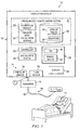
FIGURE 1 illustrates an examplebreathing assistance system 10 for communicating gas to and/or from a patient, and for calculating and compensating for pressure drop associated with such gas communication, according to one embodiment of the disclosure; -
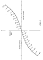
FIGURE 2 illustrates an example graph of pressure drop versus flow rate of gas flow through an apparatus, including calibration test results and corresponding line segments, according to an example embodiment; -
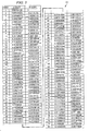
FIGURE 3 illustrates an example look-up table of coefficient pairs for line segment equations for use in calculating pressure drops for various flow rate values, according to an example embodiment of the disclosure; and -
FIGURE 4 is a graph illustrating example empirical results obtained from testing various configurations of connection system apparatuses, which illustrates the non-linear nature of the relationship between pressure drop and flow rate through such connection system apparatuses. - Selected embodiments of the disclosure may be understood by reference, in part, to
FIGURES 1-4 , wherein like numbers refer to same and like parts. The present disclosure relates generally to methods for compensating for pressure drop in a breathing assistance system. As known in the field, when delivering gas to a patient via a patient connection system (e.g., a patient circuit), the pressure measured near the outlet of the gas delivery system (e.g., ventilator or CPAP box) may not provide accurate data regarding the actual pressure delivered to the patient, based at least in part on pressure drop inherent in the patient circuit or other conduit. In particular, due to such inherent pressure drop, the pressure measured near the outlet of the gas delivery system is typically greater than the actual pressure delivered to the patient in the case of positive flow in the direction of the patient, and lower than the actual pressure delivered to the patient in the case of negative flow in the direction of the patient. However, it is often necessary or desirable to measure the pressure near the outlet of the gas delivery system instead of at the patient end of the patient connection system. Accordingly, the present disclosure provides systems and methods for accurately calculating, or estimating, the pressure drop in the patient connection system for different gas flow rates, such that the gas delivery system can properly compensate for the pressure drop. -
FIGURE 1 illustrates an examplebreathing assistance system 10 for communicating gas to and/or from a patient, and for calculating and compensating for pressure drop associated with such gas communication, according to one embodiment of the disclosure.Breathing assistance system 10 may be generally configured to provide breathing assistance (e.g., providing ventilation and/or treating an apnea or other breathing condition) to apatient 11.Breathing assistance system 10 may include aventilation system 12 and aconnection system 14 for connectingventilation system 12 topatient 11. -
Ventilation system 12 may comprise any device, apparatus, or system for delivering breathing gas to a patient, e.g., a ventilator, a respirator, a CPAP device, or a BiPAP device.Connection system 14 may be generally configured to deliver gas fromventilation system 12 topatient 11 and/or to communicate exhaust gas away frompatient 11. For example,connection system 14 may comprise any suitable type of breathing circuit (e.g., a single-limb or dual-limb circuit) and/or a patient connection apparatus. For instance,connection system 14 may include a 6-foot patient circuit. A patient connection apparatus may include any device or devices configured to connect the breathing circuit to one or more breathing passageways ofpatient 11. For example, the patient connection apparatus may include a patient connection tube directly connected to the patient's trachea, an artificial airway (e.g., an endotracheal tube or other device) inserted in the patient's trachea, and/or a mask, cushion or nasal pillows positioned over the patient's nose and/or mouth. -
Ventilation system 12 may include agas delivery system 20, acontroller 22, one ormore sensors 24,user interfaces 26, adisplay system 28, and a pressuredrop compensation system 30. -
Gas delivery system 20 may include any device or devices configured to generate, supply, and/or deliver gas (e.g., pressurized air) towardpatient 11 viaconnection system 14. For example,gas delivery system 20 may comprise a device capable of generating pressurized air (e.g., a motorized blower or piston-based device), a wall outlet through which pressurized air may be supplied (e.g., in a hospital or clinic), valves configured to control the supply of gas to the patient (e.g., a PSOL or other solenoid valve), one or more tanks of compressed gas, a compressor, or any other suitable source of pressurized or non-pressurized gas. In some embodiments,gas delivery system 20, in cooperation with other components of ventilation system 12 (e.g., an exhalation valve) may generate both positive and negative gas flows towardpatient 11. For example, a positive gas flow may be generated as gas is delivered topatient 11 during inhalation, while a negative gas flow may be generated as exhaust gas is communicated frompatient 11 during exhalation. - As used herein, the term "gas" may refer to any one or more gases and/or vaporized substances suitable to be delivered to and/or from a patient via one or more breathing orifices (e.g., the nose and/or mouth), such as air, nitrogen, oxygen, any other component of air, CO2, vaporized water, vaporized medicines, and/or any combination of two or more of the above, for example.
- As used herein, the term "patient" may refer to any person or animal that may receive breathing assistance from
system 10, regardless of the medical status, official patient status, physical location, or any other characteristic of the person. Thus, for example, patients may include persons under official medical care (e.g., hospital patients), persons not under official medical care, persons receiving care at a medical care facility, persons receiving home care, etc. -
Controller 22 may be operable to controlgas delivery system 20 to control the delivery of gas to and/or frompatient 11 based on various input received from a user (e.g., via a touch screen and/or other user interfaces provided by ventilation system 12), data received from pressuredrop compensation system 30, and/or data received from one ormore sensors 24. For example,controller 22 may regulate the pressure and/or flow rate of gas delivered to and/or from a patient based at least on pressure and/or flow data received fromsensors 24 and pressure drop data received from pressuredrop compensation system 30. -
Controller 22 may include, or have access to, one or more processors, memory devices, and any other suitable hardware or software. The one or more memory devices may store instructions (e.g., any suitable software, algorithms, or other logic or instructions that may be executed by one or more processors) for automatically controlling the operation of ventilation system 12 (e.g., controlling the pressure and/or flow rate output by gas delivery system 20) based on any of the various input data discussed herein. - Any one or
more sensors 24 may be provided for sensing, detecting, and/or monitoring one or more parameters related to the ventilation ofpatient 11, e.g., parameters regarding the ventilation provided byventilation system 12 and/or physiologicalparameters regarding patient 11. For example,sensors 24 may include one or more devices for measuring various parameters of gas flowing to or frompatient 11 orventilation system 12, e.g., the pressure, flow rate, flow volume, temperature, gas content, and/or humidity of such gas flow. - In certain embodiments,
sensors 24 may include apressure sensor 34 and aflow sensor 36 for measuring the pressure and flow, respectively, of gas delivered fromgas delivery system 20.Sensors system 10. For example, eachsensor 24 may be integrated with or coupled toventilation system 12, integrated with or coupled toconnection system 14, coupled topatient 11, or otherwise associated withsystem 10. - In certain embodiments,
pressure sensor 34 is located at or proximate a gas outlet of ventilation system 12 (e.g., at or proximate an outlet of gas delivery system 20). For example,pressure sensor 34 may be located inside or just outside a housing or enclosure ofventilation system 12. Thus,pressure sensor 34 may be positioned to measure the pressure of gas flow exitingventilation system 12 orgas delivery system 20, or the pressure of gas flow enteringconnection system 14, as generally indicated by arrow "P1" inFIGURE 1 . - In addition, in some embodiments,
flow sensor 36 may be located at or proximate a gas outlet of ventilation system 12 (e.g., at or proximate an outlet of gas delivery system 20). For example, flowsensor 36 may be located inside or just outside a housing or enclosure ofventilation system 12. Thus, flowsensor 36 may be positioned to measure the flow rate of gas flow exitingventilation system 12 orgas delivery system 20, or the flow rate of gas flow enteringconnection system 14. - In some embodiments or configurations, breathing
assistance system 10 may include ahumidifier 70, which may be integral with or separate from,ventilation system 12. The humidifier may be located and connected tosystem 10 in any suitable manner. Typically, thehumidifier 70 is located between the gas delivery system of theventilation system 12 and the patient. In some embodiments,humidifier 70 is located downstream ofpressure sensor 34, and may affect (e.g., increase) the pressure drop betweenpressure sensor 34 and the patient end ofconnection system 14.Humidifier 70 may include any known type of humidifier for use with a ventilator, CPAP system, or other type ofbreathing assistance system 10. -
User interfaces 26 may include any suitable device or devices allowing a user to interface withbreathing assistance system 10, e.g., to controlventilation system 12, to navigate through various display screens, to make selections, and/or to set, modify, or otherwise control variousparameters regarding system 10. For example,user interfaces 26 may allow a user to input desired performance parameters (e.g., pressure or flow rate) that may be communicated tocontroller 22 to control the operation ofgas delivery system 20 and/or other components ofsystem 10. -
User interfaces 26 may include a graphic user interface (GUI) 40, one or moremanual input devices 42 separate from the GUI, and/or any other input devices.GUI 40 may include a touch screen configured to display various information and provide an interface for accepting input from user (e.g., to navigate through various screens, to make selections, to set or modify various parameters, to change or configure the display, etc.).Manual input devices 42 may include any physical buttons, knobs, dials, switches, levers, or any other devices that may be manipulated by a user. -
Display device 28 may comprise a screen or any other device suitable for visually displaying medical data. For example,display device 28 may include a monitor, an LCD screen, LEDs, or any other visual device. In some embodiments,display device 28 anduser interfaces 26 may be at least partially integrated, e.g., whereventilation system 12 includes a touch screen orother GUI 40. - Pressure
drop compensation system 30 may be generally configured to calculate the pressure drop of gas flowing through an apparatus of system 10 (e.g.,connection system 14 or a portion thereof) such thatcontroller 22 may compensate for such pressure drop in controlling or regulatinggas delivery system 20. Pressuredrop compensation system 30 may include acalibration module 50, a pressuredrop calculation module 52, and one or more look-up tables 54 and/orequations 56 stored inmemory 58. -
Calibration module 50 is generally configured to calibrate anapparatus 60 ofsystem 10 for pressure drop calculations.Apparatus 60 may comprise any one or more components ofsystem 10 in which gas may experience a pressure drop. For example,apparatus 60 may compriseconnection system 14 or a portion thereof, e.g., a patient circuit or patient hose with or without an attached patient connection apparatus (e.g., as defined above), with or without an attachedhumidifier 70, or any combination of such components. -
Calibration module 50 may be configured to perform one or more calibration tests for a particular type or a particular instance of anapparatus 60 in order to generate look-up tables 54 and/orequations 56 stored inmemory 58. In some embodiments,calibration module 50 may calibrateapparatus 60 during a calibration mode performed before connectingpatient 11 toconnection system 14 and/or before providing breathing assistance topatient 11. In other embodiments, e.g., where calibration data is preloaded intomemory 58,calibration module 50 may not be included. - Look-up tables 54 and/or
equations 56 include data that may be used by pressuredrop calculation module 52 for calculating a pressure drop inapparatus 60 while providing breathing assistance topatient 11. In some embodiments, look-up tables 54 and/orequations 56 may be preloaded intomemory 58. In other embodiments, look-up tables 54 and/orequations 56 may be generated bycalibration module 50, as discussed above. -
Equations 56 may include: - one or more equations for calculating or estimating the pressure drop in gas flowing through apparatus 60 (e.g., due to resistance and variances associated with apparatus 60) as a function of the flow rate of gas flowing through
apparatus 60; and/or - one or more equations for calculating or estimating the "mask pressure," compensating for the pressure drop of the gas flow through
apparatus 60. As used herein, the term "mask pressure" refers to the pressure at the outlet or patient end ofapparatus 60, regardless of whether a mask is used in the particular configuration. - Examples of
such equations 56 include Equations (1) through (6b), discussed below. -
Equations 56 may be used to calculate or estimate pressure drop for positive and/or negative flow rates through apparatus 60 (e.g., in some configurations, a negative flow rate may be experienced during exhalation). In some embodiments, thesame equations 56 may be used for both positive and negative flow situations. In other embodiments,separate equations 56 may be used for positive and negative flow situations. For example, Equations (1) through (6b) provided below includeseparate equations 56 for positive and negative flow situations. - Look-up tables 54 may include, for example, coefficients for any of
equations 56. For example, as discussed below, in some embodiments, a look-up table 54 may include coefficients defining each of multiple (e.g., 80) different linear line segments that collectively approximate a non-linear function between pressure drop and flow rate. Such coefficients in look-up tables 54 may be easily accessed and used for calculating or estimating the pressure drop or mask pressure while providing breathing assistance to apatient 11. - In some embodiments, look-up tables 54 may include different tables corresponding to different types and/or configurations of
apparatuses 60. For example, look-up tables 54 may include a first table of equation coefficients for use with a 6' patient circuit and a second table of equation coefficients for use with an 8' patient circuit. As another example, look-up tables 54 may include a first table of equation coefficients for a configuration using a 6' patient circuit and including ahumidifier 70, and a second table of equation coefficients for a configuration using the same 6' patient circuit, but not including ahumidifier 70. - In addition, in embodiments in which the
same equations 56 may be used for both positive and negative flow situations, look-up tables 54 may include one set of equation coefficients for positive flow situations and another set of equation coefficients for negative flow situations. In embodiments in whichdifferent equations 56 may be used for positive and negative flow situations (e.g., Equations (1) through (6b) provided below), the same set of equation coefficient may be used for both positive and negative flow situations. - Pressure
drop calculation module 52 may be configured to use look-up tables 54 and/orequations 56 stored inmemory 58, along with any other suitable data (e.g., data from sensors 24) for calculating a pressure drop inapparatus 60, e.g., while providing breathing assistance topatient 11. For example, in some embodiments, pressuredrop calculation module 52 may use one ormore equations 56 and/or equation coefficients store in a look-up table 54 to calculate pressure drop inapparatus 60 based on measured flow rate values received fromflow sensor 36. -
Calibration module 50 and/or pressuredrop calculation module 52 may include, or have access to, one or more processors (e.g., a microprocessor, a microcontroller, DSP, ASIC, FPGA, or any other suitable processor), tangible memory devices (e.g., RAM, DRAM, ROM, EPROM, Flash memory, one or more hard disks, and/or any other memory or storage device), and any other suitable hardware, software, or firmware. The one or more memory devices may store instructions (e.g., any suitable software, algorithms, or other logic or instructions that may be executed by one or more processors) for providing any of the functionality of such modules discussed herein. -
Calibration module 50 is configured to calibrate a particular type, configuration, or instance ofapparatus 60 by performing multiple pressure drop calibration tests and determining equation coefficients for multiple straight line segments approximating a non-linear relationship between pressure drop throughapparatus 60 and flow rate throughapparatus 60. Each calibration test may include determining a pressure drop in gas flowing throughapparatus 60 at a particular flow rate. - Each calibration test may include delivering air through
apparatus 60 with the distal end of apparatus 60 (i.e., opposite the end connected to ventilation system 12) left open such that the pressure at the distal end is atmospheric pressure, as indicated inFIGURE 1 as P0. Using such technique, the pressure P1 measured adjacent the outlet ofventilation system 12 may be recorded as the pressure drop throughapparatus 60. -
Calibration module 50 may perform calibration tests at any number of different flow rates, which may include positive flow rates, negative flow rates, or both. For example,calibration module 50 may perform calibration tests at 10 or more different flow rates to obtain 10 or more corresponding pressure drop values. In certain embodiments,calibration module 50 may perform about 80 calibration tests at 80 different flow rates to obtain 80 corresponding pressure drop values. -
FIGURE 2 illustrates an example plot of the results of calibration tests of anapparatus 60 at six positive flow rates (providing pressure drop data points PD1 through PD6) and six negative flow rates (providing pressure drop data points PD1' through PD6'). - Although six positive and six negative data points are shown for illustrative purposes, any number (e.g., 80) of data points may be determined. In some embodiments, calibration tests may be performed and recorded using both positive and negative flow rates. In other embodiments, calibration tests may be performed and recorded using positive flow rates, and the results may simply be mirrored to provide the negative flow rate test results, which may reduce the total number of calibration tests by half.
- As shown in
FIGURE 2 , the pressure drop data points may indicate a non-linear relationship between pressure drop and flow rate. - After performing the various calibration tests at different flow rates to generate the pressure drop data points,
calibration module 50 may determine equation coefficients for straight line equations corresponding to the pressure drop data points. For example,calibration module 50 may determine coefficients Ai and Bi for each straight line L1 through L6 connecting adjacent pressure drop data points, according to the linear equation:
- where "ABS(Flow)" is the absolute value of the measured flow rate (e.g., by flow sensor 36).
- Thus,
calibration module 50 may determine six pairs of coefficients Ai and Bi, each coefficient pair corresponding to one of the six lines L1 through L6. These coefficient pairs may be stored in a look-up table 54 for use by pressuredrop calculation module 52 to calculate estimated mask pressure values based on flow rate values measured byflow sensor 36 while providing breathing assistance to apatient 11. As discussed below, these coefficient pairs may be used to calculate estimated mask pressure values for both positive flow and negative flow situations. - For example, for positive flow situations (e.g., during inhalation), pressure
drop calculation module 52 may calculate estimated mask pressure values using the equation:
or, substituting Equation (1) into Equation (2a):
- where "Measured P1" is the measured pressure at location P1, and
- "Flow" is the measured flow rate (e.g., by flow sensor 36).
- Similarly, for negative flow situations (e.g., during exhalation), pressure
drop calculation module 52 may calculate estimated mask pressure values using the equation:
or, substituting Equation (1) into Equation (2b):
- where "Measured P1" is the measured pressure at location P1, and "ABS(Flow)" is the absolute value of the measured flow rate (e.g., by flow sensor 36).
- As discussed above, multiple look-up tables 54 may be generated and/or maintained in
memory 58, corresponding to any number of different types, configurations, or instances ofapparatus 60. Pressuredrop calculation module 52 may access the appropriate look-up tables 54 based on input received from a user (e.g., via a user selection of a particular configuration or type of patient circuit) or automatically via other components ofventilation system 12 and/or connection system 14 (e.g.,ventilation system 12 may automatically identify the particular type of patient circuit connected toventilation system 12, or whether a humidifier is connected toventilation system 12, and send appropriate signals to pressuredrop calculation module 52. -
FIGURE 3 illustrates an example look-up table 54 including 80 coefficient pairs for 80 line segments, for an example in whichapparatus 60 comprises a 6 foot patient hose without a humidifier, according to an example embodiment of the disclosure. The coefficient pairs in look-up table 54 may be used for calculating pressure drops in both positive flow and negative flow situations. For example, the same coefficient pair may be used for a measured flow rate of 1.5 1/s and a measured flow rate of -1.5 1/s. - In some embodiments,
calibration module 50 inventilation system 12 may perform the calibration process discussed above for aparticular apparatus 60 connected toventilation system 12, and store the results in one or more look-up tables 54. Thus,ventilation system 12 may be used to calibrate a particular type, configuration, and/or instance ofapparatus 60 to be used for providing breathing assistance to apatient 11. Such calibration may be performed at any suitable time prior to providing breathing assistance to apatient 11, e.g., just prior to initiating breathing assistance topatient 11, upon the initial configuration ofventilation system 12, or upon receiving a new type of apparatus 60 (e.g., a new brand or model of patient circuit). - In some embodiments, the calibration process discussed above may be performed on another ventilation system or during manufacturing of
ventilation system 12, and look-up tables 54 may be pre-loaded intomemory 58 inventilation system 12. In still other embodiments, one or more look-up tables 54 may be pre-loaded intomemory 58, butcalibration module 50 may subsequently be used to generate and store additional look-up tables 54 (e.g., for new types or configurations of apparatus 60). - In alternative embodiments,
calibration module 50 may calculate or determine a non-linear function between pressure drop throughapparatus 60 and flow rate throughapparatus 60. For example,calibration module 50 may generate one or more non-linear equation(s) that approximates the relationship between pressure drop and flow rate using some or all of the calibration test data points. Such non-linear equation(s) may include equations of any order (e.g., second order, third order, fourth order, etc.), which order may be selected by a user or selected automatically bycalibration module 50.Calibration module 50 may generate such non-linear equation(s) using any known curve-fitting techniques or other suitable techniques. -
Calibration module 50 is further configured to automatically calibrate a particular type, configuration, or instance ofapparatus 60 by generating a non-linear function between pressure drop throughapparatus 60 and flow rate throughapparatus 60, and determining equation coefficients for multiple straight line segments approximating the generated non-linear function. The pressure drop in gas flowing through apparatus 60 (e.g., due to resistance and variances associated with apparatus 60) as a function of the flow rate of gas flowing throughapparatus 60. may be written as:
where: - -- "Pressure Drop" is the pressure drop in gas flowing through
apparatus 60, and - -- "Flow" is the flow rate of gas flowing through
apparatus 60. -
FIGURE 4 is agraph 120 illustrating example empirical results obtained from testing two configurations ofapparatus 60 -- a 6' patient circuit without a humidifier and the 6' patient circuit with an attached humidifier -- which illustrates the non-linear nature of the relationship between pressure drop and flow rate. Althoughgraph 120 only shows results for positive flow rates, similar results (but mirrored across the x- and y-axes) may be obtained for negative flow rates. - As shown in
FIGURE 4 , based on these and other empirical results, it has been observed that the pressure drop as a function of flow rate can be estimated as a second degree polynomial equation, which may be written as follows:
where: - -- "Pressure Drop" is the pressure drop in gas flowing through
apparatus 60, - -- "ABS(Flow)" is the absolute value of the flow rate through
apparatus 60, and - -- "X" and "Y" are coefficients.
-
Calibration module 50 may solve for coefficients X and Y in Equation (5) by performing one or more pressure drop calibration tests at one or more positive and/or negative flow rates. Such calibration tests may be performed as discussed above, e.g., by delivering air throughapparatus 60 with the distal end of apparatus 60 (i.e., opposite the end connected to ventilation system 12) left open such that the pressure at the distal end is atmospheric pressure, as indicated inFIGURE 1 as P0. - Equation (5), including coefficients X and Y solved based on the calibration test(s), may be stored in
memory 58. With coefficients X and Y being solved, Equation (5) may be used either directly or indirectly for calculating mask pressure values based on positive and/or negative flow rate values measured byflow sensor 36 while providing breathing assistance to apatient 11, as discussed below. - Direct use of Equation (5). In some embodiments, pressure
drop calculation module 52 may use Equation (5) (including solved coefficients X and Y) directly for calculating estimated mask pressure values.Flow sensor 36 may measure and communicate flow rate values while providing breathing assistance to apatient 11. Pressuredrop calculation module 52 may plug the flow rate values directly into Equation (5) to calculate estimated pressure drop values. - Further, for positive flow situations (e.g., during inhalation), Equation (5) may be substituted into Equation (3a) to obtain Equation (6a):

- "Measured P1" is the measured pressure at location P1, and
- "Flow" is the measured flow rate (e.g., by flow sensor 36),
- Thus, pressure
drop calculation module 52 may plug received flow rate values directly into Equation (6a) to directly calculate estimated mask pressure values in positive flow situations. - Similarly, for negative flow situations (e.g., during exhalation), Equation (5) may be substituted into Equation (3b) to obtain Equation (6b):

- where "Measured P1" is the measured pressure at location P1,
- "Flow" is the measured flow rate (e.g., by flow sensor 36), and
- "ABS(Flow)" is the absolute value of "Flow"
- Thus, pressure
drop calculation module 52 may plug received flow rate values directly into Equation (6b) to directly calculate estimated mask pressure values in negative flow situations. - Indirect use of Equation (5). In some embodiments, Equation (5) (including solved coefficients X and Y) may be used indirectly for calculating estimated mask pressure values. In such embodiments,
calibration module 50 may approximate the non-linear relationship between pressure drop and flow rate defined by Equation (5) using a number (e.g., 80) straight line segments.Calibration module 50 may calculate coefficients for equations representing each of such straight line segments, and store such coefficients in a look-up table 54. - For example,
calibration module 50 may calculate coefficient pairs Ai and Bi for Equations (3a) and (3b) corresponding to each line segment.

-
Calibration module 50 may use any known or suitable techniques for calculating the coefficient pairs Ai and Bi for the line segments approximating the non-linear curve defined by Equation (5). For example,calibration module 50 may determine the slope of the curve defined by Equation (5) at each of a number (e.g., 80) of flow rate values, record the corresponding slopes as Ai for each respective flow rate value (or for the data intervals corresponding to each respective flow rate value), and calculate the corresponding Bi values. As another example,calibration module 50 may calculate the pressure drop values for each of a number (e.g., 80) of flow rate values according to Equation (5), and use each adjacent pair of calculated pressure drop values as end-points for the multiple (e.g., 80) line segments collectively approximating the curve of Equation (5). - Regardless of the technique used for calculating the coefficient pairs Ai and Bi for the multiple line segments approximating the non-linear curve of Equation (5), such calculated coefficient pairs Ai and Bi may be stored in a look-up table 54. Later, while providing breathing assistance to
patient 11, pressuredrop calculation module 52 may access such look-up table 54 to calculate estimated mask pressure values based on flow rate values measured byflow sensor 36 using Equation (3a) (for positive flow rates) or Equation (3b) (for negative flow rates). -
Ventilation system 12 may initiate any of the calibration processes discusses above in various manners. In some embodiments,ventilation system 12 may allow the user to initiate a calibration of anapparatus 60 connected toventilation system 12. For example,ventilation system 12 may include one or more user interfaces 26 (e.g.,GUI 40 or one or more manual input devices 42) allowing the user to (a) initiate an automatic calibration ofapparatus 60, (b) initiate a line segment calibration ofapparatus 60, (c) instruct theventilation system 12 to access stored look-up tables 54 and/orequations 56 for aparticular apparatus 60, and/or (d) enter data identifying apparatus 60 (e.g., the type of patient circuit and/or whether a humidifier is attached). For example,ventilation system 12 may include an "auto calibration" button and a "line segment calibration" button for initiating such calibration processes. As another example, auser interface 26 may allow the user to select various parameters for a calibration process, e.g., a number of calibration tests to be performed, a range of flow rates for the calibration tests, a number of line segments to be calculated, and/or an order of a non-linear equation (e.g., third order equation) to be calculated (e.g., by curve fitting) to approximate the calibration test data. In some embodiments,GUI 40 may include any suitable buttons and/or menus for selecting and/or inputting any of the parameters discussed above. - In some embodiments,
ventilation system 12 may be configured to automatically access the appropriate look-up tables 54 and/orequations 56 based on data entered by the user identifying apparatus 60 (e.g., a serial number, part number, or type of patient circuit and/or whether a humidifier is attached). In other embodiments,ventilation system 12 may be configured to automatically obtain identificationinformation regarding apparatus 60, and access the corresponding look-up tables 54 and/orequations 56. For example,ventilation system 12 may be configured to automatically read data stored in non-volatile memory embedded in a patient circuit when the patient circuit is connected toventilation system 12. In such embodiments,ventilation system 12 may calibrate anapparatus 60, or access the appropriate look-up tables 54 and/orequations 56, automatically without user input. - It will be appreciated that while the disclosure is particularly described in the context of measuring and/or compensating for pressure drop in a conduit of a breathing assistance system, the apparatuses, techniques, and methods disclosed herein may be similarly applied in other contexts, e.g., measuring and/or compensating for pressure drops in gas flow in other medical devices. Additionally, it should be understood that various changes, substitutions and alterations can be made herein without departing from the scope of the disclosure as illustrated by the following claims.
Claims (10)
- A breathing assistance system configured to determine pressure drop, comprising:- a ventilation system (12); and- a patient connection apparatus (60) configured to deliver gas from the ventilation system (12) toward a patient (11);wherein the ventilation system (12) comprises:- a gas delivery system (20) configured to deliver gas toward a patient (11);- at least one pressure sensor (34) and at least one flow sensor (36) for measuring pressure and flow gas delivered by the gas delivery system (20); and- a pressure drop compensation system (30) operatively coupled with said pressure and flow sensors (34,36), comprising a calibration module (50) and a pressure drop calculation module (52) and configured to:perform one or more pressure drop calibration tests during which a distal end of said patient connection apparatus (60) is left open, each pressure drop calibration test measuring a pressure drop in gas flowing through said patient connection apparatus (60) at a particular flow rate;wherein the pressure drop compensation system (30) is configured to operate in an automatic calibration mode in which based at least on the results of the one or more pressure drop calibration tests, the calibration module (50) operates to determine and store coefficients of a non-linear equation approximating the relationship between pressure drop and flow rate of gas flowing through the breathing assistance system;wherein the pressure drop calculation module (52) is configured to determine pressure drops in gas flowing through the breathing assistance system for various flow rates based on the non-linear equation,characterised in thatthe pressure drop compensation system (30) is further configured to operate in a line segments calibration mode in which based at least on the results of the one or more pressure drop calibration tests, the calibration module (50) operates to determine and store in a look-up table coefficients for multiple linear line segments, wherein each line segment is determined by one of said pressure drop calibration test in which a flow rate and associated pressure is determined by said sensors (34,36), the multiple linear line segments collectively approximating the non-linear relationship between pressure drop and flow rate of gas flowing through the breathing assistance system, wherein the calculated coefficients may be accessed to determine pressure drops in gas flowing through the breathing assistance system apparatus for various flow rates, andthe ventilation system (12) further comprises a user interface (26) to select either said automatic calibration mode or said line segments calibration mode.
- A breathing assistance system according to Claim 1, wherein the non-linear equation is defined as:

wherein F designates the flow rate and X and Y coefficients determined by said pressure drop calibration tests. - A breathing assistance system according to Claim 1 or 2, wherein the line segment coefficients define a slope of a curve.
- A breathing assistance system according to Claim 1 or 2, wherein a line segment is determined by end points and wherein the end points are determined by said pressure drop calibration tests.
- A breathing assistance system according to one of the preceding claims, wherein each straight line segment is defined bv the following linear equation:

wherein i designates the straight line segment number, F is the flow rate and A and B are coefficients determined by said pressure drop equation. - A breathing assistance system according to one of the preceding claims, wherein about 80 pressure drop calibration tests are performed.
- A breathing assistance system according to one of the preceding claims, wherein the pressure drop calculation module (52) determines an estimated mask pressure by compensating a measured pressure at a current flow rate with a pressure drop at said measured flow rate determined by said automatic calibration mode or said line segments calibration module.
- A breathing assistance system according to one of the preceding claims, wherein the user interface (26) allows the user to instruct the ventilation system (12) to access stored look-up tables and/or stored equations for a particular apparatus (60).
- A breathing assistance system according to Claim 8, wherein said user interface is further configured to allow a user to select parameters of a selected calibration.
- A breathing assistance system according to Claim 9, wherein said parameters are selected from at least one of: number of calibration tests, range of flow rates, number of line segments, and order of a non-linear equation.
Priority Applications (2)
| Application Number | Priority Date | Filing Date | Title |
|---|---|---|---|
| EP08006240.9A EP2106818B1 (en) | 2008-03-31 | 2008-03-31 | System for compensating for pressure drop in a breathing assistance system |
| US12/410,310 US8353291B2 (en) | 2008-03-31 | 2009-03-24 | Systems and methods for compensating for pressure drop in a breathing assistance system |
Applications Claiming Priority (1)
| Application Number | Priority Date | Filing Date | Title |
|---|---|---|---|
| EP08006240.9A EP2106818B1 (en) | 2008-03-31 | 2008-03-31 | System for compensating for pressure drop in a breathing assistance system |
Publications (2)
| Publication Number | Publication Date |
|---|---|
| EP2106818A1 EP2106818A1 (en) | 2009-10-07 |
| EP2106818B1 true EP2106818B1 (en) | 2013-12-25 |
Family
ID=39618909
Family Applications (1)
| Application Number | Title | Priority Date | Filing Date |
|---|---|---|---|
| EP08006240.9A Active EP2106818B1 (en) | 2008-03-31 | 2008-03-31 | System for compensating for pressure drop in a breathing assistance system |
Country Status (2)
| Country | Link |
|---|---|
| US (1) | US8353291B2 (en) |
| EP (1) | EP2106818B1 (en) |
Families Citing this family (109)
| Publication number | Priority date | Publication date | Assignee | Title |
|---|---|---|---|---|
| US6024089A (en) | 1997-03-14 | 2000-02-15 | Nelcor Puritan Bennett Incorporated | System and method for setting and displaying ventilator alarms |
| FR2858236B1 (en) | 2003-07-29 | 2006-04-28 | Airox | DEVICE AND METHOD FOR SUPPLYING RESPIRATORY GAS IN PRESSURE OR VOLUME |
| US8021310B2 (en) | 2006-04-21 | 2011-09-20 | Nellcor Puritan Bennett Llc | Work of breathing display for a ventilation system |
| US7784461B2 (en) | 2006-09-26 | 2010-08-31 | Nellcor Puritan Bennett Llc | Three-dimensional waveform display for a breathing assistance system |
| US8267085B2 (en) | 2009-03-20 | 2012-09-18 | Nellcor Puritan Bennett Llc | Leak-compensated proportional assist ventilation |
| US10207069B2 (en) | 2008-03-31 | 2019-02-19 | Covidien Lp | System and method for determining ventilator leakage during stable periods within a breath |
| US8272379B2 (en) | 2008-03-31 | 2012-09-25 | Nellcor Puritan Bennett, Llc | Leak-compensated flow triggering and cycling in medical ventilators |
| US8792949B2 (en) | 2008-03-31 | 2014-07-29 | Covidien Lp | Reducing nuisance alarms |
| US8746248B2 (en) | 2008-03-31 | 2014-06-10 | Covidien Lp | Determination of patient circuit disconnect in leak-compensated ventilatory support |
| EP2320791B1 (en) | 2008-06-06 | 2016-08-31 | Covidien LP | Systems for ventilation in proportion to patient effort |
| US8528554B2 (en) | 2008-09-04 | 2013-09-10 | Covidien Lp | Inverse sawtooth pressure wave train purging in medical ventilators |
| US8551006B2 (en) | 2008-09-17 | 2013-10-08 | Covidien Lp | Method for determining hemodynamic effects |
| US8424520B2 (en) | 2008-09-23 | 2013-04-23 | Covidien Lp | Safe standby mode for ventilator |
| WO2010036816A1 (en) | 2008-09-25 | 2010-04-01 | Nellcor Puritan Bennett Llc | Inversion-based feed-forward compensation of inspiratory trigger dynamics in medical ventilators |
| US8181648B2 (en) | 2008-09-26 | 2012-05-22 | Nellcor Puritan Bennett Llc | Systems and methods for managing pressure in a breathing assistance system |
| US8393323B2 (en) | 2008-09-30 | 2013-03-12 | Covidien Lp | Supplemental gas safety system for a breathing assistance system |
| US8302602B2 (en) | 2008-09-30 | 2012-11-06 | Nellcor Puritan Bennett Llc | Breathing assistance system with multiple pressure sensors |
| US8113062B2 (en) | 2008-09-30 | 2012-02-14 | Nellcor Puritan Bennett Llc | Tilt sensor for use with proximal flow sensing device |
| US8424521B2 (en) | 2009-02-27 | 2013-04-23 | Covidien Lp | Leak-compensated respiratory mechanics estimation in medical ventilators |
| US8418691B2 (en) | 2009-03-20 | 2013-04-16 | Covidien Lp | Leak-compensated pressure regulated volume control ventilation |
| US8776790B2 (en) | 2009-07-16 | 2014-07-15 | Covidien Lp | Wireless, gas flow-powered sensor system for a breathing assistance system |
| US8789529B2 (en) | 2009-08-20 | 2014-07-29 | Covidien Lp | Method for ventilation |
| US8469030B2 (en) | 2009-12-01 | 2013-06-25 | Covidien Lp | Exhalation valve assembly with selectable contagious/non-contagious latch |
| US9289571B2 (en) | 2009-12-01 | 2016-03-22 | Fisher & Paykel Healthcare Limited | Breathing assistance apparatus |
| US8439037B2 (en) | 2009-12-01 | 2013-05-14 | Covidien Lp | Exhalation valve assembly with integrated filter and flow sensor |
| US8469031B2 (en) | 2009-12-01 | 2013-06-25 | Covidien Lp | Exhalation valve assembly with integrated filter |
| US8439036B2 (en) | 2009-12-01 | 2013-05-14 | Covidien Lp | Exhalation valve assembly with integral flow sensor |
| US8547062B2 (en) | 2009-12-02 | 2013-10-01 | Covidien Lp | Apparatus and system for a battery pack assembly used during mechanical ventilation |
| US8434481B2 (en) | 2009-12-03 | 2013-05-07 | Covidien Lp | Ventilator respiratory gas accumulator with dip tube |
| US9119925B2 (en) | 2009-12-04 | 2015-09-01 | Covidien Lp | Quick initiation of respiratory support via a ventilator user interface |
| US8418692B2 (en) | 2009-12-04 | 2013-04-16 | Covidien Lp | Ventilation system with removable primary display |
| USD649157S1 (en) | 2009-12-04 | 2011-11-22 | Nellcor Puritan Bennett Llc | Ventilator display screen with a user interface |
| USD638852S1 (en) | 2009-12-04 | 2011-05-31 | Nellcor Puritan Bennett Llc | Ventilator display screen with an alarm icon |
| US8924878B2 (en) | 2009-12-04 | 2014-12-30 | Covidien Lp | Display and access to settings on a ventilator graphical user interface |
| US8335992B2 (en) | 2009-12-04 | 2012-12-18 | Nellcor Puritan Bennett Llc | Visual indication of settings changes on a ventilator graphical user interface |
| US8482415B2 (en) | 2009-12-04 | 2013-07-09 | Covidien Lp | Interactive multilevel alarm |
| US20110152697A1 (en) * | 2009-12-18 | 2011-06-23 | K&Y Corporation | Circulatory Pressure Monitoring Using Infusion Pump Systems |
| US8499252B2 (en) | 2009-12-18 | 2013-07-30 | Covidien Lp | Display of respiratory data graphs on a ventilator graphical user interface |
| WO2011075706A1 (en) | 2009-12-18 | 2011-06-23 | K&Y Corporation | Infusion pump |
| US9262588B2 (en) | 2009-12-18 | 2016-02-16 | Covidien Lp | Display of respiratory data graphs on a ventilator graphical user interface |
| US20110146683A1 (en) * | 2009-12-21 | 2011-06-23 | Nellcor Puritan Bennett Llc | Sensor Model |
| AU2010334488B2 (en) * | 2009-12-21 | 2014-07-10 | Koninklijke Philips Electronics N.V. | Automatic identification of a patient interface device in a pressure support system |
| US8400290B2 (en) | 2010-01-19 | 2013-03-19 | Covidien Lp | Nuisance alarm reduction method for therapeutic parameters |
| US8707952B2 (en) | 2010-02-10 | 2014-04-29 | Covidien Lp | Leak determination in a breathing assistance system |
| US9302061B2 (en) | 2010-02-26 | 2016-04-05 | Covidien Lp | Event-based delay detection and control of networked systems in medical ventilation |
| US8539949B2 (en) | 2010-04-27 | 2013-09-24 | Covidien Lp | Ventilation system with a two-point perspective view |
| US8453643B2 (en) | 2010-04-27 | 2013-06-04 | Covidien Lp | Ventilation system with system status display for configuration and program information |
| US8511306B2 (en) | 2010-04-27 | 2013-08-20 | Covidien Lp | Ventilation system with system status display for maintenance and service information |
| US8638200B2 (en) | 2010-05-07 | 2014-01-28 | Covidien Lp | Ventilator-initiated prompt regarding Auto-PEEP detection during volume ventilation of non-triggering patient |
| US8607791B2 (en) | 2010-06-30 | 2013-12-17 | Covidien Lp | Ventilator-initiated prompt regarding auto-PEEP detection during pressure ventilation |
| US8607790B2 (en) | 2010-06-30 | 2013-12-17 | Covidien Lp | Ventilator-initiated prompt regarding auto-PEEP detection during pressure ventilation of patient exhibiting obstructive component |
| US8607788B2 (en) | 2010-06-30 | 2013-12-17 | Covidien Lp | Ventilator-initiated prompt regarding auto-PEEP detection during volume ventilation of triggering patient exhibiting obstructive component |
| US8607789B2 (en) | 2010-06-30 | 2013-12-17 | Covidien Lp | Ventilator-initiated prompt regarding auto-PEEP detection during volume ventilation of non-triggering patient exhibiting obstructive component |
| US8676285B2 (en) | 2010-07-28 | 2014-03-18 | Covidien Lp | Methods for validating patient identity |
| US8554298B2 (en) | 2010-09-21 | 2013-10-08 | Cividien LP | Medical ventilator with integrated oximeter data |
| US8757153B2 (en) | 2010-11-29 | 2014-06-24 | Covidien Lp | Ventilator-initiated prompt regarding detection of double triggering during ventilation |
| US8595639B2 (en) | 2010-11-29 | 2013-11-26 | Covidien Lp | Ventilator-initiated prompt regarding detection of fluctuations in resistance |
| US8757152B2 (en) | 2010-11-29 | 2014-06-24 | Covidien Lp | Ventilator-initiated prompt regarding detection of double triggering during a volume-control breath type |
| US8788236B2 (en) | 2011-01-31 | 2014-07-22 | Covidien Lp | Systems and methods for medical device testing |
| US8676529B2 (en) | 2011-01-31 | 2014-03-18 | Covidien Lp | Systems and methods for simulation and software testing |
| US8783250B2 (en) | 2011-02-27 | 2014-07-22 | Covidien Lp | Methods and systems for transitory ventilation support |
| US9038633B2 (en) | 2011-03-02 | 2015-05-26 | Covidien Lp | Ventilator-initiated prompt regarding high delivered tidal volume |
| US8714154B2 (en) | 2011-03-30 | 2014-05-06 | Covidien Lp | Systems and methods for automatic adjustment of ventilator settings |
| US9629971B2 (en) | 2011-04-29 | 2017-04-25 | Covidien Lp | Methods and systems for exhalation control and trajectory optimization |
| US8776792B2 (en) | 2011-04-29 | 2014-07-15 | Covidien Lp | Methods and systems for volume-targeted minimum pressure-control ventilation |
| DE11005677T1 (en) * | 2011-07-12 | 2013-07-25 | Healthc'air | Method of generating adequate pressure for a gas flow generator |
| US9089657B2 (en) | 2011-10-31 | 2015-07-28 | Covidien Lp | Methods and systems for gating user initiated increases in oxygen concentration during ventilation |
| US9364624B2 (en) | 2011-12-07 | 2016-06-14 | Covidien Lp | Methods and systems for adaptive base flow |
| US9498589B2 (en) | 2011-12-31 | 2016-11-22 | Covidien Lp | Methods and systems for adaptive base flow and leak compensation |
| US9022031B2 (en) | 2012-01-31 | 2015-05-05 | Covidien Lp | Using estimated carinal pressure for feedback control of carinal pressure during ventilation |
| US9327089B2 (en) | 2012-03-30 | 2016-05-03 | Covidien Lp | Methods and systems for compensation of tubing related loss effects |
| US8844526B2 (en) | 2012-03-30 | 2014-09-30 | Covidien Lp | Methods and systems for triggering with unknown base flow |
| US9993604B2 (en) | 2012-04-27 | 2018-06-12 | Covidien Lp | Methods and systems for an optimized proportional assist ventilation |
| US9144658B2 (en) | 2012-04-30 | 2015-09-29 | Covidien Lp | Minimizing imposed expiratory resistance of mechanical ventilator by optimizing exhalation valve control |
| US10362967B2 (en) | 2012-07-09 | 2019-07-30 | Covidien Lp | Systems and methods for missed breath detection and indication |
| US9027552B2 (en) | 2012-07-31 | 2015-05-12 | Covidien Lp | Ventilator-initiated prompt or setting regarding detection of asynchrony during ventilation |
| US10668236B2 (en) | 2012-10-10 | 2020-06-02 | Koninklijke Philips N.V. | Adaptive patient circuit compensation with pressure sensor at mask apparatus |
| US9375542B2 (en) | 2012-11-08 | 2016-06-28 | Covidien Lp | Systems and methods for monitoring, managing, and/or preventing fatigue during ventilation |
| US9289573B2 (en) | 2012-12-28 | 2016-03-22 | Covidien Lp | Ventilator pressure oscillation filter |
| US9492629B2 (en) | 2013-02-14 | 2016-11-15 | Covidien Lp | Methods and systems for ventilation with unknown exhalation flow and exhalation pressure |
| USD731049S1 (en) | 2013-03-05 | 2015-06-02 | Covidien Lp | EVQ housing of an exhalation module |
| USD693001S1 (en) | 2013-03-08 | 2013-11-05 | Covidien Lp | Neonate expiratory filter assembly of an exhalation module |
| USD701601S1 (en) | 2013-03-08 | 2014-03-25 | Covidien Lp | Condensate vial of an exhalation module |
| USD692556S1 (en) | 2013-03-08 | 2013-10-29 | Covidien Lp | Expiratory filter body of an exhalation module |
| USD744095S1 (en) | 2013-03-08 | 2015-11-24 | Covidien Lp | Exhalation module EVQ internal flow sensor |
| USD731065S1 (en) | 2013-03-08 | 2015-06-02 | Covidien Lp | EVQ pressure sensor filter of an exhalation module |
| USD731048S1 (en) | 2013-03-08 | 2015-06-02 | Covidien Lp | EVQ diaphragm of an exhalation module |
| USD736905S1 (en) | 2013-03-08 | 2015-08-18 | Covidien Lp | Exhalation module EVQ housing |
| US9358355B2 (en) | 2013-03-11 | 2016-06-07 | Covidien Lp | Methods and systems for managing a patient move |
| US9981096B2 (en) | 2013-03-13 | 2018-05-29 | Covidien Lp | Methods and systems for triggering with unknown inspiratory flow |
| US9950135B2 (en) | 2013-03-15 | 2018-04-24 | Covidien Lp | Maintaining an exhalation valve sensor assembly |
| US10064583B2 (en) | 2013-08-07 | 2018-09-04 | Covidien Lp | Detection of expiratory airflow limitation in ventilated patient |
| US9995645B2 (en) | 2013-10-18 | 2018-06-12 | Silverbow Development, Llc | Techniques for determining patient airway pressure |
| US9675771B2 (en) | 2013-10-18 | 2017-06-13 | Covidien Lp | Methods and systems for leak estimation |
| US9808591B2 (en) | 2014-08-15 | 2017-11-07 | Covidien Lp | Methods and systems for breath delivery synchronization |
| US9950129B2 (en) | 2014-10-27 | 2018-04-24 | Covidien Lp | Ventilation triggering using change-point detection |
| EP3212263A4 (en) * | 2014-10-28 | 2018-05-30 | Fisher & Paykel Healthcare Corporation Limited | Patient specific auto-flowrate control |
| US9925346B2 (en) | 2015-01-20 | 2018-03-27 | Covidien Lp | Systems and methods for ventilation with unknown exhalation flow |
| USD775345S1 (en) | 2015-04-10 | 2016-12-27 | Covidien Lp | Ventilator console |
| US20180185596A1 (en) * | 2015-06-30 | 2018-07-05 | Koninklijke Philips N.V. | Barometric pressure sensor for variable resistance positive airway pressure device circuit compensation |
| US10765822B2 (en) | 2016-04-18 | 2020-09-08 | Covidien Lp | Endotracheal tube extubation detection |
| EP3525857B1 (en) | 2017-11-14 | 2020-01-29 | Covidien LP | Systems for drive pressure spontaneous ventilation |
| US20190201647A1 (en) * | 2017-12-28 | 2019-07-04 | Koninklijke Philips N.V. | System and method for providing high-flow nasal therapy |
| AU2020367830A1 (en) * | 2019-10-14 | 2022-05-26 | ResMed Pty Ltd | Characterising systems for respiratory therapy |
| US11672934B2 (en) | 2020-05-12 | 2023-06-13 | Covidien Lp | Remote ventilator adjustment |
| CN113842528B (en) * | 2020-06-28 | 2023-08-22 | 南京理工大学 | Differential pressure controlled high flow ventilation method and system |
| US20220362496A1 (en) * | 2021-05-14 | 2022-11-17 | Telesair, Inc. | Method for controlling oxygen-containing gas and related products |
| WO2023049958A1 (en) * | 2021-09-29 | 2023-04-06 | ResMed Pty Ltd | Characterising systems for respiratory therapy |
| CN113877031A (en) * | 2021-09-30 | 2022-01-04 | 深圳市科曼医疗设备有限公司 | Method and device for calculating leakage flow rate of breathing machine, computer equipment and storage medium |
Family Cites Families (33)
| Publication number | Priority date | Publication date | Assignee | Title |
|---|---|---|---|---|
| US710341A (en) * | 1900-08-15 | 1902-09-30 | William H Rymer | Bucket or manger. |
| US5099836A (en) * | 1987-10-05 | 1992-03-31 | Hudson Respiratory Care Inc. | Intermittent oxygen delivery system and cannula |
| FI82367C (en) * | 1988-02-11 | 1991-03-11 | Instrumentarium Oy | Spirometer coupled to intubation tube and sampling connection in g asanalyzer |
| GB8824865D0 (en) | 1988-10-24 | 1988-11-30 | Antec Systems | Gas sampling device & water trap |
| US4967744A (en) * | 1988-11-03 | 1990-11-06 | Airoflex Medical, Inc. | Flexible breathing circuit |
| US5259373A (en) * | 1989-05-19 | 1993-11-09 | Puritan-Bennett Corporation | Inspiratory airway pressure system controlled by the detection and analysis of patient airway sounds |
| US5370122A (en) * | 1992-11-18 | 1994-12-06 | Kunig; Horst E. | Method and apparatus for measuring myocardial impairment, dysfunctions, sufficiency, and insufficiency |
| DE4329898A1 (en) * | 1993-09-04 | 1995-04-06 | Marcus Dr Besson | Wireless medical diagnostic and monitoring device |
| US5494051A (en) * | 1994-09-14 | 1996-02-27 | Cardi-Act, L.L.C. | Patient-transport apparatus |
| US5551419A (en) * | 1994-12-15 | 1996-09-03 | Devilbiss Health Care, Inc. | Control for CPAP apparatus |
| US5969429A (en) * | 1997-08-15 | 1999-10-19 | The United States Of America As Represented By The Secretary Of The Navy | Breathing apparatus having electrical power supply arrangement with turbine-generator assembly |
| US6135106A (en) * | 1997-08-22 | 2000-10-24 | Nellcor Puritan-Bennett, Inc. | CPAP pressure and flow transducer |
| US7658891B1 (en) * | 1997-11-21 | 2010-02-09 | Barnes Ronald L | Air purification and decontamination for hazmat suits |
| US7739061B2 (en) * | 1999-02-12 | 2010-06-15 | Pierre Bonnat | Method and system for controlling a user interface of a device using human breath |
| AU2001251654B2 (en) * | 2000-04-17 | 2005-03-03 | Nellcor Puritan Bennett Incorporated | Pulse oximeter sensor with piece-wise function |
| SE0002449D0 (en) * | 2000-06-29 | 2000-06-29 | Siemens Elema Ab | Method and arrangement for evaluating effective flow resistance of a patient breathing circuit |
| US7987847B2 (en) * | 2000-12-29 | 2011-08-02 | Resmed Limited | Characterisation of mask systems |
| EP1228779A1 (en) * | 2001-02-01 | 2002-08-07 | Instrumentarium Corporation | Method and apparatus for determining a zero gas flow state in a bidirectional gas flow conduit |
| FR2824907A1 (en) | 2001-05-21 | 2002-11-22 | Taema | System for monitoring hydraulic or pneumatic systems for flow rate and pressure has an autonomous power supply derived from the fluid flow itself, as a turbine generator is used to charge accumulators which supply system power |
| FR2829942A1 (en) | 2001-09-27 | 2003-03-28 | Taema | Measurement of flow rates in an artificial respirator for medical use with only a single respiratory branch, whereby a differential pressure is measured and related to the inspiration or expiration mass flow rate |
| US7438073B2 (en) * | 2002-03-08 | 2008-10-21 | Kaerys S.A. | Air assistance apparatus for computing the airflow provided by only means of pressure sensors |
| US20080021339A1 (en) * | 2005-10-27 | 2008-01-24 | Gabriel Jean-Christophe P | Anesthesia monitor, capacitance nanosensors and dynamic sensor sampling method |
| US7089930B2 (en) * | 2002-08-20 | 2006-08-15 | Audiopack Technologies, Inc. | Wireless heads-up display for a self-contained breathing apparatus |
| US7101341B2 (en) * | 2003-04-15 | 2006-09-05 | Ross Tsukashima | Respiratory monitoring, diagnostic and therapeutic system |
| WO2005099825A1 (en) * | 2004-04-05 | 2005-10-27 | Mine Safety Appliances Company | Devices, systems and methods for generating electricity from gases stored in containers under pressure |
| US20070100222A1 (en) * | 2004-06-14 | 2007-05-03 | Metronic Minimed, Inc. | Analyte sensing apparatus for hospital use |
| CA2577867A1 (en) * | 2004-08-27 | 2006-03-09 | Johns Hopkins University | Disposable sleep and breathing monitor |
| US7451762B2 (en) | 2005-06-17 | 2008-11-18 | Salter Labs | Pressure sensing device with test circuit |
| EP2063945B1 (en) * | 2006-09-07 | 2019-07-03 | ResMed Ltd. | Mask and flow generator system |
| US7985254B2 (en) * | 2007-01-08 | 2011-07-26 | David Tolkowsky | Endobronchial fluid exhaler devices and methods for use thereof |
| DE102007007969B4 (en) * | 2007-02-17 | 2020-07-09 | Drägerwerk AG & Co. KGaA | Patient connection for mechanical ventilation of a patient |
| AU2008203812B2 (en) * | 2007-08-17 | 2014-10-02 | ResMed Pty Ltd | Methods and Apparatus for Pressure Therapy in the Treatment of Sleep Disordered Breathing |
| US8844522B2 (en) * | 2008-09-10 | 2014-09-30 | Resmed Limited | Power management in respiratory treatment apparatus |
-
2008
- 2008-03-31 EP EP08006240.9A patent/EP2106818B1/en active Active
-
2009
- 2009-03-24 US US12/410,310 patent/US8353291B2/en active Active
Also Published As
| Publication number | Publication date |
|---|---|
| US8353291B2 (en) | 2013-01-15 |
| US20090241952A1 (en) | 2009-10-01 |
| EP2106818A1 (en) | 2009-10-07 |
Similar Documents
| Publication | Publication Date | Title |
|---|---|---|
| EP2106818B1 (en) | System for compensating for pressure drop in a breathing assistance system | |
| US8720442B2 (en) | Systems and methods for managing pressure in a breathing assistance system | |
| US8312879B2 (en) | Method and apparatus for airway compensation control | |
| US7987847B2 (en) | Characterisation of mask systems | |
| JP4307811B2 (en) | Operating system and respiratory system for examination of pulmonary mechanics of respiratory system | |
| JP4938185B2 (en) | Method and apparatus for evaluating the effective flow resistance of a patient breathing circuit | |
| US20110146681A1 (en) | Adaptive Flow Sensor Model | |
| US20130012828A1 (en) | Method and System for Measuring Nasal Resistance to Airflow | |
| US20070272241A1 (en) | System and Method for Scheduling Pause Maneuvers Used for Estimating Elastance and/or Resistance During Breathing | |
| JP2009500124A (en) | Modular replenishment gas regulator and respiratory treatment apparatus using the same | |
| US11752285B2 (en) | System and method for accurate estimation of intentional and unintentional leaks in flow generation systems | |
| US20230012896A1 (en) | Methods and apparatus for flow therapy | |
| US20210052839A1 (en) | Anterior interface pressure monitoring during ventilation | |
| KR20210153061A (en) | Breathing Apparatus Providing Bubble CPAP Therapy | |
| US20220096764A1 (en) | Synchronized high-flow system | |
| US20120053481A1 (en) | Method and system for measuring nasal resistance to airflow |
Legal Events
| Date | Code | Title | Description |
|---|---|---|---|
| PUAI | Public reference made under article 153(3) epc to a published international application that has entered the european phase |
Free format text: ORIGINAL CODE: 0009012 |
|
| AK | Designated contracting states |
Kind code of ref document: A1 Designated state(s): AT BE BG CH CY CZ DE DK EE ES FI FR GB GR HR HU IE IS IT LI LT LU LV MC MT NL NO PL PT RO SE SI SK TR |
|
| AX | Request for extension of the european patent |
Extension state: AL BA MK RS |
|
| 17P | Request for examination filed |
Effective date: 20100322 |
|
| 17Q | First examination report despatched |
Effective date: 20100414 |
|
| AKX | Designation fees paid |
Designated state(s): AT BE BG CH CY CZ DE DK EE ES FI FR GB GR HR HU IE IS IT LI LT LU LV MC MT NL NO PL PT RO SE SI SK TR |
|
| GRAP | Despatch of communication of intention to grant a patent |
Free format text: ORIGINAL CODE: EPIDOSNIGR1 |
|
| INTG | Intention to grant announced |
Effective date: 20130726 |
|
| GRAS | Grant fee paid |
Free format text: ORIGINAL CODE: EPIDOSNIGR3 |
|
| GRAA | (expected) grant |
Free format text: ORIGINAL CODE: 0009210 |
|
| AK | Designated contracting states |
Kind code of ref document: B1 Designated state(s): AT BE BG CH CY CZ DE DK EE ES FI FR GB GR HR HU IE IS IT LI LT LU LV MC MT NL NO PL PT RO SE SI SK TR |
|
| REG | Reference to a national code |
Ref country code: GB Ref legal event code: FG4D |
|
| REG | Reference to a national code |
Ref country code: CH Ref legal event code: EP |
|
| REG | Reference to a national code |
Ref country code: AT Ref legal event code: REF Ref document number: 646231 Country of ref document: AT Kind code of ref document: T Effective date: 20140115 |
|
| REG | Reference to a national code |
Ref country code: IE Ref legal event code: FG4D |
|
| REG | Reference to a national code |
Ref country code: DE Ref legal event code: R096 Ref document number: 602008029478 Country of ref document: DE Effective date: 20140213 |
|
| PG25 | Lapsed in a contracting state [announced via postgrant information from national office to epo] |
Ref country code: HR Free format text: LAPSE BECAUSE OF FAILURE TO SUBMIT A TRANSLATION OF THE DESCRIPTION OR TO PAY THE FEE WITHIN THE PRESCRIBED TIME-LIMIT Effective date: 20131225 Ref country code: LT Free format text: LAPSE BECAUSE OF FAILURE TO SUBMIT A TRANSLATION OF THE DESCRIPTION OR TO PAY THE FEE WITHIN THE PRESCRIBED TIME-LIMIT Effective date: 20131225 Ref country code: NO Free format text: LAPSE BECAUSE OF FAILURE TO SUBMIT A TRANSLATION OF THE DESCRIPTION OR TO PAY THE FEE WITHIN THE PRESCRIBED TIME-LIMIT Effective date: 20140325 Ref country code: SE Free format text: LAPSE BECAUSE OF FAILURE TO SUBMIT A TRANSLATION OF THE DESCRIPTION OR TO PAY THE FEE WITHIN THE PRESCRIBED TIME-LIMIT Effective date: 20131225 Ref country code: FI Free format text: LAPSE BECAUSE OF FAILURE TO SUBMIT A TRANSLATION OF THE DESCRIPTION OR TO PAY THE FEE WITHIN THE PRESCRIBED TIME-LIMIT Effective date: 20131225 |
|
| REG | Reference to a national code |
Ref country code: NL Ref legal event code: VDEP Effective date: 20131225 |
|
| REG | Reference to a national code |
Ref country code: AT Ref legal event code: MK05 Ref document number: 646231 Country of ref document: AT Kind code of ref document: T Effective date: 20131225 |
|
| REG | Reference to a national code |
Ref country code: LT Ref legal event code: MG4D |
|
| PG25 | Lapsed in a contracting state [announced via postgrant information from national office to epo] |
Ref country code: LV Free format text: LAPSE BECAUSE OF FAILURE TO SUBMIT A TRANSLATION OF THE DESCRIPTION OR TO PAY THE FEE WITHIN THE PRESCRIBED TIME-LIMIT Effective date: 20131225 |
|
| PG25 | Lapsed in a contracting state [announced via postgrant information from national office to epo] |
Ref country code: BE Free format text: LAPSE BECAUSE OF FAILURE TO SUBMIT A TRANSLATION OF THE DESCRIPTION OR TO PAY THE FEE WITHIN THE PRESCRIBED TIME-LIMIT Effective date: 20131225 Ref country code: EE Free format text: LAPSE BECAUSE OF FAILURE TO SUBMIT A TRANSLATION OF THE DESCRIPTION OR TO PAY THE FEE WITHIN THE PRESCRIBED TIME-LIMIT Effective date: 20131225 Ref country code: IS Free format text: LAPSE BECAUSE OF FAILURE TO SUBMIT A TRANSLATION OF THE DESCRIPTION OR TO PAY THE FEE WITHIN THE PRESCRIBED TIME-LIMIT Effective date: 20140425 |
|
| PG25 | Lapsed in a contracting state [announced via postgrant information from national office to epo] |
Ref country code: PT Free format text: LAPSE BECAUSE OF FAILURE TO SUBMIT A TRANSLATION OF THE DESCRIPTION OR TO PAY THE FEE WITHIN THE PRESCRIBED TIME-LIMIT Effective date: 20140428 Ref country code: PL Free format text: LAPSE BECAUSE OF FAILURE TO SUBMIT A TRANSLATION OF THE DESCRIPTION OR TO PAY THE FEE WITHIN THE PRESCRIBED TIME-LIMIT Effective date: 20131225 Ref country code: CY Free format text: LAPSE BECAUSE OF FAILURE TO SUBMIT A TRANSLATION OF THE DESCRIPTION OR TO PAY THE FEE WITHIN THE PRESCRIBED TIME-LIMIT Effective date: 20131225 Ref country code: ES Free format text: LAPSE BECAUSE OF FAILURE TO SUBMIT A TRANSLATION OF THE DESCRIPTION OR TO PAY THE FEE WITHIN THE PRESCRIBED TIME-LIMIT Effective date: 20131225 Ref country code: AT Free format text: LAPSE BECAUSE OF FAILURE TO SUBMIT A TRANSLATION OF THE DESCRIPTION OR TO PAY THE FEE WITHIN THE PRESCRIBED TIME-LIMIT Effective date: 20131225 Ref country code: CZ Free format text: LAPSE BECAUSE OF FAILURE TO SUBMIT A TRANSLATION OF THE DESCRIPTION OR TO PAY THE FEE WITHIN THE PRESCRIBED TIME-LIMIT Effective date: 20131225 Ref country code: SK Free format text: LAPSE BECAUSE OF FAILURE TO SUBMIT A TRANSLATION OF THE DESCRIPTION OR TO PAY THE FEE WITHIN THE PRESCRIBED TIME-LIMIT Effective date: 20131225 Ref country code: RO Free format text: LAPSE BECAUSE OF FAILURE TO SUBMIT A TRANSLATION OF THE DESCRIPTION OR TO PAY THE FEE WITHIN THE PRESCRIBED TIME-LIMIT Effective date: 20131225 Ref country code: NL Free format text: LAPSE BECAUSE OF FAILURE TO SUBMIT A TRANSLATION OF THE DESCRIPTION OR TO PAY THE FEE WITHIN THE PRESCRIBED TIME-LIMIT Effective date: 20131225 |
|
| REG | Reference to a national code |
Ref country code: DE Ref legal event code: R097 Ref document number: 602008029478 Country of ref document: DE |
|
| PG25 | Lapsed in a contracting state [announced via postgrant information from national office to epo] |
Ref country code: DK Free format text: LAPSE BECAUSE OF FAILURE TO SUBMIT A TRANSLATION OF THE DESCRIPTION OR TO PAY THE FEE WITHIN THE PRESCRIBED TIME-LIMIT Effective date: 20131225 Ref country code: LU Free format text: LAPSE BECAUSE OF FAILURE TO SUBMIT A TRANSLATION OF THE DESCRIPTION OR TO PAY THE FEE WITHIN THE PRESCRIBED TIME-LIMIT Effective date: 20140331 |
|
| PLBE | No opposition filed within time limit |
Free format text: ORIGINAL CODE: 0009261 |
|
| REG | Reference to a national code |
Ref country code: CH Ref legal event code: PL |
|
| STAA | Information on the status of an ep patent application or granted ep patent |
Free format text: STATUS: NO OPPOSITION FILED WITHIN TIME LIMIT |
|
| 26N | No opposition filed |
Effective date: 20140926 |
|
| REG | Reference to a national code |
Ref country code: IE Ref legal event code: MM4A |
|
| REG | Reference to a national code |
Ref country code: DE Ref legal event code: R097 Ref document number: 602008029478 Country of ref document: DE Effective date: 20140926 |
|
| PG25 | Lapsed in a contracting state [announced via postgrant information from national office to epo] |
Ref country code: LI Free format text: LAPSE BECAUSE OF NON-PAYMENT OF DUE FEES Effective date: 20140331 Ref country code: IE Free format text: LAPSE BECAUSE OF NON-PAYMENT OF DUE FEES Effective date: 20140331 Ref country code: CH Free format text: LAPSE BECAUSE OF NON-PAYMENT OF DUE FEES Effective date: 20140331 |
|
| PG25 | Lapsed in a contracting state [announced via postgrant information from national office to epo] |
Ref country code: SI Free format text: LAPSE BECAUSE OF FAILURE TO SUBMIT A TRANSLATION OF THE DESCRIPTION OR TO PAY THE FEE WITHIN THE PRESCRIBED TIME-LIMIT Effective date: 20131225 |
|
| REG | Reference to a national code |
Ref country code: FR Ref legal event code: PLFP Year of fee payment: 9 |
|
| PG25 | Lapsed in a contracting state [announced via postgrant information from national office to epo] |
Ref country code: MT Free format text: LAPSE BECAUSE OF FAILURE TO SUBMIT A TRANSLATION OF THE DESCRIPTION OR TO PAY THE FEE WITHIN THE PRESCRIBED TIME-LIMIT Effective date: 20131225 |
|
| PG25 | Lapsed in a contracting state [announced via postgrant information from national office to epo] |
Ref country code: MC Free format text: LAPSE BECAUSE OF FAILURE TO SUBMIT A TRANSLATION OF THE DESCRIPTION OR TO PAY THE FEE WITHIN THE PRESCRIBED TIME-LIMIT Effective date: 20131225 Ref country code: BG Free format text: LAPSE BECAUSE OF FAILURE TO SUBMIT A TRANSLATION OF THE DESCRIPTION OR TO PAY THE FEE WITHIN THE PRESCRIBED TIME-LIMIT Effective date: 20131225 |
|
| PG25 | Lapsed in a contracting state [announced via postgrant information from national office to epo] |
Ref country code: GR Free format text: LAPSE BECAUSE OF FAILURE TO SUBMIT A TRANSLATION OF THE DESCRIPTION OR TO PAY THE FEE WITHIN THE PRESCRIBED TIME-LIMIT Effective date: 20140326 Ref country code: IT Free format text: LAPSE BECAUSE OF FAILURE TO SUBMIT A TRANSLATION OF THE DESCRIPTION OR TO PAY THE FEE WITHIN THE PRESCRIBED TIME-LIMIT Effective date: 20131225 |
|
| PG25 | Lapsed in a contracting state [announced via postgrant information from national office to epo] |
Ref country code: TR Free format text: LAPSE BECAUSE OF FAILURE TO SUBMIT A TRANSLATION OF THE DESCRIPTION OR TO PAY THE FEE WITHIN THE PRESCRIBED TIME-LIMIT Effective date: 20131225 Ref country code: HU Free format text: LAPSE BECAUSE OF FAILURE TO SUBMIT A TRANSLATION OF THE DESCRIPTION OR TO PAY THE FEE WITHIN THE PRESCRIBED TIME-LIMIT; INVALID AB INITIO Effective date: 20080331 |
|
| REG | Reference to a national code |
Ref country code: FR Ref legal event code: PLFP Year of fee payment: 10 |
|
| REG | Reference to a national code |
Ref country code: FR Ref legal event code: PLFP Year of fee payment: 11 |
|
| PGFP | Annual fee paid to national office [announced via postgrant information from national office to epo] |
Ref country code: FR Payment date: 20200220 Year of fee payment: 13 |
|
| PG25 | Lapsed in a contracting state [announced via postgrant information from national office to epo] |
Ref country code: FR Free format text: LAPSE BECAUSE OF NON-PAYMENT OF DUE FEES Effective date: 20210331 |
|
| PGFP | Annual fee paid to national office [announced via postgrant information from national office to epo] |
Ref country code: GB Payment date: 20230222 Year of fee payment: 16 Ref country code: DE Payment date: 20230221 Year of fee payment: 16 |