EP2103261A1 - Implantable device - Google Patents
Implantable device Download PDFInfo
- Publication number
- EP2103261A1 EP2103261A1 EP09155739A EP09155739A EP2103261A1 EP 2103261 A1 EP2103261 A1 EP 2103261A1 EP 09155739 A EP09155739 A EP 09155739A EP 09155739 A EP09155739 A EP 09155739A EP 2103261 A1 EP2103261 A1 EP 2103261A1
- Authority
- EP
- European Patent Office
- Prior art keywords
- piece
- frustoconical
- support
- locking
- support piece
- Prior art date
- Legal status (The legal status is an assumption and is not a legal conclusion. Google has not performed a legal analysis and makes no representation as to the accuracy of the status listed.)
- Granted
Links
- 0 C1CC*CC1 Chemical compound C1CC*CC1 0.000 description 3
Images


Classifications
-
- A—HUMAN NECESSITIES
- A61—MEDICAL OR VETERINARY SCIENCE; HYGIENE
- A61B—DIAGNOSIS; SURGERY; IDENTIFICATION
- A61B17/00—Surgical instruments, devices or methods, e.g. tourniquets
- A61B17/04—Surgical instruments, devices or methods, e.g. tourniquets for suturing wounds; Holders or packages for needles or suture materials
- A61B17/0401—Suture anchors, buttons or pledgets, i.e. means for attaching sutures to bone, cartilage or soft tissue; Instruments for applying or removing suture anchors
-
- A—HUMAN NECESSITIES
- A61—MEDICAL OR VETERINARY SCIENCE; HYGIENE
- A61B—DIAGNOSIS; SURGERY; IDENTIFICATION
- A61B17/00—Surgical instruments, devices or methods, e.g. tourniquets
- A61B17/04—Surgical instruments, devices or methods, e.g. tourniquets for suturing wounds; Holders or packages for needles or suture materials
- A61B17/0487—Suture clamps, clips or locks, e.g. for replacing suture knots; Instruments for applying or removing suture clamps, clips or locks
-
- A—HUMAN NECESSITIES
- A61—MEDICAL OR VETERINARY SCIENCE; HYGIENE
- A61B—DIAGNOSIS; SURGERY; IDENTIFICATION
- A61B17/00—Surgical instruments, devices or methods, e.g. tourniquets
- A61B17/04—Surgical instruments, devices or methods, e.g. tourniquets for suturing wounds; Holders or packages for needles or suture materials
- A61B17/0469—Suturing instruments for use in minimally invasive surgery, e.g. endoscopic surgery
-
- A—HUMAN NECESSITIES
- A61—MEDICAL OR VETERINARY SCIENCE; HYGIENE
- A61B—DIAGNOSIS; SURGERY; IDENTIFICATION
- A61B17/00—Surgical instruments, devices or methods, e.g. tourniquets
- A61B17/04—Surgical instruments, devices or methods, e.g. tourniquets for suturing wounds; Holders or packages for needles or suture materials
- A61B17/0401—Suture anchors, buttons or pledgets, i.e. means for attaching sutures to bone, cartilage or soft tissue; Instruments for applying or removing suture anchors
- A61B2017/0404—Buttons
-
- A—HUMAN NECESSITIES
- A61—MEDICAL OR VETERINARY SCIENCE; HYGIENE
- A61B—DIAGNOSIS; SURGERY; IDENTIFICATION
- A61B17/00—Surgical instruments, devices or methods, e.g. tourniquets
- A61B17/04—Surgical instruments, devices or methods, e.g. tourniquets for suturing wounds; Holders or packages for needles or suture materials
- A61B17/0487—Suture clamps, clips or locks, e.g. for replacing suture knots; Instruments for applying or removing suture clamps, clips or locks
- A61B2017/0488—Instruments for applying suture clamps, clips or locks
-
- A—HUMAN NECESSITIES
- A61—MEDICAL OR VETERINARY SCIENCE; HYGIENE
- A61B—DIAGNOSIS; SURGERY; IDENTIFICATION
- A61B17/00—Surgical instruments, devices or methods, e.g. tourniquets
- A61B17/04—Surgical instruments, devices or methods, e.g. tourniquets for suturing wounds; Holders or packages for needles or suture materials
- A61B17/06—Needles ; Sutures; Needle-suture combinations; Holders or packages for needles or suture materials
- A61B17/06166—Sutures
- A61B2017/06176—Sutures with protrusions, e.g. barbs
Definitions
- the present invention relates to the technical field of implantable devices for the approximation of fragile anatomical structures, such as the diaphragm pillars in the treatment of hiatal hernia.
- the hiatal opening is crossed by the distal segment of the esophagus accompanied by anterior and posterior vagus nerves.
- the junction between the stomach and the esophagus (cardia) is normally located below the diaphragm.
- the diaphragmatic muscle separates the abdominal cavity and the thoracic cavity. It has three orifices that allow the passage of the vena cava, the aorta and the esophagus.
- the passage opening of the esophagus is called the hiatal orifice. It is formed essentially by the right diaphragmatic pounder, with a smaller contribution from the left pillar.
- the right pillar originates from the anterior longitudinal vertebral ligament that covers the lumbar vertebrae.
- a hiatal hernia is caused by an alteration of the anatomy of the hiatal orifice.
- Anatomical structures normally confined in the abdominal cavity then pass through said deformed orifice and are found in the intrathoracic position.
- the treatment of a hiatal hernia involves the reduction of the hernia, that is to say the repositioning of the herniated viscera below the diaphragm, and the plasty of the enlarged hiatal opening.
- the plasty of the hiatal opening consists of the recalibration of the hiatal opening around the esophagus, without mechanically compressing the esophagus while ensuring a satisfactory closure which must prevent recurrence of the hernia.
- This repair is applied to a muscular structure (pillars of the diaphragm) that does not have the resistance of a fascial structure and is solicited by intra-abdominal (positive) and thoracic (negative) pressure variations.
- the location of the hiatal (posterior) orifice increases the difficulty of the technical gesture.
- a first technique of plasty of hiatal hernias is to suture with nonabsorbable sutures the pillars of the diaphragm, forward and / or back of the esophagus.
- Tabs usually made of PTFE, can be inserted between the suture and the diaphragm pillars to avoid shearing the muscle structures, this suture technique is then called suture supported.
- This suture technique is then called suture supported.
- This first technique performed by laparoscopy reports recurrence rates up to 42% higher than the recurrence rates observed in conventional surgery, that is to say by laparotomy.
- There is no randomized study comparing simple suture and supported suture The difference in rates of recurrence between open surgery and laparoscopic surgery suggests the existence of technical difficulties specific to laparoscopic surgery.
- a second technique involves strengthening the suture of the pillars by covering it with a prosthesis that partially or totally surrounds the esophagus.
- the prosthesis is invariably close to the wall of the esophagus.
- a study carried out over a short period of 6 months demonstrates a recurrence rate of 9% after reinforcement with a prosthesis compared to 24% for simple suture.
- Direct contact between the prosthesis and the wall of the esophagus can cause either a fibrous inflammatory reaction that causes stenosis of the esophagus, or progressive erosion of the esophageal wall with penetration of the prosthesis into the lumen of the esophagus.
- These complications require surgical revision up to resection of the esophagus.
- the probability of observing these complications is increased by the fact that prosthesis-esophageal contact is dynamic, between the respiratory movements of the diaphragm and the peristaltic movements of the esophagus, which are not synchronized.
- a third technique is to have a prosthesis on the hiatal orifice without tension, that is to say without prior suture of the pillars. No long-term follow-up has been reported to date on this latter technique.
- FR 2,889,441 A1 describes a reinforcement prosthesis used for the implementation of the second and third techniques.
- This prosthesis has a flange shape in the center of which is placed the esophagus.
- the present invention relates to an implantable device overcoming the aforementioned problems for the approximation of fragile anatomical structures, including muscle structures such as the abdominal wall, the pillars of the diaphragm in the treatment of hiatal hernia, heart, stomach or the uterus, or parenchymal structures such as the kidneys, the liver and the lungs, comprising at least a first elongate member for bringing together at least two of said anatomical structures having along its length a first support piece, fixed or fixable in a given position of said first element, at least one locking piece fixed at a given distance D of said first support piece in said position, and a second support piece which is able to slide along the length of said elongate element in so that, during implantation, said locking piece is forced through said second support piece and abuts against said second support piece, the first and second support members delimiting between them a space having at least one dimension D less than or equal to D and adapted to receive and enclose said anatomical structures.
- the second bearing piece has a first orifice allowing passage of the first elongate member and comprises a first hollow frustoconical piece having cutouts forming lateral fins and having a central recess which extends said first passage opening, the outlet diameter of the recess of the first frustoconical part being smaller than the bulk of said locking piece so that the forced passage of said locking piece through the second support piece is obtained thanks to the radial deformation fins.
- the first frustoconical piece is provided with a protector having a width of the order of the height of said frustoconical piece, optionally increased by all or part of the height of said locking piece, and able to be arranged in operation on the first frustoconical piece, and possibly said locking piece, so as to cover at least said lateral cutouts.
- fragile anatomical structure is meant any anatomical structure with the exception of the bones, and in particular the muscular and parenchymal structures.
- the first port allows the second support piece to slide freely along the length of said first elongate member.
- the first frustoconical piece preferably extends from the outer face of said second support piece so that it retains a substantially flat inner face so as not to shear the anatomical structures.
- the protector prevents the first elongate element, and possibly the locking piece, from passing through one of the lateral cutouts during the force passage of said locking piece causing the deformation of said fins or once the implanted device, and not come into contact with the outer surface of the anatomical structures to avoid any risk of shearing and interfere with the handling of the device by the practitioner.
- the locking piece in particular when it has a thinned or pointed end, is preferably covered by said protector to avoid perforating neighboring anatomical structures.
- the Applicant has observed that, without a protector, if the first elongate element and possibly the locking piece pass through a lateral cut and come into contact with the pillar receiving the second support piece, the pillar is sheared transversely by the latter and the bringing together of the pillars operated by the device is then zero .
- the protector thus prevents any shearing of the pillars of the diaphragm and allows that the approach of the pillars operated by the device according to the invention is perfectly stable.
- the elongate member traverses said anatomical structures, which are held between the first and second support pieces.
- Said anatomical structures, for example the pillars are sandwiched between the support pieces locked and distant at a determined distance D less than or equal to D so that the practitioner knows precisely the distance by which he has brought said anatomical structures together thus increasing. the precision of the operative technique.
- the device In the case of treatment of the hiatal hernia, the device once implanted has no external edges likely to come into contact with the esophageal wall.
- the device is easy to implement unlike the prostheses and sutures used in the state of the art which reduces the post-operative risk of recurrence.
- said device being compact can be easily implanted by laparoscopy.
- the left and right pillars abut against the inner faces of the first and second support pieces and are retained in their narrowed position between them. It is of course possible to implant the device according to the present invention by laparotomy.
- the first support piece and the one or more locking pieces are fixed or fixable along the length of said elongated element by any means mechanical or chemical known from the state of the art: clipping, gluing, ultrasonic or high frequency welding ..., or by making a knot on itself of said elongate member acting as a locking piece or rear stop for said first piece of support.
- first and second support members have at least one substantially planar inner face, preferably said inner face has a generally elliptical shape.
- the flat inner faces of the first and second support members are pressed against the anatomical structures, so that they can not shear the fibrous muscle structure of the latter when it comes to muscles, particularly the pillars of the diaphragm.
- the first support piece has a substantially flat overall shape.
- the device comprises a second elongate member for approximating said anatomical structures, the first support piece being fixed or fixable in a given position of said second element, and at least one locking piece fixed on the length of said second element to a given distance D of said first support piece in said position, the second support piece being able to slide along the length of said second elongate element so that, during implantation, said locking piece is forced through said second support piece and abuts against said second support piece.
- the second support piece is able to slide both on the first elongate element and on the second elongate element.
- the second element also passes through said anatomical structures so that it can not shear their outer surfaces.
- the choice of the number of elongated element is a function of the reinforcement to be made to the plasty of the esophageal hiatus and the type of hiatal hernia.
- the first, and possibly the second, elongated element comprises several successive locking pieces, preferably having a height of the same order, at predetermined distances D of said first support piece, preferably the distance D is included in the range [10; 25] mm.
- the first, and possibly the second, elongated element preferably comprises four locking pieces, the first being at a distance D preferably of the order of 10 mm from the first support piece, the following locking pieces being spaced the each other preferably of the order of 5 mm from said first blocking part.
- the locking pieces are as much a reference for the practitioner to block the second support piece and precisely determine the distance D 'according to which the anatomical structures are close together, which was not possible with the sutures and orthoses used in the treatment. state of the art, particularly for the treatment of hiatal hernia.
- the locking pieces disposed on the first and second elongate members are preferably at equal distances from said first support piece so that the practitioner forces two locking pieces at a time through the second support piece so as to form a space defined between the first and second support members having at least one dimension D 'substantially constant.
- the height of a locking piece corresponds to the length of a portion of first or second elongate element in which said piece is fixed.
- the locking pieces are identical and have a height of the same order.
- the second support piece has a second orifice allowing the passage of said second elongate element.
- the second port allows the second support piece to slide freely along the length of said second elongate member.
- the second support piece comprises a second hollow frustoconical part having cutouts forming lateral fins and having a central recess which extends the second passage opening.
- the outlet diameter of the recess of said second frustoconical piece is smaller than the size of the blocking piece, so that the force passage of the blocking piece through the second piece of support is obtained thanks to the radial deformation of the fins.
- the second hollow frustoconical piece preferably extends from the outer face of said second support piece so that it retains a substantially flat inner face so as not to shear the anatomical structures.
- the first, and possibly the second, hollow frustoconical part has an internal shoulder in its end portion forming a housing adapted to receive all or part of the height of a locking piece.
- the height of the locking piece is housed inside the first, or second, frustoconical piece and in the central recess.
- the lateral cutouts are thus partly, or totally according to the depth of the shoulder, closed by the locking piece so that the elongated member can pass through said fins and shear surrounding anatomical structures.
- said second frustoconical piece is provided with a protector having a width of the order of the height of said second frustoconical piece, optionally increased by all or part of the height of one of the locking pieces, and capable of to be disposed in operation on said second frustoconical piece and possibly said locking piece, so as to cover at least said lateral cutouts.
- the second support piece preferably comprises two frustoconical parts as described above and two of said protectors, each being able to be arranged in operation on the frustoconical parts.
- the width of the protector is determined so that it covers both the side cuts and all or part of the height of the piece blocking selected.
- the width of the protector corresponds to the height of said frustoconical piece plus the height of the locking piece minus the depth of said shoulder. This arrangement allows the locking piece, in particular when it has a thinned or even pointed end, to be covered by said protector to avoid perforating neighboring anatomical structures.
- This protector prevents the second elongate element, and possibly the locking piece, from passing through one of the lateral cutouts and does not come into contact with the outer surface of the anatomical structures in order to avoid any risk of shearing.
- the protector of the first hollow frustoconical part, and possibly the protector of the second hollow frustoconical part consists of a strip made of an elastic material, preferably based on silicone.
- the protector may be held on the first frustoconical piece simply by its elastic force or glued, preferably according to its base on the outer face of the second support piece corresponding to its non-oriented face in operation towards the anatomical structures to be brought together.
- the protector although pressed against the frustoconical piece so as to cover at least said lateral cutouts of the latter, is sufficiently elastic in order to allow the lateral fins to deform radially when the blocking piece is forced through the hole. passage opening.
- the protector can thus be selected independently of the other parts of the device (first and second support parts, first and second frustoconical parts), in particular by its width, as a function of the height of the frustoconical part and / or the height of the the blocking part.
- the first, and possibly the second, elongate element is a monofilament, a braid or a rigid cable of small diameter, preferably of the order of 1.7 mm.
- the first, and possibly the second, elongated element has a rigid end and curve allowing its introduction in said anatomical structures, in particular opposite said first support piece.
- Said end may be formed from the first or second elongate element itself by coating or impregnating an implantable polymer and then shaping, or by melting the polymer or polymers forming said first or second element using a solvent of these. Said end may also be formed by providing on the free end a molded curved and rigid molded piece.
- the locking piece or pieces have a generally frustoconical shape.
- the first and second support members, the one or more locking pieces, the first hollow frustoconical piece, optionally the second hollow frustoconical piece, the protector of the first hollow frustoconical, possibly the protector of the second hollow frustoconical piece. are molded, preferably in a polymer selected from the following polymers: PEEK (polyetheretherketone), POM (polyoxymethylene), PET (polyethylene terephthalate), PP (polypropylene), PE (polyethylene).
- the protector being in this case rigid, is in the form of a cylinder extending from the face of the second non-oriented support piece in operation towards the anatomical structures to be brought together.
- the protector covers at least the lateral cutouts of the hollow frustoconical part without coming into direct contact with said frustoconical piece and thus its fins so as to provide a free space, delimited between said frustoconical piece and said protector, in which said fins can deform radially during the passage of force of the locking piece.
- the invention relates to a second aspect an assembly for the approximation of fragile anatomical structures, including muscle structures such as the abdominal wall, the pillars of the diaphragm in the treatment of hiatal hernia, heart, stomach or uterus or structures parenchymatics such as kidneys, liver and lungs comprising an implantable device according to one of the embodiments described above and an implantation kit comprising in particular a traction member and a pusher.
- the invention relates to a third aspect, the use of one or more implantable devices according to one of the embodiments described above, for the approximation of muscle structures such as the abdominal wall, the diaphragm, the heart, the stomach or the uterus.
- the invention relates in a fourth aspect, the use of one or more implantable devices according to one of the embodiments described above, for the approximation of parenchymal structures such as the kidneys, liver and lungs.
- the implantable device 1 shown in FIG. Figure 1A is intended for the treatment of hiatal hernia. It comprises an elongate element of approximation 2, which comprises along its length a first support piece 3, fixed and ending one of the ends 2a of said elongate member 2, and four locking pieces 4,5,6,7 successive.
- the first 4, second 5, third 6 and fourth 7 locking pieces are respectively at distances D1, D2, D3, D4 of said first support piece 3.
- D1, D2, D3, D4 are respectively equal to 10 mm, 15 mm, 20 mm and 25 mm.
- the locking pieces 4,5,6,7 respectively have a height h4, h5, h6, h7 of the same order, in this specific example of the order of 5 mm.
- the locking pieces 4,5,6,7 have a generally frustoconical shape whose smallest base is oriented on said elongated element 2 in a direction opposite to the first support piece 3.
- the first support piece 3 and the blocking pieces 4,5,6,7 are fixed along the length of said elongated element 2 by any means known from the state of the art, for example by gluing.
- the device 1 comprises a second support piece 8, represented in FIG. Figure 1B , having an orifice 8a allowing the passage of said elongated element 2.
- the first 3 and second 8 support pieces have their inner surfaces 3a, 8b substantially flat and have, viewed along their inner faces 3a, 8b, a general shape of ellipse .
- the first support piece 3 has a generally flat shape.
- the second support piece 8 comprises a hollow frustoconical piece 9 extending from its outer face 8c.
- the frustoconical piece 9 has cutouts 10 forming lateral fins 11 and having a central recess 9a which extends the orifice of passage 8a.
- the outlet diameter of the recess 9a of said frustoconical piece 9 is smaller than the size of the locking pieces 4,5,6,7.
- the elongate element 2 has a rigid and curved end 2b opposite said first support piece 3.
- the device 1 also comprises a protector in the form of a strip 12 in an elastic and implantable material, of preferably based on silicone, having a width l1 of the order of the height h1 of said frustoconical piece 9, preferably of the order of the height h1 added to the height h4, h5, h6, h7 of one of blocking parts 4,5,6,7.
- Said band 12 is arranged in operation on the frustoconical piece 9 so as to cover not only the lateral cutouts 10, but also the locking piece 4,5,6,7 to protect the anatomical structures close to any perforations due to the thinned end, generally in the shape of a tip, of the locking piece 4,5,6,7.
- the figure 2 is a schematic representation of a hiatal hernia 13 highlighting the rise by the esophageal hiatus 13 of a portion 14a of the stomach 14 following a distention between the pillars 15,16 of the diaphragm.
- the device 1 is preferably implanted by laparoscopy.
- the base of the esophagus 17 is removed by means of a lake 18 kept under tension and being in the form of a cord to clear the pillars 15,16.
- the elongated element 2 is introduced through the pillars 15,16, substantially at their centers, from its curved end 2b serving as means for introducing said elongated element 2 as shown in FIG. figure 4 .
- the elongate element 2 is thus introduced until the first support piece 3 comes into abutment and abuts against the pillar 16.
- the flat inner face 3a of the first support piece 3 comes into contact with the outer surface of said pillar 16 as shown in figure 5 .
- the practitioner puts in tension said elongate member 2 by means of a traction member 19 passed through the inner conduit of a pusher 20 and attached to its curved end 2b.
- the second support piece 8 can be easily threaded from the curved and rigid end 2b and then pushed through said inner conduit by means of a piston actuated by the practitioner.
- the practitioner then has the second support piece 8 against the second pillar 15 by actuating both the traction member 19 putting in tension said elongated member 2 and the piston for forcing the second piece 8 on each blocking piece to the locking piece predetermined by the practitioner according to the degree of distension of the pillars 15,16.
- the second support piece 8 is inserted so that its flat inner face 8b comes into contact with the second pillar 15.
- the fins 11 of the frustoconical piece 9 are deformed radially for its passage, in the example illustrated the fourth locking piece 4 abuts against the second support piece 8.
- the practitioner adjusts the bringing together of the two pillars 15, 16 by means of the locking pieces which it forces one by one through said second support piece 8.
- the second piece 8 was forced over the four locking pieces 4,5,6,7.
- the space delimited between said support pieces 3.8 thus has at least one dimension D less than 10 mm capable of receiving and gripping the two pillars 15, 16 of the diaphragm.
- the practitioner cuts the elongate element 2 flush with the fourth locking piece 4 abuts against the second support piece 8 and removes the slender member portion 2 cut and the pusher 20 and the lake 18.
- the band 12 is pre-positioned on the frustoconical piece 9 before implantation.
- the elastic band 12 prevents during the passage of force blocking parts 4,5,6,7, causing the deformation of the fins, that the elongated element 2 passes through one of the side cuts and does not come shear the pillars 15,16 and / or interfere with the handling of the device 1 by the practitioner.
- the device 1 thus implanted is perfectly maintained in tension by said locking member 4, which also maintains the inner planar faces 3a, 8b against the fibrous abutments 15, 16.
- the device 1 has no part capable of shearing the outer surface of the pillars 15,16.
- the pillars 15,16 are kept close together durably.
- the frustoconical piece 9 'shown in FIGS. figures 10 and 11 is a variant of the frustoconical piece 9 described above. Only the elements of the frustoconical piece 9 'which differs from the part 9 are renumbered.
- the frustoconical piece 9 ' has an internal shoulder 9'a having a depth h1' in its end portion 9b forming a housing adapted to receive a portion of the height h4, h5, h6, h7 of one of the locking pieces 4,5,6,7.
- the width l1 'of the band 12' is of the order of the height h1 of the frustoconical piece 9 'plus the height h4, h5, h6, h7 minus the depth h1' of the internal shoulder 9a so in operation (as represented in part by the figure 10 ), the band 12 'covers both the lateral cutouts 10 and the locking piece portion emerging from the shoulder 9a.
- the elongated element 2 is not likely to shear neighboring anatomical structures passing through one of the cuts, and the thinned or sharp end of the blocking piece is not likely to perforate said structures.
- the first 3 and second 8 bearing parts, including the frustoconical parts 9, 9 'and the blocking parts 4,5,6,7 are molded, preferably in a polymer chosen from the following polymers: PEEK (polyetheretherketone), POM (polyoxymethylene), PET (polyethylene terephthalate), PP (polypropylene), PE (polyethylene).
- PEEK polyetheretherketone
- POM polyoxymethylene
- PET polyethylene terephthalate
- PP polypropylene
- PE polyethylene
- the protector 12 "shown in figure 13 is a variant of the protector or strip 12 'shown in FIG. figure 10 . Only the elements of the frustoconical piece 9 'that differs from the piece 9 are renumbered to the figure 13 .
- This protector 12 " is molded at the same time as the second support piece 8 and the first frustoconical piece 9 ', preferably in a polymer chosen from the following polymers: PEEK (polyetheretherketone), POM (polyoxymethylene), PET (polyethylene terephthalate) , PP (polypropylene), PE (polyethylene) .
- the protector 12 ", being in this case rigid, is in the form of a cylinder extending from the face 8c of the second support piece 8.
- the protector 12 "covers the lateral cutouts 10 of the hollow frustoconical piece 9 'without coming into direct contact with said frustoconical piece 9' and therefore its fins 11 so as to provide a free space, delimited between said frustoconical piece 9 'and said protector 12', in which said fins 11 can deform radially during the passage of force in the blocking part 4,5,6,7.
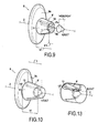
- the device 1 'shown in FIG. figure 11 differs from the device 1 in that it comprises two elongate elements 21,22.
- the first support piece 23 has a flat inner face 23a sufficient to be fixed in two different fastening zones 23b, 23c at the ends 21a, 22a of the first 21 and second 22 elements.
- Each elongated element 21, 22 has four locking pieces, preferably arranged as described above.
- the second support piece 24, at the figure 12 comprises a first 24a and a second 24b passage orifices to be slidably mounted at the same time respectively on the first 21 and the second 22 elongate elements.
- Opposite the first support piece 23, the free ends 21b, 22b of the elements 21, 22 are rigid and curved.
- the second support piece 24 comprises two frustoconical parts 25,26 projecting from its outer face 24c identical to the frustoconical piece 9 of the device 1 and each having in operation a band of the type of the strip 12.
- the practitioner successively passes the first element 21 and the second element 22 through the pillars of the diaphragm until the first support piece 23 abuts against a first pillar. Then he puts the second support piece 24 on the first 21 and second 22 elongate elements with the first 24a and second 24b through holes. Each of the locking pieces disposed along the length of the first 21 and second 22 elements is forced through the first 24a and second 24b through holes.
- the practitioner blocks the second support piece 24 with two pieces blocking devices arranged substantially at a distance of the same order from the first support 23.
- the second elongate element 22, like the first elongate element 21, does not shear the pillars and reinforces the clamping pressure exerted by the device 1 'and in particular the first 23 and second 24 support pieces.
- the device 1 'allows the use of support pieces 23,24 having greater bearing surfaces than those of the parts 3,8 of the device 1, and better balance the distribution of the tensions exerted by the first 21 and second 22 elongate elements between said parts 23,24.
- the frustoconical parts 25,26 each comprise a protector in the form of a tube in an adherent elastic material equivalent to the protector 12 of the device 1.
Abstract
Description
La présente invention concerne le domaine technique des dispositifs implantables pour le rapprochement de structures anatomiques fragiles, tels que les piliers du diaphragme dans le traitement de la hernie hiatale.The present invention relates to the technical field of implantable devices for the approximation of fragile anatomical structures, such as the diaphragm pillars in the treatment of hiatal hernia.
A l'état normal, l'orifice hiatal est traversé par le segment distal de l'oesophage accompagné des nerfs vague antérieur et postérieur. La jonction entre l'estomac et l'oesophage (cardia) est normalement située en dessous du diaphragme. Le muscle diaphragmatique sépare la cavité abdominale et la cavité thoracique. Il présente trois orifices qui permettent le passage de la veine cave, de l'aorte et de l'oesophage. L'orifice de passage de l'oesophage est dénommé orifice hiatal. Il est formé essentiellement par le piler diaphragmatique droit, avec une contribution plus faible du pilier gauche. Le pilier droit prend son origine au niveau du ligament vertébral longitudinal antérieur qui couvre les vertèbres lombaires.In the normal state, the hiatal opening is crossed by the distal segment of the esophagus accompanied by anterior and posterior vagus nerves. The junction between the stomach and the esophagus (cardia) is normally located below the diaphragm. The diaphragmatic muscle separates the abdominal cavity and the thoracic cavity. It has three orifices that allow the passage of the vena cava, the aorta and the esophagus. The passage opening of the esophagus is called the hiatal orifice. It is formed essentially by the right diaphragmatic pounder, with a smaller contribution from the left pillar. The right pillar originates from the anterior longitudinal vertebral ligament that covers the lumbar vertebrae.
Une hernie hiatale est provoquée par une altération de l'anatomie de l'orifice hiatal. Des structures anatomiques normalement confinées dans la cavité abdominale passent alors au travers dudit orifice déformé et se retrouvent en position intra-thoracique.A hiatal hernia is caused by an alteration of the anatomy of the hiatal orifice. Anatomical structures normally confined in the abdominal cavity then pass through said deformed orifice and are found in the intrathoracic position.
Quatre types de hernie hiatale peuvent alors survenir, répertoriées selon leur gravité croissante :
- le premier type est une hernie hiatale par glissement. L'orifice hiatal est élargi et la membrane phréno-oesophagienne distendue ce qui permet l'ascension de la jonction gastro-oesophagienne au dessus du diaphragme. La plupart des hernies de ce type sont asymptomatiques. Elles peuvent cependant entraîner l'apparition d'une maladie de reflux gastro-oesophagien par la perte de la compétence du mécanisme sphinctérien oesophagien inférieur.
- le second type est une hernie para-oesophagienne. La jonction gastro-oesophagienne demeure en place, mais la partie supérieure de l'estomac (fundus) migre vers le thorax au travers d'une zone de faiblesse de la membrane phréno-oesophagienne. Ce type de hernie peut entraîner des complications mécaniques ou vasculaires au niveau du bas oesophage ou de l'estomac hernié ;
- le troisième type est une hernie mixte. Elle combine des éléments des deux premiers types. Dans certains cas, la totalité de l'estomac peut se retrouver en position sus-diaphragmatique ;
- le quatrième type est caractérisé par un élargissement important de l'orifice diaphragmatique, permettant la herniation, non seulement de l'estomac, mais également d'autres structures abdominales (colon, rate).
- the first type is a sliding hiatal hernia. The hiatal opening is enlarged and the phrenoesophageal membrane distended allowing ascension of the gastro-oesophageal junction above the diaphragm. Most hernias of this type are asymptomatic. However, they can lead to the development of gastroesophageal reflux disease by losing the competence of the lower esophageal sphincter mechanism.
- the second type is a para-oesophageal hernia. The gastroesophageal junction remains in place, but the upper part of the stomach (fundus) migrates to the thorax through a zone of weakness of the phrenoesophageal membrane. This type of hernia may cause mechanical or vascular complications in the lower esophagus or herniated stomach;
- the third type is a mixed hernia. It combines elements of the first two types. In some cases, the entire stomach may be in an over-diaphragmatic position;
- the fourth type is characterized by a large enlargement of the diaphragmatic orifice, allowing herniation, not only of the stomach, but also of other abdominal structures (colon, spleen).
Le traitement d'une hernie hiatale, quel que soit le type de hernie, comporte la réduction de la hernie, c'est-à-dire le repositionnement des viscères herniés en dessous du diaphragme, et la plastie de l'orifice hiatal élargi.The treatment of a hiatal hernia, whatever the type of hernia, involves the reduction of the hernia, that is to say the repositioning of the herniated viscera below the diaphragm, and the plasty of the enlarged hiatal opening.
La plastie de l'orifice hiatal consiste en la recalibration de l'orifice hiatal autour de l'oesophage, sans comprimer mécaniquement l'oesophage tout en assurant une fermeture satisfaisante qui doit empêcher une récidive de la hernie. Cette réparation est appliquée sur une structure musculaire (piliers du diaphragme) qui n'a pas la résistance d'une structure aponévrotique et qui est sollicitée par des variations de pressions intra-abdominales (positives) et thoraciques (négatives).The plasty of the hiatal opening consists of the recalibration of the hiatal opening around the esophagus, without mechanically compressing the esophagus while ensuring a satisfactory closure which must prevent recurrence of the hernia. This repair is applied to a muscular structure (pillars of the diaphragm) that does not have the resistance of a fascial structure and is solicited by intra-abdominal (positive) and thoracic (negative) pressure variations.
La localisation de l'orifice hiatal (postérieure) accroît la difficulté du geste technique.The location of the hiatal (posterior) orifice increases the difficulty of the technical gesture.
Une première technique de plastie des hernies hiatales consiste à suturer avec des fils de suture non résorbables les piliers du diaphragme, en avant et/ou en arrière de l'oesophage. Des languettes, généralement en PTFE, peuvent être intercalées entre le fil de suture et les piliers du diaphragme pour éviter de cisailler les structures musculaires, cette technique de suture est alors appelée suture appuyée. Malgré cette précaution, on observe un effet de cisaillement des piliers gauche et droit, particulièrement avec la technique de suture simple. Cette première technique réalisée par laparoscopie rapporte des taux de récidive jusqu'à 42 % supérieurs aux taux de récidive observés dans la chirurgie conventionnelle, c'est-à-dire par laparotomie. Il n'existe pas d'étude randomisée comparant la suture simple et la suture appuyée. La différence des taux de récidive entre la chirurgie ouverte et la chirurgie laparoscopique laisse suspecter l'existence de difficultés techniques propres à la chirurgie laparoscopique.A first technique of plasty of hiatal hernias is to suture with nonabsorbable sutures the pillars of the diaphragm, forward and / or back of the esophagus. Tabs, usually made of PTFE, can be inserted between the suture and the diaphragm pillars to avoid shearing the muscle structures, this suture technique is then called suture supported. Despite this precaution, there is a shearing effect of the left and right abutments, particularly with the simple suture technique. This first technique performed by laparoscopy reports recurrence rates up to 42% higher than the recurrence rates observed in conventional surgery, that is to say by laparotomy. There is no randomized study comparing simple suture and supported suture. The difference in rates of recurrence between open surgery and laparoscopic surgery suggests the existence of technical difficulties specific to laparoscopic surgery.
Une seconde technique consiste à renforcer la suture des piliers en la recouvrant d'une prothèse qui entoure partiellement ou totalement l'oesophage. Pour être efficace, la prothèse est invariablement proche de la paroi de l'oesophage. Une étude réalisée sur une durée courte -6 mois- démontre un taux de récidive de 9% après renforcement au moyen d'une prothèse contre 24% pour la suture simple. Ces résultats favorables doivent être contre-balancés par la description de complications sévères liées à l'utilisation du matériel prothétique. Un contact direct entre la prothèse et la paroi de l'oesophage peut provoquer soit une réaction inflammatoire fibreuse qui entraîne une sténose de l'oesophage, soit une érosion progressive de la paroi oesophagienne avec pénétration de la prothèse dans la lumière de l'oesophage. Ces complications nécessitent une reprise chirurgicale pouvant aller jusqu'à la résection de l'oesophage. La probabilité d'observer ces complications est majorée par le fait que le contact prothèse-oesophage est dynamique, entre les mouvements respiratoires du diaphragme et les mouvements péristaltiques de l'oesophage, non synchronisés.A second technique involves strengthening the suture of the pillars by covering it with a prosthesis that partially or totally surrounds the esophagus. To be effective, the prosthesis is invariably close to the wall of the esophagus. A study carried out over a short period of 6 months demonstrates a recurrence rate of 9% after reinforcement with a prosthesis compared to 24% for simple suture. These favorable results must be counterbalanced by the description of severe complications related to the use of prosthetic equipment. Direct contact between the prosthesis and the wall of the esophagus can cause either a fibrous inflammatory reaction that causes stenosis of the esophagus, or progressive erosion of the esophageal wall with penetration of the prosthesis into the lumen of the esophagus. These complications require surgical revision up to resection of the esophagus. The probability of observing these complications is increased by the fact that prosthesis-esophageal contact is dynamic, between the respiratory movements of the diaphragm and the peristaltic movements of the esophagus, which are not synchronized.
Une troisième technique consiste à disposer une prothèse sur l'orifice hiatal sans tension, c'est-à-dire sans suture préalable des piliers. Aucun suivi à long terme n'a été rapporté à ce jour sur cette dernière technique.A third technique is to have a prosthesis on the hiatal orifice without tension, that is to say without prior suture of the pillars. No long-term follow-up has been reported to date on this latter technique.
De nombreuses études ont démontré que la récidive de la hernie hiatale est la cause principale d'échec du traitement chirurgical du reflux gastro-oesophagien et de la hernie hiatale. Elle est à l'origine de la majorité des reprises chirurgicales. La récidive est provoquée par la rupture, la distension ou une malfaçon de la plastie crurale.Numerous studies have shown that recurrence of hiatal hernia is the main cause of failure of surgical treatment of gastroesophageal reflux and hiatus hernia. She is at the origin of the majority of surgical revisions. Recurrence is caused by rupture, distention or malfunction of the crural plasty.
Trois facteurs doivent être pris en considération lors du traitement d'une hernie hiatale :
- la longueur de l'oesophage. Elle doit être suffisante pour permettre le repositionnement sans tension de la jonction gastro-oesophagienne sous le diaphragme ;
- la qualité des piliers du diaphragme. En cas de hernie volumineuse, les piliers peuvent être très écartés et réduits à deux fines bandes musculaires fragiles ;
- la qualité de la plastie de l'orifice hiatal. 90 à 95% des hernies observées dans la maladie de reflux gastro-oesophagien sont des hernies du premier type décrit ci-dessus et donc de petite taille, avec conservation d'une musculature satisfaisante. La situation anatomique de l'orifice hiatal peut rendre difficile un geste de suture laparoscopique dont la qualité dépend significativement de l'expérience de l'opérateur.
- the length of the esophagus. It must be sufficient to allow tension-free repositioning of the gastroesophageal junction under the diaphragm;
- the quality of the pillars of the diaphragm. In case of bulging hernia, the pillars can be widely separated and reduced to two thin fragile muscle bands;
- the quality of a plasty of a hiatal opening. 90 to 95% of hernias observed in gastro-oesophageal reflux disease are hernias of the first type described above and therefore of small size, with preservation of a satisfactory musculature. The anatomical situation of the hiatal orifice can make difficult a laparoscopic suture gesture whose quality depends significantly on the experience of the operator.
La présente invention a pour objet un dispositif implantable palliant les problèmes précités pour le rapprochement de structures anatomiques fragiles, notamment de structures musculaires telles que la paroi abdominale , les piliers du diaphragme dans le traitement de la hernie hiatale, le coeur, l'estomac ou l'utérus, ou de structures parenchymateuses telles que les reins, le foie et les poumons, comprenant au moins un premier élément longiligne de rapprochement d'au moins deux desdites structures anatomiques comportant sur sa longueur une première pièce d'appui, fixe ou fixable dans une position donnée dudit premier élément, au moins une pièce de blocage fixée à une distance donnée D de ladite première pièce d'appui dans ladite position, et une seconde pièce d'appui qui est apte à coulisser sur la longueur dudit élément longiligne en sorte que, lors de l'implantation, ladite pièce de blocage est forcée à travers ladite seconde pièce d'appui et vient en butée contre ladite seconde pièce d'appui, les première et seconde pièces d'appui délimitant entre elles un espace ayant au moins une dimension D' inférieure ou égale à D et apte à recevoir et enserrer lesdites structures anatomiques. La seconde pièce d'appui présente un premier orifice permettant le passage du premier élément longiligne et comporte une première pièce tronconique creuse ayant des découpes formant des ailettes latérales et ayant un évidement central qui prolonge ledit premier orifice de passage, le diamètre de sortie de l'évidement de la première pièce tronconique étant inférieur à l'encombrement de ladite pièce de blocage en sorte que le passage à force de ladite pièce de blocage à travers la seconde pièce d'appui est obtenu grâce à la déformation radiale des ailettes. La première pièce tronconique est pourvue d'un protecteur ayant une largeur de l'ordre de la hauteur de ladite pièce tronconique, éventuellement majorée de tout ou partie de la hauteur de ladite pièce de blocage, et apte à être disposé en fonctionnement sur la première pièce tronconique, et éventuellement ladite pièce de blocage, en sorte de recouvrir au moins lesdites découpes latérales.The present invention relates to an implantable device overcoming the aforementioned problems for the approximation of fragile anatomical structures, including muscle structures such as the abdominal wall, the pillars of the diaphragm in the treatment of hiatal hernia, heart, stomach or the uterus, or parenchymal structures such as the kidneys, the liver and the lungs, comprising at least a first elongate member for bringing together at least two of said anatomical structures having along its length a first support piece, fixed or fixable in a given position of said first element, at least one locking piece fixed at a given distance D of said first support piece in said position, and a second support piece which is able to slide along the length of said elongate element in so that, during implantation, said locking piece is forced through said second support piece and abuts against said second support piece, the first and second support members delimiting between them a space having at least one dimension D less than or equal to D and adapted to receive and enclose said anatomical structures. The second bearing piece has a first orifice allowing passage of the first elongate member and comprises a first hollow frustoconical piece having cutouts forming lateral fins and having a central recess which extends said first passage opening, the the outlet diameter of the recess of the first frustoconical part being smaller than the bulk of said locking piece so that the forced passage of said locking piece through the second support piece is obtained thanks to the radial deformation fins. The first frustoconical piece is provided with a protector having a width of the order of the height of said frustoconical piece, optionally increased by all or part of the height of said locking piece, and able to be arranged in operation on the first frustoconical piece, and possibly said locking piece, so as to cover at least said lateral cutouts.
On entend par structure anatomique fragile, toute structure anatomique à l'exception des os, et en particulier les structures musculaires et parenchymateuses.By fragile anatomical structure is meant any anatomical structure with the exception of the bones, and in particular the muscular and parenchymal structures.
Le premier orifice permet à la seconde pièce d'appui de coulisser librement sur la longueur dudit premier élément longiligne.The first port allows the second support piece to slide freely along the length of said first elongate member.
La première pièce tronconique s'étend de préférence de la face extérieure de ladite seconde pièce d'appui de sorte que celle-ci conserve une face intérieure sensiblement plane pour ne pas cisailler les structures anatomiques.The first frustoconical piece preferably extends from the outer face of said second support piece so that it retains a substantially flat inner face so as not to shear the anatomical structures.
Le protecteur évite que le premier élément longiligne, et éventuellement la pièce de blocage, ne passent à travers l'une des découpes latérales lors du passage en force de ladite pièce de blocage occasionnant la déformation desdites ailettes ou une fois le dispositif implanté, et ne viennent en contact avec la surface extérieure des structures anatomiques afin d'éviter tout risque de cisaillement et gêner la manipulation du dispositif par le praticien.The protector prevents the first elongate element, and possibly the locking piece, from passing through one of the lateral cutouts during the force passage of said locking piece causing the deformation of said fins or once the implanted device, and not come into contact with the outer surface of the anatomical structures to avoid any risk of shearing and interfere with the handling of the device by the practitioner.
La pièce de blocage, en particulier lorsqu'elle comporte une extrémité amincie voire pointue, est de préférence recouverte par ledit protecteur pour éviter de perforer des structures anatomiques voisines.The locking piece, in particular when it has a thinned or pointed end, is preferably covered by said protector to avoid perforating neighboring anatomical structures.
S'agissant des piliers du diaphragme qui sont des structures anatomiques très tendres et fragiles, en particulier parce que les fibres des muscles sont toutes orientées dans la direction longitudinale des piliers, compte tenu de la zone d'implantation soumise aux mouvements du diaphragme (environ 2500 pulsations du diaphragme par jour), la demanderesse a observé que, sans protecteur, si le premier élément longiligne et éventuellement la pièce de blocage passent à travers une découpe latérale et viennent en contact avec le pilier recevant la seconde pièce d'appui, ce pilier est cisaillé transversalement par ces derniers et le rapprochement des piliers opéré grâce au dispositif est alors nul. Le protecteur empêche ainsi tout cisaillement des piliers du diaphragme et permet que le rapprochement des piliers opéré par le dispositif selon l'invention soit parfaitement stable.Regarding the pillars of the diaphragm which are very tender and fragile anatomical structures, in particular because the muscle fibers are all oriented in the longitudinal direction of the pillars, taking into account the implantation area subjected to the movements of the diaphragm (approximately 2500 pulsations of the diaphragm per day), the Applicant has observed that, without a protector, if the first elongate element and possibly the locking piece pass through a lateral cut and come into contact with the pillar receiving the second support piece, the pillar is sheared transversely by the latter and the bringing together of the pillars operated by the device is then zero . The protector thus prevents any shearing of the pillars of the diaphragm and allows that the approach of the pillars operated by the device according to the invention is perfectly stable.
Contrairement aux techniques de sutures simples et appuyées encerclant en partie au moins deux structures anatomiques, telles que les piliers gauche et droit, l'élément longiligne traverse lesdites structures anatomiques, lesquelles sont maintenues entre les première et seconde pièces d'appui. Il n'y a pas de fil de suture venant en appui sur la surface extérieure desdites structures anatomiques, ce qui élimine les risques de cisailler ces derniers qui sont des structures fragiles, particulièrement en ce qui concerne les piliers du diaphragme qui sont des muscles « tendres ». Lesdites structures anatomiques, par exemple les piliers, sont enserrées entre les pièces d'appui bloquées et distantes selon une distance déterminée D' inférieure ou égale à D de sorte que le praticien connaît précisément la distance selon laquelle il a rapproché lesdites structures anatomiques augmentant ainsi la précision de la technique opératoire.Unlike simple and supported suture techniques partially encircling at least two anatomical structures, such as left and right abutments, the elongate member traverses said anatomical structures, which are held between the first and second support pieces. There is no suture bearing on the outer surface of said anatomical structures, which eliminates the risk of shearing the latter which are fragile structures, particularly with regard to the pillars of the diaphragm which are muscles. tender ". Said anatomical structures, for example the pillars, are sandwiched between the support pieces locked and distant at a determined distance D less than or equal to D so that the practitioner knows precisely the distance by which he has brought said anatomical structures together thus increasing. the precision of the operative technique.
Dans le cas du traitement de la hernie hiatale, le dispositif une fois implanté ne comporte pas de bords extérieurs susceptibles d'entrer en contact avec la paroi oesophagienne. Le dispositif est facile à mettre en place contrairement aux prothèses et sutures utilisés dans l'état de la technique ce qui diminue les risques post-opératoires de récidive. De plus, ledit dispositif étant peu encombrant peut être implanté facilement par laparoscopie. Les piliers gauche et droit viennent en appui contre les faces intérieures des première et seconde pièces d'appui et sont retenus dans leur position resserrée entre ces dernières. Il est bien sûr possible d'implanter le dispositif selon la présente invention par laparotomie.In the case of treatment of the hiatal hernia, the device once implanted has no external edges likely to come into contact with the esophageal wall. The device is easy to implement unlike the prostheses and sutures used in the state of the art which reduces the post-operative risk of recurrence. In addition, said device being compact can be easily implanted by laparoscopy. The left and right pillars abut against the inner faces of the first and second support pieces and are retained in their narrowed position between them. It is of course possible to implant the device according to the present invention by laparotomy.
La première pièce d'appui et la ou les pièces de blocage sont fixées ou fixables sur la longueur dudit élément longiligne par n'importe quels moyens mécaniques ou chimiques connus de l'état de la technique : clipsage, collage, soudures ultrasons ou haute fréquences..., ou encore en réalisant un noeud sur lui-même dudit élément longiligne faisant office de pièce de blocage ou de butée arrière pour ladite première pièce d'appui.The first support piece and the one or more locking pieces are fixed or fixable along the length of said elongated element by any means mechanical or chemical known from the state of the art: clipping, gluing, ultrasonic or high frequency welding ..., or by making a knot on itself of said elongate member acting as a locking piece or rear stop for said first piece of support.
Dans une variante, les première et seconde pièces d'appui ont au moins une face intérieure sensiblement plane, de préférence ladite face intérieure a une forme générale d'ellipse.Alternatively, the first and second support members have at least one substantially planar inner face, preferably said inner face has a generally elliptical shape.
Les faces intérieures planes des première et seconde pièces d'appui sont plaquées contre les structures anatomiques, de sorte qu'elles ne peuvent cisailler la structure musculaire fibreuse de ces dernières lorsqu'il s'agit de muscles, en particulier des piliers du diaphragme.The flat inner faces of the first and second support members are pressed against the anatomical structures, so that they can not shear the fibrous muscle structure of the latter when it comes to muscles, particularly the pillars of the diaphragm.
De préférence, la première pièce d'appui a une forme générale sensiblement plane.Preferably, the first support piece has a substantially flat overall shape.
Dans une variante, le dispositif comprend un second élément longiligne de rapprochement desdites structures anatomiques, la première pièce d'appui étant fixe ou fixable dans une position donnée dudit second élément, et au moins une pièce de blocage fixée sur la longueur dudit second élément à une distance donnée D de ladite première pièce d'appui dans ladite position, la seconde pièce d'appui étant apte à coulisser sur la longueur dudit second élément longiligne en sorte que, lors de l'implantation, ladite pièce de blocage est forcée à travers ladite seconde pièce d'appui et vient en butée contre ladite seconde pièce d'appui.In a variant, the device comprises a second elongate member for approximating said anatomical structures, the first support piece being fixed or fixable in a given position of said second element, and at least one locking piece fixed on the length of said second element to a given distance D of said first support piece in said position, the second support piece being able to slide along the length of said second elongate element so that, during implantation, said locking piece is forced through said second support piece and abuts against said second support piece.
La seconde pièce d'appui est apte à coulisser à la fois sur le premier élément longiligne et sur le second élément longiligne.The second support piece is able to slide both on the first elongate element and on the second elongate element.
L'emploi d'un second élément longiligne permet de renforcer la pression exercée de part et d'autre desdites structures anatomiques respectivement par les première et seconde pièces d'appui.The use of a second elongate element makes it possible to reinforce the pressure exerted on either side of said anatomical structures respectively by the first and second support pieces.
Le second élément traverse également lesdites structures anatomiques de sorte qu'il ne peut cisailler leurs surfaces extérieures.The second element also passes through said anatomical structures so that it can not shear their outer surfaces.
Lorsque les structures anatomiques sont les deux piliers du diaphragme, le choix du nombre d'élément longiligne est fonction du renfort à apporter à la plastie du hiatus oesophagien et du type de hernie hiatale.When the anatomical structures are the two pillars of the diaphragm, the choice of the number of elongated element is a function of the reinforcement to be made to the plasty of the esophageal hiatus and the type of hiatal hernia.
Dans une variante, le premier, et éventuellement le second, élément longiligne comporte plusieurs pièces de blocage successives, de préférence ayant une hauteur du même ordre, à des distances prédéterminées D de ladite première pièce d'appui, de préférence la distance D est comprise dans l'intervalle [10 ; 25] mm.In a variant, the first, and possibly the second, elongated element comprises several successive locking pieces, preferably having a height of the same order, at predetermined distances D of said first support piece, preferably the distance D is included in the range [10; 25] mm.
Le premier, et éventuellement le second, élément longiligne comporte de préférence quatre pièces de blocage, la première étant à une distance D de préférence de l'ordre de 10 mm de la première pièce d'appui, les pièces de blocage suivantes étant espacées les unes des autres de préférence de l'ordre de 5 mm à compter de ladite première pièce de blocage. Les pièces de blocage sont autant de repère pour le praticien pour bloquer la seconde pièce d'appui et déterminer précisément la distance D' selon laquelle les structures anatomiques sont rapprochées ce qui n'était pas possible avec les sutures et orthèses mis en oeuvre dans l'état de la technique, particulièrement pour le traitement de la hernie hiatale.The first, and possibly the second, elongated element preferably comprises four locking pieces, the first being at a distance D preferably of the order of 10 mm from the first support piece, the following locking pieces being spaced the each other preferably of the order of 5 mm from said first blocking part. The locking pieces are as much a reference for the practitioner to block the second support piece and precisely determine the distance D 'according to which the anatomical structures are close together, which was not possible with the sutures and orthoses used in the treatment. state of the art, particularly for the treatment of hiatal hernia.
Les pièces de blocage disposées sur les premier et second éléments longilignes sont de préférence à égales distances de ladite première pièce d'appui de sorte que le praticien force deux pièces de blocage à la fois à travers la seconde pièce d'appui en sorte de former un espace délimité entre les première et seconde pièces d'appui ayant au moins une dimension D' sensiblement constante.The locking pieces disposed on the first and second elongate members are preferably at equal distances from said first support piece so that the practitioner forces two locking pieces at a time through the second support piece so as to form a space defined between the first and second support members having at least one dimension D 'substantially constant.
La hauteur d'une pièce de blocage correspond à la longueur d'une portion de premier, ou de second, élément longiligne selon laquelle ladite pièce est fixée. De préférence, les pièces de blocage sont identiques et présentent une hauteur du même ordre.The height of a locking piece corresponds to the length of a portion of first or second elongate element in which said piece is fixed. Preferably, the locking pieces are identical and have a height of the same order.
Dans une variante, la seconde pièce d'appui présente un second orifice permettant le passage dudit second élément longiligne.In a variant, the second support piece has a second orifice allowing the passage of said second elongate element.
Le second orifice permet à la seconde pièce d'appui de coulisser librement sur la longueur dudit second élément longiligne.The second port allows the second support piece to slide freely along the length of said second elongate member.
Dans une variante, la seconde pièce d'appui comporte une seconde pièce tronconique creuse, ayant des découpes formant des ailettes latérales et ayant un évidement central qui prolonge le second orifice de passage. Le diamètre de sortie de l'évidement de ladite seconde pièce tronconique est inférieur à l'encombrement de la pièce de blocage, en sorte que le passage en force de la pièce de blocage à travers la seconde pièce d'appui est obtenu grâce à la déformation radiale des ailettes.In a variant, the second support piece comprises a second hollow frustoconical part having cutouts forming lateral fins and having a central recess which extends the second passage opening. The outlet diameter of the recess of said second frustoconical piece is smaller than the size of the blocking piece, so that the force passage of the blocking piece through the second piece of support is obtained thanks to the radial deformation of the fins.
La seconde pièce tronconique creuse s'étend de préférence de la face extérieure de ladite seconde pièce d'appui de sorte que celle-ci conserve une face intérieure sensiblement plane pour ne pas cisailler les structures anatomiques.The second hollow frustoconical piece preferably extends from the outer face of said second support piece so that it retains a substantially flat inner face so as not to shear the anatomical structures.
Dans une variante, la première, et éventuellement la seconde, pièce tronconique creuse comporte un épaulement interne dans sa portion d'extrémité formant un logement apte à recevoir tout ou partie de la hauteur d'une pièce de blocage.In a variant, the first, and possibly the second, hollow frustoconical part has an internal shoulder in its end portion forming a housing adapted to receive all or part of the height of a locking piece.
Selon la profondeur de l'épaulement interne, tout ou partie de la hauteur de la pièce de blocage est logée à l'intérieur de la première, ou de la seconde, pièce tronconique et ce dans l'évidement central.Depending on the depth of the internal shoulder, all or part of the height of the locking piece is housed inside the first, or second, frustoconical piece and in the central recess.
Les découpes latérales sont ainsi en partie, ou totalement selon la profondeur de l'épaulement, obturées par la pièce de blocage en sorte que l'élément longiligne ne puisse passer à travers lesdites ailettes et cisailler des structures anatomiques environnantes.The lateral cutouts are thus partly, or totally according to the depth of the shoulder, closed by the locking piece so that the elongated member can pass through said fins and shear surrounding anatomical structures.
Dans une variante, ladite seconde pièce tronconique est pourvue d'un protecteur ayant une largeur de l'ordre de la hauteur de ladite seconde pièce tronconique, éventuellement majorée de tout ou partie de la hauteur de l'une des pièces de blocage, et apte à être disposée en fonctionnement sur ladite seconde pièce tronconique et éventuellement ladite pièce de blocage, en sorte de recouvrir au moins lesdites découpes latérales.In a variant, said second frustoconical piece is provided with a protector having a width of the order of the height of said second frustoconical piece, optionally increased by all or part of the height of one of the locking pieces, and capable of to be disposed in operation on said second frustoconical piece and possibly said locking piece, so as to cover at least said lateral cutouts.
Lorsque le dispositif comprend deux éléments longilignes, la seconde pièce d'appui comprend de préférence deux pièces tronconiques telles que décrites ci-dessus et deux desdits protecteurs, chacun étant apte à être disposé en fonctionnement sur les pièces tronconiques.When the device comprises two elongated elements, the second support piece preferably comprises two frustoconical parts as described above and two of said protectors, each being able to be arranged in operation on the frustoconical parts.
De préférence, la largeur du protecteur est déterminée en sorte qu'il recouvre à la fois les découpes latérales et tout ou partie de la hauteur de la pièce de blocage sélectionnée. Lorsque la première, et éventuellement la seconde, pièce tronconique comporte un épaulement interne, la largeur du protecteur correspond à la hauteur de ladite pièce tronconique majorée de la hauteur de la pièce de blocage moins la profondeur dudit épaulement. Cette disposition permet que la pièce de blocage, en particulier lorsqu'elle comporte une extrémité amincie voire pointue, soit recouverte par ledit protecteur pour éviter de perforer des structures anatomiques voisines.Preferably, the width of the protector is determined so that it covers both the side cuts and all or part of the height of the piece blocking selected. When the first, and possibly the second, frustoconical piece has an internal shoulder, the width of the protector corresponds to the height of said frustoconical piece plus the height of the locking piece minus the depth of said shoulder. This arrangement allows the locking piece, in particular when it has a thinned or even pointed end, to be covered by said protector to avoid perforating neighboring anatomical structures.
Ce protecteur évite que le second élément longiligne, et éventuellement la pièce de blocage, ne passent à travers l'une des découpes latérales et ne viennent en contact avec la surface extérieure des structures anatomiques afin d'éviter tout risque de cisaillement.This protector prevents the second elongate element, and possibly the locking piece, from passing through one of the lateral cutouts and does not come into contact with the outer surface of the anatomical structures in order to avoid any risk of shearing.
Dans une variante, le protecteur de la première pièce tronconique creuse, et éventuellement le protecteur de la seconde pièce tronconique creuse, consiste dans une bande dans un matériau élastique, de préférence à base de silicone.In a variant, the protector of the first hollow frustoconical part, and possibly the protector of the second hollow frustoconical part, consists of a strip made of an elastic material, preferably based on silicone.
Le protecteur peut être maintenu sur la première pièce tronconique simplement par sa force élastique ou collé, de préférence selon sa base sur la face extérieure de la seconde pièce d'appui correspondant à sa face non orientée en fonctionnement vers les structures anatomiques à rapprocher.The protector may be held on the first frustoconical piece simply by its elastic force or glued, preferably according to its base on the outer face of the second support piece corresponding to its non-oriented face in operation towards the anatomical structures to be brought together.
Le protecteur, bien que plaqué contre la pièce tronconique en sorte de recouvrir au moins lesdites découpes latérales de cette dernière, est suffisamment élastique afin de permettre aux ailettes latérales de se déformer radialement lors du passage en force de la pièce de blocage à travers l'orifice de passage.The protector, although pressed against the frustoconical piece so as to cover at least said lateral cutouts of the latter, is sufficiently elastic in order to allow the lateral fins to deform radially when the blocking piece is forced through the hole. passage opening.
Le protecteur peut ainsi être sélectionné indépendamment des autres pièces du dispositif (première et seconde pièces d'appui, première et seconde pièces tronconiques), notamment de par sa largeur, en fonction de la hauteur de la pièce tronconique et/ou de la hauteur de la pièce de blocage.The protector can thus be selected independently of the other parts of the device (first and second support parts, first and second frustoconical parts), in particular by its width, as a function of the height of the frustoconical part and / or the height of the the blocking part.
Dans une variante, le premier, et éventuellement le second, élément longiligne est un monofilament, une tresse ou un câble rigide de faible diamètre, de préférence de l'ordre de 1,7 mm.In a variant, the first, and possibly the second, elongate element is a monofilament, a braid or a rigid cable of small diameter, preferably of the order of 1.7 mm.
Dans une variante, le premier, et éventuellement le second, élément longiligne présente une extrémité rigide et courbe permettant son introduction dans lesdites structures anatomiques, notamment à l'opposé de ladite première pièce d'appui.In a variant, the first, and possibly the second, elongated element has a rigid end and curve allowing its introduction in said anatomical structures, in particular opposite said first support piece.
La rigidité doit être suffisante pour que ladite extrémité puisse traverser lesdites structures anatomiques et notamment les piliers. Ladite extrémité peut être formée à partir du premier ou du second élément longiligne lui-même par enduction ou imprégnation d'un polymère implantable puis mise en forme, ou par fusion du ou des polymères formant le dit premier ou second élément à l'aide d'un solvant de ces derniers. Ladite extrémité peut être également formée en rapportant sur l'extrémité libre une pièce courbe et rigide implantable moulée.The rigidity must be sufficient for said end to pass through said anatomical structures including the pillars. Said end may be formed from the first or second elongate element itself by coating or impregnating an implantable polymer and then shaping, or by melting the polymer or polymers forming said first or second element using a solvent of these. Said end may also be formed by providing on the free end a molded curved and rigid molded piece.
Dans une variante, la ou les pièces de blocage ont une forme générale tronconique.In a variant, the locking piece or pieces have a generally frustoconical shape.
Dans une variante, les première et seconde pièces d'appui, la ou les pièces de blocage, la première pièce tronconique creuse, éventuellement la seconde pièce tronconique creuse, le protecteur de la première tronconique creuse, éventuellement le protecteur de la seconde pièce tronconique creuse, sont moulés, de préférence dans un polymère choisi parmi les polymères suivants : PEEK (polyétheréthercetone), POM (polyoxyméthylène), PET (polyéthylènetéréphtalate), PP (polypropylène), PE (polyéthylène).In a variant, the first and second support members, the one or more locking pieces, the first hollow frustoconical piece, optionally the second hollow frustoconical piece, the protector of the first hollow frustoconical, possibly the protector of the second hollow frustoconical piece. are molded, preferably in a polymer selected from the following polymers: PEEK (polyetheretherketone), POM (polyoxymethylene), PET (polyethylene terephthalate), PP (polypropylene), PE (polyethylene).
Ces différentes pièces sont moulées en même temps en sorte de former une pièce unique. Le protecteur, étant dans ce cas rigide, se présente sous la forme d'un cylindre s'étendant de la face de la seconde pièce d'appui non orientée en fonctionnement vers les structures anatomiques à rapprocher. De préférence, le protecteur recouvre au moins les découpes latérales de la pièce tronconique creuse sans entrer en contact direct avec ladite pièce tronconique et donc ses ailettes de sorte de ménager un espace libre, délimité entre ladite pièce tronconique et ledit protecteur, dans lequel lesdites ailettes peuvent se déformer radialement lors du passage en force de la pièce de blocage.These different pieces are molded at the same time so as to form a single piece. The protector, being in this case rigid, is in the form of a cylinder extending from the face of the second non-oriented support piece in operation towards the anatomical structures to be brought together. Preferably, the protector covers at least the lateral cutouts of the hollow frustoconical part without coming into direct contact with said frustoconical piece and thus its fins so as to provide a free space, delimited between said frustoconical piece and said protector, in which said fins can deform radially during the passage of force of the locking piece.
L'invention concerne selon un deuxième aspect un ensemble pour le rapprochement de structures anatomiques fragiles, notamment de structures musculaires telles que la paroi abdominale, les piliers du diaphragme dans le traitement de la hernie hiatale, le coeur, l'estomac ou l'utérus ou de structures parenchymateuses telles que les reins, le foie et les poumons comportant un dispositif implantable selon l'une des variantes de réalisation décrites ci-dessus et un kit d'implantation comprenant notamment un organe de traction et un poussoir.The invention relates to a second aspect an assembly for the approximation of fragile anatomical structures, including muscle structures such as the abdominal wall, the pillars of the diaphragm in the treatment of hiatal hernia, heart, stomach or uterus or structures parenchymatics such as kidneys, liver and lungs comprising an implantable device according to one of the embodiments described above and an implantation kit comprising in particular a traction member and a pusher.
L'invention concerne selon un troisième aspect, l'utilisation d'un ou plusieurs dispositifs implantables selon l'une des variantes de réalisation décrites ci-dessus, pour le rapprochement de structures musculaires telles que la paroi abdominale, le diaphragme, le coeur, l'estomac ou l'utérus.The invention relates to a third aspect, the use of one or more implantable devices according to one of the embodiments described above, for the approximation of muscle structures such as the abdominal wall, the diaphragm, the heart, the stomach or the uterus.
L'invention concerne selon un quatrième aspect, l'utilisation d'un ou plusieurs dispositifs implantables selon l'une des variantes de réalisation décrites ci-dessus, pour le rapprochement de structures parenchymateuses telles que les reins, le foie et les poumons.The invention relates in a fourth aspect, the use of one or more implantable devices according to one of the embodiments described above, for the approximation of parenchymal structures such as the kidneys, liver and lungs.
L'invention sera mieux comprise, grâce à la description ci-après, qui se rapporte à deux modes de réalisation préférés, donné à titre d'exemples non limitatifs, et expliqués avec références aux dessins schématiques annexés, dans lesquels :
- la
figure 1A est une représentation schématique en perspective et vue de côté d'un premier exemple de dispositif selon la présente invention ; - la
figure 1B est une représentation schématique en perspective et vue de côté de la seconde pièce d'appui représentée à lafigure 1A ; - la
figure 1C est une représentation schématique vue selon la face intérieure de la seconde pièce d'appui représentée à lafigure 1B ; - la
figure 1D est une représentation schématique vue de coté du protecteur de la pièce tronconique de la seconde pièce d'appui représentée auxfigures 1B et 1C ; - la
figure 2 est une représentation schématique d'une hernie hiatale du second type ; - les
figures 3 à 8 sont des représentations schématiques des différentes étapes pour l'implantation du dispositif décrit auxfigures 1A, 1B et 2 ; - les
figures 9 et 10 sont des représentations schématiques en perspective d'une variante de la pièce tronconique représentée auxfigures 1B-1D ; - les
figures 11 et 12 sont des représentations schématiques vues de côté d'un second mode de réalisation du dispositif selon la présente invention. - la
figure 13 est une représentation schématique en perspective d'une variante du protecteur représenté à lafigure 10 .
- the
Figure 1A is a schematic perspective view and side view of a first exemplary device according to the present invention; - the
Figure 1B is a schematic representation in perspective and side view of the second support piece shown in FIG.Figure 1A ; - the
figure 1C is a schematic representation seen along the inside of the second support piece shown in FIG.Figure 1B ; - the
figure 1D is a diagrammatic representation seen from the side of the protector of the frustoconical piece of the second support piece shown in FIGS.Figures 1B and 1C ; - the
figure 2 is a schematic representation of a hiatal hernia of the second type; - the
Figures 3 to 8 are schematic representations of the different steps for the implementation of the device described inFigures 1A, 1B and2 ; - the
Figures 9 and 10 are diagrammatic representations in perspective of a variant of the frustoconical piece represented inFigures 1B-1D ; - the
Figures 11 and 12 are schematic side views of a second embodiment of the device according to the present invention. - the
figure 13 is a schematic representation in perspective of a variant of the protector shown in FIG.figure 10 .
Le dispositif implantable 1 représenté à la
Le dispositif 1 comprend une seconde pièce d'appui 8, représentée à la
Le dispositif 1 ainsi implanté est parfaitement maintenu en tension par la dite pièce de blocage 4, laquelle maintient également les faces intérieures planes 3a,8b contre les piliers fibreux 15,16. Le dispositif 1 ne comporte pas de partie susceptible de cisailler la surface extérieure des piliers 15,16. Les piliers 15,16 sont maintenus rapprochés durablement.The
La pièce tronconique 9' représentée aux
La pièce tronconique 9' comporte un épaulement interne 9'a ayant une profondeur h1' dans sa portion d'extrémité 9b formant un logement apte à recevoir une partie de la hauteur h4,h5,h6,h7 de l'une des pièces de blocage 4,5,6,7. La largeur l1' de la bande 12' est de l'ordre de celle de la hauteur h1 de la pièce tronconique 9' majorée de la hauteur h4,h5,h6,h7 moins la profondeur h1' de l'épaulement interne 9a en sorte qu'en fonctionnement (tel que représenté en partie à la
De préférence, les première 3 et seconde 8 pièces d'appui, y compris les pièces tronconiques 9,9' ainsi que les pièces de blocage 4,5,6,7 sont moulées, de préférence dans un polymère choisi parmi les polymères suivants : PEEK (polyétherétherkétone), POM (polyoxyméthylène), PET (polyéthylènetéréphtalate), PP (polypropylène), PE (polyéthylène).Preferably, the first 3 and second 8 bearing parts, including the
Le protecteur 12" représenté à la
Le dispositif 1' représenté à la
En fonctionnement, le praticien passe successivement le premier élément 21 puis le second élément 22 à travers les piliers du diaphragme jusqu'à ce que la première pièce d'appui 23 vienne en butée contre un premier pilier. Puis il enfile la seconde pièce d'appui 24 sur les premier 21 et second 22 éléments longilignes à l'aide des premier 24a et second 24b orifices de passage. Chacune des pièces de blocage disposées sur la longueur des premier 21 et second 22 éléments est forcée à travers les premier 24a et second 24b orifices de passage. De préférence, afin d'obtenir un espace délimité par une dimension sensiblement constante, correspondant à l'écartement entre les première 23 et seconde 24 pièces d'appui, le praticien bloque la seconde pièce d'appui 24 à l'aide de deux pièces de blocage disposées sensiblement à une distance du même ordre de la première d'appui 23.In operation, the practitioner successively passes the
Le second élément longiligne 22, tout comme le premier élément longiligne 21, ne cisaille pas les piliers et renforce la pression de serrage exercée par le dispositif 1' et notamment les première 23 et seconde 24 pièces d'appui. Le dispositif 1' permet l'emploi de pièces d'appui 23,24 ayant des surfaces d'appui plus importantes que celles des pièces 3,8 du dispositif 1, et de mieux équilibrer la répartition des tensions exercées par les premier 21 et second 22 éléments longilignes entre lesdites pièces 23,24.The second
De préférence, les pièces tronconiques 25,26 comportent chacune un protecteur se présentant sous la forme d'un tube dans un matériau élastique adhérent équivalent au protecteur 12 du dispositif 1.Preferably, the
Bien sûr, selon la pathologie, il est possible d'implanter un ou plusieurs dispositifs 1 décrits aux
Claims (14)
Applications Claiming Priority (1)
| Application Number | Priority Date | Filing Date | Title |
|---|---|---|---|
| FR0851862A FR2928826B1 (en) | 2008-03-21 | 2008-03-21 | IMPLANTABLE DEVICE |
Publications (2)
| Publication Number | Publication Date |
|---|---|
| EP2103261A1 true EP2103261A1 (en) | 2009-09-23 |
| EP2103261B1 EP2103261B1 (en) | 2011-01-05 |
Family
ID=39789296
Family Applications (1)
| Application Number | Title | Priority Date | Filing Date |
|---|---|---|---|
| EP20090155739 Expired - Fee Related EP2103261B1 (en) | 2008-03-21 | 2009-03-20 | Implantable device |
Country Status (4)
| Country | Link |
|---|---|
| EP (1) | EP2103261B1 (en) |
| DE (1) | DE602009000508D1 (en) |
| ES (1) | ES2361470T3 (en) |
| FR (1) | FR2928826B1 (en) |
Families Citing this family (1)
| Publication number | Priority date | Publication date | Assignee | Title |
|---|---|---|---|---|
| RU2482801C2 (en) * | 2011-07-19 | 2013-05-27 | Владимир Иванович Белоконев | Method of diaphragm plasty in case of post-trauma diaphragmatic hernia |
Citations (7)
| Publication number | Priority date | Publication date | Assignee | Title |
|---|---|---|---|---|
| US4326531A (en) * | 1978-09-20 | 1982-04-27 | Olympus Optical Co., Ltd. | Device for operating a coeliac tubular member-closing implement |
| US5370661A (en) * | 1990-11-06 | 1994-12-06 | Branch; Thomas P. | Method and apparatus for re-approximating tissue |
| WO2005016176A2 (en) * | 2003-08-07 | 2005-02-24 | Leiboff Arnold R | Device and method for tacking a prosthetic screen |
| WO2007002071A1 (en) * | 2005-06-21 | 2007-01-04 | Ams Research Corporation | Apparatus for securing a urethral sling to pubic bone |
| FR2889441A1 (en) | 2005-08-04 | 2007-02-09 | Microval Sa | REINFORCING PROSTHESIS IN THE FORM OF A TEXTILE STRUCTURE |
| US20070049971A1 (en) * | 2005-06-09 | 2007-03-01 | Sing-Fatt Chin | Method and apparatus for closing off a portion of a heart ventricle |
| WO2007067206A2 (en) * | 2005-05-10 | 2007-06-14 | Michael Gertner | Obesity treatment systems |
-
2008
- 2008-03-21 FR FR0851862A patent/FR2928826B1/en not_active Expired - Fee Related
-
2009
- 2009-03-20 ES ES09155739T patent/ES2361470T3/en active Active
- 2009-03-20 DE DE200960000508 patent/DE602009000508D1/en active Active
- 2009-03-20 EP EP20090155739 patent/EP2103261B1/en not_active Expired - Fee Related
Patent Citations (7)
| Publication number | Priority date | Publication date | Assignee | Title |
|---|---|---|---|---|
| US4326531A (en) * | 1978-09-20 | 1982-04-27 | Olympus Optical Co., Ltd. | Device for operating a coeliac tubular member-closing implement |
| US5370661A (en) * | 1990-11-06 | 1994-12-06 | Branch; Thomas P. | Method and apparatus for re-approximating tissue |
| WO2005016176A2 (en) * | 2003-08-07 | 2005-02-24 | Leiboff Arnold R | Device and method for tacking a prosthetic screen |
| WO2007067206A2 (en) * | 2005-05-10 | 2007-06-14 | Michael Gertner | Obesity treatment systems |
| US20070049971A1 (en) * | 2005-06-09 | 2007-03-01 | Sing-Fatt Chin | Method and apparatus for closing off a portion of a heart ventricle |
| WO2007002071A1 (en) * | 2005-06-21 | 2007-01-04 | Ams Research Corporation | Apparatus for securing a urethral sling to pubic bone |
| FR2889441A1 (en) | 2005-08-04 | 2007-02-09 | Microval Sa | REINFORCING PROSTHESIS IN THE FORM OF A TEXTILE STRUCTURE |
Also Published As
| Publication number | Publication date |
|---|---|
| FR2928826B1 (en) | 2011-04-15 |
| ES2361470T3 (en) | 2011-06-17 |
| DE602009000508D1 (en) | 2011-02-17 |
| EP2103261B1 (en) | 2011-01-05 |
| FR2928826A1 (en) | 2009-09-25 |
Similar Documents
| Publication | Publication Date | Title |
|---|---|---|
| EP1033946B1 (en) | Device for fixing a prosthesis for treating groin hernias by celioscopy | |
| EP2334256B1 (en) | Surgical instrument for deploying a prosthesis | |
| EP2068756A2 (en) | Suburethral hammock | |
| EP1406543A1 (en) | Kit comprising a medical fixing element and a device for placing said fixing element | |
| FR2762989A1 (en) | SYSTEM FOR REPAIRING AN ANATOMIC DUCT BY A PROGRESSIVE OPENING IMPLANT | |
| FR2900814A1 (en) | Intervertebral cage implantation instrument for use by practitioner, has pusher that translates cage, and unit that guides cage during its displacement and with sleeve having inner section determined so that elementary cages are translated | |
| FR2929835A1 (en) | SURGICAL ATTACHMENT FOR ATTACHING A HERNIA PROSTHESIS | |
| WO2004091443A2 (en) | Implant for the treatment of a cystocele and device for placement of said implant | |
| EP2459122B1 (en) | Prosthetic ligament for transverse fixation, and production method | |
| EP2103261B1 (en) | Implantable device | |
| WO2018024617A1 (en) | Deployable implant | |
| CA2494586A1 (en) | Semi-automatic device for blocking and tensioning a surgical suture thread | |
| EP2451362B1 (en) | Implantable device for bringing together anatomical structures, in particular in hiatal hernia treatment | |
| FR2979229A1 (en) | ENDOPROTHESIS FENESTRATION DEVICE | |
| FR2964553A1 (en) | SURGICAL TREATMENT SYSTEM FOR REALIZING ANASTOMOSIS BETWEEN THE BLADDER AND THE URETRE | |
| FR2979228A1 (en) | UNIVERSAL AORTIC ENDOPROTHESIS | |
| FR2924596A1 (en) | Fixation device for ligamentoplasty, has hollow cage having outer wall terminated at level of upper end by threading or by smooth part having external diameter lesser than or equal to inner diameter of threading | |
| EP0941038B1 (en) | MEDICAL SET FOR INTERVENTION ON AN ANATOMICAL DUCT and appertaining SEALING RING | |
| EP2723250B1 (en) | Anastomotic device and method for manufacturing such a device | |
| EP2127614B1 (en) | Anchoring and guiding device, manufacturing method and associated implant | |
| FR2904527A1 (en) | Plastic surgical kit for repairing anterior cruciate ligament of knee, has strips maintained in femoral and tibial bone tunnels, where strips have specific mechanical traction resistance, and pull wire drawing strips across tunnels | |
| FR2919487A1 (en) | SURGICAL BAND REEL | |
| FR3123191A1 (en) | Anchor implant and surgical set for ligamentoplasty | |
| EP1800618B1 (en) | Surgical prosthesis forming device used to implant an organ support in a mammal | |
| FR3086524A1 (en) | DEVICE FOR FIXING AT LEAST ONE SUTURE THREAD IN A BIOLOGICAL TISSUE |
Legal Events
| Date | Code | Title | Description |
|---|---|---|---|
| PUAI | Public reference made under article 153(3) epc to a published international application that has entered the european phase |
Free format text: ORIGINAL CODE: 0009012 |
|
| AK | Designated contracting states |
Kind code of ref document: A1 Designated state(s): AT BE BG CH CY CZ DE DK EE ES FI FR GB GR HR HU IE IS IT LI LT LU LV MC MK MT NL NO PL PT RO SE SI SK TR |
|
| AX | Request for extension of the european patent |
Extension state: AL BA RS |
|
| 17P | Request for examination filed |
Effective date: 20100114 |
|
| AKX | Designation fees paid |
Designated state(s): DE ES FR GB IT |
|
| GRAP | Despatch of communication of intention to grant a patent |
Free format text: ORIGINAL CODE: EPIDOSNIGR1 |
|
| GRAS | Grant fee paid |
Free format text: ORIGINAL CODE: EPIDOSNIGR3 |
|
| GRAA | (expected) grant |
Free format text: ORIGINAL CODE: 0009210 |
|
| AK | Designated contracting states |
Kind code of ref document: B1 Designated state(s): DE ES FR GB IT |
|
| REG | Reference to a national code |
Ref country code: GB Ref legal event code: FG4D Free format text: NOT ENGLISH |
|
| REF | Corresponds to: |
Ref document number: 602009000508 Country of ref document: DE Date of ref document: 20110217 Kind code of ref document: P |
|
| REG | Reference to a national code |
Ref country code: DE Ref legal event code: R096 Ref document number: 602009000508 Country of ref document: DE Effective date: 20110217 |
|
| REG | Reference to a national code |
Ref country code: ES Ref legal event code: FG2A Ref document number: 2361470 Country of ref document: ES Kind code of ref document: T3 Effective date: 20110617 |
|
| PLBE | No opposition filed within time limit |
Free format text: ORIGINAL CODE: 0009261 |
|
| STAA | Information on the status of an ep patent application or granted ep patent |
Free format text: STATUS: NO OPPOSITION FILED WITHIN TIME LIMIT |
|
| 26N | No opposition filed |
Effective date: 20111006 |
|
| REG | Reference to a national code |
Ref country code: DE Ref legal event code: R097 Ref document number: 602009000508 Country of ref document: DE Effective date: 20111006 |
|
| REG | Reference to a national code |
Ref country code: FR Ref legal event code: PLFP Year of fee payment: 8 |
|
| REG | Reference to a national code |
Ref country code: FR Ref legal event code: PLFP Year of fee payment: 9 |
|
| REG | Reference to a national code |
Ref country code: FR Ref legal event code: PLFP Year of fee payment: 10 |
|
| PGFP | Annual fee paid to national office [announced via postgrant information from national office to epo] |
Ref country code: DE Payment date: 20190312 Year of fee payment: 11 Ref country code: GB Payment date: 20190320 Year of fee payment: 11 Ref country code: FR Payment date: 20190321 Year of fee payment: 11 Ref country code: IT Payment date: 20190312 Year of fee payment: 11 |
|
| PGFP | Annual fee paid to national office [announced via postgrant information from national office to epo] |
Ref country code: ES Payment date: 20190410 Year of fee payment: 11 |
|
| REG | Reference to a national code |
Ref country code: DE Ref legal event code: R119 Ref document number: 602009000508 Country of ref document: DE |
|
| PG25 | Lapsed in a contracting state [announced via postgrant information from national office to epo] |
Ref country code: FR Free format text: LAPSE BECAUSE OF NON-PAYMENT OF DUE FEES Effective date: 20200331 Ref country code: DE Free format text: LAPSE BECAUSE OF NON-PAYMENT OF DUE FEES Effective date: 20201001 |
|
| GBPC | Gb: european patent ceased through non-payment of renewal fee |
Effective date: 20200320 |
|
| PG25 | Lapsed in a contracting state [announced via postgrant information from national office to epo] |
Ref country code: GB Free format text: LAPSE BECAUSE OF NON-PAYMENT OF DUE FEES Effective date: 20200320 |
|
| REG | Reference to a national code |
Ref country code: ES Ref legal event code: FD2A Effective date: 20210805 |
|
| PG25 | Lapsed in a contracting state [announced via postgrant information from national office to epo] |
Ref country code: IT Free format text: LAPSE BECAUSE OF NON-PAYMENT OF DUE FEES Effective date: 20200320 |
|
| PG25 | Lapsed in a contracting state [announced via postgrant information from national office to epo] |
Ref country code: ES Free format text: LAPSE BECAUSE OF NON-PAYMENT OF DUE FEES Effective date: 20200321 |