EP2092895A1 - Compound barb medical device and method - Google Patents
Compound barb medical device and method Download PDFInfo
- Publication number
- EP2092895A1 EP2092895A1 EP09250460A EP09250460A EP2092895A1 EP 2092895 A1 EP2092895 A1 EP 2092895A1 EP 09250460 A EP09250460 A EP 09250460A EP 09250460 A EP09250460 A EP 09250460A EP 2092895 A1 EP2092895 A1 EP 2092895A1
- Authority
- EP
- European Patent Office
- Prior art keywords
- medical device
- degrees
- longitudinal axis
- cut
- compound
- Prior art date
- Legal status (The legal status is an assumption and is not a legal conclusion. Google has not performed a legal analysis and makes no representation as to the accuracy of the status listed.)
- Granted
Links
- 150000001875 compounds Chemical class 0.000 title claims abstract description 80
- 238000000034 method Methods 0.000 title claims abstract description 30
- 238000005520 cutting process Methods 0.000 claims description 21
- 239000000835 fiber Substances 0.000 claims description 4
- 230000002792 vascular Effects 0.000 claims description 3
- -1 alkylene carbonates Chemical class 0.000 description 34
- 210000001519 tissue Anatomy 0.000 description 30
- 239000003795 chemical substances by application Substances 0.000 description 17
- 239000000463 material Substances 0.000 description 13
- 239000012867 bioactive agent Substances 0.000 description 11
- 229920001577 copolymer Polymers 0.000 description 11
- 238000003780 insertion Methods 0.000 description 9
- 230000037431 insertion Effects 0.000 description 9
- 239000004599 antimicrobial Substances 0.000 description 7
- AOJJSUZBOXZQNB-TZSSRYMLSA-N Doxorubicin Chemical compound O([C@H]1C[C@@](O)(CC=2C(O)=C3C(=O)C=4C=CC=C(C=4C(=O)C3=C(O)C=21)OC)C(=O)CO)[C@H]1C[C@H](N)[C@H](O)[C@H](C)O1 AOJJSUZBOXZQNB-TZSSRYMLSA-N 0.000 description 6
- 239000004743 Polypropylene Substances 0.000 description 6
- 150000004676 glycans Chemical class 0.000 description 6
- 229920001155 polypropylene Polymers 0.000 description 6
- 229920001282 polysaccharide Polymers 0.000 description 6
- 239000005017 polysaccharide Substances 0.000 description 6
- 235000018102 proteins Nutrition 0.000 description 6
- 102000004169 proteins and genes Human genes 0.000 description 6
- 108090000623 proteins and genes Proteins 0.000 description 6
- 208000027418 Wounds and injury Diseases 0.000 description 5
- 229930186147 Cephalosporin Natural products 0.000 description 4
- FBOZXECLQNJBKD-ZDUSSCGKSA-N L-methotrexate Chemical compound C=1N=C2N=C(N)N=C(N)C2=NC=1CN(C)C1=CC=C(C(=O)N[C@@H](CCC(O)=O)C(O)=O)C=C1 FBOZXECLQNJBKD-ZDUSSCGKSA-N 0.000 description 4
- 229940124587 cephalosporin Drugs 0.000 description 4
- 150000001780 cephalosporins Chemical class 0.000 description 4
- 239000003814 drug Substances 0.000 description 4
- 239000003112 inhibitor Substances 0.000 description 4
- 230000033001 locomotion Effects 0.000 description 4
- 229960001156 mitoxantrone Drugs 0.000 description 4
- KKZJGLLVHKMTCM-UHFFFAOYSA-N mitoxantrone Chemical compound O=C1C2=C(O)C=CC(O)=C2C(=O)C2=C1C(NCCNCCO)=CC=C2NCCNCCO KKZJGLLVHKMTCM-UHFFFAOYSA-N 0.000 description 4
- 108090000765 processed proteins & peptides Proteins 0.000 description 4
- RKDVKSZUMVYZHH-UHFFFAOYSA-N 1,4-dioxane-2,5-dione Chemical compound O=C1COC(=O)CO1 RKDVKSZUMVYZHH-UHFFFAOYSA-N 0.000 description 3
- VOXZDWNPVJITMN-ZBRFXRBCSA-N 17β-estradiol Chemical compound OC1=CC=C2[C@H]3CC[C@](C)([C@H](CC4)O)[C@@H]4[C@@H]3CCC2=C1 VOXZDWNPVJITMN-ZBRFXRBCSA-N 0.000 description 3
- 102000008186 Collagen Human genes 0.000 description 3
- 108010035532 Collagen Proteins 0.000 description 3
- 102000007644 Colony-Stimulating Factors Human genes 0.000 description 3
- 108010071942 Colony-Stimulating Factors Proteins 0.000 description 3
- GHASVSINZRGABV-UHFFFAOYSA-N Fluorouracil Chemical compound FC1=CNC(=O)NC1=O GHASVSINZRGABV-UHFFFAOYSA-N 0.000 description 3
- 102000014150 Interferons Human genes 0.000 description 3
- 108010050904 Interferons Proteins 0.000 description 3
- 229930012538 Paclitaxel Natural products 0.000 description 3
- 239000004698 Polyethylene Substances 0.000 description 3
- VYPSYNLAJGMNEJ-UHFFFAOYSA-N Silicium dioxide Chemical compound O=[Si]=O VYPSYNLAJGMNEJ-UHFFFAOYSA-N 0.000 description 3
- 230000000845 anti-microbial effect Effects 0.000 description 3
- 239000011248 coating agent Substances 0.000 description 3
- 238000000576 coating method Methods 0.000 description 3
- 229920001436 collagen Polymers 0.000 description 3
- 229960004679 doxorubicin Drugs 0.000 description 3
- 229940079593 drug Drugs 0.000 description 3
- 229960002949 fluorouracil Drugs 0.000 description 3
- 229920001519 homopolymer Polymers 0.000 description 3
- JJTUDXZGHPGLLC-UHFFFAOYSA-N lactide Chemical compound CC1OC(=O)C(C)OC1=O JJTUDXZGHPGLLC-UHFFFAOYSA-N 0.000 description 3
- 229960000485 methotrexate Drugs 0.000 description 3
- 229960000282 metronidazole Drugs 0.000 description 3
- VAOCPAMSLUNLGC-UHFFFAOYSA-N metronidazole Chemical compound CC1=NC=C([N+]([O-])=O)N1CCO VAOCPAMSLUNLGC-UHFFFAOYSA-N 0.000 description 3
- 239000000203 mixture Substances 0.000 description 3
- 229960001592 paclitaxel Drugs 0.000 description 3
- 229920000728 polyester Polymers 0.000 description 3
- 229920000573 polyethylene Polymers 0.000 description 3
- 229920000642 polymer Polymers 0.000 description 3
- 102000004196 processed proteins & peptides Human genes 0.000 description 3
- RCINICONZNJXQF-MZXODVADSA-N taxol Chemical compound O([C@@H]1[C@@]2(C[C@@H](C(C)=C(C2(C)C)[C@H](C([C@]2(C)[C@@H](O)C[C@H]3OC[C@]3([C@H]21)OC(C)=O)=O)OC(=O)C)OC(=O)[C@H](O)[C@@H](NC(=O)C=1C=CC=CC=1)C=1C=CC=CC=1)O)C(=O)C1=CC=CC=C1 RCINICONZNJXQF-MZXODVADSA-N 0.000 description 3
- 210000002268 wool Anatomy 0.000 description 3
- 230000037314 wound repair Effects 0.000 description 3
- IADUEWIQBXOCDZ-VKHMYHEASA-N (S)-azetidine-2-carboxylic acid Chemical compound OC(=O)[C@@H]1CCN1 IADUEWIQBXOCDZ-VKHMYHEASA-N 0.000 description 2
- BOCATKBAKISRLA-UHFFFAOYSA-N 4-propyl-5-pyridin-4-yl-3h-1,3-oxazol-2-one Chemical compound N1C(=O)OC(C=2C=CN=CC=2)=C1CCC BOCATKBAKISRLA-UHFFFAOYSA-N 0.000 description 2
- KLWPJMFMVPTNCC-UHFFFAOYSA-N Camptothecin Natural products CCC1(O)C(=O)OCC2=C1C=C3C4Nc5ccccc5C=C4CN3C2=O KLWPJMFMVPTNCC-UHFFFAOYSA-N 0.000 description 2
- 206010053567 Coagulopathies Diseases 0.000 description 2
- 102000015225 Connective Tissue Growth Factor Human genes 0.000 description 2
- 108010039419 Connective Tissue Growth Factor Proteins 0.000 description 2
- 229920000742 Cotton Polymers 0.000 description 2
- ULGZDMOVFRHVEP-RWJQBGPGSA-N Erythromycin Chemical compound O([C@@H]1[C@@H](C)C(=O)O[C@@H]([C@@]([C@H](O)[C@@H](C)C(=O)[C@H](C)C[C@@](C)(O)[C@H](O[C@H]2[C@@H]([C@H](C[C@@H](C)O2)N(C)C)O)[C@H]1C)(C)O)CC)[C@H]1C[C@@](C)(OC)[C@@H](O)[C@H](C)O1 ULGZDMOVFRHVEP-RWJQBGPGSA-N 0.000 description 2
- LFQSCWFLJHTTHZ-UHFFFAOYSA-N Ethanol Chemical compound CCO LFQSCWFLJHTTHZ-UHFFFAOYSA-N 0.000 description 2
- 102000010834 Extracellular Matrix Proteins Human genes 0.000 description 2
- 108010037362 Extracellular Matrix Proteins Proteins 0.000 description 2
- 102000009123 Fibrin Human genes 0.000 description 2
- 108010073385 Fibrin Proteins 0.000 description 2
- BWGVNKXGVNDBDI-UHFFFAOYSA-N Fibrin monomer Chemical compound CNC(=O)CNC(=O)CN BWGVNKXGVNDBDI-UHFFFAOYSA-N 0.000 description 2
- AEMRFAOFKBGASW-UHFFFAOYSA-N Glycolic acid Chemical compound OCC(O)=O AEMRFAOFKBGASW-UHFFFAOYSA-N 0.000 description 2
- 108090000100 Hepatocyte Growth Factor Proteins 0.000 description 2
- 102100021866 Hepatocyte growth factor Human genes 0.000 description 2
- 108090000723 Insulin-Like Growth Factor I Proteins 0.000 description 2
- 102000014429 Insulin-like growth factor Human genes 0.000 description 2
- QPJBONAWFAURGB-UHFFFAOYSA-L Lobenzarit disodium Chemical compound [Na+].[Na+].[O-]C(=O)C1=CC=CC=C1NC1=CC(Cl)=CC=C1C([O-])=O QPJBONAWFAURGB-UHFFFAOYSA-L 0.000 description 2
- 102000002274 Matrix Metalloproteinases Human genes 0.000 description 2
- 108010000684 Matrix Metalloproteinases Proteins 0.000 description 2
- 241001465754 Metazoa Species 0.000 description 2
- 229920001710 Polyorthoester Polymers 0.000 description 2
- 102100037599 SPARC Human genes 0.000 description 2
- 101710100111 SPARC Proteins 0.000 description 2
- 239000004098 Tetracycline Substances 0.000 description 2
- 108060008682 Tumor Necrosis Factor Proteins 0.000 description 2
- 102000000852 Tumor Necrosis Factor-alpha Human genes 0.000 description 2
- 239000002253 acid Substances 0.000 description 2
- 239000000654 additive Substances 0.000 description 2
- SHGAZHPCJJPHSC-YCNIQYBTSA-N all-trans-retinoic acid Chemical compound OC(=O)\C=C(/C)\C=C\C=C(/C)\C=C\C1=C(C)CCCC1(C)C SHGAZHPCJJPHSC-YCNIQYBTSA-N 0.000 description 2
- 235000001014 amino acid Nutrition 0.000 description 2
- 150000001413 amino acids Chemical class 0.000 description 2
- 229940045799 anthracyclines and related substance Drugs 0.000 description 2
- 239000003242 anti bacterial agent Substances 0.000 description 2
- 229940088710 antibiotic agent Drugs 0.000 description 2
- WZPBZJONDBGPKJ-VEHQQRBSSA-N aztreonam Chemical compound O=C1N(S([O-])(=O)=O)[C@@H](C)[C@@H]1NC(=O)C(=N/OC(C)(C)C(O)=O)\C1=CSC([NH3+])=N1 WZPBZJONDBGPKJ-VEHQQRBSSA-N 0.000 description 2
- 229960003644 aztreonam Drugs 0.000 description 2
- 230000009286 beneficial effect Effects 0.000 description 2
- 230000015572 biosynthetic process Effects 0.000 description 2
- WERYXYBDKMZEQL-UHFFFAOYSA-N butane-1,4-diol Chemical compound OCCCCO WERYXYBDKMZEQL-UHFFFAOYSA-N 0.000 description 2
- VSJKWCGYPAHWDS-FQEVSTJZSA-N camptothecin Chemical compound C1=CC=C2C=C(CN3C4=CC5=C(C3=O)COC(=O)[C@]5(O)CC)C4=NC2=C1 VSJKWCGYPAHWDS-FQEVSTJZSA-N 0.000 description 2
- 229940127093 camptothecin Drugs 0.000 description 2
- 150000004649 carbonic acid derivatives Chemical class 0.000 description 2
- 210000004027 cell Anatomy 0.000 description 2
- MYSWGUAQZAJSOK-UHFFFAOYSA-N ciprofloxacin Chemical compound C12=CC(N3CCNCC3)=C(F)C=C2C(=O)C(C(=O)O)=CN1C1CC1 MYSWGUAQZAJSOK-UHFFFAOYSA-N 0.000 description 2
- 230000035602 clotting Effects 0.000 description 2
- 239000003086 colorant Substances 0.000 description 2
- 239000002537 cosmetic Substances 0.000 description 2
- 230000003247 decreasing effect Effects 0.000 description 2
- 229960003957 dexamethasone Drugs 0.000 description 2
- UREBDLICKHMUKA-CXSFZGCWSA-N dexamethasone Chemical compound C1CC2=CC(=O)C=C[C@]2(C)[C@]2(F)[C@@H]1[C@@H]1C[C@@H](C)[C@@](C(=O)CO)(O)[C@@]1(C)C[C@@H]2O UREBDLICKHMUKA-CXSFZGCWSA-N 0.000 description 2
- VSJKWCGYPAHWDS-UHFFFAOYSA-N dl-camptothecin Natural products C1=CC=C2C=C(CN3C4=CC5=C(C3=O)COC(=O)C5(O)CC)C4=NC2=C1 VSJKWCGYPAHWDS-UHFFFAOYSA-N 0.000 description 2
- 229960005309 estradiol Drugs 0.000 description 2
- 210000002744 extracellular matrix Anatomy 0.000 description 2
- 229950003499 fibrin Drugs 0.000 description 2
- 230000035876 healing Effects 0.000 description 2
- JYGXADMDTFJGBT-VWUMJDOOSA-N hydrocortisone Chemical compound O=C1CC[C@]2(C)[C@H]3[C@@H](O)C[C@](C)([C@@](CC4)(O)C(=O)CO)[C@@H]4[C@@H]3CCC2=C1 JYGXADMDTFJGBT-VWUMJDOOSA-N 0.000 description 2
- 239000000017 hydrogel Substances 0.000 description 2
- 210000000987 immune system Anatomy 0.000 description 2
- CGIGDMFJXJATDK-UHFFFAOYSA-N indomethacin Chemical compound CC1=C(CC(O)=O)C2=CC(OC)=CC=C2N1C(=O)C1=CC=C(Cl)C=C1 CGIGDMFJXJATDK-UHFFFAOYSA-N 0.000 description 2
- 208000015181 infectious disease Diseases 0.000 description 2
- 229940079322 interferon Drugs 0.000 description 2
- JVTAAEKCZFNVCJ-UHFFFAOYSA-N lactic acid Chemical compound CC(O)C(O)=O JVTAAEKCZFNVCJ-UHFFFAOYSA-N 0.000 description 2
- 150000002596 lactones Chemical class 0.000 description 2
- 239000003120 macrolide antibiotic agent Substances 0.000 description 2
- 230000014759 maintenance of location Effects 0.000 description 2
- 229920005615 natural polymer Polymers 0.000 description 2
- 239000000041 non-steroidal anti-inflammatory agent Substances 0.000 description 2
- 229940021182 non-steroidal anti-inflammatory drug Drugs 0.000 description 2
- 108700027936 paclitaxel poliglumex Proteins 0.000 description 2
- BASFCYQUMIYNBI-UHFFFAOYSA-N platinum Chemical compound [Pt] BASFCYQUMIYNBI-UHFFFAOYSA-N 0.000 description 2
- 229920001223 polyethylene glycol Polymers 0.000 description 2
- 229920000139 polyethylene terephthalate Polymers 0.000 description 2
- 239000005020 polyethylene terephthalate Substances 0.000 description 2
- 229920002643 polyglutamic acid Polymers 0.000 description 2
- 229920001343 polytetrafluoroethylene Polymers 0.000 description 2
- 239000004810 polytetrafluoroethylene Substances 0.000 description 2
- 229920002635 polyurethane Polymers 0.000 description 2
- 239000004814 polyurethane Substances 0.000 description 2
- 229920000036 polyvinylpyrrolidone Polymers 0.000 description 2
- 239000001267 polyvinylpyrrolidone Substances 0.000 description 2
- 235000013855 polyvinylpyrrolidone Nutrition 0.000 description 2
- 238000012545 processing Methods 0.000 description 2
- 230000018612 quorum sensing Effects 0.000 description 2
- 229930002330 retinoic acid Natural products 0.000 description 2
- 210000004872 soft tissue Anatomy 0.000 description 2
- 239000002294 steroidal antiinflammatory agent Substances 0.000 description 2
- 150000003431 steroids Chemical class 0.000 description 2
- UCSJYZPVAKXKNQ-HZYVHMACSA-N streptomycin Chemical compound CN[C@H]1[C@H](O)[C@@H](O)[C@H](CO)O[C@H]1O[C@@H]1[C@](C=O)(O)[C@H](C)O[C@H]1O[C@@H]1[C@@H](NC(N)=N)[C@H](O)[C@@H](NC(N)=N)[C@H](O)[C@H]1O UCSJYZPVAKXKNQ-HZYVHMACSA-N 0.000 description 2
- 239000000126 substance Substances 0.000 description 2
- VZGDMQKNWNREIO-UHFFFAOYSA-N tetrachloromethane Chemical compound ClC(Cl)(Cl)Cl VZGDMQKNWNREIO-UHFFFAOYSA-N 0.000 description 2
- 235000019364 tetracycline Nutrition 0.000 description 2
- 150000003522 tetracyclines Chemical class 0.000 description 2
- OHKOGUYZJXTSFX-KZFFXBSXSA-N ticarcillin Chemical compound C=1([C@@H](C(O)=O)C(=O)N[C@H]2[C@H]3SC([C@@H](N3C2=O)C(O)=O)(C)C)C=CSC=1 OHKOGUYZJXTSFX-KZFFXBSXSA-N 0.000 description 2
- 229960004659 ticarcillin Drugs 0.000 description 2
- 230000017423 tissue regeneration Effects 0.000 description 2
- 229960001082 trimethoprim Drugs 0.000 description 2
- IEDVJHCEMCRBQM-UHFFFAOYSA-N trimethoprim Chemical compound COC1=C(OC)C(OC)=CC(CC=2C(=NC(N)=NC=2)N)=C1 IEDVJHCEMCRBQM-UHFFFAOYSA-N 0.000 description 2
- ZPUHVPYXSITYDI-HEUWMMRCSA-N xyotax Chemical compound OC(=O)[C@@H](N)CCC(O)=O.O([C@@H]1[C@@]2(C[C@@H](C(C)=C(C2(C)C)[C@H](C([C@]2(C)[C@@H](O)C[C@H]3OC[C@]3([C@H]21)OC(C)=O)=O)OC(=O)C)OC(=O)[C@H](O)[C@@H](NC(=O)C=1C=CC=CC=1)C=1C=CC=CC=1)O)C(=O)C1=CC=CC=C1 ZPUHVPYXSITYDI-HEUWMMRCSA-N 0.000 description 2
- NGGMYCMLYOUNGM-UHFFFAOYSA-N (-)-fumagillin Natural products O1C(CC=C(C)C)C1(C)C1C(OC)C(OC(=O)C=CC=CC=CC=CC(O)=O)CCC21CO2 NGGMYCMLYOUNGM-UHFFFAOYSA-N 0.000 description 1
- FBDOJYYTMIHHDH-OZBJMMHXSA-N (19S)-19-ethyl-19-hydroxy-17-oxa-3,13-diazapentacyclo[11.8.0.02,11.04,9.015,20]henicosa-2,4,6,8,10,14,20-heptaen-18-one Chemical compound CC[C@@]1(O)C(=O)OCC2=CN3Cc4cc5ccccc5nc4C3C=C12 FBDOJYYTMIHHDH-OZBJMMHXSA-N 0.000 description 1
- IADUEWIQBXOCDZ-UHFFFAOYSA-N (2S)-azetidine-2-carboxylic acid Natural products OC(=O)C1CCN1 IADUEWIQBXOCDZ-UHFFFAOYSA-N 0.000 description 1
- OMGHIGVFLOPEHJ-BYPYZUCNSA-N (2s)-2,5-dihydro-1h-pyrrole-2-carboxylic acid Chemical compound OC(=O)[C@H]1NCC=C1 OMGHIGVFLOPEHJ-BYPYZUCNSA-N 0.000 description 1
- MRXDGVXSWIXTQL-HYHFHBMOSA-N (2s)-2-[[(1s)-1-(2-amino-1,4,5,6-tetrahydropyrimidin-6-yl)-2-[[(2s)-4-methyl-1-oxo-1-[[(2s)-1-oxo-3-phenylpropan-2-yl]amino]pentan-2-yl]amino]-2-oxoethyl]carbamoylamino]-3-phenylpropanoic acid Chemical compound C([C@H](NC(=O)N[C@H](C(=O)N[C@@H](CC(C)C)C(=O)N[C@@H](CC=1C=CC=CC=1)C=O)C1NC(N)=NCC1)C(O)=O)C1=CC=CC=C1 MRXDGVXSWIXTQL-HYHFHBMOSA-N 0.000 description 1
- CUKWUWBLQQDQAC-VEQWQPCFSA-N (3s)-3-amino-4-[[(2s)-1-[[(2s)-1-[[(2s)-1-[[(2s,3s)-1-[[(2s)-1-[(2s)-2-[[(1s)-1-carboxyethyl]carbamoyl]pyrrolidin-1-yl]-3-(1h-imidazol-5-yl)-1-oxopropan-2-yl]amino]-3-methyl-1-oxopentan-2-yl]amino]-3-(4-hydroxyphenyl)-1-oxopropan-2-yl]amino]-3-methyl-1-ox Chemical compound C([C@@H](C(=O)N[C@@H]([C@@H](C)CC)C(=O)N[C@@H](CC=1NC=NC=1)C(=O)N1[C@@H](CCC1)C(=O)N[C@@H](C)C(O)=O)NC(=O)[C@@H](NC(=O)[C@H](CCCN=C(N)N)NC(=O)[C@@H](N)CC(O)=O)C(C)C)C1=CC=C(O)C=C1 CUKWUWBLQQDQAC-VEQWQPCFSA-N 0.000 description 1
- SGKRLCUYIXIAHR-AKNGSSGZSA-N (4s,4ar,5s,5ar,6r,12ar)-4-(dimethylamino)-1,5,10,11,12a-pentahydroxy-6-methyl-3,12-dioxo-4a,5,5a,6-tetrahydro-4h-tetracene-2-carboxamide Chemical compound C1=CC=C2[C@H](C)[C@@H]([C@H](O)[C@@H]3[C@](C(O)=C(C(N)=O)C(=O)[C@H]3N(C)C)(O)C3=O)C3=C(O)C2=C1O SGKRLCUYIXIAHR-AKNGSSGZSA-N 0.000 description 1
- FFTVPQUHLQBXQZ-KVUCHLLUSA-N (4s,4as,5ar,12ar)-4,7-bis(dimethylamino)-1,10,11,12a-tetrahydroxy-3,12-dioxo-4a,5,5a,6-tetrahydro-4h-tetracene-2-carboxamide Chemical compound C1C2=C(N(C)C)C=CC(O)=C2C(O)=C2[C@@H]1C[C@H]1[C@H](N(C)C)C(=O)C(C(N)=O)=C(O)[C@@]1(O)C2=O FFTVPQUHLQBXQZ-KVUCHLLUSA-N 0.000 description 1
- MINDHVHHQZYEEK-UHFFFAOYSA-N (E)-(2S,3R,4R,5S)-5-[(2S,3S,4S,5S)-2,3-epoxy-5-hydroxy-4-methylhexyl]tetrahydro-3,4-dihydroxy-(beta)-methyl-2H-pyran-2-crotonic acid ester with 9-hydroxynonanoic acid Natural products CC(O)C(C)C1OC1CC1C(O)C(O)C(CC(C)=CC(=O)OCCCCCCCCC(O)=O)OC1 MINDHVHHQZYEEK-UHFFFAOYSA-N 0.000 description 1
- XUBOMFCQGDBHNK-JTQLQIEISA-N (S)-gatifloxacin Chemical compound FC1=CC(C(C(C(O)=O)=CN2C3CC3)=O)=C2C(OC)=C1N1CCN[C@@H](C)C1 XUBOMFCQGDBHNK-JTQLQIEISA-N 0.000 description 1
- VKSWWACDZPRJAP-UHFFFAOYSA-N 1,3-dioxepan-2-one Chemical compound O=C1OCCCCO1 VKSWWACDZPRJAP-UHFFFAOYSA-N 0.000 description 1
- VSNHCAURESNICA-NJFSPNSNSA-N 1-oxidanylurea Chemical compound N[14C](=O)NO VSNHCAURESNICA-NJFSPNSNSA-N 0.000 description 1
- FUFLCEKSBBHCMO-UHFFFAOYSA-N 11-dehydrocorticosterone Natural products O=C1CCC2(C)C3C(=O)CC(C)(C(CC4)C(=O)CO)C4C3CCC2=C1 FUFLCEKSBBHCMO-UHFFFAOYSA-N 0.000 description 1
- UEJJHQNACJXSKW-UHFFFAOYSA-N 2-(2,6-dioxopiperidin-3-yl)-1H-isoindole-1,3(2H)-dione Chemical compound O=C1C2=CC=CC=C2C(=O)N1C1CCC(=O)NC1=O UEJJHQNACJXSKW-UHFFFAOYSA-N 0.000 description 1
- NYPGBHKJFKQTIY-TYYBGVCCSA-N 2-cyanoethylazanium;(e)-4-hydroxy-4-oxobut-2-enoate Chemical compound NCCC#N.OC(=O)\C=C\C(O)=O NYPGBHKJFKQTIY-TYYBGVCCSA-N 0.000 description 1
- WAVYAFBQOXCGSZ-UHFFFAOYSA-N 2-fluoropyrimidine Chemical compound FC1=NC=CC=N1 WAVYAFBQOXCGSZ-UHFFFAOYSA-N 0.000 description 1
- AFENDNXGAFYKQO-UHFFFAOYSA-N 2-hydroxybutyric acid Chemical class CCC(O)C(O)=O AFENDNXGAFYKQO-UHFFFAOYSA-N 0.000 description 1
- VHSHLMUCYSAUQU-UHFFFAOYSA-N 2-hydroxypropyl methacrylate Chemical compound CC(O)COC(=O)C(C)=C VHSHLMUCYSAUQU-UHFFFAOYSA-N 0.000 description 1
- WZRJTRPJURQBRM-UHFFFAOYSA-N 4-amino-n-(5-methyl-1,2-oxazol-3-yl)benzenesulfonamide;5-[(3,4,5-trimethoxyphenyl)methyl]pyrimidine-2,4-diamine Chemical compound O1C(C)=CC(NS(=O)(=O)C=2C=CC(N)=CC=2)=N1.COC1=C(OC)C(OC)=CC(CC=2C(=NC(N)=NC=2)N)=C1 WZRJTRPJURQBRM-UHFFFAOYSA-N 0.000 description 1
- MYYIMZRZXIQBGI-HVIRSNARSA-N 6alpha-Fluoroprednisolone Chemical compound O=C1C=C[C@]2(C)[C@H]3[C@@H](O)C[C@](C)([C@@](CC4)(O)C(=O)CO)[C@@H]4[C@@H]3C[C@H](F)C2=C1 MYYIMZRZXIQBGI-HVIRSNARSA-N 0.000 description 1
- VHRSUDSXCMQTMA-PJHHCJLFSA-N 6alpha-methylprednisolone Chemical compound C([C@@]12C)=CC(=O)C=C1[C@@H](C)C[C@@H]1[C@@H]2[C@@H](O)C[C@]2(C)[C@@](O)(C(=O)CO)CC[C@H]21 VHRSUDSXCMQTMA-PJHHCJLFSA-N 0.000 description 1
- STQGQHZAVUOBTE-UHFFFAOYSA-N 7-Cyan-hept-2t-en-4,6-diinsaeure Natural products C1=2C(O)=C3C(=O)C=4C(OC)=CC=CC=4C(=O)C3=C(O)C=2CC(O)(C(C)=O)CC1OC1CC(N)C(O)C(C)O1 STQGQHZAVUOBTE-UHFFFAOYSA-N 0.000 description 1
- GSDSWSVVBLHKDQ-UHFFFAOYSA-N 9-fluoro-3-methyl-10-(4-methylpiperazin-1-yl)-7-oxo-2,3-dihydro-7H-[1,4]oxazino[2,3,4-ij]quinoline-6-carboxylic acid Chemical compound FC1=CC(C(C(C(O)=O)=C2)=O)=C3N2C(C)COC3=C1N1CCN(C)CC1 GSDSWSVVBLHKDQ-UHFFFAOYSA-N 0.000 description 1
- 102000005606 Activins Human genes 0.000 description 1
- 108010059616 Activins Proteins 0.000 description 1
- APKFDSVGJQXUKY-KKGHZKTASA-N Amphotericin-B Natural products O[C@H]1[C@@H](N)[C@H](O)[C@@H](C)O[C@H]1O[C@H]1C=CC=CC=CC=CC=CC=CC=C[C@H](C)[C@@H](O)[C@@H](C)[C@H](C)OC(=O)C[C@H](O)C[C@H](O)CC[C@@H](O)[C@H](O)C[C@H](O)C[C@](O)(C[C@H](O)[C@H]2C(O)=O)O[C@H]2C1 APKFDSVGJQXUKY-KKGHZKTASA-N 0.000 description 1
- 102000009840 Angiopoietins Human genes 0.000 description 1
- 108010009906 Angiopoietins Proteins 0.000 description 1
- 102400000345 Angiotensin-2 Human genes 0.000 description 1
- 101800000733 Angiotensin-2 Proteins 0.000 description 1
- WZPBZJONDBGPKJ-UHFFFAOYSA-N Antibiotic SQ 26917 Natural products O=C1N(S(O)(=O)=O)C(C)C1NC(=O)C(=NOC(C)(C)C(O)=O)C1=CSC(N)=N1 WZPBZJONDBGPKJ-UHFFFAOYSA-N 0.000 description 1
- BSYNRYMUTXBXSQ-UHFFFAOYSA-N Aspirin Chemical compound CC(=O)OC1=CC=CC=C1C(O)=O BSYNRYMUTXBXSQ-UHFFFAOYSA-N 0.000 description 1
- 208000031504 Asymptomatic Infections Diseases 0.000 description 1
- ROFVEXUMMXZLPA-UHFFFAOYSA-N Bipyridyl Chemical group N1=CC=CC=C1C1=CC=CC=N1 ROFVEXUMMXZLPA-UHFFFAOYSA-N 0.000 description 1
- 108010006654 Bleomycin Proteins 0.000 description 1
- 241000255789 Bombyx mori Species 0.000 description 1
- 229920000049 Carbon (fiber) Polymers 0.000 description 1
- 241001200905 Carpilius corallinus Species 0.000 description 1
- UQLLWWBDSUHNEB-CZUORRHYSA-N Cefaprin Chemical compound N([C@H]1[C@@H]2N(C1=O)C(=C(CS2)COC(=O)C)C(O)=O)C(=O)CSC1=CC=NC=C1 UQLLWWBDSUHNEB-CZUORRHYSA-N 0.000 description 1
- 102000016289 Cell Adhesion Molecules Human genes 0.000 description 1
- 108010067225 Cell Adhesion Molecules Proteins 0.000 description 1
- 229920002101 Chitin Polymers 0.000 description 1
- 229920001661 Chitosan Polymers 0.000 description 1
- OLVPQBGMUGIKIW-UHFFFAOYSA-N Chymostatin Natural products C=1C=CC=CC=1CC(C=O)NC(=O)C(C(C)CC)NC(=O)C(C1NC(N)=NCC1)NC(=O)NC(C(O)=O)CC1=CC=CC=C1 OLVPQBGMUGIKIW-UHFFFAOYSA-N 0.000 description 1
- 108010040512 Clupeine Proteins 0.000 description 1
- RYGMFSIKBFXOCR-UHFFFAOYSA-N Copper Chemical compound [Cu] RYGMFSIKBFXOCR-UHFFFAOYSA-N 0.000 description 1
- MFYSYFVPBJMHGN-ZPOLXVRWSA-N Cortisone Chemical compound O=C1CC[C@]2(C)[C@H]3C(=O)C[C@](C)([C@@](CC4)(O)C(=O)CO)[C@@H]4[C@@H]3CCC2=C1 MFYSYFVPBJMHGN-ZPOLXVRWSA-N 0.000 description 1
- MFYSYFVPBJMHGN-UHFFFAOYSA-N Cortisone Natural products O=C1CCC2(C)C3C(=O)CC(C)(C(CC4)(O)C(=O)CO)C4C3CCC2=C1 MFYSYFVPBJMHGN-UHFFFAOYSA-N 0.000 description 1
- 229920001651 Cyanoacrylate Polymers 0.000 description 1
- CMSMOCZEIVJLDB-UHFFFAOYSA-N Cyclophosphamide Chemical compound ClCCN(CCCl)P1(=O)NCCCO1 CMSMOCZEIVJLDB-UHFFFAOYSA-N 0.000 description 1
- PMATZTZNYRCHOR-CGLBZJNRSA-N Cyclosporin A Chemical compound CC[C@@H]1NC(=O)[C@H]([C@H](O)[C@H](C)C\C=C\C)N(C)C(=O)[C@H](C(C)C)N(C)C(=O)[C@H](CC(C)C)N(C)C(=O)[C@H](CC(C)C)N(C)C(=O)[C@@H](C)NC(=O)[C@H](C)NC(=O)[C@H](CC(C)C)N(C)C(=O)[C@H](C(C)C)NC(=O)[C@H](CC(C)C)N(C)C(=O)CN(C)C1=O PMATZTZNYRCHOR-CGLBZJNRSA-N 0.000 description 1
- 229930105110 Cyclosporin A Natural products 0.000 description 1
- 108010036949 Cyclosporine Proteins 0.000 description 1
- 102000004127 Cytokines Human genes 0.000 description 1
- 108090000695 Cytokines Proteins 0.000 description 1
- VVNCNSJFMMFHPL-VKHMYHEASA-N D-penicillamine Chemical compound CC(C)(S)[C@@H](N)C(O)=O VVNCNSJFMMFHPL-VKHMYHEASA-N 0.000 description 1
- 229940122029 DNA synthesis inhibitor Drugs 0.000 description 1
- 229920002307 Dextran Polymers 0.000 description 1
- QXNVGIXVLWOKEQ-UHFFFAOYSA-N Disodium Chemical compound [Na][Na] QXNVGIXVLWOKEQ-UHFFFAOYSA-N 0.000 description 1
- 102000001301 EGF receptor Human genes 0.000 description 1
- 108060006698 EGF receptor Proteins 0.000 description 1
- 102400000686 Endothelin-1 Human genes 0.000 description 1
- 101800004490 Endothelin-1 Proteins 0.000 description 1
- ZPLVYYNMRMBNGE-UHFFFAOYSA-N Eponemycin Natural products CC(C)CCCCC(=O)NC(CO)C(=O)NC(CC(C)=C)C(=O)C1(CO)CO1 ZPLVYYNMRMBNGE-UHFFFAOYSA-N 0.000 description 1
- 102000003951 Erythropoietin Human genes 0.000 description 1
- 108090000394 Erythropoietin Proteins 0.000 description 1
- 108010049003 Fibrinogen Proteins 0.000 description 1
- 102000008946 Fibrinogen Human genes 0.000 description 1
- 102100024785 Fibroblast growth factor 2 Human genes 0.000 description 1
- 108090000379 Fibroblast growth factor 2 Proteins 0.000 description 1
- IECPWNUMDGFDKC-UHFFFAOYSA-N Fusicsaeure Natural products C12C(O)CC3C(=C(CCC=C(C)C)C(O)=O)C(OC(C)=O)CC3(C)C1(C)CCC1C2(C)CCC(O)C1C IECPWNUMDGFDKC-UHFFFAOYSA-N 0.000 description 1
- 229930182566 Gentamicin Natural products 0.000 description 1
- CEAZRRDELHUEMR-URQXQFDESA-N Gentamicin Chemical compound O1[C@H](C(C)NC)CC[C@@H](N)[C@H]1O[C@H]1[C@H](O)[C@@H](O[C@@H]2[C@@H]([C@@H](NC)[C@@](C)(O)CO2)O)[C@H](N)C[C@@H]1N CEAZRRDELHUEMR-URQXQFDESA-N 0.000 description 1
- 108010015899 Glycopeptides Proteins 0.000 description 1
- 102000002068 Glycopeptides Human genes 0.000 description 1
- 102000003886 Glycoproteins Human genes 0.000 description 1
- 108090000288 Glycoproteins Proteins 0.000 description 1
- 108010017213 Granulocyte-Macrophage Colony-Stimulating Factor Proteins 0.000 description 1
- 102100039620 Granulocyte-macrophage colony-stimulating factor Human genes 0.000 description 1
- 102000018997 Growth Hormone Human genes 0.000 description 1
- 108010051696 Growth Hormone Proteins 0.000 description 1
- HTTJABKRGRZYRN-UHFFFAOYSA-N Heparin Chemical compound OC1C(NC(=O)C)C(O)OC(COS(O)(=O)=O)C1OC1C(OS(O)(=O)=O)C(O)C(OC2C(C(OS(O)(=O)=O)C(OC3C(C(O)C(O)C(O3)C(O)=O)OS(O)(=O)=O)C(CO)O2)NS(O)(=O)=O)C(C(O)=O)O1 HTTJABKRGRZYRN-UHFFFAOYSA-N 0.000 description 1
- HEFNNWSXXWATRW-UHFFFAOYSA-N Ibuprofen Chemical compound CC(C)CC1=CC=C(C(C)C(O)=O)C=C1 HEFNNWSXXWATRW-UHFFFAOYSA-N 0.000 description 1
- 108010002352 Interleukin-1 Proteins 0.000 description 1
- 108010002350 Interleukin-2 Proteins 0.000 description 1
- 102100020873 Interleukin-2 Human genes 0.000 description 1
- 108090001005 Interleukin-6 Proteins 0.000 description 1
- 108090001007 Interleukin-8 Proteins 0.000 description 1
- JUZNIMUFDBIJCM-ANEDZVCMSA-N Invanz Chemical compound O=C([C@H]1NC[C@H](C1)SC=1[C@H](C)[C@@H]2[C@H](C(N2C=1C(O)=O)=O)[C@H](O)C)NC1=CC=CC(C(O)=O)=C1 JUZNIMUFDBIJCM-ANEDZVCMSA-N 0.000 description 1
- SHGAZHPCJJPHSC-NUEINMDLSA-N Isotretinoin Chemical compound OC(=O)C=C(C)/C=C/C=C(C)C=CC1=C(C)CCCC1(C)C SHGAZHPCJJPHSC-NUEINMDLSA-N 0.000 description 1
- 102000004856 Lectins Human genes 0.000 description 1
- 108090001090 Lectins Proteins 0.000 description 1
- GSDSWSVVBLHKDQ-JTQLQIEISA-N Levofloxacin Chemical compound C([C@@H](N1C2=C(C(C(C(O)=O)=C1)=O)C=C1F)C)OC2=C1N1CCN(C)CC1 GSDSWSVVBLHKDQ-JTQLQIEISA-N 0.000 description 1
- 108010074338 Lymphokines Proteins 0.000 description 1
- 102000008072 Lymphokines Human genes 0.000 description 1
- 108060003100 Magainin Proteins 0.000 description 1
- 102100026262 Metalloproteinase inhibitor 2 Human genes 0.000 description 1
- MWCLLHOVUTZFKS-UHFFFAOYSA-N Methyl cyanoacrylate Chemical compound COC(=O)C(=C)C#N MWCLLHOVUTZFKS-UHFFFAOYSA-N 0.000 description 1
- ZOKXTWBITQBERF-UHFFFAOYSA-N Molybdenum Chemical compound [Mo] ZOKXTWBITQBERF-UHFFFAOYSA-N 0.000 description 1
- MSFSPUZXLOGKHJ-UHFFFAOYSA-N Muraminsaeure Natural products OC(=O)C(C)OC1C(N)C(O)OC(CO)C1O MSFSPUZXLOGKHJ-UHFFFAOYSA-N 0.000 description 1
- SBKRTALNRRAOJP-BWSIXKJUSA-N N-[(2S)-4-amino-1-[[(2S,3R)-1-[[(2S)-4-amino-1-oxo-1-[[(3S,6S,9S,12S,15R,18R,21S)-6,9,18-tris(2-aminoethyl)-15-benzyl-3-[(1R)-1-hydroxyethyl]-12-(2-methylpropyl)-2,5,8,11,14,17,20-heptaoxo-1,4,7,10,13,16,19-heptazacyclotricos-21-yl]amino]butan-2-yl]amino]-3-hydroxy-1-oxobutan-2-yl]amino]-1-oxobutan-2-yl]-6-methylheptanamide (6S)-N-[(2S)-4-amino-1-[[(2S,3R)-1-[[(2S)-4-amino-1-oxo-1-[[(3S,6S,9S,12S,15R,18R,21S)-6,9,18-tris(2-aminoethyl)-15-benzyl-3-[(1R)-1-hydroxyethyl]-12-(2-methylpropyl)-2,5,8,11,14,17,20-heptaoxo-1,4,7,10,13,16,19-heptazacyclotricos-21-yl]amino]butan-2-yl]amino]-3-hydroxy-1-oxobutan-2-yl]amino]-1-oxobutan-2-yl]-6-methyloctanamide sulfuric acid Polymers OS(O)(=O)=O.CC(C)CCCCC(=O)N[C@@H](CCN)C(=O)N[C@@H]([C@@H](C)O)C(=O)N[C@@H](CCN)C(=O)N[C@H]1CCNC(=O)[C@@H](NC(=O)[C@H](CCN)NC(=O)[C@H](CCN)NC(=O)[C@H](CC(C)C)NC(=O)[C@@H](Cc2ccccc2)NC(=O)[C@@H](CCN)NC1=O)[C@@H](C)O.CC[C@H](C)CCCCC(=O)N[C@@H](CCN)C(=O)N[C@@H]([C@@H](C)O)C(=O)N[C@@H](CCN)C(=O)N[C@H]1CCNC(=O)[C@@H](NC(=O)[C@H](CCN)NC(=O)[C@H](CCN)NC(=O)[C@H](CC(C)C)NC(=O)[C@@H](Cc2ccccc2)NC(=O)[C@@H](CCN)NC1=O)[C@@H](C)O SBKRTALNRRAOJP-BWSIXKJUSA-N 0.000 description 1
- 102000015336 Nerve Growth Factor Human genes 0.000 description 1
- 108010025020 Nerve Growth Factor Proteins 0.000 description 1
- 239000004677 Nylon Substances 0.000 description 1
- MSHZHSPISPJWHW-PVDLLORBSA-N O-(chloroacetylcarbamoyl)fumagillol Chemical compound C([C@H]([C@H]([C@@H]1[C@]2(C)[C@H](O2)CC=C(C)C)OC)OC(=O)NC(=O)CCl)C[C@@]21CO2 MSHZHSPISPJWHW-PVDLLORBSA-N 0.000 description 1
- 229920002201 Oxidized cellulose Polymers 0.000 description 1
- MKPDWECBUAZOHP-AFYJWTTESA-N Paramethasone Chemical compound C1([C@@H](F)C2)=CC(=O)C=C[C@]1(C)[C@@H]1[C@@H]2[C@@H]2C[C@@H](C)[C@@](C(=O)CO)(O)[C@@]2(C)C[C@@H]1O MKPDWECBUAZOHP-AFYJWTTESA-N 0.000 description 1
- 229930182555 Penicillin Natural products 0.000 description 1
- JGSARLDLIJGVTE-MBNYWOFBSA-N Penicillin G Chemical compound N([C@H]1[C@H]2SC([C@@H](N2C1=O)C(O)=O)(C)C)C(=O)CC1=CC=CC=C1 JGSARLDLIJGVTE-MBNYWOFBSA-N 0.000 description 1
- 108010013639 Peptidoglycan Proteins 0.000 description 1
- 108010022233 Plasminogen Activator Inhibitor 1 Proteins 0.000 description 1
- 102000004179 Plasminogen Activator Inhibitor 2 Human genes 0.000 description 1
- 108090000614 Plasminogen Activator Inhibitor 2 Proteins 0.000 description 1
- 102100039418 Plasminogen activator inhibitor 1 Human genes 0.000 description 1
- 102000004211 Platelet factor 4 Human genes 0.000 description 1
- 108090000778 Platelet factor 4 Proteins 0.000 description 1
- 229920001054 Poly(ethylene‐co‐vinyl acetate) Polymers 0.000 description 1
- 239000004952 Polyamide Substances 0.000 description 1
- 229920002732 Polyanhydride Polymers 0.000 description 1
- 108010093965 Polymyxin B Proteins 0.000 description 1
- 102100029532 Probable fibrosin-1 Human genes 0.000 description 1
- 108010007568 Protamines Proteins 0.000 description 1
- 102000007327 Protamines Human genes 0.000 description 1
- 229930189077 Rifamycin Natural products 0.000 description 1
- 229920001872 Spider silk Polymers 0.000 description 1
- 108010034396 Streptogramins Proteins 0.000 description 1
- QAOWNCQODCNURD-UHFFFAOYSA-L Sulfate Chemical compound [O-]S([O-])(=O)=O QAOWNCQODCNURD-UHFFFAOYSA-L 0.000 description 1
- 102000019197 Superoxide Dismutase Human genes 0.000 description 1
- 108010012715 Superoxide dismutase Proteins 0.000 description 1
- WKDDRNSBRWANNC-UHFFFAOYSA-N Thienamycin Natural products C1C(SCCN)=C(C(O)=O)N2C(=O)C(C(O)C)C21 WKDDRNSBRWANNC-UHFFFAOYSA-N 0.000 description 1
- 108090000190 Thrombin Proteins 0.000 description 1
- 208000007536 Thrombosis Diseases 0.000 description 1
- 102000002938 Thrombospondin Human genes 0.000 description 1
- 108060008245 Thrombospondin Proteins 0.000 description 1
- 102000005353 Tissue Inhibitor of Metalloproteinase-1 Human genes 0.000 description 1
- 108010031374 Tissue Inhibitor of Metalloproteinase-1 Proteins 0.000 description 1
- 108010031372 Tissue Inhibitor of Metalloproteinase-2 Proteins 0.000 description 1
- 102000003978 Tissue Plasminogen Activator Human genes 0.000 description 1
- 108090000373 Tissue Plasminogen Activator Proteins 0.000 description 1
- RTAQQCXQSZGOHL-UHFFFAOYSA-N Titanium Chemical compound [Ti] RTAQQCXQSZGOHL-UHFFFAOYSA-N 0.000 description 1
- 108090001012 Transforming Growth Factor beta Proteins 0.000 description 1
- 102000004887 Transforming Growth Factor beta Human genes 0.000 description 1
- 102000003990 Urokinase-type plasminogen activator Human genes 0.000 description 1
- 108090000435 Urokinase-type plasminogen activator Proteins 0.000 description 1
- 108010059993 Vancomycin Proteins 0.000 description 1
- 108010019530 Vascular Endothelial Growth Factors Proteins 0.000 description 1
- 102000005789 Vascular Endothelial Growth Factors Human genes 0.000 description 1
- BZHJMEDXRYGGRV-UHFFFAOYSA-N Vinyl chloride Chemical compound ClC=C BZHJMEDXRYGGRV-UHFFFAOYSA-N 0.000 description 1
- 238000010521 absorption reaction Methods 0.000 description 1
- 229960001138 acetylsalicylic acid Drugs 0.000 description 1
- 230000009471 action Effects 0.000 description 1
- 239000000488 activin Substances 0.000 description 1
- 230000001154 acute effect Effects 0.000 description 1
- 239000000853 adhesive Substances 0.000 description 1
- 230000001070 adhesive effect Effects 0.000 description 1
- 210000000577 adipose tissue Anatomy 0.000 description 1
- 229940100198 alkylating agent Drugs 0.000 description 1
- 239000002168 alkylating agent Substances 0.000 description 1
- 102000003801 alpha-2-Antiplasmin Human genes 0.000 description 1
- 108090000183 alpha-2-Antiplasmin Proteins 0.000 description 1
- 229960004821 amikacin Drugs 0.000 description 1
- LKCWBDHBTVXHDL-RMDFUYIESA-N amikacin Chemical compound O([C@@H]1[C@@H](N)C[C@H]([C@@H]([C@H]1O)O[C@@H]1[C@@H]([C@@H](N)[C@H](O)[C@@H](CO)O1)O)NC(=O)[C@@H](O)CCN)[C@H]1O[C@H](CN)[C@@H](O)[C@H](O)[C@H]1O LKCWBDHBTVXHDL-RMDFUYIESA-N 0.000 description 1
- 229940126575 aminoglycoside Drugs 0.000 description 1
- APKFDSVGJQXUKY-INPOYWNPSA-N amphotericin B Chemical compound O[C@H]1[C@@H](N)[C@H](O)[C@@H](C)O[C@H]1O[C@H]1/C=C/C=C/C=C/C=C/C=C/C=C/C=C/[C@H](C)[C@@H](O)[C@@H](C)[C@H](C)OC(=O)C[C@H](O)C[C@H](O)CC[C@@H](O)[C@H](O)C[C@H](O)C[C@](O)(C[C@H](O)[C@H]2C(O)=O)O[C@H]2C1 APKFDSVGJQXUKY-INPOYWNPSA-N 0.000 description 1
- 229960003942 amphotericin b Drugs 0.000 description 1
- 229940035676 analgesics Drugs 0.000 description 1
- 229960002932 anastrozole Drugs 0.000 description 1
- YBBLVLTVTVSKRW-UHFFFAOYSA-N anastrozole Chemical compound N#CC(C)(C)C1=CC(C(C)(C#N)C)=CC(CN2N=CN=C2)=C1 YBBLVLTVTVSKRW-UHFFFAOYSA-N 0.000 description 1
- 229940035674 anesthetics Drugs 0.000 description 1
- 230000033115 angiogenesis Effects 0.000 description 1
- 239000002870 angiogenesis inducing agent Substances 0.000 description 1
- 239000004037 angiogenesis inhibitor Substances 0.000 description 1
- 230000002491 angiogenic effect Effects 0.000 description 1
- 229950006323 angiotensin ii Drugs 0.000 description 1
- 239000000730 antalgic agent Substances 0.000 description 1
- 239000003817 anthracycline antibiotic agent Substances 0.000 description 1
- 230000001772 anti-angiogenic effect Effects 0.000 description 1
- 239000002260 anti-inflammatory agent Substances 0.000 description 1
- 229940121363 anti-inflammatory agent Drugs 0.000 description 1
- 230000001740 anti-invasion Effects 0.000 description 1
- 230000000340 anti-metabolite Effects 0.000 description 1
- 230000001028 anti-proliverative effect Effects 0.000 description 1
- 230000002421 anti-septic effect Effects 0.000 description 1
- 230000000840 anti-viral effect Effects 0.000 description 1
- 229940127090 anticoagulant agent Drugs 0.000 description 1
- 239000003146 anticoagulant agent Substances 0.000 description 1
- 229940121375 antifungal agent Drugs 0.000 description 1
- 229940100197 antimetabolite Drugs 0.000 description 1
- 239000002256 antimetabolite Substances 0.000 description 1
- 239000003963 antioxidant agent Substances 0.000 description 1
- 229940064004 antiseptic throat preparations Drugs 0.000 description 1
- 239000003443 antiviral agent Substances 0.000 description 1
- 229940121357 antivirals Drugs 0.000 description 1
- 230000006907 apoptotic process Effects 0.000 description 1
- 229960004099 azithromycin Drugs 0.000 description 1
- MQTOSJVFKKJCRP-BICOPXKESA-N azithromycin Chemical compound O([C@@H]1[C@@H](C)C(=O)O[C@@H]([C@@]([C@H](O)[C@@H](C)N(C)C[C@H](C)C[C@@](C)(O)[C@H](O[C@H]2[C@@H]([C@H](C[C@@H](C)O2)N(C)C)O)[C@H]1C)(C)O)CC)[C@H]1C[C@@](C)(OC)[C@@H](O)[C@H](C)O1 MQTOSJVFKKJCRP-BICOPXKESA-N 0.000 description 1
- 150000003851 azoles Chemical class 0.000 description 1
- 229910052790 beryllium Inorganic materials 0.000 description 1
- ATBAMAFKBVZNFJ-UHFFFAOYSA-N beryllium atom Chemical compound [Be] ATBAMAFKBVZNFJ-UHFFFAOYSA-N 0.000 description 1
- 229960002537 betamethasone Drugs 0.000 description 1
- UREBDLICKHMUKA-DVTGEIKXSA-N betamethasone Chemical compound C1CC2=CC(=O)C=C[C@]2(C)[C@]2(F)[C@@H]1[C@@H]1C[C@H](C)[C@@](C(=O)CO)(O)[C@@]1(C)C[C@@H]2O UREBDLICKHMUKA-DVTGEIKXSA-N 0.000 description 1
- 230000000975 bioactive effect Effects 0.000 description 1
- 239000003139 biocide Substances 0.000 description 1
- 229960000074 biopharmaceutical Drugs 0.000 description 1
- 229950008548 bisantrene Drugs 0.000 description 1
- 229960001561 bleomycin Drugs 0.000 description 1
- OYVAGSVQBOHSSS-UAPAGMARSA-O bleomycin A2 Chemical compound N([C@H](C(=O)N[C@H](C)[C@@H](O)[C@H](C)C(=O)N[C@@H]([C@H](O)C)C(=O)NCCC=1SC=C(N=1)C=1SC=C(N=1)C(=O)NCCC[S+](C)C)[C@@H](O[C@H]1[C@H]([C@@H](O)[C@H](O)[C@H](CO)O1)O[C@@H]1[C@H]([C@@H](OC(N)=O)[C@H](O)[C@@H](CO)O1)O)C=1N=CNC=1)C(=O)C1=NC([C@H](CC(N)=O)NC[C@H](N)C(N)=O)=NC(N)=C1C OYVAGSVQBOHSSS-UAPAGMARSA-O 0.000 description 1
- 210000000988 bone and bone Anatomy 0.000 description 1
- 238000009954 braiding Methods 0.000 description 1
- 210000000481 breast Anatomy 0.000 description 1
- OZVBMTJYIDMWIL-AYFBDAFISA-N bromocriptine Chemical compound C1=CC(C=2[C@H](N(C)C[C@@H](C=2)C(=O)N[C@]2(C(=O)N3[C@H](C(N4CCC[C@H]4[C@]3(O)O2)=O)CC(C)C)C(C)C)C2)=C3C2=C(Br)NC3=C1 OZVBMTJYIDMWIL-AYFBDAFISA-N 0.000 description 1
- 229960002802 bromocriptine Drugs 0.000 description 1
- 230000001680 brushing effect Effects 0.000 description 1
- YZBQHRLRFGPBSL-RXMQYKEDSA-N carbapenem Chemical compound C1C=CN2C(=O)C[C@H]21 YZBQHRLRFGPBSL-RXMQYKEDSA-N 0.000 description 1
- FPPNZSSZRUTDAP-UWFZAAFLSA-N carbenicillin Chemical compound N([C@H]1[C@H]2SC([C@@H](N2C1=O)C(O)=O)(C)C)C(=O)C(C(O)=O)C1=CC=CC=C1 FPPNZSSZRUTDAP-UWFZAAFLSA-N 0.000 description 1
- 229960003669 carbenicillin Drugs 0.000 description 1
- 239000004917 carbon fiber Substances 0.000 description 1
- 230000015556 catabolic process Effects 0.000 description 1
- 239000002729 catgut Substances 0.000 description 1
- 229960000603 cefalotin Drugs 0.000 description 1
- XIURVHNZVLADCM-IUODEOHRSA-N cefalotin Chemical compound N([C@H]1[C@@H]2N(C1=O)C(=C(CS2)COC(=O)C)C(O)=O)C(=O)CC1=CC=CS1 XIURVHNZVLADCM-IUODEOHRSA-N 0.000 description 1
- 229960004350 cefapirin Drugs 0.000 description 1
- 229960001139 cefazolin Drugs 0.000 description 1
- MLYYVTUWGNIJIB-BXKDBHETSA-N cefazolin Chemical compound S1C(C)=NN=C1SCC1=C(C(O)=O)N2C(=O)[C@@H](NC(=O)CN3N=NN=C3)[C@H]2SC1 MLYYVTUWGNIJIB-BXKDBHETSA-N 0.000 description 1
- FLKYBGKDCCEQQM-WYUVZMMLSA-M cefazolin sodium Chemical compound [Na+].S1C(C)=NN=C1SCC1=C(C([O-])=O)N2C(=O)[C@@H](NC(=O)CN3N=NN=C3)[C@H]2SC1 FLKYBGKDCCEQQM-WYUVZMMLSA-M 0.000 description 1
- 229960003719 cefdinir Drugs 0.000 description 1
- RTXOFQZKPXMALH-GHXIOONMSA-N cefdinir Chemical compound S1C(N)=NC(C(=N\O)\C(=O)N[C@@H]2C(N3C(=C(C=C)CS[C@@H]32)C(O)=O)=O)=C1 RTXOFQZKPXMALH-GHXIOONMSA-N 0.000 description 1
- HVFLCNVBZFFHBT-ZKDACBOMSA-N cefepime Chemical compound S([C@@H]1[C@@H](C(N1C=1C([O-])=O)=O)NC(=O)\C(=N/OC)C=2N=C(N)SC=2)CC=1C[N+]1(C)CCCC1 HVFLCNVBZFFHBT-ZKDACBOMSA-N 0.000 description 1
- 229960002100 cefepime Drugs 0.000 description 1
- 229960002129 cefixime Drugs 0.000 description 1
- OKBVVJOGVLARMR-QSWIMTSFSA-N cefixime Chemical compound S1C(N)=NC(C(=N\OCC(O)=O)\C(=O)N[C@@H]2C(N3C(=C(C=C)CS[C@@H]32)C(O)=O)=O)=C1 OKBVVJOGVLARMR-QSWIMTSFSA-N 0.000 description 1
- 229960004682 cefoperazone Drugs 0.000 description 1
- GCFBRXLSHGKWDP-XCGNWRKASA-N cefoperazone Chemical compound O=C1C(=O)N(CC)CCN1C(=O)N[C@H](C=1C=CC(O)=CC=1)C(=O)N[C@@H]1C(=O)N2C(C(O)=O)=C(CSC=3N(N=NN=3)C)CS[C@@H]21 GCFBRXLSHGKWDP-XCGNWRKASA-N 0.000 description 1
- 229960004261 cefotaxime Drugs 0.000 description 1
- GPRBEKHLDVQUJE-VINNURBNSA-N cefotaxime Chemical compound N([C@@H]1C(N2C(=C(COC(C)=O)CS[C@@H]21)C(O)=O)=O)C(=O)/C(=N/OC)C1=CSC(N)=N1 GPRBEKHLDVQUJE-VINNURBNSA-N 0.000 description 1
- 229960005495 cefotetan Drugs 0.000 description 1
- SRZNHPXWXCNNDU-RHBCBLIFSA-N cefotetan Chemical compound N([C@]1(OC)C(N2C(=C(CSC=3N(N=NN=3)C)CS[C@@H]21)C(O)=O)=O)C(=O)C1SC(=C(C(N)=O)C(O)=O)S1 SRZNHPXWXCNNDU-RHBCBLIFSA-N 0.000 description 1
- 229960002682 cefoxitin Drugs 0.000 description 1
- WZOZEZRFJCJXNZ-ZBFHGGJFSA-N cefoxitin Chemical compound N([C@]1(OC)C(N2C(=C(COC(N)=O)CS[C@@H]21)C(O)=O)=O)C(=O)CC1=CC=CS1 WZOZEZRFJCJXNZ-ZBFHGGJFSA-N 0.000 description 1
- 229960000484 ceftazidime Drugs 0.000 description 1
- ORFOPKXBNMVMKC-DWVKKRMSSA-N ceftazidime Chemical compound S([C@@H]1[C@@H](C(N1C=1C([O-])=O)=O)NC(=O)\C(=N/OC(C)(C)C(O)=O)C=2N=C(N)SC=2)CC=1C[N+]1=CC=CC=C1 ORFOPKXBNMVMKC-DWVKKRMSSA-N 0.000 description 1
- ZBHXIWJRIFEVQY-IHMPYVIRSA-N ceftiofur Chemical compound S([C@@H]1[C@@H](C(N1C=1C(O)=O)=O)NC(=O)\C(=N/OC)C=2N=C(N)SC=2)CC=1CSC(=O)C1=CC=CO1 ZBHXIWJRIFEVQY-IHMPYVIRSA-N 0.000 description 1
- 229960004755 ceftriaxone Drugs 0.000 description 1
- VAAUVRVFOQPIGI-SPQHTLEESA-N ceftriaxone Chemical compound S([C@@H]1[C@@H](C(N1C=1C(O)=O)=O)NC(=O)\C(=N/OC)C=2N=C(N)SC=2)CC=1CSC1=NC(=O)C(=O)NN1C VAAUVRVFOQPIGI-SPQHTLEESA-N 0.000 description 1
- 229960001668 cefuroxime Drugs 0.000 description 1
- JFPVXVDWJQMJEE-IZRZKJBUSA-N cefuroxime Chemical compound N([C@@H]1C(N2C(=C(COC(N)=O)CS[C@@H]21)C(O)=O)=O)C(=O)\C(=N/OC)C1=CC=CO1 JFPVXVDWJQMJEE-IZRZKJBUSA-N 0.000 description 1
- 229940106164 cephalexin Drugs 0.000 description 1
- ZAIPMKNFIOOWCQ-UEKVPHQBSA-N cephalexin Chemical compound C1([C@@H](N)C(=O)N[C@H]2[C@@H]3N(C2=O)C(=C(CS3)C)C(O)=O)=CC=CC=C1 ZAIPMKNFIOOWCQ-UEKVPHQBSA-N 0.000 description 1
- 238000006243 chemical reaction Methods 0.000 description 1
- 229960005091 chloramphenicol Drugs 0.000 description 1
- WIIZWVCIJKGZOK-RKDXNWHRSA-N chloramphenicol Chemical compound ClC(Cl)C(=O)N[C@H](CO)[C@H](O)C1=CC=C([N+]([O-])=O)C=C1 WIIZWVCIJKGZOK-RKDXNWHRSA-N 0.000 description 1
- 108010086192 chymostatin Proteins 0.000 description 1
- 229960003405 ciprofloxacin Drugs 0.000 description 1
- PMMYEEVYMWASQN-IMJSIDKUSA-N cis-4-Hydroxy-L-proline Chemical compound O[C@@H]1CN[C@H](C(O)=O)C1 PMMYEEVYMWASQN-IMJSIDKUSA-N 0.000 description 1
- 229960004316 cisplatin Drugs 0.000 description 1
- DQLATGHUWYMOKM-UHFFFAOYSA-L cisplatin Chemical compound N[Pt](N)(Cl)Cl DQLATGHUWYMOKM-UHFFFAOYSA-L 0.000 description 1
- 229960002626 clarithromycin Drugs 0.000 description 1
- AGOYDEPGAOXOCK-KCBOHYOISA-N clarithromycin Chemical compound O([C@@H]1[C@@H](C)C(=O)O[C@@H]([C@@]([C@H](O)[C@@H](C)C(=O)[C@H](C)C[C@](C)([C@H](O[C@H]2[C@@H]([C@H](C[C@@H](C)O2)N(C)C)O)[C@H]1C)OC)(C)O)CC)[C@H]1C[C@@](C)(OC)[C@@H](O)[C@H](C)O1 AGOYDEPGAOXOCK-KCBOHYOISA-N 0.000 description 1
- 229960002227 clindamycin Drugs 0.000 description 1
- KDLRVYVGXIQJDK-AWPVFWJPSA-N clindamycin Chemical compound CN1C[C@H](CCC)C[C@H]1C(=O)N[C@H]([C@H](C)Cl)[C@@H]1[C@H](O)[C@H](O)[C@@H](O)[C@@H](SC)O1 KDLRVYVGXIQJDK-AWPVFWJPSA-N 0.000 description 1
- 229940047766 co-trimoxazole Drugs 0.000 description 1
- 229960005188 collagen Drugs 0.000 description 1
- 238000013329 compounding Methods 0.000 description 1
- 239000000562 conjugate Substances 0.000 description 1
- 238000007796 conventional method Methods 0.000 description 1
- 238000007334 copolymerization reaction Methods 0.000 description 1
- 229910052802 copper Inorganic materials 0.000 description 1
- 239000010949 copper Substances 0.000 description 1
- 229960004544 cortisone Drugs 0.000 description 1
- 238000002316 cosmetic surgery Methods 0.000 description 1
- 238000002788 crimping Methods 0.000 description 1
- AMHIJMKZPBMCKI-PKLGAXGESA-N ctds Chemical compound O[C@@H]1[C@@H](OS(O)(=O)=O)[C@@H]2O[C@H](COS(O)(=O)=O)[C@H]1O[C@H]([C@@H]([C@H]1OS(O)(=O)=O)OS(O)(=O)=O)O[C@H](CO)[C@H]1O[C@@H](O[C@@H]1CO)[C@H](OS(O)(=O)=O)[C@@H](OS(O)(=O)=O)[C@@H]1O[C@@H](O[C@@H]1CO)[C@H](OS(O)(=O)=O)[C@@H](OS(O)(=O)=O)[C@@H]1O[C@@H](O[C@@H]1CO)[C@H](OS(O)(=O)=O)[C@@H](OS(O)(=O)=O)[C@@H]1O[C@@H](O[C@@H]1CO)[C@H](OS(O)(=O)=O)[C@@H](OS(O)(=O)=O)[C@@H]1O[C@@H](O[C@@H]1CO)[C@H](OS(O)(=O)=O)[C@@H](OS(O)(=O)=O)[C@@H]1O2 AMHIJMKZPBMCKI-PKLGAXGESA-N 0.000 description 1
- 229960004397 cyclophosphamide Drugs 0.000 description 1
- 229960000975 daunorubicin Drugs 0.000 description 1
- STQGQHZAVUOBTE-VGBVRHCVSA-N daunorubicin Chemical compound O([C@H]1C[C@@](O)(CC=2C(O)=C3C(=O)C=4C=CC=C(C=4C(=O)C3=C(O)C=21)OC)C(C)=O)[C@H]1C[C@H](N)[C@H](O)[C@H](C)O1 STQGQHZAVUOBTE-VGBVRHCVSA-N 0.000 description 1
- 238000006731 degradation reaction Methods 0.000 description 1
- 230000008021 deposition Effects 0.000 description 1
- 230000036576 dermal application Effects 0.000 description 1
- 239000000645 desinfectant Substances 0.000 description 1
- 229940039227 diagnostic agent Drugs 0.000 description 1
- 239000000032 diagnostic agent Substances 0.000 description 1
- 229960000616 diflunisal Drugs 0.000 description 1
- HUPFGZXOMWLGNK-UHFFFAOYSA-N diflunisal Chemical compound C1=C(O)C(C(=O)O)=CC(C=2C(=CC(F)=CC=2)F)=C1 HUPFGZXOMWLGNK-UHFFFAOYSA-N 0.000 description 1
- FPAFDBFIGPHWGO-UHFFFAOYSA-N dioxosilane;oxomagnesium;hydrate Chemical compound O.[Mg]=O.[Mg]=O.[Mg]=O.O=[Si]=O.O=[Si]=O.O=[Si]=O.O=[Si]=O FPAFDBFIGPHWGO-UHFFFAOYSA-N 0.000 description 1
- 238000007598 dipping method Methods 0.000 description 1
- 238000006073 displacement reaction Methods 0.000 description 1
- 150000004141 diterpene derivatives Chemical class 0.000 description 1
- 229960003722 doxycycline Drugs 0.000 description 1
- 239000000975 dye Substances 0.000 description 1
- HKSZLNNOFSGOKW-UHFFFAOYSA-N ent-staurosporine Natural products C12=C3N4C5=CC=CC=C5C3=C3CNC(=O)C3=C2C2=CC=CC=C2N1C1CC(NC)C(OC)C4(C)O1 HKSZLNNOFSGOKW-UHFFFAOYSA-N 0.000 description 1
- ZPLVYYNMRMBNGE-TWOQFEAHSA-N eponemycin Chemical compound CC(C)CCCCC(=O)N[C@@H](CO)C(=O)N[C@@H](CC(C)=C)C(=O)[C@@]1(CO)CO1 ZPLVYYNMRMBNGE-TWOQFEAHSA-N 0.000 description 1
- 229960002770 ertapenem Drugs 0.000 description 1
- 229960003276 erythromycin Drugs 0.000 description 1
- 229940105423 erythropoietin Drugs 0.000 description 1
- 229930182833 estradiol Natural products 0.000 description 1
- 229940011871 estrogen Drugs 0.000 description 1
- 239000000262 estrogen Substances 0.000 description 1
- VJJPUSNTGOMMGY-MRVIYFEKSA-N etoposide Chemical compound COC1=C(O)C(OC)=CC([C@@H]2C3=CC=4OCOC=4C=C3[C@@H](O[C@H]3[C@@H]([C@@H](O)[C@@H]4O[C@H](C)OC[C@H]4O3)O)[C@@H]3[C@@H]2C(OC3)=O)=C1 VJJPUSNTGOMMGY-MRVIYFEKSA-N 0.000 description 1
- 229960005420 etoposide Drugs 0.000 description 1
- 238000001125 extrusion Methods 0.000 description 1
- 229940012952 fibrinogen Drugs 0.000 description 1
- 210000002950 fibroblast Anatomy 0.000 description 1
- 230000019305 fibroblast migration Effects 0.000 description 1
- 108010093597 fibrosin Proteins 0.000 description 1
- RFHAOTPXVQNOHP-UHFFFAOYSA-N fluconazole Chemical compound C1=NC=NN1CC(C=1C(=CC(F)=CC=1)F)(O)CN1C=NC=N1 RFHAOTPXVQNOHP-UHFFFAOYSA-N 0.000 description 1
- 229960004884 fluconazole Drugs 0.000 description 1
- 229920002313 fluoropolymer Polymers 0.000 description 1
- 239000004811 fluoropolymer Substances 0.000 description 1
- 229960000618 fluprednisolone Drugs 0.000 description 1
- 239000004052 folic acid antagonist Substances 0.000 description 1
- PGBHMTALBVVCIT-VCIWKGPPSA-N framycetin Chemical compound N[C@@H]1[C@@H](O)[C@H](O)[C@H](CN)O[C@@H]1O[C@H]1[C@@H](O)[C@H](O[C@H]2[C@@H]([C@@H](N)C[C@@H](N)[C@@H]2O)O[C@@H]2[C@@H]([C@@H](O)[C@H](O)[C@@H](CN)O2)N)O[C@@H]1CO PGBHMTALBVVCIT-VCIWKGPPSA-N 0.000 description 1
- 229960000936 fumagillin Drugs 0.000 description 1
- NGGMYCMLYOUNGM-CSDLUJIJSA-N fumagillin Chemical compound C([C@H]([C@H]([C@@H]1[C@]2(C)[C@H](O2)CC=C(C)C)OC)OC(=O)\C=C\C=C\C=C\C=C\C(O)=O)C[C@@]21CO2 NGGMYCMLYOUNGM-CSDLUJIJSA-N 0.000 description 1
- 150000002241 furanones Chemical class 0.000 description 1
- 229960004675 fusidic acid Drugs 0.000 description 1
- IECPWNUMDGFDKC-MZJAQBGESA-N fusidic acid Chemical compound O[C@@H]([C@@H]12)C[C@H]3\C(=C(/CCC=C(C)C)C(O)=O)[C@@H](OC(C)=O)C[C@]3(C)[C@@]2(C)CC[C@@H]2[C@]1(C)CC[C@@H](O)[C@H]2C IECPWNUMDGFDKC-MZJAQBGESA-N 0.000 description 1
- 229960003923 gatifloxacin Drugs 0.000 description 1
- 239000003193 general anesthetic agent Substances 0.000 description 1
- 229960002518 gentamicin Drugs 0.000 description 1
- 239000003862 glucocorticoid Substances 0.000 description 1
- 229940015045 gold sodium thiomalate Drugs 0.000 description 1
- 239000003102 growth factor Substances 0.000 description 1
- 239000000122 growth hormone Substances 0.000 description 1
- 229960002897 heparin Drugs 0.000 description 1
- 229920000669 heparin Polymers 0.000 description 1
- 229920002674 hyaluronan Polymers 0.000 description 1
- KIUKXJAPPMFGSW-MNSSHETKSA-N hyaluronan Chemical compound CC(=O)N[C@H]1[C@H](O)O[C@H](CO)[C@@H](O)C1O[C@H]1[C@H](O)[C@@H](O)[C@H](O[C@H]2[C@@H](C(O[C@H]3[C@@H]([C@@H](O)[C@H](O)[C@H](O3)C(O)=O)O)[C@H](O)[C@@H](CO)O2)NC(C)=O)[C@@H](C(O)=O)O1 KIUKXJAPPMFGSW-MNSSHETKSA-N 0.000 description 1
- 229940099552 hyaluronan Drugs 0.000 description 1
- 229960000890 hydrocortisone Drugs 0.000 description 1
- 229960001680 ibuprofen Drugs 0.000 description 1
- 229960002182 imipenem Drugs 0.000 description 1
- ZSKVGTPCRGIANV-ZXFLCMHBSA-N imipenem Chemical compound C1C(SCC\N=C\N)=C(C(O)=O)N2C(=O)[C@H]([C@H](O)C)[C@H]21 ZSKVGTPCRGIANV-ZXFLCMHBSA-N 0.000 description 1
- 238000002513 implantation Methods 0.000 description 1
- 230000006872 improvement Effects 0.000 description 1
- 229960000905 indomethacin Drugs 0.000 description 1
- 230000002757 inflammatory effect Effects 0.000 description 1
- 208000014674 injury Diseases 0.000 description 1
- 229940047124 interferons Drugs 0.000 description 1
- 239000002085 irritant Substances 0.000 description 1
- 231100000021 irritant Toxicity 0.000 description 1
- 229960005280 isotretinoin Drugs 0.000 description 1
- 238000005304 joining Methods 0.000 description 1
- OOYGSFOGFJDDHP-KMCOLRRFSA-N kanamycin A sulfate Chemical compound OS(O)(=O)=O.O[C@@H]1[C@@H](O)[C@H](O)[C@@H](CN)O[C@@H]1O[C@H]1[C@H](O)[C@@H](O[C@@H]2[C@@H]([C@@H](N)[C@H](O)[C@@H](CO)O2)O)[C@H](N)C[C@@H]1N OOYGSFOGFJDDHP-KMCOLRRFSA-N 0.000 description 1
- 229960002064 kanamycin sulfate Drugs 0.000 description 1
- 238000009940 knitting Methods 0.000 description 1
- 239000004310 lactic acid Substances 0.000 description 1
- 235000014655 lactic acid Nutrition 0.000 description 1
- 239000002523 lectin Substances 0.000 description 1
- 229960003881 letrozole Drugs 0.000 description 1
- HPJKCIUCZWXJDR-UHFFFAOYSA-N letrozole Chemical compound C1=CC(C#N)=CC=C1C(N1N=CN=C1)C1=CC=C(C#N)C=C1 HPJKCIUCZWXJDR-UHFFFAOYSA-N 0.000 description 1
- 229960003376 levofloxacin Drugs 0.000 description 1
- 210000003041 ligament Anatomy 0.000 description 1
- 150000002632 lipids Chemical class 0.000 description 1
- 230000007774 longterm Effects 0.000 description 1
- 239000011159 matrix material Substances 0.000 description 1
- 230000007246 mechanism Effects 0.000 description 1
- 229960001924 melphalan Drugs 0.000 description 1
- SGDBTWWWUNNDEQ-LBPRGKRZSA-N melphalan Chemical compound OC(=O)[C@@H](N)CC1=CC=C(N(CCCl)CCCl)C=C1 SGDBTWWWUNNDEQ-LBPRGKRZSA-N 0.000 description 1
- 238000002844 melting Methods 0.000 description 1
- 230000008018 melting Effects 0.000 description 1
- 229960002260 meropenem Drugs 0.000 description 1
- DMJNNHOOLUXYBV-PQTSNVLCSA-N meropenem Chemical compound C=1([C@H](C)[C@@H]2[C@H](C(N2C=1C(O)=O)=O)[C@H](O)C)S[C@@H]1CN[C@H](C(=O)N(C)C)C1 DMJNNHOOLUXYBV-PQTSNVLCSA-N 0.000 description 1
- 230000004060 metabolic process Effects 0.000 description 1
- 229910021645 metal ion Inorganic materials 0.000 description 1
- 239000003475 metalloproteinase inhibitor Substances 0.000 description 1
- 229960004584 methylprednisolone Drugs 0.000 description 1
- 244000005700 microbiome Species 0.000 description 1
- 239000004005 microsphere Substances 0.000 description 1
- 239000011490 mineral wool Substances 0.000 description 1
- 229960004023 minocycline Drugs 0.000 description 1
- 238000002156 mixing Methods 0.000 description 1
- 229910052750 molybdenum Inorganic materials 0.000 description 1
- 239000011733 molybdenum Substances 0.000 description 1
- 239000000178 monomer Substances 0.000 description 1
- 230000000921 morphogenic effect Effects 0.000 description 1
- 238000000465 moulding Methods 0.000 description 1
- 229960003702 moxifloxacin Drugs 0.000 description 1
- FABPRXSRWADJSP-MEDUHNTESA-N moxifloxacin Chemical compound COC1=C(N2C[C@H]3NCCC[C@H]3C2)C(F)=CC(C(C(C(O)=O)=C2)=O)=C1N2C1CC1 FABPRXSRWADJSP-MEDUHNTESA-N 0.000 description 1
- 229960003128 mupirocin Drugs 0.000 description 1
- 229930187697 mupirocin Natural products 0.000 description 1
- DDHVILIIHBIMQU-YJGQQKNPSA-L mupirocin calcium hydrate Chemical compound O.O.[Ca+2].C[C@H](O)[C@H](C)[C@@H]1O[C@H]1C[C@@H]1[C@@H](O)[C@@H](O)[C@H](C\C(C)=C\C(=O)OCCCCCCCCC([O-])=O)OC1.C[C@H](O)[C@H](C)[C@@H]1O[C@H]1C[C@@H]1[C@@H](O)[C@@H](O)[C@H](C\C(C)=C\C(=O)OCCCCCCCCC([O-])=O)OC1 DDHVILIIHBIMQU-YJGQQKNPSA-L 0.000 description 1
- OKPYIWASQZGASP-UHFFFAOYSA-N n-(2-hydroxypropyl)-2-methylprop-2-enamide Chemical compound CC(O)CNC(=O)C(C)=C OKPYIWASQZGASP-UHFFFAOYSA-N 0.000 description 1
- NJSMWLQOCQIOPE-OCHFTUDZSA-N n-[(e)-[10-[(e)-(4,5-dihydro-1h-imidazol-2-ylhydrazinylidene)methyl]anthracen-9-yl]methylideneamino]-4,5-dihydro-1h-imidazol-2-amine Chemical compound N1CCN=C1N\N=C\C(C1=CC=CC=C11)=C(C=CC=C2)C2=C1\C=N\NC1=NCCN1 NJSMWLQOCQIOPE-OCHFTUDZSA-N 0.000 description 1
- 239000002077 nanosphere Substances 0.000 description 1
- 229940017578 naxcel Drugs 0.000 description 1
- 229940053050 neomycin sulfate Drugs 0.000 description 1
- 229910052758 niobium Inorganic materials 0.000 description 1
- 239000010955 niobium Substances 0.000 description 1
- GUCVJGMIXFAOAE-UHFFFAOYSA-N niobium atom Chemical compound [Nb] GUCVJGMIXFAOAE-UHFFFAOYSA-N 0.000 description 1
- 229960000564 nitrofurantoin Drugs 0.000 description 1
- NXFQHRVNIOXGAQ-YCRREMRBSA-N nitrofurantoin Chemical compound O1C([N+](=O)[O-])=CC=C1\C=N\N1C(=O)NC(=O)C1 NXFQHRVNIOXGAQ-YCRREMRBSA-N 0.000 description 1
- 229920001778 nylon Polymers 0.000 description 1
- 229960001699 ofloxacin Drugs 0.000 description 1
- 239000003921 oil Substances 0.000 description 1
- 238000011275 oncology therapy Methods 0.000 description 1
- 229940107304 oxidized cellulose Drugs 0.000 description 1
- 229960002858 paramethasone Drugs 0.000 description 1
- 239000002245 particle Substances 0.000 description 1
- 230000001717 pathogenic effect Effects 0.000 description 1
- 229960001639 penicillamine Drugs 0.000 description 1
- 229940049954 penicillin Drugs 0.000 description 1
- 229960002895 phenylbutazone Drugs 0.000 description 1
- VYMDGNCVAMGZFE-UHFFFAOYSA-N phenylbutazonum Chemical compound O=C1C(CCCC)C(=O)N(C=2C=CC=CC=2)N1C1=CC=CC=C1 VYMDGNCVAMGZFE-UHFFFAOYSA-N 0.000 description 1
- 239000000049 pigment Substances 0.000 description 1
- IVBHGBMCVLDMKU-GXNBUGAJSA-N piperacillin Chemical compound O=C1C(=O)N(CC)CCN1C(=O)N[C@H](C=1C=CC=CC=1)C(=O)N[C@@H]1C(=O)N2[C@@H](C(O)=O)C(C)(C)S[C@@H]21 IVBHGBMCVLDMKU-GXNBUGAJSA-N 0.000 description 1
- 229960002292 piperacillin Drugs 0.000 description 1
- 239000004014 plasticizer Substances 0.000 description 1
- 210000004623 platelet-rich plasma Anatomy 0.000 description 1
- 229910052697 platinum Inorganic materials 0.000 description 1
- YJGVMLPVUAXIQN-XVVDYKMHSA-N podophyllotoxin Chemical compound COC1=C(OC)C(OC)=CC([C@@H]2C3=CC=4OCOC=4C=C3[C@H](O)[C@@H]3[C@@H]2C(OC3)=O)=C1 YJGVMLPVUAXIQN-XVVDYKMHSA-N 0.000 description 1
- 229920001200 poly(ethylene-vinyl acetate) Polymers 0.000 description 1
- 229920002647 polyamide Polymers 0.000 description 1
- 229920000768 polyamine Polymers 0.000 description 1
- 150000004291 polyenes Chemical class 0.000 description 1
- 239000000580 polymer-drug conjugate Substances 0.000 description 1
- 229960003548 polymyxin b sulfate Drugs 0.000 description 1
- 229920000098 polyolefin Polymers 0.000 description 1
- 229920001296 polysiloxane Polymers 0.000 description 1
- 229920000909 polytetrahydrofuran Polymers 0.000 description 1
- OXCMYAYHXIHQOA-UHFFFAOYSA-N potassium;[2-butyl-5-chloro-3-[[4-[2-(1,2,4-triaza-3-azanidacyclopenta-1,4-dien-5-yl)phenyl]phenyl]methyl]imidazol-4-yl]methanol Chemical compound [K+].CCCCC1=NC(Cl)=C(CO)N1CC1=CC=C(C=2C(=CC=CC=2)C2=N[N-]N=N2)C=C1 OXCMYAYHXIHQOA-UHFFFAOYSA-N 0.000 description 1
- 229960005205 prednisolone Drugs 0.000 description 1
- OIGNJSKKLXVSLS-VWUMJDOOSA-N prednisolone Chemical compound O=C1C=C[C@]2(C)[C@H]3[C@@H](O)C[C@](C)([C@@](CC4)(O)C(=O)CO)[C@@H]4[C@@H]3CCC2=C1 OIGNJSKKLXVSLS-VWUMJDOOSA-N 0.000 description 1
- 229960004618 prednisone Drugs 0.000 description 1
- XOFYZVNMUHMLCC-ZPOLXVRWSA-N prednisone Chemical compound O=C1C=C[C@]2(C)[C@H]3C(=O)C[C@](C)([C@@](CC4)(O)C(=O)CO)[C@@H]4[C@@H]3CCC2=C1 XOFYZVNMUHMLCC-ZPOLXVRWSA-N 0.000 description 1
- 239000006041 probiotic Substances 0.000 description 1
- 235000018291 probiotics Nutrition 0.000 description 1
- 230000008569 process Effects 0.000 description 1
- 230000002062 proliferating effect Effects 0.000 description 1
- 230000035755 proliferation Effects 0.000 description 1
- 150000003147 proline derivatives Chemical class 0.000 description 1
- 230000001737 promoting effect Effects 0.000 description 1
- 229940048914 protamine Drugs 0.000 description 1
- LISFMEBWQUVKPJ-UHFFFAOYSA-N quinolin-2-ol Chemical compound C1=CC=C2NC(=O)C=CC2=C1 LISFMEBWQUVKPJ-UHFFFAOYSA-N 0.000 description 1
- 230000008929 regeneration Effects 0.000 description 1
- 238000011069 regeneration method Methods 0.000 description 1
- JQXXHWHPUNPDRT-WLSIYKJHSA-N rifampicin Chemical compound O([C@](C1=O)(C)O/C=C/[C@@H]([C@H]([C@@H](OC(C)=O)[C@H](C)[C@H](O)[C@H](C)[C@@H](O)[C@@H](C)\C=C\C=C(C)/C(=O)NC=2C(O)=C3C([O-])=C4C)C)OC)C4=C1C3=C(O)C=2\C=N\N1CC[NH+](C)CC1 JQXXHWHPUNPDRT-WLSIYKJHSA-N 0.000 description 1
- 229960001225 rifampicin Drugs 0.000 description 1
- BTVYFIMKUHNOBZ-QXMMDKDBSA-N rifamycin s Chemical class O=C1C(C(O)=C2C)=C3C(=O)C=C1NC(=O)\C(C)=C/C=C\C(C)C(O)C(C)C(O)C(C)C(OC(C)=O)C(C)C(OC)\C=C/OC1(C)OC2=C3C1=O BTVYFIMKUHNOBZ-QXMMDKDBSA-N 0.000 description 1
- 229940081192 rifamycins Drugs 0.000 description 1
- 238000001338 self-assembly Methods 0.000 description 1
- 150000004760 silicates Chemical class 0.000 description 1
- 239000000377 silicon dioxide Substances 0.000 description 1
- AGHLUVOCTHWMJV-UHFFFAOYSA-J sodium;gold(3+);2-sulfanylbutanedioate Chemical compound [Na+].[Au+3].[O-]C(=O)CC(S)C([O-])=O.[O-]C(=O)CC(S)C([O-])=O AGHLUVOCTHWMJV-UHFFFAOYSA-J 0.000 description 1
- 239000002904 solvent Substances 0.000 description 1
- 238000000807 solvent casting Methods 0.000 description 1
- 241000894007 species Species 0.000 description 1
- 229960000268 spectinomycin Drugs 0.000 description 1
- UNFWWIHTNXNPBV-WXKVUWSESA-N spectinomycin Chemical compound O([C@@H]1[C@@H](NC)[C@@H](O)[C@H]([C@@H]([C@H]1O1)O)NC)[C@]2(O)[C@H]1O[C@H](C)CC2=O UNFWWIHTNXNPBV-WXKVUWSESA-N 0.000 description 1
- 238000005507 spraying Methods 0.000 description 1
- HKSZLNNOFSGOKW-FYTWVXJKSA-N staurosporine Chemical compound C12=C3N4C5=CC=CC=C5C3=C3CNC(=O)C3=C2C2=CC=CC=C2N1[C@H]1C[C@@H](NC)[C@@H](OC)[C@]4(C)O1 HKSZLNNOFSGOKW-FYTWVXJKSA-N 0.000 description 1
- CGPUWJWCVCFERF-UHFFFAOYSA-N staurosporine Natural products C12=C3N4C5=CC=CC=C5C3=C3CNC(=O)C3=C2C2=CC=CC=C2N1C1CC(NC)C(OC)C4(OC)O1 CGPUWJWCVCFERF-UHFFFAOYSA-N 0.000 description 1
- 230000001954 sterilising effect Effects 0.000 description 1
- 238000004659 sterilization and disinfection Methods 0.000 description 1
- 229960005322 streptomycin Drugs 0.000 description 1
- 229960005256 sulbactam Drugs 0.000 description 1
- FKENQMMABCRJMK-RITPCOANSA-N sulbactam Chemical compound O=S1(=O)C(C)(C)[C@H](C(O)=O)N2C(=O)C[C@H]21 FKENQMMABCRJMK-RITPCOANSA-N 0.000 description 1
- 229960005404 sulfamethoxazole Drugs 0.000 description 1
- 229940124530 sulfonamide Drugs 0.000 description 1
- 150000003456 sulfonamides Chemical class 0.000 description 1
- JLKIGFTWXXRPMT-UHFFFAOYSA-N sulphamethoxazole Chemical compound O1C(C)=CC(NS(=O)(=O)C=2C=CC(N)=CC=2)=N1 JLKIGFTWXXRPMT-UHFFFAOYSA-N 0.000 description 1
- 229910021653 sulphate ion Inorganic materials 0.000 description 1
- FIAFUQMPZJWCLV-UHFFFAOYSA-N suramin Chemical compound OS(=O)(=O)C1=CC(S(O)(=O)=O)=C2C(NC(=O)C3=CC=C(C(=C3)NC(=O)C=3C=C(NC(=O)NC=4C=C(C=CC=4)C(=O)NC=4C(=CC=C(C=4)C(=O)NC=4C5=C(C=C(C=C5C(=CC=4)S(O)(=O)=O)S(O)(=O)=O)S(O)(=O)=O)C)C=CC=3)C)=CC=C(S(O)(=O)=O)C2=C1 FIAFUQMPZJWCLV-UHFFFAOYSA-N 0.000 description 1
- 229960005314 suramin Drugs 0.000 description 1
- 239000004094 surface-active agent Substances 0.000 description 1
- 229920001059 synthetic polymer Polymers 0.000 description 1
- 239000000057 synthetic resin Substances 0.000 description 1
- 229920003002 synthetic resin Polymers 0.000 description 1
- 229940037128 systemic glucocorticoids Drugs 0.000 description 1
- 239000000454 talc Substances 0.000 description 1
- 229910052623 talc Inorganic materials 0.000 description 1
- 235000012222 talc Nutrition 0.000 description 1
- 229960003454 tamoxifen citrate Drugs 0.000 description 1
- FQZYTYWMLGAPFJ-OQKDUQJOSA-N tamoxifen citrate Chemical compound [H+].[H+].[H+].[O-]C(=O)CC(O)(CC([O-])=O)C([O-])=O.C=1C=CC=CC=1C(/CC)=C(C=1C=CC(OCCN(C)C)=CC=1)/C1=CC=CC=C1 FQZYTYWMLGAPFJ-OQKDUQJOSA-N 0.000 description 1
- 229910052715 tantalum Inorganic materials 0.000 description 1
- GUVRBAGPIYLISA-UHFFFAOYSA-N tantalum atom Chemical compound [Ta] GUVRBAGPIYLISA-UHFFFAOYSA-N 0.000 description 1
- 210000002435 tendon Anatomy 0.000 description 1
- 229960002180 tetracycline Drugs 0.000 description 1
- 229930101283 tetracycline Natural products 0.000 description 1
- 229940040944 tetracyclines Drugs 0.000 description 1
- 229960003433 thalidomide Drugs 0.000 description 1
- YUKQRDCYNOVPGJ-UHFFFAOYSA-N thioacetamide Chemical compound CC(N)=S YUKQRDCYNOVPGJ-UHFFFAOYSA-N 0.000 description 1
- DLFVBJFMPXGRIB-UHFFFAOYSA-N thioacetamide Natural products CC(N)=O DLFVBJFMPXGRIB-UHFFFAOYSA-N 0.000 description 1
- DZLNHFMRPBPULJ-UHFFFAOYSA-N thioproline Chemical compound OC(=O)C1CSCN1 DZLNHFMRPBPULJ-UHFFFAOYSA-N 0.000 description 1
- 229960004072 thrombin Drugs 0.000 description 1
- 229950001139 timonacic Drugs 0.000 description 1
- 230000008467 tissue growth Effects 0.000 description 1
- 230000007838 tissue remodeling Effects 0.000 description 1
- 229910052719 titanium Inorganic materials 0.000 description 1
- 239000010936 titanium Substances 0.000 description 1
- 229960000707 tobramycin Drugs 0.000 description 1
- NLVFBUXFDBBNBW-PBSUHMDJSA-N tobramycin Chemical compound N[C@@H]1C[C@H](O)[C@@H](CN)O[C@@H]1O[C@H]1[C@H](O)[C@@H](O[C@@H]2[C@@H]([C@@H](N)[C@H](O)[C@@H](CO)O2)O)[C@H](N)C[C@@H]1N NLVFBUXFDBBNBW-PBSUHMDJSA-N 0.000 description 1
- 238000012546 transfer Methods 0.000 description 1
- 229910052723 transition metal Inorganic materials 0.000 description 1
- 150000003624 transition metals Chemical class 0.000 description 1
- 230000008733 trauma Effects 0.000 description 1
- 229960001727 tretinoin Drugs 0.000 description 1
- 229960005294 triamcinolone Drugs 0.000 description 1
- GFNANZIMVAIWHM-OBYCQNJPSA-N triamcinolone Chemical compound O=C1C=C[C@]2(C)[C@@]3(F)[C@@H](O)C[C@](C)([C@@]([C@H](O)C4)(O)C(=O)CO)[C@@H]4[C@@H]3CCC2=C1 GFNANZIMVAIWHM-OBYCQNJPSA-N 0.000 description 1
- YFHICDDUDORKJB-UHFFFAOYSA-N trimethylene carbonate Chemical compound O=C1OCCCO1 YFHICDDUDORKJB-UHFFFAOYSA-N 0.000 description 1
- 229960000497 trovafloxacin Drugs 0.000 description 1
- WVPSKSLAZQPAKQ-CDMJZVDBSA-N trovafloxacin Chemical compound C([C@H]1[C@@H]([C@H]1C1)N)N1C(C(=CC=1C(=O)C(C(O)=O)=C2)F)=NC=1N2C1=CC=C(F)C=C1F WVPSKSLAZQPAKQ-CDMJZVDBSA-N 0.000 description 1
- WFKWXMTUELFFGS-UHFFFAOYSA-N tungsten Chemical compound [W] WFKWXMTUELFFGS-UHFFFAOYSA-N 0.000 description 1
- 229910052721 tungsten Inorganic materials 0.000 description 1
- 239000010937 tungsten Substances 0.000 description 1
- 229940121358 tyrosine kinase inhibitor Drugs 0.000 description 1
- 239000005483 tyrosine kinase inhibitor Substances 0.000 description 1
- 210000000689 upper leg Anatomy 0.000 description 1
- 229910052720 vanadium Inorganic materials 0.000 description 1
- GPPXJZIENCGNKB-UHFFFAOYSA-N vanadium Chemical compound [V]#[V] GPPXJZIENCGNKB-UHFFFAOYSA-N 0.000 description 1
- 229960003165 vancomycin Drugs 0.000 description 1
- MYPYJXKWCTUITO-LYRMYLQWSA-N vancomycin Chemical compound O([C@@H]1[C@@H](O)[C@H](O)[C@@H](CO)O[C@H]1OC1=C2C=C3C=C1OC1=CC=C(C=C1Cl)[C@@H](O)[C@H](C(N[C@@H](CC(N)=O)C(=O)N[C@H]3C(=O)N[C@H]1C(=O)N[C@H](C(N[C@@H](C3=CC(O)=CC(O)=C3C=3C(O)=CC=C1C=3)C(O)=O)=O)[C@H](O)C1=CC=C(C(=C1)Cl)O2)=O)NC(=O)[C@@H](CC(C)C)NC)[C@H]1C[C@](C)(N)[C@H](O)[C@H](C)O1 MYPYJXKWCTUITO-LYRMYLQWSA-N 0.000 description 1
- MYPYJXKWCTUITO-UHFFFAOYSA-N vancomycin Natural products O1C(C(=C2)Cl)=CC=C2C(O)C(C(NC(C2=CC(O)=CC(O)=C2C=2C(O)=CC=C3C=2)C(O)=O)=O)NC(=O)C3NC(=O)C2NC(=O)C(CC(N)=O)NC(=O)C(NC(=O)C(CC(C)C)NC)C(O)C(C=C3Cl)=CC=C3OC3=CC2=CC1=C3OC1OC(CO)C(O)C(O)C1OC1CC(C)(N)C(O)C(C)O1 MYPYJXKWCTUITO-UHFFFAOYSA-N 0.000 description 1
- 238000007740 vapor deposition Methods 0.000 description 1
- 229920002554 vinyl polymer Polymers 0.000 description 1
- 239000001993 wax Substances 0.000 description 1
- 238000009941 weaving Methods 0.000 description 1
- 239000002023 wood Substances 0.000 description 1
- 150000003952 β-lactams Chemical class 0.000 description 1
- PAPBSGBWRJIAAV-UHFFFAOYSA-N ε-Caprolactone Chemical compound O=C1CCCCCO1 PAPBSGBWRJIAAV-UHFFFAOYSA-N 0.000 description 1
Images


Classifications
-
- A—HUMAN NECESSITIES
- A61—MEDICAL OR VETERINARY SCIENCE; HYGIENE
- A61B—DIAGNOSIS; SURGERY; IDENTIFICATION
- A61B17/00—Surgical instruments, devices or methods, e.g. tourniquets
- A61B17/04—Surgical instruments, devices or methods, e.g. tourniquets for suturing wounds; Holders or packages for needles or suture materials
- A61B17/06—Needles ; Sutures; Needle-suture combinations; Holders or packages for needles or suture materials
- A61B17/06166—Sutures
-
- A—HUMAN NECESSITIES
- A61—MEDICAL OR VETERINARY SCIENCE; HYGIENE
- A61B—DIAGNOSIS; SURGERY; IDENTIFICATION
- A61B17/00—Surgical instruments, devices or methods, e.g. tourniquets
- A61B2017/00526—Methods of manufacturing
-
- A—HUMAN NECESSITIES
- A61—MEDICAL OR VETERINARY SCIENCE; HYGIENE
- A61B—DIAGNOSIS; SURGERY; IDENTIFICATION
- A61B17/00—Surgical instruments, devices or methods, e.g. tourniquets
- A61B2017/00831—Material properties
- A61B2017/00893—Material properties pharmaceutically effective
-
- A—HUMAN NECESSITIES
- A61—MEDICAL OR VETERINARY SCIENCE; HYGIENE
- A61B—DIAGNOSIS; SURGERY; IDENTIFICATION
- A61B17/00—Surgical instruments, devices or methods, e.g. tourniquets
- A61B17/04—Surgical instruments, devices or methods, e.g. tourniquets for suturing wounds; Holders or packages for needles or suture materials
- A61B17/06—Needles ; Sutures; Needle-suture combinations; Holders or packages for needles or suture materials
- A61B17/06166—Sutures
- A61B2017/06176—Sutures with protrusions, e.g. barbs
Landscapes
- Health & Medical Sciences (AREA)
- Life Sciences & Earth Sciences (AREA)
- Surgery (AREA)
- Heart & Thoracic Surgery (AREA)
- Engineering & Computer Science (AREA)
- Biomedical Technology (AREA)
- Nuclear Medicine, Radiotherapy & Molecular Imaging (AREA)
- Medical Informatics (AREA)
- Molecular Biology (AREA)
- Animal Behavior & Ethology (AREA)
- General Health & Medical Sciences (AREA)
- Public Health (AREA)
- Veterinary Medicine (AREA)
- Materials For Medical Uses (AREA)
Abstract
Description
- The present disclosure relates generally to forming barbs on medical devices. In particular, the present disclosure relates to compound barb medical devices and method of forming compound barbs on sutures.
- Barbed sutures are known for use in medical procedures. The configuration of barbs on a barbed suture may be designed to optimize tissue holding for a particular indication.
- In some circumstances, a random configuration of barbs on the exterior surface of the suture may be preferred to achieve optimal wound closure. However, in other circumstances, where the wound or tissue repair needed is relatively small, a reduced number of barbs may be desired. In still other circumstances, a bi-directional barbed suture may be desirable to permit passing of the suture through tissue in one direction over a portion of the suture and permit passing of the suture through tissue in a second direction over another portion of the suture.
- While various methods of forming barbs on sutures have been proposed, such methods may be difficult or costly to implement. Thus, there remains room for improvement with respect to barbed sutures and methods for making them.
- A compound barb medical device is provided which includes an elongated body having at least one barb extending from the elongated body. The barb defines an inner surface, the inner surface includes a first portion disposed at a first orientation relative to a longitudinal axis of the elongated body, a second portion disposed at a second orientation relative to the longitudinal axis, and a third portion disposed at a third orientation relative to the longitudinal axis.
- In some embodiments, at least one of the first, second, or third portions of the compound barb is substantially linear. In other embodiments, at least one of the first, second, or third portions of the compound barb is substantially non-linear. In certain embodiments, compound barb medical device is a suture.
- In one embodiment, the medical device includes an elongate body wherein the elongate body is a monofilament suture including an outer surface, and the outer surface is in direct contact with tissue, at least one barb extending from the elongated body and defining an inner surface, and the inner surface including a first portion disposed at a first orientation relative to a longitudinal axis of the elongate body, wherein the first portion is disposed at a first angle from about 0 degrees to about 90 degrees relative to a longitudinal axis of the elongate body; and a second portion disposed at a second orientation relative to the longitudinal axis of the elongate body, wherein the second portion is disposed at a second angle from about 0 degree to about 90 degrees relative to the longitudinal axis of the elongate body. In certain embodiments, the first angle may be from about 30 degrees to about 40 degrees and the second angle may be from about 1 degree to about 10 degrees.
- A method of forming a compound barb on a medical device in accordance with the present disclosure is provided and includes providing a medical device having a longitudinal axis, applying vibrational energy to a cutting element to form a compound barb on at least a portion of the medical device including forming a first cut in the medical device, the first cut having a first ratio of cut depth to diameter of the medical device; forming a second cut in the medical device, the second cut having a second ratio of cut depth to diameter of the medical device; and optionally forming a third cut in the medical device, the third cut having a third ratio of cut depth to diameter of the medical device. A compound barb medical device formed by said method is also provided.
- Various embodiments of the present disclosure will be described herein below with reference to the figures wherein:
-
FIG. 1 is a plan view of a barbed suture having compound barbs formed in accordance with the present disclosure; -
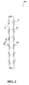
FIG. 2 is a plan view of a two way barbed suture having compound barbs formed in accordance with the present disclosure; -
FIG. 3 is a plan view of an alternative embodiment of a barbed suture having both single angle barbs and compound barbs formed in accordance with the present disclosure; -
FIG. 4A is a plan view of a segment of a barbed suture having compound barbs formed in accordance with the present disclosure; -
FIG. 4B is a plan view of an alternative embodiment of a segment of a barbed suture having compound barbs formed in accordance with the present disclosure; -
FIG. 5 is a plan view of a segment of a bi-directional barbed suture having compound barbs formed in accordance with the present disclosure; -
FIG. 6 is a plan view of an alternative embodiment of a barbed suture having compound barbs formed in accordance with the present disclosure; -
FIG. 7 is a plan view of an alternative embodiment of a barbed suture having compound barbs formed in accordance with the present disclosure; -
FIG. 8 is a plan view of a segment of a barbed suture having compound barbs and a loop formed at one end in accordance with the present disclosure; -
FIG. 9 is a schematic view of an embodiment of an apparatus and method of forming barbs on a medical device in accordance with the present disclosure. -
FIG. 10 is a plan view of an alternate embodiment of a segment of a barbed device having compound barbs formed in accordance with the present disclosure; and -
FIG. 11 is a plan view of another embodiment of a segment of a barbed device having compound barbs formed in accordance with the present disclosure. - Referring in detail to the drawings in which like reference numerals are applied to like elements in the various views,
FIG. 1 illustrates amedical device 100 having anelongated body 14 and at least onecompound barb 12 extending from theelongated body 14.Compound barb 12 defines an inner surface which includes afirst portion 12a disposed at a first orientation relative to the longitudinal axis ofelongated body 14, asecond portion 12b disposed at a second orientation relative to the longitudinal axis, and athird portion 12c disposed at a third orientation relative to the longitudinal axis. -
Compound barbs 12 include at least one substantially linear portion. As illustrated inFIG. 1 , first, second andthird portions 12a-c are substantially linear. It is envisioned that at least one of the portions may be substantially non-linear, such as for example, arcuate as described hereinbelow. - As shown in the exemplary embodiment of
FIG. 1 ,compound barbs 12 may be formed projecting from themedical device 100 towards at least one end. In other alternative embodiments, multiple compound barbs may be formed such that some of the barbs project toward one end and the remaining barbs project toward the other end so as to form a bi-directionalmedical device 200 as generally illustrated inFIG. 2 . Alternatively, a plurality of axially spaced barbs may be formed in the same or random configuration and at different angles in relation to each other. Optionally, the medical device may include a plurality of barbs spaced at the same or different lengths according to the type of tissue being manipulated and/or procedure performed (not shown). In some embodiments, the compound barb medical device incorporates a loop at the proximal end thereof configured to enhance retention of the device in body tissue at a desired position. - In an alternative embodiment,
medical device 300 may be formed to include a combination ofcompound barbs 12 andsingle angle barbs 13 as shown inFIG. 3 . In such an embodiment, thecompound barbs 12 andsingle angle barbs 13 may be formed along the length of themedical device 300 in specified or random patterns. Additionally, themedical device 300 may be formed such thatcompound barbs 12 are all oriented in the same direction toward one end ofmedical device 300 and thesingle angle barbs 13 are all oriented in the same direction toward the other end ofmedical device 300. - Referring to
FIG. 4A ,compound barbs 12 having first, second andthird portions 12a-c are generally formed by cutting into the surface ofelongated body 14. In embodiments, each of the first, second, andthird portions 12a-c may be cut at first, second and third angles α, β, and γ relative to longitudinal axes a, b, and c respectively ofelongated body 14 which are parallel to a central longitudinal axis 'D-D', wherein the second angle β is less than the first angle α, and the third angle γ is less than the second angle β.Compound barb 12 may include afirst portion 12a which is formed by cutting intoelongated body 14 at a first angle α of from about 0 degrees to about 90 degrees relative to longitudinal axis "a", in other embodiments, the first angle α ranges from about 30 degrees to about 50 degrees relative to longitudinal axis "a", asecond portion 12b which is formed by cutting intoelongated body 14 at a second angle β of from about 0 degrees to about 90 degrees relative to the longitudinal axis "b", in other embodiments, the second angle β ranges from about 2 degrees to about 25 degrees relative to the longitudinal axis "b", and athird portion 12c which is formed by cutting intoelongated body 14 at a third angle γ of from about 0 degrees to about 90 degrees relative to longitudinal axis "c", in other embodiments, the third angle γ ranges from about 2 degrees to about 50 degrees relative to longitudinal axis "c". - In other embodiments, a compound barb medical device includes an elongated body which includes first and second portions, the first and second portions of the elongated body are at first and second angles respective to a longitudinal axis of the elongated body to form at least one compound barb (not shown). Optionally, the elongated body of the compound barb medical device may include a third portion at a third angle respective to a longitudinal axis of the elongated body.
- Referring to
FIG. 4B , each of the first, second andthird portions 12a-c' may be cut at first, second and third angles α', β', and γ' relative to the longitudinal axes "a"', "b"', and "c"', respectively, ofelongated body 140, such that angle α' is greater than angle β' and angle γ' is less than angle β'.Compound barb 120 may include afirst portion 120a which is formed by cutting intoelongated body 140 at a first angle α' of from about 0 degrees to about 90 degrees relative to longitudinal axis "a"', in other embodiments, the first angle α' ranges from about 30 degrees to about 50 degrees relative to longitudinal axis "a'", asecond portion 120b which is formed by cutting intoelongated body 140 at a second angle β' of from about 0 degrees to about 90 degrees relative to longitudinal axis "b"', in other embodiments, a second angle β' ranges from about 30 degrees to about 60 degrees relative to longitudinal axis "b"', and athird portion 12c which is formed by cutting intoelongated body 140 at a third angle γ' of from about 0 degrees to about 90 degrees relative to longitudinal axis "c"', in other embodiments, a third angle γ' ranges from about 25 degrees to about 50 degrees relative to longitudinal axis "c"'. - An alternate embodiment of a compound barb suture is shown in
FIG. 10 . Thecompound barb 620 includes two portions 620a, 620b which are disposed at two angles, α" and β" relative to a longitudinal axis A-A of the medical device. More specifically, thecompound barb 620 includes a first portion 620a formed from theelongate body 610 at a first angle α",which is from about 0 degrees to about 90 degrees, in certain embodiments, from about 30 degrees to about 40 degrees, and in further embodiments, from about 31 degrees to about 38 degrees, relative to the longitudinal axis A-A of theelongate body 610. The second portion 620b is formed from theelongate body 610 at a second angle β" which is from about 0 degrees to about 90 degrees, in embodiments, from about 1 degrees to about 10 degrees and in further embodiments, from about 1 degree to about 8 degrees relative to the longitudinal axis A-A of theelongate body 610. - Another embodiment of a compound barb device is shown in
FIG. 11 . An elongate body 700 is shown including acompound barb 720 having a first linear portion 720a, shown at an angle γ", relative to a longitudinal axis B-B of the elongate body 700. Extending from the first portion 720a is an arcuate second portion 720b at a radius r7. The elongate body 700 also includes a compound barb wherein a first portion 740a is arcuate and a second portion 740b is linear. -
FIG. 5 illustratescompound barb 12 having threeportions 12a-c, as illustrated inFIGS. 4A and5 , andcompound barb 120 having threeportions 120a-c as illustrated inFIGS. 4B and5 , formed such that some of the barbs project toward one end and the remaining barbs project toward the other end so as to form a bi-directional medical device 500. In alternative embodiments, compound barbs are formed such that the barbs projecting toward one end, for example, towards the proximal end, have the same orientation and angles as the barbs projecting towards the other end, for example, towards the distal end. - In some embodiments, the compound barb may include at least one portion which is substantially non-linear. In embodiments, the barbs may include at least one point of inflection which may define a concave portion, a convex portion, an arcuate portion and combinations thereof. For example, at least one of the portions may be cut at a radius relative to the longitudinal axis of
elongated body 240. As shown inFIG. 6 ,compound barb 220 may include an arcuate second portion 220b. The arcuate portion 220b may be cut at a radius r1 relative to the longitudinal axis ofelongated body 240. - In alternative embodiments, an optional fourth portion may be cut at a fourth radius. In some embodiments, each of the first, second, third and optional
fourth portions 320a-d may be cut at first, second, third and fourth radii relative to the longitudinal axis ofelongated body 340. As illustrated inFIG. 7 ,compound barb 320 may include an arcuatefirst portion 320a which extends away fromelongated body 340 at a first radius r2, an arcuatesecond portion 320b which extends fromfirst portion 320a at a second radius r3, an arcuatethird portion 320c which extends fromsecond portion 320b at a third radius r4, an arcuatefourth portion 320d which extends fromthird portion 320c at a fourth radius r5. - In other embodiments, a compound barb medical device may include an elongated body having a barb and first, second, and third portions being cut at first, second, and third angles respective to a longitudinal axis of the elongated body to form the barb.
- The medical device in accordance with the present disclosure may be formed of the type selected from the group consisting of monofilament sutures, braided sutures, multi-filament sutures, surgical fibers, anchors, slit sheets, ribbons, tape, mesh, stent, scaffolds, pledgets, vascular graft and ribbons. In an exemplary embodiment, the medical device is a suture.
- The exemplary medical devices illustrated throughout the figures are shown to be elliptical in cross-sectional geometry. However, the cross-sectional geometry of the medical device may be of any suitable shape, for example, round, square, star shaped, octagonal, rectangular, polygonal and flat.
- In some embodiments, a loop is formed at the proximal end of the compound barb medical device which is configured to enhance retention of the device in body tissue at a desired position. As illustrated in
FIG. 8 ,loop 410 is formed at the proximal end of the compound barb medical device 400.Loop 410 may be fixed at a predetermined location along the length of theelongated body 440 of the compound barb medical device 400.Loop 410 may be configured and dimensioned to be adjustable along the length of elongated body 440 (not shown). - In general, a method for forming a compound barb on a medical device includes the steps of providing a medical device having a longitudinal axis and forming a compound barb along the medical device wherein the compound barb defines an inner surface which includes at least a first portion disposed at a first orientation relative to the longitudinal axis, a second portion disposed at a second orientation relative to the longitudinal axis, and a third portion disposed at a third orientation relative to the longitudinal axis. In embodiments, at least one of the first, second, and third portions is substantially linear. In alternative embodiments, at least one of the first, second, and third portions is substantially non-linear or arcuate.
- In embodiments, a method of forming a compound barb on a medical device includes forming a first cut in the medical device, the first cut having a first ratio of cut depth to diameter of the medical device; forming a second cut in the medical device, the second cut having a second ratio of cut depth to diameter of the medical device; and forming a third cut in the medical device, the third cut having a third ratio of cut depth to diameter of the medical device.
-
Fig. 9 illustrates an embodiment of an apparatus and method of forming compound barbs in accordance with the present disclosure. The method is described, for example inU.S. Patent Application No. 60/994,173 filed September 17, 2007 apparatus 60 that includes aconverter 62 which transmits ultrasonic energy to ahorn 66 that is operatively coupled toconverter 62.Converter 62 converts electrical energy to mechanical energy which causes displacement of the tool at an ultrasonic frequency powered by an ultrasonic generator orbooster 68.Booster 68 may be manipulated to either increase or decrease the ultrasonic frequency which may be transmitted to the tool. The ultrasonic frequency may range from about 1 kHz to about 100 kHz. In other embodiments, the ultrasonic frequency may range from about 10 kHz to about 90 kHz. In still further embodiments, the ultrasonic frequency may range from about 15 kHz to about 50 kHz. The ultrasonic signal amplitude may range from about 1 µ to about 125 µ. In other embodiments, the signal amplitude may range from about 15 µ to about 60 µ. - The ratio of the cut depth and the angle of the barbs relative to the elongated body of the medical device are variable based on the signal amplitude of ultrasonic energy applied to the cutting element. For example, as the ultrasonic amplitude is increased, the ratio of the cut depth to the diameter and the angle of the barbs are decreased. As the ultrasonic amplitude is decreased, the ratio of the cut is increased.
- Referring back to
FIG. 4A , in some embodiments, thecompound barbs 12 as formed have a first angle α of approximately 0 degrees to about 90 degrees, in embodiments, from 30 degrees to 50 degrees betweencompound barb 12 andelongated body 14 and a first ratio of cut depth which is approximately 1% to about 40%, and in certain embodiments, about 10% to about 30% of the diameter of the body. -
Compound barb 12 as formed by the method of the present disclosure may have a second angle β of approximately 0 degrees to about 90 degrees, in embodiments, from 5 degrees to 40 degrees relative to the longitudinal axis with a second ratio of cut depth of approximately 5% to about 50%, and in certain embodiments, about 15% to about 45% of the diameter ofelongated body 14.Compound barb 12 as formed by the method of the present disclosure may have a third angle γ of approximately 0 degrees to about 90 degrees, in embodiments, from about 25 degrees to about 50 degrees relative to the longitudinal axis with a third ratio of cut depth of approximately 15% to about 50%, and in some embodiments, from about 30% to about 50% the diameter ofelongated body 14. In one embodiment, a plurality of barbs are formed at successive intervals along the longitudinal axis of the medical device. - With continued reference to
FIG. 9 , theapparatus 60 optionally includes a gripper such asanvil 70 for supporting a medical device. Thegripper 70 supports the medical device at a fixed position. Thehorn 66 is configured and dimensioned to accept a cutting element such as a knife blade or a rotary blade (not shown) for forming the barbs on the medical device. Themotorized slide 74 moves in an X, Y, and Z plane to allow the medical device to pass in front of the converter to form barbs thereon.Apparatus 60 also includesrotational motor 76 which rotates the medical device in a circular direction.Advance slide 78 moves the medical device after every cut a specified increment for the appropriate barb spacing.Apparatus 60 optionally includescamera 72 for recording the method of forming barbs and alight source 74 for optimizing the view ofcamera 72. - In embodiments, the medical device is moved to be contact with the cutting element, or in other embodiments, the medical device is moved against the cutting element, at a specified first angle relative to the longitudinal axis of the elongated body of the medical device and forming a first ratio of cut depth to the diameter of approximately 1% to about 40%, in other embodiments more particularly a first ratio of cut depth to the diameter of approximately 10% to about 30%. While the cutting element is still in contact with the medical device, a second angle is cut having a ratio of cut depth to diameter of approximately 5% to about 50%, in other embodiments more particularly a ratio of cut depth to diameter of approximately 15% to about 45%. Optionally, in other embodiments, while the cutting element is still in contact with the medical device, a third angle is cut having a ratio of cut depth to diameter of approximately 15% to about 50%, in other embodiments more particularly a ratio of cut depth to diameter of approximately 30% to about 50%. The amount of time the blade is in contact with the medical device ranges, in embodiments, from about 1 millisecond to about 5 seconds. In other embodiments, the amount of time the blade is in contact with the medical device ranges from about 1 second to about 3 seconds. In still further embodiments, the amount of time the blade is in contact with the medical device is about 2 seconds.
- In embodiments, the knife blade may be shaped substantially into a rectangle shape, a square shape, a circle shape, a flat shape, an octagonal shape, a triangle shape, a star shape, a spade shape, an arrow shape, a key shape and an elliptical shape. In some embodiments, the curvature of the knife blade is substantially concave or substantially convex.
- In practice, the medical device passes in front of the
converter 62 which includes thehorn 66 and theanvil 70, then using ultrasonic energy at various frequencies and signal amplitudes cut the material to a geometry. In embodiments, the medical device passes in front ofconverter 62 viamotorized slide 74 which is configured and dimensioned to holdgripper 70 andcamera 72 thereon. In certain embodiments, the medical device passes in front ofconverter 62, via a mechanical feeding mechanism with the medical device held tightly around two spools on each side of the apparatus (not shown). In other embodiments, the medical device passes in front ofconverter 62 via human manipulation of the medical device. - Still referring to
FIG. 9 , theapparatus 60 includes aconverter 62 coupled to ahorn 66 which operatively moves along a straight line X-Y plane via ultrasonic vibrational energy. Thehorn 66 includes a blade which contacts a surface of the medical device at an angle so as to form at least one barb on the medical device. The blade is appropriately positioned to contact the medical device viaknife positioning slide 80. After each barb is formed, the medical device is moved in a linear motion on a X-Y plane via motorized slide 74 a specified length to allow another barb to be formed thereon. In embodiments, the medical device is moved in a X-Z plane via motorized slide 74 a specified length to form a barb thereon. In further embodiments, the medical device is moved in a Y-Z plane via motorized slide 74 a specified length to form a barb thereon. In alternative embodiments, the medical device is moved in a circular manner viarotational motor 76 to form a barb at a specified position. In embodiments, the medical device is moved in both a rotational and x-z plane rotation. - In practice, the
barbs 12 are formed as either the knife blade or rotary blade (not shown) contacts the outer surface of the medical device. The blade may be urged into contact with the surface of the medical device, for example, by a reciprocating actuator in a straight line X-Y plane. It is contemplated, however, that in alternative embodiments, the blade may be held fixed and the medical device may be urged toward the blade. The blade makes contact with the surface of the medical device at an angle relative thereto such that the combined action of the movement of the blade into contact with the medical device surface and the ultrasonic vibration of the knife forms the desired barb.Advance slide 78 then moves the medical device after every cut a specified increment for the desired spacing of the barbs. - Ultrasonic energy may transfer heat to the medical device as it is forming the barbs thereon. Depending on the amplitude, the ultrasonic frequency may cause melting of medical device if the blades are left to penetrate medical device throughout the full wave cycle. To prevent this from occurring, in some embodiments, the application of ultrasonic energy is discontinued at some point prior to withdrawal of the blades from contact of the medical device. In other embodiments, this method may be used to vary the angle and the depth of the cut as indicated above with respect to the increase or decrease of the amplitude.
- In some embodiments, barbs may be formed by making acute angular cuts directly into the medical device body, with cut portions pushed outwardly and separated from the body of the medical device. The depth of the barbs thus formed in the medical device body may depend on the diameter of the material and the depth of the cut.
- In some embodiments, a suitable device for cutting a plurality of axially spaced barbs on the exterior of a filament may use a gripper as a cutting bed, a cutting bed vise, a cutting template, and a converter and horn as the blade assembly to perform the cutting. In operation, the cutting device has the ability to produce a plurality of axially spaced barbs in the same or random configuration and at different angles in relation to each other.
- In other embodiments, the barbs may be arranged on a first portion of a length of the medical device body to allow movement of a first end of the medical device through tissue in one direction, while barbs on a second portion of the length of the medical device body may be arranged to allow movement of the second end of the medical device in an opposite direction.
- The barbs can be arranged in any suitable pattern, for example, helical, spiral, linear, or randomly spaced. The pattern may be symmetrical or asymmetrical. The number, configuration, spacing and surface area of the barbs can vary depending upon the tissue in which the medical device is used, as well as the composition and geometry of the material utilized to form the medical device. Additionally, the proportions of the barbs may remain relatively constant while the overall length of the barbs and the spacing of the barbs may be determined by the tissue being connected. For example, if the medical device is to be used to connect the edges of a wound in skin or tendon, the barbs may be made relatively short and more rigid to facilitate entry into this rather firm tissue. Alternatively, if the medical device is intended for use in fatty tissue, which is relatively soft, the barbs may be made longer and spaced further apart to increase the ability of the suture to grip the soft tissue.
- The surface area of the barbs can also vary. For example, fuller-tipped barbs can be made of varying sizes designed for specific surgical applications. For joining fat and relatively soft tissues, larger barbs may be desired, whereas smaller barbs may be more suitable for collagen-dense tissues. In some embodiments, a combination of large and small barbs within the same structure may be beneficial, for example when a suture is used in tissue repair with differing layer structures. In particular embodiments, a single directional suture may have both large and small barbs; in other embodiments a bi-directional suture may have both large and small barbs.
- Medical devices in accordance with the present disclosure may be formed of absorbable materials, non-absorbable materials, and combinations thereof. More particularly, the medical device may be formed of an absorbable material selected from the group consisting of polyesters, polyorthoesters, polymer drugs, polydroxybutyrates, dioxanones, lactones, proteins, cat gut, collagens, carbonates, homopolymers thereof, copolymers thereof, and combinations thereof. In other embodiments, suitable absorbable materials which may be utilized to form the medical device include natural collagenous materials or synthetic resins including those derived from alkylene carbonates such as trimethylene carbonate, tetramethylene carbonate, and the like, caprolactone, glycolic acid, lactic acid, glycolide, lactide, homopolymers thereof, copolymers thereof, and combinations thereof. In some embodiments, glycolide and lactide based polyesters, especially copolymers of glycolide and lactide, may be utilized to form the medical device of the present disclosure.
- Barbed medical devices fabricated from an absorbable material in accordance with the present disclosure maintain their structural integrity after implantation (e.g., about 80% of original strength) for a period of time, depending on the various processing parameter and the particular copolymer used. Such characteristics include, for example, the components of the copolymer, including both the monomers utilized to form the copolymer and any additives thereto, as well as the processing conditions (e.g., rate of copolymerization reaction, temperature for reaction, pressure, etc.), and any further treatment of the resulting copolymers, i.e., coating, sterilization, etc.
- The formation of barbs on a suture body may be utilized to alter the degradation time of a suture in accordance with the present disclosure as described in
U.S. Patent Application No. 11/556,002 filed on November 2, 2006 - For non-absorbable barbed medical devices constructed in accordance with the present disclosure, suitable non-absorbable materials which may be utilized to form the medical device include polyolefins, such as polyethylene, polypropylene, copolymers of polyethylene and polypropylene, and blends of polyethylene and polypropylene; polyamides (such as nylon); polyamines, polyimines, polyesters such as polyethylene terephthalate; fluoropolymers such as polytetrafluoroethylene; polyether-esters such as polybutesters; polytetramethylene ether glycol; 1,4-butanediol; polyurethanes; and combinations thereof. In other embodiments, non-absorbable materials may include silk, cotton, linen, carbon fibers, and the like. The polypropylene can be isotactic polypropylene or a mixture of isotactic and syndiotactic or atactic polypropylene.
- The filaments and fibers used for forming the medical device of the present disclosure may be formed using any technique within the purview of those skilled in the art, such as, for example, extrusion, molding and/or solvent casting.
- In one preferred embodiment, compound barbs are formed on a monofilament suture. A barbed monofilament suture may be preferred in embodiments where higher strength and longer absorption and strength profiles are preferred. The compound barb monofilament sutures may be preferred, for example, in dermal application where there is an increased risk of infection.
- In some embodiments, devices of the present disclosure may include a yarn made of more than one filament, which may contain multiple filaments of the same or different materials. Where the devices are made of multiple filaments, the device can be made using any known technique such as, for example, braiding, weaving or knitting. The filaments may also be combined to produce a non-woven suture. The filaments themselves may be drawn, oriented, crinkled, twisted, commingled or air entangled to form yarns as part of the suture forming process.
- In other embodiments, compound barb medical devices may include other medical devices such as braided sutures, surgical fibers, anchors, slit sheets, ribbons, tapes, meshes, stents, scaffolds, pledgets, and vascular grafts.
- Once the medical device is barbed, it can be sterilized by any means within the purview of those skilled in the art.
- Medical devices in accordance with the present disclosure may be coated or impregnated with one or more synthetic or natural polymers e.g., bioactive agents which accelerate or beneficially modify the healing process when the suture is applied to a wound or surgical site. In certain embodiments, the coating may be formed from absorbable polymers selected from the group consisting of lactones, carbonates, polyorthoesters, hydroxyalkoanates, hydroxybutyrates, bioactive agents, polyanhydrides, silicone, vinyl polymers, high molecular weight waxes and oils, natural polymers, proteins, polysaccharides, suspendable particulates, dispersible particulates, microspheres, nanospheres, rods, homopolymers thereof, copolymers thereof, and combinations thereof.
- Suitable bioactive agents include, for example, biocidal agents, antimicrobial agents, antibiotics, anti-proliferatives, medicants, growth factors, anti-clotting agents, clotting agents, analgesics, anesthetics, anti-inflammatory agents, wound repair agents and the like, chemotherapeutics, biologics, protein therapeutics, monoclonal or polyclonal antibodies, DNA, RNA, peptides, polysaccharides, lectins, lipids, probiotics, diagnostic agents, angiogenics, anti-angiogenic drugs, polymeric drugs, and combinations thereof.
- Bioactive agents include substances which are beneficial to the animal and tend to promote the healing process. For example, a suture can be provided with a bioactive agent that will be deposited at the sutured site. The bioactive agent can be chosen for its antimicrobial properties, capability for promoting wound repair and/or tissue growth, or for specific indications such as thrombosis. In embodiments, combinations of such agents may be applied to the medical device of the present disclosure after formation of the barbs.
- The term "antimicrobial agent" as used herein includes an agent which by itself or through assisting the immune system, helps the body destroy or resist microorganisms which may be pathogenic. An antimicrobial agent includes antibiotics, antiseptics, quorum sensing blockers, antifungals, anti-virals, surfactants, metal ions, antimicrobial proteins and peptides, antimicrobial polysaccharides, disinfectants and combinations thereof. Antimicrobial agents which are slowly released into the tissue can be applied in this manner to aid in combating clinical and sub-clinical infections in a surgical or trauma wound site. In embodiments, suitable antimicrobial agents may be soluble in one or more solvents.
- In embodiments, the following anti-microbial agents may be used alone or in combination with other bioactive agents described herein: an anthracycline, doxorubicin, mitoxantrone, a fluoropyrimidine, 5-fluorouracil (5-FU), a folic acid antagonist, methotrexate, mitoxantrone, quorum sensing blocker, brominated or halogenated furanones, a podophylotoxin, etoposide, camptothecin, a hydroxyurea, a platinum complex, cisplatin, doxycycline, metronidazole, trimethoprim-sulfamethoxazole, rifamycins like rifampin, a fourth generation penicillin (e.g., a ureidopenicillin a carboxypenicillin, meziocillin, piperacillin, carbenicillin, and ticarcillin, and an analogue or derivative thereof), a first generation cephalosporin (e.g., cephazolin sodium, cephalexin, cefazolin, cephapirin, and cephalothin), a carboxypenicillin (e.g., ticarcillin), a second generation cephalosporin (e.g., cefuroxime, cefotetan, and cefoxitin), a third generation cephalosporin (e.g., naxcel, cefdinir, cefoperazone, ceftazidime, ceftriaxone, and cefotaxime), polyvinyl pyrrolidone (PVP), a fourth generation cephalosporin (e.g., cefepime), a monobactam (e.g., aztreonam), a carbapenem (e.g., imipenem, ertapenem and meropenem), an aminoglycoside (e.g., streptomycin, gentamicin, tobramycin, and amikacin), an MSL group member (e.g., a macrolide, a long acting macrolide, a lincosamide, a streptogramin, Erythromycin, Azithromycin, Clindamycin, Syneroid, clarithromycin, and kanamycin sulfate), tetracyclines like minocycline, fusidic acid, trimethoprim, metronidazole; a quinolone (e.g., ciprofloxacin, ofloxacin, gatifloxacin, moxifloxacin, levofloxacin, and trovafloxacin), a DNA synthesis inhibitor (e.g., metronidazole), a sulfonamide (e.g. sulfamethoxazole, trimethoprim, including cefixime, spectinomycin, tetracycline, nitrofurantoin, polymyxin B, and neomycin sulfate), beta-lactam inhibitors like sulbactam, chloramphenicol, glycopeptides like vancomycin, mupirocin, polyenes like amphotericin B, azoles like fluconazole, and other known antimicrobial agent known in the art.
- Examples of chemotherapeutics which may be utilized include one or more of the following: doxorubicin (Dox), paclitaxel (PTX), or camptothecin (CPT), polyglutamate-PTX (CT-2103 or Xyotax), N-(2-hydroxypropyl)methacrylamide (HPMA) copolymer, anthracycline, mitoxantrone, letrozole, anastrozole, epidermal growth factor receptor inhibitors, tyrosine kinase inhibitors,modulators of apoptosis, anthracycline antibiotics such as daunorubicin and doxorubicin, alkylating agents such as cyclophosphamide and melphalan, antimetabolites such as methotrexate and 5-fluorouracil, poly(ethylene glycol) (PEG), poly(glutamic acid) (PGA), polysaccharides, monoclonal antibody and polymer-drug conjugates thereof, copolymers thereof and combinations thereof.
- The clotting agents include one or more of the following: a fibrosing agent that promotes cell regeneration, a fibrosing agent that promotes angiogenesis, a fibrosing agent that promotes fibroblast migration, a fibrosing agent that promotes fibroblast proliferation, a fibrosing agent that promotes deposition of extracellular matrix, a fibrosing agent that promotes tissue remodeling, a fibrosing agent that is a diverticular wall irritant, silk (such as silkworm silk, spider silk, recombinant silk, raw silk, hydrolyzed silk, acid-treated silk, and acylated silk), talc, chitosan, bleomycin or an analogue or derivative thereof, connective tissue growth factor (CTGF), metallic beryllium or an oxide thereof, copper, saracin, silica, crystalline silicates, quartz dust, talcum powder, ethanol, a component of extracellular matrix, oxidized cellulose, polysaccharides, collagen, fibrin, fibrinogen, poly(ethylene terephthalate), poly(ethylene-co-vinylacetate), N-carboxybutylchitosan, an RGD protein, a polymer of vinyl chloride, cyanoacrylate, crosslinked poly(ethylene glycol)-methylated collagen, an inflammatory cytokine, TGFβ, PDGF, VEGF, TNFα, NGF, GM-CSF, IGF-α, IL-1, IL-8, IL-6, a growth hormone, a bone morphogenic protein, a cell proliferative agent, dexamethasone, isotretinoin, 17-β-estradiol, estradiol, diethylstibesterol, cyclosporine a, all-trans retinoic acid or an analogue or derivative thereof, wool (including animal wool, wood wool, and mineral wool), cotton, bFGF, polyurethane, polytetrafluoroethylene, activin, angiopoietin, insulin-like growth factor (IGF), hepatocyte growth factor (HGF), a colony-stimulating factor (CSF), erythropoietin, an interferon, endothelin-1, angiotensin II, bromocriptine, methylsergide, fibrosin, fibrin, an adhesive glycoprotein, proteoglycan, hyaluronan, secreted protein acidic and rich in cysteine (SPaRC), a thrombospondin, tenacin, a cell adhesion molecule, dextran based particles, an inhibitor of matrix metalloproteinase, magainin, tissue or kidney plasminogen activator, a tissue inhibitor of matrix metalloproteinase, carbon tetrachloride, thioacetamide, superoxide dismutase to scavenge tissue-damaging free radicals, tumor necrosis factor for cancer therapy, colony stimulating factor, interferon, interleukin-2 or other lymphokines to enhance the immune system, platelet rich plasma, thrombin, peptides such as self assembly peptide systems, amino acids such as radA based amino acids, hydrogels such as super absorbing hydrogel materials, combinations thereof, and so forth.
- A wide variety of anti-angiogenic factors may be readily utilized within the context of the present disclosure. Representative examples include Anti-Invasive Factor; retinoic acid and derivatives thereof; paclitaxel a highly derivatized diterpenoid; Suramin; Tissue Inhibitor of Metalloproteinase-1; Tissue Inhibitor of Metalloproteinase-2; Plasminogen Activator Inhibitor-1; Plasminogen Activator Inhibitor-2; various forms of the lighter "d group" transition metals such as, for example, vanadium, molybdenum, tungsten, titanium, niobium, and tantalum species and complexes thereof; Platelet Factor 4; Protamine Sulphate (Clupeine); Sulphated Chitin Derivatives (prepared from queen crab shells); Sulphated Polysaccharide Peptidoglycan Complex (SP-PG) (the function of this compound may be enhanced by the presence of steroids such as estrogen, and tamoxifen citrate); Staurosporine; Modulators of Matrix Metabolism, including for example, proline analogs {[(L-azetidine-2-carboxylic acid (LACA), cishydroxyproline, d,L-3,4-dehydroproline, Thiaproline, α,α-dipyridyl, β-aminopropionitrile fumarate; MDL 27032 (4-propyl-5-(4-pyridinyl)-2(3H)-oxazolone; Methotrexate; Mitoxantrone; Heparin; Interferons; 2 Macroglobulin-serum; ChIMP-3; Chymostatin; β-Cyclodextrin Tetradecasulfate; Eponemycin; Camptothecin; Fumagillin Gold Sodium Thiomalate ("GST"); D-Penicillamine ("CDPT'); β-1-anticollagenase-serum; α2-antiplasmin; Bisantrene; Lobenzarit disodium (N-(2)-carboxyphenyl-4-chloroanthronilic acid disodium or "CCA"; Thalidomide; Angostatic steroid; AGM-1470; carboxynaminolmidazole; metalloproteinase inhibitors such as BB94, analogues and derivatives thereof, and combinations thereof.
- A wide variety of polymeric drugs may be readily utilized within the context of the present disclosure. Representative examples include steroidal anti-inflammatory agents, non-steroidal anti-inflammatory agents, and combinations thereof. Examples of the non-steroidal anti-inflammatory agent which may be used with the present disclosure are aspirin, indomethacin, ibuprofen, phenylbutazone, diflusinal, and combinations thereof.
- Examples of the steroidal anti-inflammatory agent which may be used are glucocorticoids such as cortisone and hydrocortisone, betamethasone, dexamethasone, fluprednisolone, prednisone, methylprednisolone, prednisolone, triamcinolone, paramethasone, and combinations thereof.
- Although the above bioactive agents have been provided for the purposes of illustration, it should be understood that the present disclosure is not so limited. In particular, although certain bioactive agents are specifically referred to above, the present disclosure should be understood to include analogues, derivatives and conjugates of such agents.
- Medical devices in accordance with this disclosure can also include, for example, biologically acceptable plasticizers, antioxidants and colorants, which can be impregnated into the filament(s) utilized to form a suture of the present disclosure or included in a coating thereon.
- Bioactive agents may be applied onto a barbed medical device of the present disclosure utilizing any method within the purview of one skilled in the art including, for example, dipping, spraying, vapor deposition, brushing, mixing, compounding and the like. In embodiments, a bioactive agent may be deposited within the barb angles, that is, the angle formed between the barb and the medical device surface in accordance with the present disclosure as described in
U.S. Patent Application No. 11/899,852 filed on September 6, 2007 - Medical devices of the present disclosure may contain additives such as dyes, pigments, and colorants in order to increase the visibility of the device in the surgical field. Any suitable agent such as those agents within the purview of those skilled in the art can be used in accordance with the present disclosure.
- The filaments and sutures of the present disclosure may additionally include a needle at one end. In order to facilitate needle attachment to a suture of the present disclosure, conventional tipping agents can be applied to the braid. Two tipped ends of the suture may be desirable for attaching a needle to each end of the suture to provide a so-called double armed suture. The needle attachment can be made by any conventional method such as crimping, swaging, and the like.
- In some cases, a tubular insertion device (not shown) may be utilized to introduce a barbed medical device in accordance with the present disclosure into tissue. Such a tubular insertion device may have a tubular body in which the barbed medical device of the present disclosure is disposed, as well as a distal end and a proximal end. In use, in some embodiments, the pointed end of a barbed suture of the present disclosure may be pushed with the distal end of the tubular insertion device through skin, tissue, and the like at an insertion point. The pointed end of the suture and the distal end of the tubular insertion device are pushed through the tissue until reaching an endpoint. The proximal end of the tubular insertion device is then gripped and pulled to remove the insertion device, leaving the barbed suture in place.
- Barbed sutures and placement methods suitable for use according to the present disclosure are well known in the art. For example, in embodiments, medical devices of the present disclosure may be utilized to provide lift to tissue, which may be desirable in certain cosmetic applications. In some embodiments, a procedure for closing tissue utilizing barbed sutures includes inserting a first end of a monofilament suture, optionally attached to a needle, at an insertion point through the body tissue. The first end of the suture may be pushed through body tissue until the first end extends out of the body tissue at an exit point. The first end of the monofilament suture may then be gripped and pulled to draw the first portion of the suture through the body tissue so that an outer surface of the elongate body (of the first portion) of the suture remains in direct contact with the body tissue between the point of insertion and exit point of the first end. As shown, for example in
Figure 10 , the outer surface 630 of theelongate body 610 is in direct contact with tissue "T." The outer surface 630 may be in direct contact with tissue "T" for any length "L" of the elongate body and is not limited to the contact length "L" shown inFigure 10 . The body tissue may then be manually grouped and advanced along at least one portion of the monofilament suture to provide the desired amount of lift. - The medical devices of the present disclosure may be utilized in any cosmetic, endoscopic or laparoscopic methods. In addition, sutures of the present disclosure may be utilized to attach one tissue to another including, but not limited to, attaching tissue to a ligament. Specific applications of cosmetic surgeries include, for example, facelifts, browlifts, thigh lifts, and breast lifts.
- While the above description contains many specifics, these specifics should not be construed as limitations on the scope of the disclosure, but merely as exemplifications of embodiments thereof. Those skilled in the art will envision many other possibilities within the scope and spirit of the disclosure as defined by the claims appended hereto.
Claims (15)
- A compound barb medical device comprising:an elongated body;at least one barb extending from the elongated body and defining an inner surface, the inner surface including:a first portion disposed at a first orientation relative to a longitudinal axis of the elongated body,a second portion disposed at a second orientation relative to the longitudinal axis, anda third portion disposed at a third orientation relative to the longitudinal axis.
- A compound barb medical device comprising:an elongate body wherein the elongate body is a monofilament suture including an outer surface, and the outer surface is in direct contact with tissue;at least one barb extending from the elongated body and defining an inner surface, the inner surface including:a first portion disposed at a first orientation relative to a first longitudinal axis of the elongate body, wherein the first portion is disposed at a first angle from about 0 degrees to about 90 degrees relative to the first longitudinal axis of the elongate body; anda second portion disposed at a second orientation relative to a second longitudinal axis of the elongate body, wherein the second portion is disposed at a second angle from about 0 degrees to about 90 degrees relative to the second longitudinal axis of the elongate body.
- The compound barb medical device according to claim 2, wherein the first angle is from about 30 degrees to about 40 degrees; or wherein the second angle is from about 1 degree to about 10 degrees.
- The compound barb medical device according to claims 1 or 2, wherein at least one of the first, second, and third portions is substantially linear.
- The compound barb medical device according to any of the preceding claims, wherein the first, second, and third portions are at first, second, and third angles relative to respective longitudinal axes of the elongated body; or wherein at least one of the first, second, and third portions is substantially non-linear; or wherein at least one of the first, second, and third portions is substantially linear.
- The compound barb medical device according to claim 1, wherein the first, second and third, angle is about 0 degrees to about 90 degrees.
- The compound barb medical device according to any of the preceding claims, wherein the medical device is formed of the type selected from the group consisting of monofilament sutures, multifilament sutures, surgical fibers, anchors, slit sheets, ribbons, tapes, meshes, stents, scaffolds, pledgets, and vascular grafts.
- The compound barb medical device according to claim 7, wherein a proximal end of the suture comprises a loop.
- A compound barb medical device which comprises an elongated body including a plurality of barbs formed along at least a portion of a length thereof wherein at least one of the plurality of barbs has an inner surface having at least one inflection point.
- The compound barb medical device according to any of the preceding claims, wherein at least one of the first and second and third portions is arcuate.
- A method of forming a compound barb on a medical device, comprising the steps of:providing a medical device having a longitudinal axis;applying vibrational energy to a cutting element to form a compound barb on at least a portion of the medical device including:forming a first cut in the medical device, the first cut having a first ratio of cut depth to diameter of the medical device; andforming a second cut in the medical device, the second cut having a second ratio of cut depth to diameter of the medical device.
- The method according to claim 11, further comprising the step of forming a third cut in the medical device, the third cut having a third ratio of cut depth to diameter of the medical device.
- The method according to claim 11, wherein the first ratio is approximately 1% to about 40%; or wherein the second ratio is approximately 5% to about 50%; or wherein the third ratio is approximately 15% to about 50%.
- A medical device having compound barbs formed by claim 11.
- The medical device formed by claim 11, wherein the medical device is a suture and has a needle attached to at least one end.
Priority Applications (9)
| Application Number | Priority Date | Filing Date | Title |
|---|---|---|---|
| EP12151532.4A EP2449979B1 (en) | 2008-02-20 | 2009-02-20 | Compound barb medical device |
| EP12151535.7A EP2449980B1 (en) | 2008-02-20 | 2009-02-20 | Compound barb medical device and method of manufacturing |
| EP20120151537 EP2449981A1 (en) | 2008-02-20 | 2009-02-20 | Compound barb medical device and method |
| EP16159329.8A EP3053531B1 (en) | 2008-02-20 | 2009-02-20 | Compound barb medical device |
| EP20120151525 EP2449975A1 (en) | 2008-02-20 | 2009-02-20 | Compound barb medical device |
| EP20120151530 EP2449977A1 (en) | 2008-02-20 | 2009-02-20 | Compound barb medical device and method |
| EP10014285.0A EP2289428B1 (en) | 2008-02-20 | 2009-02-20 | Compound barb medical device and method |
| EP12151526.6A EP2449976B1 (en) | 2008-02-20 | 2009-02-20 | Compound barb medical device |
| EP20120151531 EP2449978A1 (en) | 2008-02-20 | 2009-02-20 | Compound barb medical device and method |
Applications Claiming Priority (2)
| Application Number | Priority Date | Filing Date | Title |
|---|---|---|---|
| US2996408P | 2008-02-20 | 2008-02-20 | |
| US12/361,962 US8273105B2 (en) | 2008-02-20 | 2009-01-29 | Compound barb medical device and method |
Related Child Applications (13)
| Application Number | Title | Priority Date | Filing Date |
|---|---|---|---|
| EP20120151531 Division-Into EP2449978A1 (en) | 2008-02-20 | 2009-02-20 | Compound barb medical device and method |
| EP16159329.8A Division EP3053531B1 (en) | 2008-02-20 | 2009-02-20 | Compound barb medical device |
| EP12151535.7A Division-Into EP2449980B1 (en) | 2008-02-20 | 2009-02-20 | Compound barb medical device and method of manufacturing |
| EP12151535.7A Division EP2449980B1 (en) | 2008-02-20 | 2009-02-20 | Compound barb medical device and method of manufacturing |
| EP12151532.4A Division-Into EP2449979B1 (en) | 2008-02-20 | 2009-02-20 | Compound barb medical device |
| EP12151532.4A Division EP2449979B1 (en) | 2008-02-20 | 2009-02-20 | Compound barb medical device |
| EP20120151530 Division-Into EP2449977A1 (en) | 2008-02-20 | 2009-02-20 | Compound barb medical device and method |
| EP12151526.6A Division EP2449976B1 (en) | 2008-02-20 | 2009-02-20 | Compound barb medical device |
| EP12151526.6A Division-Into EP2449976B1 (en) | 2008-02-20 | 2009-02-20 | Compound barb medical device |
| EP10014285.0A Division EP2289428B1 (en) | 2008-02-20 | 2009-02-20 | Compound barb medical device and method |
| EP10014285.0A Division-Into EP2289428B1 (en) | 2008-02-20 | 2009-02-20 | Compound barb medical device and method |
| EP20120151537 Division-Into EP2449981A1 (en) | 2008-02-20 | 2009-02-20 | Compound barb medical device and method |
| EP20120151525 Division-Into EP2449975A1 (en) | 2008-02-20 | 2009-02-20 | Compound barb medical device |
Publications (2)
| Publication Number | Publication Date |
|---|---|
| EP2092895A1 true EP2092895A1 (en) | 2009-08-26 |
| EP2092895B1 EP2092895B1 (en) | 2015-01-21 |
Family
ID=40668188
Family Applications (1)
| Application Number | Title | Priority Date | Filing Date |
|---|---|---|---|
| EP20090250460 Active EP2092895B1 (en) | 2008-02-20 | 2009-02-20 | Compound barb medical device and method |
Country Status (1)
| Country | Link |
|---|---|
| EP (1) | EP2092895B1 (en) |
Cited By (3)
| Publication number | Priority date | Publication date | Assignee | Title |
|---|---|---|---|---|
| WO2014167131A1 (en) | 2013-04-11 | 2014-10-16 | Cossa Jean-Pierre | Implantable reinforcement prosthesis, in particular for reinforcing the abdominal wall |
| CN108309374A (en) * | 2012-08-10 | 2018-07-24 | W.L.戈尔及同仁股份有限公司 | Devices, systems, and methods for engaging tissue |
| CN113440190A (en) * | 2021-06-28 | 2021-09-28 | 梁一凡 | Novel method for manufacturing knotting-free fishbone suture line |
Citations (6)
| Publication number | Priority date | Publication date | Assignee | Title |
|---|---|---|---|---|
| US20060116718A1 (en) * | 2003-08-07 | 2006-06-01 | Leiboff Arnold R | Device and method for tacking a prosthetic screen |
| US20070005110A1 (en) * | 2005-06-29 | 2007-01-04 | Collier John P | Braided barbed suture |
| US20070187861A1 (en) * | 2001-08-31 | 2007-08-16 | Quill Medical, Inc. | Method of Forming Barbs on a Suture and Apparatus for Performing Same |
| WO2007133103A1 (en) * | 2006-05-16 | 2007-11-22 | Marlen Andreevich Sulamanidze | Surgical suture material and a method to the use thereof |
| US20080058869A1 (en) | 2006-09-06 | 2008-03-06 | Stopek Joshua B | Bioactive substance in a barbed suture |
| US20080109036A1 (en) | 2006-11-02 | 2008-05-08 | Tyco Healthcare Group Lp | Long term bioabsorbable barbed sutures |
-
2009
- 2009-02-20 EP EP20090250460 patent/EP2092895B1/en active Active
Patent Citations (6)
| Publication number | Priority date | Publication date | Assignee | Title |
|---|---|---|---|---|
| US20070187861A1 (en) * | 2001-08-31 | 2007-08-16 | Quill Medical, Inc. | Method of Forming Barbs on a Suture and Apparatus for Performing Same |
| US20060116718A1 (en) * | 2003-08-07 | 2006-06-01 | Leiboff Arnold R | Device and method for tacking a prosthetic screen |
| US20070005110A1 (en) * | 2005-06-29 | 2007-01-04 | Collier John P | Braided barbed suture |
| WO2007133103A1 (en) * | 2006-05-16 | 2007-11-22 | Marlen Andreevich Sulamanidze | Surgical suture material and a method to the use thereof |
| US20080058869A1 (en) | 2006-09-06 | 2008-03-06 | Stopek Joshua B | Bioactive substance in a barbed suture |
| US20080109036A1 (en) | 2006-11-02 | 2008-05-08 | Tyco Healthcare Group Lp | Long term bioabsorbable barbed sutures |
Cited By (4)
| Publication number | Priority date | Publication date | Assignee | Title |
|---|---|---|---|---|
| CN108309374A (en) * | 2012-08-10 | 2018-07-24 | W.L.戈尔及同仁股份有限公司 | Devices, systems, and methods for engaging tissue |
| WO2014167131A1 (en) | 2013-04-11 | 2014-10-16 | Cossa Jean-Pierre | Implantable reinforcement prosthesis, in particular for reinforcing the abdominal wall |
| CN113440190A (en) * | 2021-06-28 | 2021-09-28 | 梁一凡 | Novel method for manufacturing knotting-free fishbone suture line |
| CN113440190B (en) * | 2021-06-28 | 2022-03-11 | 梁一凡 | Novel method for manufacturing knotting-free fishbone suture line |
Also Published As
| Publication number | Publication date |
|---|---|
| EP2092895B1 (en) | 2015-01-21 |
Similar Documents
| Publication | Publication Date | Title |
|---|---|---|
| US11660088B2 (en) | Compound barb medical device and method | |
| EP2481358B1 (en) | Method of forming barbs on a suture | |
| EP2092895B1 (en) | Compound barb medical device and method | |
| AU2015200379B2 (en) | Compound barb medical device and method |
Legal Events
| Date | Code | Title | Description |
|---|---|---|---|
| PUAI | Public reference made under article 153(3) epc to a published international application that has entered the european phase |
Free format text: ORIGINAL CODE: 0009012 |
|
| AK | Designated contracting states |
Kind code of ref document: A1 Designated state(s): AT BE BG CH CY CZ DE DK EE ES FI FR GB GR HR HU IE IS IT LI LT LU LV MC MK MT NL NO PL PT RO SE SI SK TR |
|
| AX | Request for extension of the european patent |
Extension state: AL BA RS |
|
| 17P | Request for examination filed |
Effective date: 20100113 |
|
| 17Q | First examination report despatched |
Effective date: 20100208 |
|
| AKX | Designation fees paid |
Designated state(s): AT BE BG CH CY CZ DE DK EE ES FI FR GB GR HR HU IE IS IT LI LT LU LV MC MK MT NL NO PL PT RO SE SI SK TR |
|
| RAP1 | Party data changed (applicant data changed or rights of an application transferred) |
Owner name: COVIDIEN LP |
|
| GRAP | Despatch of communication of intention to grant a patent |
Free format text: ORIGINAL CODE: EPIDOSNIGR1 |
|
| INTG | Intention to grant announced |
Effective date: 20140820 |
|
| GRAS | Grant fee paid |
Free format text: ORIGINAL CODE: EPIDOSNIGR3 |
|
| GRAA | (expected) grant |
Free format text: ORIGINAL CODE: 0009210 |
|
| AK | Designated contracting states |
Kind code of ref document: B1 Designated state(s): AT BE BG CH CY CZ DE DK EE ES FI FR GB GR HR HU IE IS IT LI LT LU LV MC MK MT NL NO PL PT RO SE SI SK TR |
|
| REG | Reference to a national code |
Ref country code: GB Ref legal event code: FG4D |
|
| REG | Reference to a national code |
Ref country code: CH Ref legal event code: EP |
|
| REG | Reference to a national code |
Ref country code: IE Ref legal event code: FG4D |
|
| REG | Reference to a national code |
Ref country code: DE Ref legal event code: R096 Ref document number: 602009029066 Country of ref document: DE Effective date: 20150305 |
|
| REG | Reference to a national code |
Ref country code: ES Ref legal event code: FG2A Ref document number: 2530890 Country of ref document: ES Kind code of ref document: T3 Effective date: 20150306 |
|
| REG | Reference to a national code |
Ref country code: AT Ref legal event code: REF Ref document number: 708796 Country of ref document: AT Kind code of ref document: T Effective date: 20150315 |
|
| REG | Reference to a national code |
Ref country code: NL Ref legal event code: VDEP Effective date: 20150121 |
|
| REG | Reference to a national code |
Ref country code: AT Ref legal event code: MK05 Ref document number: 708796 Country of ref document: AT Kind code of ref document: T Effective date: 20150121 |
|
| REG | Reference to a national code |
Ref country code: LT Ref legal event code: MG4D |
|
| PG25 | Lapsed in a contracting state [announced via postgrant information from national office to epo] |
Ref country code: BE Free format text: LAPSE BECAUSE OF NON-PAYMENT OF DUE FEES Effective date: 20150228 |
|
| PG25 | Lapsed in a contracting state [announced via postgrant information from national office to epo] |
Ref country code: HR Free format text: LAPSE BECAUSE OF FAILURE TO SUBMIT A TRANSLATION OF THE DESCRIPTION OR TO PAY THE FEE WITHIN THE PRESCRIBED TIME-LIMIT Effective date: 20150121 Ref country code: LT Free format text: LAPSE BECAUSE OF FAILURE TO SUBMIT A TRANSLATION OF THE DESCRIPTION OR TO PAY THE FEE WITHIN THE PRESCRIBED TIME-LIMIT Effective date: 20150121 Ref country code: BG Free format text: LAPSE BECAUSE OF FAILURE TO SUBMIT A TRANSLATION OF THE DESCRIPTION OR TO PAY THE FEE WITHIN THE PRESCRIBED TIME-LIMIT Effective date: 20150421 Ref country code: NO Free format text: LAPSE BECAUSE OF FAILURE TO SUBMIT A TRANSLATION OF THE DESCRIPTION OR TO PAY THE FEE WITHIN THE PRESCRIBED TIME-LIMIT Effective date: 20150421 Ref country code: SE Free format text: LAPSE BECAUSE OF FAILURE TO SUBMIT A TRANSLATION OF THE DESCRIPTION OR TO PAY THE FEE WITHIN THE PRESCRIBED TIME-LIMIT Effective date: 20150121 Ref country code: FI Free format text: LAPSE BECAUSE OF FAILURE TO SUBMIT A TRANSLATION OF THE DESCRIPTION OR TO PAY THE FEE WITHIN THE PRESCRIBED TIME-LIMIT Effective date: 20150121 |
|
| PG25 | Lapsed in a contracting state [announced via postgrant information from national office to epo] |
Ref country code: PL Free format text: LAPSE BECAUSE OF FAILURE TO SUBMIT A TRANSLATION OF THE DESCRIPTION OR TO PAY THE FEE WITHIN THE PRESCRIBED TIME-LIMIT Effective date: 20150121 Ref country code: IS Free format text: LAPSE BECAUSE OF FAILURE TO SUBMIT A TRANSLATION OF THE DESCRIPTION OR TO PAY THE FEE WITHIN THE PRESCRIBED TIME-LIMIT Effective date: 20150521 Ref country code: LV Free format text: LAPSE BECAUSE OF FAILURE TO SUBMIT A TRANSLATION OF THE DESCRIPTION OR TO PAY THE FEE WITHIN THE PRESCRIBED TIME-LIMIT Effective date: 20150121 Ref country code: AT Free format text: LAPSE BECAUSE OF FAILURE TO SUBMIT A TRANSLATION OF THE DESCRIPTION OR TO PAY THE FEE WITHIN THE PRESCRIBED TIME-LIMIT Effective date: 20150121 Ref country code: GR Free format text: LAPSE BECAUSE OF FAILURE TO SUBMIT A TRANSLATION OF THE DESCRIPTION OR TO PAY THE FEE WITHIN THE PRESCRIBED TIME-LIMIT Effective date: 20150422 Ref country code: NL Free format text: LAPSE BECAUSE OF FAILURE TO SUBMIT A TRANSLATION OF THE DESCRIPTION OR TO PAY THE FEE WITHIN THE PRESCRIBED TIME-LIMIT Effective date: 20150121 |
|
| REG | Reference to a national code |
Ref country code: CH Ref legal event code: PL |
|
| REG | Reference to a national code |
Ref country code: DE Ref legal event code: R097 Ref document number: 602009029066 Country of ref document: DE |
|
| PG25 | Lapsed in a contracting state [announced via postgrant information from national office to epo] |
Ref country code: DK Free format text: LAPSE BECAUSE OF FAILURE TO SUBMIT A TRANSLATION OF THE DESCRIPTION OR TO PAY THE FEE WITHIN THE PRESCRIBED TIME-LIMIT Effective date: 20150121 Ref country code: CZ Free format text: LAPSE BECAUSE OF FAILURE TO SUBMIT A TRANSLATION OF THE DESCRIPTION OR TO PAY THE FEE WITHIN THE PRESCRIBED TIME-LIMIT Effective date: 20150121 Ref country code: MC Free format text: LAPSE BECAUSE OF FAILURE TO SUBMIT A TRANSLATION OF THE DESCRIPTION OR TO PAY THE FEE WITHIN THE PRESCRIBED TIME-LIMIT Effective date: 20150121 Ref country code: SK Free format text: LAPSE BECAUSE OF FAILURE TO SUBMIT A TRANSLATION OF THE DESCRIPTION OR TO PAY THE FEE WITHIN THE PRESCRIBED TIME-LIMIT Effective date: 20150121 Ref country code: RO Free format text: LAPSE BECAUSE OF FAILURE TO SUBMIT A TRANSLATION OF THE DESCRIPTION OR TO PAY THE FEE WITHIN THE PRESCRIBED TIME-LIMIT Effective date: 20150121 Ref country code: CH Free format text: LAPSE BECAUSE OF NON-PAYMENT OF DUE FEES Effective date: 20150228 Ref country code: EE Free format text: LAPSE BECAUSE OF FAILURE TO SUBMIT A TRANSLATION OF THE DESCRIPTION OR TO PAY THE FEE WITHIN THE PRESCRIBED TIME-LIMIT Effective date: 20150121 Ref country code: LI Free format text: LAPSE BECAUSE OF NON-PAYMENT OF DUE FEES Effective date: 20150228 |
|
| PLBE | No opposition filed within time limit |
Free format text: ORIGINAL CODE: 0009261 |
|
| STAA | Information on the status of an ep patent application or granted ep patent |
Free format text: STATUS: NO OPPOSITION FILED WITHIN TIME LIMIT |
|
| 26N | No opposition filed |
Effective date: 20151022 |
|
| REG | Reference to a national code |
Ref country code: FR Ref legal event code: PLFP Year of fee payment: 8 |
|
| PG25 | Lapsed in a contracting state [announced via postgrant information from national office to epo] |
Ref country code: SI Free format text: LAPSE BECAUSE OF FAILURE TO SUBMIT A TRANSLATION OF THE DESCRIPTION OR TO PAY THE FEE WITHIN THE PRESCRIBED TIME-LIMIT Effective date: 20150121 |
|
| PG25 | Lapsed in a contracting state [announced via postgrant information from national office to epo] |
Ref country code: BE Free format text: LAPSE BECAUSE OF FAILURE TO SUBMIT A TRANSLATION OF THE DESCRIPTION OR TO PAY THE FEE WITHIN THE PRESCRIBED TIME-LIMIT Effective date: 20150121 |
|
| PG25 | Lapsed in a contracting state [announced via postgrant information from national office to epo] |
Ref country code: MT Free format text: LAPSE BECAUSE OF FAILURE TO SUBMIT A TRANSLATION OF THE DESCRIPTION OR TO PAY THE FEE WITHIN THE PRESCRIBED TIME-LIMIT Effective date: 20150121 |
|
| REG | Reference to a national code |
Ref country code: FR Ref legal event code: PLFP Year of fee payment: 9 |
|
| PG25 | Lapsed in a contracting state [announced via postgrant information from national office to epo] |
Ref country code: HU Free format text: LAPSE BECAUSE OF FAILURE TO SUBMIT A TRANSLATION OF THE DESCRIPTION OR TO PAY THE FEE WITHIN THE PRESCRIBED TIME-LIMIT; INVALID AB INITIO Effective date: 20090220 |
|
| PG25 | Lapsed in a contracting state [announced via postgrant information from national office to epo] |
Ref country code: CY Free format text: LAPSE BECAUSE OF FAILURE TO SUBMIT A TRANSLATION OF THE DESCRIPTION OR TO PAY THE FEE WITHIN THE PRESCRIBED TIME-LIMIT Effective date: 20150121 |
|
| PG25 | Lapsed in a contracting state [announced via postgrant information from national office to epo] |
Ref country code: PT Free format text: LAPSE BECAUSE OF FAILURE TO SUBMIT A TRANSLATION OF THE DESCRIPTION OR TO PAY THE FEE WITHIN THE PRESCRIBED TIME-LIMIT Effective date: 20150521 |
|
| PG25 | Lapsed in a contracting state [announced via postgrant information from national office to epo] |
Ref country code: TR Free format text: LAPSE BECAUSE OF FAILURE TO SUBMIT A TRANSLATION OF THE DESCRIPTION OR TO PAY THE FEE WITHIN THE PRESCRIBED TIME-LIMIT Effective date: 20150121 |
|
| PG25 | Lapsed in a contracting state [announced via postgrant information from national office to epo] |
Ref country code: LU Free format text: LAPSE BECAUSE OF NON-PAYMENT OF DUE FEES Effective date: 20150220 |
|
| REG | Reference to a national code |
Ref country code: FR Ref legal event code: PLFP Year of fee payment: 10 |
|
| PG25 | Lapsed in a contracting state [announced via postgrant information from national office to epo] |
Ref country code: MK Free format text: LAPSE BECAUSE OF FAILURE TO SUBMIT A TRANSLATION OF THE DESCRIPTION OR TO PAY THE FEE WITHIN THE PRESCRIBED TIME-LIMIT Effective date: 20150121 |
|
| PGFP | Annual fee paid to national office [announced via postgrant information from national office to epo] |
Ref country code: IT Payment date: 20210120 Year of fee payment: 13 |
|
| PGFP | Annual fee paid to national office [announced via postgrant information from national office to epo] |
Ref country code: ES Payment date: 20220301 Year of fee payment: 14 |
|
| PGFP | Annual fee paid to national office [announced via postgrant information from national office to epo] |
Ref country code: IE Payment date: 20230120 Year of fee payment: 15 Ref country code: FR Payment date: 20230119 Year of fee payment: 15 |
|
| PG25 | Lapsed in a contracting state [announced via postgrant information from national office to epo] |
Ref country code: IT Free format text: LAPSE BECAUSE OF NON-PAYMENT OF DUE FEES Effective date: 20220220 |
|
| PGFP | Annual fee paid to national office [announced via postgrant information from national office to epo] |
Ref country code: GB Payment date: 20230121 Year of fee payment: 15 Ref country code: DE Payment date: 20230119 Year of fee payment: 15 |
|
| REG | Reference to a national code |
Ref country code: ES Ref legal event code: FD2A Effective date: 20240405 |
|
| PG25 | Lapsed in a contracting state [announced via postgrant information from national office to epo] |
Ref country code: ES Free format text: LAPSE BECAUSE OF NON-PAYMENT OF DUE FEES Effective date: 20230221 |
|
| PGFP | Annual fee paid to national office [announced via postgrant information from national office to epo] |
Ref country code: IE Payment date: 20240125 Year of fee payment: 16 |