EP2083396B1 - A lock actuating device for a lock mechanism of a lock, and a method of providing wireless control of a lock - Google Patents
A lock actuating device for a lock mechanism of a lock, and a method of providing wireless control of a lock Download PDFInfo
- Publication number
- EP2083396B1 EP2083396B1 EP20090160419 EP09160419A EP2083396B1 EP 2083396 B1 EP2083396 B1 EP 2083396B1 EP 20090160419 EP20090160419 EP 20090160419 EP 09160419 A EP09160419 A EP 09160419A EP 2083396 B1 EP2083396 B1 EP 2083396B1
- Authority
- EP
- European Patent Office
- Prior art keywords
- lock
- sensor
- door
- actuating device
- key device
- Prior art date
- Legal status (The legal status is an assumption and is not a legal conclusion. Google has not performed a legal analysis and makes no representation as to the accuracy of the status listed.)
- Revoked
Links
Images


Classifications
-
- E—FIXED CONSTRUCTIONS
- E05—LOCKS; KEYS; WINDOW OR DOOR FITTINGS; SAFES
- E05B—LOCKS; ACCESSORIES THEREFOR; HANDCUFFS
- E05B49/00—Electric permutation locks; Circuits therefor ; Mechanical aspects of electronic locks; Mechanical keys therefor
-
- G—PHYSICS
- G07—CHECKING-DEVICES
- G07C—TIME OR ATTENDANCE REGISTERS; REGISTERING OR INDICATING THE WORKING OF MACHINES; GENERATING RANDOM NUMBERS; VOTING OR LOTTERY APPARATUS; ARRANGEMENTS, SYSTEMS OR APPARATUS FOR CHECKING NOT PROVIDED FOR ELSEWHERE
- G07C9/00—Individual registration on entry or exit
- G07C9/00174—Electronically operated locks; Circuits therefor; Nonmechanical keys therefor, e.g. passive or active electrical keys or other data carriers without mechanical keys
- G07C9/00182—Electronically operated locks; Circuits therefor; Nonmechanical keys therefor, e.g. passive or active electrical keys or other data carriers without mechanical keys operated with unidirectional data transmission between data carrier and locks
-
- G—PHYSICS
- G07—CHECKING-DEVICES
- G07C—TIME OR ATTENDANCE REGISTERS; REGISTERING OR INDICATING THE WORKING OF MACHINES; GENERATING RANDOM NUMBERS; VOTING OR LOTTERY APPARATUS; ARRANGEMENTS, SYSTEMS OR APPARATUS FOR CHECKING NOT PROVIDED FOR ELSEWHERE
- G07C9/00—Individual registration on entry or exit
- G07C9/00174—Electronically operated locks; Circuits therefor; Nonmechanical keys therefor, e.g. passive or active electrical keys or other data carriers without mechanical keys
- G07C9/00309—Electronically operated locks; Circuits therefor; Nonmechanical keys therefor, e.g. passive or active electrical keys or other data carriers without mechanical keys operated with bidirectional data transmission between data carrier and locks
-
- E—FIXED CONSTRUCTIONS
- E05—LOCKS; KEYS; WINDOW OR DOOR FITTINGS; SAFES
- E05B—LOCKS; ACCESSORIES THEREFOR; HANDCUFFS
- E05B47/00—Operating or controlling locks or other fastening devices by electric or magnetic means
- E05B2047/0091—Retrofittable electric locks, e.g. an electric module can be attached to an existing manual lock
-
- G—PHYSICS
- G07—CHECKING-DEVICES
- G07C—TIME OR ATTENDANCE REGISTERS; REGISTERING OR INDICATING THE WORKING OF MACHINES; GENERATING RANDOM NUMBERS; VOTING OR LOTTERY APPARATUS; ARRANGEMENTS, SYSTEMS OR APPARATUS FOR CHECKING NOT PROVIDED FOR ELSEWHERE
- G07C9/00—Individual registration on entry or exit
- G07C9/00174—Electronically operated locks; Circuits therefor; Nonmechanical keys therefor, e.g. passive or active electrical keys or other data carriers without mechanical keys
- G07C9/00309—Electronically operated locks; Circuits therefor; Nonmechanical keys therefor, e.g. passive or active electrical keys or other data carriers without mechanical keys operated with bidirectional data transmission between data carrier and locks
- G07C2009/00365—Electronically operated locks; Circuits therefor; Nonmechanical keys therefor, e.g. passive or active electrical keys or other data carriers without mechanical keys operated with bidirectional data transmission between data carrier and locks in combination with a wake-up circuit
- G07C2009/00373—Electronically operated locks; Circuits therefor; Nonmechanical keys therefor, e.g. passive or active electrical keys or other data carriers without mechanical keys operated with bidirectional data transmission between data carrier and locks in combination with a wake-up circuit whereby the wake-up circuit is situated in the lock
-
- G—PHYSICS
- G07—CHECKING-DEVICES
- G07C—TIME OR ATTENDANCE REGISTERS; REGISTERING OR INDICATING THE WORKING OF MACHINES; GENERATING RANDOM NUMBERS; VOTING OR LOTTERY APPARATUS; ARRANGEMENTS, SYSTEMS OR APPARATUS FOR CHECKING NOT PROVIDED FOR ELSEWHERE
- G07C9/00—Individual registration on entry or exit
- G07C9/00174—Electronically operated locks; Circuits therefor; Nonmechanical keys therefor, e.g. passive or active electrical keys or other data carriers without mechanical keys
- G07C2009/00634—Power supply for the lock
- G07C2009/00642—Power supply for the lock by battery
-
- G—PHYSICS
- G07—CHECKING-DEVICES
- G07C—TIME OR ATTENDANCE REGISTERS; REGISTERING OR INDICATING THE WORKING OF MACHINES; GENERATING RANDOM NUMBERS; VOTING OR LOTTERY APPARATUS; ARRANGEMENTS, SYSTEMS OR APPARATUS FOR CHECKING NOT PROVIDED FOR ELSEWHERE
- G07C9/00—Individual registration on entry or exit
- G07C9/00174—Electronically operated locks; Circuits therefor; Nonmechanical keys therefor, e.g. passive or active electrical keys or other data carriers without mechanical keys
- G07C2009/00753—Electronically operated locks; Circuits therefor; Nonmechanical keys therefor, e.g. passive or active electrical keys or other data carriers without mechanical keys operated by active electrical keys
- G07C2009/00769—Electronically operated locks; Circuits therefor; Nonmechanical keys therefor, e.g. passive or active electrical keys or other data carriers without mechanical keys operated by active electrical keys with data transmission performed by wireless means
- G07C2009/00793—Electronically operated locks; Circuits therefor; Nonmechanical keys therefor, e.g. passive or active electrical keys or other data carriers without mechanical keys operated by active electrical keys with data transmission performed by wireless means by Hertzian waves
-
- G—PHYSICS
- G07—CHECKING-DEVICES
- G07C—TIME OR ATTENDANCE REGISTERS; REGISTERING OR INDICATING THE WORKING OF MACHINES; GENERATING RANDOM NUMBERS; VOTING OR LOTTERY APPARATUS; ARRANGEMENTS, SYSTEMS OR APPARATUS FOR CHECKING NOT PROVIDED FOR ELSEWHERE
- G07C2209/00—Indexing scheme relating to groups G07C9/00 - G07C9/38
- G07C2209/60—Indexing scheme relating to groups G07C9/00174 - G07C9/00944
- G07C2209/63—Comprising locating means for detecting the position of the data carrier, i.e. within the vehicle or within a certain distance from the vehicle
- G07C2209/64—Comprising locating means for detecting the position of the data carrier, i.e. within the vehicle or within a certain distance from the vehicle using a proximity sensor
-
- G—PHYSICS
- G07—CHECKING-DEVICES
- G07C—TIME OR ATTENDANCE REGISTERS; REGISTERING OR INDICATING THE WORKING OF MACHINES; GENERATING RANDOM NUMBERS; VOTING OR LOTTERY APPARATUS; ARRANGEMENTS, SYSTEMS OR APPARATUS FOR CHECKING NOT PROVIDED FOR ELSEWHERE
- G07C2209/00—Indexing scheme relating to groups G07C9/00 - G07C9/38
- G07C2209/60—Indexing scheme relating to groups G07C9/00174 - G07C9/00944
- G07C2209/63—Comprising locating means for detecting the position of the data carrier, i.e. within the vehicle or within a certain distance from the vehicle
- G07C2209/65—Comprising locating means for detecting the position of the data carrier, i.e. within the vehicle or within a certain distance from the vehicle using means for sensing the user's hand
-
- Y—GENERAL TAGGING OF NEW TECHNOLOGICAL DEVELOPMENTS; GENERAL TAGGING OF CROSS-SECTIONAL TECHNOLOGIES SPANNING OVER SEVERAL SECTIONS OF THE IPC; TECHNICAL SUBJECTS COVERED BY FORMER USPC CROSS-REFERENCE ART COLLECTIONS [XRACs] AND DIGESTS
- Y10—TECHNICAL SUBJECTS COVERED BY FORMER USPC
- Y10T—TECHNICAL SUBJECTS COVERED BY FORMER US CLASSIFICATION
- Y10T70/00—Locks
- Y10T70/70—Operating mechanism
- Y10T70/7051—Using a powered device [e.g., motor]
- Y10T70/7062—Electrical type [e.g., solenoid]
- Y10T70/7136—Key initiated actuation of device
Definitions
- the present invention generally relates to access control, and more specifically to a lock actuating device for a lock mechanism of a lock.
- the invention also relates to a method of providing wireless control of a lock.
- a mechanical key system is hence not suitable for situations with a large number of users and a large number of doors.
- An example of such a situation is the elderly home care, where the domestic help personnel has a key to each of the care-takers.
- another type of locking system is necessary.
- WO 02/31778 A1 a wireless lock system is presented.
- the lock of the system detects a nearby electronic key carried by a user, a random signal is generated.
- the key encrypts the signal and returns it to the lock.
- the lock decrypts the signal and compares it to the original to determine if the lock should be unlocked.
- the wireless lock system mentioned above must always establish a two-way wireless communication link between the key and the lock. This is a drawback, since the establishment of a two-way communication link is not made instantly. Hence, a user has to wait for a period of time until the establishment of the two-way communication link is completed, and thereafter the user has to wait until the comparison is completed.
- the present inventors have realized that if the wireless lock system in WO 02/31778 A1 is to be implemented with the de facto standard for short-range wireless data communication for mobile devices, namely RF communication in accordance with the Bluetooth TM standard on e.g.
- a natural way for the skilled person to solve this problem would be to increase the transmission power of the Bluetooth TM transceivers in the lock and key, since this would broaden the operating range thereof and allow earlier detection of an approaching key by the lock (such that the key will be detected already when the approaching user is at e.g. a 20 meter distance from the lock instead of e.g. a 10 meter distance), wherein the two-way link establishment may be initiated sooner and possibly be completed at the time when the user has reached the lock.
- EP-0 735 219 discloses a lock actuating device similar to the preamble of the attached independent claim 1.
- an objective of the invention is to solve or at least reduce one or more of the problems discussed above.
- the present invention is advantageously implemented in a mobile telecommunications system, one example of which is illustrated in Fig 1 .
- Central elements in Fig 1 are a wireless key device (KD) 100 and a wireless lock device (LD) 140.
- the purpose of the lock device 140 is to control some sort of lock mechanism in a lock, which in the illustrated example is a door lock on a door 150.
- the lock device 140 is operated by the key device when brought in the vicinity of the lock device.
- both the key device 100 and the lock device 140 are enabled for short-range wireless data communication in compliance with a communication standard.
- this communication standard is Bluetooth TM . Having been the de facto standard for short-range wireless data communication for mobile devices during several years already, Bluetooth TM is believed to be very well known to the skilled person, and no particulars about Bluetooth TM as such are consequently given herein.
- the system of Fig 1 provides various telecommunications services such as voice calls, data calls, facsimile transmissions, music transmissions, still image transmissions, video transmissions, electronic message transmissions and electronic commerce for mobile terminals in the system, such as aforementioned mobile terminal 100, another mobile terminal 106, personal digital assistants (PDA) or portable computers.
- mobile terminals in the system such as aforementioned mobile terminal 100, another mobile terminal 106, personal digital assistants (PDA) or portable computers.
- PDA personal digital assistants
- these various telecommunications services are not central to the invention, and for different embodiments, different ones of the telecommunications services may or may not be available.
- the key device 100 is implemented by any commercially available, BluetoothTM-enabled mobile terminal 100, one embodiment 200 of which is shown in Fig 2 .
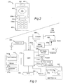
- the mobile terminal 200 comprises an apparatus housing 201, a loudspeaker 202, a display 203, an input device 204a-c, and a microphone 205.
- the input device 204a-c includes a set of keys 204a arranged in a keypad of common ITU-T type (alpha-numerical keypad), a pair of soft keys or function keys 204b, and a biometrical data reader 204c in the form of a fingerprint sensor.
- a graphical user interface 206 is provided, which may be used by a user of the mobile terminal 200 to control the terminal's functionality and get access to any of the telecommunications services referred to above, or to any other software application executing in the mobile terminal.
- the keypad 204a may be used for entering a PIN code to be used for authenticating the key device 100 in the lock device 140 in order to decide whether or not to unlock the lock controlled by the lock device.
- the biometrical data reader 204c is used correspondingly to produce a digital fingerprint sample from the user, said fingerprint sample being used for authenticating the key device 100 in the lock device 140 by matching with prestored fingerprint templates.
- the mobile terminal 200 of course comprises various internal hardware and software components, such as a main controller (implemented e.g. by any commercially available Central Processing Unit (CPU), Digital Signal Processor (DSP) or any other electronic programmable logic device); associated memory, such as RAM memory, ROM memory, EEPROM memory, flash memory, hard disk, or any combination thereof; various software stored in the memory, such as a real-time operating system, a man-machine or user interface, device drivers, and one or more various software applications, such as a telephone call application, a contacts application, a messaging application, a calendar application, a control panel application, a camera application, a mediaplayer, a video game, a notepad application, etc; various I/O devices other than the ones shown in Fig 2 , such as a vibrator, a ringtone generator, an LED indicator, volume controls, etc; an RF interface including an internal or external antenna as well as appropriate radio circuitry for establishing and maintaining an RF link to
- a main controller implemented e.g
- the mobile terminals 100, 106 are connected to a mobile telecommunications network 110 through RF links 103, 108 via base stations 104, 109.
- the mobile telecommunications network 110 may be in compliance with any commercially available mobile telecommunications standard, such as GSM, UMTS, D-AMPS or CDMA2000.
- the mobile telecommunications network 110 is operatively connected to a wide area network 120, which may be Internet or a part thereof.
- a wide area network 120 which may be Internet or a part thereof.
- client computers and server computers including a system server 122, may be connected to the wide area network 120.
- a public switched telephone network (PSTN) 130 is connected to the mobile telecommunications network 110 in a familiar manner.
- Various telephone terminals, including a stationary telephone 132, may be connected to the PSTN 130.
- the lock device 140 will be described in more detail.
- the door 150 is shown in more detail.
- the door has a lock 160 which includes an internal lock mechanism and which is only schematically indicated in Fig 4 .
- a door handle 161, a lock knob 162 and a lock catch 163 are also provided.
- the lock knob 162 is mounted to one end of a rotatable axle 164 which is coupled to or engages with the internal lock mechanism of the lock 160.
- the lock device 140 is mounted to a base plate 154 which is attached to the door leaf 152 next to the lock 160.
- a user may manually unlock the door lock 160, from the inside of the premises which are protected by the door 150, by turning the lock knob 162. This will cause rotation of the axle 164, actuation of the internal lock mechanism of the lock 160, and, ultimately, retraction of the lock catch 163 from its extended locking position in Fig 4 to a retracted releasing position.
- the door lock 160 may also be automatically unlocked by the lock device 140 by the following arrangements.
- a first gear wheel 166 is provided for actuation of the rotatable axle 164 via disengageable carrier means (not shown in Fig 5 ).
- the first gear wheel 166 engages with a second, smaller gear wheel 308b which in turn is fixedly mounted to a rotatable axle 308a of an electric motor 308 inside a protective casing 144 of the lock device 140.
- a motor controller 307 ( Fig 3 ) is coupled to the motor 308 and is adapted to provide a control signal 307b for engaging or disengaging the motor 308 and the aforementioned carrier means.
- the motor controller 307 is controlled by a control signal 307a from a CPU 313 in the lock device 140.
- An encoder 306 is provided to assist the CPU 313 in monitoring the current angular position of the gear wheel 166 so as to select appropriate duration of the control signal 307a and achieve sufficient retraction of the lock catch 163 by the mechanical power provided by the motor 308 and translated into turning of the rotatable axle 164 via the first and second gear wheels 166, 308b and the carrier means.
- these elements form a lock actuator 170 which is controllable by the motor controller 307 and CPU 313.
- the CPU 313 is programmed to read and execute program instructions stored in a memory 311 so as to perform a method for wireless automatic unlocking of the lock 160 in response to the appearance and proper authentication of the key device 100.
- An embodiment of this method is illustrated in Figs 6 and 7 and will be described in more detail later.
- the lock device 140 is a stand-alone, autonomously operating device which requires no wire-based installations, neither for communication nor for power supply. Instead, the lock device 140 is powered solely by a local battery power unit 303 and interacts with the key device, as already mentioned, by BluetoothTM-based activities. To this end, the lock device 140 has a Bluetooth TM radio module 309 with an antenna 310.
- the lock device 140 of the present embodiment further includes a real-time clock 304 capable of providing the CPU 313 which an accurate value of the current time.
- a detector 312b is positioned to detect that the door 150 is in a properly closed position, so that the CPU 313 may command locking of the lock 160 a certain time after a user has opened the door through the key device 100 and passed therethrough.
- the detector 312b may be a conventional magnetic switch having a small magnet mounted to the door frame and a magnetic sensor mounted at a corresponding position on the door leaf 152.
- the carrier means is disengaged, so that the lock knob 162 may be actuated manually from the inside of the premises to lock or unlock the door lock 160 without mechanical resistance from the electromechanical elements of the lock actuator 170.
- these elements may be replaced by an electric step motor positioned and adapted to actuate the axle 164 directly.
- the aforesaid carrier means may be dispensed with.
- the lock device 140 may have a simple user interface involving button(s) 305, a buzzer 312a and LED indicator(s) 312c.
- an authorized administrator may configure the lock device 140 through this user interface.
- configuration of the lock device 140 - including updating the contents of a local database (LD-DB) 142 stored in memory 311 and containing i.a. key device authentication data - occurs wirelessly either directly from a proximate mobile terminal 106 over a Bluetooth TM link 116, or by supplying a key device, for instance key device 100, with authentication data updating information from a system database 124 at the system server 122 over the mobile telecommunications network 110.
- LD-DB local database
- the lock device 140 Since the lock device 140 is a stand-alone, battery-powered installation which is intended to be operative for long time periods without maintenance, it is important to keep power consumption at a minimum. Therefore, the present embodiment is designed to put itself in a sleep mode after a certain period of inactivity. In the sleep mode, the elements of the lock device 140 are inactive and consume negligible power. The way to exit the sleep mode and enter operational mode is by applying a wake-up control signal 326 on a particular control input on the CPU 313. To this end, the lock device 140 is provided with a wake-up arrangement 320 having a proximity sensor 324 and associated circuitry 322.
- the proximity sensor 324 is positioned to detect the presence of a user in a vicinity of the lock device 140, and in response the circuitry 322 is adapted to generate the wake-up control signal 326.
- the proximity sensor 324 may for instance be an IR (Infra-Red) sensor, an ultra-sound sensor, an optical sensor, an RF (Radio Frequency) sensor or a pressure sensor.
- IR Infra-Red
- RF Radio Frequency
- a pressure sensor Such types of sensors are all well known to the skilled person and are commercially available.
- the proximity sensor 324 is an RF sensor, it may advantageously be adapted to detect mobile telecommunications traffic, such as GSM traffic, to or from the mobile terminal which implements the key device 100.
- the proximity sensor 324 does not detect the user himself but the key device 100 he carries.
- the proximity sensor 324 is a pressure sensor, it may advantageously be located at floor level somewhere near the door 150, so as to detect pressure variations caused by the user when
- the proximity sensor 324 may be positioned on or at the door handle 161 and be adapted to generate a detection signal by electrically detecting interaction from the user on the door handle, for instance by capacitive means or by detecting the closure of an electric circuit.
- the wake-up arrangement 320 has an acoustic or vibration sensor 324 which is adapted to detect door knocks on the door leaf 152.
- a sensor may be provided in the form of a microphone which is attached via a spacer to the door leaf 152. The spacer will transfer vibrations caused by door knocks to the microphone.
- the circuitry 322 may be programmed or designed to apply predetermined wake-up criteria when decided whether or not to generate the wake-up control signal 326.
- wake-up criteria may for instance be the detection of more than one door knock within a certain time frame. This may prevent an accidental wake-up because of a spurious detection of a non-related sound from the environment. Even more advanced wake-up criteria may be used, such as a given sequence of short and long door knocks, much like a code of Morse signals.
- a door bell device is integrated with the lock device 140.
- the CPU 313 may determine whether or not an acoustic door bell sound is to be generated (for instance during morning, day and evening times) or not (for instance during night time) when a door bell button of the door bell device is pressed.
- the door bell device may be used as the sensor 324 of the wake-up arrangement 320, such that an input signal is supplied to the circuitry 322 when the door bell button is pressed. It is alternatively possible to let the door bell device replace the entire circuitry 322, such that the wake-up control signal 326 is generated directly from a door bell button switch.
- means such as a depressible button may be provided on or at the door 150 on the inside of the premises in question.
- the user may avail himself of such means to cause forced unlocking of the door lock 160 when he desires to leave the premises.
- such means will be coupled to the CPU 313, and the latter will be adapted to perform the forced unlocking of the door lock 160 by generating the control signal 307b to the motor controller 307 so as to control the motor 308 in the manner previously described.
- the method consists of two main authentication stages 620 and 640, and, in the present embodiment but optionally, an initial wake-up stage 610.
- the first authentication stage 620 is designed to be fast and therefore does not involve any establishment of a two-way Bluetooth TM communication link between lock device and key device, in contrast to the prior art approach described in the introductory section of this document.
- the first authentication stage resulting in the opening of a door, may be completed in as little time as 2-4 seconds, which is considerably faster than in the prior art.
- authorization is based solely on the key device's Bluetooth TM address and the current time, both of which are detected automatically by the lock device 140 and require no interaction from the user (other than bringing the key device 100 near the door 150).
- Certain prioritized users are entrusted to unlock the door 150 simply through this first authentication stage 620, whereas other users must be authorized during the following, second and more extensive authentication stage 640 which requires establishment of a two-way Bluetooth TM communication link and involves additional verification data from the key device 100 - in the form of a PIN code in the present embodiment.
- the lock device 140 bases its operation upon the authentication data stored in LD-DB 142.
- the record structure of the LD-DB 142 includes the following data fields for authentication data: Field Contents example #1 Contents example #1 LD ID 121 121 User name Olle Johan Bluetooth TM ID 0x00223af3 0x002e5af4 Stage-1 time slot (1) 2005-03-24: 19-22 Stage-1 time slot (2) Mon-Fri: 07-15 ... Stage-1 time slot (n) Stage-2 time slot - single Stage-2 time slot - scheduled 00-24 Sat-Sun: 10-18 PIN code **** **** Administrator No No No
- Stage-2 authentication requires a special software in the key device 100, since data exchange is involved. Therefore, if mobile terminals are used as key devices, they are preferably of an advanced model provided with a suitable operating system, such as Symbian, at least for users that require stage-2 authentication.
- the PIN code it may either be prestored in memory in the key device 100 and fetched by the software therein upon communication to the lock device, or the software may invite the user to enter his PIN code manually on e.g. the keypad 204a upon establishment of the two-way Bluetooth TM communication link.
- biometric data instead of PIN code is used as verification data, they are treated in the corresponding way, i.e. either prestored in memory or read by e.g. the fingerprint sensor 204c. It is to be observed that all communication between key device and lock device is encrypted in accordance with an encryption algorithm, such as Blowfish. Therefore, data integrity is ascertained.
- the initial wake-up stage 610 is performed in steps 612, 614 and 616 by using the proximity sensor 324 to detect the presence of the user of key device 100 near the lock device 140 and in response generate the wake-up control signal 326 to the CPU 313.
- a step 622 searches for BluetoothTM-enabled devices by paging, i.e. sending inquiry requests at regular intervals.
- Each BluetoothTM-enabled device within operating range i.e. within a radius of some meters from the lock device 140, depending on e.g. the output power of the Bluetooth TM radio module 309 and the performance of the Bluetooth TM transceivers in the devices paged for
- step 628 proceeds to determine the Bluetooth TM address from the inquiry response. Moreover, a current time is determined by reading a value from the real-time clock 304.
- the CPU 313 proceeds in step 630 to check whether the determined Bluetooth TM address of the responding device matches one of aforedescribed authentication data records in the LD-DB 142. In case of a match, it is also checked whether the current time falls within any stage-1 time slot defined for that Bluetooth TM address. If the outcome of these checks is fully positive, as checked in step 632, the CPU 313 proceeds to step 634 and generates the control signal 307a to the motor controller 307. As described above, this will cause unlocking of the door lock 160 and allow the door 150 to be opened.
- step 632 If the check in step 632 reveals that the determined Bluetooth TM address is not present in the LD-DB 142, or that the Bluetooth TM address is present but the current time matches neither a stage-1 time slot nor a stage-2 time slot for that address, then the door lock 160 will not be unlocked, and the execution will return to step 622. In some embodiments it is possible to list certain undesired Bluetooth TM addresses as explicitly forbidden in LD-DB 142. If the determined Bluetooth TM address matches such a forbidden Bluetooth TM address, appropriate action may be taken in a step 636, such as generating an alarm signal or registering the access attempt in memory 311 for later reporting.
- step 632 If the check in step 632 reveals that the determined Bluetooth TM address is present in the LD-DB 142, but that the current time does not fall within any stage-1 time slot defined for that Bluetooth TM address but only within a stage-2 time slot, the execution proceeds to step 640.
- step 640 the CPU controls the Bluetooth TM radio module 309 to establish a two-way Bluetooth TM communication link with the key device 100 detected in step 628.
- step 642 data transmitted by the software in the key device 100 is received in the lock device 140.
- step 644 extracts verification data, such as a PIN code for key device 100, which as previously explained is included in the received data.
- step 646 it is checked whether the extracted verification data matches the corresponding authentication data stored for the key device's Bluetooth TM address in LD-DB 142.
- step 648 the CPU 313 proceeds to step 650 and generates the control signal 307a to the motor controller 307. Again, this will cause unlocking of the door lock 160 and allow the door 150 to be opened.
- step 640 it may be checked in a step 710 whether the data received from the key device 100 contains authentication data updating information for the intention of updating the authentication data records stored in LD-DB 142, for instance in order to reflect the addition of a new user/key device at the system server 122, or a change in authority for an existing user - e.g. a change in its stage-1 or stage-2 time slot.
- Such updating information may have been distributed to the key device 100, as well as to other key devices in the system, from the system server 122 over the mobile telecommunications network 110, for instance as an attachment in an MMS or email message.
- Updating information originating from the system server 122 (system DB 124) is encrypted before transmission to the key device 100 (if not already when stored in system DB 124), and upon reception the key device 100 stores the updating information as an encrypted dataset in local memory (KD-DB 102).
- KD-DB 102 local memory
- a system time stamp is preferably included in the updating information distributed from the system server 122, and the key device may store the updating information with a key device time stamp in its KD-DB 102, said key device time stamp representing the time of receipt of the updating information from the system server in the key device.
- step 712 the CPU 313 proceeds to step 714 so as to update the contents of the LD-DB with the updating information received from the key device 100.
- the CPU 313 preferably determines a time stamp of the received updating information, such as the aforementioned system time stamp and/or key device time stamp, and compares it or them to a cur-rent time stamp for the present authentication data in the LD-DB 142. Only if according to this comparison the updating information from the key device 100 is newer will the actual update in LD-DB 142 take place.
- the CPU 313 may choose to allow updating of the LD-DB 142 only if the current time stamp of the LD-DB 142 is older than both the key device time stamp and the system time stamp, and if the key device time stamp is newer than the system time stamp.
- step 646 Performing such updating of the LD-DB 142 prior to performing the authentication check of the key device 100 in step 646 allows the key device to bring about updating information that may actually change the outcome of its own authentication. For instance, if the key device 100 belongs to a new user which has not previously been represented in the LD-DB, it may nevertheless bring about updating information that will give itself stage-1 or stage-2 authority after the update of the LD-DB.
- a condition is, of course, that authentication data for that key device has been duly created by the administrator at the server 122 and has reached the key device 100 prior to the arrival thereof at the lock device 140.
- step 632 will be followed by an attempt for stage-2 authentication in step 640, even if no matching Bluetooth TM address is found during stage-1 authentication.
- Another optional step 716 involves compiling historic data about previous accesses to the door 150 through the lock device 140.
- Such historic data may have been created by the CPU 313 each time a key device has been subjected to authentication by the lock device 140 and may comprise the detected Bluetooth TM address of each such key device, and a time stamp representing the time it happened.
- Such historic data may be stored in an event register in the LD-DB 142.
- a log file and/or statistics may be generated by reading the historic data from the event register. The log file and/or statistics is/are transmitted as a dataset to the key device 100 in step 718.
- the software in the key device 100 may store the dataset in its KD-DB 102 for immediate or later forwarding to the system server 122 over the mobile telecommunications network 110, essentially like the distribution of aforesaid updating information but in the reverse order and direction.
- the administrator may analyze such log file and/or statistics not only for the lock device 140 but also for other lock devices in the system, thereby being given an overview of the operational situation in the entire system.
- step 634 the execution may proceed to step 638, in which a two-way Bluetooth TM communication link is established, and then with the above-described steps of Fig 7 so as to exchange authentication data updating information and/or statistics/log file data with the key device 100.
- the lock device 140 is physically divided into two units.
- a first unit capable of wireless communication such as Bluetooth TM
- the first unit need not be optimized in terms of power consumption.
- the first unit is capable of performing the afore-described first and, if applicable, second authentication stages for an available key device and generate a control signal to a second unit, which will be mounted at the lock in question and cause unlocking of its lock mechanism upon receipt of a successful control signal from the first unit.
- the second unit will contain the electromechanical elements necessary to perform this task.
- the second unit is advantageously battery-powered and adapted to receive the control signal from the first unit over a wireless interface, such as Bluetooth TM .
- One first unit may be configured to handle and control several second units, each mounted at a respective door, window, etc - the first unit thereby functioning like a central locking device.
- the key device 100 may contain software that requires the user to regularly enter a security code, such a PIN code at least once every hour. If no correct PIN code is entered in time, the key device 100 may be adapted to disable for instance its Bluetooth functionality. This will prevent misuse in case the key device 100 gets stolen or otherwise lost and minimizes the risk that an unauthorized individual gets access to the space or premises protected by the lock 160.
- the software of the key device 100 may also be susceptible of an incoming disable command over the link 103, contained for instance in an SMS, MMS or email message from the system server 122, allowing the administrator of the server 122 to disable the key device 100 from remote if necessary.
- the invention has mainly been described above with reference to a few embodiments. However, as is readily appreciated by a person skilled in the art, other embodiments than the ones disclosed above are equally possible within the scope of the invention, as defined by the appended patent claims. For instance, even if the disclosed embodiments relate to opening of doors, the invention may just as well be used for controlling other kind of objects, including but not limited to garage ports and various other equipment at homes, offices or public buildings. A medicine cabinet is one example of such an object that may be protected by the invention. Moreover, the invention may be used for wireless actuation of a safety lock of the well known "safety chain" type, i.e.
- a lock which has three primary positions: a locked position, an open or unlocked position, and a safety position in which the protected door, window, etc, can be opened only a short distance.
- a safety lock is found in WO 04/083576 .
- Bluetooth TM for the short-range wireless data communication
- another communication standard is also feasible, including but not limited to IrDA or a wireless local area network (WLAN) standard such as IEEE 802.11, IEEE 802.11a, IEEE 802,11b, IEEE 802.11g, HiperLAN2, WiMAX (IEEE 802.16), or HomeRF.
- WLAN wireless local area network
- a further aspect of the present disclosure is a method for unlocking a lock by a lock device enabled for short-range wireless data communication in compliance with a communication standard, the method comprising the steps of:
- Steps a) and b) of detecting and determining are performed without any establishment of a two-way communication link between lock device and key device pursuant to said communication standard, and therefore the unlocking method according to the first aspect is much faster than the unlocking method known from the prior art previously referred to in this document. Moreover, it will allow also less advanced wireless communication devices to act as key devices.
- the communication standard is preferably BlueToothTM, and steps a) and b) may thus involve:
- Step b) may further involve determining a current time; and steps c) and d) may further involve comparing said current time with a number of time slots associated with a particular one of the stored wireless communication addresses that matches the determined wireless communication address of the key device, a requisite for a positive evaluation result being that the current time falls within any of said time slots.
- the wireless communication addresses stored in the data storage may be associated with respective authority levels, wherein steps c) and d) may involve:
- Time slots are preferably provided in first and second types, said first type of time slot representing a first authority level which meets or exceeds said predetermined authority level, and said second type of time slot representing a second authority level which is below said predetermined authority level, the method involving the step of deciding that said authority level associated with said particular address is said first authority level if said current time falls within at least one time slot which is of said first type and is associated with said particular address.
- the verification data may include a PIN (Personal Identification Number) code, or biometric data in the form of e.g. a digital fingerprint sample.
- PIN Personal Identification Number
- biometric data in the form of e.g. a digital fingerprint sample.
- the method may further involve the introductory steps of detecting the presence of a user in a vicinity of said lock device and in response triggering performance of step a).
- This allows the lock device to rest in a sleep mode with negligible power consumption during periods of inactivity. Only elements that handle the detection of the user's presence will need to be active during such a sleep mode.
- optimum power preservation allows implementing the lock device as a stand-alone device that may operate autonomously for long periods of time, powered by its own power source such as batteries.
- the presence of the user may be detected by receiving a detection signal from a proximity sensor positioned and adapted to monitor the vicinity of said lock device.
- the proximity sensor may be selected from the group consisting of: an IR (Infra-Red) sensor, an ultra-sound sensor, an optical sensor, an RF (Radio Frequency) sensor, a pressure sensor, a capacitive sensor, an acoustic sensor or a vibration sensor.
- the proximity sensor may be positioned on or at said door handle and be adapted to generate said detection signal by electrically detecting interaction from said user on said door handle.
- a step of storing said wireless communication address, as determined in step b), in said data storage allows generation of a log file and/or statistics by collecting wireless communication addresses for different key devices as stored in the data storage; and transmission of said log file and/or statistics to said key device over said communication link.
- the method may involve the steps of
- Still an aspect of the present disclosure is a lock actuating device for a lock mechanism of a lock, the lock actuating device comprising:
- the lock actuating device may further comprise a real-time clock capable of providing the controller with a current time value, wherein the controller is configured, during the first authorization, to evaluate said current time value with respect to data in said data storage to determine whether said current time matches an allowable time period defined by said data for the wireless communication address of said present key device, a requisite for said possible first outcome being a match between said current time value and said allowable time period.
- a real-time clock capable of providing the controller with a current time value
- the controller is configured, during the first authorization, to evaluate said current time value with respect to data in said data storage to determine whether said current time matches an allowable time period defined by said data for the wireless communication address of said present key device, a requisite for said possible first outcome being a match between said current time value and said allowable time period.
- the controller has a sleep mode and an operational mode
- the lock actuating device further comprising a wake-up arrangement including a sensor and associated circuitry, the sensor being positioned to detect the presence of a user in a vicinity of the lock actuating device, and the circuitry being adapted to generate a wake-up control signal to the controller upon detection of said user, so as to cause the controller to switch from sleep mode to operational mode.
- Yet another aspect of the present disclosure is a lock device for unlocking a lock, the lock device having:
Abstract
Description
- The present invention generally relates to access control, and more specifically to a lock actuating device for a lock mechanism of a lock. The invention also relates to a method of providing wireless control of a lock.
- The most common way to lock and unlock an access-controlling object such as a door is probably by using a mechanical key. This solution is cost efficient and easy to use, and a sophisticated mechanical lock is hard to force. However, there are two drawbacks with this solution: the user always has to bring the key and the key does not have any restrictions, i.e. it always works.
- These drawbacks might seem like minor disadvantages, which might be true in situations with one user and one door, but in situations with a large number of users and a large number of doors the drawbacks are of considerable importance. In more particular, if a large number of users must have access to a large number of doors, a large number of keys has to be made for the different doors. This is not only unhandy but also a considerable security risk and costly.
- Firstly, in order to reduce the security risk, some sort of key administration is necessary. This type of administration is costly.
- Secondly, a user who receives a key might abuse it, and even if the user is a responsible person, the key might be stolen or lost. Since there are no built-in restrictions in a mechanical key the security risk becomes significant. Consequently, handing out a large number of keys is a security risk.
- Thirdly, if one of the keys is lost or stolen the corresponding lock has to be substituted, as well as all the other corresponding keys, in order to maintain the security. The administration costs, locksmith costs and all interruptions due to these key substitutions imply considerable costs for a lost key.
- A mechanical key system is hence not suitable for situations with a large number of users and a large number of doors. An example of such a situation is the elderly home care, where the domestic help personnel has a key to each of the care-takers. In order to solve this problem another type of locking system is necessary.
- In
WO 02/31778 A1 - In order to function, the wireless lock system mentioned above must always establish a two-way wireless communication link between the key and the lock. This is a drawback, since the establishment of a two-way communication link is not made instantly. Hence, a user has to wait for a period of time until the establishment of the two-way communication link is completed, and thereafter the user has to wait until the comparison is completed. The present inventors have realized that if the wireless lock system in
WO 02/31778 A1 WO 02/31778 A1 - Users who are used to mechanical keys are not used to wait at the door, which will make the aforementioned waiting period into a source of irritation. In addition, if a large number of doors is to be opened every day the unlocking process must be smooth and easy.
- Hence, it must be regarded as a qualified technical problem to reduce the time that lapses from the lock's detection of a nearby electronic key until the unlocking of the lock, or more particularly the delay that a user may experience waiting in front of the lock for it to unlock.
- A natural way for the skilled person to solve this problem would be to increase the transmission power of the Bluetooth™ transceivers in the lock and key, since this would broaden the operating range thereof and allow earlier detection of an approaching key by the lock (such that the key will be detected already when the approaching user is at e.g. a 20 meter distance from the lock instead of e.g. a 10 meter distance), wherein the two-way link establishment may be initiated sooner and possibly be completed at the time when the user has reached the lock.
- However, this solution has two pronounced drawbacks. First of all, the increased transmission power has an immediate penalty in the form of an increase in electric power consumption, which is particularly disadvantageous for battery-powered locks and keys. Secondly, the broadened operating range invites also other locks than the intended one to detect and interact with the key - in other words, the risk of cross-talk is increased.
- In summary, there is a need for a flexible lock system arranged to work in situations with many users and many doors, and with a faster unlocking process.
-
EP-0 735 219 discloses a lock actuating device similar to the preamble of the attachedindependent claim 1. - In view of the above, an objective of the invention is to solve or at least reduce one or more of the problems discussed above.
- This is achieved by a lock actuating device and a method of providing wireless control of a lock according to the attached independent patent claims.
- Other objectives, features and advantages of the present invention will appear from the following detailed disclosure, from the attached dependent claims as well as from the drawings.
- Generally, all terms used in the claims are to be interpreted according to their ordinary meaning in the technical field, unless explicitly defined otherwise herein. All references to "a/an/the [element, device, component, means, step, etc]" are to be interpreted openly as referring to at least one instance of said element, device, component, means, step, etc., unless explicitly stated otherwise. The steps of any method disclosed herein do not have to be performed in the exact order disclosed, unless explicitly stated.
- The above, as well as additional objectives, features and advantages of the present invention, will be better understood through the following illustrative and non-limiting detailed description of embodiments of the present invention, with reference to the appended drawings, where the same reference numerals will be used for similar elements.
-
Fig 1 is a schematic illustration of a telecommunication system, including a wireless key device implemented by a mobile terminal, an embodiment of a wireless lock device for a lock in a door, a wireless administrator device implemented by a mobile terminal, an administrator server, a mobile telecommunications network and a couple of other elements, as an example of an environment in which the present invention may be applied. -
Fig 2 is a schematic front view illustrating the wireless key device ofFig 1 , and in particular some external components that are part of a user interface towards a user of the wireless key device. -
Fig 3 is a schematic block diagram illustrating internal components and modules of the embodiment of the wireless lock device shown inFig 1 . -
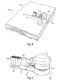
Fig 4 is a perspective sectional view of the lock device ofFig 1 , mounted to the door ofFig 1 . -
Fig 5 is a perspective and exploded view of the lock device ofFig 4 . -
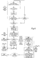
Figs 6 and7 are flowchart diagrams of a method performed by the the lock device for unlocking the lock by actuating a lock mechanism thereof. - The present invention is advantageously implemented in a mobile telecommunications system, one example of which is illustrated in
Fig 1 . Central elements inFig 1 are a wireless key device (KD) 100 and a wireless lock device (LD) 140. The purpose of thelock device 140 is to control some sort of lock mechanism in a lock, which in the illustrated example is a door lock on adoor 150. In turn, thelock device 140 is operated by the key device when brought in the vicinity of the lock device. In more particular, both thekey device 100 and thelock device 140 are enabled for short-range wireless data communication in compliance with a communication standard. In the preferred embodiment, this communication standard is Bluetooth™. Having been the de facto standard for short-range wireless data communication for mobile devices during several years already, Bluetooth™ is believed to be very well known to the skilled person, and no particulars about Bluetooth™ as such are consequently given herein. - As with most other contemporary mobile telecommunications systems, the system of
Fig 1 provides various telecommunications services such as voice calls, data calls, facsimile transmissions, music transmissions, still image transmissions, video transmissions, electronic message transmissions and electronic commerce for mobile terminals in the system, such as aforementionedmobile terminal 100, anothermobile terminal 106, personal digital assistants (PDA) or portable computers. It is to be noticed that these various telecommunications services are not central to the invention, and for different embodiments, different ones of the telecommunications services may or may not be available. - In
Fig 1 , thekey device 100 is implemented by any commercially available, Bluetooth™-enabledmobile terminal 100, oneembodiment 200 of which is shown inFig 2 . As seen inFig 2 , and as is well known in the art, themobile terminal 200 comprises anapparatus housing 201, aloudspeaker 202, adisplay 203, aninput device 204a-c, and amicrophone 205. In the disclosed embodiment, theinput device 204a-c includes a set ofkeys 204a arranged in a keypad of common ITU-T type (alpha-numerical keypad), a pair of soft keys orfunction keys 204b, and abiometrical data reader 204c in the form of a fingerprint sensor. Hence, agraphical user interface 206 is provided, which may be used by a user of themobile terminal 200 to control the terminal's functionality and get access to any of the telecommunications services referred to above, or to any other software application executing in the mobile terminal. With particular reference to one embodiment of the present invention, thekeypad 204a may be used for entering a PIN code to be used for authenticating thekey device 100 in thelock device 140 in order to decide whether or not to unlock the lock controlled by the lock device. In another embodiment, thebiometrical data reader 204c is used correspondingly to produce a digital fingerprint sample from the user, said fingerprint sample being used for authenticating thekey device 100 in thelock device 140 by matching with prestored fingerprint templates. - In addition, but not shown in
Fig 2 , themobile terminal 200 of course comprises various internal hardware and software components, such as a main controller (implemented e.g. by any commercially available Central Processing Unit (CPU), Digital Signal Processor (DSP) or any other electronic programmable logic device); associated memory, such as RAM memory, ROM memory, EEPROM memory, flash memory, hard disk, or any combination thereof; various software stored in the memory, such as a real-time operating system, a man-machine or user interface, device drivers, and one or more various software applications, such as a telephone call application, a contacts application, a messaging application, a calendar application, a control panel application, a camera application, a mediaplayer, a video game, a notepad application, etc; various I/O devices other than the ones shown inFig 2 , such as a vibrator, a ringtone generator, an LED indicator, volume controls, etc; an RF interface including an internal or external antenna as well as appropriate radio circuitry for establishing and maintaining an RF link to a base station; aforementioned Bluetooth™ interface including a Bluetooth™ transceiver; other wireless interfaces such as WLAN, HomeRF or IrDA; and a SIM card with an associated reader. - The
mobile terminals mobile telecommunications network 110 throughRF links base stations mobile telecommunications network 110 may be in compliance with any commercially available mobile telecommunications standard, such as GSM, UMTS, D-AMPS or CDMA2000. - The
mobile telecommunications network 110 is operatively connected to awide area network 120, which may be Internet or a part thereof. Various client computers and server computers, including asystem server 122, may be connected to thewide area network 120. - A public switched telephone network (PSTN) 130 is connected to the
mobile telecommunications network 110 in a familiar manner. Various telephone terminals, including astationary telephone 132, may be connected to thePSTN 130. - Referring now to
Figs 3-5 , thelock device 140 will be described in more detail. InFig 4 , thedoor 150 is shown in more detail. In a well-known manner the door has alock 160 which includes an internal lock mechanism and which is only schematically indicated inFig 4 . Adoor handle 161, alock knob 162 and alock catch 163 are also provided. Thelock knob 162 is mounted to one end of arotatable axle 164 which is coupled to or engages with the internal lock mechanism of thelock 160. Thelock device 140 is mounted to abase plate 154 which is attached to thedoor leaf 152 next to thelock 160. - A user may manually unlock the
door lock 160, from the inside of the premises which are protected by thedoor 150, by turning thelock knob 162. This will cause rotation of theaxle 164, actuation of the internal lock mechanism of thelock 160, and, ultimately, retraction of thelock catch 163 from its extended locking position inFig 4 to a retracted releasing position. - In addition to this, and in accordance with the invention, the
door lock 160 may also be automatically unlocked by thelock device 140 by the following arrangements. To this end, afirst gear wheel 166 is provided for actuation of therotatable axle 164 via disengageable carrier means (not shown inFig 5 ). Thefirst gear wheel 166 engages with a second,smaller gear wheel 308b which in turn is fixedly mounted to arotatable axle 308a of anelectric motor 308 inside aprotective casing 144 of thelock device 140. A motor controller 307 (Fig 3 ) is coupled to themotor 308 and is adapted to provide acontrol signal 307b for engaging or disengaging themotor 308 and the aforementioned carrier means. - In turn, the
motor controller 307 is controlled by acontrol signal 307a from aCPU 313 in thelock device 140. Anencoder 306 is provided to assist theCPU 313 in monitoring the current angular position of thegear wheel 166 so as to select appropriate duration of thecontrol signal 307a and achieve sufficient retraction of thelock catch 163 by the mechanical power provided by themotor 308 and translated into turning of therotatable axle 164 via the first andsecond gear wheels lock actuator 170 which is controllable by themotor controller 307 andCPU 313. - The
CPU 313 is programmed to read and execute program instructions stored in amemory 311 so as to perform a method for wireless automatic unlocking of thelock 160 in response to the appearance and proper authentication of thekey device 100. An embodiment of this method is illustrated inFigs 6 and7 and will be described in more detail later. - The
lock device 140 is a stand-alone, autonomously operating device which requires no wire-based installations, neither for communication nor for power supply. Instead, thelock device 140 is powered solely by a localbattery power unit 303 and interacts with the key device, as already mentioned, by Bluetooth™-based activities. To this end, thelock device 140 has a Bluetooth™ radio module 309 with anantenna 310. - The
lock device 140 of the present embodiment further includes a real-time clock 304 capable of providing theCPU 313 which an accurate value of the current time. Adetector 312b is positioned to detect that thedoor 150 is in a properly closed position, so that theCPU 313 may command locking of the lock 160 a certain time after a user has opened the door through thekey device 100 and passed therethrough. Thedetector 312b may be a conventional magnetic switch having a small magnet mounted to the door frame and a magnetic sensor mounted at a corresponding position on thedoor leaf 152. - At the same time, preferably, the carrier means is disengaged, so that the
lock knob 162 may be actuated manually from the inside of the premises to lock or unlock thedoor lock 160 without mechanical resistance from the electromechanical elements of thelock actuator 170. In an alternative embodiment, these elements may be replaced by an electric step motor positioned and adapted to actuate theaxle 164 directly. Thus, in such an embodiment, on condition that the electric step motor provides only little mechanical resistance, the aforesaid carrier means may be dispensed with. - The
lock device 140 may have a simple user interface involving button(s) 305, abuzzer 312a and LED indicator(s) 312c. In some embodiments, an authorized administrator (ADM) may configure thelock device 140 through this user interface. In other embodiments, though, configuration of the lock device 140 - including updating the contents of a local database (LD-DB) 142 stored inmemory 311 and containing i.a. key device authentication data - occurs wirelessly either directly from a proximatemobile terminal 106 over a Bluetooth™ link 116, or by supplying a key device, for instancekey device 100, with authentication data updating information from asystem database 124 at thesystem server 122 over themobile telecommunications network 110. - Since the
lock device 140 is a stand-alone, battery-powered installation which is intended to be operative for long time periods without maintenance, it is important to keep power consumption at a minimum. Therefore, the present embodiment is designed to put itself in a sleep mode after a certain period of inactivity. In the sleep mode, the elements of thelock device 140 are inactive and consume negligible power. The way to exit the sleep mode and enter operational mode is by applying a wake-up control signal 326 on a particular control input on theCPU 313. To this end, thelock device 140 is provided with a wake-uparrangement 320 having aproximity sensor 324 and associatedcircuitry 322. - The
proximity sensor 324 is positioned to detect the presence of a user in a vicinity of thelock device 140, and in response thecircuitry 322 is adapted to generate the wake-upcontrol signal 326. Theproximity sensor 324 may for instance be an IR (Infra-Red) sensor, an ultra-sound sensor, an optical sensor, an RF (Radio Frequency) sensor or a pressure sensor. Such types of sensors are all well known to the skilled person and are commercially available. For instance, when theproximity sensor 324 is an RF sensor, it may advantageously be adapted to detect mobile telecommunications traffic, such as GSM traffic, to or from the mobile terminal which implements thekey device 100. Thus, in this case theproximity sensor 324 does not detect the user himself but thekey device 100 he carries. When theproximity sensor 324 is a pressure sensor, it may advantageously be located at floor level somewhere near thedoor 150, so as to detect pressure variations caused by the user when stepping on the floor. - Alternatively, the
proximity sensor 324 may be positioned on or at thedoor handle 161 and be adapted to generate a detection signal by electrically detecting interaction from the user on the door handle, for instance by capacitive means or by detecting the closure of an electric circuit. - In one embodiment, the wake-up
arrangement 320 has an acoustic orvibration sensor 324 which is adapted to detect door knocks on thedoor leaf 152. Such a sensor may be provided in the form of a microphone which is attached via a spacer to thedoor leaf 152. The spacer will transfer vibrations caused by door knocks to the microphone. Thecircuitry 322 may be programmed or designed to apply predetermined wake-up criteria when decided whether or not to generate the wake-upcontrol signal 326. Such wake-up criteria may for instance be the detection of more than one door knock within a certain time frame. This may prevent an accidental wake-up because of a spurious detection of a non-related sound from the environment. Even more advanced wake-up criteria may be used, such as a given sequence of short and long door knocks, much like a code of Morse signals. - In one embodiment, a door bell device is integrated with the
lock device 140. Making use of the real-time clock 304, theCPU 313 may determine whether or not an acoustic door bell sound is to be generated (for instance during morning, day and evening times) or not (for instance during night time) when a door bell button of the door bell device is pressed. In addition, the door bell device may be used as thesensor 324 of the wake-uparrangement 320, such that an input signal is supplied to thecircuitry 322 when the door bell button is pressed. It is alternatively possible to let the door bell device replace theentire circuitry 322, such that the wake-upcontrol signal 326 is generated directly from a door bell button switch. - Additionally, means such as a depressible button may be provided on or at the
door 150 on the inside of the premises in question. The user may avail himself of such means to cause forced unlocking of thedoor lock 160 when he desires to leave the premises. To this end, such means will be coupled to theCPU 313, and the latter will be adapted to perform the forced unlocking of thedoor lock 160 by generating thecontrol signal 307b to themotor controller 307 so as to control themotor 308 in the manner previously described. - Referring now to
Figs 6 and7 , an operational method performed by thelock device 140 for wireless automatic unlocking of thelock 160 will now be described in detail. - On a general level, the method consists of two main authentication stages 620 and 640, and, in the present embodiment but optionally, an initial wake-up
stage 610. Thefirst authentication stage 620 is designed to be fast and therefore does not involve any establishment of a two-way Bluetooth™ communication link between lock device and key device, in contrast to the prior art approach described in the introductory section of this document. Experiments have indicated that the first authentication stage, resulting in the opening of a door, may be completed in as little time as 2-4 seconds, which is considerably faster than in the prior art. - In the first authentication stage, authorization is based solely on the key device's Bluetooth™ address and the current time, both of which are detected automatically by the
lock device 140 and require no interaction from the user (other than bringing thekey device 100 near the door 150). Certain prioritized users are entrusted to unlock thedoor 150 simply through thisfirst authentication stage 620, whereas other users must be authorized during the following, second and moreextensive authentication stage 640 which requires establishment of a two-way Bluetooth™ communication link and involves additional verification data from the key device 100 - in the form of a PIN code in the present embodiment. - The
lock device 140 bases its operation upon the authentication data stored in LD-DB 142. In the present embodiment, the record structure of the LD-DB 142 includes the following data fields for authentication data:Field Contents example # 1Contents example # 1LD ID 121 121 User name Olle Johan Bluetooth™ ID 0x00223af3 0x002e5af4 Stage-1 time slot (1) 2005-03-24: 19-22 Stage-1 time slot (2) Mon-Fri: 07-15 ... Stage-1 time slot (n) Stage-2 time slot - single Stage-2 time slot - scheduled 00-24 Sat-Sun: 10-18 PIN code **** **** Administrator No No - In the example given above, it is thus configured that user Olle is authorized to open the
door 150, through thelock device 140 having ID 121, by using hiskey device 100 having Bluetooth™ ID 0x00223af3 by fast stage-1 authentication during working days between 07:00 and 15:00. He is also granted a temporary stage-1 authority on 24 March 2005 between 19:00 and 22:00. If he arrives at the door outside of these stage-1 time slots, he may still access thedoor 150 at any time (00-24), but in such a case he must go through a more complex stage-2 authentication which involves additional authorization, namely by providing a PIN code from thekey device 100 and having it communicated to thelock device 140 over a two-way Bluetooth™ communication link. Stage-2 authentication requires a special software in thekey device 100, since data exchange is involved. Therefore, if mobile terminals are used as key devices, they are preferably of an advanced model provided with a suitable operating system, such as Symbian, at least for users that require stage-2 authentication. As regards the PIN code, it may either be prestored in memory in thekey device 100 and fetched by the software therein upon communication to the lock device, or the software may invite the user to enter his PIN code manually on e.g. thekeypad 204a upon establishment of the two-way Bluetooth™ communication link. In other embodiments, if biometric data instead of PIN code is used as verification data, they are treated in the corresponding way, i.e. either prestored in memory or read by e.g. thefingerprint sensor 204c. It is to be observed that all communication between key device and lock device is encrypted in accordance with an encryption algorithm, such as Blowfish. Therefore, data integrity is ascertained. - As for user Johan, only stage 2-authentication is available to him, and only on weekends between 10:00 and 18:00.
- With reference to
Fig 6 , assuming that thelock device 140 is in sleep mode, the initial wake-upstage 610 is performed insteps proximity sensor 324 to detect the presence of the user ofkey device 100 near thelock device 140 and in response generate the wake-up control signal 326 to theCPU 313. - This causes the
CPU 313 to enter thefirst authentication stage 620. Astep 622 searches for Bluetooth™-enabled devices by paging, i.e. sending inquiry requests at regular intervals. Each Bluetooth™-enabled device within operating range (i.e. within a radius of some meters from thelock device 140, depending on e.g. the output power of the Bluetooth™ radio module 309 and the performance of the Bluetooth™ transceivers in the devices paged for) will transmit an inquiry response to the lock device. It is checked instep 624 whether at least one inquiry response is received within a time limit; if not a time out 626 occurs and thelock device 140 returns to sleep mode. - If an inquiry response was received,
step 628 proceeds to determine the Bluetooth™ address from the inquiry response. Moreover, a current time is determined by reading a value from the real-time clock 304. - Then, the
CPU 313 proceeds instep 630 to check whether the determined Bluetooth™ address of the responding device matches one of aforedescribed authentication data records in the LD-DB 142. In case of a match, it is also checked whether the current time falls within any stage-1 time slot defined for that Bluetooth™ address. If the outcome of these checks is fully positive, as checked instep 632, theCPU 313 proceeds to step 634 and generates thecontrol signal 307a to themotor controller 307. As described above, this will cause unlocking of thedoor lock 160 and allow thedoor 150 to be opened. - If the check in
step 632 reveals that the determined Bluetooth™ address is not present in the LD-DB 142, or that the Bluetooth™ address is present but the current time matches neither a stage-1 time slot nor a stage-2 time slot for that address, then thedoor lock 160 will not be unlocked, and the execution will return to step 622. In some embodiments it is possible to list certain undesired Bluetooth™ addresses as explicitly forbidden in LD-DB 142. If the determined Bluetooth™ address matches such a forbidden Bluetooth™ address, appropriate action may be taken in astep 636, such as generating an alarm signal or registering the access attempt inmemory 311 for later reporting. - If the check in
step 632 reveals that the determined Bluetooth™ address is present in the LD-DB 142, but that the current time does not fall within any stage-1 time slot defined for that Bluetooth™ address but only within a stage-2 time slot, the execution proceeds to step 640. - In
step 640, the CPU controls the Bluetooth™ radio module 309 to establish a two-way Bluetooth™ communication link with thekey device 100 detected instep 628. Instep 642, data transmitted by the software in thekey device 100 is received in thelock device 140. Step 644 extracts verification data, such as a PIN code forkey device 100, which as previously explained is included in the received data. Then, instep 646 it is checked whether the extracted verification data matches the corresponding authentication data stored for the key device's Bluetooth™ address in LD-DB 142. In case of a match,step 648, theCPU 313 proceeds to step 650 and generates thecontrol signal 307a to themotor controller 307. Again, this will cause unlocking of thedoor lock 160 and allow thedoor 150 to be opened. - Once there is an established two-way Bluetooth™ communication link between
key device 100 andlock device 140, i.e. upon completion ofstep 640, it is possible to use this link for exchanging also other kind of data than aforesaid verification data. As seen inFig 7 , it may be checked in astep 710 whether the data received from thekey device 100 contains authentication data updating information for the intention of updating the authentication data records stored in LD-DB 142, for instance in order to reflect the addition of a new user/key device at thesystem server 122, or a change in authority for an existing user - e.g. a change in its stage-1 or stage-2 time slot. - Such updating information may have been distributed to the
key device 100, as well as to other key devices in the system, from thesystem server 122 over themobile telecommunications network 110, for instance as an attachment in an MMS or email message. Updating information originating from the system server 122 (system DB 124) is encrypted before transmission to the key device 100 (if not already when stored in system DB 124), and upon reception thekey device 100 stores the updating information as an encrypted dataset in local memory (KD-DB 102). Thus, the updating information is not decrypted by thekey device 100, which prevents unauthorized manipulation of the information. For further data security, a system time stamp is preferably included in the updating information distributed from thesystem server 122, and the key device may store the updating information with a key device time stamp in its KD-DB 102, said key device time stamp representing the time of receipt of the updating information from the system server in the key device. - If updating information is found in
step 712 to exist in the received data, theCPU 313 proceeds to step 714 so as to update the contents of the LD-DB with the updating information received from thekey device 100. Before this is done, however, theCPU 313 preferably determines a time stamp of the received updating information, such as the aforementioned system time stamp and/or key device time stamp, and compares it or them to a cur-rent time stamp for the present authentication data in the LD-DB 142. Only if according to this comparison the updating information from thekey device 100 is newer will the actual update in LD-DB 142 take place. For improved security, theCPU 313 may choose to allow updating of the LD-DB 142 only if the current time stamp of the LD-DB 142 is older than both the key device time stamp and the system time stamp, and if the key device time stamp is newer than the system time stamp. - Performing such updating of the LD-
DB 142 prior to performing the authentication check of thekey device 100 instep 646 allows the key device to bring about updating information that may actually change the outcome of its own authentication. For instance, if thekey device 100 belongs to a new user which has not previously been represented in the LD-DB, it may nevertheless bring about updating information that will give itself stage-1 or stage-2 authority after the update of the LD-DB. A condition is, of course, that authentication data for that key device has been duly created by the administrator at theserver 122 and has reached thekey device 100 prior to the arrival thereof at thelock device 140. To this end, in some embodiments,step 632 will be followed by an attempt for stage-2 authentication instep 640, even if no matching Bluetooth™ address is found during stage-1 authentication. - Another
optional step 716 involves compiling historic data about previous accesses to thedoor 150 through thelock device 140. Such historic data may have been created by theCPU 313 each time a key device has been subjected to authentication by thelock device 140 and may comprise the detected Bluetooth™ address of each such key device, and a time stamp representing the time it happened. Such historic data may be stored in an event register in the LD-DB 142. Instep 716, a log file and/or statistics may be generated by reading the historic data from the event register. The log file and/or statistics is/are transmitted as a dataset to thekey device 100 instep 718. Upon receipt thereof, the software in thekey device 100 may store the dataset in its KD-DB 102 for immediate or later forwarding to thesystem server 122 over themobile telecommunications network 110, essentially like the distribution of aforesaid updating information but in the reverse order and direction. In this way, at the system server the administrator may analyze such log file and/or statistics not only for thelock device 140 but also for other lock devices in the system, thereby being given an overview of the operational situation in the entire system. - In some embodiments, after a successful stage-1 unlocking in
step 634, the execution may proceed to step 638, in which a two-way Bluetooth™ communication link is established, and then with the above-described steps ofFig 7 so as to exchange authentication data updating information and/or statistics/log file data with thekey device 100. - In an alternative embodiment, the
lock device 140 is physically divided into two units. A first unit, capable of wireless communication such as Bluetooth™, is mounted at a nearby mains power socket to receive electric power therefrom. Thus, the first unit need not be optimized in terms of power consumption. The first unit is capable of performing the afore-described first and, if applicable, second authentication stages for an available key device and generate a control signal to a second unit, which will be mounted at the lock in question and cause unlocking of its lock mechanism upon receipt of a successful control signal from the first unit. Thus, the second unit will contain the electromechanical elements necessary to perform this task. The second unit is advantageously battery-powered and adapted to receive the control signal from the first unit over a wireless interface, such as Bluetooth™. Since power consumption is not an issue for the first unit, this may advantageously be adapted to scan continuously for key devices in the neighborhood, i.e. the wake-up arrangement described above may be dispensed with. This allows further miniaturization and simplification of the second unit. One first unit may be configured to handle and control several second units, each mounted at a respective door, window, etc - the first unit thereby functioning like a central locking device. - The
key device 100 may contain software that requires the user to regularly enter a security code, such a PIN code at least once every hour. If no correct PIN code is entered in time, thekey device 100 may be adapted to disable for instance its Bluetooth functionality. This will prevent misuse in case thekey device 100 gets stolen or otherwise lost and minimizes the risk that an unauthorized individual gets access to the space or premises protected by thelock 160. For improved security, the software of thekey device 100 may also be susceptible of an incoming disable command over thelink 103, contained for instance in an SMS, MMS or email message from thesystem server 122, allowing the administrator of theserver 122 to disable thekey device 100 from remote if necessary. - The invention has mainly been described above with reference to a few embodiments. However, as is readily appreciated by a person skilled in the art, other embodiments than the ones disclosed above are equally possible within the scope of the invention, as defined by the appended patent claims. For instance, even if the disclosed embodiments relate to opening of doors, the invention may just as well be used for controlling other kind of objects, including but not limited to garage ports and various other equipment at homes, offices or public buildings. A medicine cabinet is one example of such an object that may be protected by the invention. Moreover, the invention may be used for wireless actuation of a safety lock of the well known "safety chain" type, i.e. a lock which has three primary positions: a locked position, an open or unlocked position, and a safety position in which the protected door, window, etc, can be opened only a short distance. One example of such a safety lock is found in
WO 04/083576 - Further, even if the disclosed embodiments use Bluetooth™ for the short-range wireless data communication, another communication standard is also feasible, including but not limited to IrDA or a wireless local area network (WLAN) standard such as IEEE 802.11, IEEE 802.11a, IEEE 802,11b, IEEE 802.11g, HiperLAN2, WiMAX (IEEE 802.16), or HomeRF.
- A further aspect of the present disclosure is a method for unlocking a lock by a lock device enabled for short-range wireless data communication in compliance with a communication standard, the method comprising the steps of:
- a) detecting a key device within operative range of the lock device;
- b) determining a wireless communication address of the key device;
- c) evaluating the determined key device address by reference to a data storage with a number of wireless communication addresses stored therein;
- d) generating an evaluation result from said evaluating step c), wherein a match between the determined key device address and any of the wireless communication addresses stored in the data storage is a requisite for a positive evaluation result; and
- e) unlocking said lock if a positive evaluation result is generated in step d).
- Steps a) and b) of detecting and determining are performed without any establishment of a two-way communication link between lock device and key device pursuant to said communication standard, and therefore the unlocking method according to the first aspect is much faster than the unlocking method known from the prior art previously referred to in this document. Moreover, it will allow also less advanced wireless communication devices to act as key devices.
- The communication standard is preferably BlueTooth™, and steps a) and b) may thus involve:
- paging for BlueTooth™ enabled devices within operative range by sending inquiry requests;
- receiving an inquiry response from said key device; and
- obtaining said wireless communication address of said key device by reading its BlueTooth™ address from said inquiry response.
- Step b) may further involve determining a current time; and steps c) and d) may further involve comparing said current time with a number of time slots associated with a particular one of the stored wireless communication addresses that matches the determined wireless communication address of the key device, a requisite for a positive evaluation result being that the current time falls within any of said time slots.
- The wireless communication addresses stored in the data storage may be associated with respective authority levels, wherein steps c) and d) may involve:
- for a particular one of the stored wireless communication addresses that matches the determined wireless communication address of the key device, generating a first evaluation result if an authority level associated with said particular address meets or exceeds a predetermined authority level, and otherwise generating a second evaluation result,
- wherein said first evaluation result corresponds to said positive evaluation result and causes performance of step e), and
- wherein said second evaluation result causes, instead of step e), performance of the following steps:
- f) establishing a two-way communication link between said lock device and said key device pursuant to said communication standard;
- g) receiving verification data from said key device over said communication link;
- h) authenticating said key device by matching the received verification data with authentication data stored in said data storage and associated with said particular address; and
- i) upon successful authentication of said key device in step h), unlocking said lock.
- This allows handling of certain prioritized and/or trusted users according to the fast unlocking method described earlier, whereas other users may be checked more carefully by retrieving their verification data over the two-way communication link for examination in the lock device.
- Time slots are preferably provided in first and second types, said first type of time slot representing a first authority level which meets or exceeds said predetermined authority level, and said second type of time slot representing a second authority level which is below said predetermined authority level, the method involving the step of deciding that said authority level associated with said particular address is said first authority level if said current time falls within at least one time slot which is of said first type and is associated with said particular address.
- The verification data may include a PIN (Personal Identification Number) code, or biometric data in the form of e.g. a digital fingerprint sample.
- The method may further involve the introductory steps of detecting the presence of a user in a vicinity of said lock device and in response triggering performance of step a). This allows the lock device to rest in a sleep mode with negligible power consumption during periods of inactivity. Only elements that handle the detection of the user's presence will need to be active during such a sleep mode. In turn, such optimum power preservation allows implementing the lock device as a stand-alone device that may operate autonomously for long periods of time, powered by its own power source such as batteries.
- The presence of the user may be detected by receiving a detection signal from a proximity sensor positioned and adapted to monitor the vicinity of said lock device. The proximity sensor may be selected from the group consisting of: an IR (Infra-Red) sensor, an ultra-sound sensor, an optical sensor, an RF (Radio Frequency) sensor, a pressure sensor, a capacitive sensor, an acoustic sensor or a vibration sensor. Alternatively, for embodiments where the lock device is mounted to a door having a door handle, the proximity sensor may be positioned on or at said door handle and be adapted to generate said detection signal by electrically detecting interaction from said user on said door handle.
- A step of storing said wireless communication address, as determined in step b), in said data storage allows generation of a log file and/or statistics by collecting wireless communication addresses for different key devices as stored in the data storage; and transmission of said log file and/or statistics to said key device over said communication link.
- The method may involve the steps of
- receiving authentication data updating information from said key device over the communication link established in step f);
- determining a first time stamp in the authentication data updating information received, said first time stamp reflecting a time of origin for the authentication data updating information;
- determining a second time stamp for the authentication data currently stored in the data storage in the lock device; and
- updating the authentication data currently stored in the data storage in the lock device with authentication data included in the authentication data updating information received, if said first time stamp is newer than said second time stamp.
- Further steps may involve
- determining a third time stamp in the authentication data updating information received, wherein said third time stamp reflects a time of receipt of said authentication data updating information at said key device from a remote server, and wherein said first time stamp reflects a creation time of said authentication data updating information at said server; and
- performing said updating step only if said first time stamp is older than said third time stamp, and both of said first and third time stamps are newer than said second time stamp.
- Still an aspect of the present disclosure is a lock actuating device for a lock mechanism of a lock, the lock actuating device comprising:
- a wireless transceiver,
- a controller capable of generating a control signal,
- a data storage associated with the controller, and
- a lock actuator adapted for actuation of the lock mechanism upon receipt of the control signal from the controller,
- wherein the controller is configured to detect a wireless communication address of a present key device and perform a first authorization by evaluating the detected wireless communication address for verification against data in said data storage, a possible first outcome of the first authorization representing full approval of said present key device and a possible second outcome of the first authorization representing less than full approval of said present key device,
- wherein the controller is further configured, for said first outcome of the first authorization, to generate said control signal to the lock actuator, and, for said second outcome of the first authorization, respectively, to perform a second authorization involving retrieving versification data from said key device over an established two-way communication link via said wireless transceiver and evaluating the verification data for verification against data in said data storage, a possible first outcome of the second authorization representing approval of said present key device, the controller being configured, for said first outcome of the second authorization, to generate said control signal to the lock actuator.
- The lock actuating device may further comprise a real-time clock capable of providing the controller with a current time value, wherein the controller is configured, during the first authorization, to evaluate said current time value with respect to data in said data storage to determine whether said current time matches an allowable time period defined by said data for the wireless communication address of said present key device, a requisite for said possible first outcome being a match between said current time value and said allowable time period.
- In one embodiment, the controller has a sleep mode and an operational mode, the lock actuating device further comprising a wake-up arrangement including a sensor and associated circuitry, the sensor being positioned to detect the presence of a user in a vicinity of the lock actuating device, and the circuitry being adapted to generate a wake-up control signal to the controller upon detection of said user, so as to cause the controller to switch from sleep mode to operational mode.
- Yet another aspect of the present disclosure is a lock device for unlocking a lock, the lock device having:
- means for short-range wireless data communication device in compliance with a communication standard;
- means for detecting a key device within operative range of the lock device;
- means for determining a wireless communication address of the key device;
- a data storage with a number of wireless communication addresses stored therein;
- means for evaluating the determined key device address by referring to the number of wireless communication addresses stored in the data storage and generating an evaluation result, wherein a match between the determined key device address and any of the wireless communication addresses stored in the data storage is a requisite for a positive evaluation result; and
- means for unlocking said lock if a positive evaluation result is generated.
Claims (11)
- A lock actuating device for a lock mechanism of a lock (160), the lock actuating device comprising:a transceiver (309) capable of interaction with a wireless key device,a controller (313) coupled to the transceiver and capable of generating a control signal (307a), said controller having a sleep mode and an operational mode,a lock actuator (170) adapted for actuation of the lock mechanism upon receipt of the control signal from the controller, anda wake-up arrangement (320) including a sensor (324) and associated circuitry (322), the sensor (324) being positioned to detect the presence of a user in a vicinity of the lock actuating device, and the circuitry (322) being adapted to generate a wake-up control signal (326) to the controller (313) upon detection of said user, so as to cause the controller (313) to switch from sleep mode to operational mode,characterized in that the controller (313) is configured for:determining a wireless communication address of the key device;receiving verification data from the key device via said transceiver over a wireless communication link, wherein said verification data represents input made by the user by means of the key device in the form of a PIN code or biometric data; anddeciding whether to cause unlocking of said lock based on evaluation of said wireless communication address as well as authentication of said verification data.
- A lock actuating device according to claim 1, said lock actuating device being mounted to a door (150) having a door handle (161), wherein said sensor (324) is positioned on or at said door handle and is adapted to generate said detection signal by electrically detecting interaction from said user on said door handle.
- A lock actuating device according to claim 1, said lock actuating device being mounted to a door (150), wherein said sensor (324) comprises a door bell button switch.
- A lock actuating device according to claim 1, wherein said sensor (324) is selected from the group consisting of: an IR (Infra-Red) sensor, an ultra-sound sensor, an optical sensor, an RF (Radio Frequency) sensor, a pressure sensor, a capacitive sensor, an acoustic sensor or a vibration sensor.
- A lock actuating device according to claim 1, wherein said sensor (324) is an RF (Radio Frequency) sensor adapted to detect mobile telecommunications traffic to or from a mobile terminal (100) which implements said wireless key device.
- A lock actuating device according to claim 1, said lock actuating device being mounted to a door (150), wherein said sensor (324) is a pressure sensor which is located at floor level near said door, so as to detect pressure variations caused by said user when stepping on the floor.
- A lock actuating device according to claim 1, said lock actuating device being mounted to a door (150) having a door leaf (152), wherein said sensor (324) is an acoustic sensor or vibration sensor which is adapted to detect door knocks on said door leaf.
- A lock actuating device according to claim 7, wherein the circuitry (322) of said wake-up arrangement (320) is programmed or designed to apply predetermined wake-up criteria when deciding whether or not to generate said wake-up control signal (326), and wherein said wake-up criteria include at least one of the detection of more than one door knock within a certain time frame, and a given sequence of short and long door knocks.
- A lock actuating device according to any of claims 1-8, wherein the controller (313) puts itself in sleep mode after a certain period of inactivity.
- A lock actuating device according to any of claims 1-9, wherein said transceiver (309) complies with a communication standard for short-range wireless data communication.
- A method of providing wireless control of a lock (160), the method involving:providing a battery-powered, wirelessly controllable lock device (140) as a stand-alone installation at a lock (160);operating said lock device in a sleep mode with negligible power consumption during periods of inactivity;detecting the presence of a user in a vicinity of said lock device;in response to said detecting, exiting the sleep mode and entering an operational mode for said lock device; andin said operational mode, interacting with a wireless key device (100) within operative range of said lock device to cause unlocking of said lock (160) by:determining a wireless communication address of the key device;receiving verification data from the key device over a wireless communication link, wherein said verification data represents input made by the user by means of the key device in the form of a PIN code or biometric data; anddeciding whether to cause unlocking of said lock based on evaluation of said wireless communication address as well as authentication of said verification data.
Applications Claiming Priority (2)
| Application Number | Priority Date | Filing Date | Title |
|---|---|---|---|
| SE0500616A SE530279C8 (en) | 2005-03-18 | 2005-03-18 | Method of unlocking a lock with a locking device capable of wireless short distance data communication in accordance with a communication standard, and an associated locking device |
| EP06717030A EP1859415A4 (en) | 2005-03-18 | 2006-03-17 | A method for unlocking a lock by a lock device enabled for short-range wireless data communication in compliance with a communication standard, and associated devices |
Related Parent Applications (2)
| Application Number | Title | Priority Date | Filing Date |
|---|---|---|---|
| EP06717030A Division EP1859415A4 (en) | 2005-03-18 | 2006-03-17 | A method for unlocking a lock by a lock device enabled for short-range wireless data communication in compliance with a communication standard, and associated devices |
| EP06717030.8 Division | 2006-03-17 |
Publications (3)
| Publication Number | Publication Date |
|---|---|
| EP2083396A2 EP2083396A2 (en) | 2009-07-29 |
| EP2083396A3 EP2083396A3 (en) | 2009-11-25 |
| EP2083396B1 true EP2083396B1 (en) | 2012-11-28 |
Family
ID=36991975
Family Applications (3)
| Application Number | Title | Priority Date | Filing Date |
|---|---|---|---|
| EP20110188465 Withdrawn EP2434463A3 (en) | 2005-03-18 | 2006-03-17 | An access control system and associated device and method |
| EP06717030A Withdrawn EP1859415A4 (en) | 2005-03-18 | 2006-03-17 | A method for unlocking a lock by a lock device enabled for short-range wireless data communication in compliance with a communication standard, and associated devices |
| EP20090160419 Revoked EP2083396B1 (en) | 2005-03-18 | 2006-03-17 | A lock actuating device for a lock mechanism of a lock, and a method of providing wireless control of a lock |
Family Applications Before (2)
| Application Number | Title | Priority Date | Filing Date |
|---|---|---|---|
| EP20110188465 Withdrawn EP2434463A3 (en) | 2005-03-18 | 2006-03-17 | An access control system and associated device and method |
| EP06717030A Withdrawn EP1859415A4 (en) | 2005-03-18 | 2006-03-17 | A method for unlocking a lock by a lock device enabled for short-range wireless data communication in compliance with a communication standard, and associated devices |
Country Status (5)
| Country | Link |
|---|---|
| US (5) | US8593249B2 (en) |
| EP (3) | EP2434463A3 (en) |
| DK (4) | DK2083396T3 (en) |
| SE (1) | SE530279C8 (en) |
| WO (1) | WO2006098690A1 (en) |
Families Citing this family (148)
| Publication number | Priority date | Publication date | Assignee | Title |
|---|---|---|---|---|
| US8792826B2 (en) | 2006-04-03 | 2014-07-29 | Eckey Corporation | Methods for determining proximity between radio frequency devices and controlling switches |
| SE529849C2 (en) * | 2006-04-28 | 2007-12-11 | Sics Swedish Inst Of Comp Scie | Access control system and procedure for operating the system |
| US8902042B2 (en) * | 2006-05-16 | 2014-12-02 | Lpd, L.L.C. | Methods of controlling access to real estate properties |
| AT504633B1 (en) * | 2006-12-13 | 2009-05-15 | Christian Csank | METHOD FOR AUTHENTICATING A MOBILE OPERATING DEVICE |
| SE531723C2 (en) * | 2006-12-20 | 2009-07-21 | Phoniro Ab | Access control system, lock device, management device and associated methods and computer software products |
| SE532854C2 (en) | 2007-02-23 | 2010-04-20 | Phoniro Ab | Locking |
| SE532853C2 (en) | 2007-02-23 | 2010-04-20 | Phoniro Ab | Device and method for unlocking locks by means of current monitoring |
| DE602007002978D1 (en) * | 2007-02-27 | 2009-12-10 | Lucent Technologies Inc | Wireless communication method for controlling a security device access |
| NL1033539C2 (en) * | 2007-03-13 | 2008-09-17 | Nedap Nv | Access control system using mobile phone with NFC technology, compares authorization information on server with identification codes for phone and electronic lock |
| US8037511B1 (en) * | 2007-07-20 | 2011-10-11 | Sprint Communications Company L.P. | Utilizing a mobile device to operate an electronic locking mechanism |
| WO2009057147A2 (en) * | 2007-11-04 | 2009-05-07 | Rajendra Kumar Khare | Method and system for user authentication |
| US9324230B2 (en) * | 2008-12-04 | 2016-04-26 | Gentex Corporation | System and method for configuring a wireless control system of a vehicle using induction field communication |
| US11163547B2 (en) | 2008-01-07 | 2021-11-02 | Xceedid Corporation | Systems and methods for programming a credential reader |
| DE102008012878A1 (en) * | 2008-03-06 | 2009-09-10 | Wiemann, Bernd, Dr. | Access system, control unit and method for actuating an opening mechanism of an access system |
| EP2112614A1 (en) | 2008-04-21 | 2009-10-28 | Abb As | User access to a piece of electronic equipment in a computerized process control system |
| EP2141663A2 (en) | 2008-06-30 | 2010-01-06 | Trell, Anders Edvard | Method for credentialing mechanical keys and associated devices |
| US8345012B2 (en) * | 2008-10-02 | 2013-01-01 | Utc Fire & Security Americas Corporation, Inc. | Method and interface device for operating a security system |
| DE102008059291A1 (en) * | 2008-11-27 | 2010-06-10 | Assa Abloy Sicherheitstechnik Gmbh | Access control and tax system |
| US8706083B2 (en) | 2009-01-07 | 2014-04-22 | Eckey Corporation | Bluetooth authentication system and method |
| SE534135C2 (en) * | 2009-09-17 | 2011-05-10 | Phoniro Ab | Distribution of lock access data for electromechanical locks in an access control system |
| SE534520C2 (en) | 2009-11-27 | 2011-09-20 | Phoniro Ab | Access control method and associated locking device and administration server |
| WO2011109460A2 (en) | 2010-03-02 | 2011-09-09 | Liberty Plug-Ins, Inc. | Method and system for using a smart phone for electrical vehicle charging |
| SE1050215A1 (en) * | 2010-03-08 | 2011-09-09 | Qure Ab | Locking system |
| SE535455C2 (en) | 2010-04-30 | 2012-08-14 | Tunstall Group Ab | Control device for adjusting a lock, lock provided with the control device, door fitted with the lock, window fitted with the lock and ways to use the lock |
| WO2011150405A2 (en) * | 2010-05-28 | 2011-12-01 | Suridx, Inc. | Wireless encrypted control of physical access systems |
| NL2004825C2 (en) | 2010-06-04 | 2011-12-06 | Ubiqu B V | A method of authorizing a person, an authorizing architecture and a computer program product. |
| EP2582897A1 (en) | 2010-06-21 | 2013-04-24 | Access Technology | An electronic lock device |
| US8682245B2 (en) | 2010-09-23 | 2014-03-25 | Blackberry Limited | Communications system providing personnel access based upon near-field communication and related methods |
| EP2660786B2 (en) * | 2010-09-23 | 2019-10-23 | BlackBerry Limited | Communications system providing personnel access based upon near-field communication and related method |
| US9932013B2 (en) * | 2010-10-20 | 2018-04-03 | Christopher J. Hall | Utilization of ubiquitous transmitting devices to provide access control to vehicles and /or other controlled access items/areas |
| KR101278974B1 (en) * | 2010-12-09 | 2013-07-02 | 주식회사 지트론 | Door lock system |
| US20120154112A1 (en) * | 2010-12-17 | 2012-06-21 | Honeywell International Inc. | Integrated On-line Door Control System with Wireless Credential Interface |
| CN103380431A (en) * | 2011-02-21 | 2013-10-30 | 株式会社Ntt都科摩 | Gripping characteristics learning authentication system and gripping characteristics learning authentication method |
| US8994499B2 (en) | 2011-03-16 | 2015-03-31 | Apple Inc. | Locking and unlocking a mobile device using facial recognition |
| US8571471B2 (en) | 2011-04-22 | 2013-10-29 | Adam Kuenzi | Batteryless lock with trusted time |
| ITRM20120148A1 (en) * | 2012-04-10 | 2013-10-11 | Argo Software Srl | DISTRIBUTED PRESENCE DETECTION SYSTEM |
| CN103485604A (en) * | 2012-06-08 | 2014-01-01 | 无锡阿法迪科技有限公司 | One-time password electronic lock |
| WO2014006615A1 (en) * | 2012-07-03 | 2014-01-09 | Knock N'lock Ltd. | Control of operation of a lock |
| CN102882679A (en) | 2012-07-24 | 2013-01-16 | 中兴通讯股份有限公司 | Unlocking method and unlocking device for electronic equipment |
| DK2701124T3 (en) * | 2012-08-21 | 2021-10-18 | Bekey As | Managing an access to a locality |
| US9960929B2 (en) | 2012-09-21 | 2018-05-01 | Google Llc | Environmental sensing with a doorbell at a smart-home |
| US9978238B2 (en) | 2012-09-21 | 2018-05-22 | Google Llc | Visitor options at an entryway to a smart-home |
| US9959727B2 (en) * | 2012-09-21 | 2018-05-01 | Google Llc | Handling visitor interaction at a smart-home in a do not disturb mode |
| US9881474B2 (en) | 2012-09-21 | 2018-01-30 | Google Llc | Initially detecting a visitor at a smart-home |
| US9953514B2 (en) | 2012-09-21 | 2018-04-24 | Google Llc | Visitor feedback to visitor interaction with a doorbell at a smart-home |
| US9711036B2 (en) | 2012-09-21 | 2017-07-18 | Google Inc. | Leveraging neighborhood to handle potential visitor at a smart-home |
| US10735216B2 (en) | 2012-09-21 | 2020-08-04 | Google Llc | Handling security services visitor at a smart-home |
| US10332059B2 (en) | 2013-03-14 | 2019-06-25 | Google Llc | Security scoring in a smart-sensored home |
| US9092634B2 (en) * | 2012-10-30 | 2015-07-28 | Johnson Controls Technology Company | Vehicle battery data storage and access system and method |
| WO2014098755A1 (en) * | 2012-12-18 | 2014-06-26 | Phoniro Ab | Access control method, and associated proxy device and access control system |
| WO2014120248A1 (en) * | 2013-02-03 | 2014-08-07 | Michael Gurin | Systems for a shared vehicle |
| US9292045B2 (en) | 2013-02-15 | 2016-03-22 | Apple Inc. | Apparatus and method for automatically activating a camera application based on detecting an intent to capture a photograph or a video |
| US20160319571A1 (en) * | 2014-03-12 | 2016-11-03 | August Home Inc. | Intelligent door lock system with optical sensor |
| US11421445B2 (en) | 2013-03-15 | 2022-08-23 | August Home, Inc. | Smart lock device with near field communication |
| US10395452B2 (en) * | 2013-06-20 | 2019-08-27 | Honeywell International Inc. | Systems and methods for enabling access control via mobile devices |
| WO2014210563A1 (en) * | 2013-06-28 | 2014-12-31 | Nexkey, Inc. | Fingerprinting a mobile device through near field communication |
| EP2821970B2 (en) | 2013-07-05 | 2019-07-10 | Assa Abloy Ab | Access control communication device, method, computer program and computer program product |
| EP2821972B1 (en) | 2013-07-05 | 2020-04-08 | Assa Abloy Ab | Key device and associated method, computer program and computer program product |
| US10781610B2 (en) * | 2013-07-10 | 2020-09-22 | Matthew Murphy | Remote control unlocking and locking system |
| US10319163B2 (en) * | 2013-07-10 | 2019-06-11 | Matthew Murphy | Remote control unlocking and locking system |
| FR3010571B1 (en) * | 2013-09-09 | 2016-12-30 | Valeo Securite Habitacle | AUTHENTICATION OF A USER WITH A MOBILE DEVICE TO A VEHICLE |
| US9934919B2 (en) * | 2013-11-12 | 2018-04-03 | Rockwell Automation Technologies, Inc. | Locking switch assembly and related methods |
| US9512643B1 (en) * | 2013-11-14 | 2016-12-06 | Josh Keefe | Door unlocking systems and methods |
| ES2537840B1 (en) * | 2013-12-11 | 2016-01-13 | Aslenor Consultoría Técnica S.L. | Remote lock opening system |
| US9666000B1 (en) * | 2014-01-04 | 2017-05-30 | Latchable, Inc. | Methods and systems for access control and awareness management |
| US9852656B2 (en) * | 2014-01-13 | 2017-12-26 | Barbara Ander | Alarm monitoring system |
| US10274908B2 (en) | 2014-01-13 | 2019-04-30 | Barbara Ander | System and method for alerting a user |
| US10600291B2 (en) | 2014-01-13 | 2020-03-24 | Alexis Ander Kashar | System and method for alerting a user |
| US10599831B2 (en) | 2014-02-07 | 2020-03-24 | Snowshoefood Inc. | Increased security method for hardware-tool-based authentication |
| US20150228137A1 (en) * | 2014-02-07 | 2015-08-13 | Chongqing Terminus Science And Technology Co. Ltd. | Wireless access control to a locking device |
| US20150240531A1 (en) * | 2014-02-27 | 2015-08-27 | LifeStyleLock, LLC | Wireless locking system and method |
| FR3018844A1 (en) * | 2014-03-21 | 2015-09-25 | Axible Technologies | DEVICE FOR UNLOCKING AN OPENING LATCH, OPENING UNLOCKING SYSTEM AND METHOD FOR UNLOCKING A LATCH. |
| US9298907B2 (en) | 2014-04-01 | 2016-03-29 | Snowshoefood, Inc. | Methods for enabling real-time digital object and tangible object interactions |
| CN103985169B (en) * | 2014-05-13 | 2016-03-09 | 南京普天通信股份有限公司 | Handheld terminal and USB port is utilized to carry out door lock open and close system and control method |
| CN104063955B (en) * | 2014-06-10 | 2017-01-04 | 郑州天迈科技股份有限公司 | Intelligent coin-freed machine inner bag is opened gallbladder system and opens gallbladder method |
| CH709804B1 (en) * | 2014-06-23 | 2018-12-28 | Legic Identsystems Ag | Electronic access control device and access control method. |
| US9531721B2 (en) * | 2014-07-10 | 2016-12-27 | Schlage Lock Company Llc | Networked access control system |
| KR20160014481A (en) * | 2014-07-29 | 2016-02-11 | 삼성전자주식회사 | Device Operated on Idle Mode and Method thereof |
| US9600949B2 (en) | 2014-07-30 | 2017-03-21 | Master Lock Company Llc | Wireless key management for authentication |
| US9894066B2 (en) | 2014-07-30 | 2018-02-13 | Master Lock Company Llc | Wireless firmware updates |
| US9455839B2 (en) | 2014-07-30 | 2016-09-27 | Master Lock Company Llc | Wireless key management for authentication |
| US9996999B2 (en) | 2014-07-30 | 2018-06-12 | Master Lock Company Llc | Location tracking for locking device |
| US9747739B2 (en) * | 2014-08-18 | 2017-08-29 | Noke, Inc. | Wireless locking device |
| PT3191997T (en) | 2014-09-08 | 2020-05-13 | Snowshoefood Inc | Systems and methods for hybrid hardware authentication |
| US20160116510A1 (en) | 2014-10-27 | 2016-04-28 | Master Lock Company | Predictive battery warnings for an electronic locking device |
| EP3227815B1 (en) | 2014-12-04 | 2020-10-14 | Assa Abloy AB | Using sensor data to authenticate a user for a computer device |
| US10152838B2 (en) | 2014-12-04 | 2018-12-11 | Assa Abloy Ab | Using sensor data to authenticate a user |
| US9728022B2 (en) | 2015-01-28 | 2017-08-08 | Noke, Inc. | Electronic padlocks and related methods |
| JP2018511718A (en) * | 2015-02-13 | 2018-04-26 | キャンディー・ハウス・インコーポレイテッド | Smart lock control method, smart lock, lock system |
| CN104847178B (en) * | 2015-05-11 | 2017-03-22 | 西南大学 | Multiple coded lock system having mist spray function and control method thereof |
| JP6588744B2 (en) * | 2015-06-24 | 2019-10-09 | パナソニックIpマネジメント株式会社 | Entrance / exit management device, entrance / exit management method, and computer program |
| JP2017008638A (en) * | 2015-06-24 | 2017-01-12 | パナソニックIpマネジメント株式会社 | Entering and leaving management device and entering and leaving management method |
| SE539000C2 (en) | 2015-07-01 | 2017-03-14 | Phoniro Ab | An electronic lock device |
| DE102015113243B4 (en) | 2015-08-11 | 2023-10-12 | Schulte-Schlagbaum Aktiengesellschaft | Cabinet door lock that communicates wirelessly with a central unit |
| US10118594B2 (en) | 2015-08-21 | 2018-11-06 | Honda Motor Co., Ltd. | System and method for reducing power consumption for a smart entry door handle in a vehicle |
| JP6496222B2 (en) * | 2015-09-24 | 2019-04-03 | 株式会社日立製作所 | Room lock management system |
| JP6328595B2 (en) * | 2015-09-29 | 2018-05-23 | 東芝テック株式会社 | Information processing apparatus and program |
| US9524601B1 (en) | 2015-12-28 | 2016-12-20 | Unikey Technologies Inc. | Wireless access control system including door position based lock switching and related methods |
| US9721413B2 (en) | 2015-10-13 | 2017-08-01 | Unikey Technologies Inc. | Wireless access control system operating in automatic calibration mode and including door position based lock switching and related methods |
| WO2017066849A1 (en) * | 2015-10-21 | 2017-04-27 | Rmd Innovations Pty. Ltd. | Method and system for facilitating use of an electronically controlled lock |
| DK201570698A1 (en) * | 2015-10-29 | 2017-05-22 | Danalock Ivs | Universal control module for electrical lock, retrofit and method for operating |
| CN108475447B (en) | 2015-11-04 | 2021-07-16 | 拉奇股份有限公司 | System and method for controlling access to a physical space |
| US9483891B1 (en) * | 2015-11-20 | 2016-11-01 | International Business Machines Corporation | Wireless lock |
| US11200307B2 (en) * | 2015-12-03 | 2021-12-14 | Nokia Technologies Oy | Access management |
| TWI561718B (en) * | 2015-12-03 | 2016-12-11 | Brainchild Electronic Co Ltd | Door-lock system and door-lock control method |
| US9990791B2 (en) | 2015-12-16 | 2018-06-05 | Matthew Firth | Smart lockbox |
| EP3188136A1 (en) * | 2015-12-28 | 2017-07-05 | Marques, SA | Electronic door lock and operation method thereof |
| US9697661B1 (en) | 2015-12-28 | 2017-07-04 | Unikey Technologies Inc. | Wireless access control system including closed door position and exterior area remote access wireless communications device based lock switching and related methods |
| US9697658B1 (en) | 2015-12-28 | 2017-07-04 | Unikey Technologies Inc. | Wireless access control system including closed door position and interior area remote access wireless communications device based lock switching and related methods |
| KR101810760B1 (en) * | 2016-01-05 | 2017-12-19 | 엘지전자 주식회사 | Refirgerator and control merthod thereof |
| JP6660769B2 (en) * | 2016-02-29 | 2020-03-11 | シャープ株式会社 | Unlocking device, unlocking system, control method of unlocking device, control program, and recording medium |
| WO2017161135A1 (en) * | 2016-03-17 | 2017-09-21 | VIZpin, Inc. | Centralized management of distributed systems with off line components |
| US10115250B2 (en) * | 2016-05-23 | 2018-10-30 | Fuji Xerox Co., Ltd. | Systems and methods for location enabled electronic lock controls |
| NO341590B1 (en) * | 2016-09-15 | 2017-12-11 | Den4Dogs As | Intelligent animal cage |
| WO2018055523A1 (en) * | 2016-09-22 | 2018-03-29 | Proximity Id (Pty) Ltd | A data management system and method |
| US10264317B2 (en) * | 2016-09-28 | 2019-04-16 | T-Mobile Usa, Inc. | Content access device geolocation verification |
| US10438463B2 (en) * | 2016-10-14 | 2019-10-08 | ASSA ABLOY Residential Group, Inc. | Access control system and method |
| CA3040171A1 (en) | 2016-10-19 | 2018-04-26 | Dormakaba Usa Inc. | Electro-mechanical lock core |
| US10008061B2 (en) | 2016-10-24 | 2018-06-26 | Sera4 Ltd. | Secure access to physical resources using asymmetric cryptography |
| WO2018109240A1 (en) * | 2016-12-13 | 2018-06-21 | Talleres Aga, S.A. | Safety lock |
| CA3062181A1 (en) | 2017-05-17 | 2018-11-22 | Latchable, Inc. | Scalable systems and methods for monitoring and concierge service |
| EP3410410B1 (en) * | 2017-06-02 | 2021-01-20 | Deutsche Post AG | Locker system access control |
| JP6840055B2 (en) * | 2017-09-05 | 2021-03-10 | シャープ株式会社 | Relay device and electric lock |
| FI20175797A1 (en) * | 2017-09-08 | 2019-03-09 | Ovaa Oy | Electronic locking device and apparatus for providing an authorization to unlock a door lock |
| EP3679207B1 (en) | 2017-09-08 | 2022-08-03 | Dormakaba USA Inc. | Electro-mechanical lock core |
| US20190114858A1 (en) * | 2017-10-16 | 2019-04-18 | Raritan Americas, Inc. | System for controlling access to an equipment rack and intelligent power distribution unit and control unit used therein |
| EP3489915A1 (en) | 2017-11-27 | 2019-05-29 | dormakaba Schweiz AG | Access control method and access control system |
| EP3489914A1 (en) | 2017-11-27 | 2019-05-29 | dormakaba Schweiz AG | Access control method and access control system |
| WO2019118559A1 (en) * | 2017-12-12 | 2019-06-20 | California Things, Inc. | Door lock bezel with touch and wireless capabilities |
| EP3506216A1 (en) * | 2017-12-28 | 2019-07-03 | Netatmo | Smart lock with power saving having an electromechanical key |
| EP3746337A4 (en) | 2018-02-01 | 2022-01-19 | Strattec Security Corporation | Methods and systems for providing bluetooth -based passive entry and passive start (peps) for a vehicle |
| KR102540090B1 (en) * | 2018-03-06 | 2023-06-05 | 삼성전자주식회사 | Electronic device and method for managing electronic key thereof |
| WO2019200257A1 (en) | 2018-04-13 | 2019-10-17 | Dormakaba Usa Inc. | Electro-mechanical lock core |
| US11466473B2 (en) | 2018-04-13 | 2022-10-11 | Dormakaba Usa Inc | Electro-mechanical lock core |
| US11113374B2 (en) * | 2018-04-19 | 2021-09-07 | Carrier Corporation | Managing seamless access to locks with person/head detection |
| US10743694B2 (en) | 2018-05-17 | 2020-08-18 | Securum Capsa, Inc. | Package receiving locker |
| DE102018123423A1 (en) * | 2018-09-24 | 2020-03-26 | ASTRA Gesellschaft für Asset Management mbH & Co. KG | Access control system |
| US11109705B2 (en) | 2018-09-26 | 2021-09-07 | Securum Capsa, Inc. | Medication receiver |
| US11250654B2 (en) | 2018-11-06 | 2022-02-15 | Carrier Corporation | Access control system with sensor |
| FI20186036A1 (en) * | 2018-12-03 | 2020-06-04 | Ovaa Oy | Opening apparatus, door opening arrangement and related method |
| US11352817B2 (en) | 2019-01-25 | 2022-06-07 | Noke, Inc. | Electronic lock and interchangeable shackles |
| US11639617B1 (en) | 2019-04-03 | 2023-05-02 | The Chamberlain Group Llc | Access control system and method |
| US10711489B1 (en) | 2019-05-30 | 2020-07-14 | Digilock Asia Ltd. | Electromechanical multi-directional lock |
| US10914098B2 (en) | 2019-05-30 | 2021-02-09 | Digilock Asia Ltd. | Enclosure latch system |
| US10697203B1 (en) * | 2019-05-30 | 2020-06-30 | Digilock Asia Ltd. | Electromechanical lock with adjustable backset |
| US10878650B1 (en) | 2019-06-12 | 2020-12-29 | Honeywell International Inc. | Access control system using mobile device |
| FR3107153B1 (en) * | 2020-02-11 | 2022-11-04 | C3A | Access control methods and system implementing said methods |
| US20220036672A1 (en) * | 2020-07-28 | 2022-02-03 | Carrier Corporation | Access control accessibility |
Citations (1)
| Publication number | Priority date | Publication date | Assignee | Title |
|---|---|---|---|---|
| WO2003081787A2 (en) * | 2002-03-26 | 2003-10-02 | Nokia Corporation | Radio frequency identification (rf-id) based discovery for short range radio communication |
Family Cites Families (30)
| Publication number | Priority date | Publication date | Assignee | Title |
|---|---|---|---|---|
| US4197524A (en) | 1978-12-29 | 1980-04-08 | General Electric Company | Tap-actuated lock and method of actuating the lock |
| JPS6237479A (en) | 1985-08-12 | 1987-02-18 | 日産自動車株式会社 | Wireless type locking and releasing controller |
| US6822553B1 (en) * | 1985-10-16 | 2004-11-23 | Ge Interlogix, Inc. | Secure entry system with radio reprogramming |
| US5276444A (en) * | 1991-09-23 | 1994-01-04 | At&T Bell Laboratories | Centralized security control system |
| US5973611A (en) * | 1995-03-27 | 1999-10-26 | Ut Automotive Dearborn, Inc. | Hands-free remote entry system |
| US5838257A (en) * | 1996-05-24 | 1998-11-17 | Trw Inc. | Keyless vehicle entry system employing portable transceiver having low power consumption |
| US6097306A (en) * | 1996-12-03 | 2000-08-01 | E.J. Brooks Company | Programmable lock and security system therefor |
| IL120957A0 (en) | 1997-03-07 | 1997-09-30 | Goldman Ilan | Code activated system |
| US6912287B1 (en) | 1998-03-18 | 2005-06-28 | Nippon Telegraph And Telephone Corporation | Wearable communication device |
| SE522742C2 (en) | 1999-04-12 | 2004-03-02 | Anders Trell Trust | Methods and apparatus for utilizing mobile radio telephones for control and / or control purposes |
| US7012503B2 (en) * | 1999-11-30 | 2006-03-14 | Bording Data A/S | Electronic key device a system and a method of managing electronic key information |
| NO314530B1 (en) * | 2000-02-25 | 2003-03-31 | Ericsson Telefon Ab L M | Wireless reservation, check-in, access control, check-out and payment |
| FI20002255A (en) | 2000-10-13 | 2002-04-14 | Nokia Corp | A method for controlling and controlling locks |
| DE10064546C1 (en) * | 2000-12-22 | 2002-07-04 | Huf Huelsbeck & Fuerst Gmbh | Locking system for motor vehicles |
| US7114178B2 (en) * | 2001-05-22 | 2006-09-26 | Ericsson Inc. | Security system |
| US20020183008A1 (en) * | 2001-05-29 | 2002-12-05 | Menard Raymond J. | Power door control and sensor module for a wireless system |
| BRPI0103409B1 (en) * | 2001-08-16 | 2016-05-17 | Fabricio De Araujo Sacchi | reservoir and lid access monitoring and control system |
| KR100427323B1 (en) * | 2001-08-31 | 2004-04-14 | 현대자동차주식회사 | Garage door auto open and closed controlling device and method thereof |
| WO2003063091A1 (en) | 2002-01-18 | 2003-07-31 | 9068-7005 Quebec Inc. | Knocking activated device and method for operating an electromechanical device responsive to a device control signal |
| US7334443B2 (en) * | 2002-02-22 | 2008-02-26 | Master Lock Company Llc | Radio frequency electronic lock |
| US20040068230A1 (en) * | 2002-07-24 | 2004-04-08 | Medtronic Minimed, Inc. | System for providing blood glucose measurements to an infusion device |
| US20040160305A1 (en) * | 2003-02-18 | 2004-08-19 | Michael Remenih | Electronic access control system |
| SE525121C2 (en) | 2003-03-20 | 2004-12-07 | Roland Svensson | Security |
| EP1467322A3 (en) | 2003-04-08 | 2005-10-12 | Brose Schliesssysteme GmbH & Co. KG | Vehicle door lock system |
| US6992562B2 (en) * | 2003-06-10 | 2006-01-31 | Visteon Global Technologies, Inc. | Biometric keyless entry system |
| US20040257209A1 (en) | 2003-06-18 | 2004-12-23 | Wu-Chung Yang | Auto anti-thief system employing bluetooth technique |
| WO2005010830A1 (en) * | 2003-07-17 | 2005-02-03 | Datakey Electronics, Inc. | Electronic key access control system and method |
| SE527340C2 (en) | 2003-09-04 | 2006-02-14 | Aptus Elektronik Ab | Locking device |
| JP2005240492A (en) * | 2004-02-27 | 2005-09-08 | Oki Electric Ind Co Ltd | Key system |
| JP3724493B2 (en) * | 2004-03-15 | 2005-12-07 | オムロン株式会社 | Intruder detection device, intruder threatening device, and vehicle intruder threatening device |
-
2005
- 2005-03-18 SE SE0500616A patent/SE530279C8/en unknown
-
2006
- 2006-03-17 EP EP20110188465 patent/EP2434463A3/en not_active Withdrawn
- 2006-03-17 EP EP06717030A patent/EP1859415A4/en not_active Withdrawn
- 2006-03-17 EP EP20090160419 patent/EP2083396B1/en not_active Revoked
- 2006-03-17 WO PCT/SE2006/000345 patent/WO2006098690A1/en active Application Filing
- 2006-03-17 US US11/886,527 patent/US8593249B2/en not_active Expired - Fee Related
- 2006-03-17 DK DK09160419T patent/DK2083396T3/en active
-
2007
- 2007-03-16 US US11/723,088 patent/US20070229257A1/en not_active Abandoned
-
2010
- 2010-02-24 US US12/659,056 patent/US8222993B2/en not_active Expired - Fee Related
-
2013
- 2013-05-10 DK DKBA201300075U patent/DK201300075U4/en not_active IP Right Cessation
- 2013-08-08 DK DKBA201300119U patent/DK201300119U4/en not_active IP Right Cessation
- 2013-09-06 DK DKBA201300133U patent/DK201300133Y4/en not_active IP Right Cessation
- 2013-09-27 US US14/039,065 patent/US20140022054A1/en not_active Abandoned
- 2013-09-27 US US14/039,127 patent/US20140020437A1/en not_active Abandoned
Patent Citations (1)
| Publication number | Priority date | Publication date | Assignee | Title |
|---|---|---|---|---|
| WO2003081787A2 (en) * | 2002-03-26 | 2003-10-02 | Nokia Corporation | Radio frequency identification (rf-id) based discovery for short range radio communication |
Also Published As
| Publication number | Publication date |
|---|---|
| EP2434463A3 (en) | 2012-05-02 |
| SE530279C2 (en) | 2008-04-15 |
| SE530279C8 (en) | 2008-06-03 |
| EP1859415A1 (en) | 2007-11-28 |
| US20140022054A1 (en) | 2014-01-23 |
| US20100148921A1 (en) | 2010-06-17 |
| EP2083396A2 (en) | 2009-07-29 |
| DK201300119U4 (en) | 2013-10-11 |
| WO2006098690A1 (en) | 2006-09-21 |
| US20090184801A1 (en) | 2009-07-23 |
| US8222993B2 (en) | 2012-07-17 |
| EP1859415A4 (en) | 2009-11-11 |
| DK201300119U1 (en) | 2013-08-23 |
| US20140020437A1 (en) | 2014-01-23 |
| DK201300075U4 (en) | 2013-09-13 |
| EP2434463A2 (en) | 2012-03-28 |
| DK201300133Y4 (en) | 2014-01-17 |
| DK201300133U1 (en) | 2013-09-27 |
| US20070229257A1 (en) | 2007-10-04 |
| DK2083396T3 (en) | 2012-12-17 |
| US8593249B2 (en) | 2013-11-26 |
| DK201300075U1 (en) | 2013-05-24 |
| SE0500616L (en) | 2006-09-19 |
| EP2083396A3 (en) | 2009-11-25 |
Similar Documents
| Publication | Publication Date | Title |
|---|---|---|
| EP2083396B1 (en) | A lock actuating device for a lock mechanism of a lock, and a method of providing wireless control of a lock | |
| US11436879B2 (en) | Wireless access control system and methods for intelligent door lock system | |
| US11335148B2 (en) | Power-saving door lock systems and methods | |
| US9761074B2 (en) | Intelligent door lock system with audio and RF communication | |
| US8540291B2 (en) | Device and method for unlocking a lock by use of monitoring of current | |
| US9767632B2 (en) | Intelligent door lock system retrofitted to existing door lock mechanism | |
| DK201300079U3 (en) | An arrangement for a locking device | |
| US9470018B1 (en) | Intelligent door lock system with friction detection and deformed door mode operation | |
| US20030179075A1 (en) | Property access system | |
| US20100141381A1 (en) | Access control system, lock device, administration device, and associated methods and computer program products | |
| JP2007077692A (en) | Electronic lock system and its program |
Legal Events
| Date | Code | Title | Description |
|---|---|---|---|
| PUAI | Public reference made under article 153(3) epc to a published international application that has entered the european phase |
Free format text: ORIGINAL CODE: 0009012 |
|
| AC | Divisional application: reference to earlier application |
Ref document number: 1859415 Country of ref document: EP Kind code of ref document: P |
|
| AK | Designated contracting states |
Kind code of ref document: A2 Designated state(s): AT BE BG CH CY CZ DE DK EE ES FI FR GB GR HU IE IS IT LI LT LU LV MC NL PL PT RO SE SI SK TR |
|
| REG | Reference to a national code |
Ref country code: SE Ref legal event code: TRCL |
|
| PUAL | Search report despatched |
Free format text: ORIGINAL CODE: 0009013 |
|
| AK | Designated contracting states |
Kind code of ref document: A3 Designated state(s): AT BE BG CH CY CZ DE DK EE ES FI FR GB GR HU IE IS IT LI LT LU LV MC NL PL PT RO SE SI SK TR |
|
| 17P | Request for examination filed |
Effective date: 20100518 |
|
| 17Q | First examination report despatched |
Effective date: 20100706 |
|
| RIC1 | Information provided on ipc code assigned before grant |
Ipc: E05B 49/00 20060101ALI20120308BHEP Ipc: G07C 9/00 20060101AFI20120308BHEP |
|
| GRAP | Despatch of communication of intention to grant a patent |
Free format text: ORIGINAL CODE: EPIDOSNIGR1 |
|
| GRAS | Grant fee paid |
Free format text: ORIGINAL CODE: EPIDOSNIGR3 |
|
| GRAA | (expected) grant |
Free format text: ORIGINAL CODE: 0009210 |
|
| AC | Divisional application: reference to earlier application |
Ref document number: 1859415 Country of ref document: EP Kind code of ref document: P |
|
| AK | Designated contracting states |
Kind code of ref document: B1 Designated state(s): AT BE BG CH CY CZ DE DK EE ES FI FR GB GR HU IE IS IT LI LT LU LV MC NL PL PT RO SE SI SK TR |
|
| REG | Reference to a national code |
Ref country code: GB Ref legal event code: FG4D |
|
| REG | Reference to a national code |
Ref country code: CH Ref legal event code: EP |
|
| REG | Reference to a national code |
Ref country code: AT Ref legal event code: REF Ref document number: 586513 Country of ref document: AT Kind code of ref document: T Effective date: 20121215 |
|
| REG | Reference to a national code |
Ref country code: DK Ref legal event code: T3 |
|
| REG | Reference to a national code |
Ref country code: IE Ref legal event code: FG4D |
|
| REG | Reference to a national code |
Ref country code: DE Ref legal event code: R096 Ref document number: 602006033407 Country of ref document: DE Effective date: 20130124 |
|
| REG | Reference to a national code |
Ref country code: SE Ref legal event code: TRGR |
|
| REG | Reference to a national code |
Ref country code: NL Ref legal event code: T3 |
|
| REG | Reference to a national code |
Ref country code: AT Ref legal event code: MK05 Ref document number: 586513 Country of ref document: AT Kind code of ref document: T Effective date: 20121128 |
|
| REG | Reference to a national code |
Ref country code: LT Ref legal event code: MG4D |
|
| PG25 | Lapsed in a contracting state [announced via postgrant information from national office to epo] |
Ref country code: LT Free format text: LAPSE BECAUSE OF FAILURE TO SUBMIT A TRANSLATION OF THE DESCRIPTION OR TO PAY THE FEE WITHIN THE PRESCRIBED TIME-LIMIT Effective date: 20121128 Ref country code: ES Free format text: LAPSE BECAUSE OF FAILURE TO SUBMIT A TRANSLATION OF THE DESCRIPTION OR TO PAY THE FEE WITHIN THE PRESCRIBED TIME-LIMIT Effective date: 20130311 Ref country code: FI Free format text: LAPSE BECAUSE OF FAILURE TO SUBMIT A TRANSLATION OF THE DESCRIPTION OR TO PAY THE FEE WITHIN THE PRESCRIBED TIME-LIMIT Effective date: 20121128 |
|
| PG25 | Lapsed in a contracting state [announced via postgrant information from national office to epo] |
Ref country code: GR Free format text: LAPSE BECAUSE OF FAILURE TO SUBMIT A TRANSLATION OF THE DESCRIPTION OR TO PAY THE FEE WITHIN THE PRESCRIBED TIME-LIMIT Effective date: 20130301 Ref country code: CY Free format text: LAPSE BECAUSE OF FAILURE TO SUBMIT A TRANSLATION OF THE DESCRIPTION OR TO PAY THE FEE WITHIN THE PRESCRIBED TIME-LIMIT Effective date: 20121128 Ref country code: LV Free format text: LAPSE BECAUSE OF FAILURE TO SUBMIT A TRANSLATION OF THE DESCRIPTION OR TO PAY THE FEE WITHIN THE PRESCRIBED TIME-LIMIT Effective date: 20121128 Ref country code: PT Free format text: LAPSE BECAUSE OF FAILURE TO SUBMIT A TRANSLATION OF THE DESCRIPTION OR TO PAY THE FEE WITHIN THE PRESCRIBED TIME-LIMIT Effective date: 20130328 Ref country code: PL Free format text: LAPSE BECAUSE OF FAILURE TO SUBMIT A TRANSLATION OF THE DESCRIPTION OR TO PAY THE FEE WITHIN THE PRESCRIBED TIME-LIMIT Effective date: 20121128 Ref country code: SI Free format text: LAPSE BECAUSE OF FAILURE TO SUBMIT A TRANSLATION OF THE DESCRIPTION OR TO PAY THE FEE WITHIN THE PRESCRIBED TIME-LIMIT Effective date: 20121128 Ref country code: BE Free format text: LAPSE BECAUSE OF FAILURE TO SUBMIT A TRANSLATION OF THE DESCRIPTION OR TO PAY THE FEE WITHIN THE PRESCRIBED TIME-LIMIT Effective date: 20121128 |
|
| PG25 | Lapsed in a contracting state [announced via postgrant information from national office to epo] |
Ref country code: AT Free format text: LAPSE BECAUSE OF FAILURE TO SUBMIT A TRANSLATION OF THE DESCRIPTION OR TO PAY THE FEE WITHIN THE PRESCRIBED TIME-LIMIT Effective date: 20121128 |
|
| PG25 | Lapsed in a contracting state [announced via postgrant information from national office to epo] |
Ref country code: SK Free format text: LAPSE BECAUSE OF FAILURE TO SUBMIT A TRANSLATION OF THE DESCRIPTION OR TO PAY THE FEE WITHIN THE PRESCRIBED TIME-LIMIT Effective date: 20121128 Ref country code: BG Free format text: LAPSE BECAUSE OF FAILURE TO SUBMIT A TRANSLATION OF THE DESCRIPTION OR TO PAY THE FEE WITHIN THE PRESCRIBED TIME-LIMIT Effective date: 20130228 Ref country code: CZ Free format text: LAPSE BECAUSE OF FAILURE TO SUBMIT A TRANSLATION OF THE DESCRIPTION OR TO PAY THE FEE WITHIN THE PRESCRIBED TIME-LIMIT Effective date: 20121128 Ref country code: EE Free format text: LAPSE BECAUSE OF FAILURE TO SUBMIT A TRANSLATION OF THE DESCRIPTION OR TO PAY THE FEE WITHIN THE PRESCRIBED TIME-LIMIT Effective date: 20121128 |
|
| PG25 | Lapsed in a contracting state [announced via postgrant information from national office to epo] |
Ref country code: IT Free format text: LAPSE BECAUSE OF FAILURE TO SUBMIT A TRANSLATION OF THE DESCRIPTION OR TO PAY THE FEE WITHIN THE PRESCRIBED TIME-LIMIT Effective date: 20121128 Ref country code: RO Free format text: LAPSE BECAUSE OF FAILURE TO SUBMIT A TRANSLATION OF THE DESCRIPTION OR TO PAY THE FEE WITHIN THE PRESCRIBED TIME-LIMIT Effective date: 20121128 |
|
| PLBI | Opposition filed |
Free format text: ORIGINAL CODE: 0009260 |
|
| 26 | Opposition filed |
Opponent name: LEHMANN, HORST MICHAEL Effective date: 20130828 |
|
| PLAX | Notice of opposition and request to file observation + time limit sent |
Free format text: ORIGINAL CODE: EPIDOSNOBS2 |
|
| PG25 | Lapsed in a contracting state [announced via postgrant information from national office to epo] |
Ref country code: MC Free format text: LAPSE BECAUSE OF NON-PAYMENT OF DUE FEES Effective date: 20130331 |
|
| REG | Reference to a national code |
Ref country code: CH Ref legal event code: PL |
|
| REG | Reference to a national code |
Ref country code: DE Ref legal event code: R026 Ref document number: 602006033407 Country of ref document: DE Effective date: 20130828 |
|
| REG | Reference to a national code |
Ref country code: IE Ref legal event code: MM4A |
|
| PG25 | Lapsed in a contracting state [announced via postgrant information from national office to epo] |
Ref country code: LI Free format text: LAPSE BECAUSE OF NON-PAYMENT OF DUE FEES Effective date: 20130331 Ref country code: IE Free format text: LAPSE BECAUSE OF NON-PAYMENT OF DUE FEES Effective date: 20130317 Ref country code: CH Free format text: LAPSE BECAUSE OF NON-PAYMENT OF DUE FEES Effective date: 20130331 |
|
| PLBB | Reply of patent proprietor to notice(s) of opposition received |
Free format text: ORIGINAL CODE: EPIDOSNOBS3 |
|
| REG | Reference to a national code |
Ref country code: FR Ref legal event code: PLFP Year of fee payment: 10 |
|
| PGFP | Annual fee paid to national office [announced via postgrant information from national office to epo] |
Ref country code: DK Payment date: 20150312 Year of fee payment: 10 Ref country code: NL Payment date: 20150312 Year of fee payment: 10 Ref country code: DE Payment date: 20150312 Year of fee payment: 10 |
|
| PGFP | Annual fee paid to national office [announced via postgrant information from national office to epo] |
Ref country code: GB Payment date: 20150312 Year of fee payment: 10 Ref country code: FR Payment date: 20150312 Year of fee payment: 10 Ref country code: SE Payment date: 20150312 Year of fee payment: 10 |
|
| PG25 | Lapsed in a contracting state [announced via postgrant information from national office to epo] |
Ref country code: TR Free format text: LAPSE BECAUSE OF FAILURE TO SUBMIT A TRANSLATION OF THE DESCRIPTION OR TO PAY THE FEE WITHIN THE PRESCRIBED TIME-LIMIT Effective date: 20121128 |
|
| PG25 | Lapsed in a contracting state [announced via postgrant information from national office to epo] |
Ref country code: HU Free format text: LAPSE BECAUSE OF FAILURE TO SUBMIT A TRANSLATION OF THE DESCRIPTION OR TO PAY THE FEE WITHIN THE PRESCRIBED TIME-LIMIT; INVALID AB INITIO Effective date: 20060317 Ref country code: LU Free format text: LAPSE BECAUSE OF NON-PAYMENT OF DUE FEES Effective date: 20130317 |
|
| RDAF | Communication despatched that patent is revoked |
Free format text: ORIGINAL CODE: EPIDOSNREV1 |
|
| REG | Reference to a national code |
Ref country code: DE Ref legal event code: R064 Ref document number: 602006033407 Country of ref document: DE Ref country code: DE Ref legal event code: R103 Ref document number: 602006033407 Country of ref document: DE |
|
| PG25 | Lapsed in a contracting state [announced via postgrant information from national office to epo] |
Ref country code: IS Free format text: LAPSE BECAUSE OF FAILURE TO SUBMIT A TRANSLATION OF THE DESCRIPTION OR TO PAY THE FEE WITHIN THE PRESCRIBED TIME-LIMIT Effective date: 20121128 |
|
| RDAG | Patent revoked |
Free format text: ORIGINAL CODE: 0009271 |
|
| STAA | Information on the status of an ep patent application or granted ep patent |
Free format text: STATUS: PATENT REVOKED |
|
| 27W | Patent revoked |
Effective date: 20160613 |
|
| GBPR | Gb: patent revoked under art. 102 of the ep convention designating the uk as contracting state |
Effective date: 20160613 |
|
| REG | Reference to a national code |
Ref country code: DK Ref legal event code: EBP Effective date: 20160331 |
|
| PG25 | Lapsed in a contracting state [announced via postgrant information from national office to epo] |
Ref country code: DK Free format text: LAPSE BECAUSE OF NON-PAYMENT OF DUE FEES Effective date: 20160331 |
|
| REG | Reference to a national code |
Ref country code: SE Ref legal event code: ECNC |