EP2082919A1 - Electric additional heating for a motor vehicle - Google Patents
Electric additional heating for a motor vehicle Download PDFInfo
- Publication number
- EP2082919A1 EP2082919A1 EP08001347A EP08001347A EP2082919A1 EP 2082919 A1 EP2082919 A1 EP 2082919A1 EP 08001347 A EP08001347 A EP 08001347A EP 08001347 A EP08001347 A EP 08001347A EP 2082919 A1 EP2082919 A1 EP 2082919A1
- Authority
- EP
- European Patent Office
- Prior art keywords
- temperature
- vehicle
- air
- electric booster
- heating power
- Prior art date
- Legal status (The legal status is an assumption and is not a legal conclusion. Google has not performed a legal analysis and makes no representation as to the accuracy of the status listed.)
- Granted
Links
Images


Classifications
-
- B—PERFORMING OPERATIONS; TRANSPORTING
- B60—VEHICLES IN GENERAL
- B60H—ARRANGEMENTS OF HEATING, COOLING, VENTILATING OR OTHER AIR-TREATING DEVICES SPECIALLY ADAPTED FOR PASSENGER OR GOODS SPACES OF VEHICLES
- B60H1/00—Heating, cooling or ventilating [HVAC] devices
- B60H1/02—Heating, cooling or ventilating [HVAC] devices the heat being derived from the propulsion plant
- B60H1/04—Heating, cooling or ventilating [HVAC] devices the heat being derived from the propulsion plant from cooling liquid of the plant
- B60H1/08—Heating, cooling or ventilating [HVAC] devices the heat being derived from the propulsion plant from cooling liquid of the plant from other radiator than main radiator
-
- B—PERFORMING OPERATIONS; TRANSPORTING
- B60—VEHICLES IN GENERAL
- B60N—SEATS SPECIALLY ADAPTED FOR VEHICLES; VEHICLE PASSENGER ACCOMMODATION NOT OTHERWISE PROVIDED FOR
- B60N2/00—Seats specially adapted for vehicles; Arrangement or mounting of seats in vehicles
- B60N2/56—Heating or ventilating devices
- B60N2/5607—Heating or ventilating devices characterised by convection
- B60N2/5621—Heating or ventilating devices characterised by convection by air
- B60N2/5671—Heating or ventilating devices characterised by convection by air forming a windbreak, e.g. warm air blown on the neck of the passenger of an open vehicle
-
- B—PERFORMING OPERATIONS; TRANSPORTING
- B60—VEHICLES IN GENERAL
- B60H—ARRANGEMENTS OF HEATING, COOLING, VENTILATING OR OTHER AIR-TREATING DEVICES SPECIALLY ADAPTED FOR PASSENGER OR GOODS SPACES OF VEHICLES
- B60H1/00—Heating, cooling or ventilating [HVAC] devices
-
- B—PERFORMING OPERATIONS; TRANSPORTING
- B60—VEHICLES IN GENERAL
- B60H—ARRANGEMENTS OF HEATING, COOLING, VENTILATING OR OTHER AIR-TREATING DEVICES SPECIALLY ADAPTED FOR PASSENGER OR GOODS SPACES OF VEHICLES
- B60H1/00—Heating, cooling or ventilating [HVAC] devices
- B60H1/00642—Control systems or circuits; Control members or indication devices for heating, cooling or ventilating devices
- B60H1/00735—Control systems or circuits characterised by their input, i.e. by the detection, measurement or calculation of particular conditions, e.g. signal treatment, dynamic models
- B60H1/00792—Arrangement of detectors
-
- B—PERFORMING OPERATIONS; TRANSPORTING
- B60—VEHICLES IN GENERAL
- B60H—ARRANGEMENTS OF HEATING, COOLING, VENTILATING OR OTHER AIR-TREATING DEVICES SPECIALLY ADAPTED FOR PASSENGER OR GOODS SPACES OF VEHICLES
- B60H1/00—Heating, cooling or ventilating [HVAC] devices
- B60H1/22—Heating, cooling or ventilating [HVAC] devices the heat being derived otherwise than from the propulsion plant
- B60H1/2215—Heating, cooling or ventilating [HVAC] devices the heat being derived otherwise than from the propulsion plant the heat being derived from electric heaters
- B60H1/2218—Heating, cooling or ventilating [HVAC] devices the heat being derived otherwise than from the propulsion plant the heat being derived from electric heaters controlling the operation of electric heaters
-
- B—PERFORMING OPERATIONS; TRANSPORTING
- B60—VEHICLES IN GENERAL
- B60N—SEATS SPECIALLY ADAPTED FOR VEHICLES; VEHICLE PASSENGER ACCOMMODATION NOT OTHERWISE PROVIDED FOR
- B60N2/00—Seats specially adapted for vehicles; Arrangement or mounting of seats in vehicles
- B60N2/56—Heating or ventilating devices
- B60N2/5607—Heating or ventilating devices characterised by convection
- B60N2/5621—Heating or ventilating devices characterised by convection by air
- B60N2/5635—Heating or ventilating devices characterised by convection by air coming from the passenger compartment
-
- B—PERFORMING OPERATIONS; TRANSPORTING
- B60—VEHICLES IN GENERAL
- B60N—SEATS SPECIALLY ADAPTED FOR VEHICLES; VEHICLE PASSENGER ACCOMMODATION NOT OTHERWISE PROVIDED FOR
- B60N2/00—Seats specially adapted for vehicles; Arrangement or mounting of seats in vehicles
- B60N2/56—Heating or ventilating devices
- B60N2/5607—Heating or ventilating devices characterised by convection
- B60N2/5621—Heating or ventilating devices characterised by convection by air
- B60N2/5657—Heating or ventilating devices characterised by convection by air blown towards the seat surface
-
- B—PERFORMING OPERATIONS; TRANSPORTING
- B60—VEHICLES IN GENERAL
- B60H—ARRANGEMENTS OF HEATING, COOLING, VENTILATING OR OTHER AIR-TREATING DEVICES SPECIALLY ADAPTED FOR PASSENGER OR GOODS SPACES OF VEHICLES
- B60H1/00—Heating, cooling or ventilating [HVAC] devices
- B60H1/22—Heating, cooling or ventilating [HVAC] devices the heat being derived otherwise than from the propulsion plant
- B60H2001/2259—Heating, cooling or ventilating [HVAC] devices the heat being derived otherwise than from the propulsion plant output of a control signal
- B60H2001/2265—Heating, cooling or ventilating [HVAC] devices the heat being derived otherwise than from the propulsion plant output of a control signal related to the quantity of heat produced by the heater
Definitions
- the invention relates to an electric auxiliary heater for a motor vehicle.
- the invention relates to an additional heater, which also has a control unit for adjusting the heating power to be applied by the heating element in addition to a heating element.
- heaters In order to increase the comfort in a motor vehicle, heaters have been used for some time. In these heaters, the air sucked by a blower is heated by the waste heat of the engine or by using additional heating modules and blown into the interior of the vehicle.
- the heating power of such mounted in fittings, seats or other parts of the vehicle heaters is usually determined manually by the user, but the user has little influence on the exact temperature of the outflowing air.
- the heating power is e.g. very low due to a cold engine. Therefore, the user first selects a very high heat output or uses electrical booster heaters. However, as the temperature of the engine increases, the air blown into the interior is much hotter than desired by the passenger, reducing the auxiliary heat output or the selected heating level. Usually, however, the heating power is reduced so much that the temperature inside the vehicle sinks again too much, and the heating power must be increased again.
- the achievement of a desired interior temperature may be a very time-consuming process.
- This is additionally reinforced by the fact that the heated air is blown by a blower into the interior.
- the strength of the fan also affects the temperature of the air flowing into the interior. Since users often vary the size of the blower while driving, the associated change in the amount of air flowing through the heater causes further temperature fluctuations. This makes it even more difficult to reach a target temperature.
- An air supply device for a motor vehicle in which a temperature sensor is located between a heating element arranged in the air duct and the air outlet opening. Taking into account the temperature of the outflowing air measured by the temperature sensor, the heating power is varied in a simple manner: if the measured temperature is too high, the heating power is reduced; if it is too low, the heating line is increased. In the DE 103 17 512 However, described control of the heating power leads to temperature fluctuations in the outflowing air, in particular to overshoots on the intended target temperature of the outflowing air, which are perceived by the vehicle occupants as disturbing.
- Object of the present invention is to provide an electric booster heater with simpler temperature control and ease of use.
- the electric auxiliary heater has at least one PTC heating element, which heats the air flowing through the additional heating air, and a control unit which adjusts the heating power output by the heating element.
- a temperature determination unit determines this cold air temperature. Based on the determined cold air temperature, the control unit determines the heat output to be provided by the heating element.
- the heating power to be applied can be adapted exactly to the properties of the inflowing air. In this way, impending temperature fluctuations can be better recognized under dynamic operating conditions and compensated in good time by adjusting the heating power. Is e.g. the air to be heated is very cold, a higher heating power is necessary to heat them, while a higher air temperature requires less heat to heat. Since the temperature of the air flowing from the auxiliary heater depends on the cold air temperature and the heating power, this temperature can be controlled much better, so that fluctuations in the starting temperature can be avoided.
- the temperature determination unit determines the cold air temperature using at least one measured temperature value.
- at least one correction factor can be used.
- a correction factor it is not necessary to measure the temperature of the air to be heated by means of a sensor mounted in the air duct in front of the heating element. Rather, this temperature can be determined from temperature values that are provided by other components of a vehicle, such as the air conditioning.
- the temperature of the intake air can be easily determined from the interior temperature of the vehicle, while in continuous operation, in which fresh outside air flows into the vehicle, the outside temperature on the vehicle is a good value for the cold air temperature.
- correction factors which compensate for the temperature difference between the measured temperature and the actual cold air temperature are used. Often this temperature difference is not constant during operation of the vehicle. In order to take account of this temporal variation, the temperature determination unit uses in a further advantageous embodiment correction factors which correct the temporal variation of the cold air temperature with respect to the measured temperature value.
- the determination of the cold air temperature is preferably made of a weighted combination of vehicle interior and vehicle exterior temperature.
- the temperature determination unit of the present invention uses a temperature sensor arranged in the air intake tract between a fan and the heater for measuring the cold air temperature. Since the cold air temperature is often not measured directly in front of the heating element, the cold air temperature may change slightly after the temperature measurement before the air is heated. Therefore, a correction factor which takes into account deviations from the measured value is preferably additionally used.
- the control unit additionally preferably takes into account a desired hot air temperature, which is fixedly preset or freely selectable by the user.
- the choice of heating power can be done in stages or continuously.
- the value of the target hot air temperature depends on whether the vehicle is being closed or being moved open.
- the target hot air temperature can be easily adapted to dynamic driving influences caused by an open top or an open window.
- the target hot air temperature is additionally set as a function of the outside temperature, since this significantly affects the temperature in the interior of the vehicle with the top down. This is above all when using the additional heater in the neck area of a vehicle occupant advantage.
- the control unit preferably sets the desired hot air temperature as a function of the vehicle speed.
- the target hot air temperature increases continuously or stepwise with increasing vehicle speed, while it is reduced again as the vehicle speed decreases.
- the air mass flow In addition to the cold air temperature and the target hot air temperature, the air mass flow, ie the air flow through the heating element, has an influence on the heating power to be provided. In particular, a higher air mass flow requires a greater heating power in order to be heated to a predetermined setpoint temperature.
- the control unit preferably also takes into account the air mass flow passing through the heating element in order to set the heating power to be provided.
- the choice of air mass flow can be done in stages or continuously.
- the value of the mass air flow is automatically adjusted depending on whether the vehicle is used closed or open.
- the air mass flow can be easily adapted to influences of an open top or window. This is particularly advantageous when using the additional heater in the neck area of a vehicle occupant.
- the wind When driving with the top down, the wind creates turbulence in the vehicle interior, which generally compensates for a vehicle occupant by increasing the blower output. However, if the vehicle is stopped abruptly, the selected blower output is too high, so that the vehicle occupant may experience an unpleasant and undesired over-tempering effect. To avoid this, based on a signal indicative of the stoppage of the vehicle, the air mass flow is preferably set to a preselectable value.
- control unit adjusts the air mass flow preferably as a function of the vehicle speed.
- the air mass flow increases with increasing vehicle speed, while it is reduced again with decreasing vehicle speed.
- the control unit preferably overcompensates (increases or decreases) the heating power to be provided when the desired hot air temperature and / or air mass flow is changed for a predetermined time after the time of the change, i.
- the overcompensation of the heating power change is preferably carried out over a predetermined (or, for example, dependent on the amount of change) period of time. The amount of overcompensation may decrease towards the end of the time to achieve a continuous transition.
- the control unit preferably takes into account the voltage applied to the fan. A decrease in the voltage applied to the fan is a clear indication of a blockage of the air outlet or inlet. Therefore, the control unit reduces the air mass flow flowing through the auxiliary heater if the voltage falls below a threshold value.
- the control unit preferably switches off the heating element if the current measured via the heating element falls below a predetermined limit.
- the additional heater preferably uses a characteristic map which describes the properties of these parameters.
- the control of the additional heating can be done by combining mathematical formulas and the map. Also, the control unit can perform the adjustment of the heating power completely using maps.
- the signals supplied by the components are preferably provided via a bus system in the motor vehicle available.
- an electric booster heater in the vehicle in a simple manner anywhere as a self-sufficient auxiliary heater can be used. It is therefore particularly well suited for decentralized heating and can be mounted at any location, for example in vehicle seats, in the rear area, in the footwell, or in the B or C pillars of a motor vehicle. Above all, the exact determination of the heating power to be applied makes it possible to use the auxiliary heater in the immediate vicinity of the vehicle occupants. Preferably, therefore, the additional heater is provided in a vehicle seat, which supplies the seat, back or neck area of an occupant with warm air.
- Fig. 1 shows the schematic structure of an electric booster heater according to the present invention.
- the auxiliary heater 1 comprises a control unit 2, a temperature determination unit 3 and a heating section 3 of one or a plurality of PTC heating elements and of radiator elements for outputting the heating power to the air flowing through the radiator elements.
- the temperature determination unit 3 is connected to the control unit 2 and supplies thereto a temperature value which reflects the temperature of the cold air flowing in the heating element 4. Based on the obtained temperature value, the control unit 2 controls the heating power of the PTC heating element.
- the auxiliary heating has 1 connections 5a and 5b.
- the temperature determination unit 3 can be connected by means of connection 5b to a temperature sensor located in or on the vehicle. It is also possible to influence the behavior of the control unit via terminal 5a. Thus, for example, user-defined specifications or signals of other vehicle components can be forwarded to the control unit 2 via this connection.
- the connection of the additional heater 1 with external devices of the vehicle can be done directly in analog or digital manner. In this case, however, a high amount of cable is necessary because each external device must be connected individually to the auxiliary heater 1.
- vehicles increasingly use a bus, e.g. CAN or LIN bus, used.
- the signals from a variety of devices are relayed to other devices of the vehicle via a single line.
- the additional heater 1 can be easily connected to such a data bus and further process the signals received via the bus.
- the temperature determination unit 3 can obtain a temperature value of an air conditioner in the vehicle or a sensor mounted in the air duct via the bus and determine the cold air temperature of the air flowing in the heating element 4.
- connection 5a and 5b It is also possible to update or to wait for the control unit 2 or the temperature determination unit 3 via the connections 5a and 5b.
- the use of the terminals described above are merely examples and that the terminals provide a variety of ways to influence the auxiliary heater. It is also not necessary to equip the auxiliary heater with two separate connections. Thus, the additional heater only have a connection 5a connected to the control unit 2 via which the control unit 2 receives data. The data required by the temperature determination unit 3 in this case - if necessary - forwarded by the control unit 2 to the temperature determination unit 3.
- FIG. 2 shows a flowchart which illustrates the basic principle of the control of the auxiliary heater 1.
- the cold air temperature of the air to be heated is determined. This determination can be made in various ways. The easiest way to determine this temperature by a sensor which is preferably arranged in the incoming cold air, when using a blower in the air channel between the fan and the heating element. This procedure has the advantage that due to such a sensor, the cold air temperature exactly determine. However, in this case, an additional sensor is needed, which increases the cost of additional heating.
- the cold air temperature is determined based on temperature values already detected in the vehicle, e.g. the interior temperature of the vehicle, a temperature measured by an air conditioner, or the like.
- temperature values already detected in the vehicle e.g. the interior temperature of the vehicle, a temperature measured by an air conditioner, or the like.
- no additional temperature sensors are needed to determine the cold air temperature, but the devices already integrated in the vehicle can be used at no extra cost. Details of such "indirect" cold air temperature sensing are presented in detail in a subsequent section.
- the heating power to be applied by the heating element 4 is determined in step S2.
- This heat output is significantly dependent on the temperature of the air flowing in the heating element. For example, to heat cold air, a higher heat output is required than heating warmer air to the same temperature.
- the required heating power can be determined in several ways. This can be done, for example, with the aid of algorithms (that is, by solving mathematical equations) which describe the dependence of the heating power on the cold air temperature. It is also possible to use a characteristic which reflects the dependence of the heating power on the cold air temperature and other parameters. In this case, the computational effort to determine the heating power can be avoided. However, it will be apparent to those skilled in the art that there are other ways of determining the required heating power and the above-mentioned methods are merely examples.
- the heating power of the heating element 4 is set in step S3. This can for example be achieved in a simple manner by a suitable choice of the current flowing through the heating element (or through a plurality of preferably separately controllable PTC heating elements). These are generally depending on the number of separately controllable Heat levels of the auxiliary heater uses power semiconductors that adjust the current to be supplied to each heat level.
- the heating line delivered by the heating element 4 to the air to be heated is adapted to the cold air temperature of the incoming air.
- the heating power without adverse control overshoot can be optimally adapted even with dynamically changing environmental conditions. Unpleasant overheating of the heated air flow can thus be safely avoided.
- FIG. 3 is an additional electric heater according to the present invention with additional fan shown in more detail, which - according to an embodiment of the invention - has a temperature sensor for measuring the cold air temperature.
- a temperature sensor for measuring the cold air temperature.
- the use of such a temperature sensor is not essential
- the auxiliary heater 1 consists of one of a flat box 6 in the side by side a heating element 3, a board with an electronic controller 7, in which the control unit 2 and the temperature determining unit 5 are integrated, a radial fan 8 and a temperature sensor 10 are arranged.
- the temperature sensor 10 is provided in the cold air tract and connected to the electronic controller 7.
- the electronic control 7 is further connected via lines not shown in detail with the vehicle electrical system, the radial fan 8, or corresponding preferably mounted in the seat or armature area controls.
- the hot air temperature and / or the fan speed can be adjusted independently of each other.
- the controller 7 may be additionally or instead of the temperature sensor 10 connected to a motor vehicle bus, which the controller 7 in the vehicle existing environmental parameters such as the inside temperature, the outside temperature, the vehicle speed, the top state (open / closed) etc. provides.
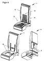
- FIG. 3 illustrates in an illustrative manner the many uses of the present invention. Additional heaters as in FIG. 4 shown are used in numerous places in the vehicle. Thus, additional heaters are installed in the dashboard or in the seat, back and neck area of vehicle seats. Also contain today's vehicles to increase comfort several blower or heating modules. Since the present invention individually determines the temperature of the incoming air for each of the heating elements integrated in the vehicle, each heating element can operate autonomously and thus be used decentrally.
- the motor vehicle seat 11 has a seat cushion part 12 and a backrest 13 in the usual form.
- Both the seat cushion part 12, as well as the backrest 13 consist essentially of a support body particularly advantageous from rigid foam, such as polyurethane, but also as a spring core seat, in which the required mounting rails and frames are integrated.
- a knitted fabric 14 is glued on the outer cover 15, such as velor or leather, is located.
- air flow channels 16 provided in the example shown, which open into a chamber and are open on their entire length to the knitted fabric 14 out.
- additional heaters 6 are placed in openings provided for this purpose. Through the air ducts 16, the heated air from the additional heaters is forwarded to the vehicle occupants.
- the auxiliary heater of the present invention can be used in the same way in seats having an air duct (or more) for heating the neck region of the vehicle occupant. In this case, for example, not just one but also three additional heaters are used, each of which supply the seat, back or neck area of the seat occupant with warm air.
- each heating element 4 When using multiple booster heaters in a vehicle, however, it is not necessary to provide each heating element 4 with an electronic control 7. To reduce the cost, the vehicle may be provided with only a single electronic control associated with the individual heating elements, e.g. is connected via a bus or analog, and adjusts the heating power to be applied by the respective heating element individually.
- each individual heating element is connected to a separate fan 8.
- a plurality of heating elements may be connected to a single fan 8 which supplies the individual heating elements with air.
- the additional heater according to the invention can be arranged, for example, in air ducts that lead air from a central fan to the rear of the vehicle arranged outlets. An individual blower is not required in such cases.
- a vehicle seat may have only one or more air passages connected to an external blower and in which one or more booster heaters are provided according to the present invention.
- the parameters of the cold air flow supplied to the heater can be provided, for example, by the central air conditioning system.
- the heating power to be expended is significantly dependent on the cold air temperature of the air flowing in the heating element 4.
- the heat output can be determined by means of different methods, for example by means of mathematical equations which contain the cold air temperature as a control variable. This mathematical computational effort can be avoided when using characteristic curves or maps.
- characteristic curves are determined which determine the dependence of the heating power from the cold air temperature, and allow the operation in each case an optimal heating power setting.
- Both methods of determination can also be combined to improve the temperature determination.
- partial aspects of the mathematical calculation such as the temperature dependence of parameters, can be easily represented by maps. This considerably simplifies the calculation effort, since there are often no exact formulas for the properties of the parameters.
- the use of characteristics has the advantage that they can be updated if necessary.
- the control of the heating power can be adapted to changing characteristics of the additional heating, e.g. their possible pollution, adapt.
- control unit 2 and / or the temperature determination unit 3 may include a memory unit (not shown) containing control programs, function routines or characteristics defining the temperature determination and control of the heating element.
- a processor is preferably provided in one or both units, which executes the programs stored in the memory unit.
- the data stored in the storage units can be easily updated by the terminals 5a and 5b.
- the target hot air temperature and the air mass flow are fixed, so that the heating power to be provided depends only on the possibly variable cold air temperature.
- an efficiency factor ⁇ can additionally be taken into account.
- the cold air temperature needed to calculate the heating power can be determined in several ways. The easiest way to realize this by means of a temperature sensor between fan and heating element, which measures the temperature of the air flowing against the heating element. However, the use of such a sensor is not necessary because a variety of in-vehicle devices measure temperatures in or on the vehicle that can be used to determine the cold air temperature. For example, an in-vehicle air conditioning system measures a temperature that allows conclusions to be drawn about the temperature inside the vehicle. If the blower that supplies the additional heating system with air, eg during circulation operation, sucks in the air from the interior of the vehicle, then the temperature measured by the air conditioning system forms a good value for the cold air temperature.
- the air supply is operated in a continuous flow, the air is not sucked out of the vehicle but fresh air from the outside.
- the outside temperature measured by a vehicle mounted temperature sensor is a good measure of cold air temperature.
- the present invention uses an ambient temperature T environment measured by a temperature sensor located in or on the vehicle to determine the cold air temperature.
- the correction factors may also be time-dependent. Such a time dependence occurs, for example, if the ambient temperature is measured, for example, on the dashboard or on the center console, which are heated very quickly to a certain temperature, while the air is sucked, for example, near the bottom of the interior and only slowly to the temperature heated the console.
- the cold air temperature has only been determined from a temperature measured in or on the vehicle.
- the determination of the cold air temperature can be improved by using a plurality of temperatures.
- weighting factors or correlation factors are used which express the influence of the individual temperatures on the cold air temperature.
- the sum of the factors 1 results.
- These correlation factors can be constant both in time and in time. This allows an evaluation of the quality of the values provided by the vehicle.
- a correlation / weighting of a plurality of temperature values is shown below by way of example by means of a combination between a measured indoor and outdoor temperature.
- T Cold F Outside t ⁇ T Outside + F Inside t ⁇ T Inside ,
- the temperature determination unit 3 preferably stores characteristics which detect the dependencies of the individual factors. These characteristics or maps are determined empirically by measurement series. Thus, individual values can be determined for each vehicle type, whereby the control of the heating power can be optimally adapted to the vehicle.
- the heat output to be provided depends not only on the cold air temperature but also on the desired hot air temperature, which is constant in the simplest embodiment of the auxiliary heater 1.
- additional heating often does not suffice for the comfort requirement of a vehicle occupant.
- the additional heating control unit additionally takes into account, according to a further embodiment of the present invention, a temperature setpoint, which is determined from a value received via terminal 5a from an external input device.
- the temperature setpoint can be determined in various ways from the received signal.
- the value transmitted by the external device corresponds to the exact temperature value entered by the user.
- the temperature of the vehicle occupant can be continuously varied or adjusted.
- the target temperature is not precisely predetermined by the vehicle occupant, but merely a comfort level is selected which corresponds to a specific temperature value. In this case, it may not be the exact temperature value that is passed on to the control unit, but only a value that reflects the selected comfort level.
- a table can also be stored in the memory of the control unit, in which the individual target temperatures are listed as a function of the received signal.
- the heating power In addition to the cold air temperature and the target hot air temperature and the air mass flow flowing through the heating element, important for the heating power to be provided. In the simplest embodiment of the additional heating of this air flow is chosen to be constant. However, such an embodiment often does not meet the comfort needs of the vehicle occupants.
- control unit 2 of the auxiliary heater 1 takes into account an air mass flow which is determined from a value received via an input 5a from a terminal 5.
- the mass air flow is not accurately selected by the vehicle occupant, but merely set a comfort level that corresponds to a certain air mass flow.
- a comfort level that corresponds to a certain air mass flow.
- This value can e.g. come from the blower 8 or directly from a user-operable control unit itself.
- the air mass flow flowing through the additional heater 1 is determined. If the exact value is transmitted, it can be used directly in formula (i).
- the air mass flow can also be determined from the transmitted value by means of a table stored in the memory of the control unit in which the dependence of the air mass flow on the received signal is described become.
- the desired hot air temperature and the air mass flow parameters such as For example, to consider the vehicle speed or the outside temperature. These are of great importance for open vehicles such as convertibles or open windows or sunroofs.
- the airstream leads to a cooling of the air flowing from the additional heating air.
- the air reaching the passenger no longer has the desired temperature.
- the present invention varies according to a preferred embodiment, the desired hot air temperature in dependence on the speed of the vehicle. This variation is chosen so that the cooling caused by the wind is compensated.
- the target hot air temperature is preferably chosen so that it increases with increasing vehicle speed.
- the desired hot air temperature is reduced with decreasing vehicle speed. In the simplest way, this can be implemented by requiring a linear dependence of the target hot air temperature on the vehicle speed, but a non-linear dependence of the target hot air temperature on the vehicle speed can also be used. In addition to a continuous variation of the target hot air temperature as a function of the vehicle speed, this can also be done gradually.
- corresponding temperature corrections can be assigned to the respective vehicle speeds for the variation of the desired hot air temperature, for example by using a mathematical function "which indicates how much a preselected desired hot air temperature is to be increased or decreased
- Table 1 shows an exemplary map in which target hot air temperatures for three comfort levels and four different speeds are plotted: the value of the setpoint hot air temperature when the vehicle is at a standstill can be regarded as a kind of basic value, which is adjusted as a function of the vehicle speed.
- Table 1 Dependence of the target hot air temperature on the vehicle speed and the comfort level.
- the desired hot air temperature is additionally adapted to the outside temperature, so that at lower outside temperature automatically a higher target hot air temperature is selected.
- the outside temperature-dependent desired hot air temperature can be specified by an absolute temperature value.
- relative temperature values may also be used which should be corrected as a predetermined target hot air temperature as a function of the outside temperature. It should be noted that the various temperature corrections, for example, to adjust the target hot air temperature At the vehicle speed or the outside temperature, can be combined with each other, so that the target hot air temperature can be adapted to different parameters simultaneously.
- the present invention reduces the strength of the air mass flow in dependence on a standstill signal indicating the stoppage of the vehicle.
- the standstill signal is generated only at the exact stoppage of the vehicle. Rather, the standstill signal can also indicate that the vehicle speed is below a certain limit and thus the early stopping of the vehicle is to be expected.
- the air mass flow is preferably varied as a function of the speed of the vehicle.
- this variation is chosen so that the changes caused by the wind are compensated by varying the speed of the fan, so that with increasing vehicle speed of the air mass flow increases, while it is reduced with decreasing vehicle speed.
- the air mass flow is adapted to the vehicle speed during the entire journey, can be dispensed in this case to a signal indicating the stoppage of the vehicle.
- the adjustment of the air mass flow can be carried out by the control unit 2, which additionally automatically adjusts the heating power to be applied to the changed air mass flow.
- the control unit 2 it is also possible that another control unit in the vehicle, the fan speed varies depending on the vehicle speed and the control unit 2 automatically adjusts the heating power according to this adjustment.
- the variation of the speed can be done in different ways.
- the variation can be predetermined, for example, by using a continuous linear or non-linear mathematical function, which assigns speeds corresponding to the vehicle speeds from which the air mass flow can be calculated.
- the air mass flow can be gradually adjusted to the vehicle speed instead of a continuous variation.
- a map can be stored in the control unit, which contains speeds as a function of the vehicle speed and the comfort level. Table 2 shows an exemplary map in which different speeds are entered for three comfort levels and four different speeds. Table 2: Dependence of the fan speed on the vehicle speed and the comfort level.
- correction values instead of absolute fan speed values, which indicate how much a preselected fan speed is varied as a function of the speed.
- the desired hot air temperature and the speed of the fan is determined decisively by the speed of the vehicle.
- the determination of vehicle speed can be done in several ways.
- a speed signal can be supplied to the control unit 2.
- the speed can also be determined from the wheel or transmission speed or from the ABS.
- the control unit 2 may receive a signal indicating the exact speed value, or a value, e.g. indicates a speed from which the vehicle speed is derived by means of a stored in the control unit 2 functions or tables.
- an explicit determination of the speed from speed-dependent parameters, such as the wheel speed is not necessary. So it is also possible to use functions or maps that describe the dependence of the heat output to be applied directly from the parameters.
- the surface temperature of the heating elements increases rapidly as the air mass to be heated (e.g., reduced fan speed) is reduced. This leads to a for the Vehicle occupants unwanted, unpleasant "over-temperature effect”. This is to be avoided in particular when used as headspace heating.
- the unavoidable thermal inertia of the heating element usually causes a delay in the temperature change of the heated air.
- the heating power applied by the heating element 4 controlled so that it initially deviates from the calculated setpoint for a certain time.
- FIG. 5 shows an exemplary time profile of the heating power applied by a heating element 3 with an increase in the air flow rate and an associated increase in the heating power to be applied.
- the heating element is briefly supplied with a higher heat energy than the current vehicle speed is associated with a positive load change, such as an increase in comfort level.
- a higher heat output is achieved that the air heats up as desired despite the inertia.
- control unit 2 is configured so that, for a negative load change, e.g. a lowering of the comfort level, a lower heating energy is selected than is provided for the respective vehicle speed.
- a negative load change e.g. a lowering of the comfort level
- a lower heating energy is selected than is provided for the respective vehicle speed.
- the heating elements or the elements are controlled via a pulse-width modulation (PWM).
- PWM pulse-width modulation
- the heating power is set via the duty cycle.
- this duty cycle is either increased for a short time (in the case of a positive load change when switching to a higher comfort level) or decreased (in the case of a negative load change, ie when switching to a lower comfort level).
- the exact control of the temporal increase or decrease of the duty ratio is theoretically difficult to detect. Therefore, it is preferably determined empirically depending on the requirement vehicle-dependent.
- a characteristic map or a plurality of characteristic maps is stored in the memory of the control unit or the temperature determination unit, which indicate depending on the previously described parameters, such as the cold air temperature, the vehicle speed and the like, which heat output from the heating element So that the exiting the heating air has a certain target hot air temperature.
- measurement series are carried out for a large number of output parameters, such as the cold air temperature, the size of the air mass flow, the opening state of the windows or the hood, desired hot air temperature and the like, in order to experimentally determine the heat output which is the heating element to heat the air to be heated to a target temperature. Due to the individually determined characteristics for a vehicle or vehicle type, the control of the additional heating can be individually and accurately adapted to a vehicle or a vehicle type.
- the determination of the maps can also be separated into different sections.
- the manufacturer of auxiliary heater determine their properties in the factory experimentally and store in a first map
- the automaker determines a second map that captures the influences of the vehicle.
- control allows a simple modification of the control unit or the temperature determination unit by means of maps, since the data stored in these modules / storage units can be easily updated via terminals 5a and 5b.
- control unit performs an error detection.
- the control unit 2 uses a small value for the air mass flow.
- the heating power can be switched back by a (comfort) level to compensate for the reduced air mass flow. If the plausibility is still not given with the reduction of the air mass flow value or with the associated reduction in heating power, the considered value of the air mass flow is further reduced. This is possible until the heating module is switched off completely.
- PTC heating elements have a temperature-dependent ohmic resistance, which increases with increasing temperature of the heating element. Therefore, the current flowing through the heating element decreases at a constant voltage as the heating element heats up. If air flows through the radiator elements connected to the heating element, the air extracts heat energy from the heating element; the heating element is quasi cooled. As a result, the electrical resistance of the heating element remains constant, although heating power will be delivered to the air to be heated. Therefore, in the case of continuous air flow through the PTC element, the current flowing through the element must be above a value to be set. In the event of a disturbed airflow, e.g. in the event of a blockage or a faulty fan, the current value drops below the specified limit (PTC effect). This leads to a shutdown of the heating element.
- PTC effect the specified limit
- the heating element Even if it is switched off passively by the above-described PTC effect, the heating element, the outgoing warm air before switching off under Circumstances are heated to temperatures that are perceived by the vehicle occupants as unpleasant or disturbing. To avoid this, preferably the current across the heating element is measured. If the value of the signal falls below a predetermined value, the heating element 4 is switched off by the control unit.
- the auxiliary heater 1 has a separate temperature-determining unit 3 and control unit 2, this particular embodiment for an auxiliary heater 1 according to the present invention is not mandatory.
- the functions may also be integrated into a single component, which includes, for example, a memory and a processor which uses the control programs stored in the memory for determining the temperature and control of the heating element control routines.
- control unit 2 can be sent to determine the influence of the wind a signal that contains information about the top status or the opening degree of the window.
- control unit 2 can detect by means of this signal whether the top or sunroof is closed or open or which windows are opened and how far they are open.
- the present invention provides an electric booster heater that safely avoids temperature overshoot in the heated air.
- the temperature of the air flowing into the heating air is determined and preferably converted depending on the desired outlet temperature in a heating power for controlling the heating elements.
- This conversion preferably takes place via a stored characteristic curve field, which in a simple way takes into account the consideration of a plurality of vehicle parameters, such as the speed of the vehicle, of the vehicle Hoods, etc. allows.
- the temperature of the incoming air can be derived based on already existing in the vehicle temperature values.
- a user-friendly electric heating can be realized very easily, which can preferably be used decentrally in the vehicle, for example in the motor vehicle seat or in the vehicle fund. Even with dynamically changing operating conditions of the motor vehicle temperature fluctuations in the heated air can be safely and easily avoided.
Abstract
Description
Die Erfindung bezieht sich auf eine elektrische Zusatzheizung für ein Kraftfahrzeug. Insbesondere betrifft die Erfindung eine Zusatzheizung, die neben einem Heizelement auch eine Steuereinheit zur Einstellung der von dem Heizelement aufzubringenden Heizleistung aufweist.The invention relates to an electric auxiliary heater for a motor vehicle. In particular, the invention relates to an additional heater, which also has a control unit for adjusting the heating power to be applied by the heating element in addition to a heating element.
Um den Komfort in einem Kraftfahrzeug zu erhöhen, werden bereits seit geraumer Zeit Heizungen eingesetzt. Bei diesen Heizungen wird die von einem Gebläse angesaugte bzw. ausgestoßene Luft durch die Abwärme des Motors oder unter Verwendung zusätzlicher Heizmodule erwärmt und in den Innenraum des Kraftfahrzeugs geblasen. Die Heizleistung solcher in Armaturen, Sitzen oder anderen Teilen des Fahrzeugs angebrachter Heizungen wird in der Regel manuell vom Benutzer bestimmt, jedoch hat der Benutzer nur geringen Einfluss auf die genaue Temperatur der ausströmenden Luft.In order to increase the comfort in a motor vehicle, heaters have been used for some time. In these heaters, the air sucked by a blower is heated by the waste heat of the engine or by using additional heating modules and blown into the interior of the vehicle. The heating power of such mounted in fittings, seats or other parts of the vehicle heaters is usually determined manually by the user, but the user has little influence on the exact temperature of the outflowing air.
Da im allgemeinen lediglich die Heizleistung oder eine Heizleistungsstufe vorgegeben werden kann, ist das Erreichen einer gewünschten Raumtemperatur im Fahrzeuginneren teilweise ein schwierigeres Unterfangen. Zu Beginn des Heizens ist die Heizleistung z.B. aufgrund eines kalten Motors sehr gering. Deshalb wird vom Benutzer zunächst eine sehr hohe Heizleistung gewählt oder elektrische Zusatzheizungen verwendet. Erhöht sich jedoch die Temperatur des Motors, so ist die in den Innenraum geblasene Luft viel heißer als vom Fahrgast erwünscht, so dass dieser die Heizleistung der Zusatzheizung oder die gewählte Heizstufe reduziert. Meistens wird die Heizleistung jedoch so stark reduziert, dass die Temperatur im Fahrzeuginneren wieder zu stark absinkt, und die Heizleistung wieder erhöht werden muss.Since in general only the heating power or a heating power level can be specified, reaching a desired room temperature in the vehicle interior is sometimes a more difficult task. At the beginning of heating, the heating power is e.g. very low due to a cold engine. Therefore, the user first selects a very high heat output or uses electrical booster heaters. However, as the temperature of the engine increases, the air blown into the interior is much hotter than desired by the passenger, reducing the auxiliary heat output or the selected heating level. Mostly, however, the heating power is reduced so much that the temperature inside the vehicle sinks again too much, and the heating power must be increased again.
Wie aus dem obigen Beispiel ersichtlich ist, kann das Erreichen einer angestrebten Innenraumtemperatur unter Umständen ein sehr zeitraubender Prozess sein. Dies wird zusätzlich noch dadurch verstärkt, dass die erwärmte Luft durch ein Gebläse in den Innenraum geblasen wird. Neben der gewählten Heizleistung wirkt sich auch die Stärke des Gebläses auf die Temperatur der in den Innenraum strömenden Luft aus. Da Benutzer die Stärke des Gebläses während der Fahrt oft variieren, kommt es durch die damit verbundene Veränderung der durch die Heizung strömenden Luftmenge zu weiteren Temperaturschwankungen. Dadurch wird das Erreichen einer Zieltemperatur zusätzlich erschwert.As can be seen from the above example, the achievement of a desired interior temperature may be a very time-consuming process. This is additionally reinforced by the fact that the heated air is blown by a blower into the interior. In addition to the selected heating power, the strength of the fan also affects the temperature of the air flowing into the interior. Since users often vary the size of the blower while driving, the associated change in the amount of air flowing through the heater causes further temperature fluctuations. This makes it even more difficult to reach a target temperature.
Aus
Ein weiterer Nachteil der in
Aufgabe der vorliegenden Erfindung ist es, eine elektrische Zusatzheizung mit einfacherer Temperatursteuerung und höherer Benutzerfreundlichkeit anzugeben.Object of the present invention is to provide an electric booster heater with simpler temperature control and ease of use.
Diese Aufgabe wird erfindungsgemäß durch die Merkmale der unabhängigen Ansprüche gelöst. Vorteilhafte Ausführungsformen mit zweckmäßigen Weiterbildungen der Erfindung sind in den Unteransprüchen angegeben.This object is achieved by the features of the independent claims. Advantageous embodiments with expedient developments of the invention are specified in the subclaims.
Es ist der besondere Ansatz der vorliegenden Erfindung, anstelle der Warmlufttemperatur die Temperatur der zuströmenden Kaltluft zu erfassen. Erfindungsgemäß weist die elektrische Zusatzheizung wenigstens ein PTC-Heizelement, welches die durch die Zusatzheizung strömende Luft erwärmt, und eine Steuereinheit, welche die vom Heizelement abgegebene Heizleistung einstellt, auf. Um die Heizleistung an die Temperatur der zu erwärmenden kalten Luft anzupassen, ermittelt eine Temperaturbestimmungseinheit diese Kaltlufttemperatur. Basierend auf der ermittelten Kaltlufttemperatur bestimmt die Steuereinheit die vom Heizelement zu erbringende Heizleistung.It is the particular approach of the present invention to detect the temperature of the incoming cold air instead of the hot air temperature. According to the invention the electric auxiliary heater has at least one PTC heating element, which heats the air flowing through the additional heating air, and a control unit which adjusts the heating power output by the heating element. In order to adapt the heating power to the temperature of the cold air to be heated, a temperature determination unit determines this cold air temperature. Based on the determined cold air temperature, the control unit determines the heat output to be provided by the heating element.
Durch die Ermittlung der Temperatur der anströmenden zu erwärmenden Luft, im folgenden als "Kaltlufttemperatur" bezeichnet, kann die aufzubringende Heizleistung exakt an die Eigenschaften der anströmenden Luft angepasst werden. Auf diese Weise können drohende Temperaturschwankungen bei dynamischen Betriebszuständen besser erkannt und rechtzeitig durch Anpassung der Heizleistung kompensiert werden. Ist z.B. die zu erwärmende Luft sehr kalt, so ist zu deren Erwärmung eine höhere Heizleistung notwendig, während eine höhere Lufttemperatur eine geringer Heizleistung zur Erwärmung benötigt. Da die Temperatur der aus der Zusatzheizung strömenden Luft von der Kaltlufttemperatur und der Heizleistung abhängt, lässt sich diese Temperatur sehr viel besser kontrollieren, so dass Schwankungen in der Ausgangstemperatur vermieden werden können.By determining the temperature of the incoming air to be heated, hereinafter referred to as "cold air temperature", the heating power to be applied can be adapted exactly to the properties of the inflowing air. In this way, impending temperature fluctuations can be better recognized under dynamic operating conditions and compensated in good time by adjusting the heating power. Is e.g. the air to be heated is very cold, a higher heating power is necessary to heat them, while a higher air temperature requires less heat to heat. Since the temperature of the air flowing from the auxiliary heater depends on the cold air temperature and the heating power, this temperature can be controlled much better, so that fluctuations in the starting temperature can be avoided.
Vorzugsweise bestimmt die Temperaturbestimmungseinheit die Kaltlufttemperatur unter Verwendung wenigstens eines gemessenen Temperaturwerts. Dabei kann zusätzlich vorzugsweise mindestens ein Korrekturfaktor verwendet werden. Durch die Verwendung eines Korrekturfaktors ist es nicht nötig, die Temperatur der zu erwärmenden Luft mittels eines im Luftkanal vor dem Heizelement angebrachten Sensors zu messen. Vielmehr lässt sich diese Temperatur aus Temperaturwerten bestimmen, die von anderen Bauteilen eines Fahrzeugs, wie z.B. der Klimaanlage, zur Verfügung gestellt werden. So kann im Umwälzmodus der Lüftung/Heizung die Temperatur der angesaugten Luft leicht aus der Innenraumtemperatur des Fahrzeugs bestimmt werden, während im Durchlaufbetrieb, bei dem frische Außenluft in das Fahrzeug strömt, die Außentemperatur am Fahrzeug ein guter Wert für die Kaltlufttemperatur darstellt.Preferably, the temperature determination unit determines the cold air temperature using at least one measured temperature value. In addition, preferably at least one correction factor can be used. By using a correction factor, it is not necessary to measure the temperature of the air to be heated by means of a sensor mounted in the air duct in front of the heating element. Rather, this temperature can be determined from temperature values that are provided by other components of a vehicle, such as the air conditioning. Thus, in the circulation mode of the ventilation / heating, the temperature of the intake air can be easily determined from the interior temperature of the vehicle, while in continuous operation, in which fresh outside air flows into the vehicle, the outside temperature on the vehicle is a good value for the cold air temperature.
Um die Kaltlufttemperatur aus einem im Fahrzeug an anderer Stelle erfassten Temperaturwert zu bestimmen, werden vorzugsweise Korrekturfaktoren, die den Temperaturunterschied zwischen der gemessenen Temperatur und der tatsächlichen Kaltlufttemperatur ausgleichen, verwendet. Oft ist dieser Temperaturunterschied während des Betriebs des Fahrzeugs nicht konstant. Um dieser zeitlichen Variation Rechnung zu tragen, verwendet die Temperaturbestimmungseinheit in einer weiter vorteilhaften Ausführungsform Korrekturfaktoren, welche die zeitliche Variation der Kaltlufttemperatur gegenüber dem gemessenen Temperaturwert korrigieren.In order to determine the cold air temperature from a temperature value detected elsewhere in the vehicle, preferably correction factors which compensate for the temperature difference between the measured temperature and the actual cold air temperature are used. Often this temperature difference is not constant during operation of the vehicle. In order to take account of this temporal variation, the temperature determination unit uses in a further advantageous embodiment correction factors which correct the temporal variation of the cold air temperature with respect to the measured temperature value.
Da bei einem Fahrzeug mit offenen Verdeck bzw. geöffneten Fenstern sich die Außentemperatur maßgebend auf die Kaltlufttemperatur der zu erwärmenden Luft auswirkt, erfolgt die Ermittlung der Kaltlufttemperatur vorzugsweise aus einer gewichteten Kombination einer Fahrzeuginnenraum- und der Fahrzeugaußenraumtemperatur.Since in a vehicle with open top or open windows, the outside temperature has a significant effect on the cold air temperature of the air to be heated, the determination of the cold air temperature is preferably made of a weighted combination of vehicle interior and vehicle exterior temperature.
Alternativ verwendet die Temperaturbestimmungseinheit der vorliegenden Erfindung einen im Luftansaugtrakt zwischen einem Gebläse und dem Heizelement angeordneten Temperatursensor zum Messen der Kaltlufttemperatur. Da die Kaltlufttemperatur oft nicht direkt vor dem Heizelement gemessen wird, kann sich die Kaltlufttemperatur nach der Temperaturmessung unter Umständen geringfügig ändern bevor die Luft erwärmt wird. Deshalb wird vorzugsweise zusätzlich ein Korrekturfaktor verwendet, der Abweichungen vom gemessenen Wert berücksichtigt.Alternatively, the temperature determination unit of the present invention uses a temperature sensor arranged in the air intake tract between a fan and the heater for measuring the cold air temperature. Since the cold air temperature is often not measured directly in front of the heating element, the cold air temperature may change slightly after the temperature measurement before the air is heated. Therefore, a correction factor which takes into account deviations from the measured value is preferably additionally used.
Um die Heizleistung an die Wünsche des Nutzers optimal anzupassen, berücksichtigt die Steuereinheit zusätzlich vorzugsweise eine Soll-Warmlufttemperatur, welche fest vorgegeben oder vom Nutzer frei wählbar ist. Die Wahl der Heizleistung kann dabei in Stufen oder kontinuierlich erfolgen. Vorzugsweise ist der Wert der Soll-Warmlufttemperatur davon abhängig, ob das Fahrzeug geschlossen oder offen bewegt wird. So lässt sich die Soll-Warmlufttemperatur in einfacher Weise an dynamische Fahreinflüsse, die durch ein offenes Verdeck oder ein offenes Fenster verursacht werden, anpassen. Vorzugsweise wird die Soll-Warmlufttemperatur zusätzlich in Abhängigkeit von der Außentemperatur eingestellt, da diese bei offenem Verdeck die Temperatur im inneren des Fahrzeugs maßgeblich beeinflusst. Dies ist vor allem bei der Verwendung der Zusatzheizung im Nackenbereich eines Fahrzeuginsassen von Vorteil. Um die Einflüsse des Fahrtwindes, z.B. durch Verwirbelungen, zusätzlich zu berücksichtigen, stellt die Steuereinheit die Soll-Warmlufttemperatur vorzugsweise in Abhängigkeit von der Fahrzeuggeschwindigkeit ein. Dabei steigt vorzugsweise die Soll-Warmlufttemperatur kontinuierlich oder stufenweise bei wachsender Fahrzeuggeschwindigkeit, während sie bei abnehmender Fahrzeuggeschwindigkeit wieder reduziert wird.In order to optimally adapt the heating power to the wishes of the user, the control unit additionally preferably takes into account a desired hot air temperature, which is fixedly preset or freely selectable by the user. The choice of heating power can be done in stages or continuously. Preferably, the value of the target hot air temperature depends on whether the vehicle is being closed or being moved open. Thus, the target hot air temperature can be easily adapted to dynamic driving influences caused by an open top or an open window. Preferably, the target hot air temperature is additionally set as a function of the outside temperature, since this significantly affects the temperature in the interior of the vehicle with the top down. This is above all when using the additional heater in the neck area of a vehicle occupant advantage. In order to additionally take into account the effects of the wind, for example due to turbulences, the control unit preferably sets the desired hot air temperature as a function of the vehicle speed. In this case, preferably, the target hot air temperature increases continuously or stepwise with increasing vehicle speed, while it is reduced again as the vehicle speed decreases.
Neben der Kaltlufttemperatur und der Soll-Warmlufttemperatur hat auch der Luftmassenstrom, also der Luftdurchsatz durch das Heizelement, Einfluss auf die zu erbringende Heizleistung. Insbesondere benötigt ein höherer Luftmassenstrom eine größere Heizleistung, um auf eine vorgegebene Solltemperatur aufgeheizt zu werden. Um diesem Sachverhalt Rechnung zu tragen, berücksichtigt die Steuereinheit zur Einstellung der zu erbringenden Heizleistung vorzugsweise zusätzlich den durch das Heizelement strömenden Luftmassenstrom. Die Wahl des Luftmassenstroms kann dabei in Stufen oder kontinuierlich erfolgen. Vorzugsweise wird der Wert des Luftmassenstroms automatisch eingestellt je nachdem, ob das Fahrzeug geschlossen oder offen verwendet wird. So lässt sich der Luftmassenstrom in einfacher Weise an Einflüsse eines offenen Verdecks oder Fensters anpassen. Dies ist vor allem bei der Verwendung der Zusatzheizung im Nackenbereich eines Fahrzeuginsassen von Vorteil.In addition to the cold air temperature and the target hot air temperature, the air mass flow, ie the air flow through the heating element, has an influence on the heating power to be provided. In particular, a higher air mass flow requires a greater heating power in order to be heated to a predetermined setpoint temperature. In order to take this fact into account, the control unit preferably also takes into account the air mass flow passing through the heating element in order to set the heating power to be provided. The choice of air mass flow can be done in stages or continuously. Preferably, the value of the mass air flow is automatically adjusted depending on whether the vehicle is used closed or open. Thus, the air mass flow can be easily adapted to influences of an open top or window. This is particularly advantageous when using the additional heater in the neck area of a vehicle occupant.
Bei Fahrten mit offenem Verdeck erzeugt der Fahrtwind Verwirbelungen im Fahrzeuginneren, die ein Fahrzeuginsasse im Allgemeinen durch Erhöhung der Gebläseleistung kompensiert. Wird das Fahrzeug jedoch abrupt gestoppt, so ist die ausgewählte Gebläseleistung zu hoch, so dass es beim Fahrzeuginsassen zu einem unangenehmen und ungewollten Übertemperierungseffekt kommen kann. Um dies zu Vermeiden, wird basierend auf einem Signal, das auf den Stillstand des Fahrzeugs hinweist, der Luftmassenstrom vorzugsweise auf einen vorwählbaren Wert eingestellt.When driving with the top down, the wind creates turbulence in the vehicle interior, which generally compensates for a vehicle occupant by increasing the blower output. However, if the vehicle is stopped abruptly, the selected blower output is too high, so that the vehicle occupant may experience an unpleasant and undesired over-tempering effect. To avoid this, based on a signal indicative of the stoppage of the vehicle, the air mass flow is preferably set to a preselectable value.
Um zusätzlich die Einflüsse des Fahrtwindes auch während der Fahrt zu berücksichtigen, stellt die Steuereinheit den Luftmassenstrom vorzugsweise in Abhängigkeit von der Fahrzeuggeschwindigkeit ein. Vorzugsweise erhöht sich der Luftmassenstrom bei wachsender Fahrzeuggeschwindigkeit, während er bei sinkender Fahrzeuggeschwindigkeit wieder reduziert wird.In order additionally to take into account the influences of the airstream while driving, the control unit adjusts the air mass flow preferably as a function of the vehicle speed. Preferably, the air mass flow increases with increasing vehicle speed, while it is reduced again with decreasing vehicle speed.
Ändert sich während des Betriebs der Zusatzheizung die Soll-Warmlufttemperatur und/oder der Luftmassenstrom, so ist eine Anpassung der zu erbringenden Heizleistung nötig. Aufgrund der Trägheit der PTC-Heizelemente wird, z.B. bei einer Erhöhung der Soll-Warmlufttemperatur, die zur Erwärmung der auf den neuen gewünschten Temperatursollwert der ausströmenden Luft ermittelte Heizleistung nicht sofort in vollem Umfang an die zu erwärmende Luft abgegeben. Um diesen Trägheitseffekt auszugleichen, überkompensiert (erhöht bzw. erniedrigt) die Steuereinheit vorzugsweise die zu erbringende Heizleistung bei Änderung der Soll-Warmlufttemperatur und/oder des Luftmassenstroms für eine vorgegebene Zeitspanne nach dem Zeitpunkt der Änderung, d.h. für die Heizleistung wird je nach Änderung der Soll-Warmlufttemperatur/des Luftstroms während der vorgegebenen Zeitspanne ein Wert gewählt, der höher bzw. niedriger ist als der Wert, der für die Soll-Warmlufttemperatur/den Luftstrom eigentlich vorgesehen ist. Die Überkompensation der Heizleistungsänderung wird vorzugsweise über eine vorgegebene (oder beispielsweise von der Änderungshöhe abhängigen) Zeitspanne durchgeführt. Dabei kann die Höhe der Überkompensation zum Ende der Zeitspanne hin abnehmen, um einen kontinuierlichen Übergang zu erreichen.If the setpoint hot air temperature and / or the air mass flow changes during the operation of the additional heater, an adaptation of the heating power to be provided is necessary. Due to the inertia of the PTC heating elements, e.g. at an increase in the target hot air temperature, which is not immediately released to the heated air to heat the determined to the new desired temperature setpoint of the effluent air heating power. In order to compensate for this inertia effect, the control unit preferably overcompensates (increases or decreases) the heating power to be provided when the desired hot air temperature and / or air mass flow is changed for a predetermined time after the time of the change, i. for the heating power is selected depending on the change in the target hot air temperature / air flow during the predetermined period, a value which is higher or lower than the value that is actually provided for the desired hot air temperature / air flow. The overcompensation of the heating power change is preferably carried out over a predetermined (or, for example, dependent on the amount of change) period of time. The amount of overcompensation may decrease towards the end of the time to achieve a continuous transition.
Um unerwünschte Folgen einer Blockade des Luftauslasses bzw. -Einlasses oder bei Ausfall des die Heizung mit Luft versorgenden Gebläses zu verhindern, berücksichtigt die Steuereinheit vorzugsweise die am Gebläse anliegende Spannung. Ein Absinken der am Gebläse anliegenden Spannung ist ein deutliches Indiz für eine Blockade des Luftauslasses bzw. -Einlasses. Deshalb reduziert die Steuereinheit den durch die Zusatzheizung strömenden Luftmassenstrom, falls die Spannung einen Grenzwert unterschreitet.In order to prevent unwanted consequences of blockage of the air outlet or in case of failure of the heater supplying the heater with air, the control unit preferably takes into account the voltage applied to the fan. A decrease in the voltage applied to the fan is a clear indication of a blockage of the air outlet or inlet. Therefore, the control unit reduces the air mass flow flowing through the auxiliary heater if the voltage falls below a threshold value.
In ähnlicher Weise zeigt der über das Heizelement gemessene Strom ein Problem im Luftstrom an, da bei einem gestörten Luftstrom der Stromwert absinkt (PTC-Effekt). Deshalb schaltet die Steuereinheit vorzugsweise das Heizelement ab, falls der über das Heizelement gemessene Strom eine vorgegebene Grenze unterschreitet.Similarly, the current measured across the heater indicates a problem in the airflow, as the current value decreases with a faulty airflow (PTC effect). Therefore, the control unit preferably switches off the heating element if the current measured via the heating element falls below a predetermined limit.
Da die zur Bestimmung der aufzubringenden Heizleistung nötigen Parameter, wie die Heizeigenschaften des Heizelements oder die Einflüsse Fahrzeugs, oft nicht theoretisch bekannt sind, verwendet die Zusatzheizung vorzugsweise ein Kennfeld, das die Eigenschaften dieser Parameter beschreibt. Dabei kann die Steuerung der Zusatzheizung durch Kombination mathematischer Formeln und des Kennfeldes erfolgen. Auch kann die Steuereinheit die Einstellung der Heizleistung vollständig mittels Kennfelder durchführen.Since the parameters necessary for determining the heat output to be applied, such as the heating properties of the heating element or the influences of the vehicle, are often not theoretically known, the additional heater preferably uses a characteristic map which describes the properties of these parameters. The control of the additional heating can be done by combining mathematical formulas and the map. Also, the control unit can perform the adjustment of the heating power completely using maps.
Um den Aufwand zur Verkabelung der Zusatzheizung mit anderen Bauteilen eines Fahrzeugs zu verringen, werden die von den Bauteilen gelieferten Signale vorzugsweise über ein Bussystem im Kraftfahrzeug zur Verfügung gestellt.In order to reduce the cost of wiring the auxiliary heater with other components of a vehicle, the signals supplied by the components are preferably provided via a bus system in the motor vehicle available.
Mit der vorliegenden Erfindung ist eine elektrische Zusatzheizung im Kraftfahrzeug in einfacher Weise überall als autark operierende Zusatzheizung einsetzbar. Sie eignet sich daher besonders gut zur dezentralen Beheizung und kann an beliebigen Einsatzorten montiert werden, beispielsweise in Fahrzeugsitzen, im Fondbereich, im Fußraum, oder in den B- oder C-Säulen eines Kraftfahrzeugs. Vor allem die genaue Bestimmung der aufzubringenden Heizleistung ermöglicht es, die Zusatzheizung in direkter Nähe der Fahrzeuginsassen einzusetzen. Vorzugsweise ist deshalb die Zusatzheizung in einem Fahrzeugsitz vorgesehen, der den Sitz-, Rücken- oder Nackenbereich eines Insassen mit warmer Luft versorgt.With the present invention, an electric booster heater in the vehicle in a simple manner anywhere as a self-sufficient auxiliary heater can be used. It is therefore particularly well suited for decentralized heating and can be mounted at any location, for example in vehicle seats, in the rear area, in the footwell, or in the B or C pillars of a motor vehicle. Above all, the exact determination of the heating power to be applied makes it possible to use the auxiliary heater in the immediate vicinity of the vehicle occupants. Preferably, therefore, the additional heater is provided in a vehicle seat, which supplies the seat, back or neck area of an occupant with warm air.
Weitere Vorteile, Merkmale und Einzelheiten der Erfindung ergeben sich aus der nachfolgenden Beschreibung bevorzugter Ausführungsbeispiele sowie anhand der Figuren; diese zeigen in:
- Fig. 1
- einen schematischen Aufbau der elektrischen Zusatzheizung gemäß der vorliegenden Erfindung,
- Fig. 2
- ein Ablaufdiagramm, welches das Prinzip der Steuerung der elektrischen Zusatzheizung gemäß der Erfindung darstellt,
- Fig. 3
- einen Aufbau der elektrischen Zusatzheizung gemäß der vorliegenden Erfindung mit integriertem Gebläse,
- Fig. 4
- einen Fahrzeugsitz mit eingebauter Zusatzheizung und
- Fig. 5
- einen zeitlichen Verlauf der Heizleistungsaufnahme der erfindungsgemäßen Zusatzheizung bei einem Lastwechsel.
- Fig. 1
- a schematic structure of the electric auxiliary heater according to the present invention,
- Fig. 2
- a flow chart illustrating the principle of the control of the electric booster heater according to the invention,
- Fig. 3
- a structure of the electric auxiliary heater according to the present invention with integrated fan,
- Fig. 4
- a vehicle seat with built-in auxiliary heating and
- Fig. 5
- a time course of the heating power consumption of the additional heater according to the invention during a load change.
Um die Zusatzheizung 1 mit anderen Komponenten in einem Fahrzeug zu verbinden, weist die Zusatzheizung 1 Anschlüsse 5a und 5b auf. So kann z.B. die Temperaturbestimmungseinheit 3 mittels Anschluss 5b mit einem im oder am Fahrzeug befindlichen Temperatursensor verbunden werden. Auch ist es möglich, das Verhalten der Steuereinheit über Anschluss 5a zu beeinflussen. So können über diesen Anschluss beispielsweise benutzerdefinierte Vorgaben oder Signale anderer Fahrzeugkomponenten an die Steuereinheit 2 weitergegeben werden.In order to connect the
Die Verbindung der Zusatzheizung 1 mit externen Geräten des Fahrzeugs kann dabei direkt in analoger oder digitaler Weise erfolgen. In diesem Fall ist jedoch ein hoher Kabelaufwand nötig, da jedes externe Gerät einzeln mit der Zusatzheizung 1 verbunden werden muss. Um diese Problem zu umgehen, wird in Fahrzeugen vermehrt ein Bus, z.B. CAN- oder LIN-Bus, eingesetzt. Auf dem Bus werden die Signale einer Vielzahl von Geräten an andere Geräte des Fahrzeugs mittels einer einzigen Leitung weitergegeben. Durch die Anschlüsse 5a und 5b kann die Zusatzheizung 1 in einfacher Weise mit einem solchen Datenbus verbunden werden und die über den Bus erhaltenen Signale weiterverarbeiten. So kann beispielsweise die Temperaturbestimmungseinheit 3 einen Temperaturwert einer im Fahrzeug befindlichen Klimaanlage oder eines im Luftkanal angebrachten Sensors über den Bus erhalten und die Kaltlufttemperatur der das Heizelement 4 anströmenden Luft ermitteln.The connection of the
Auch ist es möglich über die Anschlüsse 5a und 5b die Steuereinheit 2 bzw. die Temperaturbestimmungseinheit 3 zu aktualisieren oder zu warten. Jedoch ist dem Fachmann klar, dass die oben beschriebene Verwendung der Anschlüsse lediglich Beispiele sind und die Anschlüsse eine Vielzahl von Möglichkeiten zur Einflussnahme auf die Zusatzheizung bieten. Auch ist es nicht nötig die Zusatzheizung mit zwei separaten Anschlüsse auszustatten. So kann die Zusatzheizung lediglich einen mit der Steuereinheit 2 verbunden Anschluss 5a aufweisen über den die Steuereinheit 2 Daten erhält. Die von der Temperaturbestimmungseinheit 3 benötigten Daten werden in diesem Fall - falls erforderlich - von der Steuereinheit 2 an die Temperaturbestimmungseinheit 3 weitergeleitet.It is also possible to update or to wait for the
Vorzugsweise wird die Kaltlufttemperatur daher basierend auf bereits im Fahrzeug erfassten Temperaturwerten bestimmt, z.B. der Innenraumtemperatur des Fahrzeugs, einer von einer Klimaanlage gemessenen Temperatur oder dergleichen. In diesem Fall sind zur Ermittlung der Kaltlufttemperatur keine zusätzlichen Temperatursensoren nötig, sondern es können ohne Zusatzkosten die bereits im Fahrzeug integrierten Geräte verwendet werden. Details einer solchen "indirekten" Erfassung der Kaltlufttemperatur werden in einem nachfolgenden Abschnitt im einzelnen dargestellt.Preferably, therefore, the cold air temperature is determined based on temperature values already detected in the vehicle, e.g. the interior temperature of the vehicle, a temperature measured by an air conditioner, or the like. In this case, no additional temperature sensors are needed to determine the cold air temperature, but the devices already integrated in the vehicle can be used at no extra cost. Details of such "indirect" cold air temperature sensing are presented in detail in a subsequent section.
Basierend auf der so ermittelten Kaltlufttemperatur wird in Schritt S2 die vom Heizelement 4 aufzubringende Heizleistung bestimmt. Diese Heizleistung ist maßgeblich von der Temperatur der das Heizelement anströmenden Luft abhängig. So ist beispielsweise zur Erwärmung kalter Luft eine größere Heizleistung nötig als die Erwärmung wärmerer Luft auf die gleiche Temperatur erfordert.Based on the cold air temperature thus determined, the heating power to be applied by the
Die benötigte Heizleistung lässt sich auf mehrere Arten ermitteln. Dies kann beispielsweise mit Hilfe von Algorithmen (also durch Lösen mathematischer Gleichungen) erfolgen, welche die Abhängigkeit der Heizleistung von der Kaltlufttemperatur beschreiben. Auch ist es möglich eine Kennlinie, welche die Abhängigkeit der Heizleistung von der Kaltlufttemperatur und anderen Parametern widerspiegelt, zu verwenden. In diesem Fall lässt sich der Rechenaufwand zur Bestimmung der Heizleistung vermeiden. Jedoch ist es dem Fachmann klar, dass es noch andere Möglichkeiten zur Ermittlung der erforderlichen Heizleistung gibt und die oben erwähnten Verfahren lediglich Beispiele sind.The required heating power can be determined in several ways. This can be done, for example, with the aid of algorithms (that is, by solving mathematical equations) which describe the dependence of the heating power on the cold air temperature. It is also possible to use a characteristic which reflects the dependence of the heating power on the cold air temperature and other parameters. In this case, the computational effort to determine the heating power can be avoided. However, it will be apparent to those skilled in the art that there are other ways of determining the required heating power and the above-mentioned methods are merely examples.
Nach Ermittlung der aufzuwendenden Heizleistung wird im Schritt S3 die Heizleistung des Heizelements 4 eingestellt. Dies kann beispielsweise in einfacher Weise durch eine geeignete Wahl der durch das Heizelement (oder durch eine Mehrzahl von vorzugsweise separat ansteuerbaren PTC-Heizelementen) fließenden Stromstärke erreicht werden. Dazu werden im allgemeinen je nach Anzahl der separat ansteuerbaren Heizstufen der Zusatzheizung Leistungshalbleiter verwendet, die den jeder Heizstufe zuzuführenden Strom einstellen.After determining the heating power to be expended, the heating power of the
Mit der erfindungsgemäßen Ansteuerung wird die von Heizelement 4 an die zu erwärmende Luft abgegebene Heizleitung an die Kaltlufttemperatur der einströmenden Luft angepasst. Im Gegensatz zum Stand der Technik kann die Heizleistung ohne nachteilige Regelungsüberschwinger auch bei sich dynamisch ändernden Umgebungsbedingungen optimal angepasst werden. Unangenehme Überhitzungen des erwärmten Luftstroms können somit sicher vermieden werden.With the activation according to the invention, the heating line delivered by the
In
Die Zusatzheizung 1 besteht aus einem aus einem flachen Kasten 6 in dem nebeneinander ein Heizelement 3, eine Platine mit einer elektronischen Steuerung 7, in der die Steuereinheit 2 und die Temperaturbestimmungseinheit 5 integriert sind, ein Radialgebläse 8 und ein Temperatursensor 10 angeordnet sind. Am Außenumfang des Kastens 6 ist zusätzlich eine Anzahl von Befestigungslaschen 9 vorgesehen, die dazu dienen, den Kasten 6 mit entsprechenden Gegenstücken im Stützkörper des Fahrzeugs zu verbinden. Der Temperatursensor 10 ist im Kaltlufttrakt vorgesehen und mit der elektronischen Steuerung 7 verbunden. Die elektronische Steuerung 7 ist weiterhin über nicht näher dargestellte Leitungen mit dem Kraftfahrzeugbordnetz, dem Radialgebläse 8, oder entsprechenden vorzugsweise im Sitz- oder Armaturenbereich angebrachten Steuerelementen verbunden. Über diese Steuerelemente lassen sich beispielsweise die Warmlufttemperatur und/oder die Gebläsedrehzahl unabhängig voneinander einstellen. Außerdem kann die Steuerung 7 zusätzlich oder anstelle des Temperatursensors 10 mit einem Kraftfahrzeugbus verbunden sein, welcher der Steuerung 7 im Fahrzeug vorhandene Umgebungsparameter wie beispielsweise die Innentemperatur, die Außentemperatur, die Fahrzeuggeschwindigkeit, den Verdeckzustand (offen/geschlossen) etc. bereitstellt.The
Eine mögliche Ausführungsform der Verwendung der Zusatzheizung gemäß der vorliegenden Erfindung zur Beheizung eines Kraftfahrzeugsitzes ist in
In den Hartschaumstoff sind im in
Beim Einsatz mehrere Zusatzheizungen in einem Fahrzeug ist es jedoch nicht nötig jedes einzelne Heizelement 4 mit einer elektronischen Steuerung 7 zu versehen. Zur Reduzierung der Kosten kann das Fahrzeug mit nur einer einzigen elektronischen Steuerung versehen werden, welche mit den einzelnen Heizelementen, z.B. über einen Bus oder analog, verbunden ist und die vom jeweiligen Heizelement aufzubringende Heizleistung individuell einstellt.When using multiple booster heaters in a vehicle, however, it is not necessary to provide each
Auch ist es nicht nötig, dass jedes einzelne Heizelement mit einem separaten Gebläse 8 verbunden ist. Zur Reduzierung der Kosten und des Fahrzeuggewichts, können mehrere Heizelemente mit einem einzigen Gebläse 8 verbunden sein, welches die einzelnen Heizelemente mit Luft versorgt. Die erfindungsgemäße Zusatzheizung kann beispielsweise in Luftkanälen angeordnet werden, die Luft von einem zentralen Gebläse an weiter hinten im Fahrzeug angeordnete Ausströmer führen. Ein individuelles Gebläse ist in solchen Fällen nicht erforderlich. Auch kann beispielsweise ein Fahrzeugsitz lediglich einen oder mehrere Luftkanäle aufweisen, die mit einem externen Gebläse verbunden sind und in denen eine oder mehrere Zusatzheizungen gemäß der vorliegenden Erfindung vorgesehen sind. Die Parameter des der Heizung zugeführten Kaltluftstroms können beispielsweise vom zentralen Klimasystem bereitgestellt werden.Also, it is not necessary that each individual heating element is connected to a
Wie bereits zuvor erwähnt ist die aufzuwendende Heizleistung maßgeblich von der Kaltlufttemperatur der das Heizelement 4 anströmenden Luft abhängig. Die aufzuwendende Heizleistung lässt sich dabei mittels unterschiedlicher Verfahren bestimmen, beispielsweise mittels mathematischer Gleichungen, welche die Kaltlufttemperatur als Steuergröße enthalten. Dieser mathematische Rechenaufwand lässt sich bei Verwendung von Kennlinien bzw. Kennfeldern vermeiden. Bei dieser Methode zur Heizleistungsbestimmung werden beispielsweise experimentell durch Messungen an der Zusatzheizung Kennlinien bestimmt, welche die Abhängigkeit der Heizleistung von der Kaltlufttemperatur wiedergeben, und die im Betrieb eine jeweils optimale Heizleistungseinstellung ermöglichen.As already mentioned above, the heating power to be expended is significantly dependent on the cold air temperature of the air flowing in the
Beide Bestimmungsmethoden können zur Verbesserung der Temperaturbestimmung auch miteinander kombiniert werden. So lassen sich beispielsweise Teilaspekte der mathematischen Berechnung, wie beispielsweise die Temperaturabhängigkeit von Parametern, leicht durch Kennfelder darstellen. Dadurch lässt sich der Berechnungsaufwand deutlich vereinfachen, da oft keine genauen Formeln für die Eigenschaften der Parameter existieren. Zusätzlich hat die Verwendung von Kennlinien den Vorteil, dass diese bei Bedarf aktualisierbar sind. So kann z.B. durch Neubestimmung der Kennlinien die Ermittlung der Kaltlufttemperatur bei verbesserten Messverfahren optimiert werden. Zusätzlich lässt sich damit die Steuerung der Heizleistung auf sich ändernde Eigenschaften der Zusatzheizung, z.B. deren eventuelle Verschmutzung, anpassen.Both methods of determination can also be combined to improve the temperature determination. For example, partial aspects of the mathematical calculation, such as the temperature dependence of parameters, can be easily represented by maps. This considerably simplifies the calculation effort, since there are often no exact formulas for the properties of the parameters. In addition, the use of characteristics has the advantage that they can be updated if necessary. Thus, e.g. By redetermining the characteristic curves, the determination of the cold air temperature can be optimized with improved measuring methods. In addition, the control of the heating power can be adapted to changing characteristics of the additional heating, e.g. their possible pollution, adapt.
Um die oben beschriebenen Funktionen auszuführen, kann beispielsweise in der Steuereinheit 2 und/oder der Temperaturbestimmungseinheit 3 eine Speichereinheit enthalten sein (nicht dargestellt), die Steuerprogramme, Funktionsroutinen oder Kennlinien enthält, welche die Temperaturbestimmung und die Steuerung des Heizelements definieren. Zusätzlich ist in diesem Fall vorzugsweise in einer oder beiden Einheiten ein Prozessor vorgesehen, der die in der Speichereinheit gespeicherten Programme ausführt. Auch können die in den Speichereinheiten gespeicherten Daten leicht mittels der Anschlüsse 5a und 5b aktualisieren. Jedoch ist es dem Fachmann klar, dass zur Ausführung der Funktionen der Zusatzheizung auch andere Realisierungen möglich sind.In order to carry out the above-described functions, for example, the
Im folgenden wird zunächst die mathematische Methode zur Berechnung der aufzubringenden Heizleistung vorgestellt. Grundlage für dieses Verfahren bildet die Formel: 
wobei P die abzugebenden Heizleistung, ṁ den durch die Zusatzheizung 1 strömenden Luftmassenstrom, cp die Wärmekapazität der Luft und ΔT := TAuslass - TKalt die Differenz zwischen der Soll-Warmlufttemperatur TAuslass , d.h. der erwünschten Temperatur der ausströmenden warmen Luft, und der Kaltlufttemperatur TKalt darstellt.In the following, the mathematical method for calculating the heat output to be applied is first presented. Basis for this procedure forms the formula:
where P is the heat output to be delivered, ṁ the air mass flow flowing through the
In der einfachsten Ausführung der Zusatzheizung sind die Soll-Warmlufttemperatur und die Luftmassenstrom fest vorgegeben, so dass die zu erbringende Heizleistung nur von der möglicherweise variablen Kaltlufttemperatur abhängt. Um die Effizienz der Aufnahme der Heizenergie von der durchströmenden Luft zu berücksichtigen, kann zusätzlich noch ein Effizienzfaktor α berücksichtigt werden. In diesem Fall lautet die Formel zur Berechnung der Heizleistung 
Die zur Berechnung der Heizleistung benötigte Kaltlufttemperatur kann auf mehrere Arten bestimmt werden. Am einfachsten lässt sich dies mittels eines Temperatursensors zwischen Gebläse und Heizelement realisieren, der die Temperatur der das Heizelement anströmenden Luft misst. Jedoch ist der Einsatz eines solchen Sensors nicht nötig, da eine Vielzahl von im Fahrzeug eingebauten Geräten Temperaturen im oder am Fahrzeug messen, die zur Bestimmung der Kaltlufttemperatur verwendet werden können. So misst z.B. eine im Fahrzeug eingebaute Klimaanlage eine Temperatur, die Rückschlüsse auf die Temperatur im inneren des Fahrzeugs erlaubt. Saugt das Gebläse, das die Zusatzheizung mit Luft versorgt, z.B. bei Umlaufbetrieb, die Luft aus dem Innenraum des Fahrzeugs an, so bildet die von der Klimaanlage gemessene Temperatur einen guten Wert für der Kaltlufttemperatur. Wird die Luftversorgung in Durchlauf betrieben, so wird die Luft nicht aus dem Fahrzeug sondern frische Luft von Außen angesaugt. In diesem Fall ist die von einem am Fahrzeug angebrachten Temperatursensor gemessene Außentemperatur ein gutes Maß für die Kaltlufttemperatur. Ausgehend von dieser Beobachtung verwendet die vorliegende Erfindung eine von einem im oder am Fahrzeug befindlichen Temperatursensor gemessene Umgebungstemperatur TUmgebung zur Ermittlung der Kaltlufttemperatur.The cold air temperature needed to calculate the heating power can be determined in several ways. The easiest way to realize this by means of a temperature sensor between fan and heating element, which measures the temperature of the air flowing against the heating element. However, the use of such a sensor is not necessary because a variety of in-vehicle devices measure temperatures in or on the vehicle that can be used to determine the cold air temperature. For example, an in-vehicle air conditioning system measures a temperature that allows conclusions to be drawn about the temperature inside the vehicle. If the blower that supplies the additional heating system with air, eg during circulation operation, sucks in the air from the interior of the vehicle, then the temperature measured by the air conditioning system forms a good value for the cold air temperature. If the air supply is operated in a continuous flow, the air is not sucked out of the vehicle but fresh air from the outside. In this case, the outside temperature measured by a vehicle mounted temperature sensor is a good measure of cold air temperature. Based on this observation, the present invention uses an ambient temperature T environment measured by a temperature sensor located in or on the vehicle to determine the cold air temperature.
Da die Umgebungstemperatur (im oder am Fahrzeug) meistens nicht genau mit der Kaltlufttemperatur (Ansaugtemperatur) übereinstimmt, kann zusätzlich ein Faktor F in die Berechnung eingebracht werden, der die Güte einer, z.B. auf einem Bus liegenden, Temperatur (z.B. Innen- oder Außentemperatur) bewertet. Beispielsweise kann, falls keine Anpassung der auf dem Bus liegenden Temperatur nötig ist, F =1 gewählt werden. Mittels des Gütefaktors, der beispielsweise Temperaturunterschiede zwischen der gemessenen Temperatur und der tatsächlichen Temperatur der Kaltluft wiedergibt, wird die Umgebungstemperatur korrigiert um die Kaltlufttemperatur zu erhalten: 
In Formel (iii) wird davon ausgegangen, dass sich das Verhältnis zwischen der Umgebungstemperatur und der Kaltlufttemperatur über einen Faktor bestimmen lässt. Jedoch ist eine solche eindeutige Abhängigkeit nicht immer gegeben. Daneben ist es auch möglich, dass sich die Kaltlufttemperatur von der Umgebungstemperatur immer um einen gewissen Differenzwert unterscheidet. Um eine solche Beziehung zwischen der Umgebungs- und er Kaltlufttemperatur zu berücksichtigen, verwendet die vorliegenden Erfindung alternativ einen additiven Korrekturfaktor f wie es in folgender Formel dargestellt ist: 
Um zusätzlich die zeitliche Variation der Abweichung der Umgebungstemperatur von der Kaltlufttemperatur zu berücksichtigen, können die Korrekturfaktoren auch zeitabhängig sein. Eine solche Zeitabhängigkeit tritt zum Beispiel auf, falls die Umgebungstemperatur z.B. an am Armaturenbrett oder an der Mittelkonsole gemessen wird, die sehr schnell auf eine bestimmte Temperatur erwärmt werden, während die Luft beispielsweise in der Bodennähe des Innenraums angesaugt wird und sich erst langsam auf die Temperatur der Konsole erwärmt. Auch kann die Kaltlufttemperatur durch Kombination der Korrekturfaktoren F und f wie folgt bestimmt werden: 
Bisher wurde die Kaltlufttemperatur lediglich aus einer im oder am Fahrzeug gemessenen Temperatur bestimmt. Jedoch kann die Ermittlung der Kaltlufttemperatur durch Verwendung mehrerer Temperaturen verbessert werden.So far, the cold air temperature has only been determined from a temperature measured in or on the vehicle. However, the determination of the cold air temperature can be improved by using a plurality of temperatures.
Zur Bestimmung der Kaltlufttemperatur aus mehreren Temperaturwerten werden Gewichtungsfaktoren bzw. Korrelationsfaktoren verwendet, die den Einfluss der einzelnen Temperaturen auf die Kaltlufttemperatur ausdrücken. Vorzugsweise ergibt die Summe der Faktoren 1. Dabei können diese Korrelationsfaktoren sowohl zeitlich konstant als auch zeitlich veränderlich sein. Dies ermöglicht eine Bewertung der Güte der vom Fahrzeug bereitgestellten Werte.To determine the cold air temperature from several temperature values, weighting factors or correlation factors are used which express the influence of the individual temperatures on the cold air temperature. Preferably, the sum of the
Eine Korrelation/Gewichtung mehrerer Temperaturwerte wird im folgenden beispielhaft anhand einer Kombination zwischen einer gemessenen Innenraum- und der Außentemperatur dargestellt.A correlation / weighting of a plurality of temperature values is shown below by way of example by means of a combination between a measured indoor and outdoor temperature.
Beim Start eines Fahrzeuges und/oder beim Anschalten eines Heizmoduls findet in der Regel ein Abgleich zwischen Innen- und Außentemperatur statt. Herrscht z.B. im Fahrzeug bei geschlossenem Verdeck oder bei geschlossenen Fenstern eine Innenraumtemperatur von 18 °C, während die Außentemperatur 10°C beträgt, so erfolgt bei Öffnen des Verdecks oder eines Fensters eine Angleichung der Temperaturen auf einen Wert zwischen den beiden Temperaturen, welcher zu bewerten ist.When starting a vehicle and / or when switching on a heating module usually takes place a comparison between indoor and outdoor temperature. For example In the vehicle with the roof down or with the windows closed, an interior temperature of 18 ° C, while the outside temperature is 10 ° C, when the top or a window is opened, the temperatures are adjusted to a value between the two temperatures, which should be evaluated.
Die Temperatur der zu erwärmenden Luft lässt sich durch folgende Formel bestimmen: 
Wie zu erkennen ist, wird der Einfluss der Außen- bzw. der Innentemperatur durch Wahl geeigneter Korrekturfaktoren berücksichtigt, die in diesem Beispiel zeitabhängig sind. Auch kann zusätzlich noch ein additiver Korrekturfaktor hinzugefügt werden, der weitere Variationen wiedergibt.As can be seen, the influence of the outside or inside temperature is taken into account by choosing suitable correction factors, which are time-dependent in this example. In addition, an additive correction factor can also be added, which reproduces further variations.
In den oben aufgeführten Formeln treten eine Vielzahl von Korrekturfaktoren auf, für deren mathematische Beschreibung oft keine genauen Funktionen bekannt sind. Insbesondere sind die exakten Werte der Korrekturfaktoren fahrzeugspezifisch und ändern sich unter Umständen mit dem Alter des Fahrzeugs bzw. der Zusatzheizung. Um für die Korrekturfaktoren trotzdem genaue Werte oder die Zeitabhängigkeit der Faktoren zu verwenden, speichert die Temperaturbestimmungseinheit 3 vorzugsweise Kennlinien, welche die Abhängigkeiten der einzelnen Faktoren erfassen. Diese Kennlinien bzw. Kennfelder werden durch Messreihen empirisch bestimmt. So können für jeden Fahrzeugtyp individuelle Werte bestimmt werden, wodurch sich die Steuerung der Heizleistung optimal auf das Fahrzeug anpassen lässt.In the above formulas, a variety of correction factors occur, for the mathematical description of which often no precise functions are known. In particular, the exact values of the correction factors are vehicle-specific and may change with the age of the vehicle or the additional heater. In order to nevertheless use exact values or the time dependence of the factors for the correction factors, the
Wie aus Formel (i) ersichtlich, hängt die zu erbringende Heizleistung neben der Kaltlufttemperatur auch von der Soll-Warmlufttemperatur ab, die in der einfachsten Ausführung der Zusatzheizung 1 konstant ist. Jedoch reicht eine solche Zusatzheizung dem Komfortbedürfnis eines Fahrzeuginsassen oft nicht aus. Insbesondere ist es für den Fahrzeuginsassen wichtig, die Temperatur der aus der Heizung strömenden Luft dem eigenen Komfortbedürfnis anpassen zu können.As can be seen from formula (i), the heat output to be provided depends not only on the cold air temperature but also on the desired hot air temperature, which is constant in the simplest embodiment of the
Um diesem Bedürfnis Rechnung zu tragen, berücksichtigt die Steuereinheit der Zusatzheizung gemäß einer weiteren Ausführung der vorliegenden Erfindung zusätzlich einen Temperatursollwert, der aus einem über Anschluss 5a von einem externen Eingabegerät empfangen Wert ermittelt wird.In order to take account of this need, the additional heating control unit additionally takes into account, according to a further embodiment of the present invention, a temperature setpoint, which is determined from a value received via
Der Temperatursollwert kann dabei auf verschiedene Arten aus dem empfangenen Signal ermittelt werden. Im einfachsten Fall entspricht der vom externen Gerät übermittelte Wert dem exakten Temperaturwert der von Benutzer eingegeben wurde. In diesem Fall lässt sich die Temperatur vom Fahrzeuginsassen kontinuierlich variieren bzw. einstellen. Oft wird jedoch die Zieltemperatur vom Fahrzeuginsassen nicht genau vorgegeben, sondern lediglich eine Komfortstufe ausgewählt, die einem bestimmten Temperaturwert entspricht. In diesem Fall wird unter Umständen nicht der exakte Temperaturwert sondern nur ein Wert an die Steuereinheit weitergegeben, der die ausgewählte Komfortstufe widerspiegelt. Zur Bestimmung der Soll-Warmlufttemperatur aus dem übermittelten Wert kann im Speicher der Steuereinheit auch eine Tabelle hinterlegt sein, in der die einzelnen Zieltemperaturen in Abhängigkeit vom empfangenen Signal aufgeführt sind.The temperature setpoint can be determined in various ways from the received signal. In the simplest case, the value transmitted by the external device corresponds to the exact temperature value entered by the user. In this case, the temperature of the vehicle occupant can be continuously varied or adjusted. Often, however, the target temperature is not precisely predetermined by the vehicle occupant, but merely a comfort level is selected which corresponds to a specific temperature value. In this case, it may not be the exact temperature value that is passed on to the control unit, but only a value that reflects the selected comfort level. For determining the set warm air temperature From the transmitted value, a table can also be stored in the memory of the control unit, in which the individual target temperatures are listed as a function of the received signal.
Neben der Kaltlufttemperatur und der Soll-Warmlufttemperatur ist auch der Luftmassenstrom, der durch das Heizelement strömt, wichtig für die zu erbringende Heizleistung. In der einfachsten Ausführungsform der Zusatzheizung wird dieser Luftstrom konstant gewählt. Jedoch entspricht eine solche Ausführungsform oft nicht dem Komfortbedürfnis der Fahrzeuginsassen.In addition to the cold air temperature and the target hot air temperature and the air mass flow flowing through the heating element, important for the heating power to be provided. In the simplest embodiment of the additional heating of this air flow is chosen to be constant. However, such an embodiment often does not meet the comfort needs of the vehicle occupants.
Um diesem Bedürfnis Rechnung zu tragen, berücksichtigt die Steuereinheit 2 der Zusatzheizung 1 gemäß einer weiteren Ausführung der vorliegenden Erfindung einen Luftmassenstrom, der aus einem über Anschluss 5a von einem externen Eingabegerät empfangen Wert ermittelt wird.In order to take account of this need, the
Da die Fahrzeuginsassen mit dem exakten Wert des Luftmassenstroms nicht viel anfangen können, wird der Luftmassenstrom vom Fahrzeuginsassen nicht genau vorgewählt, sondern lediglich eine Komfortstufe eingestellt, die einem bestimmten Luftmassenstrom entspricht. Wie bei der Wahl der Soll-Warmlufttemperatur, wird in diesem Fall unter Umständen nicht der exakte Wert des Luftmassenstroms, sondern nur ein Wert an die Steuereinheit 2 weitergegeben, der die ausgewählte Komfortstufe widerspiegelt. Dieser Wert kann z.B. vom Gebläse 8 oder direkt von einer benutzerbedienbaren Regeleinheit selbst stammen. In Abhängigkeit von der Art des übermittelten Wertes, wird der durch die Zusatzheizung 1 strömende Luftmassenstrom ermittelt. Wird der exakte Wert übertragen, so kann dieser direkt in Formel (i) eingesetzt werden. Drückt der übermittelte Wert jedoch nur die eingestellte Komfortstufe aus oder gibt er die Umdrehungsgeschwindigkeit des Gebläses an, so kann der Luftmassenstrom auch aus dem übermittelten Wert mittels einer im Speicher der Steuereinheit hinterlegten Tabelle, in der die Abhängigkeit des Luftmassenstroms vom empfangenen Signal beschrieben ist, ermittelt werden.Since the vehicle occupants can not do much with the exact value of the air mass flow, the mass air flow is not accurately selected by the vehicle occupant, but merely set a comfort level that corresponds to a certain air mass flow. As in the case of the choice of the desired hot air temperature, in this case it may not be the exact value of the air mass flow that is passed on to the
Neben einer benutzerdefinierten Komfortstufe ist es jedoch von Vorteil bei der Bestimmung der Soll-Warmlufttemperatur und des Luftmassenstroms Parameter wie beispielsweise die Fahrzeuggeschwindigkeit oder die Außentemperatur zu berücksichtigen. Diese sind bei offenen Fahrzeugen wie Cabriolets oder bei geöffneten Fenstern oder Schiebedächern von großer Bedeutung.In addition to a user-defined comfort level, however, it is advantageous to determine the desired hot air temperature and the air mass flow parameters such as For example, to consider the vehicle speed or the outside temperature. These are of great importance for open vehicles such as convertibles or open windows or sunroofs.
Durch den Fahrtwind kommt es bei einem geöffneten Verdeck oder bei geöffneten Fenstern zu Verwirbelungen im Inneren des Fahrzeugs. Diese Verwirbelungen wirken sich negativ auf den von der Heizung ausgestoßenen warmen Luftstrom aus. Zum einen kann durch den Fahrtwind die Geschwindigkeit der ausströmenden Luft beeinflusst werden, zum anderen kühlt der kalte Fahrtwind die ausgeblasenen Luftmassen ab. Beide Effekte sind in erster Linie von der Geschwindigkeit des Fahrzeugs abhängig.Due to the wind, an open top or open windows cause turbulence inside the vehicle. These turbulences have a negative effect on the warm air flow emitted by the heater. On the one hand, the speed of the outflowing air can be influenced by the airstream, on the other hand the cold airstream cools down the blown air masses. Both effects depend primarily on the speed of the vehicle.
Im folgenden werden zwei Ausführungsformen der vorliegenden Erfindung beschrieben, welche die Einflüsse des Fahrtwindes bei nicht geschlossener Fahrzeugkabine berücksichtigen.In the following two embodiments of the present invention will be described, which take into account the influences of the airstream when the vehicle cabin is not closed.
Wie zuvor beschrieben führt der Fahrtwind zu einer Abkühlung der aus der Zusatzheizung strömenden Luft. Somit besitzt die den Fahrgast erreichende Luft nicht mehr die gewünschte Temperatur. Um einer solchen Abkühlung entgegenzuwirken variiert die vorliegende Erfindung gemäß einer bevorzugten Ausführungsform die Soll-Warmlufttemperatur in Abhängigkeit von der Geschwindigkeit des Fahrzeugs. Dabei wird diese Variation so gewählt, dass die vom Fahrtwind verursachte Abkühlung kompensiert wird.As described above, the airstream leads to a cooling of the air flowing from the additional heating air. Thus, the air reaching the passenger no longer has the desired temperature. To counteract such cooling, the present invention varies according to a preferred embodiment, the desired hot air temperature in dependence on the speed of the vehicle. This variation is chosen so that the cooling caused by the wind is compensated.
Da mit steigender Fahrzeuggeschwindigkeit der Fahrtwind immer kälter wird, wird die Soll-Warmlufttemperatur vorzugsweise so gewählt, dass diese mit wachsender Fahrzeuggeschwindigkeit anwächst. In gleicher Weise wird die Soll-Warmlufttemperatur bei sinkender Fahrzeuggeschwindigkeit reduziert. In einfachster Weise lässt sich dies umsetzen, indem man eine lineare Abhängigkeit der Soll-Warmlufttemperatur von der Fahrzeuggeschwindigkeit fordert, jedoch kann auch eine nicht lineare Abhängigkeit der Soll-Warmlufttemperatur von der Fahrzeuggeschwindigkeit verwendet werden. Neben einer kontinuierlichen Variation der Soll-Warmlufttemperatur in Abhängigkeit von der Fahrzeuggeschwindigkeit kann diese auch stufenweise erfolgen.As with increasing vehicle speed of the airstream is getting colder, the target hot air temperature is preferably chosen so that it increases with increasing vehicle speed. In the same way, the desired hot air temperature is reduced with decreasing vehicle speed. In the simplest way, this can be implemented by requiring a linear dependence of the target hot air temperature on the vehicle speed, but a non-linear dependence of the target hot air temperature on the vehicle speed can also be used. In addition to a continuous variation of the target hot air temperature as a function of the vehicle speed, this can also be done gradually.
Auch können für die Variation der Soll-Warmlufttemperatur anstelle absoluter Temperaturwerte den jeweiligen Fahrtzeuggeschwindigkeiten entsprechende Temperaturkorrekturen zugeordnet werden, beispielsweise durch Verwendung einer mathematischen Funktion" die angeben wie stark eine vorgewählte Soll-Warmlufttemperatur erhöht oder erniedrigt werden soll. Alternativ kann in der Steuereinheit auch ein Kennfeld hinterlegt sein, welches virtuelle Soll-Warmlufttemperaturen in Abhängigkeit von der Fahrzeuggeschwindigkeit und der Komfortstufe enthält. Tabelle 1 zeigt ein exemplarisches Kennfeld, in dem Soll-Warmlufttemperaturen für drei Komfortstufen und vier verschiedene Geschwindigkeiten eingetragen sind. Der Wert der Soll-Warmlufttemperatur bei Stillstand des Fahrzeugs kann gewissermaßen als Grundwert betrachtet werden, der in Abhängigkeit von der Fahrzeuggeschwindigkeit angepasst wird.
Da die "Kälte" des Fahrtwindes auch von der Außentemperatur abhängt, wird in einer weiteren Ausführungsform der vorliegenden Erfindung die Soll-Warmlufttemperatur zusätzlich an die Außentemperatur angepasst, so dass bei geringerer Außentemperatur automatisch eine höhere Soll-Warmlufttemperatur gewählt wird. Dabei kann die außentemperaturabhängige Soll-Warmlufttemperatur durch einen absoluten Temperaturwert angegeben werden. Jedoch können auch relative Temperaturwerte verwendet werden, die angegeben wie eine vorbestimmte Soll-Warmlufttemperatur in Abhängigkeit von der Außentemperatur korrigiert werden soll. Dabei ist zu beachten, dass die verschiedenen Temperaturkorrekturen, z.B. zur Anpassung der Soll-Warmlufttemperatur an die Fahrzeuggeschwindigkeit oder die Außentemperatur, miteinander kombiniert werden können, so dass die Soll-Warmlufttemperatur gleichzeitig an verschiedene Parameter angepasst werden kann.Since the "cold" of the airstream also depends on the outside temperature, in a further embodiment of the present invention, the desired hot air temperature is additionally adapted to the outside temperature, so that at lower outside temperature automatically a higher target hot air temperature is selected. In this case, the outside temperature-dependent desired hot air temperature can be specified by an absolute temperature value. However, relative temperature values may also be used which should be corrected as a predetermined target hot air temperature as a function of the outside temperature. It should be noted that the various temperature corrections, for example, to adjust the target hot air temperature At the vehicle speed or the outside temperature, can be combined with each other, so that the target hot air temperature can be adapted to different parameters simultaneously.
Neben einer Abkühlung der aus der Heizung strömenden Luft führt der Fahrtwind auch zu einer Verringerung der Stärke der ausströmenden Luft. Um dieser Änderung des Luftstroms entgegenzuwirken, wird in der Regel vom Fahrzeuginsassen die Stärke des Luftstroms bei Zunahme der Fahrzeuggeschwindigkeit erhöht. Kommt es jedoch zu einer schnellen Verringerung der Geschwindigkeit, so kann der Fahrer den Luftstrom nicht schnell genug reduzieren, so dass ein zu starker Luftstrom in seinen Nacken bläst. Um mögliche unangenehme Folgen eines abrupten Stoppens des Fahrzeugs zu verhindern, reduziert die vorliegende Erfindung in Abhängigkeit eines Stillstandssignals, das den Stillstand des Fahrzeugs anzeigt, die Stärke des Luftmassenstroms. Es ist jedoch nicht zwingend, dass das Stillstandssignal erst bei exaktem Stillstand des Fahrzeugs erzeugt wird. Vielmehr kann das Stillstandssignal auch anzeigen, dass die Fahrzeuggeschwindigkeit unterhalb eines bestimmten Grenzwertes liegt und somit das baldige Stoppen des Fahrzeugs zu erwarten ist.In addition to a cooling of the air flowing out of the heating air, the wind also leads to a reduction in the strength of the outflowing air. To counteract this change in airflow, the vehicle occupant typically increases the amount of airflow as vehicle speed increases. However, if there is a rapid reduction in speed, the driver can not reduce the airflow fast enough so that too much airflow blows into his neck. In order to prevent possible unpleasant consequences of an abrupt stop of the vehicle, the present invention reduces the strength of the air mass flow in dependence on a standstill signal indicating the stoppage of the vehicle. However, it is not mandatory that the standstill signal is generated only at the exact stoppage of the vehicle. Rather, the standstill signal can also indicate that the vehicle speed is below a certain limit and thus the early stopping of the vehicle is to be expected.
Um einer solchen Veränderung des Luftstroms auch während der gesamten Fahrt entgegenzuwirken, wird vorzugsweise der Luftmassenstrom in Abhängigkeit von der Geschwindigkeit des Fahrzeugs variiert. Dabei wird diese Variation so gewählt, dass die vom Fahrtwind verursachten Veränderungen durch Variation der Drehzahl des Lüfters kompensiert werden, so dass bei steigender Fahrzeuggeschwindigkeit der Luftmassenstrom ansteigt, während er bei sinkender Fahrzeuggeschwindigkeit reduziert wird. Da der Luftmassenstrom während der ganzen Fahrt auf die Fahrzeuggeschwindigkeit angepasst wird, kann in diesem Fall auf ein Signal, das den Stillstand des Fahrzeugs anzeigt, verzichtet werden. Dabei kann die Anpassung des Luftmassenstroms durch die Steuereinheit 2 erfolgen, welche zusätzlich die aufzubringende Heizleistung an den geänderten Luftmassenstrom automatisch anpasst. Jedoch ist es auch möglich, dass eine andere Steuereinheit im Fahrzeug die Lüfterdrehzahl in Abhängigkeit von der Fahrzeuggeschwindigkeit variiert und die Steuereinheit 2 gemäß dieser Anpassung die Heizleistung automatisch anpasst.In order to counteract such a change in the air flow during the entire journey, the air mass flow is preferably varied as a function of the speed of the vehicle. In this case, this variation is chosen so that the changes caused by the wind are compensated by varying the speed of the fan, so that with increasing vehicle speed of the air mass flow increases, while it is reduced with decreasing vehicle speed. Since the air mass flow is adapted to the vehicle speed during the entire journey, can be dispensed in this case to a signal indicating the stoppage of the vehicle. In this case, the adjustment of the air mass flow can be carried out by the
Die Variation der Drehzahl kann dabei auf verschiedene Arten erfolgen. So kann die Variation beispielsweise durch Verwendung einer kontinuierlichen linearen oder nicht linearen mathematischen Funktion vorgegeben werden, die den Fahrtzeuggeschwindigkeiten entsprechende Drehzahlen zuordnet aus denen sich der Luftmassenstrom berechnen lässt. Auch kann der Luftmassenstrom anstelle einer kontinuierlichen Variation stufenweise an die Fahrzeuggeschwindigkeit angepasst werden. Alternativ kann in der Steuereinheit auch ein Kennfeld hinterlegt sein, welches Drehzahlen in Abhängigkeit von der Fahrzeuggeschwindigkeit und der Komfortstufe enthält. Tabelle 2 zeigt ein exemplarisches Kennfeld, in dem verschiedene Drehzahlen für drei Komfortstufen und vier verschiedene Geschwindigkeiten eingetragen sind.
Auch wenn das in Tabelle 2 dargestellte Kennfeld eine Stufenweise Variation der Lüfterdrehzahl widerspiegelt, kann beispielsweise durch Interpolation zwischen den gespeicherten Werten, eine kontinuierliche Anpassung der Lüfterdrehzahl an die Fahrtgeschwindigkeit erreicht werden. Dabei ist zu beachten, dass die Drehzahlen unabhängig von der Außentemperatur sind.Even if the map shown in Table 2 reflects a stepwise variation of the fan speed, a continuous adjustment of the fan speed to the speed can be achieved, for example, by interpolation between the stored values. It should be noted that the speeds are independent of the outside temperature.
Daneben ist es auch möglich, anstatt absoluter Lüfterdrehzahlwerte Korrekturwerte zu verwenden, die angeben wie stark eine vorgewählte Lüfterdrehzahl in Abhängigkeit von der Geschwindigkeit variiert wird.In addition, it is also possible to use correction values instead of absolute fan speed values, which indicate how much a preselected fan speed is varied as a function of the speed.
Auch wenn die geschwindigkeitsabhängige Anpassung der Soll-Warmluft getrennt beschrieben wurden, so ist es von Vorteil, wenn die Zusatzheizung sowohl die Variation der Soll-Warmlufttemperatur als auch eine Änderung der Gebläsedrehzahl bei der Bestimmung der Heizleistung wie oben beschrieben berücksichtigt. Jedoch ist es nicht zwingend, dass beide Korrekturen ausgeführt werden.Although the speed-dependent adjustment of the desired hot air have been described separately, it is advantageous if the additional heating both the variation the desired hot air temperature and a change in the fan speed in the determination of the heating power as described above. However, it is not mandatory that both corrections be made.
Unter Umständen können die oben beschriebenen mathematische Funktion bzw. Kennfelder nicht theoretisch bestimmt werden und müssen empirisch ermittelt werden. Auch kann eine Kombination aus mathematischer Funktion und gespeicherten Kennfeld zur Anpassung der Soll-Warmlufttemperatur verwendet werden.Under certain circumstances, the mathematical function or characteristics described above can not be determined theoretically and must be determined empirically. Also, a combination of mathematical function and stored map for adjusting the target hot air temperature can be used.
In den beiden zuvor beschriebenen Ausführungsformen wird die Soll-Warmlufttemperatur und die Drehzahl des Lüfters entscheidend von der Geschwindigkeit des Fahrzeugs bestimmt. Die Ermittlung Fahrzeuggeschwindigkeit kann dabei auf mehrere Arten erfolgen. So kann beispielweise ein Tachosignal an die Steuereinheit 2 geliefert werden. Alternativ lässt sich die Geschwindigkeit auch aus der Rad- oder der Getriebedrehzahl oder vom ABS bestimmen. Des weiteren kann die Steuereinheit 2 ein Signal empfangen, dass den exakten Geschwindigkeitswert angibt, oder einen Wert, der z.B. eine Drehzahl angibt, aus dem mittels einer in der Steuereinheit 2 gespeicherter Funktionen oder Tabellen die Fahrzeuggeschwindigkeit abgeleitet wird. Auch ist eine explizite Bestimmung der Geschwindigkeit aus geschwindigkeitsabhängigen Parametern, wie beispielsweise der Raddrehzahl, nicht nötig. So ist es auch möglich Funktionen oder Kennfelder zu verwenden, welche die Abhängigkeit der aufzubringenden Heizleistung direkt von den Parametern beschreiben.In the two embodiments described above, the desired hot air temperature and the speed of the fan is determined decisively by the speed of the vehicle. The determination of vehicle speed can be done in several ways. Thus, for example, a speed signal can be supplied to the
Wie aus den zuvor beschriebenen Ausführungsbeispielen und Formeln zu erkennen ist, führt eine Variation der Komfortstufe bzw. der Fahrzeuggeschwindigkeit zu einer entsprechenden Veränderung der aufzubringenden Heizleistung. Jedoch wirkt sich die Änderung der Heizleistung aufgrund der Trägheit der PTC-Elemente nicht sofort auf die Temperatur der ausströmenden Luft aus.As can be seen from the embodiments and formulas described above, a variation of the comfort level or the vehicle speed leads to a corresponding change in the heating power to be applied. However, the change in heating power due to the inertia of the PTC elements does not immediately affect the temperature of the outflowing air.
Beispielsweise steigt aufgrund des typischen Verhaltens einer PTC- Keramik die Oberflächentemperatur der Heizelemente bei einer Reduzierung der zu erwärmenden Luftmasse (z. B. reduzierte Lüfterdrehzahl) rasch an. Dies führt zu einem für den Fahrzeuginsassen ungewollten, unangenehmen "Übertemperierungseffekt". Dies ist insbesondere bei einer Anwendung als Kopfraumbeheizung zu vermeiden. Außerdem bewirkt die unvermeidbare thermische Trägheit des Heizelementes in der Regel eine Verzögerung in der Temperaturänderung der erwärmten Luft.For example, due to the typical behavior of a PTC ceramic, the surface temperature of the heating elements increases rapidly as the air mass to be heated (e.g., reduced fan speed) is reduced. This leads to a for the Vehicle occupants unwanted, unpleasant "over-temperature effect". This is to be avoided in particular when used as headspace heating. In addition, the unavoidable thermal inertia of the heating element usually causes a delay in the temperature change of the heated air.
Um diese Trägheits- bzw. Übertemperierungseffekte zu kompensieren, wird gemäß einer weiteren bevorzugten Ausführungsform der vorliegenden Erfindung bei einer Änderung der vom Heizelement zu erbringenden Leistung, die vom Heizelement 4 aufgebrachte Heizleistung so gesteuert, dass diese zunächst für eine bestimmte Zeit vom berechneten Sollwert abweicht.To compensate for these inertia or Overtemperierungseffekte, according to a further preferred embodiment of the present invention, when changing the power to be provided by the heating element, the heating power applied by the
In gleicher Weise wird die Steuereinheit 2 so konfiguriert, dass für das Heizelement bei einem negativen Lastwechsel, z.B. einer Erniedrigung der Komfortstufe, eine niedrigere Heizenergie gewählt wird, als für die jeweilige Fahrzeuggeschwindigkeit vorgesehen ist. Durch die Wahl einer niedrigeren Heizleistung wird eine eventuelle Temperaturerhöhung der Ausblastemperatur durch die in der thermischen Masse des Heizelementes gespeicherte Energie, aufgrund eines niedrigeren Luftdurchsatzes abgefangen. Durch die Verringerung der aufzubringenden Heizleistung bei negativen Lastwechseln, wird somit ein Überschwingen der Ausblasstemperatur und ein dadurch verursachter Übertemperierungseffekt vermieden.In the same way, the
Vorzugsweise werden das oder die Heizelemente über eine Puls-Weiten-Modulation (PWM) angesteuert. Die Heizleistung wird über das Tastverhältnis eingestellt. Bei einem Lastwechsel wird dieses Tastverhältnis kurzzeitig entweder erhöht (bei positivem Lastwechsel, wenn in eine höhere Komfortsstufe geschaltet wird) oder erniedrigt (bei negativem Lastwechsel, also Umschaltung auf eine niedrigere Komfortstufe). Jedoch ist die exakte Steuerung der zeitlichen Erhöhung bzw. Erniedrigung des Tastverhältnisses theoretisch schwer zu erfassen. Deshalb wird sie vorzugsweise je nach Anforderung fahrzeugabhängig empirisch ermittelt.Preferably, the heating elements or the elements are controlled via a pulse-width modulation (PWM). The heating power is set via the duty cycle. at During a load change, this duty cycle is either increased for a short time (in the case of a positive load change when switching to a higher comfort level) or decreased (in the case of a negative load change, ie when switching to a lower comfort level). However, the exact control of the temporal increase or decrease of the duty ratio is theoretically difficult to detect. Therefore, it is preferably determined empirically depending on the requirement vehicle-dependent.
Auch wenn die in
Wie in den zuvor beschriebenen bevorzugten Ausführungsformen zu erkennen ist, ist eine exakte oder vollständige mathematische Beschreibung der Heizcharakteristiken der Zusatzheizung oft nicht möglich, so dass es unter Umständen notwendig ist, auf experimentell bestimmte Kennfelder zurückzugreifen. Durch geeignete Auswahl der Kennfelder ist es jedoch auch möglich gänzlich auf eine mathematische Beschreibung zur Steuerung der Zusatzheizung zu verzichten.As can be seen in the preferred embodiments described above, an exact or complete mathematical description of the heating characteristics of the additional heating is often not possible, so that it may be necessary to resort to experimentally determined maps. However, by suitable selection of the maps, it is also possible to completely dispense with a mathematical description for controlling the additional heating.
In einer weiteren bevorzugten Ausführungsform der vorliegenden Erfindung wird im Speicher der Steuereinheit bzw. der Temperaturbestimmungseinheit ein Kennfeld bzw. mehrere Kennfelder gespeichert, die in Abhängigkeit von den zuvor beschriebenen Parametern, wie der Kaltlufttemperatur, der Fahrzeuggeschwindigkeit und dergleichen, angeben, welche Heizleistung vom Heizelement aufzubringen ist damit die aus der Heizung austretende Luft eine gewisse Soll-Warmlufttemperatur besitzt.In a further preferred embodiment of the present invention, a characteristic map or a plurality of characteristic maps is stored in the memory of the control unit or the temperature determination unit, which indicate depending on the previously described parameters, such as the cold air temperature, the vehicle speed and the like, which heat output from the heating element So that the exiting the heating air has a certain target hot air temperature.
Zur Bestimmung der Kennfelder werden für eine Vielzahl von Ausgangsparametern wie z.B. der Kaltlufttemperatur, der Größe des Luftmassenstroms, Öffnungszustand der Fenster bzw. des Verdecks, Soll-Warmlufttemperatur und dergleichen, Messreihen durchgeführt um experimentell die Heizleistung zu bestimmen, die das Heizelement abgeben muss, um die zu erwärmende Luft auf eine Zieltemperatur aufzuheizen. Aufgrund der für ein Fahrzeug bzw. Fahrzeugtyp individuell bestimmten Charakteristiken, kann die Steuerung der Zusatzheizung individuell und exakt auf ein Fahrzeug bzw. einen Fahrzeugtyp angepasst werden.To determine the characteristic maps, measurement series are carried out for a large number of output parameters, such as the cold air temperature, the size of the air mass flow, the opening state of the windows or the hood, desired hot air temperature and the like, in order to experimentally determine the heat output which is the heating element to heat the air to be heated to a target temperature. Due to the individually determined characteristics for a vehicle or vehicle type, the control of the additional heating can be individually and accurately adapted to a vehicle or a vehicle type.
Die Bestimmung der Kennfelder kann dabei auch in verschiedene Abschnitte getrennt werden. So kann z.B. der Hersteller der Zusatzheizung deren Eigenschaften im Werk experimentell ermitteln und in einem ersten Kennfeld speichern, wohingegen der Autohersteller anschließend ein zweites Kennfeld bestimmt, das die Einflüsse des Fahrzeugs erfasst.The determination of the maps can also be separated into different sections. Thus, e.g. the manufacturer of auxiliary heater determine their properties in the factory experimentally and store in a first map, whereas the automaker then determines a second map that captures the influences of the vehicle.
Auch ist es nicht nötig, ein Kennfeld für jedes einzelne Fahrzeug zu bestimmen. Da die Abweichungen der Eigenschaften innerhalb eines Fahrzeugtyps bzw. eines Zusatzheizungstyps nur sehr gering sind, reicht es in der Regel aus, die Kennfelder lediglich für ein einziges Fahrzeug eines Fahrzeugtyps und eine einzige Zusatzheizung eines Zusatzheizungstyps zu bestimmen.Also, it is not necessary to determine a map for each vehicle. Since the deviations of the properties within a vehicle type or a supplementary heater type are only very low, it is usually sufficient to determine the maps only for a single vehicle of a vehicle type and a single auxiliary heater of a supplementary heater type.
Zusätzlich erlaubt die Steuerung mittels Kennfelder eine einfache Modifikation der Steuereinheit bzw. der Temperaturbestimmungseinheit, da die in diesen Modulen/Speichereinheiten gespeicherten Daten leicht über Anschlüsse 5a und 5b aktualisiert werden können.In addition, the control allows a simple modification of the control unit or the temperature determination unit by means of maps, since the data stored in these modules / storage units can be easily updated via
Da Kraftfahrzeugsheizungen in der Regel in Luftkanälen des Fahrzeugs angebracht werden und mittels Gebläsen mit Frischluft versorgt werden, kann es bei Blockaden des Luftein- oder -Auslasses oder beim Ausfall des Gebläses zu Überhitzungen kommen. Da sich in diesen Fällen der Luftmassenstrom verringert oder sich die Luft im Heizelement staut, erhitzt sich die im Luftkanal befindliche Luft bei gleich bleibender Heizleistung sehr stark auf. Unter Umständen kann deshalb die Temperatur der ausströmenden Warmluft 60 °C überschreiten.Since automotive heaters are usually mounted in air ducts of the vehicle and are supplied by fans with fresh air, it may come in blockages of Luftein- or -auslass or failure of the fan to overheating. Since the air mass flow decreases in these cases or the air in the heating element accumulates, the air in the air duct heats up very strongly at a constant heat output. Under certain circumstances, therefore, the temperature of the outgoing hot air can exceed 60 ° C.
Um Probleme durch Behinderungen des Luftstroms zu vermeiden, wird von der Steuereinheit gemäß einer weiteren bevorzugten Ausführungsform eine Fehlererkennung durchgeführt. In dieser Ausführungsform ist in der Steuereinheit eine Plausibilitätsprüfung implementiert, welche die Ist-Drehzahl des Lüfters mit der am Steuereingang des Lüfters anliegenden Spannung vergleicht. Da bei einer Verringerung der vom Lüfter umgesetzten Luftmasse, z.B. aufgrund einer Verstopfung des Lufteinlasses, eine geringere Spannung benötigt wird, um eine bestimmte Drehzahl zu erreichen, ist dieser Spannungswert ein geeigneter Indikator für Probleme im Luftkanal.In order to avoid problems due to obstructions of the air flow, the control unit according to a further preferred embodiment performs an error detection. In this embodiment, there is a plausibility check in the control unit implemented, which compares the actual speed of the fan with the voltage applied to the control input of the fan. Since a reduction of the air mass converted by the fan, for example due to a blockage of the air inlet, requires a lower voltage in order to reach a certain speed, this voltage value is a suitable indicator for problems in the air duct.
Deshalb wird, falls die Spannung, eventuell abzüglich einer festzulegenden Toleranzgrenze, zu weit heruntergeregelt werden muss um eine bestimmte Drehzahl einzustellen, von der Steuereinheit 2 ein geringer Wert für den Luftmassenstrom verwendet. Beispielsweise kann die Heizleistung um eine (Komfort-)Stufe zurückgeschaltet werden um dem reduzierten Luftmassenstrom zu kompensieren. Ist mit der Verringerung des Luftmassenstromwerts bzw. mit der damit verbunden Heizleistungsreduktion die Plausibilität immer noch nicht gegeben, wird der berücksichtigte Wert des Luftmassenstroms weiterhin verringert. Dies ist bis zum völligen Abschalten des Heizmoduls möglich.Therefore, if the voltage, possibly minus a specified tolerance limit, has to be regulated down too much to set a certain speed, the
Störungen im Luftkanal lassen sich jedoch auch direkt am Heizelement erkennen. PTC-Heizelemente besitzen einen temperaturabhängigen Ohmschen Widerstand, der mit steigender Temperatur des Heizelements ansteigt. Deshalb sinkt der durch das Heizelement fließende Strom bei konstanter Spannung, wenn sich das Heizelement erhitzt. Strömt Luft durch die mit dem Heizelement verbundenen Radiatorelemente, so entzieht die Luft dem Heizelement Wärmeenergie; das Heizelement wird quasi gekühlt. Dadurch bleibt der elektrische Widerstand des Heizelements konstant, obwohl Heizleistung an die zu erwärmende Luft abgeben wird. Deshalb muss bei einem kontinuierlichen Luftstrom über das PTC-Element der durch das Element fließende Strom über einem festzulegenden Wert liegen. Bei einem gestörten Luftstrom, z.B. bei Blockade oder bei einem fehlerhaften Lüfter, sinkt der Stromwert unterhalb der festgelegten Grenze (PTC-Effekt). Dies führt zu einem Abschalten des Heizelementes.However, faults in the air duct can also be detected directly on the heating element. PTC heating elements have a temperature-dependent ohmic resistance, which increases with increasing temperature of the heating element. Therefore, the current flowing through the heating element decreases at a constant voltage as the heating element heats up. If air flows through the radiator elements connected to the heating element, the air extracts heat energy from the heating element; the heating element is quasi cooled. As a result, the electrical resistance of the heating element remains constant, although heating power will be delivered to the air to be heated. Therefore, in the case of continuous air flow through the PTC element, the current flowing through the element must be above a value to be set. In the event of a disturbed airflow, e.g. in the event of a blockage or a faulty fan, the current value drops below the specified limit (PTC effect). This leads to a shutdown of the heating element.
Auch wenn es durch den oben beschriebenen PTC-Effekt das Heizelement passiv abgeschaltet wird, kann die ausströmende warme Luft vor dem Abschalten unter Umständen auf Temperaturen erwärmt werden, die von den Fahrzeuginsassen als unangenehm oder störend empfunden werden. Um dies zu vermeiden, wird vorzugsweise der Strom über dem Heizelement gemessen. Sinkt der Wert des Signals unter einen festgelegten Wert, so wird das Heizelement 4 von der Steuereinheit abgeschaltet.Even if it is switched off passively by the above-described PTC effect, the heating element, the outgoing warm air before switching off under Circumstances are heated to temperatures that are perceived by the vehicle occupants as unpleasant or disturbing. To avoid this, preferably the current across the heating element is measured. If the value of the signal falls below a predetermined value, the
Auch wenn in der vorhergehenden Beschreibung die Erfindung anhand bevorzugter Ausführungsformen beschrieben wurde, so sind die einzelnen Ausführungsformen jedoch nicht als voneinander unabhängige Beispiele zu betrachten. Vielmehr beschreiben die einzelnen Ausführungsformen Teilaspekte der vorliegenden Erfindung, deren Merkmale miteinander kombiniert werden können jedoch nicht müssen.Although in the foregoing description the invention has been described in terms of preferred embodiments, the individual embodiments are not to be considered as independent examples. Rather, the individual embodiments describe aspects of the present invention, the features of which can be combined with each other but need not.
Obwohl in den zuvor beschriebenen Ausführungsformen die Zusatzheizung 1 eine separate Temperaturbestimmungseinheit 3 und Steuereinheit 2 aufweist, ist diese spezielle Ausführung für eine Zusatzheizung 1 gemäß der vorliegenden Erfindung nicht zwingend. Alternativ können die Funktionen auch in einem einzigen Bauteil integriert sein, das beispielsweise einen Speicher und einen Prozessor enthält, der die im Speicher gespeicherten Kontrollprogramme zur Temperaturbestimmungs- und Steuerroutinen zur Kontrolle des Heizelements verwendet.Although in the above-described embodiments, the
Auch kann der Steuereinheit 2 zur Bestimmung des Einflusses des Fahrtwinds ein Signal zugesandt werden, dass Auskunft über den Verdeckstatus oder den Öffnungsgrad der Fenster enthält. So kann die Steuereinheit 2 mittels dieses Signal erkennen, ob das Verdeck oder Schiebedach geschlossen oder offen ist oder welche Fenster geöffnet und wie weit diese geöffnet sind.Also, the
Zusammenfassend gibt die vorliegende Erfindung eine elektrische Zusatzheizung an, die Temperaturüberschwinger in der erwärmten Luft sicher vermeidet. Dazu wird die Temperatur der in die Heizung einströmenden Luft bestimmt und vorzugsweise in Abhängigkeit von der gewünschten Austrittstemperatur in eine Heizleistung zur Ansteuerung der Heizelemente umgesetzt. Diese Umsetzung erfolgt vorzugsweise über ein abgespeichertes Kennlinienfeld, das in einfacher Weise die Berücksichtigung einer Mehrzahl von Fahrzeugparametern wie der Geschwindigkeit des Fahrzeugs, des Verdecks usw. zulässt. Dabei kann auch die Temperatur der einströmenden Luft basierend auf im Fahrzeug schon vorhandenen Temperaturwerten hergeleitet werden. Auf diese Weise kann sehr einfach eine benutzerfreundliche elektrische Heizung realisiert werden, die sich bevorzugt dezentral im Fahrzeug einsetzen lässt, beispielsweise im Kraftfahrzeugsitz oder im Fahrzeugfond. Auch bei sich dynamisch ändernden Betriebszuständen des Kraftfahrzeugs können Temperaturschwankungen in der erwärmten Luft sicher und in einfacher Weise vermieden werden.In summary, the present invention provides an electric booster heater that safely avoids temperature overshoot in the heated air. For this purpose, the temperature of the air flowing into the heating air is determined and preferably converted depending on the desired outlet temperature in a heating power for controlling the heating elements. This conversion preferably takes place via a stored characteristic curve field, which in a simple way takes into account the consideration of a plurality of vehicle parameters, such as the speed of the vehicle, of the vehicle Hoods, etc. allows. In this case, the temperature of the incoming air can be derived based on already existing in the vehicle temperature values. In this way, a user-friendly electric heating can be realized very easily, which can preferably be used decentrally in the vehicle, for example in the motor vehicle seat or in the vehicle fund. Even with dynamically changing operating conditions of the motor vehicle temperature fluctuations in the heated air can be safely and easily avoided.
Claims (53)
eine Temperaturbestimmungseinheit (3) zur Ermittlung der Kaltlufttemperatur der durch das Heizelement (4) zu erwärmenden Luft,
wobei die Steuereinheit (3) die vom Heizelement (4) zu erbringende Heizleistung in Abhängigkeit von der ermittelten Kaltlufttemperatur einstellt.Electric auxiliary heater for a motor vehicle with at least one PTC heating element (4) for heating the air flowing through the additional heating air and a control unit (2) for adjusting the heating power of the at least one heating element (4)
a temperature determination unit (3) for determining the cold air temperature of the air to be heated by the heating element (4),
wherein the control unit (3) adjusts the heating power to be provided by the heating element (4) as a function of the determined cold air temperature.
Ermitteln (S1) der Kaltlufttemperatur der das Heizelement anströmenden Luft, und
Einstellen (S2,S3) der vom Heizelement (4) zu erbringenden Heizleistung in Abhängigkeit von der ermittelten Kaltlufttemperatur.A method of adjusting the heating power to be provided by an electric booster heater for a motor vehicle having at least one PTC heating element (4) for heating the air flowing through the booster heater, with the steps
Determining (S1) the cold air temperature of the air flowing in the heating element, and
Setting (S2, S3) the heating power to be provided by the heating element (4) as a function of the determined cold air temperature.
Priority Applications (6)
| Application Number | Priority Date | Filing Date | Title |
|---|---|---|---|
| EP08001347.7A EP2082919B2 (en) | 2008-01-24 | 2008-01-24 | Electric additional heating for a motor vehicle |
| JP2009010150A JP4966983B2 (en) | 2008-01-24 | 2009-01-20 | Automotive electric auxiliary heating system |
| US12/357,112 US8173935B2 (en) | 2008-01-24 | 2009-01-21 | Electric auxiliary heating unit for a motor vehicle |
| KR1020090006241A KR20090082158A (en) | 2008-01-24 | 2009-01-23 | Electric auxiliary heating for a motor vehicle |
| CNA2009100098136A CN101492025A (en) | 2008-01-24 | 2009-01-23 | Electric additional heating for a motor vehicle |
| US13/421,982 US8660747B2 (en) | 2008-01-24 | 2012-03-16 | Electrical auxiliary heating unit for a motor vehicle |
Applications Claiming Priority (1)
| Application Number | Priority Date | Filing Date | Title |
|---|---|---|---|
| EP08001347.7A EP2082919B2 (en) | 2008-01-24 | 2008-01-24 | Electric additional heating for a motor vehicle |
Publications (3)
| Publication Number | Publication Date |
|---|---|
| EP2082919A1 true EP2082919A1 (en) | 2009-07-29 |
| EP2082919B1 EP2082919B1 (en) | 2012-04-18 |
| EP2082919B2 EP2082919B2 (en) | 2018-08-15 |
Family
ID=40550556
Family Applications (1)
| Application Number | Title | Priority Date | Filing Date |
|---|---|---|---|
| EP08001347.7A Active EP2082919B2 (en) | 2008-01-24 | 2008-01-24 | Electric additional heating for a motor vehicle |
Country Status (5)
| Country | Link |
|---|---|
| US (2) | US8173935B2 (en) |
| EP (1) | EP2082919B2 (en) |
| JP (1) | JP4966983B2 (en) |
| KR (1) | KR20090082158A (en) |
| CN (1) | CN101492025A (en) |
Cited By (3)
| Publication number | Priority date | Publication date | Assignee | Title |
|---|---|---|---|---|
| WO2017025534A1 (en) * | 2015-08-13 | 2017-02-16 | Continental Automotive Gmbh | Method for heating, and heating system |
| WO2017101896A3 (en) * | 2015-12-14 | 2017-08-24 | Gentherm Gmbh | Neck fan for a vehicle seat and control method therefor |
| CN107529892A (en) * | 2015-04-17 | 2018-01-02 | Cj 4Dplex 有限公司 | Special efficacy chair and the system for including the special efficacy chair |
Families Citing this family (19)
| Publication number | Priority date | Publication date | Assignee | Title |
|---|---|---|---|---|
| DE102010037449B4 (en) * | 2009-09-17 | 2015-03-26 | Kia Motors Corporation | Heating and cooling system for vehicle seat |
| KR101210097B1 (en) * | 2010-09-09 | 2012-12-07 | 기아자동차주식회사 | Driving method of air conditioner in electrical vehicle |
| KR101219967B1 (en) * | 2010-09-28 | 2013-01-08 | 현대자동차주식회사 | Car heating system using PTC heater and method thereof |
| WO2011144014A1 (en) * | 2011-05-17 | 2011-11-24 | 华为技术有限公司 | Electronic heater and control method thereof |
| KR101345849B1 (en) * | 2011-11-22 | 2013-12-30 | 갑을오토텍(주) | Air-conditioning seat |
| MX367721B (en) * | 2011-12-30 | 2019-09-03 | Philip Morris Products Sa | Aerosol generating device with air flow detection. |
| KR101345872B1 (en) * | 2012-01-04 | 2013-12-30 | 갑을오토텍(주) | Cooling and heating apparatus for vehicle seat and method thereof |
| DE102013003062B4 (en) * | 2013-02-22 | 2014-10-30 | Audi Ag | Method for operating a motor vehicle in a pre-air conditioning and motor vehicle |
| JP5761302B2 (en) * | 2013-06-04 | 2015-08-12 | 株式会社デンソー | Comfortable temperature control device for vehicles |
| US9528723B2 (en) * | 2013-09-20 | 2016-12-27 | Hamilton Sundstrand Corporation | Pulse width modulated multiple heater control |
| CN105365625A (en) * | 2015-12-01 | 2016-03-02 | 华晨汽车集团控股有限公司 | Seat heating and ventilating device and control method |
| KR101858698B1 (en) | 2016-01-04 | 2018-05-16 | 엘지전자 주식회사 | Display apparatus for vehicle and Vehicle |
| US11319916B2 (en) | 2016-03-30 | 2022-05-03 | Marine Canada Acquisition Inc. | Vehicle heater and controls therefor |
| DE102016215549A1 (en) * | 2016-08-18 | 2018-02-22 | Bayerische Motoren Werke Aktiengesellschaft | Electric heating device for motor vehicles |
| KR102633946B1 (en) * | 2018-10-26 | 2024-02-05 | 현대자동차주식회사 | User body temperature assistance system associated with vehicle air conditioning system |
| DE102018219495A1 (en) * | 2018-11-15 | 2020-05-20 | Volkswagen Aktiengesellschaft | Vehicle seat with a ventilation device comprising at least two fans |
| EP3672360B1 (en) * | 2018-12-21 | 2021-06-16 | MAHLE International GmbH | Operating method for an electric heater |
| KR20210070031A (en) * | 2019-12-04 | 2021-06-14 | 현대자동차주식회사 | Apparatus for diagnosing failure of blower in vehicle and method thereof |
| CN113173054A (en) * | 2021-06-24 | 2021-07-27 | 江铃汽车股份有限公司 | VCU control method of water heating PTC of pure electric Bus vehicle |
Citations (5)
| Publication number | Priority date | Publication date | Assignee | Title |
|---|---|---|---|---|
| DE10317512B3 (en) | 2003-04-16 | 2004-09-23 | Daimlerchrysler Ag | Ventilated headrest for seat in road vehicle has air outlet surrounded by cushion and connected to fan lower down in backrest by rectangular-section duct containing heater |
| US20050085968A1 (en) | 2003-10-02 | 2005-04-21 | W.E.T. Automotive Systems Ag | Temperature conditioned assembly having a controller in communication with a temperature sensor |
| DE102004030705B3 (en) | 2004-06-25 | 2005-12-01 | Daimlerchrysler Ag | Air supply device for a vehicle seat and method for operating the same |
| US20060175877A1 (en) | 2005-02-07 | 2006-08-10 | L&P Property Management Company | Heat, cool, and ventilate system for automotive applications |
| EP1511651B1 (en) | 2002-06-12 | 2006-11-02 | DaimlerChrysler AG | Air supplying device for a vehicle seat |
Family Cites Families (27)
| Publication number | Priority date | Publication date | Assignee | Title |
|---|---|---|---|---|
| DE3818974A1 (en) | 1988-06-03 | 1990-02-08 | Ruthenberg Gmbh Waermetechnik | CONTROL AND MONITORING CIRCUIT FOR ELECTRIC SEAT HEATERS, ESPECIALLY OF MOTOR VEHICLES |
| JPH0569726A (en) * | 1991-09-11 | 1993-03-23 | Stanley Electric Co Ltd | Air volume regulating device for vehicle |
| DE4141224C2 (en) | 1991-12-13 | 2000-09-14 | Bauerhin I G Elektro Tech | Method for controlling the heating power of a surface heating element |
| JP2606774B2 (en) * | 1992-05-01 | 1997-05-07 | 株式会社長府製作所 | Air conditioner |
| FR2746712B1 (en) † | 1996-03-28 | 1998-06-12 | Valeo Climatisation | HEATING, VENTILATION AND / OR AIR CONDITIONING SYSTEM, WITH POWER REGULATION, ESPECIALLY FOR MOTOR VEHICLES |
| DE19851979C2 (en) | 1998-11-11 | 2000-08-31 | Daimler Chrysler Ag | Temperature sensor for an air-conditioned vehicle seat |
| JP3918328B2 (en) | 1998-11-16 | 2007-05-23 | 株式会社デンソー | Air conditioner for vehicles |
| JP4317902B2 (en) | 2000-05-19 | 2009-08-19 | 株式会社デンソー | Air conditioner for vehicles |
| JP3760368B2 (en) * | 2000-07-14 | 2006-03-29 | 株式会社デンソー | Air conditioner for vehicles |
| JP2002283828A (en) * | 2001-03-28 | 2002-10-03 | Toshiba Transport Eng Inc | Air conditioning control system for vehicle |
| DE10141146B4 (en) | 2001-08-22 | 2020-04-30 | Valeo Klimasysteme Gmbh | PTC heater |
| JP2003252028A (en) * | 2002-02-27 | 2003-09-09 | Matsushita Electric Ind Co Ltd | Control device for environment in vehicle |
| US7581584B2 (en) * | 2002-03-19 | 2009-09-01 | Panasonic Corporation | Air conditioning seat device |
| ES2233732T3 (en) * | 2002-03-28 | 2005-06-16 | CATEM GMBH & CO.KG | ELECTRICAL HEATING FOR A MOTOR VEHICLE. |
| JP3810726B2 (en) * | 2002-10-03 | 2006-08-16 | 三菱重工業株式会社 | Substrate heating control system and substrate heating control method |
| DE50301359D1 (en) * | 2003-04-02 | 2005-11-17 | Catem Gmbh & Co Kg | Blower module for a motor vehicle seat |
| JP4393802B2 (en) * | 2003-06-30 | 2010-01-06 | 富士重工業株式会社 | Air conditioner for vehicles |
| EP1516761A1 (en) * | 2003-09-22 | 2005-03-23 | catem GmbH & Co.KG | Electric heating device with integrated temperature sensor |
| JP2005145291A (en) * | 2003-11-17 | 2005-06-09 | Nissan Motor Co Ltd | Air-conditioner for vehicle |
| ATE382139T1 (en) * | 2004-02-10 | 2008-01-15 | Catem Gmbh & Co Kg | ELECTRIC HEATING DEVICE FOR LOW HEIGHTS |
| US7828050B2 (en) * | 2004-09-02 | 2010-11-09 | Honda Motor Co., Ltd. | Vehicle seat air-conditioner and vehicle temperature controller |
| JP4415827B2 (en) * | 2004-09-28 | 2010-02-17 | 株式会社デンソー | Heating / cooling device for sheet |
| JP2006240372A (en) * | 2005-03-01 | 2006-09-14 | Calsonic Kansei Corp | Air-conditioner for automobile |
| JP2006273267A (en) * | 2005-03-30 | 2006-10-12 | Denso Corp | Actuator control device |
| JP2007308045A (en) * | 2006-05-19 | 2007-11-29 | Valeo Thermal Systems Japan Corp | Air conditioning device for seat |
| JP2007331738A (en) * | 2006-09-15 | 2007-12-27 | Jirou Collection:Kk | Cooling/heating system for convertible |
| ES2381258T3 (en) | 2008-01-24 | 2012-05-24 | Eberspächer Catem Gmbh & Co. Kg | Additional electric heating for a car |
-
2008
- 2008-01-24 EP EP08001347.7A patent/EP2082919B2/en active Active
-
2009
- 2009-01-20 JP JP2009010150A patent/JP4966983B2/en not_active Expired - Fee Related
- 2009-01-21 US US12/357,112 patent/US8173935B2/en active Active
- 2009-01-23 CN CNA2009100098136A patent/CN101492025A/en active Pending
- 2009-01-23 KR KR1020090006241A patent/KR20090082158A/en active IP Right Grant
-
2012
- 2012-03-16 US US13/421,982 patent/US8660747B2/en active Active
Patent Citations (5)
| Publication number | Priority date | Publication date | Assignee | Title |
|---|---|---|---|---|
| EP1511651B1 (en) | 2002-06-12 | 2006-11-02 | DaimlerChrysler AG | Air supplying device for a vehicle seat |
| DE10317512B3 (en) | 2003-04-16 | 2004-09-23 | Daimlerchrysler Ag | Ventilated headrest for seat in road vehicle has air outlet surrounded by cushion and connected to fan lower down in backrest by rectangular-section duct containing heater |
| US20050085968A1 (en) | 2003-10-02 | 2005-04-21 | W.E.T. Automotive Systems Ag | Temperature conditioned assembly having a controller in communication with a temperature sensor |
| DE102004030705B3 (en) | 2004-06-25 | 2005-12-01 | Daimlerchrysler Ag | Air supply device for a vehicle seat and method for operating the same |
| US20060175877A1 (en) | 2005-02-07 | 2006-08-10 | L&P Property Management Company | Heat, cool, and ventilate system for automotive applications |
Cited By (6)
| Publication number | Priority date | Publication date | Assignee | Title |
|---|---|---|---|---|
| CN107529892A (en) * | 2015-04-17 | 2018-01-02 | Cj 4Dplex 有限公司 | Special efficacy chair and the system for including the special efficacy chair |
| WO2017025534A1 (en) * | 2015-08-13 | 2017-02-16 | Continental Automotive Gmbh | Method for heating, and heating system |
| CN107921838A (en) * | 2015-08-13 | 2018-04-17 | 大陆汽车有限公司 | Method and heating system for heating |
| WO2017101896A3 (en) * | 2015-12-14 | 2017-08-24 | Gentherm Gmbh | Neck fan for a vehicle seat and control method therefor |
| CN107709090A (en) * | 2015-12-14 | 2018-02-16 | 捷温有限责任公司 | Neck fan and its adjusting method for seats of vehicle |
| US10926677B2 (en) | 2015-12-14 | 2021-02-23 | Gentherm Gmbh | Neck fan for a vehicle seat and control method therefor |
Also Published As
| Publication number | Publication date |
|---|---|
| US20090189420A1 (en) | 2009-07-30 |
| US8173935B2 (en) | 2012-05-08 |
| JP4966983B2 (en) | 2012-07-04 |
| KR20090082158A (en) | 2009-07-29 |
| JP2009173273A (en) | 2009-08-06 |
| EP2082919B2 (en) | 2018-08-15 |
| US20120228278A1 (en) | 2012-09-13 |
| CN101492025A (en) | 2009-07-29 |
| EP2082919B1 (en) | 2012-04-18 |
| US8660747B2 (en) | 2014-02-25 |
Similar Documents
| Publication | Publication Date | Title |
|---|---|---|
| EP2082919B1 (en) | Electric additional heating for a motor vehicle | |
| EP2082920B1 (en) | Electric additional heating for a motor vehicle | |
| DE102015113574B4 (en) | WINDSHIELD DEMISTING SYSTEM AND PROCEDURE | |
| DE60018153T2 (en) | Method and system for automatic multi-zone climate control | |
| EP1871639B1 (en) | Air supply mechanism for a vehicle seat, and method for the operation thereof | |
| DE102004030705B3 (en) | Air supply device for a vehicle seat and method for operating the same | |
| EP1117549B1 (en) | Method and heating device for heating devices in a motor vehicle | |
| DE102019109370A1 (en) | PTC RADIATION HEATING SYSTEM AND METHOD | |
| DE102010037214A1 (en) | Climate control system and method for optimizing the energy consumption of a vehicle | |
| DE102012203962A1 (en) | Automatic remote start / stop control strategy for vehicle heating and cooling systems | |
| DE102016101093A1 (en) | Adaptive vehicle climate control system and method | |
| DE102008059886A1 (en) | Ventilation system for a motor vehicle, method for air conditioning a motor vehicle | |
| WO2006000346A1 (en) | Air supply device for a motor vehicle seat and method for the operation thereof | |
| DE102005008457A1 (en) | Method for controlling temperature of seat in motor vehicle involves recording of signal which indicates whether person is in motor vehicle or not | |
| DE102013209016A1 (en) | Adaptive automatic climate control for vehicles | |
| DE19704857C2 (en) | Control device in a motor vehicle | |
| EP1216162A1 (en) | Vehicle air conditioning device | |
| WO2020043364A1 (en) | Fully variable and integral aeration flap controller | |
| DE102009054814B4 (en) | Method for optimizing thermal management in a motor vehicle | |
| DE102005005907A1 (en) | Passenger compartment ventilating device for vehicle, has differential pressure guided blower control adjusting operational data based on change of configuration of airway system so that pressure between compartment and system is constant | |
| DE10320829A1 (en) | Method for controlling an air conditioning system | |
| DE102020125474A1 (en) | Temperature Adjustment Device Controller for Convertible Vehicle | |
| DE102008005758B4 (en) | Method for networked control of an air conditioning system influencing an interior climate of a motor vehicle | |
| EP1757476A1 (en) | Method and device for controlling an air conditioning system for a vehicle interior | |
| DE3424366A1 (en) | Arrangement for controlling the temperature in the driver's cab of a utility vehicle |
Legal Events
| Date | Code | Title | Description |
|---|---|---|---|
| PUAI | Public reference made under article 153(3) epc to a published international application that has entered the european phase |
Free format text: ORIGINAL CODE: 0009012 |
|
| AK | Designated contracting states |
Kind code of ref document: A1 Designated state(s): AT BE BG CH CY CZ DE DK EE ES FI FR GB GR HR HU IE IS IT LI LT LU LV MC MT NL NO PL PT RO SE SI SK TR |
|
| AX | Request for extension of the european patent |
Extension state: AL BA MK RS |
|
| 17Q | First examination report despatched |
Effective date: 20090922 |
|
| 17P | Request for examination filed |
Effective date: 20090819 |
|
| AKX | Designation fees paid |
Designated state(s): DE ES FR GB IT |
|
| 17Q | First examination report despatched |
Effective date: 20100413 |
|
| GRAP | Despatch of communication of intention to grant a patent |
Free format text: ORIGINAL CODE: EPIDOSNIGR1 |
|
| RIC1 | Information provided on ipc code assigned before grant |
Ipc: B60H 1/22 20060101ALI20111010BHEP Ipc: B60H 1/00 20060101ALI20111010BHEP Ipc: B60N 2/56 20060101AFI20111010BHEP |
|
| GRAS | Grant fee paid |
Free format text: ORIGINAL CODE: EPIDOSNIGR3 |
|
| GRAA | (expected) grant |
Free format text: ORIGINAL CODE: 0009210 |
|
| AK | Designated contracting states |
Kind code of ref document: B1 Designated state(s): DE ES FR GB IT |
|
| REG | Reference to a national code |
Ref country code: GB Ref legal event code: FG4D Free format text: NOT ENGLISH |
|
| REG | Reference to a national code |
Ref country code: DE Ref legal event code: R096 Ref document number: 502008006940 Country of ref document: DE Effective date: 20120614 |
|
| PLBI | Opposition filed |
Free format text: ORIGINAL CODE: 0009260 |
|
| PLAX | Notice of opposition and request to file observation + time limit sent |
Free format text: ORIGINAL CODE: EPIDOSNOBS2 |
|
| 26 | Opposition filed |
Opponent name: BEHR GMBH & CO. KG Effective date: 20130117 |
|
| REG | Reference to a national code |
Ref country code: DE Ref legal event code: R026 Ref document number: 502008006940 Country of ref document: DE Effective date: 20130117 |
|
| PG25 | Lapsed in a contracting state [announced via postgrant information from national office to epo] |
Ref country code: ES Free format text: LAPSE BECAUSE OF FAILURE TO SUBMIT A TRANSLATION OF THE DESCRIPTION OR TO PAY THE FEE WITHIN THE PRESCRIBED TIME-LIMIT Effective date: 20120729 |
|
| PLAF | Information modified related to communication of a notice of opposition and request to file observations + time limit |
Free format text: ORIGINAL CODE: EPIDOSCOBS2 |
|
| PLBB | Reply of patent proprietor to notice(s) of opposition received |
Free format text: ORIGINAL CODE: EPIDOSNOBS3 |
|
| GBPC | Gb: european patent ceased through non-payment of renewal fee |
Effective date: 20130124 |
|
| PG25 | Lapsed in a contracting state [announced via postgrant information from national office to epo] |
Ref country code: GB Free format text: LAPSE BECAUSE OF NON-PAYMENT OF DUE FEES Effective date: 20130124 |
|
| PLAB | Opposition data, opponent's data or that of the opponent's representative modified |
Free format text: ORIGINAL CODE: 0009299OPPO |
|
| R26 | Opposition filed (corrected) |
Opponent name: MAHLE BEHR GMBH & CO. KG Effective date: 20130117 |
|
| RDAF | Communication despatched that patent is revoked |
Free format text: ORIGINAL CODE: EPIDOSNREV1 |
|
| REG | Reference to a national code |
Ref country code: FR Ref legal event code: PLFP Year of fee payment: 9 |
|
| APBM | Appeal reference recorded |
Free format text: ORIGINAL CODE: EPIDOSNREFNO |
|
| APBP | Date of receipt of notice of appeal recorded |
Free format text: ORIGINAL CODE: EPIDOSNNOA2O |
|
| APAH | Appeal reference modified |
Free format text: ORIGINAL CODE: EPIDOSCREFNO |
|
| APBQ | Date of receipt of statement of grounds of appeal recorded |
Free format text: ORIGINAL CODE: EPIDOSNNOA3O |
|
| REG | Reference to a national code |
Ref country code: FR Ref legal event code: PLFP Year of fee payment: 10 |
|
| APBU | Appeal procedure closed |
Free format text: ORIGINAL CODE: EPIDOSNNOA9O |
|
| PLAY | Examination report in opposition despatched + time limit |
Free format text: ORIGINAL CODE: EPIDOSNORE2 |
|
| PLBC | Reply to examination report in opposition received |
Free format text: ORIGINAL CODE: EPIDOSNORE3 |
|
| REG | Reference to a national code |
Ref country code: FR Ref legal event code: PLFP Year of fee payment: 11 |
|
| PUAH | Patent maintained in amended form |
Free format text: ORIGINAL CODE: 0009272 |
|
| STAA | Information on the status of an ep patent application or granted ep patent |
Free format text: STATUS: PATENT MAINTAINED AS AMENDED |
|
| 27A | Patent maintained in amended form |
Effective date: 20180815 |
|
| AK | Designated contracting states |
Kind code of ref document: B2 Designated state(s): DE ES FR GB IT |
|
| REG | Reference to a national code |
Ref country code: DE Ref legal event code: R102 Ref document number: 502008006940 Country of ref document: DE |
|
| PGFP | Annual fee paid to national office [announced via postgrant information from national office to epo] |
Ref country code: DE Payment date: 20220120 Year of fee payment: 15 |
|
| REG | Reference to a national code |
Ref country code: FR Ref legal event code: PLFP Year of fee payment: 16 |
|
| PGFP | Annual fee paid to national office [announced via postgrant information from national office to epo] |
Ref country code: FR Payment date: 20230123 Year of fee payment: 16 |
|
| PGFP | Annual fee paid to national office [announced via postgrant information from national office to epo] |
Ref country code: IT Payment date: 20230131 Year of fee payment: 16 |
|
| REG | Reference to a national code |
Ref country code: DE Ref legal event code: R119 Ref document number: 502008006940 Country of ref document: DE |
|
| PG25 | Lapsed in a contracting state [announced via postgrant information from national office to epo] |
Ref country code: DE Free format text: LAPSE BECAUSE OF NON-PAYMENT OF DUE FEES Effective date: 20230801 |