EP2049189B1 - Method of creating a non-shortening wrapped balloon - Google Patents
Method of creating a non-shortening wrapped balloon Download PDFInfo
- Publication number
- EP2049189B1 EP2049189B1 EP07836423.9A EP07836423A EP2049189B1 EP 2049189 B1 EP2049189 B1 EP 2049189B1 EP 07836423 A EP07836423 A EP 07836423A EP 2049189 B1 EP2049189 B1 EP 2049189B1
- Authority
- EP
- European Patent Office
- Prior art keywords
- balloon
- wrapped
- angle
- inflated
- preform
- Prior art date
- Legal status (The legal status is an assumption and is not a legal conclusion. Google has not performed a legal analysis and makes no representation as to the accuracy of the status listed.)
- Active
Links
- 238000000034 method Methods 0.000 title claims description 37
- 238000004904 shortening Methods 0.000 title claims description 14
- 239000000463 material Substances 0.000 claims description 92
- 235000019504 cigarettes Nutrition 0.000 claims description 6
- 229920000642 polymer Polymers 0.000 description 60
- 239000012528 membrane Substances 0.000 description 28
- 230000003014 reinforcing effect Effects 0.000 description 26
- 239000002131 composite material Substances 0.000 description 23
- WYURNTSHIVDZCO-UHFFFAOYSA-N Tetrahydrofuran Chemical compound C1CCOC1 WYURNTSHIVDZCO-UHFFFAOYSA-N 0.000 description 18
- 238000000576 coating method Methods 0.000 description 17
- 229920002635 polyurethane Polymers 0.000 description 13
- 239000004814 polyurethane Substances 0.000 description 13
- 239000011248 coating agent Substances 0.000 description 12
- 239000011162 core material Substances 0.000 description 11
- YLQBMQCUIZJEEH-UHFFFAOYSA-N tetrahydrofuran Natural products C=1C=COC=1 YLQBMQCUIZJEEH-UHFFFAOYSA-N 0.000 description 9
- 208000027418 Wounds and injury Diseases 0.000 description 7
- 230000002787 reinforcement Effects 0.000 description 6
- 239000004812 Fluorinated ethylene propylene Substances 0.000 description 5
- 230000007935 neutral effect Effects 0.000 description 5
- 229920009441 perflouroethylene propylene Polymers 0.000 description 5
- 229920001296 polysiloxane Polymers 0.000 description 5
- 230000008859 change Effects 0.000 description 4
- 239000000945 filler Substances 0.000 description 4
- 239000011159 matrix material Substances 0.000 description 4
- 239000002904 solvent Substances 0.000 description 4
- JOYRKODLDBILNP-UHFFFAOYSA-N Ethyl urethane Chemical compound CCOC(N)=O JOYRKODLDBILNP-UHFFFAOYSA-N 0.000 description 3
- 239000003795 chemical substances by application Substances 0.000 description 3
- 229920002313 fluoropolymer Polymers 0.000 description 3
- 239000004811 fluoropolymer Substances 0.000 description 3
- -1 polyethylene Polymers 0.000 description 3
- 206010000060 Abdominal distension Diseases 0.000 description 2
- RYGMFSIKBFXOCR-UHFFFAOYSA-N Copper Chemical compound [Cu] RYGMFSIKBFXOCR-UHFFFAOYSA-N 0.000 description 2
- 239000004696 Poly ether ether ketone Substances 0.000 description 2
- 239000004952 Polyamide Substances 0.000 description 2
- BQCADISMDOOEFD-UHFFFAOYSA-N Silver Chemical compound [Ag] BQCADISMDOOEFD-UHFFFAOYSA-N 0.000 description 2
- 230000008901 benefit Effects 0.000 description 2
- JUPQTSLXMOCDHR-UHFFFAOYSA-N benzene-1,4-diol;bis(4-fluorophenyl)methanone Chemical compound OC1=CC=C(O)C=C1.C1=CC(F)=CC=C1C(=O)C1=CC=C(F)C=C1 JUPQTSLXMOCDHR-UHFFFAOYSA-N 0.000 description 2
- 210000004204 blood vessel Anatomy 0.000 description 2
- 229920001971 elastomer Polymers 0.000 description 2
- 239000000806 elastomer Substances 0.000 description 2
- 229920001973 fluoroelastomer Polymers 0.000 description 2
- 238000010438 heat treatment Methods 0.000 description 2
- 230000002706 hydrostatic effect Effects 0.000 description 2
- 208000014674 injury Diseases 0.000 description 2
- 239000000155 melt Substances 0.000 description 2
- 229920003023 plastic Polymers 0.000 description 2
- 239000004033 plastic Substances 0.000 description 2
- 229920002647 polyamide Polymers 0.000 description 2
- 229920000728 polyester Polymers 0.000 description 2
- 229920002530 polyetherether ketone Polymers 0.000 description 2
- 229920001343 polytetrafluoroethylene Polymers 0.000 description 2
- 239000004810 polytetrafluoroethylene Substances 0.000 description 2
- 230000008569 process Effects 0.000 description 2
- 238000007789 sealing Methods 0.000 description 2
- 229910052709 silver Inorganic materials 0.000 description 2
- 239000004332 silver Substances 0.000 description 2
- 229920006132 styrene block copolymer Polymers 0.000 description 2
- 230000001225 therapeutic effect Effects 0.000 description 2
- 230000008733 trauma Effects 0.000 description 2
- 230000002792 vascular Effects 0.000 description 2
- 239000011800 void material Substances 0.000 description 2
- 239000004698 Polyethylene Substances 0.000 description 1
- 229920009638 Tetrafluoroethylene-Hexafluoropropylene-Vinylidenefluoride Copolymer Polymers 0.000 description 1
- 125000001931 aliphatic group Chemical group 0.000 description 1
- 150000001336 alkenes Chemical class 0.000 description 1
- XAGFODPZIPBFFR-UHFFFAOYSA-N aluminium Chemical compound [Al] XAGFODPZIPBFFR-UHFFFAOYSA-N 0.000 description 1
- 229910052782 aluminium Inorganic materials 0.000 description 1
- 238000000137 annealing Methods 0.000 description 1
- 238000013459 approach Methods 0.000 description 1
- 210000001367 artery Anatomy 0.000 description 1
- 125000003118 aryl group Chemical group 0.000 description 1
- 238000005452 bending Methods 0.000 description 1
- 238000007796 conventional method Methods 0.000 description 1
- 229920001577 copolymer Polymers 0.000 description 1
- 229910052802 copper Inorganic materials 0.000 description 1
- 239000010949 copper Substances 0.000 description 1
- 230000001351 cycling effect Effects 0.000 description 1
- 239000008367 deionised water Substances 0.000 description 1
- 238000011161 development Methods 0.000 description 1
- 230000010339 dilation Effects 0.000 description 1
- 239000003814 drug Substances 0.000 description 1
- 230000003511 endothelial effect Effects 0.000 description 1
- 229920000295 expanded polytetrafluoroethylene Polymers 0.000 description 1
- 238000013467 fragmentation Methods 0.000 description 1
- 238000006062 fragmentation reaction Methods 0.000 description 1
- 239000002874 hemostatic agent Substances 0.000 description 1
- 230000002439 hemostatic effect Effects 0.000 description 1
- 239000007943 implant Substances 0.000 description 1
- 238000003475 lamination Methods 0.000 description 1
- 229920000126 latex Polymers 0.000 description 1
- 239000004816 latex Substances 0.000 description 1
- 238000005259 measurement Methods 0.000 description 1
- 238000002844 melting Methods 0.000 description 1
- 230000008018 melting Effects 0.000 description 1
- 238000012986 modification Methods 0.000 description 1
- 230000004048 modification Effects 0.000 description 1
- JRZJOMJEPLMPRA-UHFFFAOYSA-N olefin Natural products CCCCCCCC=C JRZJOMJEPLMPRA-UHFFFAOYSA-N 0.000 description 1
- 238000007747 plating Methods 0.000 description 1
- 229920000573 polyethylene Polymers 0.000 description 1
- 229920000098 polyolefin Polymers 0.000 description 1
- 239000011148 porous material Substances 0.000 description 1
- 230000009467 reduction Effects 0.000 description 1
- 238000007763 reverse roll coating Methods 0.000 description 1
- 229940124597 therapeutic agent Drugs 0.000 description 1
- 229920001169 thermoplastic Polymers 0.000 description 1
- 239000004416 thermosoftening plastic Substances 0.000 description 1
- 238000012546 transfer Methods 0.000 description 1
- 210000003462 vein Anatomy 0.000 description 1
- XLYOFNOQVPJJNP-UHFFFAOYSA-N water Substances O XLYOFNOQVPJJNP-UHFFFAOYSA-N 0.000 description 1
- 238000004804 winding Methods 0.000 description 1
Images


Classifications
-
- A—HUMAN NECESSITIES
- A61—MEDICAL OR VETERINARY SCIENCE; HYGIENE
- A61M—DEVICES FOR INTRODUCING MEDIA INTO, OR ONTO, THE BODY; DEVICES FOR TRANSDUCING BODY MEDIA OR FOR TAKING MEDIA FROM THE BODY; DEVICES FOR PRODUCING OR ENDING SLEEP OR STUPOR
- A61M25/00—Catheters; Hollow probes
- A61M25/10—Balloon catheters
-
- A—HUMAN NECESSITIES
- A61—MEDICAL OR VETERINARY SCIENCE; HYGIENE
- A61F—FILTERS IMPLANTABLE INTO BLOOD VESSELS; PROSTHESES; DEVICES PROVIDING PATENCY TO, OR PREVENTING COLLAPSING OF, TUBULAR STRUCTURES OF THE BODY, e.g. STENTS; ORTHOPAEDIC, NURSING OR CONTRACEPTIVE DEVICES; FOMENTATION; TREATMENT OR PROTECTION OF EYES OR EARS; BANDAGES, DRESSINGS OR ABSORBENT PADS; FIRST-AID KITS
- A61F2/00—Filters implantable into blood vessels; Prostheses, i.e. artificial substitutes or replacements for parts of the body; Appliances for connecting them with the body; Devices providing patency to, or preventing collapsing of, tubular structures of the body, e.g. stents
- A61F2/95—Instruments specially adapted for placement or removal of stents or stent-grafts
- A61F2/958—Inflatable balloons for placing stents or stent-grafts
-
- A—HUMAN NECESSITIES
- A61—MEDICAL OR VETERINARY SCIENCE; HYGIENE
- A61M—DEVICES FOR INTRODUCING MEDIA INTO, OR ONTO, THE BODY; DEVICES FOR TRANSDUCING BODY MEDIA OR FOR TAKING MEDIA FROM THE BODY; DEVICES FOR PRODUCING OR ENDING SLEEP OR STUPOR
- A61M25/00—Catheters; Hollow probes
- A61M25/10—Balloon catheters
- A61M25/1027—Making of balloon catheters
- A61M25/1029—Production methods of the balloon members, e.g. blow-moulding, extruding, deposition or by wrapping a plurality of layers of balloon material around a mandril
-
- A—HUMAN NECESSITIES
- A61—MEDICAL OR VETERINARY SCIENCE; HYGIENE
- A61M—DEVICES FOR INTRODUCING MEDIA INTO, OR ONTO, THE BODY; DEVICES FOR TRANSDUCING BODY MEDIA OR FOR TAKING MEDIA FROM THE BODY; DEVICES FOR PRODUCING OR ENDING SLEEP OR STUPOR
- A61M25/00—Catheters; Hollow probes
- A61M25/10—Balloon catheters
- A61M25/1002—Balloon catheters characterised by balloon shape
- A61M2025/1004—Balloons with folds, e.g. folded or multifolded
-
- A—HUMAN NECESSITIES
- A61—MEDICAL OR VETERINARY SCIENCE; HYGIENE
- A61M—DEVICES FOR INTRODUCING MEDIA INTO, OR ONTO, THE BODY; DEVICES FOR TRANSDUCING BODY MEDIA OR FOR TAKING MEDIA FROM THE BODY; DEVICES FOR PRODUCING OR ENDING SLEEP OR STUPOR
- A61M25/00—Catheters; Hollow probes
- A61M25/10—Balloon catheters
- A61M2025/1043—Balloon catheters with special features or adapted for special applications
- A61M2025/1075—Balloon catheters with special features or adapted for special applications having a balloon composed of several layers, e.g. by coating or embedding
-
- A—HUMAN NECESSITIES
- A61—MEDICAL OR VETERINARY SCIENCE; HYGIENE
- A61M—DEVICES FOR INTRODUCING MEDIA INTO, OR ONTO, THE BODY; DEVICES FOR TRANSDUCING BODY MEDIA OR FOR TAKING MEDIA FROM THE BODY; DEVICES FOR PRODUCING OR ENDING SLEEP OR STUPOR
- A61M25/00—Catheters; Hollow probes
- A61M25/10—Balloon catheters
- A61M2025/1043—Balloon catheters with special features or adapted for special applications
- A61M2025/1086—Balloon catheters with special features or adapted for special applications having a special balloon surface topography, e.g. pores, protuberances, spikes or grooves
-
- A—HUMAN NECESSITIES
- A61—MEDICAL OR VETERINARY SCIENCE; HYGIENE
- A61M—DEVICES FOR INTRODUCING MEDIA INTO, OR ONTO, THE BODY; DEVICES FOR TRANSDUCING BODY MEDIA OR FOR TAKING MEDIA FROM THE BODY; DEVICES FOR PRODUCING OR ENDING SLEEP OR STUPOR
- A61M25/00—Catheters; Hollow probes
- A61M25/10—Balloon catheters
- A61M25/1027—Making of balloon catheters
- A61M25/1034—Joining of shaft and balloon
Definitions
- the present invention relates to balloon catheters and, more particularly, to, a method of creating a non-shortening wrapped balloon configured to expand with essential radial symmetry to a predetermined diameter upon application of a predetermined pressure thereto.
- Balloon catheters are well known in the art. Such catheters are employed in a variety of medical procedures, including dilation of narrowed blood vessels, placement of stents and other implants, and temporary occlusion of blood vessels.
- the balloon is advanced to the desired location in the vascular system.
- the balloon is then pressure-expanded in accordance with a medical procedure. Thereafter, the pressure is removed from the balloon, allowing the balloon to contract and permit removal of the catheter.
- the balloon must be formed of a material which has a low profile to allow entry through a vessel, yet is readily pressure-expanded and able to contract upon removal of the inflation pressure.
- Procedures such as these are generally considered minimally invasive, and are often performed in a manner which minimizes disruption to the patient's body.
- catheters are often inserted from a location remote from the region to be treated.
- previous wrapped balloons have suffered from problems such as overexpansion during inflation and shortening of the balloon due to inflation resulting in unreliable placement of the balloon in a vessel. This is particularly concerning when large diameter balloon are employed in medical procedures because the maximum hoop stress of the inflated balloon material can more easily be exceeded causing the balloon to rupture or burst.
- the methods of the present invention minimize foreshortening while maintaining an essentially radial inflating balloon, and allow the balloon to be mounted on a smaller diameter catheter shaft.
- the present invention solves the clinical issues of accurate placement of a balloon or stent due to foreshortening of traditional wrapped balloons.
- the present invention also prevents undue trauma on vessel endothelial layers and possibility of plaque fragmentation caused by inflation movement of asymmetric inflating balloons.
- US 2006/0136032 discloses a number of embodiments of catheters with balloons of differing porosities, including balloons with multiple layers with different porosities.
- US 2004/0082965 discloses a non-compliant medical balloon.
- the present invention is a method of creating a non-shortening balloon catheter according to claim 1, wherein the balloon comprises a catheter shaft having a longitudinal axis and an inflatable balloon affixed to said shaft, said balloon having an uninflated length which remains relatively unchanged upon inflation and comprising at least two helically oriented layers oriented at a balanced force angle.
- a non-shortening wrapped catheter balloon having a longitudinal axis comprising a first balloon material layer fused to a second balloon material layer is provided, wherein the first balloon material is oriented at an angle of less than or equal to about 55 degrees and the second balloon material is oriented at an opposing angle of less than or equal to about 55 degrees with respect to the longitudinal axis. These opposing angle layers create a balloon preform.
- a method of creating a non-shortening catheter balloon with increased burst pressures comprising: wrapping a mandrel with an anisotropic film at a low angle to form a balloon preform; removing the mandrel; exposing the balloon preform to internal pressure at a temperature to soften or a melt point for the film or imbibing material; and inflating the balloon preform into a balloon as it is continued to be exposed to said internal pressure at an increased temperature.
- a method of creating a non-shortening catheter balloon with increased burst pressures comprising: wrapping a mandrel with an anisotropic film at a low angle to form a balloon preform; exposing the balloon preform to internal pressure at temperatures below melting point of the film; inflating the balloon as it is continued to be exposed to said internal pressure and constant temperature; and wrapping the inflated balloon with an overwrap at an angle between 54 and 90 degrees to form a high pressure catheter balloon that is retractable.
- a method of creating a non-shortening catheter balloon with increased burst pressures comprising: wrapping a mandrel with an anisotropic film at a low angle to form a balloon preform; removing the mandrel; exposing the balloon preform to internal pressure at temperatures above ambient to soften or melt the film, inflating the balloon as it is continued to be exposed to said internal pressure and constant temperature; and wrapping the inflated balloon helically with an anisotropic material at a high angle of between 54 and 90 degrees to form a high pressure catheter balloon.
- the balloon catheter created by the method of the present invention in its simplest form comprises a catheter shaft having a longitudinal axis and an inflatable balloon affixed thereto.
- the balloon is comprised of at least two passes.
- An individual pass is comprised of one or more layers of material which are laid at a similar angle in relation to the longitudinal axis of the balloon.
- a layer is considered to be one thickness of balloon material which may be wrapped, folded, laid or weaved over, around, beside or under another thickness.
- a longitudinal pass comprises a distinctive layer or series of layers of material which are wound to form a region or area distinct from surrounding or adjoining parts.
- a pass may comprise multiple layers of balloon material wrapped at a 90 degree angle relative to the longitudinal axis. This exemplary pass may then be flanked by layers of balloon material wrapped at dissimilar angles in relation to the longitudinal axis, thus defining the boundary of the pass.
- a pass of balloon material may be oriented helically, radially or longitudinally.
- layers of balloon material it is meant to include pieces, threads, layers, filaments, membranes, or sheets of suitable balloon material.
- the material is oriented so to form a balanced force angle in relation to each other upon inflation.
- the layers may further be wound upon themselves in subsequent passes.
- a balanced force balloon of the present invention is a balloon possessing a combination of passes to create the strength to balance the radial force exerted by inflation pressures on the balloon vessel with respect to the longitudinal forces exerted by inflation so that the balloon inflates to its desired diameter without any longitudinal movement.
- One method of achieving a balanced-force-angle balloon is to orient the helical layers to approach the geometrically derived neutral angle value of 54.7 degrees.
- the inflatable balloon created by the method of the present invention exhibits both essentially radial symmetry upon inflation and non-foreshortening. Radial symmetry is exhibited upon inflation as the movement of the balloon material away from the center point of the lumen in a direct radial fashion so that the balloon maintains a relatively radial outward movement which resists twisting of the balloon surface as the balloon inflates.
- non-foreshortening it is meant that the length of the balloon does not change by more than ten percent upon inflation to a rated burst pressure. In preferred applications, the balloon does not change length by more than 5 percent upon inflation to a rated burst pressure. In further preferred applications, the balloon does not change length by more than 2 percent upon inflation to a rated burst pressure.
- a radial symmetry upon inflation allows the balloon to exhibit an equal hydrostatic force on a vessel wall in clinical use. When used with a stent or stent graft, an equal hydrostatic force allows uniform deployment capability. Uniform stent deployment is preferred so that less trauma is inflicted on the vessels and more efficient vessel scaffolding is achieved, as compared to other types of deployment.
- an inflatable device comprises a catheter shaft 18 having a longitudinal axis and an inflatable balloon 9 affixed to the shaft, the balloon has an un-inflated length which remains relatively unchanged as the balloon is inflated and comprises at least two helical wrap passes of a balloon material 6. The at least two passes may be fused together.
- the balloon has a working length 15, shoulders 14, and wrapped balloon material 6 on the legs 50 of the balloon.
- the balloon material 6 comprises a porous reinforcing polymer 1 and a polymer coating 2. The polymer coating is imbibed into the porous reinforcing polymer to form a continuous polymer layer 12.
- the porous reinforcing polymer may comprise a fibrous reinforcement, a porous membrane such as, a polyolefin, a fluoropolymer, a discontinuous phase of a polymer, or an oriented microporous reinforcement, such as ePTFE.
- ePTFE expanded PTFE
- the oriented microporous reinforcement may be a fluoropolymer, a polyamide, a polyurethane, a polyester, a PEEK, a reinforced polymer, or any other suitable materials or combination of materials.
- the polymer coating 2 is imbibed throughout the porous reinforcing polymer and may comprise a fluoropolymer, an elastomer, a urethane, a silicone, a styrene block copolymer, a fluoro-elastomer, a bioresorbable material or any other suitable polymer.
- the balloon comprises a working length 15 between two shoulders 14 of the balloon.
- the balloon comprises at least one hoop pass wrapped over the working length and a shoulder pass having a thickness ratio between the hoop layer and the shoulder layer of 2:1.
- the balloon material layers forming the individual passes may be heated or set in position relative to each other after each pass.
- Typical low angle wrapped balloons tend to foreshorten as they inflate and the wrap angle rotates towards the neutral angle. Less obvious is that the wrap layers also strain perpendicular to the wrap angle during the rotation caused by inflation.
- the wrap layers when configured in accordance with the method of the present invention, reset a low angle wrapped balloon at or near a balanced force angle which prevents the layers from incurring transverse strain in subsequent balloon inflations. Additionally, the balloon exhibits essentially radial symmetry upon inflation.
- the balloon is wrapped by winding layers at opposing directions to one another until a desired thickness is obtained.
- the balloon material passes may be comprised of the same materials or different materials. While the thickness of the materials may vary, for vascular use it is advantageous to use balloon material that is about 4- 6 micrometers thick.
- a balloon material comprising a polymer layer 2 is coated on the porous reinforcement polymer 1 allowing the polymer coating to fill the void spaces of the porous reinforcement polymer 1.
- the polymer layer 2 may desirably fill the void spaces in the porous reinforcement polymer 1 to form a filled polymer layer 12.
- the polymer layer 2 may be formed on one side of the porous reinforcing polymer 1 ( Figure 2 ) or on both sides of the porous reinforcing polymer 1 ( Figure 3 ).
- the composite film 3 may further comprise a filler.
- the filler may provide benefits such as radio opaque marking or therapeutic value.
- the balloon material may be cut into more narrow widths if necessary to form wrapping layers used in the balloon.
- An anisotropic material is used as a wrap layer in balloon passes consisting of wrap layer angles of less than about 55 degrees. However, if an overwrap pass is employed it may comprise isotropic or anisotropic material depending on desired applications.
- the composite film 3 created by the method of the present invention comprises a porous reinforcing layer and a continuous polymer layer as depicted in Figures 2 and 3 .
- the porous reinforcing polymer layer 1 is preferably a thin strong porous membrane that can be made in sheet form.
- the porous reinforcing polymer can be selected from a group of polymers including but not limited to: olefin, PEEK, polyamide, polyurethane, polyester, polyethylene, and polytetrafluoroethylene.
- the porous reinforcing polymer is expanded polytetrafluoroethylene (ePTFE) made in accordance with the general teachings of US Patent No. 5,476,589 and US Patent Application No. 11/334,243 .
- the ePTFE membrane is anisotropic such that it is highly oriented in the one direction.
- MTS matrix tensile stress
- the exceptionally high MTS of ePTFE membrane allows the composite material to withstand very high hoop stress in the inflated balloon configuration.
- the high matrix tensile value of the ePTFE membrane makes it possible for very thin layers to be used which reduces the deflated balloon profile.
- a small profile is necessary for the balloon to be able to be positioned in small arteries or veins or orifices.
- the balloon catheter In order for balloons to be positioned in some areas of the body, the balloon catheter must be able to move through a small bend radius, and a thinner walled tube is typically much more supple and capable of bending in this manner without creasing or causing damage to the wall of the vessel.
- the continuous polymer layer 2 created by the method of the present invention is coated onto at least one side of the porous reinforcing polymer 1 as depicted in Figures 2 & 3 .
- the continuous polymer layer is preferably an elastomer, such as but not limited to, aromatic and aliphatic polyurethanes including copolymers, styrene block copolymers, silicones, preferably thermoplastic silicones, fluoro-silicones, fluoroelastomer, THV and latex.
- the continuous polymer layer 2 is coated onto only one side of the porous reinforcing polymer 1, as shown in Figure 2 .
- the continuous polymer layer 2 is coated onto both sides of the porous reinforcing polymer 1.
- the continuous polymer layer 2 is imbibed into the porous reinforcing polymer 1 and the imbibed polymer 2 fills the pores of the porous reinforcing polymer 1 to form a composite 12.
- the continuous polymer layer can be applied to the porous reinforcing polymer through any number of conventional methods including but not limited to, lamination, transfer roll coating, wire-wound bar coating, reverse roll coating, and solution coating or solution imbibing.
- the continuous polymer layer is solution imbibed into the porous reinforcing polymer.
- the continuous, polymer layer polymer is dissolved in a suitable solvent and coated onto and throughout the porous reinforcing polymer using a wire-wound rod process.
- the coated porous reinforcing polymer is then passed through a solvent oven and the solvent is removed leaving a continuous polymer layer coated onto and throughout the porous reinforcing polymer.
- the coated porous reinforcing polymer may not require the removal of solvent.
- the continuous polymer layer is coated onto at least one side of the porous reinforcing polymer and maintained in a "green" state where it can be subsequently cured.
- an ultraviolet light (UV) curable urethane may be used as the continuous polymer layer and coated onto the porous reinforcing polymer.
- the composite film comprising the porous reinforcing polymer and the UV curable urethane continuous polymer layer can then be wrapped to form at least one layer of the balloon and subsequently exposed to UV light and cured.
- the helically wrapped passes of balloon material are bonded to each other.
- a preferred bonding technique is heat.
- the balloon material is then annealed in the inflated state through the application of heat to reset the low angle wrap balloon perform at or near a balanced force angle.
- the first balloon material 6 may be wrapped around a core wire 4.
- the core wire 4 may be coated with a release agent 5, such as an FEP coating or other suitable agent.
- the helical wrap layers are first laid across the longitudinal axis in one direction or pass.
- a second pass lays another heticat wrap layer in the opposing direction. Both passes 6 are oriented at an angle of less than or equal to about 55 degrees with respect to the longitudinal axis but in opposing directions.
- Figure 5 shows that non-distensible layers 7 may be present to form non-distensible regions 8.
- the helically wrap layers of a first balloon material pass may be bonded to a second balloon material pass through the application of heat, or another suitable bonding technique.
- balloon preforms are wrapped at a low angle to facilitate sealing to a catheter shaft.
- the distensible region of the preform is then inflated and the helical wrapped layers of the first material are reset at a balanced force angle through heating, solvating; annealing, or through a second material added while in the inflated state.
- the second material may be comprised of the same or different materials as the first material.
- a balloon material 6 is wrapped into at least two passes to form a balloon preform and then is fused and inflated to form the shape of a catheter balloon.
- the balloon material 6 is then held at balanced force angle by second balloon material layer 11 which is cigarette wrapped around the first balloon material at an angle greater than 54 degrees relative to the longitudinal axis of the catheter balloon. It is preferred that two ends of the second balloon material overlap to form a longitudinally oriented seam 13, as shown in Figure 8 .
- a balloon material 6 is wrapped into a low angle balloon preform.
- the balloon is inflated in an inflation mold 10 as shown in Figure 9 .
- the inflation mold 10 is of a desired shape to form a catheter balloon which is then held at balanced force angle by second pass of balloon material 11 that is helically wrapped around the molded catheter balloon at an angle greater than 54 degrees but not greater than 90 degrees relative to the longitudinal axis of the catheter balloon.
- a non-distensible region 8 may be included in the balloon as shown in Figures 5 , 7 , and 9 .
- the non-distending regions 8 are focal regions which are more resistant to radial dilatation allowing for reduction of load or sealing of an inflated balloon to an underlying catheter shaft.
- a non-distending region 8 comprises a plurality of non-distensible layers 7 which wind around the balloon material 6 and overlap to form an angle of between 0 degrees to 90 degrees relative to the longitudinal axis of the balloon.
- the non-distending regions 8 are incorporated or integrated into the surface of the balloon wall, into the balloon wall, or under the outer most surface of the balloon wall.
- the non-distending regions 8 are in direct continuity with the balloon wall and are virtually indistinguishable in form from the balloon wall in an un-inflated state.
- the second balloon material 11 may be isotropic, having a relatively equal strength in all directions or anisotropic having an oriented longitudinal strength.
- the balloons created by the method of the present invention expand from a low-profile delivery configuration to an inflated configuration in a uniform concentric manner over substantially its entire working length.
- the present invention is applicable for use with non-compliant or semi-compliant balloons.
- the inventive balloon created according to the method of the present invention comprises a balloon material 6 wrapped into a low angle preform and inflated to form the shape of a catheter balloon which is then further wrapped and held at a balanced force angle by a pass or passes of second balloon material oriented at an angle greater than 54 degrees with respect to the longitudinal balloon axis. It is desirable to orient the second balloon material helically in direction of the maximum hoop stress to create a high pressure balloon. It is desirable to use ePTFE as the porous reinforcing polymer in the composite film of a balloon layer to achieve a maximum hoop stress of the helically wrapped layers in greater than 400 megapascals. Even more desirable is achieving a maximum hoop stress of the helically wrapped layers in greater than 600 megapascals.
- the balloon materials may comprise a filler if desired to alleviate leakage of the membrane or to deliver therapeutic agents.
- the filler may be radio opaque or provide therapeutic value.
- the balloon may further comprise one or more integral non-distending regions, as described above.
- An integral non-distending region may be located between two or more layers of balloon material or located on the surface of a balloon material 6 to form a non- distending region 8 (see Figures 5 and 10).
- Figure 10 shows a core wire 4 with a release agent 5, a balloon material 6 and a surface mounted non-distensible layer 7 forming a seal.
- the non-distending region is formed by changing the wrapping angle of the balloon material layers to create a build up of non-distending passes.
- the non-distending passes overlap each other either wholly or partially to form one or more non-distending regions 8 on the wrapped distensible balloon.
- the non-distending regions 8 are significantly less compliant under distention force than a distensible main body of the balloon.
- the non-distending region may comprise the same material as a distensible balloon material 6 or a different material. It is preferable that the non-distending region 8 undergoes little or no change in radial diameter upon introduction of distention force.
- the method of the present invention further contemplates creating la balloon catheter comprising a catheter shaft with a longitudinal axis and an inflatable balloon of the present invention affixed to the shaft.
- a catheter balloon created by the method of the present invention may be used in conjunction with a stent.
- the balloon material When at least the second balloon material exhibits a low modulus, the balloon material is able to pillow into the stent interstices.
- the pillow areas which fill in the interstices of a stent provide stent embedment prior to stent delivery. In this manner the stent is embedded without the use of heat, and without balloon inflation.
- a method of creating a non-shortening catheter balloon with increased burst pressures comprising wrapping a wire core with a plurality of balloon material layers or pieces at a angle of less than 15 degrees relative to the longitudinal axis of the balloon to form a balloon preform; exposing the plurality of balloon material layers to heat to bond them together; removing the core; and then further exposing the balloon preform to internal pressure at a reflow temperature.
- the reflow temperature is the temperature to soften or a melt point for the film or imbibing material; and inflating the balloon preform into a balloon as it is continued to be exposed to said internal pressure at an increased temperature.
- the balloon may be wrapped with a second balloon material layer at a high angle of between 54 and 90 degrees.
- the second balloon material may be fused to the inflated balloon by the application of heat or other desired bonding technique.
- the balloon is then removed from exposure to reflow temperature and internal pressure to create a non-shortening balloon.
- a second balloon material may be fused to the inflated balloon by the application of heat or other desired bonding technique.
- an inflation mold may be used to inflate the balloon using heat and pressure so that a desired balloon shape results prior to passing the second balloon material layer.
- the second balloon material may be cigarette wrapped or helically wrapped.
- a yet further example of creating a non-shortening catheter balloon with increased burst pressures comprising wrapping a mandrel with a plurality of anisotropic first balloon material layers at a low angle of between 3 and 54 degrees relative to the longitudinal axis to form a balloon preform, these first balloon layers may be oriented in opposing directions relative to the longitudinal balloon axis; exposing the plurality of balloon material layers to heat to bond them together creating a preform; placing the balloon preform in a mold and exposing the balloon preform to internal pressure; inflating the balloon preform as it is continued to be exposed to said internal pressure creating a balloon; and removing the balloon from the mold; and wrapping the inflated balloon with a second balloon material layer at an angle between 54 and 90 degrees to form a high pressure catheter balloon.
- the second balloon material may be isotropic or anisotropic.
- the mandrel may be a wire or any other suitable core material to provide a hollow body upon removal from the balloon material.
- a balloon may be created with the addition of heat and pressure so that no mold is needed.
- the balloon may be inflated into a mold.
- it may be desirable in some shaped balloons to have a catheter shaft comprising a reinforced inner member located adjacent to the longitudinal axis of the balloon and between the shaft and the balloon wherein the reinforced inner member is modulated to compensate for shape shifting or pressure changes in the balloon so as to prevent movement of the catheter balloon upon inflation.
- the catheter shaft may also comprise an expandable pleated shaft section located adjacent to the longitudinal axis of the balloon wherein the expandable pleated shaft section is formed to compensate for movement or shifting in the balloon upon inflation.
- a catheter shaft comprising an outer seal dimension having both convex portions and concave portions which provide an increased surface area and increased seal strength when attached to the balloon ends.
- the ePTFE membrane used to make the composite film was made in accordance with the teaching in US Patent 5,476,589 to Bacino . Specifically, the ePTFE membrane was longitudinally expanded to a ratio of 55 to 1 and transversely expanded approximately 2.25 to 1, to produce a thin strong membrane with fibrils oriented substantially in the longitudinal direction, and a mass of approximately 3.5g/m 2 and a thickness of approximately 6.5 micrometers.
- the composite film was made by using a saturation coating process whereby a solution of Tecothane TT-1085A polyurethane and tetrahydrofuran (THF) was coated onto the ePTFE membrane using a wire-wound rod coating process.
- a 3% to 8% by weight solution of Tecothane TT-1085A polyurethane in THF was saturation coated onto the ePTFE membrane to produce a composite film with approximately equal amounts of Tecothane TT- 1085A polyurethane on either side of the ePTFE membrane and a total polymer weight application of approximately 50% to 60% of the total final composite film weight.
- a mechanically balanced composite film was made by using a wire- wound rod coating process whereby a solution of Tecothane TT-1085A polyurethane and tetrahydrofuran (THF) was coated onto an ePTFE membrane.
- the ePTFE membrane used to make the composite film was made in accordance with the teachings of US Patent Application No. 11/334,243 . Specifically, the ePTFE membrane was longitudinally expanded to a ratio of 15 to 1 and transversely expanded approximately 28 to 1, to produce a thin strong membrane with a mass of approximately 3.5g/m 2 and a thickness of approximately 8 micrometers.
- Tecothane TT-1085A polyurethane in THF was coated onto the ePTFE membrane to produce a composite film with Tecothane TT-1085A polyurethane on one side of the ePTFE membrane and throughout the ePTFE membrane, and a total polymer weight application of approximately 40% to 60% of the total final composite film weight.
- a mechanically balanced composite film was made by using a saturation coating process whereby a solution of Tecothane TT-1085A polyurethane and tetrahydrofuran (THF) was coated onto an ePTFE membrane using a wire-wound rod coating process.
- the ePTFE membrane used to make the composite film was made in accordance with the teachings in Example (2). Specifically, the ePTFE membrane was longitudinally expanded to a ratio of 15 to 1 and transversely expanded approximately 28 to 1 , to produce a thin strong membrane with an mass of approximately 3.1 g/m 2 and a thickness of approximately 8 micrometers.
- Tecothane TT- 1085A polyurethane in THF was saturation coated onto the ePTFE membrane to produce a composite film with approximately equal amounts of Tecothane TT-1085A polyurethane on either side of the ePTFE membrane and a total polymer weight application of approximately 40% to 50% of the total final composite film weight.
- the composite balloons created by the method of the present invention were evaluated on an inflation tester (Interface Associates model PT3070, Madison Nigel, CA).
- the inflation tester was filled with distilled, de-ionized water.
- a balloon was connected to the inflation tester and equilibrated in a water circulation bath (Polyscience Model 210, Niles, IL) at 37C for 5 minutes.
- the balloons were cycled three times to 5 atmospheres of pressure at a rate of 6 atmospheres per minute, held at 5 atmospheres of pressure for 10 seconds, and then ramped back down at 6 atmospheres per minute. After cycling the pressure was increased in increments of 1 atmosphere every 10 seconds.
- the diameter was recorded at each pressure increment with a laser micrometer (Keyence Model LS-7501, Wooddiff Lake, NJ).
- the length was manually measured with a micrometer (Mit[upsilon]toyo Absolute Digimatic 500-196, Aurora, IL) several times during the pressure ramp, and the pressure value was recorded for each length measurement taken.
- the inflatable balloon created by the method of the present invention was made by wrapping a composite film of Tecothane TT-1085A polyurethane (Thermedics, Inc, Woburn, MA), and ePTFE membrane, as described in Example 1 , over a FEP coated silver plated copper wire (Putnam Plastics LLC, Dayville, CT).
- the 0.394 mm diameter wire core was deadsoft copper with silver plating and a 0.2mm fluorinated ethylene-propylene (FEP) coating.
- the composite film was slit to 5mm wide and wrapped around the wire at a 4 to 5 degree angle from the longitudinal axis of the wire.
- the wrapped wire was heated for approximately 5 to 30 seconds at 180C after wrapping.
- the wire was then wrapped with the composite film in the opposite direction at a 4 to 5 degree angle from the longitudinal axis of the wire and subsequently heated for approximately 5 to 30 seconds at 180C.
- the process of wrapping the wire in opposite directions and heating after each pass was repeated until a total of four passes of wrapping was complete.
- the wrapped wire was wrapped around a pin frame with approximately 30cm spaces between pins and approximately 180 degrees of wrap around each pin and tied at the ends before being placed into an oven and heated for approximately 30 minutes at 150C, removed, and permitted to cool to ambient.
- Example 5 From the balloon detailed in Example 5, approximately a 2.54 cm section of the composite hollow balloon tube was removed from either end of a longer section of the balloon. The exposed ends of the wire were clamped with hemostats and pulled by hand until the wire had been stretched approximately 5 cm, at which point it was removed from the center of the tube. The plastic FEP coating was removed in a similar fashion, but was stretched approximately 50 cm before it was removed from the balloon.
- the hollow balloon was clamped on one side with a hemostat, and Monoject blunt needle with Aluminum luer lock hub (model # 8881-202389, Sherwood Medical, St. Louis MO) was inserted approximately 2cm into the open end of the balloon.
- the hemostatic valve was tightened to seal the balloon, and was then attached to a Balloon Development Station #210A
Description
- The present invention relates to balloon catheters and, more particularly, to, a method of creating a non-shortening wrapped balloon configured to expand with essential radial symmetry to a predetermined diameter upon application of a predetermined pressure thereto.
- Balloon catheters are well known in the art. Such catheters are employed in a variety of medical procedures, including dilation of narrowed blood vessels, placement of stents and other implants, and temporary occlusion of blood vessels. In a typical application, the balloon is advanced to the desired location in the vascular system. The balloon is then pressure-expanded in accordance with a medical procedure. Thereafter, the pressure is removed from the balloon, allowing the balloon to contract and permit removal of the catheter. The balloon must be formed of a material which has a low profile to allow entry through a vessel, yet is readily pressure-expanded and able to contract upon removal of the inflation pressure.
- Procedures such as these are generally considered minimally invasive, and are often performed in a manner which minimizes disruption to the patient's body. As a result, catheters are often inserted from a location remote from the region to be treated. However, previous wrapped balloons have suffered from problems such as overexpansion during inflation and shortening of the balloon due to inflation resulting in unreliable placement of the balloon in a vessel. This is particularly concerning when large diameter balloon are employed in medical procedures because the maximum hoop stress of the inflated balloon material can more easily be exceeded causing the balloon to rupture or burst.
- Previous attempts to compensate for overexpansion have been made. However, only the present invention provides a method of creating a non-shortening balloon that expands to a maximum diameter in an essentially radial symmetric fashion. While an advantage of a low angle wrapped balloon is that the wrap is accomplished at the deflated diameter making mounting to a catheter shaft possible. The balloon then inflates to a larger diameter in use at which time the wrap angle rotates to the neutral angle. A typical low angle wrapped balloon will foreshorten as it is expanded. Compensation for foreshortening by means of accordion- scrunching-length-storage is limited in that the longitudinal folds push out and then the angle moves to the neutral angle thus the foreshortening is not eliminated during inflation. The methods of the present invention minimize foreshortening while maintaining an essentially radial inflating balloon, and allow the balloon to be mounted on a smaller diameter catheter shaft. The present invention solves the clinical issues of accurate placement of a balloon or stent due to foreshortening of traditional wrapped balloons. The present invention also prevents undue trauma on vessel endothelial layers and possibility of plaque fragmentation caused by inflation movement of asymmetric inflating balloons.
-
US 2006/0136032 discloses a number of embodiments of catheters with balloons of differing porosities, including balloons with multiple layers with different porosities. -
US 2004/0082965 discloses a non-compliant medical balloon. - The present invention is a method of creating a non-shortening balloon catheter according to claim 1, wherein the balloon comprises a catheter shaft having a longitudinal axis and an inflatable balloon affixed to said shaft, said balloon having an uninflated length which remains relatively unchanged upon inflation and comprising at least two helically oriented layers oriented at a balanced force angle.
- A non-shortening wrapped catheter balloon having a longitudinal axis, comprising a first balloon material layer fused to a second balloon material layer is provided, wherein the first balloon material is oriented at an angle of less than or equal to about 55 degrees and the second balloon material is oriented at an opposing angle of less than or equal to about 55 degrees with respect to the longitudinal axis. These opposing angle layers create a balloon preform.
- A method of creating a non-shortening catheter balloon with increased burst pressures is provided, said balloon comprising: wrapping a mandrel with an anisotropic film at a low angle to form a balloon preform; removing the mandrel; exposing the balloon preform to internal pressure at a temperature to soften or a melt point for the film or imbibing material; and inflating the balloon preform into a balloon as it is continued to be exposed to said internal pressure at an increased temperature. A method of creating a non-shortening catheter balloon with increased burst pressures is provided comprising: wrapping a mandrel with an anisotropic film at a low angle to form a balloon preform; exposing the balloon preform to internal pressure at temperatures below melting point of the film; inflating the balloon as it is continued to be exposed to said internal pressure and constant temperature; and wrapping the inflated balloon with an overwrap at an angle between 54 and 90 degrees to form a high pressure catheter balloon that is retractable.
- A method of creating a non-shortening catheter balloon with increased burst pressures is provided comprising: wrapping a mandrel with an anisotropic film at a low angle to form a balloon preform; removing the mandrel; exposing the balloon preform to internal pressure at temperatures above ambient to soften or melt the film, inflating the balloon as it is continued to be exposed to said internal pressure and constant temperature; and wrapping the inflated balloon helically with an anisotropic material at a high angle of between 54 and 90 degrees to form a high pressure catheter balloon.
-
-
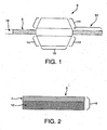
Figure 1 shows a schematic of a wrapped balloon created by the method of the present invention. -
Figure 2 shows a balloon material with a single side coating.Figure 3 shows a balloon material with a double sided coating. -
Figure 4 shows a schematic of a partially wrapped balloon. -
Figure 5 shows a cross section of wrapped balloon on a core. -
Figure 6 shows a cross section of wrapped balloon on a core with a cigarette wrapped second balloon material pass.Figure 7 shows a cross section of wrapped balloon on a core with a cigarette wrapped second balloon material pass and non-distending regions. -
Figure 8 shows a cross section of wrapped balloon on a core with an overlapped cigarette wrap of second balloon material pass. -
Figure 9 shows a mold-shaped catheter balloon with non-distensible regions. -
Figure 10 shows a cross-section view of a wrapped balloon with non- distensible regions. - The balloon catheter created by the method of the present invention in its simplest form comprises a catheter shaft having a longitudinal axis and an inflatable balloon affixed thereto. The balloon is comprised of at least two passes. An individual pass is comprised of one or more layers of material which are laid at a similar angle in relation to the longitudinal axis of the balloon. A layer is considered to be one thickness of balloon material which may be wrapped, folded, laid or weaved over, around, beside or under another thickness. A longitudinal pass comprises a distinctive layer or series of layers of material which are wound to form a region or area distinct from surrounding or adjoining parts. For instance a pass may comprise multiple layers of balloon material wrapped at a 90 degree angle relative to the longitudinal axis. This exemplary pass may then be flanked by layers of balloon material wrapped at dissimilar angles in relation to the longitudinal axis, thus defining the boundary of the pass.
- A pass of balloon material may be oriented helically, radially or longitudinally. By layers of balloon material it is meant to include pieces, threads, layers, filaments, membranes, or sheets of suitable balloon material. In helically oriented layers, the material is oriented so to form a balanced force angle in relation to each other upon inflation. The layers may further be wound upon themselves in subsequent passes. A balanced force balloon of the present invention is a balloon possessing a combination of passes to create the strength to balance the radial force exerted by inflation pressures on the balloon vessel with respect to the longitudinal forces exerted by inflation so that the balloon inflates to its desired diameter without any longitudinal movement. One method of achieving a balanced-force-angle balloon is to orient the helical layers to approach the geometrically derived neutral angle value of 54.7 degrees. This neutral angle is derived from balancing the forces in a thin walled pressure vessel where: 2 x Axial stress = Hoop stress. The inflatable balloon created by the method of the present invention exhibits both essentially radial symmetry upon inflation and non-foreshortening. Radial symmetry is exhibited upon inflation as the movement of the balloon material away from the center point of the lumen in a direct radial fashion so that the balloon maintains a relatively radial outward movement which resists twisting of the balloon surface as the balloon inflates. By non-foreshortening it is meant that the length of the balloon does not change by more than ten percent upon inflation to a rated burst pressure. In preferred applications, the balloon does not change length by more than 5 percent upon inflation to a rated burst pressure. In further preferred applications, the balloon does not change length by more than 2 percent upon inflation to a rated burst pressure. A radial symmetry upon inflation allows the balloon to exhibit an equal hydrostatic force on a vessel wall in clinical use. When used with a stent or stent graft, an equal hydrostatic force allows uniform deployment capability. Uniform stent deployment is preferred so that less trauma is inflicted on the vessels and more efficient vessel scaffolding is achieved, as compared to other types of deployment. In one embodiment as shown in
Figure 1 , an inflatable device comprises acatheter shaft 18 having a longitudinal axis and aninflatable balloon 9 affixed to the shaft, the balloon has an un-inflated length which remains relatively unchanged as the balloon is inflated and comprises at least two helical wrap passes of aballoon material 6. The at least two passes may be fused together. The balloon has a workinglength 15, shoulders 14, and wrappedballoon material 6 on thelegs 50 of the balloon. As shown inFigure 2 , theballoon material 6 comprises a porous reinforcing polymer 1 and apolymer coating 2. The polymer coating is imbibed into the porous reinforcing polymer to form acontinuous polymer layer 12. The porous reinforcing polymer may comprise a fibrous reinforcement, a porous membrane such as, a polyolefin, a fluoropolymer, a discontinuous phase of a polymer, or an oriented microporous reinforcement, such as ePTFE. It is desirable to use expanded PTFE (ePTFE) as a porous reinforcing polymer, allowing the balloon material to realize a matrix tensile value in one direction greater than 690 megapascals; or preferably greater than 960 megapascals; more preferably greater than 1,200 megapascals. - The oriented microporous reinforcement may be a fluoropolymer, a polyamide, a polyurethane, a polyester, a PEEK, a reinforced polymer, or any other suitable materials or combination of materials. The
polymer coating 2 is imbibed throughout the porous reinforcing polymer and may comprise a fluoropolymer, an elastomer, a urethane, a silicone, a styrene block copolymer, a fluoro-elastomer, a bioresorbable material or any other suitable polymer. As further shown inFigure 1 , the balloon comprises a workinglength 15 between twoshoulders 14 of the balloon. In an embodiment, the balloon comprises at least one hoop pass wrapped over the working length and a shoulder pass having a thickness ratio between the hoop layer and the shoulder layer of 2:1. The balloon material layers forming the individual passes may be heated or set in position relative to each other after each pass. - Typical low angle wrapped balloons tend to foreshorten as they inflate and the wrap angle rotates towards the neutral angle. Less obvious is that the wrap layers also strain perpendicular to the wrap angle during the rotation caused by inflation. The growth in the wrap layer width follows this geometrically derived equation: (WidthF = Widthi x (cos□F/cos□i)2 x (tan□F/tan□i) where F is final and I is initial, and □ is the angle of the helical wrap relative to the longitudinal axis of the balloon. This strain can exceed 500 percent in some balloons depending on the deflated to inflated ratio. Highly anisotropic materials are necessary to allow this perpendicular stain. The wrap layers when configured in accordance with the method of the present invention, reset a low angle wrapped balloon at or near a balanced force angle which prevents the layers from incurring transverse strain in subsequent balloon inflations. Additionally, the balloon exhibits essentially radial symmetry upon inflation. The balloon is wrapped by winding layers at opposing directions to one another until a desired thickness is obtained. The balloon material passes may be comprised of the same materials or different materials. While the thickness of the materials may vary, for vascular use it is advantageous to use balloon material that is about 4- 6 micrometers thick. As shown in
Figures 2 and3 , a balloon material comprising apolymer layer 2 is coated on the porous reinforcement polymer 1 allowing the polymer coating to fill the void spaces of the porous reinforcement polymer 1. Thepolymer layer 2 may desirably fill the void spaces in the porous reinforcement polymer 1 to form a filledpolymer layer 12. Thepolymer layer 2 may be formed on one side of the porous reinforcing polymer 1 (Figure 2 ) or on both sides of the porous reinforcing polymer 1 (Figure 3 ). The composite film 3 may further comprise a filler. The filler may provide benefits such as radio opaque marking or therapeutic value. The balloon material may be cut into more narrow widths if necessary to form wrapping layers used in the balloon. An anisotropic material is used as a wrap layer in balloon passes consisting of wrap layer angles of less than about 55 degrees. However, if an overwrap pass is employed it may comprise isotropic or anisotropic material depending on desired applications. - The composite film 3 created by the method of the present invention comprises a porous reinforcing layer and a continuous polymer layer as depicted in
Figures 2 and3 . The porous reinforcing polymer layer 1 is preferably a thin strong porous membrane that can be made in sheet form. The porous reinforcing polymer can be selected from a group of polymers including but not limited to: olefin, PEEK, polyamide, polyurethane, polyester, polyethylene, and polytetrafluoroethylene. In an example, the porous reinforcing polymer is expanded polytetrafluoroethylene (ePTFE) made in accordance with the general teachings ofUS Patent No. 5,476,589 andUS Patent Application No. 11/334,243 - The
continuous polymer layer 2 created by the method of the present invention is coated onto at least one side of the porous reinforcing polymer 1 as depicted inFigures 2 &3 . The continuous polymer layer is preferably an elastomer, such as but not limited to, aromatic and aliphatic polyurethanes including copolymers, styrene block copolymers, silicones, preferably thermoplastic silicones, fluoro-silicones, fluoroelastomer, THV and latex. In one example of the method of the present invention, thecontinuous polymer layer 2 is coated onto only one side of the porous reinforcing polymer 1, as shown inFigure 2 . As depicted inFigure 3 , thecontinuous polymer layer 2 is coated onto both sides of the porous reinforcing polymer 1. In one aspect, thecontinuous polymer layer 2 is imbibed into the porous reinforcing polymer 1 and the imbibedpolymer 2 fills the pores of the porous reinforcing polymer 1 to form a composite 12. - The continuous polymer layer can be applied to the porous reinforcing polymer through any number of conventional methods including but not limited to, lamination, transfer roll coating, wire-wound bar coating, reverse roll coating, and solution coating or solution imbibing. In an example , the continuous polymer layer is solution imbibed into the porous reinforcing polymer. In this example, the continuous, polymer layer polymer is dissolved in a suitable solvent and coated onto and throughout the porous reinforcing polymer using a wire-wound rod process. The coated porous reinforcing polymer is then passed through a solvent oven and the solvent is removed leaving a continuous polymer layer coated onto and throughout the porous reinforcing polymer. In some cases, such as when silicone is used as the continuous polymer layer, the coated porous reinforcing polymer may not require the removal of solvent. In another example, the continuous polymer layer is coated onto at least one side of the porous reinforcing polymer and maintained in a "green" state where it can be subsequently cured. For example, an ultraviolet light (UV) curable urethane may be used as the continuous polymer layer and coated onto the porous reinforcing polymer. The composite film comprising the porous reinforcing polymer and the UV curable urethane continuous polymer layer can then be wrapped to form at least one layer of the balloon and subsequently exposed to UV light and cured.
- In another aspect of this invention, the helically wrapped passes of balloon material are bonded to each other. A preferred bonding technique is heat. The balloon material is then annealed in the inflated state through the application of heat to reset the low angle wrap balloon perform at or near a balanced force angle.
- As shown in
Figures 4 and5 , thefirst balloon material 6 may be wrapped around a core wire 4. The core wire 4 may be coated with arelease agent 5, such as an FEP coating or other suitable agent. The helical wrap layers are first laid across the longitudinal axis in one direction or pass. A second pass lays another heticat wrap layer in the opposing direction. Both passes 6 are oriented at an angle of less than or equal to about 55 degrees with respect to the longitudinal axis but in opposing directions.Figure 5 shows thatnon-distensible layers 7 may be present to formnon-distensible regions 8. The helically wrap layers of a first balloon material pass may be bonded to a second balloon material pass through the application of heat, or another suitable bonding technique. These balloon preforms are wrapped at a low angle to facilitate sealing to a catheter shaft. The distensible region of the preform is then inflated and the helical wrapped layers of the first material are reset at a balanced force angle through heating, solvating; annealing, or through a second material added while in the inflated state. The second material may be comprised of the same or different materials as the first material. - In one preferred embodiment as shown in
Figures 6 and8 , aballoon material 6 is wrapped into at least two passes to form a balloon preform and then is fused and inflated to form the shape of a catheter balloon. Theballoon material 6 is then held at balanced force angle by secondballoon material layer 11 which is cigarette wrapped around the first balloon material at an angle greater than 54 degrees relative to the longitudinal axis of the catheter balloon. It is preferred that two ends of the second balloon material overlap to form a longitudinally orientedseam 13, as shown inFigure 8 . - In another preferred embodiment as shown in
Figure 7 and9 , aballoon material 6 is wrapped into a low angle balloon preform. The balloon is inflated in aninflation mold 10 as shown inFigure 9 . Theinflation mold 10 is of a desired shape to form a catheter balloon which is then held at balanced force angle by second pass ofballoon material 11 that is helically wrapped around the molded catheter balloon at an angle greater than 54 degrees but not greater than 90 degrees relative to the longitudinal axis of the catheter balloon. Anon-distensible region 8 may be included in the balloon as shown inFigures 5 ,7 , and9 . Thenon-distending regions 8 are focal regions which are more resistant to radial dilatation allowing for reduction of load or sealing of an inflated balloon to an underlying catheter shaft. Anon-distending region 8 comprises a plurality ofnon-distensible layers 7 which wind around theballoon material 6 and overlap to form an angle of between 0 degrees to 90 degrees relative to the longitudinal axis of the balloon. Thenon-distending regions 8 are incorporated or integrated into the surface of the balloon wall, into the balloon wall, or under the outer most surface of the balloon wall. Thenon-distending regions 8 are in direct continuity with the balloon wall and are virtually indistinguishable in form from the balloon wall in an un-inflated state. - The
second balloon material 11 may be isotropic, having a relatively equal strength in all directions or anisotropic having an oriented longitudinal strength. The balloons created by the method of the present invention expand from a low-profile delivery configuration to an inflated configuration in a uniform concentric manner over substantially its entire working length. The present invention is applicable for use with non-compliant or semi-compliant balloons. - In another embodiment, the inventive balloon created according to the method of the present invention comprises a
balloon material 6 wrapped into a low angle preform and inflated to form the shape of a catheter balloon which is then further wrapped and held at a balanced force angle by a pass or passes of second balloon material oriented at an angle greater than 54 degrees with respect to the longitudinal balloon axis. It is desirable to orient the second balloon material helically in direction of the maximum hoop stress to create a high pressure balloon. It is desirable to use ePTFE as the porous reinforcing polymer in the composite film of a balloon layer to achieve a maximum hoop stress of the helically wrapped layers in greater than 400 megapascals. Even more desirable is achieving a maximum hoop stress of the helically wrapped layers in greater than 600 megapascals. - The balloon materials may comprise a filler if desired to alleviate leakage of the membrane or to deliver therapeutic agents. The filler may be radio opaque or provide therapeutic value. The balloon may further comprise one or more integral non-distending regions, as described above. An integral non-distending region may be located between two or more layers of balloon material or located on the surface of a
balloon material 6 to form a non- distending region 8 (seeFigures 5 and10). Figure 10 shows a core wire 4 with arelease agent 5, aballoon material 6 and a surface mountednon-distensible layer 7 forming a seal. The non-distending region, as depicted inFigure 5 , is formed by changing the wrapping angle of the balloon material layers to create a build up of non-distending passes. The non-distending passes overlap each other either wholly or partially to form one or morenon-distending regions 8 on the wrapped distensible balloon. Thenon-distending regions 8 are significantly less compliant under distention force than a distensible main body of the balloon. The non-distending region may comprise the same material as adistensible balloon material 6 or a different material. It is preferable that thenon-distending region 8 undergoes little or no change in radial diameter upon introduction of distention force. - The method of the present invention further contemplates creating la balloon catheter comprising a catheter shaft with a longitudinal axis and an inflatable balloon of the present invention affixed to the shaft. A catheter balloon created by the method of the present invention may be used in conjunction with a stent. When at least the second balloon material exhibits a low modulus, the balloon material is able to pillow into the stent interstices. Thus, the pillow areas which fill in the interstices of a stent provide stent embedment prior to stent delivery. In this manner the stent is embedded without the use of heat, and without balloon inflation.
- A method of creating a non-shortening catheter balloon with increased burst pressures is also provided, comprising wrapping a wire core with a plurality of balloon material layers or pieces at a angle of less than 15 degrees relative to the longitudinal axis of the balloon to form a balloon preform; exposing the plurality of balloon material layers to heat to bond them together; removing the core; and then further exposing the balloon preform to internal pressure at a reflow temperature. The reflow temperature is the temperature to soften or a melt point for the film or imbibing material; and inflating the balloon preform into a balloon as it is continued to be exposed to said internal pressure at an increased temperature. At this point if desired the balloon may be wrapped with a second balloon material layer at a high angle of between 54 and 90 degrees. The second balloon material may be fused to the inflated balloon by the application of heat or other desired bonding technique. The balloon is then removed from exposure to reflow temperature and internal pressure to create a non-shortening balloon. When a second balloon material is used it may be fused to the inflated balloon by the application of heat or other desired bonding technique. Further, an inflation mold may be used to inflate the balloon using heat and pressure so that a desired balloon shape results prior to passing the second balloon material layer. The second balloon material may be cigarette wrapped or helically wrapped.
- A yet further example of creating a non-shortening catheter balloon with increased burst pressures is also provided, comprising wrapping a mandrel with a plurality of anisotropic first balloon material layers at a low angle of between 3 and 54 degrees relative to the longitudinal axis to form a balloon preform, these first balloon layers may be oriented in opposing directions relative to the longitudinal balloon axis; exposing the plurality of balloon material layers to heat to bond them together creating a preform; placing the balloon preform in a mold and exposing the balloon preform to internal pressure; inflating the balloon preform as it is continued to be exposed to said internal pressure creating a balloon; and removing the balloon from the mold; and wrapping the inflated balloon with a second balloon material layer at an angle between 54 and 90 degrees to form a high pressure catheter balloon. The second balloon material may be isotropic or anisotropic. The mandrel may be a wire or any other suitable core material to provide a hollow body upon removal from the balloon material. In this method a balloon may be created with the addition of heat and pressure so that no mold is needed. Alternatively, as heat and pressure are added, the balloon may be inflated into a mold. Additionally, it may be desirable in some shaped balloons to have a catheter shaft comprising a reinforced inner member located adjacent to the longitudinal axis of the balloon and between the shaft and the balloon wherein the reinforced inner member is modulated to compensate for shape shifting or pressure changes in the balloon so as to prevent movement of the catheter balloon upon inflation. The catheter shaft may also comprise an expandable pleated shaft section located adjacent to the longitudinal axis of the balloon wherein the expandable pleated shaft section is formed to compensate for movement or shifting in the balloon upon inflation. To increase the bonding of the seals of the shaped balloon, a catheter shaft comprising an outer seal dimension having both convex portions and concave portions which provide an increased surface area and increased seal strength when attached to the balloon ends. The following examples are provided to illustrate the present invention.
- While particular embodiments of the present invention have been illustrated and described herein, the present invention should not be limited to such illustrations and descriptions. It should be apparent that changes and modifications may be incorporated and embodied as part of the present invention within the scope of the following claims.
- The ePTFE membrane used to make the composite film was made in accordance with the teaching in
US Patent 5,476,589 to Bacino . Specifically, the ePTFE membrane was longitudinally expanded to a ratio of 55 to 1 and transversely expanded approximately 2.25 to 1, to produce a thin strong membrane with fibrils oriented substantially in the longitudinal direction, and a mass of approximately 3.5g/m2 and a thickness of approximately 6.5 micrometers. - The composite film was made by using a saturation coating process whereby a solution of Tecothane TT-1085A polyurethane and tetrahydrofuran (THF) was coated onto the ePTFE membrane using a wire-wound rod coating process. A 3% to 8% by weight solution of Tecothane TT-1085A polyurethane in THF was saturation coated onto the ePTFE membrane to produce a composite film with approximately equal amounts of Tecothane TT- 1085A polyurethane on either side of the ePTFE membrane and a total polymer weight application of approximately 50% to 60% of the total final composite film weight.
- A mechanically balanced composite film was made by using a wire- wound rod coating process whereby a solution of Tecothane TT-1085A polyurethane and tetrahydrofuran (THF) was coated onto an ePTFE membrane. The ePTFE membrane used to make the composite film was made in accordance with the teachings of
US Patent Application No. 11/334,243 - A mechanically balanced composite film was made by using a saturation coating process whereby a solution of Tecothane TT-1085A polyurethane and tetrahydrofuran (THF) was coated onto an ePTFE membrane using a wire-wound rod coating process. The ePTFE membrane used to make the composite film was made in accordance with the teachings in Example (2). Specifically, the ePTFE membrane was longitudinally expanded to a ratio of 15 to 1 and transversely expanded approximately 28 to 1 , to produce a thin strong membrane with an mass of approximately 3.1 g/m2 and a thickness of approximately 8 micrometers. A 3% to 8% by weight solution of Tecothane TT- 1085A polyurethane in THF was saturation coated onto the ePTFE membrane to produce a composite film with approximately equal amounts of Tecothane TT-1085A polyurethane on either side of the ePTFE membrane and a total polymer weight application of approximately 40% to 50% of the total final composite film weight.
- The composite balloons created by the method of the present invention were evaluated on an inflation tester (Interface Associates model PT3070, Laguna Nigel, CA). The inflation tester was filled with distilled, de-ionized water. A balloon was connected to the inflation tester and equilibrated in a water circulation bath (Polyscience Model 210, Niles, IL) at 37C for 5 minutes. The balloons were cycled three times to 5 atmospheres of pressure at a rate of 6 atmospheres per minute, held at 5 atmospheres of pressure for 10 seconds, and then ramped back down at 6 atmospheres per minute. After cycling the pressure was increased in increments of 1 atmosphere every 10 seconds. The diameter was recorded at each pressure increment with a laser micrometer (Keyence Model LS-7501, Wooddiff Lake, NJ). The length was manually measured with a micrometer (Mit[upsilon]toyo Absolute Digimatic 500-196, Aurora, IL) several times during the pressure ramp, and the pressure value was recorded for each length measurement taken.
- The inflatable balloon created by the method of the present invention was made by wrapping a composite film of Tecothane TT-1085A polyurethane (Thermedics, Inc, Woburn, MA), and ePTFE membrane, as described in Example 1 , over a FEP coated silver plated copper wire (Putnam Plastics LLC, Dayville, CT). The 0.394 mm diameter wire core was deadsoft copper with silver plating and a 0.2mm fluorinated ethylene-propylene (FEP) coating.
- The composite film was slit to 5mm wide and wrapped around the wire at a 4 to 5 degree angle from the longitudinal axis of the wire. The wrapped wire was heated for approximately 5 to 30 seconds at 180C after wrapping. The wire was then wrapped with the composite film in the opposite direction at a 4 to 5 degree angle from the longitudinal axis of the wire and subsequently heated for approximately 5 to 30 seconds at 180C. The process of wrapping the wire in opposite directions and heating after each pass was repeated until a total of four passes of wrapping was complete. The wrapped wire was wrapped around a pin frame with approximately 30cm spaces between pins and approximately 180 degrees of wrap around each pin and tied at the ends before being placed into an oven and heated for approximately 30 minutes at 150C, removed, and permitted to cool to ambient.
- From the balloon detailed in Example 5, approximately a 2.54 cm section of the composite hollow balloon tube was removed from either end of a longer section of the balloon. The exposed ends of the wire were clamped with hemostats and pulled by hand until the wire had been stretched approximately 5 cm, at which point it was removed from the center of the tube. The plastic FEP coating was removed in a similar fashion, but was stretched approximately 50 cm before it was removed from the balloon.
- The hollow balloon was clamped on one side with a hemostat, and Monoject blunt needle with Aluminum luer lock hub (model # 8881-202389, Sherwood Medical, St. Louis MO) was inserted approximately 2cm into the open end of the balloon. The hemostatic valve was tightened to seal the balloon, and was then attached to a Balloon Development Station #210A
Claims (2)
- A method of creating a non-shortening balloon with increased burst pressures, said method comprising:a) wrapping a wire core with at least one helically oriented anisotropic balloon material to form a balloon preform;b) exposing the helically oriented anisotropic balloon material to heat;c) removing the wire core;d) exposing the balloon preform to internal pressure at a reflow temperature;e) inflating the balloon preform into a balloon as it is continued to be exposed to said internal pressure at an increased temperature; andf) removing heat and internal pressure;wherein the wire core of step (a) is wrapped with at least two helically wrapped passes of the balloon material, in opposing directions, each with a wrap angle of less than 15 degrees with respect to the longitudinal axis.
- The method of claim 1, further comprising step (f)(1) inflating the non- shortening balloon and wrapping with a second balloon material pass at a high angle of between 54 and 90 degrees, and optionally further comprising step (f)(2) passing heat to bond said second balloon pass to the inflated balloon; or
wherein the heat and pressure are added and the balloon is inflated into a mold; or
wherein the heat and pressure are added and the balloon is inflated without a mold; or
wherein a second balloon material is cigarette wrapped; or
wherein a second balloon material is helically wrapped.
Priority Applications (1)
| Application Number | Priority Date | Filing Date | Title |
|---|---|---|---|
| EP15182992.6A EP2995340A1 (en) | 2006-08-07 | 2007-08-02 | Non-shortening wrapped balloon |
Applications Claiming Priority (2)
| Application Number | Priority Date | Filing Date | Title |
|---|---|---|---|
| US11/501,249 US20080140173A1 (en) | 2006-08-07 | 2006-08-07 | Non-shortening wrapped balloon |
| PCT/US2007/017218 WO2008021006A2 (en) | 2006-08-07 | 2007-08-02 | Non-shortening wrapped balloon |
Related Child Applications (2)
| Application Number | Title | Priority Date | Filing Date |
|---|---|---|---|
| EP15182992.6A Division-Into EP2995340A1 (en) | 2006-08-07 | 2007-08-02 | Non-shortening wrapped balloon |
| EP15182992.6A Division EP2995340A1 (en) | 2006-08-07 | 2007-08-02 | Non-shortening wrapped balloon |
Publications (3)
| Publication Number | Publication Date |
|---|---|
| EP2049189A2 EP2049189A2 (en) | 2009-04-22 |
| EP2049189B1 true EP2049189B1 (en) | 2015-10-07 |
| EP2049189B8 EP2049189B8 (en) | 2015-12-23 |
Family
ID=39082527
Family Applications (2)
| Application Number | Title | Priority Date | Filing Date |
|---|---|---|---|
| EP15182992.6A Pending EP2995340A1 (en) | 2006-08-07 | 2007-08-02 | Non-shortening wrapped balloon |
| EP07836423.9A Active EP2049189B8 (en) | 2006-08-07 | 2007-08-02 | Method of creating a non-shortening wrapped balloon |
Family Applications Before (1)
| Application Number | Title | Priority Date | Filing Date |
|---|---|---|---|
| EP15182992.6A Pending EP2995340A1 (en) | 2006-08-07 | 2007-08-02 | Non-shortening wrapped balloon |
Country Status (8)
| Country | Link |
|---|---|
| US (4) | US20080140173A1 (en) |
| EP (2) | EP2995340A1 (en) |
| JP (1) | JP2010500108A (en) |
| AU (1) | AU2007284904A1 (en) |
| CA (1) | CA2660066A1 (en) |
| ES (1) | ES2557910T3 (en) |
| HK (1) | HK1216089A1 (en) |
| WO (1) | WO2008021006A2 (en) |
Families Citing this family (64)
| Publication number | Priority date | Publication date | Assignee | Title |
|---|---|---|---|---|
| US20080097300A1 (en) * | 2006-08-07 | 2008-04-24 | Sherif Eskaros | Catheter balloon with multiple micropleats |
| US20080125711A1 (en) * | 2006-08-07 | 2008-05-29 | Alpini Alfred A | Catheter balloons with integrated non-distensible seals |
| US20080140173A1 (en) * | 2006-08-07 | 2008-06-12 | Sherif Eskaros | Non-shortening wrapped balloon |
| US7785290B2 (en) * | 2006-08-07 | 2010-08-31 | Gore Enterprise Holdings, Inc. | Non-shortening high angle wrapped balloons |
| US9180279B2 (en) * | 2006-08-07 | 2015-11-10 | W. L. Gore & Associates, Inc. | Inflatable imbibed polymer devices |
| US8460240B2 (en) * | 2006-08-07 | 2013-06-11 | W. L. Gore & Associates, Inc. | Inflatable toroidal-shaped balloons |
| US8043296B2 (en) * | 2006-08-25 | 2011-10-25 | Kyphon Sarl | Apparatus and methods for use of expandable members in surgical applications |
| US9622888B2 (en) | 2006-11-16 | 2017-04-18 | W. L. Gore & Associates, Inc. | Stent having flexibly connected adjacent stent elements |
| WO2008095052A2 (en) | 2007-01-30 | 2008-08-07 | Loma Vista Medical, Inc., | Biological navigation device |
| US20100241178A1 (en) * | 2008-06-02 | 2010-09-23 | Loma Vista Medical, Inc. | Inflatable medical devices |
| US8926688B2 (en) | 2008-01-11 | 2015-01-06 | W. L. Gore & Assoc. Inc. | Stent having adjacent elements connected by flexible webs |
| JP2011522589A (en) | 2008-06-04 | 2011-08-04 | ゴア エンタープライズ ホールディングス,インコーポレイティド | Introducer sheath valve for medical procedures with a collapsible tubular diaphragm |
| US8509274B2 (en) * | 2009-01-08 | 2013-08-13 | Quantum Electro Opto Systems Sdn. Bhd. | Light emitting and lasing semiconductor methods and devices |
| EP2593171B1 (en) | 2010-07-13 | 2019-08-28 | Loma Vista Medical, Inc. | Inflatable medical devices |
| US10188436B2 (en) | 2010-11-09 | 2019-01-29 | Loma Vista Medical, Inc. | Inflatable medical devices |
| US9839540B2 (en) | 2011-01-14 | 2017-12-12 | W. L. Gore & Associates, Inc. | Stent |
| US10016579B2 (en) | 2011-06-23 | 2018-07-10 | W.L. Gore & Associates, Inc. | Controllable inflation profile balloon cover apparatus |
| US9370643B2 (en) | 2011-06-23 | 2016-06-21 | W.L. Gore & Associates, Inc. | High strength balloon cover |
| US10213329B2 (en) * | 2011-08-12 | 2019-02-26 | W. L. Gore & Associates, Inc. | Evertable sheath devices, systems, and methods |
| US9808605B2 (en) | 2011-10-06 | 2017-11-07 | W. L. Gore & Associates, Inc. | Controlled porosity devices for tissue treatments, methods of use, and methods of manufacture |
| US9730726B2 (en) | 2011-10-07 | 2017-08-15 | W. L. Gore & Associates, Inc. | Balloon assemblies having controllably variable topographies |
| US9283072B2 (en) | 2012-07-25 | 2016-03-15 | W. L. Gore & Associates, Inc. | Everting transcatheter valve and methods |
| US9563663B2 (en) | 2012-09-28 | 2017-02-07 | Oracle International Corporation | Fast path evaluation of Boolean predicates |
| US10850076B2 (en) | 2012-10-26 | 2020-12-01 | Urotronic, Inc. | Balloon catheters for body lumens |
| CN111166942A (en) | 2012-10-26 | 2020-05-19 | 优敦力公司 | Drug-coated balloon catheter for non-vascular stenosis |
| US10898700B2 (en) | 2012-10-26 | 2021-01-26 | Urotronic, Inc. | Balloon catheters for body lumens |
| US10806830B2 (en) | 2012-10-26 | 2020-10-20 | Urotronic, Inc. | Drug-coated balloon catheters for body lumens |
| US11938287B2 (en) | 2012-10-26 | 2024-03-26 | Urotronic, Inc. | Drug-coated balloon catheters for body lumens |
| US11504450B2 (en) | 2012-10-26 | 2022-11-22 | Urotronic, Inc. | Drug-coated balloon catheters for body lumens |
| US10881839B2 (en) | 2012-10-26 | 2021-01-05 | Urotronic, Inc. | Drug-coated balloon catheters for body lumens |
| US9931193B2 (en) | 2012-11-13 | 2018-04-03 | W. L. Gore & Associates, Inc. | Elastic stent graft |
| US9144492B2 (en) | 2012-12-19 | 2015-09-29 | W. L. Gore & Associates, Inc. | Truncated leaflet for prosthetic heart valves, preformed valve |
| US9101469B2 (en) | 2012-12-19 | 2015-08-11 | W. L. Gore & Associates, Inc. | Prosthetic heart valve with leaflet shelving |
| US9968443B2 (en) | 2012-12-19 | 2018-05-15 | W. L. Gore & Associates, Inc. | Vertical coaptation zone in a planar portion of prosthetic heart valve leaflet |
| US10279084B2 (en) * | 2012-12-19 | 2019-05-07 | W. L. Gore & Associates, Inc. | Medical balloon devices and methods |
| US9763819B1 (en) | 2013-03-05 | 2017-09-19 | W. L. Gore & Associates, Inc. | Tapered sleeve |
| US9669194B2 (en) | 2013-03-14 | 2017-06-06 | W. L. Gore & Associates, Inc. | Conformable balloon devices and methods |
| US9770352B2 (en) | 2013-03-14 | 2017-09-26 | W. L. Gore & Associates, Inc. | Inflatable balloon and cover |
| US11116947B2 (en) * | 2013-03-15 | 2021-09-14 | W. L. Gore & Associates, Inc. | Balloon seal stress reduction and related systems and methods |
| US9788858B2 (en) | 2013-04-15 | 2017-10-17 | Transseptal Solutions Ltd. | Fossa ovalis penetration using probing elements |
| US9545265B2 (en) * | 2013-04-15 | 2017-01-17 | Transseptal Solutions Ltd. | Fossa ovalis penetration using balloons |
| US10842918B2 (en) | 2013-12-05 | 2020-11-24 | W.L. Gore & Associates, Inc. | Length extensible implantable device and methods for making such devices |
| US9907641B2 (en) | 2014-01-10 | 2018-03-06 | W. L. Gore & Associates, Inc. | Implantable intraluminal device |
| US10966850B2 (en) | 2014-03-06 | 2021-04-06 | W. L. Gore & Associates, Inc. | Implantable medical device constraint and deployment apparatus |
| US9827094B2 (en) | 2014-09-15 | 2017-11-28 | W. L. Gore & Associates, Inc. | Prosthetic heart valve with retention elements |
| EP3206603B1 (en) | 2014-10-14 | 2019-10-02 | Transseptal Solutions Ltd. | Fossa ovalis penetration apparatus |
| US10299948B2 (en) | 2014-11-26 | 2019-05-28 | W. L. Gore & Associates, Inc. | Balloon expandable endoprosthesis |
| US9706982B2 (en) | 2015-03-03 | 2017-07-18 | Transseptal Solutions Ltd. | Treatment of appendage openings |
| US10888640B2 (en) | 2015-04-24 | 2021-01-12 | Urotronic, Inc. | Drug coated balloon catheters for nonvascular strictures |
| US11904072B2 (en) | 2015-04-24 | 2024-02-20 | Urotronic, Inc. | Drug coated balloon catheters for nonvascular strictures |
| US10398503B2 (en) | 2015-10-14 | 2019-09-03 | Transseptal Soulutions Ltd. | Fossa ovalis penetration |
| ES2956016T3 (en) | 2016-04-21 | 2023-12-11 | Gore & Ass | Diametrically adjustable endoprostheses |
| US10568752B2 (en) | 2016-05-25 | 2020-02-25 | W. L. Gore & Associates, Inc. | Controlled endoprosthesis balloon expansion |
| CN107050625B (en) * | 2017-01-17 | 2023-05-23 | 重庆市江津区中心医院 | Deep insertion-preventing reinforced supporting type guiding catheter |
| EP3442612B1 (en) * | 2017-05-05 | 2020-08-05 | Urotronic, Inc. | Drug-coated balloon catheters for body lumens |
| CN109480997A (en) * | 2017-09-11 | 2019-03-19 | 上海微创医疗器械(集团)有限公司 | Cryoablation sacculus and cryoablation medical instrument |
| AU2018342222B2 (en) | 2017-09-27 | 2021-05-20 | Edwards Lifesciences Corporation | Prosthetic valve with expandable frame and associated systems and methods |
| US11540933B2 (en) | 2017-10-11 | 2023-01-03 | W. L. Gore & Associates, Inc. | Implantable medical device constraint and deployment apparatus |
| US11439502B2 (en) | 2017-10-31 | 2022-09-13 | W. L. Gore & Associates, Inc. | Medical valve and leaflet promoting tissue ingrowth |
| CN113727750A (en) | 2019-02-22 | 2021-11-30 | 优敦力公司 | Drug-coated balloon catheter for body lumens |
| US11497601B2 (en) | 2019-03-01 | 2022-11-15 | W. L. Gore & Associates, Inc. | Telescoping prosthetic valve with retention element |
| KR20220019291A (en) * | 2019-06-13 | 2022-02-16 | 더블유.엘. 고어 앤드 어소시에이트스, 인코포레이티드 | Highly oriented expanded polytetrafluoroethylene with good stiffness |
| EP3983197A1 (en) * | 2019-06-13 | 2022-04-20 | W.L. Gore & Associates Inc. | Lightweight expanded polytetrafluoroethylene membranes having high intrinsic strength and optical transparency |
| WO2023018707A1 (en) * | 2021-08-09 | 2023-02-16 | Bard Peripheral Vascular, Inc. | Composite medical balloon with enhanced outer film layer and related methods |
Citations (1)
| Publication number | Priority date | Publication date | Assignee | Title |
|---|---|---|---|---|
| US6923827B2 (en) * | 1995-09-18 | 2005-08-02 | Gore Enterprise Holdings, Inc. | Balloon catheter device |
Family Cites Families (192)
| Publication number | Priority date | Publication date | Assignee | Title |
|---|---|---|---|---|
| US1690995A (en) | 1927-12-28 | 1928-11-06 | Monte Lloyd Corp | Anorectal dilator |
| US3634924A (en) * | 1970-04-20 | 1972-01-18 | American Hospital Supply Corp | Method of making multilumen balloon catheter |
| CA962021A (en) * | 1970-05-21 | 1975-02-04 | Robert W. Gore | Porous products and process therefor |
| US3640282A (en) * | 1970-08-06 | 1972-02-08 | Jack M Kamen | Tracheal tube with normally expanded balloon cuff |
| US4003382A (en) * | 1975-07-25 | 1977-01-18 | Ethicon, Inc. | Retention catheter and method of manufacture |
| US4106509A (en) * | 1976-08-05 | 1978-08-15 | The Kendall Company | Catheters |
| AT348094B (en) | 1977-02-17 | 1979-01-25 | Hanecka Lubomir Dipl Ing | BALLOON CATHETER |
| US4280500A (en) * | 1978-03-31 | 1981-07-28 | Kazuaki Ono | Tubular flexible medical instrument |
| US4194041A (en) * | 1978-06-29 | 1980-03-18 | W. L. Gore & Associates, Inc. | Waterproof laminate |
| JPS6037733B2 (en) | 1978-10-12 | 1985-08-28 | 住友電気工業株式会社 | Tubular organ prosthesis material and its manufacturing method |
| US4713070A (en) | 1978-11-30 | 1987-12-15 | Sumitom Electric Industries, Ltd. | Porous structure of polytetrafluoroethylene and process for production thereof |
| JPS5582884A (en) * | 1978-12-19 | 1980-06-21 | Olympus Optical Co | Flexible tube and its manufacture |
| US4327736A (en) * | 1979-11-20 | 1982-05-04 | Kanji Inoue | Balloon catheter |
| US4608984A (en) | 1980-10-17 | 1986-09-02 | Fogarty Thomas J | Self-retracting dilatation catheter |
| US4338942A (en) * | 1980-10-20 | 1982-07-13 | Fogarty Thomas J | Dilatation catherter apparatus |
| US4403612A (en) | 1980-10-20 | 1983-09-13 | Fogarty Thomas J | Dilatation method |
| US4946464A (en) * | 1981-07-22 | 1990-08-07 | Pevsner Paul H | Method of manufacturing miniature balloon catheter and product thereof |
| US4596839A (en) * | 1981-09-16 | 1986-06-24 | Peters William E | Elastomer PTFE composition |
| DE3235974A1 (en) * | 1981-11-24 | 1983-06-01 | Volkmar Dipl.-Ing. Merkel (FH), 8520 Erlangen | DEVICE FOR REMOVAL OR FOR THE EXPANSION OF CONSTRAINTS IN BODY LIQUID LEADING VESSELS |
| US4443511A (en) * | 1982-11-19 | 1984-04-17 | W. L. Gore & Associates, Inc. | Elastomeric waterproof laminate |
| US4490421A (en) | 1983-07-05 | 1984-12-25 | E. I. Du Pont De Nemours And Company | Balloon and manufacture thereof |
| US4702252A (en) | 1983-10-13 | 1987-10-27 | Smiths Industries Public Limited Company | Catheters |
| US4637396A (en) * | 1984-10-26 | 1987-01-20 | Cook, Incorporated | Balloon catheter |
| US4619641A (en) | 1984-11-13 | 1986-10-28 | Mount Sinai School Of Medicine Of The City University Of New York | Coaxial double lumen anteriovenous grafts |
| US4613544A (en) | 1984-12-04 | 1986-09-23 | Minnesota Mining And Manufacturing Co. | Waterproof, moisture-vapor permeable sheet material and method of making the same |
| US4737219A (en) * | 1985-02-12 | 1988-04-12 | Becton, Dickinson And Company | Method for bonding polyurethane balloons to multilumen catheters |
| US4706670A (en) | 1985-11-26 | 1987-11-17 | Meadox Surgimed A/S | Dilatation catheter |
| US4650466A (en) * | 1985-11-01 | 1987-03-17 | Angiobrade Partners | Angioplasty device |
| US4733665C2 (en) * | 1985-11-07 | 2002-01-29 | Expandable Grafts Partnership | Expandable intraluminal graft and method and apparatus for implanting an expandable intraluminal graft |
| US4764560A (en) * | 1985-11-13 | 1988-08-16 | General Electric Company | Interpenetrating polymeric network comprising polytetrafluoroethylene and polysiloxane |
| JPS62236560A (en) * | 1986-04-09 | 1987-10-16 | テルモ株式会社 | Catheter for repairing blood vessel |
| US4743480A (en) * | 1986-11-13 | 1988-05-10 | W. L. Gore & Associates, Inc. | Apparatus and method for extruding and expanding polytetrafluoroethylene tubing and the products produced thereby |
| US5071609A (en) | 1986-11-26 | 1991-12-10 | Baxter International Inc. | Process of manufacturing porous multi-expanded fluoropolymers |
| US5256143A (en) | 1987-01-06 | 1993-10-26 | Advanced Cardiovascular Systems, Inc. | Self-venting balloon dilatation catheter |
| US5358486A (en) | 1987-01-09 | 1994-10-25 | C. R. Bard, Inc. | Multiple layer high strength balloon for dilatation catheter |
| US4816339A (en) * | 1987-04-28 | 1989-03-28 | Baxter International Inc. | Multi-layered poly(tetrafluoroethylene)/elastomer materials useful for in vivo implantation |
| US5061276A (en) * | 1987-04-28 | 1991-10-29 | Baxter International Inc. | Multi-layered poly(tetrafluoroethylene)/elastomer materials useful for in vivo implantation |
| US4819751A (en) * | 1987-10-16 | 1989-04-11 | Baxter Travenol Laboratories, Inc. | Valvuloplasty catheter and method |
| JP2683750B2 (en) | 1988-06-06 | 1997-12-03 | 住友電気工業株式会社 | Catheter balloon |
| US5499980A (en) * | 1988-08-08 | 1996-03-19 | Scimed Life Systems, Inc. | Polyimide balloon catheter and method of making same |
| US5192296A (en) * | 1988-08-31 | 1993-03-09 | Meadox Medicals, Inc. | Dilatation catheter |
| US4896669A (en) * | 1988-08-31 | 1990-01-30 | Meadox Medicals, Inc. | Dilatation catheter |
| US5236659A (en) * | 1988-10-04 | 1993-08-17 | Cordis Corporation | Tailoring expansion properties of balloons for medical devices |
| US5087244A (en) * | 1989-01-31 | 1992-02-11 | C. R. Bard, Inc. | Catheter and method for locally applying medication to the wall of a blood vessel or other body lumen |
| CA1329091C (en) * | 1989-01-31 | 1994-05-03 | Geoffrey S. Martin | Catheter with balloon retainer |
| US5171297A (en) | 1989-03-17 | 1992-12-15 | Angeion Corporation | Balloon catheter |
| US5137512A (en) * | 1989-03-17 | 1992-08-11 | Scimed Life Systems, Inc. | Multisegment balloon protector for dilatation catheter |
| US5112304A (en) * | 1989-03-17 | 1992-05-12 | Angeion Corporation | Balloon catheter |
| US5147302A (en) * | 1989-04-21 | 1992-09-15 | Scimed Life Systems, Inc. | Method of shaping a balloon of a balloon catheter |
| US5100429A (en) * | 1989-04-28 | 1992-03-31 | C. R. Bard, Inc. | Endovascular stent and delivery system |
| JP2545981B2 (en) * | 1989-05-09 | 1996-10-23 | 東レ株式会社 | Balloon catheter |
| US5152782A (en) | 1989-05-26 | 1992-10-06 | Impra, Inc. | Non-porous coated ptfe graft |
| US4955899A (en) | 1989-05-26 | 1990-09-11 | Impra, Inc. | Longitudinally compliant vascular graft |
| US5116318A (en) * | 1989-06-06 | 1992-05-26 | Cordis Corporation | Dilatation balloon within an elastic sleeve |
| DE69002295T2 (en) * | 1989-09-25 | 1993-11-04 | Schneider Usa Inc | MULTILAYER EXTRUSION AS A METHOD FOR PRODUCING BALLOONS FOR VESSEL PLASTICS. |
| US5108370A (en) | 1989-10-03 | 1992-04-28 | Paul Walinsky | Perfusion balloon catheter |
| US5478320A (en) | 1989-11-29 | 1995-12-26 | Cordis Corporation | Puncture resistant balloon catheter and method of manufacturing |
| US5290306A (en) * | 1989-11-29 | 1994-03-01 | Cordis Corporation | Puncture resistant balloon catheter |
| US5066298A (en) | 1989-11-30 | 1991-11-19 | Progressive Angioplasty Systems, Inc. | Article and method of sheathing angioplasty balloons |
| DE4018525C2 (en) * | 1990-06-09 | 1994-05-05 | Kaltenbach Martin | Expandable area catheter |
| US5498238A (en) * | 1990-06-15 | 1996-03-12 | Cortrak Medical, Inc. | Simultaneous angioplasty and phoretic drug delivery |
| ATE123658T1 (en) * | 1990-06-15 | 1995-06-15 | Cortrak Medical Inc | DEVICE FOR DISPENSING MEDICATIONS. |
| US5041047A (en) * | 1990-06-28 | 1991-08-20 | Casale Angelo J | Balloon with additional interior display surfaces |
| US5893840A (en) * | 1991-01-04 | 1999-04-13 | Medtronic, Inc. | Releasable microcapsules on balloon catheters |
| US5254090A (en) | 1991-01-14 | 1993-10-19 | Kontron Instruments, Inc. | Balloon catheter having a dual layer inner member |
| US5195969A (en) * | 1991-04-26 | 1993-03-23 | Boston Scientific Corporation | Co-extruded medical balloons and catheter using such balloons |
| US5197978B1 (en) * | 1991-04-26 | 1996-05-28 | Advanced Coronary Tech | Removable heat-recoverable tissue supporting device |
| US5195970A (en) * | 1991-04-26 | 1993-03-23 | Gahara William J | Collapsible balloon catheters |
| US5458568A (en) | 1991-05-24 | 1995-10-17 | Cortrak Medical, Inc. | Porous balloon for selective dilatation and drug delivery |
| US5213576A (en) * | 1991-06-11 | 1993-05-25 | Cordis Corporation | Therapeutic porous balloon catheter |
| CA2074304C (en) | 1991-08-02 | 1996-11-26 | Cyril J. Schweich, Jr. | Drug delivery catheter |
| JPH05192408A (en) * | 1991-09-06 | 1993-08-03 | C R Bard Inc | Production of expansion balloon |
| EP0972535B1 (en) | 1991-09-12 | 2005-12-28 | Advanced Cardiovascular Systems, Inc. | Inflatable member having elastic expansion with limited range |
| US5304214A (en) * | 1992-01-21 | 1994-04-19 | Med Institute, Inc. | Transurethral ablation catheter |
| US5304120A (en) * | 1992-07-01 | 1994-04-19 | Btx Inc. | Electroporation method and apparatus for insertion of drugs and genes into endothelial cells |
| US5342305A (en) * | 1992-08-13 | 1994-08-30 | Cordis Corporation | Variable distention angioplasty balloon assembly |
| US5348538A (en) * | 1992-09-29 | 1994-09-20 | Scimed Life Systems, Inc. | Shrinking balloon catheter having nonlinear or hybrid compliance curve |
| US5500180A (en) * | 1992-09-30 | 1996-03-19 | C. R. Bard, Inc. | Method of making a distensible dilatation balloon using a block copolymer |
| US5466252A (en) | 1992-10-02 | 1995-11-14 | W. L. Gore & Associates, Inc. | Implantable lead |
| US5370618A (en) | 1992-11-20 | 1994-12-06 | World Medical Manufacturing Corporation | Pulmonary artery polyurethane balloon catheter |
| US5342348A (en) * | 1992-12-04 | 1994-08-30 | Kaplan Aaron V | Method and device for treating and enlarging body lumens |
| US5358516A (en) | 1992-12-11 | 1994-10-25 | W. L. Gore & Associates, Inc. | Implantable electrophysiology lead and method of making |
| US5512051A (en) * | 1993-02-16 | 1996-04-30 | Boston Scientific Corporation | Slip-layered catheter balloon |
| US5308356A (en) * | 1993-02-25 | 1994-05-03 | Blackshear Jr Perry L | Passive perfusion angioplasty catheter |
| JP3345786B2 (en) * | 1993-03-17 | 2002-11-18 | ジャパンゴアテックス株式会社 | Flexible tube and method of manufacturing the same |
| JP3243334B2 (en) | 1993-06-10 | 2002-01-07 | テルモ株式会社 | Hydroxyalkanoate polymer composition |
| US5344402A (en) | 1993-06-30 | 1994-09-06 | Cardiovascular Dynamics, Inc. | Low profile perfusion catheter |
| US6159565A (en) * | 1993-08-18 | 2000-12-12 | W. L. Gore & Associates, Inc. | Thin-wall intraluminal graft |
| US6025044A (en) | 1993-08-18 | 2000-02-15 | W. L. Gore & Associates, Inc. | Thin-wall polytetrafluoroethylene tube |
| US6027779A (en) * | 1993-08-18 | 2000-02-22 | W. L. Gore & Associates, Inc. | Thin-wall polytetrafluoroethylene tube |
| US5746745A (en) * | 1993-08-23 | 1998-05-05 | Boston Scientific Corporation | Balloon catheter |
| US5409495A (en) * | 1993-08-24 | 1995-04-25 | Advanced Cardiovascular Systems, Inc. | Apparatus for uniformly implanting a stent |
| GB2281865B (en) * | 1993-09-16 | 1997-07-30 | Cordis Corp | Endoprosthesis having multiple laser welded junctions,method and procedure |
| WO1996014895A1 (en) * | 1994-11-14 | 1996-05-23 | Scimed Life Systems, Inc. | Catheter balloon with retraction coating |
| US5496276A (en) * | 1993-09-20 | 1996-03-05 | Scimed Life Systems, Inc. | Catheter balloon with retraction coating |
| EP0738168B1 (en) * | 1993-10-01 | 2004-01-21 | Boston Scientific Corporation | Medical device balloons containing thermoplastic elastomers |
| US5425710A (en) * | 1993-10-26 | 1995-06-20 | Medtronic, Inc. | Coated sleeve for wrapping dilatation catheter balloons |
| US5484411A (en) * | 1994-01-14 | 1996-01-16 | Cordis Corporation | Spiral shaped perfusion balloon and method of use and manufacture |
| US5429605A (en) * | 1994-01-26 | 1995-07-04 | Target Therapeutics, Inc. | Microballoon catheter |
| US5645560A (en) * | 1995-12-15 | 1997-07-08 | Cardiovascular Dynamics, Inc. | Fixed focal balloon for interactive angioplasty and stent implantation |
| US5843116A (en) | 1996-05-02 | 1998-12-01 | Cardiovascular Dynamics, Inc. | Focalized intraluminal balloons |
| US5470313A (en) | 1994-02-24 | 1995-11-28 | Cardiovascular Dynamics, Inc. | Variable diameter balloon dilatation catheter |
| US5951941A (en) | 1994-03-02 | 1999-09-14 | Scimed Life Systems, Inc. | Block copolymer elastomer catheter balloons |
| US5456661A (en) | 1994-03-31 | 1995-10-10 | Pdt Cardiovascular | Catheter with thermally stable balloon |
| US5458605A (en) | 1994-04-04 | 1995-10-17 | Advanced Cardiovascular Systems, Inc. | Coiled reinforced retractable sleeve for stent delivery catheter |
| US5415636A (en) * | 1994-04-13 | 1995-05-16 | Schneider (Usa) Inc | Dilation-drug delivery catheter |
| US5478349A (en) | 1994-04-28 | 1995-12-26 | Boston Scientific Corporation | Placement of endoprostheses and stents |
| US5499995C1 (en) * | 1994-05-25 | 2002-03-12 | Paul S Teirstein | Body passageway closure apparatus and method of use |
| US5470314A (en) | 1994-07-22 | 1995-11-28 | Walinsky; Paul | Perfusion balloon catheter with differential compliance |
| US5609605A (en) * | 1994-08-25 | 1997-03-11 | Ethicon, Inc. | Combination arterial stent |
| US5499973A (en) * | 1994-09-08 | 1996-03-19 | Saab; Mark A. | Variable stiffness balloon dilatation catheters |
| US5519172A (en) * | 1994-09-13 | 1996-05-21 | W. L. Gore & Associates, Inc. | Jacket material for protection of electrical conductors |
| US5527282A (en) * | 1994-12-09 | 1996-06-18 | Segal; Jerome | Vascular dilatation device and method |
| US5476589A (en) | 1995-03-10 | 1995-12-19 | W. L. Gore & Associates, Inc. | Porpous PTFE film and a manufacturing method therefor |
| US5641373A (en) * | 1995-04-17 | 1997-06-24 | Baxter International Inc. | Method of manufacturing a radially-enlargeable PTFE tape-reinforced vascular graft |
| US5944734A (en) * | 1995-05-22 | 1999-08-31 | General Surgical Innovations, Inc. | Balloon dissecting instruments |
| US5647848A (en) * | 1995-06-07 | 1997-07-15 | Meadox Medicals, Inc. | High strength low compliance composite balloon for balloon catheters |
| US5766201A (en) * | 1995-06-07 | 1998-06-16 | Boston Scientific Corporation | Expandable catheter |
| US20060271091A1 (en) | 1995-09-18 | 2006-11-30 | Campbell Carey V | Balloon catheter device |
| US5752934A (en) * | 1995-09-18 | 1998-05-19 | W. L. Gore & Associates, Inc. | Balloon catheter device |
| US6440097B1 (en) * | 1995-10-06 | 2002-08-27 | Target Therapeutics, Inc. | Balloon catheter with delivery side holes |
| US5807327A (en) | 1995-12-08 | 1998-09-15 | Ethicon, Inc. | Catheter assembly |
| AU1755697A (en) * | 1996-01-31 | 1997-08-22 | E.I. Du Pont De Nemours And Company | Dilatation catheter balloons with improved puncture resistance |
| US5681522A (en) * | 1996-04-01 | 1997-10-28 | Schneider (Usa) Inc. | Method and apparatus for annealing angioplasty balloons to improve re-wrappability thereof |
| US6746425B1 (en) * | 1996-06-14 | 2004-06-08 | Futuremed Interventional | Medical balloon |
| GB9616267D0 (en) * | 1996-08-02 | 1996-09-11 | Ranier Ltd | Balloon catheter |
| EP0829269A1 (en) | 1996-09-11 | 1998-03-18 | Schneider (Europe) Ag | Catheter system |
| US5868708A (en) * | 1997-05-07 | 1999-02-09 | Applied Medical Resources Corporation | Balloon catheter apparatus and method |
| US5954745A (en) | 1997-05-16 | 1999-09-21 | Gertler; Jonathan | Catheter-filter set having a compliant seal |
| US20040199202A1 (en) * | 1997-11-12 | 2004-10-07 | Genesis Technologies Llc | Biological passageway occlusion removal |
| US6234995B1 (en) * | 1998-11-12 | 2001-05-22 | Advanced Interventional Technologies, Inc. | Apparatus and method for selectively isolating a proximal anastomosis site from blood in an aorta |
| US5948345A (en) * | 1998-01-05 | 1999-09-07 | Medtronic, Inc. | Method for making medical balloon catheter |
| NL1008178C2 (en) | 1998-02-02 | 1999-08-04 | Cordis Europ | Sealing between catheter body and balloon |
| US6063092A (en) * | 1998-04-07 | 2000-05-16 | Medtronic Inc. | Heat set and crimping process to optimize stent retention |
| DE19817553A1 (en) | 1998-04-15 | 1999-10-21 | Biotronik Mess & Therapieg | Ablation arrangement |
| US6287314B1 (en) | 1998-04-21 | 2001-09-11 | Advanced Cardiovascular Systems, Inc. | Stent deploying catheter system |
| US5931851A (en) * | 1998-04-21 | 1999-08-03 | Advanced Cardiovascular Systems, Inc. | Method and apparatus for rubber-tube crimping tool with premount stent |
| ITRM980415A1 (en) * | 1998-06-22 | 1999-12-22 | Giuseppe Bernardini | PROPULSION MECHANISM ACTIVATED BY THE MUSCLES OF A PERSON CHARACTERIZED BY VERY LONG CRANKS (LEVERS) APPLICABLE TO |
| US6013092A (en) * | 1998-08-18 | 2000-01-11 | Baxter International Inc. | Folding of catheter-mounted balloons to facilitate non-rotational radial expansion of intraluminal devices |
| US6074381A (en) * | 1998-10-22 | 2000-06-13 | Isostent, Inc. | Cylindrical roller stent crimper apparatus with radiation shield |
| US6336937B1 (en) * | 1998-12-09 | 2002-01-08 | Gore Enterprise Holdings, Inc. | Multi-stage expandable stent-graft |
| US7049380B1 (en) * | 1999-01-19 | 2006-05-23 | Gore Enterprise Holdings, Inc. | Thermoplastic copolymer of tetrafluoroethylene and perfluoromethyl vinyl ether and medical devices employing the copolymer |
| US6905743B1 (en) * | 1999-02-25 | 2005-06-14 | Boston Scientific Scimed, Inc. | Dimensionally stable balloons |
| US6287290B1 (en) | 1999-07-02 | 2001-09-11 | Pulmonx | Methods, systems, and kits for lung volume reduction |
| US6319529B1 (en) | 1999-08-12 | 2001-11-20 | Thompson Animal Systems, Inc. | Selenium diet supplement and method of making |
| US6375637B1 (en) * | 1999-08-27 | 2002-04-23 | Gore Enterprise Holdings, Inc. | Catheter balloon having a controlled failure mechanism |
| US7892201B1 (en) * | 1999-08-27 | 2011-02-22 | Gore Enterprise Holdings, Inc. | Balloon catheter and method of mounting same |
| US6977103B2 (en) | 1999-10-25 | 2005-12-20 | Boston Scientific Scimed, Inc. | Dimensionally stable balloons |
| US6602224B1 (en) * | 1999-12-22 | 2003-08-05 | Advanced Cardiovascular Systems, Inc. | Medical device formed of ultrahigh molecular weight polyolefin |
| US6428506B1 (en) | 1999-12-22 | 2002-08-06 | Advanced Cardiovascular Systems, Inc. | Medical device formed of ultrahigh molecular weight polyethylene |
| US7052507B2 (en) * | 1999-12-24 | 2006-05-30 | Toray Industries, Inc. | Catheter with balloon |
| US6572813B1 (en) * | 2000-01-13 | 2003-06-03 | Advanced Cardiovascular Systems, Inc. | Balloon forming process |
| US6723113B1 (en) | 2000-01-19 | 2004-04-20 | Cordis Neurovascular, Inc. | Inflatable balloon catheter seal and method |
| US7163504B1 (en) * | 2000-02-16 | 2007-01-16 | Advanced Cardiovascular Systems, Inc. | Multi-lumen fluted balloon radiation centering catheter |
| US6756094B1 (en) * | 2000-02-28 | 2004-06-29 | Scimed Life Systems, Inc. | Balloon structure with PTFE component |
| US6663646B1 (en) | 2000-10-24 | 2003-12-16 | Tilak M. Shah | Isotropically expansible balloon articles useful in in vivo lumenal procedures, and method of making such balloon articles |
| US6887227B1 (en) * | 2001-02-23 | 2005-05-03 | Coaxia, Inc. | Devices and methods for preventing distal embolization from the vertebrobasilar artery using flow reversal |
| US20020161388A1 (en) * | 2001-02-27 | 2002-10-31 | Samuels Sam L. | Elastomeric balloon support fabric |
| EP1372924B1 (en) | 2001-03-26 | 2007-08-15 | Machine Solutions, Inc. | Balloon folding technology |
| NL1018018C2 (en) * | 2001-05-08 | 2002-11-19 | Blue Medical Devices B V | Balloon catheter and method for manufacturing thereof. |
| US6939593B2 (en) * | 2001-08-27 | 2005-09-06 | Scimed Life Systems, Inc. | Medical devices utilizing melt-processible poly(tetrafluoroethylene) |
| US7479149B2 (en) * | 2001-10-25 | 2009-01-20 | Boston Scientific Scimed, Inc. | Balloon configuring apparatus |
| US7070613B2 (en) * | 2002-01-04 | 2006-07-04 | Boston Scientific Scimed, Inc. | Non-compliant balloon with compliant top-layer to protect coated stents during expansion |
| US6929768B2 (en) | 2002-05-13 | 2005-08-16 | Advanced Cardiovascular Systems, Inc. | Method of making a catheter balloon by laser fusing wrapped material |
| US6761731B2 (en) * | 2002-06-28 | 2004-07-13 | Cordis Corporation | Balloon-stent interaction to help reduce foreshortening |
| US7147619B2 (en) * | 2002-07-22 | 2006-12-12 | Advanced Cardiovascular Systems, Inc. | Catheter balloon having impregnated balloon skirt sections |
| US7195638B1 (en) * | 2002-12-30 | 2007-03-27 | Advanced Cardiovascular Systems, Inc. | Catheter balloon |
| US8016752B2 (en) * | 2003-01-17 | 2011-09-13 | Gore Enterprise Holdings, Inc. | Puncturable catheter |
| US7625337B2 (en) * | 2003-01-17 | 2009-12-01 | Gore Enterprise Holdings, Inc. | Catheter assembly |
| US7686824B2 (en) * | 2003-01-21 | 2010-03-30 | Angioscore, Inc. | Apparatus and methods for treating hardened vascular lesions |
| AU2004212942A1 (en) * | 2003-02-14 | 2004-09-02 | Depuy Spine, Inc. | In-situ formed intervertebral fusion device |
| US20050015048A1 (en) * | 2003-03-12 | 2005-01-20 | Chiu Jessica G. | Infusion treatment agents, catheters, filter devices, and occlusion devices, and use thereof |
| US6841029B2 (en) * | 2003-03-27 | 2005-01-11 | Advanced Cardiovascular Systems, Inc. | Surface modification of expanded ultra high molecular weight polyethylene (eUHMWPE) for improved bondability |
| US20050038503A1 (en) * | 2003-05-29 | 2005-02-17 | Secor Medical, Llc | Filament based prosthesis |
| US7632291B2 (en) | 2003-06-13 | 2009-12-15 | Trivascular2, Inc. | Inflatable implant |
| US20050123702A1 (en) * | 2003-12-03 | 2005-06-09 | Jim Beckham | Non-compliant medical balloon having a longitudinal fiber layer |
| US7914487B2 (en) * | 2004-10-15 | 2011-03-29 | Futurematrix Interventional, Inc. | Non-compliant medical balloon having braided or knitted reinforcement |
| US7309324B2 (en) * | 2004-10-15 | 2007-12-18 | Futuremed Interventional, Inc. | Non-compliant medical balloon having an integral woven fabric layer |
| US7682335B2 (en) | 2004-10-15 | 2010-03-23 | Futurematrix Interventional, Inc. | Non-compliant medical balloon having an integral non-woven fabric layer |
| US20060136032A1 (en) * | 2004-12-16 | 2006-06-22 | Advanced Cardiovascular Systems, Inc. | Balloon catheter having a balloon with hybrid porosity sublayers |
| US20060161102A1 (en) * | 2005-01-18 | 2006-07-20 | Newcomb Kenneth R | Controlled failure balloon catheter assemblies |
| EP1846077A4 (en) * | 2005-02-09 | 2009-11-25 | Angiodynamics Inc | Reinforced balloon for a catheter |
| US7306729B2 (en) * | 2005-07-18 | 2007-12-11 | Gore Enterprise Holdings, Inc. | Porous PTFE materials and articles produced therefrom |
| US8192477B2 (en) * | 2005-11-14 | 2012-06-05 | Boston Scientific Scimed, Inc. | Twisting bifurcation delivery system |
| US8029498B2 (en) * | 2006-03-14 | 2011-10-04 | Kci Licensing Inc. | System for percutaneously administering reduced pressure treatment using balloon dissection |
| US20080255507A1 (en) * | 2006-06-15 | 2008-10-16 | Medtronic Vascular, Inc. | Catheter Assembly Having a Grooved Distal Tip |
| US20080097374A1 (en) * | 2006-08-07 | 2008-04-24 | Korleski Joseph E | Inflatable shaped balloons |
| US7785290B2 (en) * | 2006-08-07 | 2010-08-31 | Gore Enterprise Holdings, Inc. | Non-shortening high angle wrapped balloons |
| US20080125711A1 (en) * | 2006-08-07 | 2008-05-29 | Alpini Alfred A | Catheter balloons with integrated non-distensible seals |
| US20080140173A1 (en) * | 2006-08-07 | 2008-06-12 | Sherif Eskaros | Non-shortening wrapped balloon |
| US7927405B2 (en) * | 2007-04-23 | 2011-04-19 | Gore Enterprise Holdings, Inc | Porous composite article |
| US20090053103A1 (en) * | 2007-08-20 | 2009-02-26 | William Patrick Mortimer | Non-linting sterilization packaging material |
-
2006
- 2006-08-07 US US11/501,249 patent/US20080140173A1/en not_active Abandoned
-
2007
- 2007-08-02 EP EP15182992.6A patent/EP2995340A1/en active Pending
- 2007-08-02 WO PCT/US2007/017218 patent/WO2008021006A2/en active Application Filing
- 2007-08-02 JP JP2009523777A patent/JP2010500108A/en active Pending
- 2007-08-02 EP EP07836423.9A patent/EP2049189B8/en active Active
- 2007-08-02 ES ES07836423.9T patent/ES2557910T3/en active Active
- 2007-08-02 AU AU2007284904A patent/AU2007284904A1/en not_active Abandoned
- 2007-08-02 CA CA002660066A patent/CA2660066A1/en not_active Abandoned
-
2009
- 2009-07-24 US US12/508,695 patent/US8597566B2/en active Active
-
2013
- 2013-11-12 US US14/078,225 patent/US20140088683A1/en not_active Abandoned
-
2016
- 2016-04-11 HK HK16104075.2A patent/HK1216089A1/en unknown
-
2020
- 2020-07-02 US US16/919,843 patent/US20200330736A1/en active Pending
Patent Citations (1)
| Publication number | Priority date | Publication date | Assignee | Title |
|---|---|---|---|---|
| US6923827B2 (en) * | 1995-09-18 | 2005-08-02 | Gore Enterprise Holdings, Inc. | Balloon catheter device |
Also Published As
| Publication number | Publication date |
|---|---|
| US20090283206A1 (en) | 2009-11-19 |
| CA2660066A1 (en) | 2008-02-21 |
| AU2007284904A1 (en) | 2008-02-21 |
| US20200330736A1 (en) | 2020-10-22 |
| US8597566B2 (en) | 2013-12-03 |
| US20140088683A1 (en) | 2014-03-27 |
| JP2010500108A (en) | 2010-01-07 |
| EP2049189B8 (en) | 2015-12-23 |
| ES2557910T3 (en) | 2016-01-29 |
| EP2049189A2 (en) | 2009-04-22 |
| US20080140173A1 (en) | 2008-06-12 |
| HK1216089A1 (en) | 2016-10-14 |
| EP2995340A1 (en) | 2016-03-16 |
| WO2008021006A3 (en) | 2008-08-21 |
| WO2008021006A2 (en) | 2008-02-21 |
Similar Documents
| Publication | Publication Date | Title |
|---|---|---|
| EP2049189B1 (en) | Method of creating a non-shortening wrapped balloon | |
| US10881840B2 (en) | Inflatable imbibed polymer devices | |
| CA2659955C (en) | Catheter balloons with integrated non-distensible seals | |
| EP3308826B1 (en) | Non-shortening high angle wrapped balloons | |
| JPH11512329A (en) | Balloon catheter device | |
| AU2017277495A1 (en) | Multilayer balloons |
Legal Events
| Date | Code | Title | Description |
|---|---|---|---|
| PUAI | Public reference made under article 153(3) epc to a published international application that has entered the european phase |
Free format text: ORIGINAL CODE: 0009012 |
|
| 17P | Request for examination filed |
Effective date: 20090206 |
|
| AK | Designated contracting states |
Kind code of ref document: A2 Designated state(s): AT BE BG CH CY CZ DE DK EE ES FI FR GB GR HU IE IS IT LI LT LU LV MC MT NL PL PT RO SE SI SK TR |
|
| AX | Request for extension of the european patent |
Extension state: AL BA HR MK RS |
|
| 17Q | First examination report despatched |
Effective date: 20090617 |
|
| DAX | Request for extension of the european patent (deleted) | ||
| GRAP | Despatch of communication of intention to grant a patent |
Free format text: ORIGINAL CODE: EPIDOSNIGR1 |
|
| INTG | Intention to grant announced |
Effective date: 20141013 |
|
| GRAP | Despatch of communication of intention to grant a patent |
Free format text: ORIGINAL CODE: EPIDOSNIGR1 |
|
| INTG | Intention to grant announced |
Effective date: 20150424 |
|
| GRAS | Grant fee paid |
Free format text: ORIGINAL CODE: EPIDOSNIGR3 |
|
| GRAA | (expected) grant |
Free format text: ORIGINAL CODE: 0009210 |
|
| AK | Designated contracting states |
Kind code of ref document: B1 Designated state(s): AT BE BG CH CY CZ DE DK EE ES FI FR GB GR HU IE IS IT LI LT LU LV MC MT NL PL PT RO SE SI SK TR |
|
| REG | Reference to a national code |
Ref country code: GB Ref legal event code: FG4D |
|
| REG | Reference to a national code |
Ref country code: AT Ref legal event code: REF Ref document number: 753354 Country of ref document: AT Kind code of ref document: T Effective date: 20151015 Ref country code: CH Ref legal event code: EP |
|
| RAP2 | Party data changed (patent owner data changed or rights of a patent transferred) |
Owner name: W.L. GORE & ASSOCIATES, INC. |
|
| REG | Reference to a national code |
Ref country code: IE Ref legal event code: FG4D |
|
| REG | Reference to a national code |
Ref country code: DE Ref legal event code: R096 Ref document number: 602007043429 Country of ref document: DE |
|
| REG | Reference to a national code |
Ref country code: RO Ref legal event code: EPE |
|
| REG | Reference to a national code |
Ref country code: ES Ref legal event code: FG2A Ref document number: 2557910 Country of ref document: ES Kind code of ref document: T3 Effective date: 20160129 |
|
| REG | Reference to a national code |
Ref country code: NL Ref legal event code: MP Effective date: 20151007 |
|
| REG | Reference to a national code |
Ref country code: AT Ref legal event code: MK05 Ref document number: 753354 Country of ref document: AT Kind code of ref document: T Effective date: 20151007 |
|
| REG | Reference to a national code |
Ref country code: LT Ref legal event code: MG4D |
|
| PG25 | Lapsed in a contracting state [announced via postgrant information from national office to epo] |
Ref country code: NL Free format text: LAPSE BECAUSE OF FAILURE TO SUBMIT A TRANSLATION OF THE DESCRIPTION OR TO PAY THE FEE WITHIN THE PRESCRIBED TIME-LIMIT Effective date: 20151007 Ref country code: IS Free format text: LAPSE BECAUSE OF FAILURE TO SUBMIT A TRANSLATION OF THE DESCRIPTION OR TO PAY THE FEE WITHIN THE PRESCRIBED TIME-LIMIT Effective date: 20160207 Ref country code: LT Free format text: LAPSE BECAUSE OF FAILURE TO SUBMIT A TRANSLATION OF THE DESCRIPTION OR TO PAY THE FEE WITHIN THE PRESCRIBED TIME-LIMIT Effective date: 20151007 |
|
| PG25 | Lapsed in a contracting state [announced via postgrant information from national office to epo] |
Ref country code: FI Free format text: LAPSE BECAUSE OF FAILURE TO SUBMIT A TRANSLATION OF THE DESCRIPTION OR TO PAY THE FEE WITHIN THE PRESCRIBED TIME-LIMIT Effective date: 20151007 Ref country code: SE Free format text: LAPSE BECAUSE OF FAILURE TO SUBMIT A TRANSLATION OF THE DESCRIPTION OR TO PAY THE FEE WITHIN THE PRESCRIBED TIME-LIMIT Effective date: 20151007 Ref country code: GR Free format text: LAPSE BECAUSE OF FAILURE TO SUBMIT A TRANSLATION OF THE DESCRIPTION OR TO PAY THE FEE WITHIN THE PRESCRIBED TIME-LIMIT Effective date: 20160108 Ref country code: PL Free format text: LAPSE BECAUSE OF FAILURE TO SUBMIT A TRANSLATION OF THE DESCRIPTION OR TO PAY THE FEE WITHIN THE PRESCRIBED TIME-LIMIT Effective date: 20151007 Ref country code: AT Free format text: LAPSE BECAUSE OF FAILURE TO SUBMIT A TRANSLATION OF THE DESCRIPTION OR TO PAY THE FEE WITHIN THE PRESCRIBED TIME-LIMIT Effective date: 20151007 Ref country code: LV Free format text: LAPSE BECAUSE OF FAILURE TO SUBMIT A TRANSLATION OF THE DESCRIPTION OR TO PAY THE FEE WITHIN THE PRESCRIBED TIME-LIMIT Effective date: 20151007 Ref country code: PT Free format text: LAPSE BECAUSE OF FAILURE TO SUBMIT A TRANSLATION OF THE DESCRIPTION OR TO PAY THE FEE WITHIN THE PRESCRIBED TIME-LIMIT Effective date: 20160208 |
|
| REG | Reference to a national code |
Ref country code: DE Ref legal event code: R097 Ref document number: 602007043429 Country of ref document: DE |
|
| REG | Reference to a national code |
Ref country code: FR Ref legal event code: PLFP Year of fee payment: 10 |
|
| PG25 | Lapsed in a contracting state [announced via postgrant information from national office to epo] |
Ref country code: CZ Free format text: LAPSE BECAUSE OF FAILURE TO SUBMIT A TRANSLATION OF THE DESCRIPTION OR TO PAY THE FEE WITHIN THE PRESCRIBED TIME-LIMIT Effective date: 20151007 |
|
| PLBE | No opposition filed within time limit |
Free format text: ORIGINAL CODE: 0009261 |
|
| STAA | Information on the status of an ep patent application or granted ep patent |
Free format text: STATUS: NO OPPOSITION FILED WITHIN TIME LIMIT |
|
| PG25 | Lapsed in a contracting state [announced via postgrant information from national office to epo] |
Ref country code: SK Free format text: LAPSE BECAUSE OF FAILURE TO SUBMIT A TRANSLATION OF THE DESCRIPTION OR TO PAY THE FEE WITHIN THE PRESCRIBED TIME-LIMIT Effective date: 20151007 Ref country code: EE Free format text: LAPSE BECAUSE OF FAILURE TO SUBMIT A TRANSLATION OF THE DESCRIPTION OR TO PAY THE FEE WITHIN THE PRESCRIBED TIME-LIMIT Effective date: 20151007 Ref country code: DK Free format text: LAPSE BECAUSE OF FAILURE TO SUBMIT A TRANSLATION OF THE DESCRIPTION OR TO PAY THE FEE WITHIN THE PRESCRIBED TIME-LIMIT Effective date: 20151007 |
|
| 26N | No opposition filed |
Effective date: 20160708 |
|
| PG25 | Lapsed in a contracting state [announced via postgrant information from national office to epo] |
Ref country code: SI Free format text: LAPSE BECAUSE OF FAILURE TO SUBMIT A TRANSLATION OF THE DESCRIPTION OR TO PAY THE FEE WITHIN THE PRESCRIBED TIME-LIMIT Effective date: 20151007 |
|
| PG25 | Lapsed in a contracting state [announced via postgrant information from national office to epo] |
Ref country code: BE Free format text: LAPSE BECAUSE OF FAILURE TO SUBMIT A TRANSLATION OF THE DESCRIPTION OR TO PAY THE FEE WITHIN THE PRESCRIBED TIME-LIMIT Effective date: 20151007 |
|
| PG25 | Lapsed in a contracting state [announced via postgrant information from national office to epo] |
Ref country code: MC Free format text: LAPSE BECAUSE OF FAILURE TO SUBMIT A TRANSLATION OF THE DESCRIPTION OR TO PAY THE FEE WITHIN THE PRESCRIBED TIME-LIMIT Effective date: 20151007 |
|
| REG | Reference to a national code |
Ref country code: CH Ref legal event code: PL |
|
| PG25 | Lapsed in a contracting state [announced via postgrant information from national office to epo] |
Ref country code: CH Free format text: LAPSE BECAUSE OF NON-PAYMENT OF DUE FEES Effective date: 20160831 Ref country code: LI Free format text: LAPSE BECAUSE OF NON-PAYMENT OF DUE FEES Effective date: 20160831 |
|
| REG | Reference to a national code |
Ref country code: FR Ref legal event code: PLFP Year of fee payment: 11 |
|
| PG25 | Lapsed in a contracting state [announced via postgrant information from national office to epo] |
Ref country code: LU Free format text: LAPSE BECAUSE OF NON-PAYMENT OF DUE FEES Effective date: 20160802 |
|
| PG25 | Lapsed in a contracting state [announced via postgrant information from national office to epo] |
Ref country code: CY Free format text: LAPSE BECAUSE OF FAILURE TO SUBMIT A TRANSLATION OF THE DESCRIPTION OR TO PAY THE FEE WITHIN THE PRESCRIBED TIME-LIMIT Effective date: 20151007 Ref country code: HU Free format text: LAPSE BECAUSE OF FAILURE TO SUBMIT A TRANSLATION OF THE DESCRIPTION OR TO PAY THE FEE WITHIN THE PRESCRIBED TIME-LIMIT; INVALID AB INITIO Effective date: 20070802 |
|
| PG25 | Lapsed in a contracting state [announced via postgrant information from national office to epo] |
Ref country code: TR Free format text: LAPSE BECAUSE OF FAILURE TO SUBMIT A TRANSLATION OF THE DESCRIPTION OR TO PAY THE FEE WITHIN THE PRESCRIBED TIME-LIMIT Effective date: 20151007 Ref country code: MT Free format text: LAPSE BECAUSE OF NON-PAYMENT OF DUE FEES Effective date: 20160831 |
|
| REG | Reference to a national code |
Ref country code: FR Ref legal event code: PLFP Year of fee payment: 12 |
|
| PG25 | Lapsed in a contracting state [announced via postgrant information from national office to epo] |
Ref country code: BG Free format text: LAPSE BECAUSE OF FAILURE TO SUBMIT A TRANSLATION OF THE DESCRIPTION OR TO PAY THE FEE WITHIN THE PRESCRIBED TIME-LIMIT Effective date: 20151007 |
|
| PGFP | Annual fee paid to national office [announced via postgrant information from national office to epo] |
Ref country code: RO Payment date: 20230801 Year of fee payment: 17 Ref country code: IT Payment date: 20230720 Year of fee payment: 17 Ref country code: IE Payment date: 20230724 Year of fee payment: 17 Ref country code: GB Payment date: 20230720 Year of fee payment: 17 Ref country code: ES Payment date: 20230901 Year of fee payment: 17 |
|
| PGFP | Annual fee paid to national office [announced via postgrant information from national office to epo] |
Ref country code: FR Payment date: 20230720 Year of fee payment: 17 Ref country code: DE Payment date: 20230720 Year of fee payment: 17 |