EP2048024A1 - Seat, seat cushion and backrest thereof - Google Patents
Seat, seat cushion and backrest thereof Download PDFInfo
- Publication number
- EP2048024A1 EP2048024A1 EP08253311A EP08253311A EP2048024A1 EP 2048024 A1 EP2048024 A1 EP 2048024A1 EP 08253311 A EP08253311 A EP 08253311A EP 08253311 A EP08253311 A EP 08253311A EP 2048024 A1 EP2048024 A1 EP 2048024A1
- Authority
- EP
- European Patent Office
- Prior art keywords
- air guide
- guide hole
- pad
- backrest
- seat cushion
- Prior art date
- Legal status (The legal status is an assumption and is not a legal conclusion. Google has not performed a legal analysis and makes no representation as to the accuracy of the status listed.)
- Withdrawn
Links
Images


Classifications
-
- B—PERFORMING OPERATIONS; TRANSPORTING
- B60—VEHICLES IN GENERAL
- B60R—VEHICLES, VEHICLE FITTINGS, OR VEHICLE PARTS, NOT OTHERWISE PROVIDED FOR
- B60R11/00—Arrangements for holding or mounting articles, not otherwise provided for
- B60R11/02—Arrangements for holding or mounting articles, not otherwise provided for for radio sets, television sets, telephones, or the like; Arrangement of controls thereof
- B60R11/0264—Arrangements for holding or mounting articles, not otherwise provided for for radio sets, television sets, telephones, or the like; Arrangement of controls thereof for control means
-
- B—PERFORMING OPERATIONS; TRANSPORTING
- B60—VEHICLES IN GENERAL
- B60N—SEATS SPECIALLY ADAPTED FOR VEHICLES; VEHICLE PASSENGER ACCOMMODATION NOT OTHERWISE PROVIDED FOR
- B60N2/00—Seats specially adapted for vehicles; Arrangement or mounting of seats in vehicles
- B60N2/56—Heating or ventilating devices
- B60N2/5607—Heating or ventilating devices characterised by convection
- B60N2/5621—Heating or ventilating devices characterised by convection by air
- B60N2/5657—Heating or ventilating devices characterised by convection by air blown towards the seat surface
-
- B—PERFORMING OPERATIONS; TRANSPORTING
- B60—VEHICLES IN GENERAL
- B60R—VEHICLES, VEHICLE FITTINGS, OR VEHICLE PARTS, NOT OTHERWISE PROVIDED FOR
- B60R11/00—Arrangements for holding or mounting articles, not otherwise provided for
- B60R2011/0001—Arrangements for holding or mounting articles, not otherwise provided for characterised by position
- B60R2011/0003—Arrangements for holding or mounting articles, not otherwise provided for characterised by position inside the vehicle
- B60R2011/0012—Seats or parts thereof
Definitions
- the present invention relates to a seat, a seat cushion and a backrest thereof, and more particularly to a seat having a ventilating function, and a seat cushion and a backrest thereof.
- a vehicular seat which has a function of blowing air out of a surface of a seat cushion for receiving buttocks of an occupant or out of a surface of a backrest for receiving a back of the occupant, has been known.
- a plurality of blowout holes are formed to penetrate the seat cushion from the lower surface to the upper surface, a blower and a duct are attached to the lower surface of the seat cushion, and the plurality of blowout holes communicate with the duct on the lower surface side of the seat cushion.
- air sent by the blower passes through the duct to be divided into a plurality of blowout holes, and then blown from the blowout holes.
- An object of the present invention is to dispense with the duct or to miniaturize the duct.
- a backrest of a seat comprises:
- a seat cushion comprises:
- a seat comprises: a seat cushion; and the backrest as defined in the first aspect, the backrest being upright from a rear end of the seat cushion.
- a seat comprises:
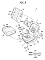
- FIG. 1 is an exploded perspective view illustrating a vehicle seat 1.
- the vehicle seat 1 includes a seat cushion 2 for receiving buttocks of an occupant, and a backrest 3 disposed in an upright state in a rear end of the seat cushion 2.
- the seat cushion 2 is connected to a floor of a vehicle via a front-and-rear position adjusting mechanism and a height adjusting mechanism.
- a front-and-rear position of the seat cushion 2 is adjusted by the position adjusting mechanism, and a height of the seat cushion 2 is adjusted by the height adjusting mechanism.
- Well-known units can be used for the position adjusting mechanism and the height adjusting mechanism.
- the backrest 3 is connected to the rear end of the seat cushion 2 via a reclining mechanism.
- the reclining mechanism adjusts an angle of the backrest 3 with respect to the seat cushion 2.
- the backrest 3 inclines backwardly and rises forwardly by the reclining mechanism, and the reclining mechanism locks the backrest 3.
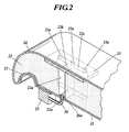
- FIG. 2 is a perspective sectional view illustrating the seat cushion 2 in the state of cutting the seat cushion 2.
- the seat cushion 2 includes a frame 27, a pad 22 disposed on the frame 27, a lining material 21 as a base member for the pad 22, a cover 23 disposed on the pad 22, a top cover member 24 for covering the pad 22 together with the cover 23, and a duct 26 and a blower 25 disposed below the frame 27.
- the frame 27 constitutes a bone structure of the seat cushion 2, and made of, for example, metal.
- a spring is disposed in the frame 27, and the pad 22 is mounted on the frame 27 and the spring.
- the pad 22 is made of a polyurethane foam material, and formed by foaming.
- the lining material 21 is stuck to a lower surface of the pad 22.
- the lining material 21 is integrated with the pad 22.
- a foam resin raw material is supplied to the mold to be foamed and cured.
- the pad 22 is formed and the lining material 21 is integrated with the pad 22.
- the lining material 21 is felt, press-felt, wool, or unwoven cloth.
- the press-felt disclosed in Japanese Patent Application Laid-Open No. 2005-18530 is used as the lining material 21.
- the air permeability of the lining material 21 is preferably low.
- an air guide hole 22a is formed into an H slit shape.
- the air guide hole 22a penetrates the pad 22 from the upper surface to the lower surface.
- a position of the air guide hole 22a is preferably set such that a middle of the air guide hole 22a in a left-and-right direction is a middle of the pad 22 in a left-and-right direction.
- FIG. 3 is a plan view illustrating the air guide hole 22a in the upper surface of the pad 22 as viewed in a penetrating direction of the air guide hole 22a.
- This air guide hole 22a includes a lateral belt portion 22b extending in a left-and-right direction, and a pair of longitudinal belt portions 22c and 22c extending in the front-and-rear direction at both ends of the lateral belt portion 22b.
- a width Wl of the lateral belt portion 22b is preferably set to 10 to 30 mm, more preferably 20 mm.
- a width W2 of the longitudinal belt portion 22c is preferably set to 10 to 30 mm, more preferably 20 mm.
- the lateral belt portion 22b intersects the longitudinal belt portions 22c and 22c at the both ends thereof. Thereby, intersections 22d and 22d are formed. Because the air guide hole 22a is formed in the H slit shape, the air guide hole 22a in the upper surface of the pad 22 is formed in a concaved polygonal, and includes reentrant corners 22e, 22e, 22e and 22e. Since the lateral belt portion 22b intersects the longitudinal belt portions 22c and 22c, a wall surface of the air guide hole 22a forms external corners 22f, 22f, 22f, and 22f.
- the pad 22 includes a protruded portion 22h protruded from the front side toward the rear side of the air guide hole 22a and a protruded portion 22h protruded from the rear side toward the front side of the air guide hole 22a, respectively.
- the lateral belt portion 22b extends in a left-and-right direction between the protruded portions 22h and 22h.
- the air guide hole 22a is blocked by the lining material 21, because the lining material 21 is disposed in the lower surface of the pad 22.
- an inlet hole 21a penetrates the lining material 21 up and down.
- the inlet hole 21a communicates with the lateral belt portion 22b, and a left-and-right position of the inlet hole 21a is in a middle of the lateral belt portion 22b in a left-and-right direction.
- a concaved portion 22d is formed in the upper surface of the pad 22.
- the air guide hole 22a is formed in a bottom of the concaved portion 22d.
- a cover 23 made of a slab polyurethane foam material is fitted to the concaved portion 22d to block the air guide hole 22a from above by the cover 23.
- a surface of the cover 23 and the upper surface of the pad 22 form the same surface.
- a plurality of outlet holes 23a, 23a, ... are formed in the cover 23. These outlet holes 23a, 23a, ... penetrate the cover 23 up and down.
- the outlet holes 23a, 23a, ... are arrayed back and forth in two rows.
- the outlet holes 23a, 23a, ... of one row are arrayed along one longitudinal belt portion 22c to penetrate the cover 23 at one longitudinal belt portion 22c.
- the outlet holes 23a, 23a, ... of the other row are arrayed along the other longitudinal belt portion 22c to penetrate the cover 23 at the other longitudinal belt portion 22c.
- the outlet holes may be formed in the cover 23 between both rows to communicate with the lateral belt portion 22b.
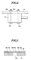
- FIG. 4 is a side view illustrating a fixing structure of the blower 25.
- the blower 25 is fixed to a lower surface of the frame 27 by bolts 25a and nuts 25b.
- One end of the duct 26 is connected to the blower 25, and the other end of the duct 26 is connected to the inlet hole 21a.
- a flange 26a is formed at the other end of the duct 26, the other end of the duct 26 is fitted in the inlet hole 21a, and the flange 26a is hooked on an upper surface of the lining material 21 around the inlet hole 21a.
- a position of disposing the blower 25 is preferably in the front portion or the rear portion of the frame 27. If the blower 25 is disposed in the middle of the frame 27, the middle of the frame 27 is deformed most when an occupant sits on the seat cushion 2.
- FIG. 5 is a sectional view illustrating the top cover member 24 and the cover 23.
- a plurality of microholes 24a are formed in the top cover member 24. These microholes 24a are formed by punching. Because many microholes 24a are distributed in the top cover member 24, some of them overlap the outlet holes 23a and exhaustion is carried out through the outlet holes 23a and the microholes 24a. When the top cover member 24 is highly permeable, there is no need to form microholes 24a in the top cover member 24.
- the air guide hole 22a is formed in the pad 22, the inlet hole 21a formed in the lining material 21 communicates with the air guide hole 22a, and the plurality of outlet holes 23a formed in the cover 23 communicate with the air guide hole 22a.
- the air guide hole 22a functions as a duct. Because the air guide hole 22a functioning as a duct is formed in the pad 22, it is not required that the duct 26 is branched. As a result, the duct 26 can be miniaturized.
- One blower 25 can be shared for the plurality of outlet holes 23a.
- the air guide hole 22a is disposed in symmetrical fashion.
- the inlet hole 21 communicates with the center of the air guide hole 22a.
- a plurality of output holes 23a, 23a, ... are arrayed in two rows.
- the outlet holes 23a of one row are symmetrical to the outlet holes 23a of the other row. Thus, air is uniformly blown out from the outlet holes 23a, 23a, ...
- the air guide hole 22a is formed into the H slit shape by combining a plurality of belt portions.
- the buttocks or the thigh of the seated occupant does not sink in the air guide hole 22a.
- the buttocks or the thigh of the occupant abuts on the protruded portions 22h or the external corners 22f around the intersections 22d to be supported by the protruded portions 22h or the external corners 22f, and the lateral belt portion 22b and the longitudinal belt portions 22c are elongated.
- the air guide hole 22a is formed into not a simple linear slit shape but the H slit shape.
- the air guide hole 22a reaches a wide range of the upper surface of the pad 22. As a result, air is blown out to a wide range of the buttocks or the thigh of the occupant.
- FIG. 6 is a perspective sectional view illustrating the backrest 3 in the state of cutting the backrest 3.
- a pad 32 is disposed on a frame 37 of the backrest 3.
- a lining material 31 is stuck to a back of the pad 32, and the pad 32 is formed by foaming.
- the lining material 31 and the pad 32 are integrated.
- An inlet hole 31a is formed in a center of the lining material 31.
- a concaved portion 32d is formed in a front surface of the pad 32, and an air guide hole 32a is formed in a bottom of the concaved portion 32d.
- the air guide hole 32a penetrates from the bottom of the concaved portion 32d to a rear surface of the pad 32.
- the air guide hole 32a is formed into an H slit shape.
- the air guide hole 32a includes a lateral belt portion 32b extending in a left-and-right direction, and a pair of longitudinal belt portions 32c and 32c extending up and down in both ends of the lateral belt portion 32b. Because the air guide hole 32a is formed in the H slit shape, as in the case of the air guide hole 22a, intersections 32b are formed between the lateral belt portion 32b and the longitudinal belt portions 32c. Further, external corners 32f are formed by a wall surface of the air guide hole 32a, and the air guide hole 32a in the front surface of the pad 32 has a reentrant corner 32e.
- the pad 32 includes a protruded portion 32h protruded from the upper portion toward the lower portion of the air guide hole 32a and a protruded portion 32h protruded from lower portion toward the upper portion of the air guide hole 32a.
- a middle of the air guide hole 32a in a left-and-right direction is preferably a middle of the pad 32 in a left-and-right direction.
- a rear opening of the air guide hole 32a is blocked by the lining material 31.
- the inlet hole 31a formed in the lining material 31 communicates with the air guide hole 32a in a center of the lateral belt portion 32b.
- a cover 33 made of a slab polyurethane foam material is fitted to the concaved portion 32d, and a front opening of the air guide hole 32a is blocked by the cover 33.
- a surface of the cover 33 and the front surface of the pad 32 form the same surface.
- a plurality of outlet holes 33a, 33a, ... are formed in the cover 33.
- the outlet holes 33a, 33a, ... are arrayed up and down in two rows.
- the outlet holes 33a, 33a, ... of one row are arrayed along one longitudinal belt portion 32c to penetrate the cover 33 at one longitudinal belt portion 32c.
- the outlet holes 33a, 33a, ... of the other row are arrayed along the other longitudinal belt portion 32c to penetrate the cover 33 at the other longitudinal belt portion 32c.
- a blower 35 is fixed to a back surface of the frame 37.
- One end of the duct 36 is connected to the blower 35.
- the other end of the duct 36 is fitted in the inlet hole 31a, and a flange 36a of the other end is hooked in a front surface of the frame 37 around the inlet hole 31a.
- the blower 35 is preferably disposed on the lower portion of the frame 37. If the blower 35 is disposed in a middle of the frame 37, the middle of the frame 37 is deformed most when the occupant leans on the backrest 3. If the blower 35 is disposed on the upper portion of the frame 37, the blower 35 becomes obtrusive to an occupant behind the seat 1.
- the top cover member 34 covers the cover 33 and the pad 32 from above the cover 33.
- the top cover member 34 includes a plurality of microholes 34a formed by punching. Some of these microholes 34a overlap the outlet holes 33a, and exhaustion is carried out through the outlet holes 33a and the microholes 34a. If the top cover member 34 is highly permeable, there is no need to form microholes 34a in the top cover member 34.
- the air guide holes 22a and 32a are formed into the H slit shapes.
- other shapes may be employed by combining and communicating a plurality of belt portions with one another.
- the air guide holes 22a and 32a may be formed into E, F, I, M, N, T, U, V, W, X, Y, Z or horseshoe slit shapes.
- the air guide holes having any shapes are used, the air guide holes 22a and 32a can reach wide ranges of the pads 22 and 32, and the back or the buttocks of the seated occupant can be prevented from sinking in the air guide holes 22a and 32a.
- the directions of these character shapes are not limited. However, these shapes are directed so as to be symmetrical.
- a plurality of outlet holes 23a and 33a are preferably arrayed along the shapes of the air guide holes 22a and 32a, and more preferably the outlet holes 23a and 33a are arrayed so as to be symmetrical.
- the inlet holes 21a and 31a are more preferably formed in the lining materials 21 and 31 at the middle portions of the air guide holes 22a and 32a in the left-and-right direction.
- FIG. 7 is a plan view illustrating an air guide hole 51 having a U slit shape as viewed in a penetrating direction of the air guide hole 51.
- the air guide hole 51 includes a pair of longitudinal belt portions 51a and 51a, and a bent portion 51b connected with the end of each of the longitudinal belt portions 51a and 51a.
- the pads 22 and 32 includes protruded portions 52 protruded from one side of the air guide hole 51 toward the opposite side.
- FIG. 8 is a plan view illustrating an air guide hole 61 having a horseshoe slit shape as viewed in a penetrating direction of the air guide hole 61.
- the air guide hole 61 includes a pair of longitudinal belt portions 61a and 61a, and a lateral belt portion 62b connected with the end of each of the longitudinal belt portions 61a and 61a. Since the end of each of the longitudinal belt portions 61a are connected with both ends of the lateral belt portion 62b, the connected portions form bent portions 61c.
- the air guide hole 61 is formed in a horseshoe slit shape, the air guide hole 61 includes reentrant corners 61d and 61d, and external corners 61e and 61e are formed by a wall surface of the air guide hole 61.
- the pads 22 and 32 include protruded portions 62 protruded from one side of the air guide hole 61 toward the opposite side.
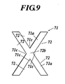
- FIG. 9 is a plan view illustrating an air guide hole 71 having an X slit shape as viewed in a penetrating direction of the air guide hole 71.
- the air guide hole 71 includes oblique belt portions 71a and 71a intersecting each other.
- external corners 71c, 71c, 71c and 71c are formed by a wall surface of the air guide hole 71.
- the air guide hole 71 includes reentrant corners at the external corners 71c.
- blowers 25 and 35 and the ducts 26 and 36 are disposed.
- outlets of an in-room air conditioner of an automobile may be connected with the inlet holes 21a and 31a by a duct to allow air blown from the in-room air conditioner to flow through the duct into the inlet holes 21a and 31a.
- the blowers 25 and 35 may be directly connected to the inlet holes 21a and 31a to directly send air from the blowers 25 and 35 to the inlet holes 21a and 31a.
- the seat according to the present invention is applied to the vehicle seat of the automobile.
- the seat may be applied to seats of other types of vehicles (e.g., airplane and ship).
- the seat of the invention may be applied to other than vehicles.
- the air guide holes 22a and 32a are blocked by the lining materials 21 and 31. However, these holes may be blocked by the frames 27 and 37.
- inlet holes are formed in the frames 27 and 37.
- the frames 27 and 37 are base members.
- forming positions of the inlet holes 21a and 31a have been described.
- forming positions of the inlet holes 21a and 31a are not limited to those of the embodiment. In view of uniform air blowing, forming positions of the inlet holes 21a and 31a, which are described in the embodiment, are preferable.
- a backrest of a seat comprises:
- the air guide hole comprises one of a curved portion, a bent portion and an intersection portion.
- a profile of the air guide hole on the front surface of the pad comprises a reentrant corner.
- a wall surface of the air guide hole forms an external corner.
- the pad comprises a protruded portion protruded from one side of the air guide hole toward an opposite side of the air guide hole as viewed in a penetrating direction of the air guide hole.
- the air guide hole is symmetrical.
- a seat cushion comprises:
- the air guide hole comprises one of a curved portion, a bent portion and an intersection portion.
- a profile of the air guide hole on the upper surface of the pad comprising a reentrant corner.
- a wall surface of the air guide hole forms an external corner.
- the pad comprises a protruded portion protruded from one side of the air guide hole toward an opposite side of the air guide hole as viewed in a penetrating direction of the air guide hole.
- the air guide hole is symmetrical.
- a seat comprises:
- a seat comprises:
- the air guide hole is formed in the pad and the plurality of outlet holes are formed in the cover for blocking the air guide hole, the air guide hole functions as a duct. Air blown into the inlet hole is blown out from each of the outlet holes. Thus, there is no need to dispose any large duct in the backrest or the seat cushion, and one blowing source can be shared for the plurality of outlet holes.
Abstract
A backrest (3) of a seat includes: a pad (32) including a slit air guide hole (32a) which penetrates the pad from a front surface of the pad to a rear surface of the pad; a base member (31) for blocking the air guide hole (32a) on a rear side of the pad (32), the base member (31) including an inlet hole (31a) communicated with the air guide hole (32a); and a cover (33) for blocking the air guide hole (32a) on the front surface of the pad (32), the cover (33) including a plurality of outlet holes (33a) communicated with the air guide hole (32a).
Description
- The present invention relates to a seat, a seat cushion and a backrest thereof, and more particularly to a seat having a ventilating function, and a seat cushion and a backrest thereof.
- Recently, a vehicular seat which has a function of blowing air out of a surface of a seat cushion for receiving buttocks of an occupant or out of a surface of a backrest for receiving a back of the occupant, has been known. As described in Japanese Patent Application Laid-Open No.
2005-287532 - However, because one blower is shared for the plurality of blowout holes, it is necessary that the duct should communicate with these blowout holes. Consequently, it is required to form the duct so as to be branched or to be enlarged.
- An object of the present invention is to dispense with the duct or to miniaturize the duct.
- In accordance with a first aspect of the invention, a backrest of a seat comprises:
- a pad comprising an air guide hole which penetrates the pad from a front surface of the pad to a rear surface of the pad;
- a base member for blocking the air guide hole on a rear side of the pad, the base member comprising an inlet hole communicated with the air guide hole; and
- a cover for blocking the air guide hole on the front surface of the pad, the cover comprising a plurality of outlet holes communicated with the air guide hole.
- In accordance with a second aspect of the invention, a seat cushion comprises:
- a pad comprising an air guide hole which penetrates the pad from an upper surface of the pad to a lower surface of the pad;
- a base member for blocking the air guide hole on a lower side of the pad, the base member comprising an inlet hole communicated with the air guide hole; and
- a cover for blocking the air guide hole on the upper surface of the pad, the cover comprising a plurality of outlet holes communicated with the air guide hole.
- In accordance with a third aspect of the invention, a seat comprises: a seat cushion; and the backrest as defined in the first aspect, the backrest being upright from a rear end of the seat cushion.
- In accordance with a fourth aspect of the invention, a seat comprises:
- the seat cushion as defined in the second aspect; and
- a backrest which is upright from a rear end of the seat cushion.
- The present invention will become fully understood from the detailed description given hereinafter and accompanying drawings given by way of illustration only, and thus are not intended as a definition of the limits of the present invention, and wherein:
-
FIG. 1 is an exploded perspective view illustrating a vehicle seat according to an embodiment of the present invention; -
FIG. 2 is a perspective view illustrating a seat cushion - of the vehicle seat in the state of cutting the seat cushion along the longitudinal section;
-
FIG. 3 is a plan view illustrating an air guide hole formed in a pad of the seat cushion; -
FIG. 4 is a side view illustrating a blower fixing structure of the seat cushion; -
FIG. 5 is a sectional view illustrating a cover and a top cover member of the seat cushion; -
FIG. 6 is a perspective view illustrating a backrest of the vehicle seat in the state of cutting the backrest along the longitudinal section; -
FIG. 7 is a plan view illustrating an air guide hole having another shape; -
FIG. 8 is a plan view illustrating an air guide hole having another shape; and -
FIG. 9 is a plan view illustrating an air guide hole having another shape. - The preferred embodiment of the present invention will be described below referring to the drawings. A variety of technically desirable limitations are added to the embodiment. However, a scope of the present invention is not limited to the embodiment.
-
FIG. 1 is an exploded perspective view illustrating avehicle seat 1. - As shown in
FIG. 1 , thevehicle seat 1 includes aseat cushion 2 for receiving buttocks of an occupant, and a backrest 3 disposed in an upright state in a rear end of theseat cushion 2. - The
seat cushion 2 is connected to a floor of a vehicle via a front-and-rear position adjusting mechanism and a height adjusting mechanism. A front-and-rear position of theseat cushion 2 is adjusted by the position adjusting mechanism, and a height of theseat cushion 2 is adjusted by the height adjusting mechanism. Well-known units can be used for the position adjusting mechanism and the height adjusting mechanism. - The backrest 3 is connected to the rear end of the
seat cushion 2 via a reclining mechanism. The reclining mechanism adjusts an angle of the backrest 3 with respect to theseat cushion 2. The backrest 3 inclines backwardly and rises forwardly by the reclining mechanism, and the reclining mechanism locks the backrest 3. -
FIG. 2 is a perspective sectional view illustrating theseat cushion 2 in the state of cutting theseat cushion 2. - As shown in
FIGS. 1 and2 , theseat cushion 2 includes aframe 27, apad 22 disposed on theframe 27, alining material 21 as a base member for thepad 22, acover 23 disposed on thepad 22, atop cover member 24 for covering thepad 22 together with thecover 23, and aduct 26 and ablower 25 disposed below theframe 27. - The
frame 27 constitutes a bone structure of theseat cushion 2, and made of, for example, metal. A spring is disposed in theframe 27, and thepad 22 is mounted on theframe 27 and the spring. - The
pad 22 is made of a polyurethane foam material, and formed by foaming. Thelining material 21 is stuck to a lower surface of thepad 22. Thelining material 21 is integrated with thepad 22. Specifically, in a state of setting thelining material 21 in a mold, a foam resin raw material is supplied to the mold to be foamed and cured. Thereby, thepad 22 is formed and thelining material 21 is integrated with thepad 22. Thelining material 21 is felt, press-felt, wool, or unwoven cloth. For example, the press-felt disclosed in Japanese Patent Application Laid-Open No.2005-18530 lining material 21. The air permeability of thelining material 21 is preferably low. - In the
pad 22, anair guide hole 22a is formed into an H slit shape. Theair guide hole 22a penetrates thepad 22 from the upper surface to the lower surface. A position of theair guide hole 22a is preferably set such that a middle of theair guide hole 22a in a left-and-right direction is a middle of thepad 22 in a left-and-right direction. -
FIG. 3 is a plan view illustrating theair guide hole 22a in the upper surface of thepad 22 as viewed in a penetrating direction of theair guide hole 22a. Thisair guide hole 22a includes alateral belt portion 22b extending in a left-and-right direction, and a pair oflongitudinal belt portions lateral belt portion 22b. A width Wl of thelateral belt portion 22b is preferably set to 10 to 30 mm, more preferably 20 mm. A width W2 of thelongitudinal belt portion 22c is preferably set to 10 to 30 mm, more preferably 20 mm. - The
lateral belt portion 22b intersects thelongitudinal belt portions intersections air guide hole 22a is formed in the H slit shape, theair guide hole 22a in the upper surface of thepad 22 is formed in a concaved polygonal, and includesreentrant corners lateral belt portion 22b intersects thelongitudinal belt portions air guide hole 22a formsexternal corners air guide hole 22a is formed in the H slit shape, thepad 22 includes a protrudedportion 22h protruded from the front side toward the rear side of theair guide hole 22a and a protrudedportion 22h protruded from the rear side toward the front side of theair guide hole 22a, respectively. Thelateral belt portion 22b extends in a left-and-right direction between theprotruded portions - The
air guide hole 22a is blocked by the liningmaterial 21, because thelining material 21 is disposed in the lower surface of thepad 22. At the center of thelining material 21, aninlet hole 21a penetrates the liningmaterial 21 up and down. Thus, theinlet hole 21a communicates with thelateral belt portion 22b, and a left-and-right position of theinlet hole 21a is in a middle of thelateral belt portion 22b in a left-and-right direction. - A
concaved portion 22d is formed in the upper surface of thepad 22. Theair guide hole 22a is formed in a bottom of theconcaved portion 22d. Acover 23 made of a slab polyurethane foam material is fitted to theconcaved portion 22d to block theair guide hole 22a from above by thecover 23. A surface of thecover 23 and the upper surface of thepad 22 form the same surface. - A plurality of
outlet holes cover 23. These outlet holes 23a, 23a, ... penetrate thecover 23 up and down. The outlet holes 23a, 23a, ... are arrayed back and forth in two rows. The outlet holes 23a, 23a, ... of one row are arrayed along onelongitudinal belt portion 22c to penetrate thecover 23 at onelongitudinal belt portion 22c. The outlet holes 23a, 23a, ... of the other row are arrayed along the otherlongitudinal belt portion 22c to penetrate thecover 23 at the otherlongitudinal belt portion 22c. The outlet holes may be formed in thecover 23 between both rows to communicate with thelateral belt portion 22b. -
FIG. 4 is a side view illustrating a fixing structure of theblower 25. As shown inFIGS. 1 ,2 and4 , theblower 25 is fixed to a lower surface of theframe 27 bybolts 25a and nuts 25b. One end of theduct 26 is connected to theblower 25, and the other end of theduct 26 is connected to theinlet hole 21a. Aflange 26a is formed at the other end of theduct 26, the other end of theduct 26 is fitted in theinlet hole 21a, and theflange 26a is hooked on an upper surface of thelining material 21 around theinlet hole 21a. A position of disposing theblower 25 is preferably in the front portion or the rear portion of theframe 27. If theblower 25 is disposed in the middle of theframe 27, the middle of theframe 27 is deformed most when an occupant sits on theseat cushion 2. - As shown in
FIGS. 1 and2 , thetop cover member 24 covers thecover 23 and thepad 22 from above thecover 23.FIG. 5 is a sectional view illustrating thetop cover member 24 and thecover 23. As shown inFIGS. 1 and5 , a plurality ofmicroholes 24a are formed in thetop cover member 24. Thesemicroholes 24a are formed by punching. Becausemany microholes 24a are distributed in thetop cover member 24, some of them overlap the outlet holes 23a and exhaustion is carried out through the outlet holes 23a and themicroholes 24a. When thetop cover member 24 is highly permeable, there is no need to formmicroholes 24a in thetop cover member 24. - In the
seat cushion 2, when theblower 25 is actuated, air is sent by theblower 25 through theduct 26 to theinlet hole 21a. The air sent to theinlet hole 21a is blown out through theoutlet holes microholes 24a. - As described above, the
air guide hole 22a is formed in thepad 22, theinlet hole 21a formed in thelining material 21 communicates with theair guide hole 22a, and the plurality ofoutlet holes 23a formed in thecover 23 communicate with theair guide hole 22a. Thus, theair guide hole 22a functions as a duct. Because theair guide hole 22a functioning as a duct is formed in thepad 22, it is not required that theduct 26 is branched. As a result, theduct 26 can be miniaturized. Oneblower 25 can be shared for the plurality ofoutlet holes 23a. - The
air guide hole 22a is disposed in symmetrical fashion. Theinlet hole 21 communicates with the center of theair guide hole 22a. A plurality ofoutput holes outlet holes - The
air guide hole 22a is formed into the H slit shape by combining a plurality of belt portions. Thus, the buttocks or the thigh of the seated occupant does not sink in theair guide hole 22a. In other words, the buttocks or the thigh of the occupant abuts on the protrudedportions 22h or theexternal corners 22f around theintersections 22d to be supported by the protrudedportions 22h or theexternal corners 22f, and thelateral belt portion 22b and thelongitudinal belt portions 22c are elongated. Thus, the buttocks or the thigh of the occupant does not sink in theair guide hole 22a. Theair guide hole 22a is formed into not a simple linear slit shape but the H slit shape. Thus, even though an area of theair guide hole 22a itself is small, theair guide hole 22a reaches a wide range of the upper surface of thepad 22. As a result, air is blown out to a wide range of the buttocks or the thigh of the occupant. - The backrest 3 will be explained referring to
FIGS. 1 and6. FIG. 6 is a perspective sectional view illustrating the backrest 3 in the state of cutting the backrest 3. - As shown in
FIGS. 1 and6 , apad 32 is disposed on aframe 37 of the backrest 3. A liningmaterial 31 is stuck to a back of thepad 32, and thepad 32 is formed by foaming. Thus, the liningmaterial 31 and thepad 32 are integrated. Aninlet hole 31a is formed in a center of thelining material 31. Aconcaved portion 32d is formed in a front surface of thepad 32, and anair guide hole 32a is formed in a bottom of theconcaved portion 32d. Theair guide hole 32a penetrates from the bottom of theconcaved portion 32d to a rear surface of thepad 32. Theair guide hole 32a is formed into an H slit shape. In other words, theair guide hole 32a includes alateral belt portion 32b extending in a left-and-right direction, and a pair oflongitudinal belt portions lateral belt portion 32b. Because theair guide hole 32a is formed in the H slit shape, as in the case of theair guide hole 22a,intersections 32b are formed between thelateral belt portion 32b and thelongitudinal belt portions 32c. Further,external corners 32f are formed by a wall surface of theair guide hole 32a, and theair guide hole 32a in the front surface of thepad 32 has areentrant corner 32e. Thepad 32 includes a protrudedportion 32h protruded from the upper portion toward the lower portion of theair guide hole 32a and a protrudedportion 32h protruded from lower portion toward the upper portion of theair guide hole 32a. - Regarding to a position of disposing the
air guide hole 32a, a middle of theair guide hole 32a in a left-and-right direction is preferably a middle of thepad 32 in a left-and-right direction. A rear opening of theair guide hole 32a is blocked by the liningmaterial 31. Theinlet hole 31a formed in thelining material 31 communicates with theair guide hole 32a in a center of thelateral belt portion 32b. - A
cover 33 made of a slab polyurethane foam material is fitted to theconcaved portion 32d, and a front opening of theair guide hole 32a is blocked by thecover 33. A surface of thecover 33 and the front surface of thepad 32 form the same surface. - A plurality of
outlet holes cover 33. The outlet holes 33a, 33a, ... are arrayed up and down in two rows. The outlet holes 33a, 33a, ... of one row are arrayed along onelongitudinal belt portion 32c to penetrate thecover 33 at onelongitudinal belt portion 32c. The outlet holes 33a, 33a, ... of the other row are arrayed along the otherlongitudinal belt portion 32c to penetrate thecover 33 at the otherlongitudinal belt portion 32c. - A
blower 35 is fixed to a back surface of theframe 37. One end of theduct 36 is connected to theblower 35. The other end of theduct 36 is fitted in theinlet hole 31a, and aflange 36a of the other end is hooked in a front surface of theframe 37 around theinlet hole 31a. Theblower 35 is preferably disposed on the lower portion of theframe 37. If theblower 35 is disposed in a middle of theframe 37, the middle of theframe 37 is deformed most when the occupant leans on the backrest 3. If theblower 35 is disposed on the upper portion of theframe 37, theblower 35 becomes obtrusive to an occupant behind theseat 1. - The
top cover member 34 covers thecover 33 and thepad 32 from above thecover 33. Thetop cover member 34 includes a plurality ofmicroholes 34a formed by punching. Some of thesemicroholes 34a overlap theoutlet holes 33a, and exhaustion is carried out through the outlet holes 33a and themicroholes 34a. If thetop cover member 34 is highly permeable, there is no need to formmicroholes 34a in thetop cover member 34. - In the backrest 3, when the
blower 35 is actuated, air is sent by theblower 35 through theduct 36 to theinlet hole 31a. Then, the air sent to theinlet hole 31a is blown out through theoutlet holes microholes 34a. - The air guide holes 22a and 32a are formed into the H slit shapes. However, other shapes may be employed by combining and communicating a plurality of belt portions with one another. For example, the air guide holes 22a and 32a may be formed into E, F, I, M, N, T, U, V, W, X, Y, Z or horseshoe slit shapes. Even though the air guide holes having any shapes are used, the air guide holes 22a and 32a can reach wide ranges of the
pads outlet holes lining materials -
FIG. 7 is a plan view illustrating anair guide hole 51 having a U slit shape as viewed in a penetrating direction of theair guide hole 51. - As shown in
FIG. 7 , theair guide hole 51 includes a pair oflongitudinal belt portions bent portion 51b connected with the end of each of thelongitudinal belt portions pads pads portions 52 protruded from one side of theair guide hole 51 toward the opposite side. -
FIG. 8 is a plan view illustrating anair guide hole 61 having a horseshoe slit shape as viewed in a penetrating direction of theair guide hole 61. - As shown in
FIG. 8 , theair guide hole 61 includes a pair oflongitudinal belt portions longitudinal belt portions longitudinal belt portions 61a are connected with both ends of the lateral belt portion 62b, the connected portions formbent portions 61c. Theair guide hole 61 is formed in a horseshoe slit shape, theair guide hole 61 includesreentrant corners external corners air guide hole 61. When the air guide holes 61 penetrate thepads pads portions 62 protruded from one side of theair guide hole 61 toward the opposite side. -
FIG. 9 is a plan view illustrating anair guide hole 71 having an X slit shape as viewed in a penetrating direction of theair guide hole 71. - As shown in
FIG. 9 , theair guide hole 71 includesoblique belt portions intersection 72b between thebelt portions external corners air guide hole 71. Theair guide hole 71 includes reentrant corners at theexternal corners 71c. When the air guide holes 71 penetrate thepads pads air guide hole 71 toward the opposite side respectively. - The present invention is not limited to the above-described embodiment. Various changes and modifications can appropriately be made without departing from the gist of the present invention.
- For example, it is not required that the
blowers ducts - Without disposing any
ducts blowers blowers - In the above-described embodiment, the seat according to the present invention is applied to the vehicle seat of the automobile. However, the seat may be applied to seats of other types of vehicles (e.g., airplane and ship). The seat of the invention may be applied to other than vehicles.
- According to the above-described embodiment, the air guide holes 22a and 32a are blocked by the
lining materials frames frames frames frames - In the above-described embodiment, more preferable forming positions of the inlet holes 21a and 31a have been described. However, as long as the
inlet hole 21a communicates with theair guide hole 22a and theinlet hole 31a communicates with theair guide hole 32a, forming positions of the inlet holes 21a and 31a are not limited to those of the embodiment. In view of uniform air blowing, forming positions of the inlet holes 21a and 31a, which are described in the embodiment, are preferable. - In accordance with a first aspect of the preferred embodiment of the present invention, a backrest of a seat comprises:
- a pad comprising an air guide hole which penetrates the pad from a front surface of the pad to a rear surface of the pad;
- a base member for blocking the air guide hole on a rear side of the pad, the base member comprising an inlet hole communicated with the air guide hole; and
- a cover for blocking the air guide hole on the front surface of the pad, the cover comprising a plurality of outlet holes communicated with the air guide hole.
- Preferably, the air guide hole comprises one of a curved portion, a bent portion and an intersection portion.
- Preferably, a profile of the air guide hole on the front surface of the pad comprises a reentrant corner.
- Preferably, a wall surface of the air guide hole forms an external corner.
- Preferably, the pad comprises a protruded portion protruded from one side of the air guide hole toward an opposite side of the air guide hole as viewed in a penetrating direction of the air guide hole.
- Preferably, the air guide hole is symmetrical.
- In accordance with a second aspect of the preferred embodiment of the present invention, a seat cushion comprises:
- a pad comprising an air guide hole which penetrates the pad from an upper surface of the pad to a lower surface of the pad;
- a base member for blocking the air guide hole on a lower side of the pad, the base member comprising an inlet hole communicated with the air guide hole; and
- a cover for blocking the air guide hole on the upper surface of the pad, the cover comprising a plurality of outlet holes communicated with the air guide hole.
- Preferably, the air guide hole comprises one of a curved portion, a bent portion and an intersection portion.
- Preferably, a profile of the air guide hole on the upper surface of the pad comprising a reentrant corner.
- Preferably, a wall surface of the air guide hole forms an external corner.
- Preferably, the pad comprises a protruded portion protruded from one side of the air guide hole toward an opposite side of the air guide hole as viewed in a penetrating direction of the air guide hole.
- Preferably, the air guide hole is symmetrical.
- In accordance with a third aspect of the preferred embodiment of the present invention, a seat comprises:
- a seat cushion; and
- the backrest as defined in the first aspect, the backrest being upright from a rear end of the seat cushion.
- In accordance with a fourth aspect of the preferred embodiment of the present invention, a seat comprises:
- the seat cushion as defined in the second aspect; and
- a backrest which is upright from a rear end of the seat cushion.
- According to the first to fourth aspects of the preferred embodiments of the present invention, because the air guide hole is formed in the pad and the plurality of outlet holes are formed in the cover for blocking the air guide hole, the air guide hole functions as a duct. Air blown into the inlet hole is blown out from each of the outlet holes. Thus, there is no need to dispose any large duct in the backrest or the seat cushion, and one blowing source can be shared for the plurality of outlet holes.
- By the above preferable shape of the air guide hole, it is possible to prevent buttocks or a back of an occupant from falling into the air guide hole.
- The entire disclosure of a Japanese Patent Application No.
2007-265574, filed on October 11, 2007
Claims (14)
- A backrest of a seat comprising:a pad comprising an air guide hole which penetrates the pad from a front surface of the pad to a rear surface of the pad;a base member for blocking the air guide hole on a rear side of the pad, the base member comprising an inlet hole communicated with the air guide hole; anda cover for blocking the air guide hole on the front surface of the pad, the cover comprising a plurality of outlet holes communicated with the air guide hole.
- The backrest as claimed in claim 1,
wherein the air guide hole comprises one of a curved portion, a bent portion and an intersection portion. - The backrest as claimed in claim 1,
wherein a profile of the air guide hole on the front surface of the pad comprises a reentrant corner. - The backrest as claimed in claim 1,
wherein a wall surface of the air guide hole forms an external corner. - The backrest as claimed in claim 1,
wherein the pad comprises a protruded portion protruded from one side of the air guide hole toward an opposite side of the air guide hole as viewed in a penetrating direction of the air guide hole. - The backrest of the seat as claimed in claim 1,
wherein the air guide hole is symmetrical. - A seat cushion comprising:a pad comprising an air guide hole which penetrates the pad from an upper surface of the pad to a lower surface of the pad ;a base member for blocking the air guide hole on a lower side of the pad, the base member comprising an inlet hole communicated with the air guide hole; anda cover for blocking the air guide hole on the upper surface of the pad, the cover comprising a plurality of outlet holes communicated with the air guide hole.
- The seat cushion as claimed in claim 7,
wherein the air guide hole comprises one of a curved portion, a bent portion and an intersection portion. - The seat cushion as claimed in claim 7,
wherein a profile of the air guide hole on the upper surface of the pad comprising a reentrant corner. - The seat cushion as claimed in claim 7,
wherein a wall surface of the air guide hole forms an external corner. - The seat cushion as claimed in claim 7,
wherein the pad comprises a protruded portion protruded from one side of the air guide hole toward an opposite side of the air guide hole as viewed in a penetrating direction of the air guide hole. - The seat cushion as claimed in claim 7, wherein the air guide hole is symmetrical.
- A seat comprising:a seat cushion; andthe backrest as claimed in claim 1, the backrest being upright from a rear end of the seat cushion.
- A seat comprising:the seat cushion as claimed in claim 7; anda backrest which is upright from a rear end of the seat cushion.
Applications Claiming Priority (1)
| Application Number | Priority Date | Filing Date | Title |
|---|---|---|---|
| JP2007265574A JP2009090016A (en) | 2007-10-11 | 2007-10-11 | Seat, seat cushion and backrest thereof |
Publications (1)
| Publication Number | Publication Date |
|---|---|
| EP2048024A1 true EP2048024A1 (en) | 2009-04-15 |
Family
ID=40263118
Family Applications (1)
| Application Number | Title | Priority Date | Filing Date |
|---|---|---|---|
| EP08253311A Withdrawn EP2048024A1 (en) | 2007-10-11 | 2008-10-10 | Seat, seat cushion and backrest thereof |
Country Status (4)
| Country | Link |
|---|---|
| US (1) | US7857395B2 (en) |
| EP (1) | EP2048024A1 (en) |
| JP (1) | JP2009090016A (en) |
| CN (1) | CN101406351A (en) |
Families Citing this family (28)
| Publication number | Priority date | Publication date | Assignee | Title |
|---|---|---|---|---|
| JP5251018B2 (en) * | 2007-07-04 | 2013-07-31 | トヨタ紡織株式会社 | Breathable cushion and method for manufacturing the same |
| US20110221242A1 (en) * | 2007-10-29 | 2011-09-15 | W.E.T. Automotive Systems Ag | Air conditioning device for seats |
| JP4499167B2 (en) * | 2008-03-31 | 2010-07-07 | 本田技研工業株式会社 | Temperature control sheet |
| DE202009017049U1 (en) * | 2008-12-21 | 2010-05-12 | W.E.T. Automotive Systems Ag | aerator |
| JP5050032B2 (en) * | 2009-10-16 | 2012-10-17 | ブリヂストンサイクル株式会社 | Cushion, child seat device and motorcycle |
| JP5556156B2 (en) * | 2009-12-08 | 2014-07-23 | トヨタ紡織株式会社 | Vehicle seat |
| JP5591059B2 (en) * | 2010-10-14 | 2014-09-17 | 株式会社イノアックコーポレーション | Ducted seat pad and manufacturing method thereof |
| JP2012218655A (en) * | 2011-04-13 | 2012-11-12 | Nissan Motor Co Ltd | Vehicle seat |
| JP2013023003A (en) * | 2011-07-19 | 2013-02-04 | Toyota Boshoku Corp | Vehicle seat |
| US9738191B2 (en) * | 2012-10-11 | 2017-08-22 | Kongsberg Automotive, Inc. | Ventilated and heated vehicle seat assembly |
| US9168852B2 (en) | 2012-12-03 | 2015-10-27 | Ford Global Technologies, Llc | Climate comfort seat assembly |
| KR101528583B1 (en) * | 2012-12-31 | 2015-06-15 | 갑을오토텍(주) | Car seat having channe |
| JP2014172511A (en) * | 2013-03-08 | 2014-09-22 | Denso Corp | Fitting structure of occupant seating detecting load detector |
| JP6094323B2 (en) * | 2013-03-29 | 2017-03-15 | トヨタ紡織株式会社 | Vehicle seat |
| CN104207521B (en) * | 2013-06-03 | 2018-09-18 | 陶伟龙 | A kind of general seat unit of multinomial healthy functions |
| WO2015030195A1 (en) | 2013-08-30 | 2015-03-05 | テイ・エス テック株式会社 | Seat |
| JP6305780B2 (en) * | 2014-02-04 | 2018-04-04 | 美津濃株式会社 | Vehicle seat |
| US9746190B2 (en) * | 2014-06-06 | 2017-08-29 | Intellihot, Inc. | Combined heating system capable of bi-directional heating |
| JP6288851B2 (en) * | 2014-08-06 | 2018-03-07 | 株式会社タチエス | Breathable sheet and sheet air conditioning system |
| US10384575B2 (en) | 2014-10-28 | 2019-08-20 | Gentherm Automotive Systems (China) Ltd. | Lumbar spacer |
| WO2017011990A1 (en) | 2015-07-21 | 2017-01-26 | Gentherm Automotive Systems (China) Ltd. | Connector for a climate controlled support device |
| JP6639926B2 (en) * | 2016-01-25 | 2020-02-05 | 株式会社イノアックコーポレーション | Vehicle seat pad and method of manufacturing the same |
| US11135949B2 (en) * | 2016-09-30 | 2021-10-05 | Ts Tech Co., Ltd. | Seat with blower |
| KR20180037679A (en) * | 2016-10-05 | 2018-04-13 | 현대자동차주식회사 | Ventilation seat for vehicle |
| JP6652199B2 (en) * | 2016-10-24 | 2020-02-19 | 株式会社デンソー | Ventilation seat and seat air conditioner |
| KR20200033578A (en) * | 2018-09-20 | 2020-03-30 | 현대트랜시스 주식회사 | Ventilation seat for vehicle |
| USD889154S1 (en) * | 2018-12-04 | 2020-07-07 | Spec Seats Technologies Inc. | Seat and back cushions for a chair |
| KR102597544B1 (en) * | 2021-04-02 | 2023-11-03 | 주식회사 디에스시동탄 | Support driver and support assembly including the same |
Citations (10)
| Publication number | Priority date | Publication date | Assignee | Title |
|---|---|---|---|---|
| WO2002053400A2 (en) * | 2001-01-05 | 2002-07-11 | Johnson Controls Technology Company | Air distribution system for ventilated seat |
| US6481801B1 (en) * | 1999-09-21 | 2002-11-19 | Johnson Controls Technology Company | Seat paddings for vehicle seats |
| US20040090093A1 (en) * | 2002-11-13 | 2004-05-13 | Toshifumi Kamiya | Vehicle seat air conditioning system |
| US20040139758A1 (en) * | 2003-01-14 | 2004-07-22 | Toshifumi Kamiya | Seat air conditioner for vehicle and seat structure |
| JP2005018530A (en) | 2003-06-27 | 2005-01-20 | Toshiba Corp | Information processor, information processing program, and information processing method |
| JP2005287532A (en) | 2004-03-31 | 2005-10-20 | T S Tec Kk | Car seat |
| US20050264086A1 (en) * | 2004-05-25 | 2005-12-01 | John Lofy | Climate controlled seat |
| WO2006102509A1 (en) * | 2005-03-23 | 2006-09-28 | Amerigon, Inc. | Vehicle seat with thermal elements |
| US20070040421A1 (en) * | 2005-08-22 | 2007-02-22 | Lear Corporation | Seat assembly having an air plenum member |
| JP2007265574A (en) | 2006-03-29 | 2007-10-11 | Fujifilm Corp | Magnetic recording medium |
Family Cites Families (30)
| Publication number | Priority date | Publication date | Assignee | Title |
|---|---|---|---|---|
| US3550523A (en) | 1969-05-12 | 1970-12-29 | Irving Segal | Seat construction for automotive air conditioning |
| DE2510182C3 (en) | 1975-03-08 | 1980-06-26 | Walter 4018 Langenfeld Ismer | Seat and back cushions, in particular for vehicle seats |
| JPS63149333A (en) | 1986-12-15 | 1988-06-22 | Nkk Corp | Coating method for powdery coke on green pellet for burnt agglomerated ore |
| US5226188A (en) * | 1992-06-26 | 1993-07-13 | Liou Yaw Tyng | Ventilated foam cushion |
| JPH0648448A (en) | 1992-07-20 | 1994-02-22 | Adoheya Sansho Kk | Envelope and sealing thereof |
| US5597200A (en) | 1993-11-22 | 1997-01-28 | Amerigon, Inc. | Variable temperature seat |
| SE504973C2 (en) | 1995-09-14 | 1997-06-02 | Walinov Ab | Fan unit included in a ventilated vehicle seat |
| US5645314A (en) * | 1995-09-21 | 1997-07-08 | Liou; Yaw-Tyng | Ventilation cushion for chairs |
| US5749111A (en) | 1996-02-14 | 1998-05-12 | Teksource, Lc | Gelatinous cushions with buckling columns |
| JP3666774B2 (en) | 1997-04-09 | 2005-06-29 | 本田技研工業株式会社 | Automotive seat structure |
| JP3705395B2 (en) | 1997-04-22 | 2005-10-12 | 本田技研工業株式会社 | Automotive seat structure |
| US5927817A (en) * | 1997-08-27 | 1999-07-27 | Lear Corporation | Ventilated vehicle seat assembly |
| DE19745521C2 (en) | 1997-10-15 | 2001-12-13 | Daimler Chrysler Ag | Upholstery for a vehicle seat |
| JPH11123124A (en) | 1997-10-21 | 1999-05-11 | Ts Tec Kk | Air-permeable seat |
| US6179706B1 (en) | 1998-06-19 | 2001-01-30 | Denso Corporation | Seat air conditioner for vehicle |
| DE19847384C1 (en) | 1998-10-14 | 2000-06-21 | Daimler Chrysler Ag | Upholstery for seat part and / or backrest of a vehicle seat |
| JP2001047848A (en) | 1999-08-03 | 2001-02-20 | Denso Corp | Air conditioner for vehicular seat |
| FR2815901B1 (en) | 2000-10-31 | 2003-08-08 | Faurecia Sieges Automobile | UPHOLSTERED ELEMENT FOR VEHICLE AND MANUFACTURING METHOD THEREOF |
| JP3861674B2 (en) | 2001-11-30 | 2006-12-20 | 株式会社デンソー | Vehicle seat air conditioner and air conditioner built-in vehicle seat |
| JP2003235676A (en) * | 2002-02-18 | 2003-08-26 | Daihatsu Motor Co Ltd | Seat structure for vehicle |
| JP2003235677A (en) * | 2002-02-19 | 2003-08-26 | Daihatsu Motor Co Ltd | Temperature control seat |
| JP3804566B2 (en) | 2002-03-28 | 2006-08-02 | 株式会社デンソー | Vehicle seat air conditioner |
| JP3835329B2 (en) | 2002-03-28 | 2006-10-18 | 株式会社デンソー | Vehicle seat air conditioner |
| JP4062952B2 (en) | 2002-04-09 | 2008-03-19 | 松下電器産業株式会社 | Air-conditioning seat device |
| JP2004073429A (en) * | 2002-08-15 | 2004-03-11 | Nhk Spring Co Ltd | Air permeable seat |
| JP2004082960A (en) | 2002-08-28 | 2004-03-18 | Johnson Controls Automotive Systems Corp | Seat for vehicle |
| US6857697B2 (en) | 2002-08-29 | 2005-02-22 | W.E.T. Automotive Systems Ag | Automotive vehicle seating comfort system |
| JP4347646B2 (en) * | 2003-09-24 | 2009-10-21 | 東洋ゴム工業株式会社 | Cushion pad |
| CA2558828C (en) * | 2004-03-31 | 2012-01-24 | Shinya Ishima | Vehicle seat |
| US20080073966A1 (en) * | 2006-08-30 | 2008-03-27 | Lear Corporation | Vehicle seat assembly having a hardness gradient via hollowed sections and/or protrusions |
-
2007
- 2007-10-11 JP JP2007265574A patent/JP2009090016A/en active Pending
-
2008
- 2008-10-03 US US12/285,411 patent/US7857395B2/en active Active
- 2008-10-10 EP EP08253311A patent/EP2048024A1/en not_active Withdrawn
- 2008-10-13 CN CN200810170177.0A patent/CN101406351A/en active Pending
Patent Citations (10)
| Publication number | Priority date | Publication date | Assignee | Title |
|---|---|---|---|---|
| US6481801B1 (en) * | 1999-09-21 | 2002-11-19 | Johnson Controls Technology Company | Seat paddings for vehicle seats |
| WO2002053400A2 (en) * | 2001-01-05 | 2002-07-11 | Johnson Controls Technology Company | Air distribution system for ventilated seat |
| US20040090093A1 (en) * | 2002-11-13 | 2004-05-13 | Toshifumi Kamiya | Vehicle seat air conditioning system |
| US20040139758A1 (en) * | 2003-01-14 | 2004-07-22 | Toshifumi Kamiya | Seat air conditioner for vehicle and seat structure |
| JP2005018530A (en) | 2003-06-27 | 2005-01-20 | Toshiba Corp | Information processor, information processing program, and information processing method |
| JP2005287532A (en) | 2004-03-31 | 2005-10-20 | T S Tec Kk | Car seat |
| US20050264086A1 (en) * | 2004-05-25 | 2005-12-01 | John Lofy | Climate controlled seat |
| WO2006102509A1 (en) * | 2005-03-23 | 2006-09-28 | Amerigon, Inc. | Vehicle seat with thermal elements |
| US20070040421A1 (en) * | 2005-08-22 | 2007-02-22 | Lear Corporation | Seat assembly having an air plenum member |
| JP2007265574A (en) | 2006-03-29 | 2007-10-11 | Fujifilm Corp | Magnetic recording medium |
Also Published As
| Publication number | Publication date |
|---|---|
| US7857395B2 (en) | 2010-12-28 |
| CN101406351A (en) | 2009-04-15 |
| US20090096256A1 (en) | 2009-04-16 |
| JP2009090016A (en) | 2009-04-30 |
Similar Documents
| Publication | Publication Date | Title |
|---|---|---|
| US7857395B2 (en) | Seat, seat cushion and backrest thereof | |
| US7229129B2 (en) | Ventilated seat | |
| US6145925A (en) | Backrest for vehicle seats | |
| US7533941B2 (en) | Seat pad for vehicle | |
| EP1007386B1 (en) | Ventilated vehicle seat assembly | |
| US6546578B1 (en) | Seat cushion for vehicle seats | |
| JP4013765B2 (en) | Vehicle seat air conditioner | |
| US11932141B2 (en) | Vehicle seat | |
| US20050280294A1 (en) | Vehicle seat | |
| CN110267848A (en) | Seat for vehicle | |
| JP5377895B2 (en) | Vehicle seat provided with a ventilation device | |
| JP2005287537A (en) | Car seat | |
| EP1050429A3 (en) | Vehicle seat | |
| CN109641545B (en) | Arrangement structure for arranging sensor to seat | |
| JP2013255829A (en) | Seat | |
| JP2007084039A (en) | Seat pad for vehicle | |
| JP2007215695A (en) | Vehicle seat | |
| WO2004020231A1 (en) | Seat for vehcile | |
| US10604041B2 (en) | Vehicle seating cushion with lines to interconnect with line detents on a structural support | |
| JP6597589B2 (en) | Sheet | |
| JP6067789B2 (en) | Sheet | |
| JP6930289B2 (en) | Seat | |
| US20230271536A1 (en) | Ventilated seat and method of making | |
| JP2024033228A (en) | vehicle seat | |
| JP2019147513A (en) | Seat pad and seat |
Legal Events
| Date | Code | Title | Description |
|---|---|---|---|
| PUAI | Public reference made under article 153(3) epc to a published international application that has entered the european phase |
Free format text: ORIGINAL CODE: 0009012 |
|
| AK | Designated contracting states |
Kind code of ref document: A1 Designated state(s): AT BE BG CH CY CZ DE DK EE ES FI FR GB GR HR HU IE IS IT LI LT LU LV MC MT NL NO PL PT RO SE SI SK TR |
|
| AX | Request for extension of the european patent |
Extension state: AL BA MK RS |
|
| AKX | Designation fees paid | ||
| REG | Reference to a national code |
Ref country code: DE Ref legal event code: 8566 |
|
| STAA | Information on the status of an ep patent application or granted ep patent |
Free format text: STATUS: THE APPLICATION IS DEEMED TO BE WITHDRAWN |
|
| 18D | Application deemed to be withdrawn |
Effective date: 20091016 |