EP2042829A1 - Modular calibration - Google Patents
Modular calibration Download PDFInfo
- Publication number
- EP2042829A1 EP2042829A1 EP08102554A EP08102554A EP2042829A1 EP 2042829 A1 EP2042829 A1 EP 2042829A1 EP 08102554 A EP08102554 A EP 08102554A EP 08102554 A EP08102554 A EP 08102554A EP 2042829 A1 EP2042829 A1 EP 2042829A1
- Authority
- EP
- European Patent Office
- Prior art keywords
- calibration
- previous
- component
- cmm
- measuring system
- Prior art date
- Legal status (The legal status is an assumption and is not a legal conclusion. Google has not performed a legal analysis and makes no representation as to the accuracy of the status listed.)
- Granted
Links
- 238000000034 method Methods 0.000 claims abstract description 45
- 239000011159 matrix material Substances 0.000 claims description 11
- 238000004590 computer program Methods 0.000 claims description 3
- 238000013507 mapping Methods 0.000 abstract description 15
- 239000000523 sample Substances 0.000 description 27
- 230000006870 function Effects 0.000 description 5
- 238000013519 translation Methods 0.000 description 5
- 238000010586 diagram Methods 0.000 description 4
- 238000005259 measurement Methods 0.000 description 4
- 241001422033 Thestylus Species 0.000 description 3
- 238000012937 correction Methods 0.000 description 3
- 238000004519 manufacturing process Methods 0.000 description 3
- 230000003068 static effect Effects 0.000 description 3
- 230000001133 acceleration Effects 0.000 description 2
- 238000013459 approach Methods 0.000 description 2
- 238000005452 bending Methods 0.000 description 2
- 238000006073 displacement reaction Methods 0.000 description 2
- 230000000694 effects Effects 0.000 description 2
- 238000007781 pre-processing Methods 0.000 description 2
- 238000012360 testing method Methods 0.000 description 2
- 210000000707 wrist Anatomy 0.000 description 2
- 230000006399 behavior Effects 0.000 description 1
- 238000004364 calculation method Methods 0.000 description 1
- 238000000354 decomposition reaction Methods 0.000 description 1
- 238000007689 inspection Methods 0.000 description 1
- 238000007620 mathematical function Methods 0.000 description 1
- 230000003287 optical effect Effects 0.000 description 1
- 230000008520 organization Effects 0.000 description 1
- 238000012216 screening Methods 0.000 description 1
- 230000011218 segmentation Effects 0.000 description 1
- 238000012956 testing procedure Methods 0.000 description 1
- 238000012546 transfer Methods 0.000 description 1
- 239000013598 vector Substances 0.000 description 1
Images


Classifications
-
- G—PHYSICS
- G01—MEASURING; TESTING
- G01B—MEASURING LENGTH, THICKNESS OR SIMILAR LINEAR DIMENSIONS; MEASURING ANGLES; MEASURING AREAS; MEASURING IRREGULARITIES OF SURFACES OR CONTOURS
- G01B21/00—Measuring arrangements or details thereof, where the measuring technique is not covered by the other groups of this subclass, unspecified or not relevant
- G01B21/02—Measuring arrangements or details thereof, where the measuring technique is not covered by the other groups of this subclass, unspecified or not relevant for measuring length, width, or thickness
- G01B21/04—Measuring arrangements or details thereof, where the measuring technique is not covered by the other groups of this subclass, unspecified or not relevant for measuring length, width, or thickness by measuring coordinates of points
- G01B21/042—Calibration or calibration artifacts
Definitions
- the present invention relates to a calibration method for a coordinate measuring machine (CMM), and a computer-readable medium therefore.
- CCM coordinate measuring machine
- Calibration methods are meant to ensure the accuracy of measurement tools by providing a preliminary reliability check.
- calibration consists in comparing measurement outputs to known references values. When discrepancies are noticed between the two sets of values, an error correction is carried out, so that the actual measured value and the known theoretical values are aligned.
- the calibration step is usually performed prior to the first use of a system, in order to make sure that it is delivers the right values when used. It can be then repeated at major overhauls.
- CMM systems In the CMM domain, machines usually have at least three degrees of freedom (a.k.a. DOF). Systems with six or more DOF are however known. CMM systems usually comprise a support moving linearly according to the three axis of space X, Y, Z and a stylus of lighter weight attached to it, that is moveable in rotation, for example by the interposition of an articulated probe head.
- the most common calibration processes consists in measuring coordinates over a so-called calibration artefact that is typically a sphere so that all the degrees of freedom can be simultaneously tested, i.e. as well the position and the orientation over the full range of operation of the machine.
- CMM systems offer a selection of measuring probes, which can be connected to the positioning head, and are specialized to the execution of different measurement tasks.
- a CMM could be fitted, for example, with a selection of trigger touch probes of different length and shapes, scanning probes, contactless probes, optical inspection probes, and so on. Each individual probe requires an individual and separate calibration.
- a new probe head is introduced in the system, or whenever an element of the cinematic chain of the CMM is altered, all the probes ought to be individually recalibrated to ensure optimal precision.
- the need of frequent calibration is a drawback for the user of the CMM, in that it reduces the availability of the CMM system. Furthermore, the management of the calibration data for each probe is a burden to the user of the CMM.
- Another issue for ensuring the precision of the calibration is to include dynamic and bending parameters, in order to know how the system reacts to forces applied on the stylus and what the influences of forces of inertia are. To this effect, it is known to include, in the calibration process, measurements of the displacement of the CMM probe as a function of the contact force, for example.
- a first model presented in US5594668 , takes into account elastic properties of a probe and derives distortions due to acceleration through matrix calculations. Similarly in WO2006/114603 an inertia matrix is used and deflection forces are taken into account. Yet in both case the intrinsic elastic properties of the probe used are not derived from a preliminary calibration step, but are hard-coded based on manufacturer data, so that the precision is not individually adapted to each device.
- US20020087233 describes a modular portable CMM with interchangeable probes, in which an EEPROM circuit board contains calibration and identification data for avoiding unit mix-up; nevertheless those data are not derived from any calibration operation on the probes themselves and hence do not contain any probe-specific data.
- the present invention is based on the recognition of the above shortcoming of the prior art, and aims to overcome them.
- the present invention proposes a method to reduce the impact of the calibrations on the availability of a CMM system, and to lessen the burden of managing a large set of calibration data, so that the ease of use is improved.
- the accuracy is improved as well since the calibration steps prior to the mounting of the machine are not generic for a given component type or model any more, but derive specific characteristics of each tested component.
- such preliminary calibration steps are carried out prior to the step of mounting said CMM . and, preferably, parts of said components are individually calibrated for each degree of freedom of said components and yield specific mapping information.
- the mapping information is then stored, after map files have been generated and associated to the calibrated components.
- a final alignment step take place after said CMM is mounted. It just processes and aligns the mapping information gathered during the preliminary calibration steps.
- each position of the calibration probe can be obtained by several configurations of the CMM, each requiring a separate calibration. Due to the time-consuming character of the optimisation process in order to ensure the best accurate tuning, usually only a limited number of points in the configuration space of the machines are calibrated, and calibration data relative to the remaining configuration are obtained by interpolation. The sparseness of the calibration points limits the precision of this technique.
- the modular calibration method according to the invention is meant to improve the accuracy of the machine calibration settings while providing single individual calibrations of components prior to the mounting of the probe, and using this information once the machine is mounted.
- This way, the complex optimisation problem is split into single optimisation problems that can better be handled with specific quality machines for each component, e.g. at their own production site.
- the calibration procedure on the mounted CMM, consisting in aligning all available calibration information gathered in the previous individual calibration procedures is thus much simpler.
- the use of specific tailored calibration information yielded by individual testing procedures for each component allows to improve the overall calibration accuracy, since the calibration can cover optimally the configuration space of each single component; on the other hand, it provides more scalability and improved availability of the system, because a component swap or exchange is possible without needing to go through an overall calibration procedure again.
- a CMM system is considered as a combination of simple components, for example a moving platform in a XYZ three-dimensional reference, an orientable probe head having one or two rotation axes, probes and accessories, like touch trigger probes, styli, and lengthening elements, out of a set of compatible interchangeable elements.
- Some of the components are active elements, corresponding to degrees of freedom in the CMM system and include preferably, for each DOF, an actuator to set the DOF and an encoder to read its position out.
- the CMM system can be decomposed in an ensemble of single components, which define a complex cinematic chain.
- a CMM measuring system fitted with a rotary head and a touch probe, as shown in example figure 4 could be formally decomposed into:a linear actuator and encoder corresponding to the translation along the horizontal "Y" axis;
- each elementary subsystem a)-f) determines the coordinate and the orientation of the sensed point.
- Each one of those subsystems has a specific orientation in a relative reference.
- the presented example shows, for the sake of simplicity, a cinematic serial chain, i.e. a chain of actuators which are connected one after the other.
- the invention is not limited to this case, and also comprises the case of parallel actuators, like for example a six-axis Stewart platform.
- the presented CMM system comprises, beyond the three-axis XYZ actuators, a plurality of modular components, for example the rotary head 132 and the stylus 135.
- the CMM system can be fitted, with a combination of components chosen from a modular set.
- the decomposition of the cinematic chain in subsystem can correspond to a detachable or modular component of the overall system, but this is in no way a requirement of the invention.
- the rotary head 132 for example is decomposed in two independent elementary systems, corresponding to its independent degrees of freedom. As mentioned in the introduction, the calibration of such a complex measuring machine is time-consuming and delicate, and must be repeated every time the machine's configuration is altered.
- a global calibration can be obtained by composition of the individual calibrations.
- the configuration of the CMM system is fully determined by a set of parameters, including, for example, displacements and rotation angles relative to the various degrees of freedom, plus eventually the temperature and other global parameters.
- This is obtained, in a conventional way, by measuring a set of reference points, or the surface of a reference object, and by known numeric error minimization techniques.
- the present invention deals with a process of constructing a global calibration M , by a set of subsystem calibration.
- the submaps M j may depend of one or more parameters of the machine to qualify each component relatively to the reference space of the CMM, each default can induce relative reference changes in the cinematic chain.
- the calibration needs not be limited to a static correspondence, put also include dynamic effect, thus introducing a dependence from velocities ⁇ , accelerations ⁇ , and the masses of the various elements.
- the global calibration function can be computed, from single calibrations of the subsystems.
- Fig. 1 illustrates the overall concept of the invention through a sequence diagram of a preferred embodiment.
- the two dotted boxes 100 and 700 stand respectively for the set of steps taking place before the CMM is mounted and after the CMM is mounted
- the dotted arrows 900 stand for a mutual information exchange between those two sets of steps, since the step or steps after the mounting use information precisely provided by the steps prior to the mounting.
- the sequence of steps unfolds as follows:
- Fig. 2 illustrates in more detail the steps prior to the mounting of the CMM according to a preferred embodiment of the invention.
- the subsystems 10 of the CMM system which are further referenced according to letters A, B, C, D etc. organized in rows to distinguish between them, are preferably tested by a corresponding specialized equipment in production 14 (step 200).
- the calibration operation provides specific calibration data (step 300) for each subsystem or component.
- the calibration information can span different parameters, possibly depending on the component. It is usually distinguished between geometrical mapping, where the encoders associated to either of the 6 degrees of freedom of the machine derive the position, and stiffness mapping, where an encoder derives a position shift based on a force applied due to some bending of a component. Dynamic mapping can also be applied to a CMM in deriving a position shift based on inertia forces applied to the CMM.
- step 400 it is precisely the goal of the gathering and organization step (step 400) to group the information of the map files into map sets 18 (illustrated later on Fig.2 ) which are structured so that the final alignment procedure is simplified as much as possible through such pre-processing.
- An adequate segmentation and presentation of the calibration information further allows to perform the final alignment procedure in a modular fashion, the user being able to select what needs to be aligned and what doesn't. He can e.g. decide whether if any further mapping like stiffness or dynamic mapping should be done on top of the basic geometrical mapping.
- Logical calibration information maps 19 can hence be formed and stored into a set of maps 18 (step 500), from which the user will select the sets or subsets of his choice, as shown on Fig.2 .
- the map files generated by the preliminary calibration steps 100 and associated to the subsystems are organized into matrix.
- the combination of each specific subsystem matrix of a component define a component matrix.
- Each entries of the component matrix define a reference orientation, linear parameters, rotational parameters and some others parameters such as the ones previously listed above (degrees of Freedom, stiffness mapping, dynamic mapping, this list not trying to be exhaustive).
- the component matrix can be optimized to define mathematical functions depending of the complexity of the component. They define exactly the dynamic behaviour of the component for each position. To gain time, single subsystem matrix is more accurate and easier to recalibrate.
- the semi-automatic alignment step provided by the modular calibration method of the invention will allow the user to choose to which elements or part of the element (subsystem) the alignment will be applied, as well as which parameters will come into play at that stage.
- the information maps can be designed in a modular mode so that it takes into account only selected elements of the matrix.
- the storing process depends to some extent on the data representation and associated pre-processing strategy adopted for building the information maps based on the map files, there are also different strategies for the physical storing if the information.
- the storage of the information is done locally on each component itself. An auto-discovery feature during the mounting step could then allow to detect and fetch the files corresponding to each component so that those files can be processed during the alignment procedure.
- the storing step can also be performed on a remote storage device, like e.g. a central database, from which as well rough map files and information map sets could be selectively or automatically downloaded in the frame of the alignment step.
- Fig. 3 shows a logical view of a physical system according to a preferred embodiment for the invention, comprising a CMM 90 and a controller for the CMM 15, linked by a physical input/output (I/O) connection.
- the CMM comprises a plurality of subsystems 10 distinguished by the letters (A), (B), and (C) arranged in columns and, to which position transducers 12 are coupled for the geometrical mapping and optionally sensors 13, e.g. strain gauges or touch trigger switches, are also coupled.
- the link between the CMM subsystems and the sensors has been drawn in dotted lines to represent that not all subsytems need be associated with a sensor 13.
- the invention is not limited to the calibration of active elements including position transducers 12 and, indeed, some of the simplest subsystems 10, may be, for example, passive extension elements, without transducers or actuators.
- a data transfer link for example a connection bus 11, is also provided.
- the CMM controller 15 comprises a processor 16 for carrying out the alignment step, and a memory or storage device 17 for providing all the necessary calibration information to be processed.
- the memory contains individual map files 20 (A), (B), (C) etc. associated to each respective component 10 (A), (B), (C), etc.
- the association between the map files 20 and the components should be, however, understood as a logical link, not limitative in terms of physical implementation options. Indeed, many physical embodiments are possible for the storage, as well as for the recognition and retrieval of the associated file.
- a computer program can for example be provided with an autodiscovery function for detecting the components and/or retrieve map files 20 before the alignment step is carried out. This can be e.g. through a polling functionality in charge of periodically screening if calibration files are available.
- Such an autodiscovery function can be associated as well with a tool-changer module (not shown) in order to determine which tools are actually present on the machine, based on port number information.
Abstract
Description
- The present invention relates to a calibration method for a coordinate measuring machine (CMM), and a computer-readable medium therefore.
- Calibration methods are meant to ensure the accuracy of measurement tools by providing a preliminary reliability check. Generally speaking, calibration consists in comparing measurement outputs to known references values. When discrepancies are noticed between the two sets of values, an error correction is carried out, so that the actual measured value and the known theoretical values are aligned. The calibration step is usually performed prior to the first use of a system, in order to make sure that it is delivers the right values when used. It can be then repeated at major overhauls.
- In the CMM domain, machines usually have at least three degrees of freedom (a.k.a. DOF). Systems with six or more DOF are however known. CMM systems usually comprise a support moving linearly according to the three axis of space X, Y, Z and a stylus of lighter weight attached to it, that is moveable in rotation, for example by the interposition of an articulated probe head. The most common calibration processes consists in measuring coordinates over a so-called calibration artefact that is typically a sphere so that all the degrees of freedom can be simultaneously tested, i.e. as well the position and the orientation over the full range of operation of the machine.
- In general, CMM systems offer a selection of measuring probes, which can be connected to the positioning head, and are specialized to the execution of different measurement tasks. A CMM could be fitted, for example, with a selection of trigger touch probes of different length and shapes, scanning probes, contactless probes, optical inspection probes, and so on. Each individual probe requires an individual and separate calibration. On the other hand, when a new probe head is introduced in the system, or whenever an element of the cinematic chain of the CMM is altered, all the probes ought to be individually recalibrated to ensure optimal precision.
- The need of frequent calibration is a drawback for the user of the CMM, in that it reduces the availability of the CMM system. Furthermore, the management of the calibration data for each probe is a burden to the user of the CMM.
- Another drawback of the calibration processes known from the art is that the calibration is done only on a discrete number of selected positions, so that the accuracy optimisation is not guaranteed for all positions. Furthermore, since the full global calibration operation always takes place on mounted machines, it is always difficult to identify the right sources of the major deviations since there is no way to distinguish between parameters at this stage a priori, so that the parameter weighting and adjustment is quite time-consuming.
- Another issue for ensuring the precision of the calibration is to include dynamic and bending parameters, in order to know how the system reacts to forces applied on the stylus and what the influences of forces of inertia are. To this effect, it is known to include, in the calibration process, measurements of the displacement of the CMM probe as a function of the contact force, for example.
- Many numeric models have been developed for error correction in order to improve the accuracy of the calibration systems. A first model, presented in
US5594668 , takes into account elastic properties of a probe and derives distortions due to acceleration through matrix calculations. Similarly inWO2006/114603 an inertia matrix is used and deflection forces are taken into account. Yet in both case the intrinsic elastic properties of the probe used are not derived from a preliminary calibration step, but are hard-coded based on manufacturer data, so that the precision is not individually adapted to each device. -
US20020087233 describes a modular portable CMM with interchangeable probes, in which an EEPROM circuit board contains calibration and identification data for avoiding unit mix-up; nevertheless those data are not derived from any calibration operation on the probes themselves and hence do not contain any probe-specific data. - The present invention is based on the recognition of the above shortcoming of the prior art, and aims to overcome them. In particular the present invention proposes a method to reduce the impact of the calibrations on the availability of a CMM system, and to lessen the burden of managing a large set of calibration data, so that the ease of use is improved. The accuracy is improved as well since the calibration steps prior to the mounting of the machine are not generic for a given component type or model any more, but derive specific characteristics of each tested component.
- According to the invention, these aims are achieved by means of a modular calibration method for a CMM, which comprises a plurality of components, where preliminary calibration steps take place according to the appended claims.
- In preferred embodiments such preliminary calibration steps are carried out prior to the step of mounting said CMM . and, preferably, parts of said components are individually calibrated for each degree of freedom of said components and yield specific mapping information. The mapping information is then stored, after map files have been generated and associated to the calibrated components. A final alignment step take place after said CMM is mounted. It just processes and aligns the mapping information gathered during the preliminary calibration steps.
- Such a modular approach allows to best fit to the actual intrinsic properties of each single component, each single movement and each single degree of freedom in each relative positioning reference. It hence ensures a high quality accuracy since specialized equipment can be used at production site for their calibration. It also shifts the overall optimisation complexity towards single optimisation problems, so that the computation requirements on the mounted machine, which have always been cumbersome and time-consuming, are strongly simplified. Furthermore, such a modular approach is suited for repeated calibration operations when only simple add-ons or piece exchanges need to be carried out.
- The invention will be better understood with the aid of the description of an embodiment given by way of example and illustrated by the figures, in which:
-
Fig. 1 shows a sequence diagram of the calibration steps according to a preferred embodiment of the invention; -
Fig. 2 shows a detailed diagram of the calibration steps prior to the CMM mounting according to a preferred embodiment of the invention; -
Fig 3 shows a logical view of a physical system according to a preferred embodiment for the invention. -
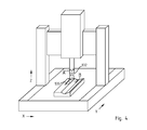
Figure 4 shows a CMM system equipped with a rotary head and a touch probe, used to illustrate the terminology of the description of the invention. - As mentioned earlier, the state of the art calibration methods for
CMMs 90 are known to be cumbersome and time-consuming. Indeed, the calibration process is delicate and long because several calibration parameters have to be adjusted simultaneously. In the general case involving translation and rotation DOF, each position of the calibration probe can be obtained by several configurations of the CMM, each requiring a separate calibration. Due to the time-consuming character of the optimisation process in order to ensure the best accurate tuning, usually only a limited number of points in the configuration space of the machines are calibrated, and calibration data relative to the remaining configuration are obtained by interpolation. The sparseness of the calibration points limits the precision of this technique. - The modular calibration method according to the invention is meant to improve the accuracy of the machine calibration settings while providing single individual calibrations of components prior to the mounting of the probe, and using this information once the machine is mounted. This way, the complex optimisation problem is split into single optimisation problems that can better be handled with specific quality machines for each component, e.g. at their own production site. The calibration procedure on the mounted CMM, consisting in aligning all available calibration information gathered in the previous individual calibration procedures is thus much simpler. On one hand, the use of specific tailored calibration information yielded by individual testing procedures for each component allows to improve the overall calibration accuracy, since the calibration can cover optimally the configuration space of each single component; on the other hand, it provides more scalability and improved availability of the system, because a component swap or exchange is possible without needing to go through an overall calibration procedure again.
- According to one aspect of the invention, a CMM system is considered as a combination of simple components, for example a moving platform in a XYZ three-dimensional reference, an orientable probe head having one or two rotation axes, probes and accessories, like touch trigger probes, styli, and lengthening elements, out of a set of compatible interchangeable elements. Some of the components are active elements, corresponding to degrees of freedom in the CMM system and include preferably, for each DOF, an actuator to set the DOF and an encoder to read its position out.
- In a general way, the CMM system can be decomposed in an ensemble of single components, which define a complex cinematic chain. For example, a CMM measuring system fitted with a rotary head and a touch probe, as shown in example
figure 4 could be formally decomposed into:a linear actuator and encoder corresponding to the translation along the horizontal "Y" axis; - b. a linear actuator and encoder corresponding to the translation along the horizontal "X" axis;
- c. a linear actuator and encoder corresponding to the translation along the vertical "Z" axis;
- d. a rotary actuator and encoder corresponding to the rotation about the vertical "A" axis of the wrist of the probe
- e. a rotary actuator and encoder corresponding to the rotation about the horizontal "B" axis of the wrist of the probe;
- f. a fixed translation corresponding to the
stylus 135 in use - The combination of each elementary subsystem a)-f) determines the coordinate and the orientation of the sensed point. Each one of those subsystems has a specific orientation in a relative reference. The presented example shows, for the sake of simplicity, a cinematic serial chain, i.e. a chain of actuators which are connected one after the other. The invention, however, is not limited to this case, and also comprises the case of parallel actuators, like for example a six-axis Stewart platform.
- The presented CMM system comprises, beyond the three-axis XYZ actuators, a plurality of modular components, for example the
rotary head 132 and thestylus 135. Depending from the task to be performed, the CMM system can be fitted, with a combination of components chosen from a modular set. The decomposition of the cinematic chain in subsystem can correspond to a detachable or modular component of the overall system, but this is in no way a requirement of the invention. Therotary head 132, for example is decomposed in two independent elementary systems, corresponding to its independent degrees of freedom.
As mentioned in the introduction, the calibration of such a complex measuring machine is time-consuming and delicate, and must be repeated every time the machine's configuration is altered. When the measuring system is decomposed in subsystems, however, and each subsystem is individually calibrated, a global calibration can be obtained by composition of the individual calibrations.
Formally, the configuration of the CMM system is fully determined by a set of parameters, including, for example, displacements and rotation angles relative to the various degrees of freedom, plus eventually the temperature and other global parameters. The static calibration of the CMM system can be regarded as a correspondence, or map M,
between the parameter space of the CMM system (whose elements are represented by vectors of parameters= ξ1,ξ2,...ξ n , the values of ξ being usually known from the encoders of the CMM system) and
X the actual position of the measured point, for example in a cartesian coordinate systemX = (x,y,z). This is obtained, in a conventional way, by measuring a set of reference points, or the surface of a reference object, and by known numeric error minimization techniques. The present invention deals with a process of constructing a global calibration M, by a set of subsystem calibration. - In the simple but very common case in which the kinematical chain of the CMM system is fully serial, one can consider each degree of freedom as independent subsystem, and construct M as a composition of correspondences Mj (ξ j ), each one corresponding to a degree of freedom

- In a more general case, the submaps Mj may depend of one or more parameters of the machine to qualify each component relatively to the reference space of the CMM, each default can induce relative reference changes in the cinematic chain. The calibration needs not be limited to a static correspondence, put also include dynamic effect, thus introducing a dependence from velocitiesξ̇, accelerations ξ̈, and the masses of the various elements. In all these cases, the global calibration function can be computed, from single calibrations of the subsystems.
-
Fig. 1 illustrates the overall concept of the invention through a sequence diagram of a preferred embodiment. In the diagram, the two dottedboxes arrows 900 stand for a mutual information exchange between those two sets of steps, since the step or steps after the mounting use information precisely provided by the steps prior to the mounting. The sequence of steps unfolds as follows: - 200: preliminary calibration step of some subsystem or individual components making up the CMM. This individual testing can be carried out off-site with specific equipment in order to ensure a high level of quality for the error correction and compensation;
- 300: as a result of the individual testing processes, calibration information is provided, which is specific to the subsystem or individual component and not generic to all the component of the same model. According to the modular calibration method of the invention, the calibration information relative to different individual components having the same specifications (e.g. two scanning probe of the same model) can thus be different, even if only slightly, which would not be the case if only model-generic information was be stored and attached in a static manner to a piece. The output of this step is to generate a so-called map file which will be associated to the calibrated component;
- According to the needs, the map file of a component can include different calibration data, for example geometric calibration data, or sensivity to deformation induce by some combination of heavy final elements as well as stiffness calibration and dynamic data, by known methods. In the case of an active element, the calibration will include several different configurations of the elements, in order to cover appropriately the element's configuration space;
- 400: once the individual calibration procedures have delivered an output, the yielded calibration information can be further processed and organized according to different criteria that will be discussed based on
figure 2 further in this document; - 500: the storing of calibration information. Different strategies for the storing are possible and are also discussed further in this document based on
Fig. 2 ; - 600: the combination of the elements to provide a working CMM system with a set of desired features. This step could be done manually, for example when fitting a probe on the spindle of a CMM positioning platform, or automatically, for example in the case of a system equipped with an automatic tool-changing magazine;
- 800: the final alignment procedure for mapping and coordinating all the calibration information. In a preferred embodiment of the invention, this step can be fully automatic, i.e. requiring no human intervention. As a result, once the different elements of the CMM are combined together, the system is "auto-calibrated" in the sense that a calibration supervisor detects the components, selects the relevant calibration files, and combines them in a system calibration file. According to another preferred embodiment for the invention, the alignment function can be semi-automatic, as explained later in this document.
-
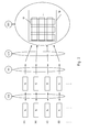
Fig. 2 illustrates in more detail the steps prior to the mounting of the CMM according to a preferred embodiment of the invention. Thesubsystems 10 of the CMM system, which are further referenced according to letters A, B, C, D etc. organized in rows to distinguish between them, are preferably tested by a corresponding specialized equipment in production 14 (step 200). The calibration operation provides specific calibration data (step 300) for each subsystem or component. The calibration information can span different parameters, possibly depending on the component. It is usually distinguished between geometrical mapping, where the encoders associated to either of the 6 degrees of freedom of the machine derive the position, and stiffness mapping, where an encoder derives a position shift based on a force applied due to some bending of a component. Dynamic mapping can also be applied to a CMM in deriving a position shift based on inertia forces applied to the CMM. - It is precisely the goal of the gathering and organization step (step 400) to group the information of the map files into map sets 18 (illustrated later on
Fig.2 ) which are structured so that the final alignment procedure is simplified as much as possible through such pre-processing. An adequate segmentation and presentation of the calibration information further allows to perform the final alignment procedure in a modular fashion, the user being able to select what needs to be aligned and what doesn't. He can e.g. decide whether if any further mapping like stiffness or dynamic mapping should be done on top of the basic geometrical mapping. Logical calibration information maps 19 can hence be formed and stored into a set of maps 18 (step 500), from which the user will select the sets or subsets of his choice, as shown onFig.2 . - According to the preferred embodiment disclosed in
Fig.2 , the map files generated by the preliminary calibration steps 100 and associated to the subsystems are organized into matrix. The combination of each specific subsystem matrix of a component define a component matrix. Each entries of the component matrix define a reference orientation, linear parameters, rotational parameters and some others parameters such as the ones previously listed above (degrees of Freedom, stiffness mapping, dynamic mapping, this list not trying to be exhaustive). The component matrix can be optimized to define mathematical functions depending of the complexity of the component. They define exactly the dynamic behaviour of the component for each position. To gain time, single subsystem matrix is more accurate and easier to recalibrate. As result, the semi-automatic alignment step provided by the modular calibration method of the invention will allow the user to choose to which elements or part of the element (subsystem) the alignment will be applied, as well as which parameters will come into play at that stage. Obviously, the information maps can be designed in a modular mode so that it takes into account only selected elements of the matrix. - Although the storing process depends to some extent on the data representation and associated pre-processing strategy adopted for building the information maps based on the map files, there are also different strategies for the physical storing if the information. According to a preferred embodiment of the invention, the storage of the information is done locally on each component itself. An auto-discovery feature during the mounting step could then allow to detect and fetch the files corresponding to each component so that those files can be processed during the alignment procedure. According to another embodiment, the storing step can also be performed on a remote storage device, like e.g. a central database, from which as well rough map files and information map sets could be selectively or automatically downloaded in the frame of the alignment step.
-
Fig. 3 shows a logical view of a physical system according to a preferred embodiment for the invention, comprising aCMM 90 and a controller for theCMM 15, linked by a physical input/output (I/O) connection. The CMM comprises a plurality ofsubsystems 10 distinguished by the letters (A), (B), and (C) arranged in columns and, to which position transducers 12 are coupled for the geometrical mapping andoptionally sensors 13, e.g. strain gauges or touch trigger switches, are also coupled. The link between the CMM subsystems and the sensors has been drawn in dotted lines to represent that not all subsytems need be associated with asensor 13. The invention, however is not limited to the calibration of active elements includingposition transducers 12 and, indeed, some of thesimplest subsystems 10, may be, for example, passive extension elements, without transducers or actuators. - In order for all elements to communicate among each other, a data transfer link, for example a
connection bus 11, is also provided. - The
CMM controller 15 comprises aprocessor 16 for carrying out the alignment step, and a memory orstorage device 17 for providing all the necessary calibration information to be processed. According to the preferred embodiment ofFig.3 , the memory contains individual map files 20 (A), (B), (C) etc. associated to each respective component 10 (A), (B), (C), etc. The association between the map files 20 and the components should be, however, understood as a logical link, not limitative in terms of physical implementation options. Indeed, many physical embodiments are possible for the storage, as well as for the recognition and retrieval of the associated file. - A computer program can for example be provided with an autodiscovery function for detecting the components and/or retrieve
map files 20 before the alignment step is carried out. This can be e.g. through a polling functionality in charge of periodically screening if calibration files are available. Such an autodiscovery function can be associated as well with a tool-changer module (not shown) in order to determine which tools are actually present on the machine, based on port number information. - Although this invention has been described with reference to CMMs, the scope could be broadened to robotics as well as any other suitable industrial domain for which such a modular calibration method is potentially relevant.
Claims (14)
- A modular calibration method for a coordinate measuring system, said coordinate measuring system comprising a plurality of subsystems, comprising:preliminary calibration steps (100) prior to the step of mounting said CMM, wherein at least part of said subsystems are individually calibrated (200) (off-site) and provide specific calibration information (300) for eachsubsystem, wherein map files (20) are generated and associated to said calibrated subsystem;a step of storing said calibration information (500), anda final alignment step (800), wherein said final alignment step (800) processes said calibration information gathered during said preliminary calibration steps.The method of the previous claim, wherein each subsystem corresponds to a degree of freedom of one element of the coordinate measuring system.
- The method of claim 1, further comprising a step of gathering and organizing said calibration (400) before storing (500) said calibration information.
- The method of claim 1, wherein at least one of said subsystems corresponds to a modular component of said coordinate measuring system.
- The method of any of the previous claims, wherein said storing step is done on separate storage means for each subsystem.
- The method of the previous claim, wherein said storing step (500) is done locally on each component itself.
- The method of one of the claims from 1 to 6, wherein said storing step (500) is done on a remote storage device.
- The method of one of the previous claims, wherein the map files (20) are organized into matrix.
- The method of one of the previous claims, wherein the single map files for each degree of freedom of a component are combined with their own relative positioning reference into a composed and optimized matrix for each component.
- The method of one of the previous claims, wherein the alignment step (800) is automatic.
- The method of one of the previous claims, wherein the alignment step (800) is semi-automatic, a user being able to select a single specific calibration parameter which needs to be done.
- A component of a coordinate measuring system(10), said component being associated to a map file (20) generated and stored according to the method of any of the previous claims.
- A computer program product for carrying out the alignment step (800) of the method according to any of the previous claims.
- A computer program product according to the previous claim, further performing an auto-discovery function for the components and/or map files before said alignment step (800).
- A controller (15) for a coordinate measuring system, comprising a storage device (17) and a processor (16) for carrying out the alignment step (800) according to any of the previous claims.
Priority Applications (1)
| Application Number | Priority Date | Filing Date | Title |
|---|---|---|---|
| EP08102554.6A EP2042829B2 (en) | 2007-09-26 | 2008-03-12 | Modular calibration |
Applications Claiming Priority (2)
| Application Number | Priority Date | Filing Date | Title |
|---|---|---|---|
| EP07117240 | 2007-09-26 | ||
| EP08102554.6A EP2042829B2 (en) | 2007-09-26 | 2008-03-12 | Modular calibration |
Publications (3)
| Publication Number | Publication Date |
|---|---|
| EP2042829A1 true EP2042829A1 (en) | 2009-04-01 |
| EP2042829B1 EP2042829B1 (en) | 2014-01-01 |
| EP2042829B2 EP2042829B2 (en) | 2017-08-09 |
Family
ID=40279134
Family Applications (1)
| Application Number | Title | Priority Date | Filing Date |
|---|---|---|---|
| EP08102554.6A Active EP2042829B2 (en) | 2007-09-26 | 2008-03-12 | Modular calibration |
Country Status (5)
| Country | Link |
|---|---|
| US (1) | US8290733B2 (en) |
| EP (1) | EP2042829B2 (en) |
| JP (1) | JP2009080114A (en) |
| CN (1) | CN101424526B (en) |
| HK (1) | HK1128756A1 (en) |
Cited By (1)
| Publication number | Priority date | Publication date | Assignee | Title |
|---|---|---|---|---|
| CN111895940A (en) * | 2020-04-26 | 2020-11-06 | 鸿富锦精密电子(成都)有限公司 | Calibration file generation method, system, computer device and storage medium |
Families Citing this family (15)
| Publication number | Priority date | Publication date | Assignee | Title |
|---|---|---|---|---|
| JP2010502953A (en) * | 2006-08-31 | 2010-01-28 | ファロ テクノロジーズ インコーポレーテッド | Intelligent probe |
| WO2009001385A1 (en) * | 2007-06-28 | 2008-12-31 | Hexagon Metrology S.P.A. | Method for determining dynamic errors in a measuring machine |
| US7908756B2 (en) * | 2007-10-12 | 2011-03-22 | Los Alamos National Security, Llc | Integrated calibration sphere and calibration step fixture for improved coordinate measurement machine calibration |
| JP5192283B2 (en) * | 2008-05-13 | 2013-05-08 | 株式会社ミツトヨ | CMM |
| EP2184591B1 (en) | 2008-11-05 | 2016-05-25 | VEGA Grieshaber KG | Sensor comprising memory-equipped modules |
| JP5417222B2 (en) * | 2010-03-05 | 2014-02-12 | 株式会社ミツトヨ | Tolerance detection method and apparatus for roundness measuring machine |
| WO2013130991A1 (en) | 2012-03-02 | 2013-09-06 | Hexagon Metrology, Inc. | Coordinate measuring machine with support beam having springs |
| US8817240B2 (en) | 2012-05-25 | 2014-08-26 | Mitutoyo Corporation | Interchangeable optics configuration for a chromatic range sensor optical pen |
| US8736817B2 (en) | 2012-05-25 | 2014-05-27 | Mitutoyo Corporation | Interchangeable chromatic range sensor probe for a coordinate measuring machine |
| FR2997180B1 (en) | 2012-10-24 | 2015-01-16 | Commissariat Energie Atomique | BIDIMENSIONAL METROLOGICAL CALIBRATION |
| US9068822B2 (en) | 2013-07-03 | 2015-06-30 | Mitutoyo Corporation | Chromatic range sensor probe detachment sensor |
| EP3184960B1 (en) * | 2015-12-22 | 2018-06-27 | Tesa Sa | Motorized orientable head for measuring system |
| CN106980099B (en) * | 2017-05-26 | 2019-08-16 | 深圳市赛伦北斗科技有限责任公司 | A kind of calibration method and system of Automatic Testing System of Circuit Board |
| DE102017131066A1 (en) * | 2017-12-22 | 2019-06-27 | Endress+Hauser SE+Co. KG | Method of providing calibrated pressure transducers |
| JP2022186534A (en) * | 2021-06-04 | 2022-12-15 | 株式会社ミツトヨ | Correction method for probe unit |
Citations (5)
| Publication number | Priority date | Publication date | Assignee | Title |
|---|---|---|---|---|
| US5594668A (en) | 1994-10-13 | 1997-01-14 | Carl-Zeiss-Stiftung | Method for correcting coordinate measurement on workpieces based on bending characteristics |
| US20020087233A1 (en) | 1993-02-23 | 2002-07-04 | Simon Raab | Portable coordinate measurement machine with pre-stressed bearings |
| US6668466B1 (en) * | 2000-10-19 | 2003-12-30 | Sandia Corporation | Highly accurate articulated coordinate measuring machine |
| WO2006114603A2 (en) | 2005-04-26 | 2006-11-02 | Renishaw Plc | Probe calibration |
| WO2007097841A2 (en) * | 2006-01-18 | 2007-08-30 | Faro Technologies, Inc. | Portable coordinate measurement machine with integrated line laser scanner |
Family Cites Families (22)
| Publication number | Priority date | Publication date | Assignee | Title |
|---|---|---|---|---|
| DE3150977A1 (en) * | 1981-12-23 | 1983-06-30 | Fa. Carl Zeiss, 7920 Heidenheim | METHOD AND DEVICE FOR DETERMINING AND CORRECTING LEADERSHIP |
| EP0279926B1 (en) * | 1987-01-20 | 1992-09-09 | THE WARNER & SWASEY COMPANY | Method for determining position within the measuring volume of a coordinate measuring machine and the like and system therefor |
| US4945501A (en) * | 1987-01-20 | 1990-07-31 | The Warner & Swasey Company | Method for determining position within the measuring volume of a coordinate measuring machine and the like and system therefor |
| DE3740070A1 (en) † | 1987-11-26 | 1989-06-08 | Zeiss Carl Fa | TURN SLEWING DEVICE FOR TEST COOKING OF COORDINATE MEASURING DEVICES |
| JPH04181106A (en) * | 1990-11-15 | 1992-06-29 | Komatsu Ltd | Calibration device of position dimension measuring device |
| US5402582A (en) * | 1993-02-23 | 1995-04-04 | Faro Technologies Inc. | Three dimensional coordinate measuring apparatus |
| DE4330873A1 (en) † | 1993-09-13 | 1995-03-16 | Zeiss Carl Fa | Coordinate measuring device with a probe and electronics for processing the probe signal |
| DE59510796D1 (en) † | 1994-05-27 | 2003-10-23 | Zeiss Carl | Coordinate measurement on workpieces with a correction of the bending behavior of the coordinate measuring machine, which is dependent on the measuring force |
| EP0684448B1 (en) * | 1994-05-27 | 2004-03-24 | Carl Zeiss | Coordinate measurement on workpieces with corrections of accelerations |
| DE10006753A1 (en) † | 2000-02-15 | 2001-08-16 | Zeiss Carl | Rotary swivel device has correction unit which is included in each finite component to correct measurement error due to elastic deformation using mathematical model |
| SE0003647D0 (en) * | 2000-10-09 | 2000-10-09 | Mydata Automation Ab | Method, apparatus and use |
| WO2003064118A1 (en) * | 2002-01-31 | 2003-08-07 | Abb Research Ltd. | Robot machining tool position and orientation calibration |
| DE10214489A1 (en) † | 2002-03-26 | 2003-10-23 | Zeiss Carl | Guidance error determination method, for use with metrology or coordinate measurement instruments, whereby guidance errors are related to a particular factor and determined as a function of the factor using finite element analysis |
| DE10237501A1 (en) † | 2002-08-16 | 2004-03-04 | Carl Zeiss | Coordinate measuring machine and correction method therefor |
| GB0309662D0 (en) * | 2003-04-28 | 2003-06-04 | Crampton Stephen | Robot CMM arm |
| GB0326532D0 (en) * | 2003-11-13 | 2003-12-17 | Renishaw Plc | Method of error compensation |
| JP5069106B2 (en) † | 2004-07-23 | 2012-11-07 | カール ツァイス インドゥストリーレ メステクニーク ゲーエムベーハー | Sensor module for detection head of tactile 3D coordinate measuring machine |
| US7124047B2 (en) * | 2004-09-03 | 2006-10-17 | Eaton Corporation | Mathematical model useful for determining and calibrating output of a linear sensor |
| WO2006030727A1 (en) * | 2004-09-14 | 2006-03-23 | Nikon Corporation | Correction method and exposure device |
| US7519499B2 (en) * | 2004-12-21 | 2009-04-14 | Caterpillar Inc. | Programmable position sensing system with a memory component |
| JP4546845B2 (en) * | 2005-01-24 | 2010-09-22 | 株式会社リコー | Light beam scanning apparatus, image forming apparatus, and magnification error correction method |
| KR101274434B1 (en) * | 2005-05-25 | 2013-06-14 | 가부시키가이샤 니콘 | Exposure method and lithography system |
-
2008
- 2008-03-12 EP EP08102554.6A patent/EP2042829B2/en active Active
- 2008-09-09 US US12/207,250 patent/US8290733B2/en active Active
- 2008-09-25 JP JP2008245102A patent/JP2009080114A/en active Pending
- 2008-09-25 CN CN2008101663980A patent/CN101424526B/en active Active
-
2009
- 2009-07-17 HK HK09106540.3A patent/HK1128756A1/en not_active IP Right Cessation
Patent Citations (5)
| Publication number | Priority date | Publication date | Assignee | Title |
|---|---|---|---|---|
| US20020087233A1 (en) | 1993-02-23 | 2002-07-04 | Simon Raab | Portable coordinate measurement machine with pre-stressed bearings |
| US5594668A (en) | 1994-10-13 | 1997-01-14 | Carl-Zeiss-Stiftung | Method for correcting coordinate measurement on workpieces based on bending characteristics |
| US6668466B1 (en) * | 2000-10-19 | 2003-12-30 | Sandia Corporation | Highly accurate articulated coordinate measuring machine |
| WO2006114603A2 (en) | 2005-04-26 | 2006-11-02 | Renishaw Plc | Probe calibration |
| WO2007097841A2 (en) * | 2006-01-18 | 2007-08-30 | Faro Technologies, Inc. | Portable coordinate measurement machine with integrated line laser scanner |
Cited By (2)
| Publication number | Priority date | Publication date | Assignee | Title |
|---|---|---|---|---|
| CN111895940A (en) * | 2020-04-26 | 2020-11-06 | 鸿富锦精密电子(成都)有限公司 | Calibration file generation method, system, computer device and storage medium |
| CN111895940B (en) * | 2020-04-26 | 2021-12-07 | 鸿富锦精密电子(成都)有限公司 | Calibration file generation method, system, computer device and storage medium |
Also Published As
| Publication number | Publication date |
|---|---|
| EP2042829B1 (en) | 2014-01-01 |
| EP2042829B2 (en) | 2017-08-09 |
| HK1128756A1 (en) | 2009-11-06 |
| US20090082986A1 (en) | 2009-03-26 |
| JP2009080114A (en) | 2009-04-16 |
| US8290733B2 (en) | 2012-10-16 |
| CN101424526A (en) | 2009-05-06 |
| CN101424526B (en) | 2013-07-24 |
Similar Documents
| Publication | Publication Date | Title |
|---|---|---|
| EP2042829B1 (en) | Modular calibration | |
| KR101158772B1 (en) | Numerically controlled machine tool and numerically control device | |
| JP4660779B2 (en) | Method for evaluating position error of moving device and method for improving moving accuracy based on the evaluation result | |
| EP2016370B1 (en) | Differential calibration | |
| US5138563A (en) | Method and apparatus to correct for gravitational sag in the articulated mounting of a probe in a coordinate-measuring machine | |
| EP1775077B1 (en) | Parallel kinematic machine, calibration method of parallel kinematic machine, and calibration program product | |
| EP2591310B1 (en) | Method for recalibrating coordinate positioning apparatus | |
| EP1698954B1 (en) | Method for calibrating parallel kinematic mechanism | |
| US4819195A (en) | Method for calibrating a coordinate measuring machine and the like and system therefor | |
| US7918033B2 (en) | Method for correcting the measured values of a coordinate measuring machine, and coordinate measuring machine | |
| EP1579168B2 (en) | Workpiece inspection method and apparatus | |
| JP5618066B2 (en) | Force control robot calibration apparatus and method | |
| EP1559990A2 (en) | Coordinate measuring system and method of correcting coordinates measured by a coordinate measuring machine | |
| EP3287740B1 (en) | Coordinate correction method and coordinate measuring machine | |
| WO1993008449A1 (en) | Measuring the accuracy of multi-axis machines | |
| JP2013145156A (en) | Measurement coordinate correction method, and three-dimensional measuring machine | |
| EP2050534B1 (en) | Method for checking a rotary axis with a self-centring sensing device | |
| EP0279926B1 (en) | Method for determining position within the measuring volume of a coordinate measuring machine and the like and system therefor | |
| JP2002096232A (en) | Controlling method for machine tool | |
| EP3693697B1 (en) | Method for calibrating a 3d measurement arrangement and 3d measurement arrangement | |
| CA2717291C (en) | Numerically controlled machine tool and numerical control device | |
| EP4212822A1 (en) | Mapping of sensor error data from a coordinate positioning machine | |
| WO2023066936A1 (en) | Mapping of sensor error data from a coordinate positioning machine | |
| JPH0683418A (en) | Method for measuring position of work |
Legal Events
| Date | Code | Title | Description |
|---|---|---|---|
| PUAI | Public reference made under article 153(3) epc to a published international application that has entered the european phase |
Free format text: ORIGINAL CODE: 0009012 |
|
| AK | Designated contracting states |
Kind code of ref document: A1 Designated state(s): AT BE BG CH CY CZ DE DK EE ES FI FR GB GR HR HU IE IS IT LI LT LU LV MC MT NL NO PL PT RO SE SI SK TR |
|
| AX | Request for extension of the european patent |
Extension state: AL BA MK RS |
|
| 17P | Request for examination filed |
Effective date: 20090915 |
|
| AKX | Designation fees paid |
Designated state(s): CH DE FR GB IT LI |
|
| GRAP | Despatch of communication of intention to grant a patent |
Free format text: ORIGINAL CODE: EPIDOSNIGR1 |
|
| INTG | Intention to grant announced |
Effective date: 20130812 |
|
| GRAS | Grant fee paid |
Free format text: ORIGINAL CODE: EPIDOSNIGR3 |
|
| GRAA | (expected) grant |
Free format text: ORIGINAL CODE: 0009210 |
|
| AK | Designated contracting states |
Kind code of ref document: B1 Designated state(s): CH DE FR GB IT LI |
|
| REG | Reference to a national code |
Ref country code: GB Ref legal event code: FG4D |
|
| REG | Reference to a national code |
Ref country code: CH Ref legal event code: EP |
|
| REG | Reference to a national code |
Ref country code: CH Ref legal event code: NV Representative=s name: P&TS SA, CH |
|
| REG | Reference to a national code |
Ref country code: DE Ref legal event code: R096 Ref document number: 602008029601 Country of ref document: DE Effective date: 20140220 |
|
| REG | Reference to a national code |
Ref country code: DE Ref legal event code: R026 Ref document number: 602008029601 Country of ref document: DE |
|
| PLBI | Opposition filed |
Free format text: ORIGINAL CODE: 0009260 |
|
| PLAF | Information modified related to communication of a notice of opposition and request to file observations + time limit |
Free format text: ORIGINAL CODE: EPIDOSCOBS2 |
|
| PLAX | Notice of opposition and request to file observation + time limit sent |
Free format text: ORIGINAL CODE: EPIDOSNOBS2 |
|
| 26 | Opposition filed |
Opponent name: CARL ZEISS INDUSTRIELLE MESSTECHNIK GMBH Effective date: 20140929 |
|
| REG | Reference to a national code |
Ref country code: DE Ref legal event code: R026 Ref document number: 602008029601 Country of ref document: DE Effective date: 20140929 |
|
| PLAF | Information modified related to communication of a notice of opposition and request to file observations + time limit |
Free format text: ORIGINAL CODE: EPIDOSCOBS2 |
|
| PLBB | Reply of patent proprietor to notice(s) of opposition received |
Free format text: ORIGINAL CODE: EPIDOSNOBS3 |
|
| REG | Reference to a national code |
Ref country code: FR Ref legal event code: PLFP Year of fee payment: 9 |
|
| PG25 | Lapsed in a contracting state [announced via postgrant information from national office to epo] |
Ref country code: IT Free format text: LAPSE BECAUSE OF FAILURE TO SUBMIT A TRANSLATION OF THE DESCRIPTION OR TO PAY THE FEE WITHIN THE PRESCRIBED TIME-LIMIT Effective date: 20140101 |
|
| APBM | Appeal reference recorded |
Free format text: ORIGINAL CODE: EPIDOSNREFNO |
|
| APBP | Date of receipt of notice of appeal recorded |
Free format text: ORIGINAL CODE: EPIDOSNNOA2O |
|
| APAH | Appeal reference modified |
Free format text: ORIGINAL CODE: EPIDOSCREFNO |
|
| APBU | Appeal procedure closed |
Free format text: ORIGINAL CODE: EPIDOSNNOA9O |
|
| REG | Reference to a national code |
Ref country code: FR Ref legal event code: PLFP Year of fee payment: 10 |
|
| REG | Reference to a national code |
Ref country code: CH Ref legal event code: PUE Owner name: HEXAGON TECHNOLOGY CENTER GMBH, CH Free format text: FORMER OWNER: HEXAGON METROLOGY AB, SE |
|
| PUAH | Patent maintained in amended form |
Free format text: ORIGINAL CODE: 0009272 |
|
| STAA | Information on the status of an ep patent application or granted ep patent |
Free format text: STATUS: PATENT MAINTAINED AS AMENDED |
|
| REG | Reference to a national code |
Ref country code: DE Ref legal event code: R082 Ref document number: 602008029601 Country of ref document: DE Representative=s name: BECK & ROESSIG - EUROPEAN PATENT ATTORNEYS, DE Ref country code: DE Ref legal event code: R082 Ref document number: 602008029601 Country of ref document: DE Representative=s name: WOHLMUTH, JOHANNES, DIPL.-PHYS., DE Ref country code: DE Ref legal event code: R081 Ref document number: 602008029601 Country of ref document: DE Owner name: HEXAGON TECHNOLOGY CENTER GMBH, CH Free format text: FORMER OWNER: HEXAGON METROLOGY AB, NACKA STRAND, SE |
|
| 27A | Patent maintained in amended form |
Effective date: 20170809 |
|
| AK | Designated contracting states |
Kind code of ref document: B2 Designated state(s): CH DE FR GB IT LI |
|
| REG | Reference to a national code |
Ref country code: DE Ref legal event code: R102 Ref document number: 602008029601 Country of ref document: DE |
|
| REG | Reference to a national code |
Ref country code: CH Ref legal event code: AELC |
|
| REG | Reference to a national code |
Ref country code: GB Ref legal event code: 732E Free format text: REGISTERED BETWEEN 20170914 AND 20170920 |
|
| REG | Reference to a national code |
Ref country code: FR Ref legal event code: TP Owner name: HEXAGON TECHNOLOGY CENTER, CH Effective date: 20171214 |
|
| REG | Reference to a national code |
Ref country code: FR Ref legal event code: PLFP Year of fee payment: 11 |
|
| REG | Reference to a national code |
Ref country code: DE Ref legal event code: R082 Ref document number: 602008029601 Country of ref document: DE Representative=s name: BECK & ROESSIG EUROPEAN PATENT ATTORNEYS, DE Ref country code: DE Ref legal event code: R082 Ref document number: 602008029601 Country of ref document: DE Representative=s name: BECK & ROESSIG - EUROPEAN PATENT ATTORNEYS, DE |
|
| PGFP | Annual fee paid to national office [announced via postgrant information from national office to epo] |
Ref country code: CH Payment date: 20200319 Year of fee payment: 13 |
|
| PGFP | Annual fee paid to national office [announced via postgrant information from national office to epo] |
Ref country code: FR Payment date: 20200319 Year of fee payment: 13 |
|
| REG | Reference to a national code |
Ref country code: CH Ref legal event code: PL |
|
| PG25 | Lapsed in a contracting state [announced via postgrant information from national office to epo] |
Ref country code: LI Free format text: LAPSE BECAUSE OF NON-PAYMENT OF DUE FEES Effective date: 20210331 Ref country code: CH Free format text: LAPSE BECAUSE OF NON-PAYMENT OF DUE FEES Effective date: 20210331 Ref country code: FR Free format text: LAPSE BECAUSE OF NON-PAYMENT OF DUE FEES Effective date: 20210331 |
|
| PGFP | Annual fee paid to national office [announced via postgrant information from national office to epo] |
Ref country code: GB Payment date: 20230321 Year of fee payment: 16 Ref country code: DE Payment date: 20230321 Year of fee payment: 16 |