EP2028017A2 - Security devices for security substrates - Google Patents
Security devices for security substrates Download PDFInfo
- Publication number
- EP2028017A2 EP2028017A2 EP08252744A EP08252744A EP2028017A2 EP 2028017 A2 EP2028017 A2 EP 2028017A2 EP 08252744 A EP08252744 A EP 08252744A EP 08252744 A EP08252744 A EP 08252744A EP 2028017 A2 EP2028017 A2 EP 2028017A2
- Authority
- EP
- European Patent Office
- Prior art keywords
- opaque
- security device
- layer
- security
- layers
- Prior art date
- Legal status (The legal status is an assumption and is not a legal conclusion. Google has not performed a legal analysis and makes no representation as to the accuracy of the status listed.)
- Granted
Links
- 239000000758 substrate Substances 0.000 title claims abstract description 204
- 239000003086 colorant Substances 0.000 claims abstract description 15
- 229910052751 metal Inorganic materials 0.000 claims description 120
- 239000002184 metal Substances 0.000 claims description 120
- 239000000463 material Substances 0.000 claims description 44
- 239000004973 liquid crystal related substance Substances 0.000 claims description 15
- 230000005855 radiation Effects 0.000 claims description 9
- 239000000549 coloured material Substances 0.000 claims description 8
- 239000000696 magnetic material Substances 0.000 claims description 7
- 239000011888 foil Substances 0.000 claims description 4
- 230000001747 exhibiting effect Effects 0.000 claims description 3
- 238000001429 visible spectrum Methods 0.000 claims description 2
- 239000010410 layer Substances 0.000 description 132
- 238000000034 method Methods 0.000 description 21
- 239000000976 ink Substances 0.000 description 16
- 238000013461 design Methods 0.000 description 14
- 239000000975 dye Substances 0.000 description 12
- 239000010408 film Substances 0.000 description 12
- PXHVJJICTQNCMI-UHFFFAOYSA-N nickel Substances [Ni] PXHVJJICTQNCMI-UHFFFAOYSA-N 0.000 description 11
- XEEYBQQBJWHFJM-UHFFFAOYSA-N iron Substances [Fe] XEEYBQQBJWHFJM-UHFFFAOYSA-N 0.000 description 9
- 230000005540 biological transmission Effects 0.000 description 8
- 238000000576 coating method Methods 0.000 description 7
- 230000000694 effects Effects 0.000 description 7
- 238000007639 printing Methods 0.000 description 7
- 238000005286 illumination Methods 0.000 description 6
- 229910052759 nickel Inorganic materials 0.000 description 6
- 239000012790 adhesive layer Substances 0.000 description 5
- 230000008901 benefit Effects 0.000 description 5
- 230000000903 blocking effect Effects 0.000 description 5
- 229910052742 iron Inorganic materials 0.000 description 5
- 239000000049 pigment Substances 0.000 description 5
- 229920000139 polyethylene terephthalate Polymers 0.000 description 5
- 239000005020 polyethylene terephthalate Substances 0.000 description 5
- 229920000134 Metallised film Polymers 0.000 description 4
- 239000004411 aluminium Substances 0.000 description 4
- 229910052782 aluminium Inorganic materials 0.000 description 4
- XAGFODPZIPBFFR-UHFFFAOYSA-N aluminium Chemical compound [Al] XAGFODPZIPBFFR-UHFFFAOYSA-N 0.000 description 4
- 239000011248 coating agent Substances 0.000 description 4
- 239000002131 composite material Substances 0.000 description 4
- 230000000873 masking effect Effects 0.000 description 4
- 239000011104 metalized film Substances 0.000 description 4
- 239000004033 plastic Substances 0.000 description 4
- 229920003023 plastic Polymers 0.000 description 4
- 230000002730 additional effect Effects 0.000 description 3
- 239000010941 cobalt Substances 0.000 description 3
- 229910017052 cobalt Inorganic materials 0.000 description 3
- GUTLYIVDDKVIGB-UHFFFAOYSA-N cobalt atom Chemical compound [Co] GUTLYIVDDKVIGB-UHFFFAOYSA-N 0.000 description 3
- SZVJSHCCFOBDDC-UHFFFAOYSA-N iron(II,III) oxide Inorganic materials O=[Fe]O[Fe]O[Fe]=O SZVJSHCCFOBDDC-UHFFFAOYSA-N 0.000 description 3
- 239000004922 lacquer Substances 0.000 description 3
- 238000004519 manufacturing process Methods 0.000 description 3
- 230000000007 visual effect Effects 0.000 description 3
- -1 Polyethylene Terephthalate Polymers 0.000 description 2
- 229910045601 alloy Inorganic materials 0.000 description 2
- 239000000956 alloy Substances 0.000 description 2
- 238000013459 approach Methods 0.000 description 2
- 239000006229 carbon black Substances 0.000 description 2
- 239000003518 caustics Substances 0.000 description 2
- 238000010276 construction Methods 0.000 description 2
- 238000011161 development Methods 0.000 description 2
- 238000004049 embossing Methods 0.000 description 2
- 239000000835 fiber Substances 0.000 description 2
- 238000010348 incorporation Methods 0.000 description 2
- 238000010030 laminating Methods 0.000 description 2
- 238000003475 lamination Methods 0.000 description 2
- 239000000203 mixture Substances 0.000 description 2
- 239000005026 oriented polypropylene Substances 0.000 description 2
- 239000013047 polymeric layer Substances 0.000 description 2
- 239000002356 single layer Substances 0.000 description 2
- VMRIVYANZGSGRV-UHFFFAOYSA-N 4-phenyl-2h-triazin-5-one Chemical class OC1=CN=NN=C1C1=CC=CC=C1 VMRIVYANZGSGRV-UHFFFAOYSA-N 0.000 description 1
- BZHJMEDXRYGGRV-UHFFFAOYSA-N Vinyl chloride Chemical class ClC=C BZHJMEDXRYGGRV-UHFFFAOYSA-N 0.000 description 1
- 229920004482 WACKER® Polymers 0.000 description 1
- 238000005299 abrasion Methods 0.000 description 1
- 239000006096 absorbing agent Substances 0.000 description 1
- 229910052788 barium Inorganic materials 0.000 description 1
- DSAJWYNOEDNPEQ-UHFFFAOYSA-N barium atom Chemical compound [Ba] DSAJWYNOEDNPEQ-UHFFFAOYSA-N 0.000 description 1
- 230000004888 barrier function Effects 0.000 description 1
- 150000001875 compounds Chemical class 0.000 description 1
- 230000001010 compromised effect Effects 0.000 description 1
- 239000004020 conductor Substances 0.000 description 1
- 229920001577 copolymer Polymers 0.000 description 1
- 238000005260 corrosion Methods 0.000 description 1
- 230000007797 corrosion Effects 0.000 description 1
- 230000001419 dependent effect Effects 0.000 description 1
- 238000000151 deposition Methods 0.000 description 1
- 230000008021 deposition Effects 0.000 description 1
- 238000009826 distribution Methods 0.000 description 1
- 238000001035 drying Methods 0.000 description 1
- 238000007646 gravure printing Methods 0.000 description 1
- 239000001034 iron oxide pigment Substances 0.000 description 1
- JEIPFZHSYJVQDO-UHFFFAOYSA-N iron(III) oxide Inorganic materials O=[Fe]O[Fe]=O JEIPFZHSYJVQDO-UHFFFAOYSA-N 0.000 description 1
- 238000007644 letterpress printing Methods 0.000 description 1
- 238000001465 metallisation Methods 0.000 description 1
- 150000002739 metals Chemical class 0.000 description 1
- 230000003287 optical effect Effects 0.000 description 1
- 239000002245 particle Substances 0.000 description 1
- 239000002985 plastic film Substances 0.000 description 1
- 229920006255 plastic film Polymers 0.000 description 1
- 229920006254 polymer film Polymers 0.000 description 1
- 239000011241 protective layer Substances 0.000 description 1
- 238000002310 reflectometry Methods 0.000 description 1
- 229920005989 resin Polymers 0.000 description 1
- 239000011347 resin Substances 0.000 description 1
- 238000007650 screen-printing Methods 0.000 description 1
- 238000013515 script Methods 0.000 description 1
- 239000007787 solid Substances 0.000 description 1
- 238000001228 spectrum Methods 0.000 description 1
- 229910052712 strontium Inorganic materials 0.000 description 1
- CIOAGBVUUVVLOB-UHFFFAOYSA-N strontium atom Chemical compound [Sr] CIOAGBVUUVVLOB-UHFFFAOYSA-N 0.000 description 1
- 239000000126 substance Substances 0.000 description 1
- 238000012546 transfer Methods 0.000 description 1
- 238000012795 verification Methods 0.000 description 1
- XLYOFNOQVPJJNP-UHFFFAOYSA-N water Substances O XLYOFNOQVPJJNP-UHFFFAOYSA-N 0.000 description 1
- 229910000859 α-Fe Inorganic materials 0.000 description 1
Images


Classifications
-
- B—PERFORMING OPERATIONS; TRANSPORTING
- B42—BOOKBINDING; ALBUMS; FILES; SPECIAL PRINTED MATTER
- B42D—BOOKS; BOOK COVERS; LOOSE LEAVES; PRINTED MATTER CHARACTERISED BY IDENTIFICATION OR SECURITY FEATURES; PRINTED MATTER OF SPECIAL FORMAT OR STYLE NOT OTHERWISE PROVIDED FOR; DEVICES FOR USE THEREWITH AND NOT OTHERWISE PROVIDED FOR; MOVABLE-STRIP WRITING OR READING APPARATUS
- B42D25/00—Information-bearing cards or sheet-like structures characterised by identification or security features; Manufacture thereof
- B42D25/40—Manufacture
- B42D25/45—Associating two or more layers
-
- B—PERFORMING OPERATIONS; TRANSPORTING
- B42—BOOKBINDING; ALBUMS; FILES; SPECIAL PRINTED MATTER
- B42D—BOOKS; BOOK COVERS; LOOSE LEAVES; PRINTED MATTER CHARACTERISED BY IDENTIFICATION OR SECURITY FEATURES; PRINTED MATTER OF SPECIAL FORMAT OR STYLE NOT OTHERWISE PROVIDED FOR; DEVICES FOR USE THEREWITH AND NOT OTHERWISE PROVIDED FOR; MOVABLE-STRIP WRITING OR READING APPARATUS
- B42D25/00—Information-bearing cards or sheet-like structures characterised by identification or security features; Manufacture thereof
- B42D25/20—Information-bearing cards or sheet-like structures characterised by identification or security features; Manufacture thereof characterised by a particular use or purpose
- B42D25/29—Securities; Bank notes
-
- D—TEXTILES; PAPER
- D21—PAPER-MAKING; PRODUCTION OF CELLULOSE
- D21H—PULP COMPOSITIONS; PREPARATION THEREOF NOT COVERED BY SUBCLASSES D21C OR D21D; IMPREGNATING OR COATING OF PAPER; TREATMENT OF FINISHED PAPER NOT COVERED BY CLASS B31 OR SUBCLASS D21G; PAPER NOT OTHERWISE PROVIDED FOR
- D21H21/00—Non-fibrous material added to the pulp, characterised by its function, form or properties; Paper-impregnating or coating material, characterised by its function, form or properties
- D21H21/14—Non-fibrous material added to the pulp, characterised by its function, form or properties; Paper-impregnating or coating material, characterised by its function, form or properties characterised by function or properties in or on the paper
- D21H21/40—Agents facilitating proof of genuineness or preventing fraudulent alteration, e.g. for security paper
- D21H21/42—Ribbons or strips
-
- B—PERFORMING OPERATIONS; TRANSPORTING
- B42—BOOKBINDING; ALBUMS; FILES; SPECIAL PRINTED MATTER
- B42D—BOOKS; BOOK COVERS; LOOSE LEAVES; PRINTED MATTER CHARACTERISED BY IDENTIFICATION OR SECURITY FEATURES; PRINTED MATTER OF SPECIAL FORMAT OR STYLE NOT OTHERWISE PROVIDED FOR; DEVICES FOR USE THEREWITH AND NOT OTHERWISE PROVIDED FOR; MOVABLE-STRIP WRITING OR READING APPARATUS
- B42D25/00—Information-bearing cards or sheet-like structures characterised by identification or security features; Manufacture thereof
- B42D25/30—Identification or security features, e.g. for preventing forgery
- B42D25/328—Diffraction gratings; Holograms
-
- B—PERFORMING OPERATIONS; TRANSPORTING
- B42—BOOKBINDING; ALBUMS; FILES; SPECIAL PRINTED MATTER
- B42D—BOOKS; BOOK COVERS; LOOSE LEAVES; PRINTED MATTER CHARACTERISED BY IDENTIFICATION OR SECURITY FEATURES; PRINTED MATTER OF SPECIAL FORMAT OR STYLE NOT OTHERWISE PROVIDED FOR; DEVICES FOR USE THEREWITH AND NOT OTHERWISE PROVIDED FOR; MOVABLE-STRIP WRITING OR READING APPARATUS
- B42D25/00—Information-bearing cards or sheet-like structures characterised by identification or security features; Manufacture thereof
- B42D25/30—Identification or security features, e.g. for preventing forgery
- B42D25/351—Translucent or partly translucent parts, e.g. windows
-
- B—PERFORMING OPERATIONS; TRANSPORTING
- B42—BOOKBINDING; ALBUMS; FILES; SPECIAL PRINTED MATTER
- B42D—BOOKS; BOOK COVERS; LOOSE LEAVES; PRINTED MATTER CHARACTERISED BY IDENTIFICATION OR SECURITY FEATURES; PRINTED MATTER OF SPECIAL FORMAT OR STYLE NOT OTHERWISE PROVIDED FOR; DEVICES FOR USE THEREWITH AND NOT OTHERWISE PROVIDED FOR; MOVABLE-STRIP WRITING OR READING APPARATUS
- B42D25/00—Information-bearing cards or sheet-like structures characterised by identification or security features; Manufacture thereof
- B42D25/30—Identification or security features, e.g. for preventing forgery
- B42D25/355—Security threads
-
- B—PERFORMING OPERATIONS; TRANSPORTING
- B42—BOOKBINDING; ALBUMS; FILES; SPECIAL PRINTED MATTER
- B42D—BOOKS; BOOK COVERS; LOOSE LEAVES; PRINTED MATTER CHARACTERISED BY IDENTIFICATION OR SECURITY FEATURES; PRINTED MATTER OF SPECIAL FORMAT OR STYLE NOT OTHERWISE PROVIDED FOR; DEVICES FOR USE THEREWITH AND NOT OTHERWISE PROVIDED FOR; MOVABLE-STRIP WRITING OR READING APPARATUS
- B42D25/00—Information-bearing cards or sheet-like structures characterised by identification or security features; Manufacture thereof
- B42D25/30—Identification or security features, e.g. for preventing forgery
- B42D25/36—Identification or security features, e.g. for preventing forgery comprising special materials
- B42D25/364—Liquid crystals
-
- B—PERFORMING OPERATIONS; TRANSPORTING
- B42—BOOKBINDING; ALBUMS; FILES; SPECIAL PRINTED MATTER
- B42D—BOOKS; BOOK COVERS; LOOSE LEAVES; PRINTED MATTER CHARACTERISED BY IDENTIFICATION OR SECURITY FEATURES; PRINTED MATTER OF SPECIAL FORMAT OR STYLE NOT OTHERWISE PROVIDED FOR; DEVICES FOR USE THEREWITH AND NOT OTHERWISE PROVIDED FOR; MOVABLE-STRIP WRITING OR READING APPARATUS
- B42D25/00—Information-bearing cards or sheet-like structures characterised by identification or security features; Manufacture thereof
- B42D25/30—Identification or security features, e.g. for preventing forgery
- B42D25/36—Identification or security features, e.g. for preventing forgery comprising special materials
- B42D25/369—Magnetised or magnetisable materials
-
- B—PERFORMING OPERATIONS; TRANSPORTING
- B42—BOOKBINDING; ALBUMS; FILES; SPECIAL PRINTED MATTER
- B42D—BOOKS; BOOK COVERS; LOOSE LEAVES; PRINTED MATTER CHARACTERISED BY IDENTIFICATION OR SECURITY FEATURES; PRINTED MATTER OF SPECIAL FORMAT OR STYLE NOT OTHERWISE PROVIDED FOR; DEVICES FOR USE THEREWITH AND NOT OTHERWISE PROVIDED FOR; MOVABLE-STRIP WRITING OR READING APPARATUS
- B42D25/00—Information-bearing cards or sheet-like structures characterised by identification or security features; Manufacture thereof
- B42D25/30—Identification or security features, e.g. for preventing forgery
- B42D25/36—Identification or security features, e.g. for preventing forgery comprising special materials
- B42D25/373—Metallic materials
-
- B—PERFORMING OPERATIONS; TRANSPORTING
- B42—BOOKBINDING; ALBUMS; FILES; SPECIAL PRINTED MATTER
- B42D—BOOKS; BOOK COVERS; LOOSE LEAVES; PRINTED MATTER CHARACTERISED BY IDENTIFICATION OR SECURITY FEATURES; PRINTED MATTER OF SPECIAL FORMAT OR STYLE NOT OTHERWISE PROVIDED FOR; DEVICES FOR USE THEREWITH AND NOT OTHERWISE PROVIDED FOR; MOVABLE-STRIP WRITING OR READING APPARATUS
- B42D25/00—Information-bearing cards or sheet-like structures characterised by identification or security features; Manufacture thereof
- B42D25/30—Identification or security features, e.g. for preventing forgery
- B42D25/36—Identification or security features, e.g. for preventing forgery comprising special materials
- B42D25/378—Special inks
-
- B42D2033/04—
-
- B42D2033/08—
-
- B42D2033/10—
-
- B42D2033/16—
-
- B42D2033/20—
-
- B42D2033/26—
-
- B42D2035/02—
-
- B42D2035/08—
-
- B42D2035/12—
-
- B42D2035/20—
-
- B42D2035/24—
-
- B42D2035/34—
-
- B—PERFORMING OPERATIONS; TRANSPORTING
- B42—BOOKBINDING; ALBUMS; FILES; SPECIAL PRINTED MATTER
- B42D—BOOKS; BOOK COVERS; LOOSE LEAVES; PRINTED MATTER CHARACTERISED BY IDENTIFICATION OR SECURITY FEATURES; PRINTED MATTER OF SPECIAL FORMAT OR STYLE NOT OTHERWISE PROVIDED FOR; DEVICES FOR USE THEREWITH AND NOT OTHERWISE PROVIDED FOR; MOVABLE-STRIP WRITING OR READING APPARATUS
- B42D25/00—Information-bearing cards or sheet-like structures characterised by identification or security features; Manufacture thereof
- B42D25/30—Identification or security features, e.g. for preventing forgery
- B42D25/36—Identification or security features, e.g. for preventing forgery comprising special materials
- B42D25/378—Special inks
- B42D25/382—Special inks absorbing or reflecting infrared light
-
- B—PERFORMING OPERATIONS; TRANSPORTING
- B42—BOOKBINDING; ALBUMS; FILES; SPECIAL PRINTED MATTER
- B42D—BOOKS; BOOK COVERS; LOOSE LEAVES; PRINTED MATTER CHARACTERISED BY IDENTIFICATION OR SECURITY FEATURES; PRINTED MATTER OF SPECIAL FORMAT OR STYLE NOT OTHERWISE PROVIDED FOR; DEVICES FOR USE THEREWITH AND NOT OTHERWISE PROVIDED FOR; MOVABLE-STRIP WRITING OR READING APPARATUS
- B42D25/00—Information-bearing cards or sheet-like structures characterised by identification or security features; Manufacture thereof
- B42D25/30—Identification or security features, e.g. for preventing forgery
- B42D25/36—Identification or security features, e.g. for preventing forgery comprising special materials
- B42D25/378—Special inks
- B42D25/387—Special inks absorbing or reflecting ultraviolet light
Definitions
- the invention relates to a security device for security substrates, such as paper, used for making security documents, such as bank notes, having anti-counterfeitable features.
- elongate elements in paper or other substrates, usually as a security feature.
- Such elements can be threads, strips or ribbons of, for example, plastic film, metal foil, metallised plastic, metal wire.
- These elongate elements are included in the thickness of the substrate to render imitation of documents produced therefrom more difficult. These elements help in the verification of the documents as they render the view of the documents in reflected light different from that in transmitted light.
- additional properties include magnetic properties, electrical conductivities, the ability to absorb x-rays, fluorescence, phosphorescence, optically variable effects and thermochromic behaviour.
- windowed thread paper As a further security feature, it has been found to be particularly advantageous to provide windows in one side of the surface of the substrate, which expose such elongate elements at spaced locations. Examples of methods of manufacturing paper incorporating security elements with or without windows are described below. It should be noted that references to "windowed thread paper” include windowed paper incorporating any elongate security element.
- EP-A-0059056 describes a method of manufacture of windowed thread paper on a cylinder mould paper-making machine.
- the technique involves embossing the cylinder mould cover to form raised regions and bringing an impermeable elongate security element into contact with the raised regions of the mould cover, prior to the contact entry point into a vat of aqueous paper stock.
- the impermeable security element makes intimate contact with the raised regions of the embossing, no fibre deposition can occur and windows are formed in the surface of the paper.
- water is extracted from the wet fibre mat and the paper is passed through a drying process.
- the regions of the security element which are exposed in the windows are visible in reflected light on one side of the paper. This feature is commonly used for banknotes.
- a security document of this type provides this enhancement as, when viewed in transmitted light, the security element provides a different view from that which is seen under reflected light, where parts of the security element are readily visible in the windows.
- EP-A-0319157 describes the incorporation in security paper of a security thread which has a recognisable pattern, design or indicia provided by partially demetallising a metallised carrier substrate.
- the metal free portions are preferably letters which are clearly visible, when the security paper is viewed in transmitted light, as strong highlights against a much darker metal background.
- the indicia can advantageously be legends or numerals relating to the security document itself, e.g. the denomination of a banknote.
- a security element has a reflective metal layer in the form of a design which consists of at least one repeating geometric pattern of which the frequency, instantaneous amplitude or maximum amplitude of the pattern varies along the length of the element.
- Such complex fine line patterns are extremely difficult for counterfeiters to generate by the commonly used technique of foil blocking. Additionally it has been found that such geometric designs are more easily recognised on a narrow thread than alphanumeric characters, which become less legible as they get smaller.
- teller assist features are those commonly referred to as teller assist features. These are features that require a simple hand held device to view them.
- a common teller assist security feature is one based on luminescent materials. Luminescent materials are known to those skilled in the art to include materials having fluorescent or phosphorescent properties. It is also well known to use other materials that respond visibly to invisible radiation, such as photochromic materials and thermochromic materials. The use of luminescent security features on threads has been described in EP-A-303725 , EP-A-319157 and WO-A-2006051231 , as well as in numerous other patent publications.
- a dye or a fluorescent material there is present on either or both sides of the security thread a dye or a fluorescent material, which may be the same or different when the dye or fluorescent material is present on both sides of the strip or thread.
- a demetallised security thread is uniformly coated on one side with a layer containing one fluorescent material and uniformly coated on the other side with another fluorescent material of a different colour.
- UV ultra violet
- each side When viewed under ultra violet (UV) reflected light, each side will exhibit its own particular colour more or less uniformly, although there may be some colour mix in the demetallised areas. In transmitted light, however, the demetallised areas will be perceived as a third colour which will be a mix of the other two and markedly distinguishable from them.
- the strip or thread comprises a plastics substrate with demetallised indicia on one side thereof, and a dye or fluorescent material is present in the plastics substrate or on the surface of said substrate.
- a dye or fluorescent material is present in the plastics substrate or on the surface of said substrate.
- a security thread comprises an opaque layer with gaps to form indicia on a transparent polymeric carrier film.
- Different fluorescent materials are applied to either side of the security thread such that in reflection the two surfaces emit a different colour when exposed to UV light.
- a third and potentially fourth colour is observed in the gaps in the opaque layer resulting from the combination of the two surface colours.
- the examples in the prior art describe a security element comprising an image created by gaps in an opaque layer that is visible in transmission or on exposure to UV light. Furthermore the security feature comprises zones fluorescing in two or more colours.
- a problem with the structure of the security devices described in the prior art is that, in order to achieve multiple coloured fluorescent zones, the fluorescent material is applied to the opaque materials. In most cases the opaque material is metallic and has a characteristic sheen which, when exposed in a secure document, attracts the attention of the authenticator. If a fluorescent material is applied to the metallic layer there will be an undesirable reduction in the metallic sheen. This is of particular concern if the fluorescent material is a pigmented lacquer.
- the superior lightfastness of pigmented fluorescent lacquers compared to organic dyes means that they are the preferred materials in security devices employed in documents, such as banknotes, where the feature must withstand a long lifetime in circulation.
- the appropriate illumination source for example a UV light
- the invention therefore provides a security device comprising a first opaque layer and a second opaque layer, said opaque layers each having a plurality of clear regions, a first fluorescent layer positioned between the first and second opaque layers, a second fluorescent layer, separated from the first fluorescent layer by one of the opaque layers, said first and second fluorescent layers exhibiting different visible colours under ultraviolet light wherein the clear regions in the first opaque layer form indicia and the clear regions in the second opaque layer overlap with only some of the clear regions in the first opaque layer.
- a security device 10 has two opaque layers which are preferably supported by one or more substantially transparent carrier layers.
- the opaque layers may be opaque to visible light and/or opaque to light (radiation) in the non-visible spectrum.
- Each opaque layer is provided with gaps which partially overlap with the gaps in the other layer.
- the gaps are transparent to, and therefore allows transmission of, the relevant form of light.
- Two fluorescent layers are located so as to provide a range of different visual effects when the device 10 is viewed under different viewing conditions.
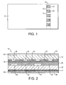
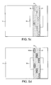
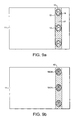
- Figure 1 shows a security device 10 according to the present invention incorporated into a security substrate 11, used to make secure documents, as a "windowed thread" with windows 12 in which areas of the device 10 are exposed and bridges 13 under which areas of the device 10 are embedded.
- the security device 10 can be incorporated into or arranged on the substrate 11 in any of the conventional formats known in the prior art, for example as patches, foils, stripes, strips or threads.
- the security device 10 can be arranged either wholly on the surface of the substrate 11, as in the case of a stripe or patch, or can be visible only partly on one surface of the substrate 11 in the form of a windowed security thread as shown in Figure 1 .
- EP-A-0860298 and WO-A-03095188 describe different approaches for the embedding of wider, partially exposed threads into a paper substrate.
- Wide threads typically having a width of 2-6mm, are particularly useful as the additional exposed thread surface area allows for better use of optically variable devices, such as those used in the present invention.
- the security device 10 of the present invention may be incorporated into a substrate 11 such that regions of the device 10 are visible on both sides of the substrate 11.
- Methods of incorporating a security device such that it is viewable from both sides of the substrate 11 are described in EP-A-1141480 and WO-A-3054297 .
- one side of the device is wholly exposed at one surface of the substrate 11 in which it is partially embedded, and partially exposed in windows at the other surface of the substrate.
- the security device 10 can be incorporated into the substrate 11 using a registration system such that the designs formed by the indicia are coincident with the windows or apertures in the substrate.
- a registration system such that the designs formed by the indicia are coincident with the windows or apertures in the substrate.
- One possible thread registration system described in GB-A-2395959 , monitors the location of a control feature on a security element as it is being unwound and fed into the papermaking machine and a control feature on the substrate as it is formed. The system uses these position indicators to control the tension of the security element and rate of its embedment, so that the control features of the security element and substrate are in register.
- the security device 10 is preferably prefabricated on a carrier strip and transferred to the substrate 11 in a subsequent working step.
- the security device 10 can be applied to the substrate 11 using an adhesive layer, which is applied either to the security device 10 or the surface of the security substrate 11 to which the device 10 is to be applied. After transfer the carrier strip is removed leaving the security device 10 exposed. Alternatively the carrier strip can be left in place to provide an outer protective layer.
- the security device 10 of the present invention can be used to authenticate documents made from a variety of substrates 11, but is particularly suitable for application to flexible substrates such as paper and polymer films.
- substrates 11 are particularly useful for making documents of value such as banknotes, travellers cheques, certificates of authenticity, stamps, bonds, tax discs, fiscal stamps, secure labels, passports or vouchers.
- the security substrate 11 generally undergoes further standard security printing processes to produce the secure document, including one or more of the following; wet or dry lithographic printing, intaglio printing, letterpress printing, flexographic printing, screen-printing, and/or gravure printing.
- wet or dry lithographic printing intaglio printing
- letterpress printing letterpress printing
- flexographic printing screen-printing
- gravure printing a printing technique that is used to produce the secure document.
- the design of the security device 10 is linked to the document it is protecting by content and registration to the designs and identifying information provided on the document.
- FIG. 2 shows a cross-sectional view of one embodiment of the security device 10 of the present invention suitable for application as a windowed security thread.
- the security device 10 is created by laminating together two layers which are opaque to visible light with clear regions which allow the transmission of visible light. These are provided by two partially metallised polymeric substrates 14, 15, for example Polyethylene Terephthalate (PET) or Bi-axially Oriented Polypropylene (BOPP) which form transparent carrier layers for opaque metal layers.
- PET Polyethylene Terephthalate
- BOPP Bi-axially Oriented Polypropylene
- the first partially metallised polymeric substrate 14 is produced such that no metal is present in controlled and clearly defined metal free (clear)regions 18.
- Such partially metallised film can be made in a number of ways. One way is to selectively demetallise regions using a resist and etch technique such as is described in US4652015 . Other techniques are known for achieving similar effects; for example it is possible to vacuum deposit aluminium through a mask or aluminium can be selectively removed from a composite strip of a plastic support and aluminium using an excimer laser.
- the metal free regions 18 take the form of indicia and are preferably in the form of images such as patterns, symbols and alphanumeric characters and combinations thereof.
- the second partially metallised polymeric substrate 15 also comprises metal free regions 19 in the metallised film.
- the two partially metallised polymeric substrates 14,15 are then laminated together with an adhesive layer 20 such that the red fluorescent layer 16 lies between the two substrates 14,15, as illustrated in Figure 2 .
- the lamination process is registered such that metal regions 22 in the second metallised substrate 15 are positioned to block out part of the indicia provided by the metal free regions 18 in the first metallised substrate 14.
- a masking coat may be applied to the surface of the security device 10 which is not exposed in the windows of the security document. In this case the masking coat would be applied to the fluorescent layer 17.
- Adhesive layers 23 may be applied to the outer surfaces of the device 10 to improve adherence to the security substrate 11.
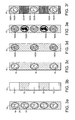
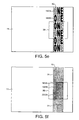
- Figures 3a to f illustrate one example of a security feature that could be generated from a security device 10 with the structure shown in Figure 2 and incorporated in a secure substrate 11, for example as a windowed security thread.
- Figure 3a is a plan view of the first partially metallised polymeric substrate 14 with the metal free regions 18 designed in the form of an image repeating along the length of the substrate 14, in this case a logo.
- Figure 3b is a plan view of the second partially metallised polymeric substrate 15 comprising alternating blocks of metal free regions 19 and metal regions 21.
- Both polymeric substrates 14, 15 are provided with a fluorescent layer 16,17 as indicated in Figure 2 .
- the two partially metallised polymeric substrates 14,15 are laminated together such that the metal regions 22 on the second partially metallised polymeric substrate 15 coincide with every other metal free region 18 on the first partially metallised polymeric substrate 14.
- the metal regions 22 in the second partially metallised polymeric substrate 15 block the light passing through every other image 18 such that only half of the indicia formed by the metal free regions 18 in the first partially metallised substrate 14 are visible in transmissive light, as illustrated in Figure 3c .
- the exact colour observed in transmitted UV light will vary depending on which surface the security device 10 is viewed from due to the fact that the combined colour depends on the order in which the light passes through them. For example, when viewed from the surface closest to the red fluorescent layer 16 the magenta colour 24 will have a noticeable red tint, and when viewed from the surface closest to the blue fluorescent layer 17 the observed magenta colour 24 will have a noticeable blue tint.
- the metal free regions 18 in the first partially metallised polymeric substrate 14 that are not coincident with the metal areas 22 in the second partially metallised polymeric substrate 15 will again appear in a magenta colour 24.
- the metal free regions 18 in the first partially metallised polymeric substrate 14 that are coincident with the metal areas 22 in the second partially metallised polymeric substrate 15 will appear red 25 as the metal areas 22 on the second partially metallised polymeric substrate 15 prevent the UV light from exciting the blue fluorescent layer 17.
- the authenticator observes a series of metal free regions 18 in alternate magenta 24 and red 25 colours ( Figure 3e ).
- the metal free regions 19 in the second partially metallised polymeric substrate 15 will appear magenta 24 as a result of a combination of the red light emitted by the fluorescent layer 16 and the blue light emitted by the fluorescent layer 17.
- the metal free regions 18 on the first partially metallised polymeric substrate 14 will appear in silhouette 29 within the magenta regions 24.
- the metal areas 22 on the second partially metallised polymeric substrate 15 will appear blue 28 as only the light from the blue fluorescent layer 17 is observed in these regions 18 due to the opacity of the metal areas 22 blocking the red fluorescent layer 16.
- the authenticator observes an alternating series of magenta and blue blocks 24,28 with a silhouette 29 of an image formed by the metal free regions 18 inside each magenta block 24 ( Figure 3f ).
- the security device 10 is incorporated into a security substrate 11 such that in localised regions, known as apertures, it is viewable from both sides of the substrate 11.
- a security substrate 11 such that in localised regions, known as apertures, it is viewable from both sides of the substrate 11.
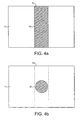
- FIG 4 illustrates an example of such a paper substrate 11 into which an elongate security device 10 is incorporated to create an aperture 30.
- both surfaces of the security device 10 are visible.
- the remainder of the device 10 is only visible from the front side of the substrate 11, as shown in Figure 4a , and not from the reverse side where the security device 10 is covered by paper fibres, as shown in Figure 4b .
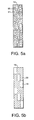
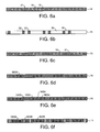
- Figures 5a to 5f illustrate another example of a security feature generated from a security device 10 with the structure shown in Figure 2 , incorporated into a paper substrate 11 according to the method described in W0-A-0039391 .
- Figure 5a is a plan view of the first partially metallised polymeric substrate 14 with the metal free regions 18 forming the word "ONE" oriented horizontally and repeating along the length of the security device 10 separated by metal areas 21.
- Figure 5b is a plan view of the second partially metallised polymeric substrate 15 comprising metal free regions 19 and metal areas 22. Both polymeric substrates 14,15 comprise a fluorescent layer 16,17 as indicated in Figure 2 .
- the two partially metallised polymeric substrates 14,15 are laminated together in register with the metal regions 22 on the second partially metallised polymeric substrate 15 coinciding with a number of the letters formed by the metal free regions 18 on the first partially metallised polymeric substrate 14.
- a series of words "ONE" are visible in a diagonal orientation.
- the security device 10 with the demetallised designs illustrated in Figures 5a and 5b is preferably incorporated into a substrate, such as paper, such that the first partially metallised polymeric substrate 14 is wholly exposed on the front surface of the paper substrate ( Figures 5c-5e ) and the second partially metallised polymeric substrate 15 is partially exposed in an aperture 30 on the back surface of the paper substrate 11 ( Figure 5f ).
- the diagonal repeating pattern "ONE" is observed in a combination of the visible colours emitted by the fluorescent layers 16,17( Figure 5d ).
- the diagonal word "ONE” will appear in a magenta colour 24 as a result of a combination of the red light emitted by the fluorescent layer 16 on the first partially metallised polymeric substrate 14 and the blue light emitted by the fluorescent layer 17 on the second partially metallised polymeric substrate 15.
- the diagonal word "ONE” will appear in a magenta colour 24.
- the metal free regions 18 forming the letters in the first partially metallised polymeric substrate 14 that are coincident with the metal areas 22 in the second partially metallised polymeric substrate 15 will appear red 25 due to the metal areas 22 on the second polymeric substrate 15 preventing the UV light from exciting the blue fluorescent layer 17.
- the authenticator observes the word "ONE” oriented horizontally and repeating along the length of the security device 10 with the colour of the letters arranged in magenta 24 and red 25 such that the diagonal word "ONE” is highlighted in magenta 24 ( Figure 5e ).
- the security device 10 On viewing the back surface of the substrate 11 the security device 10 is only exposed in the aperture 30 and embedded in the substrate 11 outside the aperture 30. In reflected ambient light the portion of the security device 10 exposed in the aperture 30 appears uniformly metallic with a silhouette 29 of the diagonal word "ONE" ( Figure 5f ).
- the device 10 In reflected UV light the device 10 will appear coloured in both the aperture 30 and embedded regions 31 although the colours will be significantly more intense on the part of the security device 10 exposed in the aperture 30.
- the metal free regions 19 in the second partially metallised polymeric substrate 15 will appear magenta 24 as a result of a combination of the red light emitted by the fluorescent layer 16 on the first partially metallised polymeric substrate 14 and the blue light emitted by the fluorescent layer 17 on the second partially metallised polymeric substrate 15.
- the diagonal word "ONE" will appear as a silhouette 29 within the blocks of magenta 24.
- the metal regions 22 in the second partially metallised polymeric substrate 15 will appear blue 28 as only the light from the blue fluorescent layer 17 is observed in these regions due to the opacity of the metal regions 22 blocking the red fluorescent layer 16.
- the authenticator observers an arrangement of magenta and blue blocks 24,28 with the magenta blocks 24 arranged in a diagonal pattern with the silhouette 29 of the word "ONE" running through the magenta blocks 27 ( Figure 5f ).
- Figures 6a to 6f illustrate a further example of a design for a security feature generated from a security device 10 of the present invention with the structure shown in Figure 2 .
- the security device 10 is in the form of a security thread.
- Figure 6a is a plan view of the first partially metallised polymeric substrate 14 with metal free regions 18 in the form of characters forming the word "FACET" repeating along the length of the security device 10 separated by metal areas 21.
- Figure 6b is a plan view of the second partially metallised polymeric substrate 15 comprising metal free regions 19 and metal areas 22.
- Each polymeric substrate 14,15 comprises a fluorescent layer 16,17 as indicated in Figure 2 .
- the two polymeric substrates 14,15 are laminated together in register, with the metal areas 22 on the second partially metallised polymeric substrate 15 coinciding with the demetallised "F” and the "T” characters on the first partially metallised polymeric substrate 14 such that when the security device 10 is viewed in transmission ( Figure 6c ) in ambient lighting the word "ACE" is observed repeating along the device 10.
- the word "ACE” On viewing the security device 10 under transmitted UV illumination the word "ACE” is observed in a combination of the visible colours emitted by the fluorescent layers.
- the word “ACE” will appear in a magenta colour 24 ( Figure 6d ) as a result of a combination of the red light emitted by the fluorescent layer 16 on the first partially metallised polymeric substrate 14 and the blue light emitted by the fluorescent layer 17 on the second partially metallised polymeric substrate 15.
- the word "ACE” will again appear in a magenta colour 24.
- the letters formed by the metal free regions 18 in the first partially metallised polymeric substrate 14 that are coincident with the metal areas 22 on the second partially metallised polymeric substrate 15 will appear red 25 due to the areas 22 on the second partially metallised polymeric substrate 15 preventing the UV light from exciting the blue fluorescent layer 17.
- the authenticator observes the word “FACET” repeating along the length of the security device 10 with the letters “ACE” being in magenta 24 and the letters "F” and "T” being in red 25( Figure 6e ).
- the metal free regions 19 in the second partially metallised polymeric substrate 15 will appear magenta 24.
- the word "ACE” will appear as a silhouette 29 within the magenta regions 24.
- the metal areas 22 in the second partially metallised polymeric substrate 15 will appear blue 28 as only the light from the blue fluorescent layer 17 is observed in these areas 22 due to the opacity of the metal areas 21 blocking out the red fluorescent layer 16.
- the authenticator observes a series of magenta blocks 24, inside which is a silhouette of the word "ACE", separated by blue blocks 28( Figure 6f )
- the first or the second partially metallised polymeric substrate 14,15 is a sacrificial carrier film and is discarded after the lamination process.
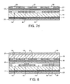
- the use of a sacrificial carrier film is illustrated in Figures 7a to 7d .
- Figure 7a illustrates the first metallised polymeric film 14, which is as described in relation to Figure 2 except in that it now comprises a release layer 32 between the first polymeric substrate 14 and the metal areas 21.
- Figure 7b illustrates the second metallised polymeric substrate 15 which comprises the layers described in relation to Figure 2 .
- the two partially metallised polymeric substrates 14,15 are laminated together with an adhesive layer 20 using a registered process such that the metal areas 22 on the second partially metallised substrate 15 are positioned to block out some of the indicia formed by the metal free regions 21 on the first partially metallised substrate 14, see figure 7c
- the first polymeric substrate 14 is then stripped away at the release layer 32 to leave the final structure of the security device 10 as shown in Figure 7d .
- the advantage of using a sacrificial carrier layer for either the first or second polymeric substrates 14,15 is that it significantly reduces the thickness of the final security device 10. This is particularly important for security devices 10 used in security documents which have to be sorted and distributed using automated cash handling equipment where any localised increase in thickness can result in handling problems.
- the second partially metallised substrate 15 in Figure 2 is replaced with a coloured opaque layer which has gaps or clear regions.
- This embodiment will have the same appearance as the structure of Figure 2 when viewed in transmitted ambient light and reflected and transmitted UV light.
- an additional visual effect is observed in that the metal free regions 18 in the first partially metallised polymeric substrate 14 not coincident with the clear regions (which correspond to the metal free regions 19) in the coloured opaque layer will be readily apparent due to the contrast between the coloured opaque layer and the metallic background.
- This provides the additional benefit in ambient light of revealing one image in reflected light, when viewed from the surface of the first partially metallised polymeric substrate 14, and a different image in transmitted light.
- the security device 10 When the security device 10 is incorporated into a document such that its bottom surface 26 is exposed either wholly or in localised regions/windows 12 on the front or back surface of the document then the second partially metallised polymeric substrate 15 or the replacement coloured opaque layer will be visible.
- a coloured opaque layer such as a black pigmented ink
- the additional security benefit it provides in ambient reflected light is compromised by the poor aesthetic appearance of the exposed coloured opaque layer on the front or back surface of the document.
- Figure 8 illustrates an alternative structure of the security device 10 of the present invention which provides the additional benefit, in ambient light, of revealing one image in reflected light and a different image in transmitted light whilst still providing an aesthetically pleasing metallic appearance when viewed from both sides of the security device 10.
- the device 10 has a similar structure to that shown in Figure 2 with an additional opaque coloured material 34 applied between the red fluorescent layer 16 and the second metal areas 22.
- the opaque coloured material 34 is applied in register with the first metal areas 21 such that it is visible through the metal free regions 18 in the first partially metallised polymeric substrate 14 that are coincident with the metal areas 22 in the second partially metallised polymeric substrate 15.
- the laminated structure of the security device 10 of Figure 8 will show the same behaviour as the laminated structure of the security device 10 of Figure 2 when viewed in ambient transmitted light and transmitted and reflected UV light.
- the security device 10 of Figure 8 will show an additional effect when viewed from its top surface 27 in ambient reflected light in which the metal free regions 18 coincident with the opaque coloured material 34 will be readily apparent due to the contrast between the opaque coloured material 34 and the metallic background.
- FIGs 9a to 9e illustrate yet another example of a security feature, generated from security device 10 of the present invention with the structure shown in Figure 8 .
- the two partially metallised polymeric substrates 14,15 have the same demetallised designs as shown in Figures 3a and 3b and the security device 10 is preferably incorporated into a paper substrate 11 as a windowed security device 10 such that the second partially metallised polymeric substrate 15 ( Figure 3b ) is exposed in the windows 12.
- the metal regions 22 on the second polymeric substrate 15 block the light passing through every other image formed by the metal free regions 18.
- the metal free regions 19 in the second partially metallised polymeric substrate 15 will appear magenta 24.
- the image formed by the metal free regions 18 on the first partially metallised polymeric substrate 14 will appear as a silhouette 29 within the magenta regions 24.
- the metal areas 22 in the second partially metallised polymeric substrate 15 will appear blue 28 as only the light from the blue fluorescent layer 17 is observed in these areas 22 due to the opacity of the metal areas 22 blocking out the red fluorescent layer 16.
- the authenticator observers an alternating series of magenta and blue blocks 24,28 with a silhouette of an image inside each magenta block 24. In reflected UV light the images will be visible in both the windows 12 and embedded regions 13 although the colours will be significantly more intense in the windows 12.
- the coloured opaque layer 34 may be applied onto localised regions of the second partially metallised substrate 15, as shown in Figure 8 , using any common printing technique.
- the localised printed regions are preferably the same width or wider than the corresponding indicia formed by the metal free regions 18 in the first partially metallised polymeric substrate 14 .
- the resist forms the opaque coloured layer 34.
- the second metallised polymeric film 15 is printed with a resist containing a coloured dye or pigment.
- Suitable resists include the dye BASF Neozapon X51 or the pigment (well dispersed) "Carbon Black 7" mixed into a material with both good adhesion to metal and caustic resistance.
- the dye loading can be up to 50% (by weight) of the final coat of resist depending on coat thickness and desired blackness.
- An example of a class of suitable resist materials is vinyl chlorides/vinyl acetate copolymers such as Union Carbide Ucar resins, Sun VHL 31534, or Wacker Vinnol E 15/45m.
- the printed second metallised film 15 is then partially demetallised, according to a known demetallisation process using a caustic wash which removes the metal in the regions not printed with the resist.
- the remaining metal areas 22 are still coated with resist, which provides a dark opaque layer 34 which is visible when the security device 10 of Figure 10 is viewed from its top surface 27 in reflection.
- the dye or pigment in the coloured opaque layer 34 may be a conducting material, such as carbon black, to produce a machine-readable or conducting layer.
- a conducting material such as carbon black
- it may be a magnetic material, such as magnetite, to produce a machine readable magnetic layer.
- the inventive structure of the security device 10 of the present invention enables designs to be created that are striking and memorable to the general public, but are very complex which makes is very difficult for a potential counterfeiter to try to reproduce.
- the highly contrasting appearances when viewed in different light sources and from different sides enables the security device to be readily recognisable to the user.
- the additional requirement to accurately register the metal free regions 18, 19 on the front and back of the device 10 is very hard to counterfeit effectively.
- the laminated structure of the security device 10 illustrated in Figure 2 has an additional advantage in that the two sets of metal areas 21,22 are in the middle of the laminated structure and are not exposed. This overcomes a known disadvantage of demetallised security threads which is their susceptibility to corrosive or abrasive effects during paper manufacturing and in circulating banknotes. In the structure illustrated in Figure 2 the two sets of metal areas 21,22 are protected from any corrosion or abrasion by the polymeric substrates 14,15.
- the metal areas 21,22 could be on the opposite sides of their respective polymeric substrates 14,15.
- the only requirement is that there is a fluorescent layer 16 in between the two sets of metal areas 21,22 and a fluorescent layer 17 of a different colour external to the two sets of metal areas 21,22.
- FIG 11 shows a further alternative structure for a security device 10 of the present invention suitable for incorporation into a security document.
- the security device 10 comprises a single layer 35 of a polymeric substrate, for example Polyethylene Terephthalate (PET) or Bi-axially Oriented Polypropylene (BOPP)which is metallised on both surfaces.
- a fluorescent material 16 is present in the polymeric substrate 35 or on the top surface of the substrate 35.
- the fluorescent material 16 is colourless in normal daylight but emits a specific visible colour when excited by UV radiation.
- the metallised polymeric substrate 35 is partially demetallised such that the top surface comprises first metal free regions 18 and first metal areas 21 which are used to create indicia in the form of identifying images and the bottom surface comprises second metal free regions 19 and second metal areas 22.
- the first metal free regions 18, 19 are arranged such that the second metal areas 22 layer are positioned to block out part of the information provided by the first metal free regions 18.
- Adhesive layers 20 can be applied to the outer surfaces of the device 10 to improve adherence to the secure document.
- the invention is not limited to any particular colour combination of the fluorescent layers 16,17, and example colour combinations of the two fluorescent layers 16,17 are given in the table below.
- Fluorescent layer 16 Fluorescent layer 17 Combined colour when viewed in transmitted light. Red Yellow Orange Yellow Blue Green Red Blue Purple Green Blue Cyan Red Blue Magenta
- the present invention is also not limited to UV activated fluorescent materials. Any fluorescent materials can be used that respond visibly to invisible radiation such as phosphorescent materials, IR activated materials, photochromic materials and thermochromic materials.
- inks in particular metallic or metal effect inks and more preferably high reflectivity metallic or metal effect inks, may be deposited on the polymeric substrates 14,15 by a printing technique to form opaque layers with negative indicia.
- metallic or metal effect inks in particular metallic or metal effect inks and more preferably high reflectivity metallic or metal effect inks
- other optical effect inks can be used e.g. OVI® optically variable inks.
- opaque-coloured printing inks can be used.
- liquid crystal polymeric films or inks can be used.
- Figure 12 illustrates an example where the second opaque layer is obtained by combining a layer 36 of a liquid crystal material with a darkly coloured background absorbing layer 37 to enhance the colourshifting effect of the liquid crystal material.
- the liquid crystal layer 36 exhibits a red to green colourshift when viewed in reflection over the dark absorbing layer 37.
- the absorbing layer 36 comprises an opaque design printed on the second polymeric substrate 15 using a dark ink or dye.
- a liquid crystal film is then applied over the design using a coating or laminating process.
- the opaque designs can be overprinted using a liquid crystal ink e.g. Oasis® ink from SICPA.
- the security device 10 of Figure 12 will show the same behaviour as the security device 10 of Figure 2 when viewing in ambient transmitted light and transmitted and reflected UV light. Furthermore the security device 10 of Figure 12 will show an additional effect when viewed from its top surface 27 in ambient reflected light in which the first metal free regions 18 coincident with the liquid crystal layer 36 superimposed on the dark absorbing layer 37 will be readily apparent due to the contrast between the optically variable liquid crystal material, exhibiting a red to green colourshift, and the metallic background.
- the security device 10 of Figure 12 is incorporated into a substrate 11 such that the bottom surface 26 of the security device 10 is exposed either wholly or in localised regions/windows 12 on the front or back surface of the substrate 11, then the dark absorbing layer 37 may be visible. If this is not desirable then a masking coat may be used to obscure the dark absorbing layer 37 and a suitable material for such a masking coat would be Coates 3188XSN or Coates Heliovyl White S90 353. A typical coat weight is suggested to be in the region of 2GSM. Alternatively the dark absorbing layer 37 may be masked by a second metallised layer using similar structures to those described in Figures 8 and 10 .
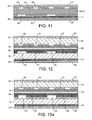
- Figure 13a shows an embodiment of the security device 10 of the present invention having a similar structure to that shown in Figure 10 , but in which the second metallised polymeric layer 15 is selectively demetallised using a resist and etch technique and in which the resist contains a black coloured dye or pigment.
- a layer 36 of a liquid crystal film is applied over the dark absorbing layer 37 provided by the black resist, such that when the security device 10 is viewed from its top surface 27 in ambient reflected light the first metal free regions 18 coincident with the liquid crystal layer 36 superimposed on the layer 37 of black resist will exhibit a colourshift.
- Figure 13b shows a further embodiment of the security device 10 of the present invention comprising a liquid crystal layer 36.
- the structure is similar to that shown in Figure 2 , but in which the first metallised polymeric layer 14 is selectively demetallised using a resist and etch technique and in which the resist contains a black coloured dye or pigment.
- a layer 36 of a liquid crystal film is applied over the dark absorbing layer 37 provided by the black resist, such that when the security device 10 is viewed from its top surface 27 in ambient reflected light an angular dependent colourshift will be observed where the liquid crystal layer 36 is superimposed on the layer 37 of black resist.
- the security device 10 may also be used to provide machine-readable information.
- the opaque layers formed by the first and second metals areas 21,22 may be applied using a magnetic or conductive ink.
- the opaque layers could be applied using a vapour deposited magnetic material for example Fe, Ni or Co.
- Figure 14 illustrates an approach to forming a machine-readable construction of a security device 10 of the present invention for application as a windowed security device 10.
- the device 10 has a similar structure to that shown in Figure 2 with a magnetic material applied in localised regions between the two partially metallised polymeric layers 14,15.
- the magnetic material can be applied in any design but common examples include the use of magnetic tramlines or the use of magnetic blocks 39 to form a coded structure.
- Suitable magnetic materials include iron oxide pigments (Fe 2 O 3 or Fe 3 O 4 ), barium or strontium ferrites, iron, nickel, cobalt and alloys of these.
- alloys includes materials such as Nickel:Cobalt, Iron:Aluminium:Nickel:Cobalt and the like.
- Flake Nickel materials can be used; in addition Iron flake materials are suitable. Typical nickel flakes have lateral dimensions in the range 5-50 microns and a thickness less than 2 microns. Typical iron flakes have lateral dimensions in the range 10-30 microns and a thickness less than 2 microns.
- a transparent magnetic composite material can be incorporated at any position within the structure of the security device 10.
- Suitable transparent magnetic composite materials containing a distribution of particles of a magnetic material of a size and distributed in a concentration at which the magnetic composite material remains transparent are described in WO-A-03091953 and WO-A-03091952 .
- the security device 10 of the present invention may also include other anti-counterfeiting materials, such as thermochromic materials, liquid crystal coatings or films, colourshifting inks, colourshifting interference films and holographic generating structures.
- other anti-counterfeiting materials such as thermochromic materials, liquid crystal coatings or films, colourshifting inks, colourshifting interference films and holographic generating structures.
- Figure 15 shows an embodiment of the current invention comprising a holographic generating structure.
- the structure is similar to that shown in Figure 2 but with an additional layer 40 of lacquer applied to the first polymeric substrate 14 before it is metallised.
- the security device 10 of Figure 15 will show the same behaviour as the security device 10 of Figure 2 when viewing in ambient transmitted light and transmitted and reflected UV light. Furthermore the security device 10 of Figure 15 will display a holographic image when viewed from its top surface 27 in ambient reflected light. On viewing the security device 10 of Figure 15 from its bottom surface in ambient reflected light the holographic image is visible in the metal free regions 18 in the first partially metallised polymeric substrate 14 that are not coincident with the metal areas 22 in the second partially metallised polymeric substrate.
- At least one of the opaque layers is provided by a layer which is transparent to visible light but opaque to light in the non-visible ultra-violet wavelength range of the electromagnetic spectrum.
- the security device will have the structure shown in Figure 2 except that the metal regions 22 are now replaced with a UV absorbing coating which is substantially transparent to visible light but opaque to non-visible UV radiation.
- Suitable UV absorbing coatings include a UV barrier coating supplied by Sun Chemical with the product code NMHR-70-20669.
- a suitable UV absorbing compound which could be applied to conventional coatings is a hydroxyphenyl triazine class of UV absorber sold under the name Tinuvin® 400 by Ciba®.
- Figures 16a to 16f illustrate one example of a security feature that could be generated from a security device with this construction.
- Figure 16a is a plan view of a polymeric substrate 14 which has been metallised to provide opaque metal regions 21 and comprises metal free regions 18 designed in the form of an image repeating along the length of the substrate 14, in this case a logo.
- Figure 16b is a plan view of a second polymeric substrate 15 comprising blocks 41 of a UV absorbing coating which is substantially transparent to visible light but is opaque to UV light. Gaps 19 are provided between the blocks 41 which allow the transmission of UV and visible light.
- Both of the polymeric substrates 14, 15 are provided with a fluorescent layer 16, 17 as indicated in Figure 2 .
- the two polymeric substrates 14, 15 are laminated together such that the UV opaque blocks 41 on the second polymeric substrate 15 coincide with every other metal free region 18 on the first partially metallised polymeric substrate 14.
- a combination of the visible colours emitted by the fluorescent layers 16, 17 are observed in the metal free regions 18 in the first metallised polymeric substrate 14 that are not coincident with the UV absorbing blocks 41 on the second polymeric substrate 15( Figure 3d ).
- the images will appear in a magenta colour 24 as a result of a combination of the red light emitted by the fluorescent layer 16 on the first partially metallised polymeric substrate 14 and the blue light emitted by the fluorescent layer 17 on the second polymeric substrate 15.
- the exact colour observed in transmitted UV light will vary depending on which surface 26,27 the security device 10 is viewed from due to the fact that the combined colour depends on the order in which the light passes through them. For example, when viewed from the surface closest to the red fluorescent layer 16 the magenta colour 24 will have a noticeable red tint.When viewed from the surface closest to the blue fluorescent layer 17 the observed magenta colour 24 will have a noticeable blue tint.
- the metal free regions 18 in the first partially metallised polymeric substrate 14 that are not coincident with the UV absorbing blocks 41 on the second polymeric substrate 15 will again appear in a magenta colour 24.
- the metal free regions 18 in the first partially metallised polymeric substrate 14 that are coincident with the UV absorbing blocks 41 in the second polymeric substrate 15 will appear red as the UV absorbing blocks 41 on the second polymeric substrate 15 prevent the UV light from exciting the blue fluorescent layer 17. In this manner the authenticator observes a series of metal free regions in alternate magenta and red colours 24,25( Figure 16e ).
- the gaps 19 between the UV absorbing blocks 41 on the second polymeric substrate 15 will appear magenta 24 as a result of a combination of the red light emitted by the fluorescent layer 16 and the blue light emitted by the fluorescent layer 17.
- the metal free regions 18 on the first partially metallised polymeric substrate 14 will appear in silhouette 29 within the magenta regions 24.
- the UV absorbing blocks 41 on the second polymeric substrate 15 will appear blue as only the light from the blue fluorescent layer 17 is observed in these regions due to the UV absorbing blocks 41 preventing UV light from exciting the red fluorescent layer 16.
- UV opaque layers are applicable to any of the previously described embodiments of the present invention.
- Figure 11 which comprises a single layer of PET with a patterned opaque metallised layer on either side
- one of the metallised layers could be replaced with a UV absorbing layer which is substantially transparent to visible light.
Abstract
Description
- The invention relates to a security device for security substrates, such as paper, used for making security documents, such as bank notes, having anti-counterfeitable features.
- It is generally known to include elongate elements in paper or other substrates, usually as a security feature. Such elements can be threads, strips or ribbons of, for example, plastic film, metal foil, metallised plastic, metal wire. These elongate elements are included in the thickness of the substrate to render imitation of documents produced therefrom more difficult. These elements help in the verification of the documents as they render the view of the documents in reflected light different from that in transmitted light. To increase the security provided by the inclusion of such an elongate element, it is also known to endow the element itself with one or more verifiable properties over and above its presence or absence. Such additional properties include magnetic properties, electrical conductivities, the ability to absorb x-rays, fluorescence, phosphorescence, optically variable effects and thermochromic behaviour.
- As a further security feature, it has been found to be particularly advantageous to provide windows in one side of the surface of the substrate, which expose such elongate elements at spaced locations. Examples of methods of manufacturing paper incorporating security elements with or without windows are described below. It should be noted that references to "windowed thread paper" include windowed paper incorporating any elongate security element.
-
EP-A-0059056 describes a method of manufacture of windowed thread paper on a cylinder mould paper-making machine. The technique involves embossing the cylinder mould cover to form raised regions and bringing an impermeable elongate security element into contact with the raised regions of the mould cover, prior to the contact entry point into a vat of aqueous paper stock. Where the impermeable security element makes intimate contact with the raised regions of the embossing, no fibre deposition can occur and windows are formed in the surface of the paper. After the paper is fully formed and couched from the cylinder mould cover, water is extracted from the wet fibre mat and the paper is passed through a drying process. In the finished paper the regions of the security element which are exposed in the windows are visible in reflected light on one side of the paper. This feature is commonly used for banknotes. - The widespread use of security documents having security elements exposed in windows along the length of the element has resulted in enhanced security. A security document of this type provides this enhancement as, when viewed in transmitted light, the security element provides a different view from that which is seen under reflected light, where parts of the security element are readily visible in the windows. However, there is a continual need for further enhanced security features to render the task of a would-be counterfeiter more difficult.
- A significant development is described in
EP-A-0319157 which describes the incorporation in security paper of a security thread which has a recognisable pattern, design or indicia provided by partially demetallising a metallised carrier substrate. The metal free portions are preferably letters which are clearly visible, when the security paper is viewed in transmitted light, as strong highlights against a much darker metal background. The indicia can advantageously be legends or numerals relating to the security document itself, e.g. the denomination of a banknote. - A further development is described in
GB-A-2323814 - In addition to demetallisation it is also well known to provide security threads with a wide range of additional security features. One class of additional security features are those commonly referred to as teller assist features. These are features that require a simple hand held device to view them. A common teller assist security feature is one based on luminescent materials. Luminescent materials are known to those skilled in the art to include materials having fluorescent or phosphorescent properties. It is also well known to use other materials that respond visibly to invisible radiation, such as photochromic materials and thermochromic materials. The use of luminescent security features on threads has been described in
EP-A-303725 EP-A-319157 WO-A-2006051231 , as well as in numerous other patent publications. - In one embodiment described in
EP-A-319157 EP-A-319157 - A similar type of security thread to the one described in
EP-A-319157 WO-A-2006051231 . In this document a security thread comprises an opaque layer with gaps to form indicia on a transparent polymeric carrier film. Different fluorescent materials are applied to either side of the security thread such that in reflection the two surfaces emit a different colour when exposed to UV light. When viewed in transmission in UV light, a third and potentially fourth colour, depending on from which surface the security thread is viewed, is observed in the gaps in the opaque layer resulting from the combination of the two surface colours. - The examples in the prior art describe a security element comprising an image created by gaps in an opaque layer that is visible in transmission or on exposure to UV light. Furthermore the security feature comprises zones fluorescing in two or more colours. A problem with the structure of the security devices described in the prior art is that, in order to achieve multiple coloured fluorescent zones, the fluorescent material is applied to the opaque materials. In most cases the opaque material is metallic and has a characteristic sheen which, when exposed in a secure document, attracts the attention of the authenticator. If a fluorescent material is applied to the metallic layer there will be an undesirable reduction in the metallic sheen. This is of particular concern if the fluorescent material is a pigmented lacquer. The superior lightfastness of pigmented fluorescent lacquers compared to organic dyes means that they are the preferred materials in security devices employed in documents, such as banknotes, where the feature must withstand a long lifetime in circulation.
- It is an object of the present invention to provide a security device which comprises a multilayer structure that exhibits the aforementioned fluorescent security features of the prior art without the need for applying the fluorescent material to a glossy metallic layer. It is a further object to provide a multilayer structure which enables a different identifying image to be observed depending on whether the appropriate illumination source, for example a UV light, is in front or behind the document.
- The invention therefore provides a security device comprising a first opaque layer and a second opaque layer, said opaque layers each having a plurality of clear regions, a first fluorescent layer positioned between the first and second opaque layers, a second fluorescent layer, separated from the first fluorescent layer by one of the opaque layers, said first and second fluorescent layers exhibiting different visible colours under ultraviolet light wherein the clear regions in the first opaque layer form indicia and the clear regions in the second opaque layer overlap with only some of the clear regions in the first opaque layer.
- Preferred embodiments of the present invention will now be described, by way of example only, with reference to the accompanying drawings in which:-
-
Figure 1 is a plan view of a security substrate incorporating a security device according to the invention; -
Figure 2 is a cross-sectional end elevation of the security device ofFigure 1 ; -
Figures 3a and 3b are plan views of two partially metallised polymeric substrates which are laminated together to form an alternative security device, plan views of which are shown inFigures 3c to 3f illustrating different viewing conditions; -
Figures 4a and 4b are plan views of the front and rear of a security substrate incorporating a further alternative security device; -
Figures 5a and 5b are plan views of two partially metallised polymeric substrates which are laminated together to form a further alternative security device, plan views of which are shown inFigures 5c to 5f illustrating different viewing conditions; -
Figures 6a and 6b are plan views of two partially metallised polymeric substrates which are laminated together to form a yet further alternative security device, plan views of which are shown inFigures 6c to 6f illustrating different viewing conditions; -
Figures 7a and 7b are cross-sectional end elevations of two partially metallised polymeric substrates which are laminated together to form a still further alternative security device, cross-sectional end elevations of which are shown inFigures 7c and7d ; -
Figure 8 is a cross-sectional end elevation of another embodiment of a security device of the present invention; -
Figures 9a to 9e are plan views of the front and rear of a substrate in which the security devices ofFigure 8 is incorporated illustrating different viewing conditions; -
Figures 10 to 15 are cross-sectional end elevations of still further embodiments of a security device of the present invention; and -
Figures 16a and 16b are plan views of two polymeric substrates which are laminated together to form a further alternative security device, plan views of which are shown inFigures 16c to 16f illustrating different viewing conditions. - A
security device 10 according to the present invention has two opaque layers which are preferably supported by one or more substantially transparent carrier layers. The opaque layers may be opaque to visible light and/or opaque to light (radiation) in the non-visible spectrum. Each opaque layer is provided with gaps which partially overlap with the gaps in the other layer. The gaps are transparent to, and therefore allows transmission of, the relevant form of light. Two fluorescent layers are located so as to provide a range of different visual effects when thedevice 10 is viewed under different viewing conditions. -
Figure 1 shows asecurity device 10 according to the present invention incorporated into asecurity substrate 11, used to make secure documents, as a "windowed thread" withwindows 12 in which areas of thedevice 10 are exposed and bridges 13 under which areas of thedevice 10 are embedded. Thesecurity device 10 can be incorporated into or arranged on thesubstrate 11 in any of the conventional formats known in the prior art, for example as patches, foils, stripes, strips or threads. Thesecurity device 10 can be arranged either wholly on the surface of thesubstrate 11, as in the case of a stripe or patch, or can be visible only partly on one surface of thesubstrate 11 in the form of a windowed security thread as shown inFigure 1 .EP-A-0860298 andWO-A-03095188 - The
security device 10 of the present invention may be incorporated into asubstrate 11 such that regions of thedevice 10 are visible on both sides of thesubstrate 11. Methods of incorporating a security device such that it is viewable from both sides of thesubstrate 11 are described inEP-A-1141480 andWO-A-3054297 EP-A-1141480 one side of the device is wholly exposed at one surface of thesubstrate 11 in which it is partially embedded, and partially exposed in windows at the other surface of the substrate. - The
security device 10 can be incorporated into thesubstrate 11 using a registration system such that the designs formed by the indicia are coincident with the windows or apertures in the substrate. One possible thread registration system, described inGB-A-2395959 - In the case of a stripe or patch, the
security device 10 is preferably prefabricated on a carrier strip and transferred to thesubstrate 11 in a subsequent working step. Thesecurity device 10 can be applied to thesubstrate 11 using an adhesive layer, which is applied either to thesecurity device 10 or the surface of thesecurity substrate 11 to which thedevice 10 is to be applied. After transfer the carrier strip is removed leaving thesecurity device 10 exposed. Alternatively the carrier strip can be left in place to provide an outer protective layer. - The
security device 10 of the present invention can be used to authenticate documents made from a variety ofsubstrates 11, but is particularly suitable for application to flexible substrates such as paper and polymer films.Such substrates 11 are particularly useful for making documents of value such as banknotes, travellers cheques, certificates of authenticity, stamps, bonds, tax discs, fiscal stamps, secure labels, passports or vouchers. - Following the application of the
security device 10, thesecurity substrate 11 generally undergoes further standard security printing processes to produce the secure document, including one or more of the following; wet or dry lithographic printing, intaglio printing, letterpress printing, flexographic printing, screen-printing, and/or gravure printing. In a preferred embodiment of the invention, and to increase the effectiveness of thesecurity device 10 against counterfeiting, the design of thesecurity device 10 is linked to the document it is protecting by content and registration to the designs and identifying information provided on the document. -
Figure 2 shows a cross-sectional view of one embodiment of thesecurity device 10 of the present invention suitable for application as a windowed security thread. Thesecurity device 10 is created by laminating together two layers which are opaque to visible light with clear regions which allow the transmission of visible light. These are provided by two partially metallisedpolymeric substrates - The first partially metallised
polymeric substrate 14 is produced such that no metal is present in controlled and clearly defined metal free (clear)regions 18. Such partially metallised film can be made in a number of ways. One way is to selectively demetallise regions using a resist and etch technique such as is described inUS4652015 . Other techniques are known for achieving similar effects; for example it is possible to vacuum deposit aluminium through a mask or aluminium can be selectively removed from a composite strip of a plastic support and aluminium using an excimer laser. The metalfree regions 18 take the form of indicia and are preferably in the form of images such as patterns, symbols and alphanumeric characters and combinations thereof. Possible characters include those from non-Roman scripts of which examples include but are not limited to, Chinese, Japanese, Sanskrit and Arabic. A layer of a firstfluorescent material 16, which in this case is colourless in normal daylight but emits red light when excited by UV radiation, is then applied uniformly over the partially metallised side of thefirst substrate 14 including the metalfree regions 18. - The second partially metallised
polymeric substrate 15 also comprises metalfree regions 19 in the metallised film. A layer of a secondfluorescent material 17, which in this case is colourless in normal daylight but emits blue light when excited by UV radiation, is applied uniformly to the non-metallised side of the secondpolymeric substrate 15. The two partially metallisedpolymeric substrates adhesive layer 20 such that thered fluorescent layer 16 lies between the twosubstrates Figure 2 . The lamination process is registered such thatmetal regions 22 in the secondmetallised substrate 15 are positioned to block out part of the indicia provided by the metalfree regions 18 in the firstmetallised substrate 14. A masking coat may be applied to the surface of thesecurity device 10 which is not exposed in the windows of the security document. In this case the masking coat would be applied to thefluorescent layer 17. Adhesive layers 23 may be applied to the outer surfaces of thedevice 10 to improve adherence to thesecurity substrate 11. - The registration between the first and second partially metallised
substrates Figures 3-6 .Figures 3a to f illustrate one example of a security feature that could be generated from asecurity device 10 with the structure shown inFigure 2 and incorporated in asecure substrate 11, for example as a windowed security thread.Figure 3a is a plan view of the first partially metallisedpolymeric substrate 14 with the metalfree regions 18 designed in the form of an image repeating along the length of thesubstrate 14, in this case a logo.Figure 3b is a plan view of the second partially metallisedpolymeric substrate 15 comprising alternating blocks of metalfree regions 19 andmetal regions 21. Bothpolymeric substrates fluorescent layer Figure 2 . The two partially metallisedpolymeric substrates metal regions 22 on the second partially metallisedpolymeric substrate 15 coincide with every other metalfree region 18 on the first partially metallisedpolymeric substrate 14. - On viewing the
security device 10 formed from the laminated structure in transmissive visible light in ambient conditions, themetal regions 22 in the second partially metallisedpolymeric substrate 15 block the light passing through everyother image 18 such that only half of the indicia formed by the metalfree regions 18 in the first partially metallisedsubstrate 14 are visible in transmissive light, as illustrated inFigure 3c . - On viewing the
security device 10 formed from thelaminated structure 10 under transmitted UV illumination, a combination of the visible colours emitted by the fluorescent layers 16,17 are observed in the metalfree regions 18 in the first partially metallisedpolymeric substrate 14 that are not coincident with themetal areas 22 in the second partially metallised polymeric substrate 15 (Figure 3d ). For the structure described inFigure 2 the images will appear in amagenta colour 24 as a result of a combination of the red light emitted by thefluorescent layer 16 on the first partially metallisedpolymeric substrate 14 and the blue light emitted by thefluorescent layer 17 on the second partially metallisedpolymeric substrate 15. The exact colour observed in transmitted UV light will vary depending on which surface thesecurity device 10 is viewed from due to the fact that the combined colour depends on the order in which the light passes through them. For example, when viewed from the surface closest to thered fluorescent layer 16 themagenta colour 24 will have a noticeable red tint, and when viewed from the surface closest to theblue fluorescent layer 17 the observedmagenta colour 24 will have a noticeable blue tint. - On viewing the
top surface 27 of thesecurity device 10 under reflected UV light, the metalfree regions 18 in the first partially metallisedpolymeric substrate 14 that are not coincident with themetal areas 22 in the second partially metallisedpolymeric substrate 15 will again appear in amagenta colour 24. However, the metalfree regions 18 in the first partially metallisedpolymeric substrate 14 that are coincident with themetal areas 22 in the second partially metallisedpolymeric substrate 15 will appear red 25 as themetal areas 22 on the second partially metallisedpolymeric substrate 15 prevent the UV light from exciting theblue fluorescent layer 17. In this manner the authenticator observes a series of metalfree regions 18 inalternate magenta 24 and red 25 colours (Figure 3e ). - On viewing the
security device 10 under reflected UV light from thebottom surface 26, the metalfree regions 19 in the second partially metallisedpolymeric substrate 15 will appear magenta 24 as a result of a combination of the red light emitted by thefluorescent layer 16 and the blue light emitted by thefluorescent layer 17. As thedevice 10 is being viewed in reflected light, the metalfree regions 18 on the first partially metallisedpolymeric substrate 14 will appear insilhouette 29 within themagenta regions 24. Themetal areas 22 on the second partially metallisedpolymeric substrate 15 will appear blue 28 as only the light from theblue fluorescent layer 17 is observed in theseregions 18 due to the opacity of themetal areas 22 blocking thered fluorescent layer 16. The authenticator observes an alternating series of magenta andblue blocks silhouette 29 of an image formed by the metalfree regions 18 inside each magenta block 24 (Figure 3f ). - When the
security device 10 illustrated inFigures 2 and3 is incorporated into asecurity substrate 11 as a windowed security thread such that the top surface of the first partially metallisedpolymeric substrate 14 is exposed in thewindows 12, the authenticity of a document made from thesubstrate 11 can be checked in a number of ways:- - 1. By viewing the document in transmission in ambient lighting conditions to check the clear images formed by the metal
free regions 18; - 2. By viewing the document in transmitted UV light to check the
single fluorescent colour 24 of the images formed by the metalfree regions 18; - 3. By viewing the front of the document in reflected UV light to check for multicoloured 24,25 fluorescent images formed by the metal
free regions 18 appearing in the windows; - 4. By viewing the back of the document in reflected UV light to check for a different pattern of multicoloured 24,28 fluorescent images to that observed on the front of the document.
- In a further example the
security device 10 is incorporated into asecurity substrate 11 such that in localised regions, known as apertures, it is viewable from both sides of thesubstrate 11. One method for creating such apertures in a paper substrate is described inWO-A-0039391 Figure 4 illustrates an example of such apaper substrate 11 into which anelongate security device 10 is incorporated to create anaperture 30. In theaperture 30 both surfaces of thesecurity device 10 are visible. However the remainder of thedevice 10 is only visible from the front side of thesubstrate 11, as shown inFigure 4a , and not from the reverse side where thesecurity device 10 is covered by paper fibres, as shown inFigure 4b . -
Figures 5a to 5f illustrate another example of a security feature generated from asecurity device 10 with the structure shown inFigure 2 , incorporated into apaper substrate 11 according to the method described inW0-A-0039391 Figure 5a is a plan view of the first partially metallisedpolymeric substrate 14 with the metalfree regions 18 forming the word "ONE" oriented horizontally and repeating along the length of thesecurity device 10 separated bymetal areas 21.Figure 5b is a plan view of the second partially metallisedpolymeric substrate 15 comprising metalfree regions 19 andmetal areas 22. Bothpolymeric substrates fluorescent layer Figure 2 . The two partially metallisedpolymeric substrates metal regions 22 on the second partially metallisedpolymeric substrate 15 coinciding with a number of the letters formed by the metalfree regions 18 on the first partially metallisedpolymeric substrate 14. When thesecurity device 10 is viewed in transmission (Figure 5c ) a series of words "ONE" are visible in a diagonal orientation. Thesecurity device 10 with the demetallised designs illustrated inFigures 5a and 5b is preferably incorporated into a substrate, such as paper, such that the first partially metallisedpolymeric substrate 14 is wholly exposed on the front surface of the paper substrate (Figures 5c-5e ) and the second partially metallisedpolymeric substrate 15 is partially exposed in anaperture 30 on the back surface of the paper substrate 11 (Figure 5f ). - On viewing the
substrate 11 in transmissive light in ambient conditions a repeating pattern comprising the diagonally oriented word "ONE" is observed (Figure 5c ). - On viewing the
substrate 11 under transmitted UV illumination the diagonal repeating pattern "ONE" is observed in a combination of the visible colours emitted by the fluorescent layers 16,17(Figure 5d ). For the structure described inFigure 2 the diagonal word "ONE" will appear in amagenta colour 24 as a result of a combination of the red light emitted by thefluorescent layer 16 on the first partially metallisedpolymeric substrate 14 and the blue light emitted by thefluorescent layer 17 on the second partially metallisedpolymeric substrate 15. - On viewing the front surface of the
paper substrate 11 under reflected UV light the diagonal word "ONE" will appear in amagenta colour 24. The metalfree regions 18 forming the letters in the first partially metallisedpolymeric substrate 14 that are coincident with themetal areas 22 in the second partially metallisedpolymeric substrate 15 will appear red 25 due to themetal areas 22 on the secondpolymeric substrate 15 preventing the UV light from exciting theblue fluorescent layer 17. In this manner the authenticator observes the word "ONE" oriented horizontally and repeating along the length of thesecurity device 10 with the colour of the letters arranged inmagenta 24 and red 25 such that the diagonal word "ONE" is highlighted in magenta 24 (Figure 5e ). - On viewing the back surface of the
substrate 11 thesecurity device 10 is only exposed in theaperture 30 and embedded in thesubstrate 11 outside theaperture 30. In reflected ambient light the portion of thesecurity device 10 exposed in theaperture 30 appears uniformly metallic with asilhouette 29 of the diagonal word "ONE" (Figure 5f ). - In reflected UV light the
device 10 will appear coloured in both theaperture 30 and embeddedregions 31 although the colours will be significantly more intense on the part of thesecurity device 10 exposed in theaperture 30. In reflected UV light the metalfree regions 19 in the second partially metallisedpolymeric substrate 15 will appear magenta 24 as a result of a combination of the red light emitted by thefluorescent layer 16 on the first partially metallisedpolymeric substrate 14 and the blue light emitted by thefluorescent layer 17 on the second partially metallisedpolymeric substrate 15. As it is being viewed in reflected light, the diagonal word "ONE" will appear as asilhouette 29 within the blocks ofmagenta 24. Themetal regions 22 in the second partially metallisedpolymeric substrate 15 will appear blue 28 as only the light from theblue fluorescent layer 17 is observed in these regions due to the opacity of themetal regions 22 blocking thered fluorescent layer 16. The authenticator observers an arrangement of magenta andblue blocks silhouette 29 of the word "ONE" running through the magenta blocks 27 (Figure 5f ). -
Figures 6a to 6f illustrate a further example of a design for a security feature generated from asecurity device 10 of the present invention with the structure shown inFigure 2 . In this example thesecurity device 10 is in the form of a security thread.Figure 6a is a plan view of the first partially metallisedpolymeric substrate 14 with metalfree regions 18 in the form of characters forming the word "FACET" repeating along the length of thesecurity device 10 separated bymetal areas 21.Figure 6b is a plan view of the second partially metallisedpolymeric substrate 15 comprising metalfree regions 19 andmetal areas 22. Eachpolymeric substrate fluorescent layer Figure 2 . The twopolymeric substrates metal areas 22 on the second partially metallisedpolymeric substrate 15 coinciding with the demetallised "F" and the "T" characters on the first partially metallisedpolymeric substrate 14 such that when thesecurity device 10 is viewed in transmission (Figure 6c ) in ambient lighting the word "ACE" is observed repeating along thedevice 10. - On viewing the
security device 10 under transmitted UV illumination the word "ACE" is observed in a combination of the visible colours emitted by the fluorescent layers. For the structure described with reference toFigure 2 the word "ACE" will appear in a magenta colour 24 (Figure 6d ) as a result of a combination of the red light emitted by thefluorescent layer 16 on the first partially metallisedpolymeric substrate 14 and the blue light emitted by thefluorescent layer 17 on the second partially metallisedpolymeric substrate 15. - On viewing the
security device 10 under reflected UV light from thetop surface 27 the word "ACE" will again appear in amagenta colour 24. The letters formed by the metalfree regions 18 in the first partially metallisedpolymeric substrate 14 that are coincident with themetal areas 22 on the second partially metallisedpolymeric substrate 15 will appear red 25 due to theareas 22 on the second partially metallisedpolymeric substrate 15 preventing the UV light from exciting theblue fluorescent layer 17. In this manner the authenticator observes the word "FACET" repeating along the length of thesecurity device 10 with the letters "ACE" being inmagenta 24 and the letters "F" and "T" being in red 25(Figure 6e ). - On viewing the
security device 10 under reflected UV light from thebottom surface 26, the metalfree regions 19 in the second partially metallisedpolymeric substrate 15 will appearmagenta 24. As it is being viewed in reflected light the word "ACE" will appear as asilhouette 29 within themagenta regions 24. Themetal areas 22 in the second partially metallisedpolymeric substrate 15 will appear blue 28 as only the light from theblue fluorescent layer 17 is observed in theseareas 22 due to the opacity of themetal areas 21 blocking out thered fluorescent layer 16. The authenticator observes a series of magenta blocks 24, inside which is a silhouette of the word "ACE", separated by blue blocks 28(Figure 6f ) - In an alternative embodiment of the invention the first or the second partially metallised
polymeric substrate Figures 7a to 7d .Figure 7a illustrates the firstmetallised polymeric film 14, which is as described in relation toFigure 2 except in that it now comprises arelease layer 32 between the firstpolymeric substrate 14 and themetal areas 21.Figure 7b illustrates the secondmetallised polymeric substrate 15 which comprises the layers described in relation toFigure 2 . The two partially metallisedpolymeric substrates adhesive layer 20 using a registered process such that themetal areas 22 on the second partially metallisedsubstrate 15 are positioned to block out some of the indicia formed by the metalfree regions 21 on the first partially metallisedsubstrate 14, seefigure 7c The firstpolymeric substrate 14 is then stripped away at therelease layer 32 to leave the final structure of thesecurity device 10 as shown inFigure 7d . - The advantage of using a sacrificial carrier layer for either the first or second
polymeric substrates final security device 10. This is particularly important forsecurity devices 10 used in security documents which have to be sorted and distributed using automated cash handling equipment where any localised increase in thickness can result in handling problems. - In an alternative embodiment of the
security device 10 of the present invention the second partially metallisedsubstrate 15 inFigure 2 is replaced with a coloured opaque layer which has gaps or clear regions. This embodiment will have the same appearance as the structure ofFigure 2 when viewed in transmitted ambient light and reflected and transmitted UV light. However when viewed in reflected ambient light from thetop surface 27 of thesecurity device 10, an additional visual effect is observed in that the metalfree regions 18 in the first partially metallisedpolymeric substrate 14 not coincident with the clear regions (which correspond to the metal free regions 19) in the coloured opaque layer will be readily apparent due to the contrast between the coloured opaque layer and the metallic background. This provides the additional benefit in ambient light of revealing one image in reflected light, when viewed from the surface of the first partially metallisedpolymeric substrate 14, and a different image in transmitted light. - When the
security device 10 is incorporated into a document such that itsbottom surface 26 is exposed either wholly or in localised regions/windows 12 on the front or back surface of the document then the second partially metallisedpolymeric substrate 15 or the replacement coloured opaque layer will be visible. In the case of a coloured opaque layer, such as a black pigmented ink, the additional security benefit it provides in ambient reflected light is compromised by the poor aesthetic appearance of the exposed coloured opaque layer on the front or back surface of the document. -
Figure 8 illustrates an alternative structure of thesecurity device 10 of the present invention which provides the additional benefit, in ambient light, of revealing one image in reflected light and a different image in transmitted light whilst still providing an aesthetically pleasing metallic appearance when viewed from both sides of thesecurity device 10. Thedevice 10 has a similar structure to that shown inFigure 2 with an additional opaquecoloured material 34 applied between thered fluorescent layer 16 and thesecond metal areas 22. The opaquecoloured material 34 is applied in register with thefirst metal areas 21 such that it is visible through the metalfree regions 18 in the first partially metallisedpolymeric substrate 14 that are coincident with themetal areas 22 in the second partially metallisedpolymeric substrate 15. The laminated structure of thesecurity device 10 ofFigure 8 will show the same behaviour as the laminated structure of thesecurity device 10 ofFigure 2 when viewed in ambient transmitted light and transmitted and reflected UV light. Thesecurity device 10 ofFigure 8 will show an additional effect when viewed from itstop surface 27 in ambient reflected light in which the metalfree regions 18 coincident with the opaquecoloured material 34 will be readily apparent due to the contrast between the opaquecoloured material 34 and the metallic background. -
Figures 9a to 9e illustrate yet another example of a security feature, generated fromsecurity device 10 of the present invention with the structure shown inFigure 8 . The two partially metallisedpolymeric substrates Figures 3a and 3b and thesecurity device 10 is preferably incorporated into apaper substrate 11 as awindowed security device 10 such that the second partially metallised polymeric substrate 15 (Figure 3b ) is exposed in thewindows 12. On viewing thesubstrate 11 in transmissive light in ambient conditions themetal regions 22 on the secondpolymeric substrate 15 block the light passing through every other image formed by the metalfree regions 18. As a result only half of the images in the first partially metallisedpolymeric substrate 14 are observed in transmissive light as illustrated inFigure 9a . - On viewing the
substrate 11 under transmitted UV illumination a combination of the visible colours emitted by the fluorescent layers 16, 17 are observed in the metalfree regions 18 in the first partially metallisedpolymeric substrate 14 that are not coincident with themetal areas 22 in the second partially metallisedpolymeric substrate 15. As previously described with reference toFigure 2 the images will appear in a magenta colour 24(Figure 9b ). - On viewing the front surface of the
paper substrate 11 under reflected UV light (Figure 9c ) the metalfree regions 19 in the second partially metallisedpolymeric substrate 15 will appearmagenta 24. As it is being viewed in reflected light the image formed by the metalfree regions 18 on the first partially metallisedpolymeric substrate 14 will appear as asilhouette 29 within themagenta regions 24. Themetal areas 22 in the second partially metallisedpolymeric substrate 15 will appear blue 28 as only the light from theblue fluorescent layer 17 is observed in theseareas 22 due to the opacity of themetal areas 22 blocking out thered fluorescent layer 16. The authenticator observers an alternating series of magenta andblue blocks magenta block 24. In reflected UV light the images will be visible in both thewindows 12 and embeddedregions 13 although the colours will be significantly more intense in thewindows 12. - On viewing the back surface of the
paper substrate 11 in ambient reflected light the images coincident with the opaquecoloured layer 34, in this example a black pigmented ink, will be visible through thepaper substrate 11 as a solid black image 33(Figure 9d ). - On viewing the back surface of the
paper substrate 11 in UV reflected light (Figure 9e ) the images formed by the metalfree regions 18 in the first partially metallisedpolymeric substrate 14 that are not coincident with themetal areas 22 in the second partially metallisedpolymeric substrate 15 will appear in amagenta colour 24 and the images formed by the metalfree regions 18 in the first partially metallisedpolymeric substrate 14 that are coincident with themetal areas 22 in the second partially metallisedpolymeric substrate 15 will appear red 25. In this manner the authenticator observes a series of images in alternate magenta andred colours paper substrate 11. - The coloured
opaque layer 34, preferably in the form of a pigmented ink or absorbing dye, may be applied onto localised regions of the second partially metallisedsubstrate 15, as shown inFigure 8 , using any common printing technique. The localised printed regions are preferably the same width or wider than the corresponding indicia formed by the metalfree regions 18 in the first partially metallisedpolymeric substrate 14 . Alternatively, if the second partially metallisedpolymeric substrate 15 is formed using a resist and etch technique to selectively demetallise a metallised polymeric film, the resist forms the opaquecoloured layer 34. In this embodiment, as illustrated inFigure 10 , the secondmetallised polymeric film 15 is printed with a resist containing a coloured dye or pigment. Suitable resists include the dye BASF Neozapon X51 or the pigment (well dispersed) "Carbon Black 7" mixed into a material with both good adhesion to metal and caustic resistance. The dye loading can be up to 50% (by weight) of the final coat of resist depending on coat thickness and desired blackness. An example of a class of suitable resist materials is vinyl chlorides/vinyl acetate copolymers such as Union Carbide Ucar resins, Sun VHL 31534, orWacker Vinnol E 15/45m. The printed second metallisedfilm 15 is then partially demetallised, according to a known demetallisation process using a caustic wash which removes the metal in the regions not printed with the resist. The remainingmetal areas 22 are still coated with resist, which provides a darkopaque layer 34 which is visible when thesecurity device 10 ofFigure 10 is viewed from itstop surface 27 in reflection. - The dye or pigment in the coloured
opaque layer 34, either as a separate layer or replacing themetal areas 22, may be a conducting material, such as carbon black, to produce a machine-readable or conducting layer. Alternatively it may be a magnetic material, such as magnetite, to produce a machine readable magnetic layer. - The inventive structure of the
security device 10 of the present invention enables designs to be created that are striking and memorable to the general public, but are very complex which makes is very difficult for a potential counterfeiter to try to reproduce. The highly contrasting appearances when viewed in different light sources and from different sides enables the security device to be readily recognisable to the user. The additional requirement to accurately register the metalfree regions device 10 is very hard to counterfeit effectively. - The laminated structure of the
security device 10 illustrated inFigure 2 has an additional advantage in that the two sets ofmetal areas Figure 2 the two sets ofmetal areas polymeric substrates - If the durability of the
security device 10 is not a key consideration then alternative structures for the present invention are possible. InFigure 2 themetal areas polymeric substrates fluorescent layer 16 in between the two sets ofmetal areas fluorescent layer 17 of a different colour external to the two sets ofmetal areas -
Figure 11 shows a further alternative structure for asecurity device 10 of the present invention suitable for incorporation into a security document. Thesecurity device 10 comprises a single layer 35 of a polymeric substrate, for example Polyethylene Terephthalate (PET) or Bi-axially Oriented Polypropylene (BOPP)which is metallised on both surfaces. Afluorescent material 16 is present in the polymeric substrate 35 or on the top surface of the substrate 35. Preferably thefluorescent material 16 is colourless in normal daylight but emits a specific visible colour when excited by UV radiation. The metallised polymeric substrate 35 is partially demetallised such that the top surface comprises first metalfree regions 18 andfirst metal areas 21 which are used to create indicia in the form of identifying images and the bottom surface comprises second metalfree regions 19 andsecond metal areas 22. A layer of a secondfluorescent material 17, which is preferably colourless in normal daylight but emits a different visible colour to the first fluorescent material when excited by UV radiation, is applied uniformly to the bottom surface of the polymeric substrate 35 so as to cover thesecond metal areas 22. The first metalfree regions second metal areas 22 layer are positioned to block out part of the information provided by the first metalfree regions 18. Adhesive layers 20 can be applied to the outer surfaces of thedevice 10 to improve adherence to the secure document. - The invention is not limited to any particular colour combination of the fluorescent layers 16,17, and example colour combinations of the two
fluorescent layers Fluorescent layer 16Fluorescent layer 17Combined colour when viewed in transmitted light. Red Yellow Orange Yellow Blue Green Red Blue Purple Green Blue Cyan Red Blue Magenta - The present invention is also not limited to UV activated fluorescent materials. Any fluorescent materials can be used that respond visibly to invisible radiation such as phosphorescent materials, IR activated materials, photochromic materials and thermochromic materials.
- As an alternative to metallisation and demetallisation, inks, in particular metallic or metal effect inks and more preferably high reflectivity metallic or metal effect inks, may be deposited on the
polymeric substrates - As another alternative to metallised films, liquid crystal polymeric films or inks can be used.
Figure 12 illustrates an example where the second opaque layer is obtained by combining alayer 36 of a liquid crystal material with a darkly colouredbackground absorbing layer 37 to enhance the colourshifting effect of the liquid crystal material. In this example theliquid crystal layer 36 exhibits a red to green colourshift when viewed in reflection over the dark absorbinglayer 37. In the structure shown inFigure 12 the absorbinglayer 36 comprises an opaque design printed on the secondpolymeric substrate 15 using a dark ink or dye. A liquid crystal film is then applied over the design using a coating or laminating process. Alternatively the opaque designs can be overprinted using a liquid crystal ink e.g. Oasis® ink from SICPA. - The
security device 10 ofFigure 12 will show the same behaviour as thesecurity device 10 ofFigure 2 when viewing in ambient transmitted light and transmitted and reflected UV light. Furthermore thesecurity device 10 ofFigure 12 will show an additional effect when viewed from itstop surface 27 in ambient reflected light in which the first metalfree regions 18 coincident with theliquid crystal layer 36 superimposed on the dark absorbinglayer 37 will be readily apparent due to the contrast between the optically variable liquid crystal material, exhibiting a red to green colourshift, and the metallic background. - If the
security device 10 ofFigure 12 is incorporated into asubstrate 11 such that thebottom surface 26 of thesecurity device 10 is exposed either wholly or in localised regions/windows 12 on the front or back surface of thesubstrate 11, then the dark absorbinglayer 37 may be visible. If this is not desirable then a masking coat may be used to obscure the dark absorbinglayer 37 and a suitable material for such a masking coat would be Coates 3188XSN or Coates Heliovyl White S90 353. A typical coat weight is
suggested to be in the region of 2GSM. Alternatively the dark absorbinglayer 37 may be masked by a second metallised layer using similar structures to those described inFigures 8 and10 . -
Figure 13a shows an embodiment of thesecurity device 10 of the present invention having a similar structure to that shown inFigure 10 , but in which the secondmetallised polymeric layer 15 is selectively demetallised using a resist and etch technique and in which the resist contains a black coloured dye or pigment. Alayer 36 of a liquid crystal film is applied over the dark absorbinglayer 37 provided by the black resist, such that when thesecurity device 10 is viewed from itstop surface 27 in ambient reflected light the first metalfree regions 18 coincident with theliquid crystal layer 36 superimposed on thelayer 37 of black resist will exhibit a colourshift. -
Figure 13b shows a further embodiment of thesecurity device 10 of the present invention comprising aliquid crystal layer 36. The structure is similar to that shown inFigure 2 , but in which the firstmetallised polymeric layer 14 is selectively demetallised using a resist and etch technique and in which the resist contains a black coloured dye or pigment. Alayer 36 of a liquid crystal film is applied over the dark absorbinglayer 37 provided by the black resist, such that when thesecurity device 10 is viewed from itstop surface 27 in ambient reflected light an angular dependent colourshift will be observed where theliquid crystal layer 36 is superimposed on thelayer 37 of black resist. - In addition to displaying visual information, the
security device 10 may also be used to provide machine-readable information. For example the opaque layers formed by the first andsecond metals areas -
Figure 14 illustrates an approach to forming a machine-readable construction of asecurity device 10 of the present invention for application as awindowed security device 10. Thedevice 10 has a similar structure to that shown inFigure 2 with a magnetic material applied in localised regions between the two partially metallisedpolymeric layers magnetic blocks 39 to form a coded structure. Suitable magnetic materials include iron oxide pigments (Fe2O3 or Fe3O4), barium or strontium ferrites, iron, nickel, cobalt and alloys of these. In this context the term "alloy" includes materials such as Nickel:Cobalt, Iron:Aluminium:Nickel:Cobalt and the like. Flake Nickel materials can be used; in addition Iron flake materials are suitable. Typical nickel flakes have lateral dimensions in the range 5-50 microns and a thickness less than 2 microns. Typical iron flakes have lateral dimensions in the range 10-30 microns and a thickness less than 2 microns. - In an alternative machine-readable embodiment a transparent magnetic composite material can be incorporated at any position within the structure of the
security device 10. Suitable transparent magnetic composite materials containing a distribution of particles of a magnetic material of a size and distributed in a concentration at which the magnetic composite material remains transparent are described inWO-A-03091953 WO-A-03091952 - The
security device 10 of the present invention may also include other anti-counterfeiting materials, such as thermochromic materials, liquid crystal coatings or films, colourshifting inks, colourshifting interference films and holographic generating structures. -
Figure 15 shows an embodiment of the current invention comprising a holographic generating structure. The structure is similar to that shown inFigure 2 but with anadditional layer 40 of lacquer applied to the firstpolymeric substrate 14 before it is metallised. Thesecurity device 10 ofFigure 15 will show the same behaviour as thesecurity device 10 ofFigure 2 when viewing in ambient transmitted light and transmitted and reflected UV light. Furthermore thesecurity device 10 ofFigure 15 will display a holographic image when viewed from itstop surface 27 in ambient reflected light. On viewing thesecurity device 10 ofFigure 15 from its bottom surface in ambient reflected light the holographic image is visible in the metalfree regions 18 in the first partially metallisedpolymeric substrate 14 that are not coincident with themetal areas 22 in the second partially metallised polymeric substrate. - In a further embodiment of the present invention at least one of the opaque layers is provided by a layer which is transparent to visible light but opaque to light in the non-visible ultra-violet wavelength range of the electromagnetic spectrum. In one example the security device will have the structure shown in
Figure 2 except that themetal regions 22 are now replaced with a UV absorbing coating which is substantially transparent to visible light but opaque to non-visible UV radiation. Suitable UV absorbing coatings include a UV barrier coating supplied by Sun Chemical with the product code NMHR-70-20669. A suitable UV absorbing compound which could be applied to conventional coatings is a hydroxyphenyl triazine class of UV absorber sold under the name Tinuvin® 400 by Ciba®. -
Figures 16a to 16f illustrate one example of a security feature that could be generated from a security device with this construction.Figure 16a is a plan view of apolymeric substrate 14 which has been metallised to provideopaque metal regions 21 and comprises metalfree regions 18 designed in the form of an image repeating along the length of thesubstrate 14, in this case a logo.Figure 16b is a plan view of a secondpolymeric substrate 15 comprisingblocks 41 of a UV absorbing coating which is substantially transparent to visible light but is opaque to UV light.Gaps 19 are provided between theblocks 41 which allow the transmission of UV and visible light. Both of thepolymeric substrates fluorescent layer Figure 2 . The twopolymeric substrates opaque blocks 41 on the secondpolymeric substrate 15 coincide with every other metalfree region 18 on the first partially metallisedpolymeric substrate 14. - On viewing the
security device 10 formed from the laminated structure in transmissive visible light in ambient conditions, the viewer observes all of thedemetallised images 18 because theUV absorbing blocks 41 allow the visible light to be transmitted, as illustrated inFigure 16c . - On viewing the
security device 10 under transmitted UV illumination, a combination of the visible colours emitted by the fluorescent layers 16, 17 are observed in the metalfree regions 18 in the firstmetallised polymeric substrate 14 that are not coincident with theUV absorbing blocks 41 on the second polymeric substrate 15(Figure 3d ). The images will appear in amagenta colour 24 as a result of a combination of the red light emitted by thefluorescent layer 16 on the first partially metallisedpolymeric substrate 14 and the blue light emitted by thefluorescent layer 17 on the secondpolymeric substrate 15. The exact colour observed in transmitted UV light will vary depending on whichsurface security device 10 is viewed from due to the fact that the combined colour depends on the order in which the light passes through them. For example, when viewed from the surface closest to thered fluorescent layer 16 themagenta colour 24 will have a noticeable red tint.When viewed from the surface closest to theblue fluorescent layer 17 the observedmagenta colour 24 will have a noticeable blue tint. - On viewing the
top surface 27 of thesecurity device 10 under reflected UV light, the metalfree regions 18 in the first partially metallisedpolymeric substrate 14 that are not coincident with theUV absorbing blocks 41 on the secondpolymeric substrate 15 will again appear in amagenta colour 24. However, the metalfree regions 18 in the first partially metallisedpolymeric substrate 14 that are coincident with theUV absorbing blocks 41 in the secondpolymeric substrate 15 will appear red as theUV absorbing blocks 41 on the secondpolymeric substrate 15 prevent the UV light from exciting theblue fluorescent layer 17. In this manner the authenticator observes a series of metal free regions in alternate magenta andred colours 24,25(Figure 16e ). - On viewing the
security device 10 under reflected UV light from thebottom surface 26, thegaps 19 between theUV absorbing blocks 41 on the secondpolymeric substrate 15 will appear magenta 24 as a result of a combination of the red light emitted by thefluorescent layer 16 and the blue light emitted by thefluorescent layer 17. As thedevice 10 is being viewed in reflected light, the metalfree regions 18 on the first partially metallisedpolymeric substrate 14 will appear insilhouette 29 within themagenta regions 24. TheUV absorbing blocks 41 on the secondpolymeric substrate 15 will appear blue as only the light from theblue fluorescent layer 17 is observed in these regions due to theUV absorbing blocks 41 preventing UV light from exciting thered fluorescent layer 16. Visible light will still pass through theUV absorbing blocks 41 and therefore the metalfree regions 18 on the first partially metallisedpolymeric substrate 14 will appear insilhouette 29 within theblue regions 28. The authenticator observes an alternating series of magenta andblue blocks silhouette 29 of an image formed by the metal free regions inside both the blue and magenta blocks 24, 28(Figure 3f ). - The use of UV opaque layers is applicable to any of the previously described embodiments of the present invention. For example considering the structure in
Figure 11 , which comprises a single layer of PET with a patterned opaque metallised layer on either side, one of the metallised layers could be replaced with a UV absorbing layer which is substantially transparent to visible light.
Claims (29)
- A security device comprising a first opaque layer and a second opaque layer, said opaque layers each having a plurality of clear regions, a first fluorescent layer positioned between the first and second opaque layers, a second fluorescent layer, separated from the first fluorescent layer by one of the opaque layers, said first and second fluorescent layers exhibiting different visible colours under ultraviolet light wherein the clear regions in the first opaque layer form indicia and the clear regions in the second opaque layer overlap with only some of the clear regions in the first opaque layer.
- A security device as claimed in claim 1 comprising a substantially transparent carrier layer, the first and second opaque layer being applied to opposing sides of the carrier layer.
- A security device as claimed in claim 1 comprising two transparent carrier layers, the first opaque layer being applied to one side of a first of the carrier layers and the second opaque layer being applied to a surface of a second of the carrier layers, wherein the two carrier layers are laminated together with the first fluorescent layer positioned between the first and second opaque layers.
- A security device as claimed in any one of the preceding claims in which the opaque layers are opaque to visible light.
- A security device as claimed in any one of the preceding claims in which the opaque layers comprise metal layers.
- A security device as claimed in claim 5 in which the metal layers are partially demetallised to provide the clear regions.
- A security device as claimed in any one of the preceding claims in which the opaque layers have conductive and/or magnetic properties.
- A security device as claimed in any one of claims 1 to 4 in which one or both of the opaque layers comprise layers of printed ink.
- A security device as claimed in claim 8 in which the ink is a metallic ink.
- A security device as claimed in claim 7 or claim 8 in which the ink has conductive and/or magnetic properties.
- A security device as claimed in any one of claims 1 to 3 in which one or both of the opaque layers are opaque only to light in the non-visible spectrum.
- A security device as claimed in claim 11 in which one or both of the opaque layers are opaque to ultraviolet light.
- A security device as claimed in any one of the preceding claims in which the fluorescent layers are colourless in normal daylight and coloured when excited by ultraviolet radiation.
- A security device as claimed in any one of the preceding claims in which the second opaque layer comprises opaque blocks alternating with clear blocks.
- A security device as claimed in any one of the preceding claims further comprising an opaque coloured material located between the first fluorescent layer and the second opaque layer such that it is visible in the clear regions in the first opaque layer.
- A security device as claimed in claim 15 in which the opaque coloured material is a black ink.
- A security device as claimed in claim 15 in which the opaque coloured material is an absorbing dye.
- A security device as claimed in claim 15 in which the opaque coloured material is a resist.
- A security device as claimed in any one of the preceding claims further comprising a layer of liquid crystal material and a dark coloured absorbing layer having clear regions.
- A security device as claimed in claim 19 in which the second opaque layer comprises the dark coloured absorbing layer.
- A security device as claimed in claim 20 in which the dark absorbing layer and the second opaque layer are adjacent and the clear regions in each of these layers are coincident with the clear regions in the other layer.
- A security device as claimed in any one of the preceding claims further comprising a magnetic material located between the two opaque layers.
- A security substrate comprising a security device as claimed in any one of the preceding claims applied to or incorporated in a base substrate.
- A security substrate as claimed in claim 23 in which the security device is applied as a patch, foil or strip to the surface of the base substrate.
- A security substrate as claimed in claim 23 in which the security device is incorporated in the base substrate as an elongate security element.
- A security substrate as claimed in claim 25 in which the elongate security element is at least partially visible in windows in at least one surface of the substrate.
- A security substrate as claimed in claim 25 in which at least a part of the elongate security element is visible in at least one aperture through the substrate.
- A security document formed from the security substrate of any one of claims 23 to 27.
- A security document as claimed in claim 28 in which the security document is a banknote, traveller's cheque, certificate or authenticity, passport, voucher, stamp, security label or other document of value.
Applications Claiming Priority (1)
| Application Number | Priority Date | Filing Date | Title |
|---|---|---|---|
| GB0716496A GB2452078B (en) | 2007-08-23 | 2007-08-23 | Security devices for security substrates |
Publications (3)
| Publication Number | Publication Date |
|---|---|
| EP2028017A2 true EP2028017A2 (en) | 2009-02-25 |
| EP2028017A3 EP2028017A3 (en) | 2015-08-26 |
| EP2028017B1 EP2028017B1 (en) | 2017-01-11 |
Family
ID=38599181
Family Applications (1)
| Application Number | Title | Priority Date | Filing Date |
|---|---|---|---|
| EP08252744.1A Not-in-force EP2028017B1 (en) | 2007-08-23 | 2008-08-19 | Security devices for security substrates |
Country Status (2)
| Country | Link |
|---|---|
| EP (1) | EP2028017B1 (en) |
| GB (1) | GB2452078B (en) |
Cited By (27)
| Publication number | Priority date | Publication date | Assignee | Title |
|---|---|---|---|---|
| WO2009109343A3 (en) * | 2008-03-06 | 2009-11-19 | Leonhard Kurz Stiftung & Co. Kg | Method for producing a film element |
| WO2010096914A1 (en) | 2009-02-27 | 2010-09-02 | Bank Of Canada | Security device |
| US20110042023A1 (en) * | 2008-03-19 | 2011-02-24 | Malcolm Paul Baker | Making Sheets |
| WO2011061495A1 (en) * | 2009-11-19 | 2011-05-26 | De La Rue International Limited | Improvements in security devices |
| WO2011073602A1 (en) * | 2009-12-14 | 2011-06-23 | Security Print Solutions Limited | Hiding information on a document for use in validation |
| WO2012014151A1 (en) | 2010-07-29 | 2012-02-02 | Arjowiggins Security | Security structure including phosphorescent and fluorescent compositions |
| WO2012153116A1 (en) * | 2011-05-06 | 2012-11-15 | D W Spinks (Embossing) Limited | Improved security device |
| WO2014113042A1 (en) | 2013-01-17 | 2014-07-24 | Spectra Systems Corporation | Covert coating for authentication of materials |
| EP2803498A1 (en) * | 2013-05-13 | 2014-11-19 | KBA-NotaSys SA | Printed security feature, object comprising such a printed security feature, and process of producing the same |
| WO2014188194A1 (en) * | 2013-05-21 | 2014-11-27 | D. W. Spinks (Embossing) Limited | Improvements in and relating to security documents |
| WO2015183243A1 (en) * | 2014-05-27 | 2015-12-03 | Rolith, Inc. | Anti-counterfeiting features and methods of fabrication and detection |
| CN105324250A (en) * | 2013-08-07 | 2016-02-10 | 卡巴-诺塔赛斯有限公司 | Printed security feature, object comprising such a printed security feature, and process of producing the same |
| DE102015005082A1 (en) * | 2015-04-21 | 2016-10-27 | Giesecke & Devrient Gmbh | Multilayer security element |
| EP3090880A1 (en) * | 2015-04-28 | 2016-11-09 | Giesecke & Devrient GmbH | Valuable document substrate and valuable document |
| US20160333526A1 (en) * | 2015-05-11 | 2016-11-17 | Nanotech Security Corp. | Security device |
| EP3088202A3 (en) * | 2015-04-28 | 2017-04-12 | Giesecke & Devrient GmbH | Valuable document substrate, lamination film and valuable document |
| WO2017149284A1 (en) * | 2016-02-29 | 2017-09-08 | De La Rue International Limited | Security elements and security documents |
| US20190061408A1 (en) * | 2015-10-15 | 2019-02-28 | Assa Abloy Ab | Mirrored fluorescent security feature |
| EP3470236A1 (en) * | 2017-10-12 | 2019-04-17 | Giesecke+Devrient Currency Technology GmbH | Data carrier with luminescent motif areas |
| US10479128B2 (en) * | 2017-10-27 | 2019-11-19 | Assa Abloy Ab | Security feature |
| CN111761962A (en) * | 2018-07-20 | 2020-10-13 | 安徽原上草节能环保科技有限公司 | Security element |
| WO2021074591A1 (en) * | 2019-10-15 | 2021-04-22 | De La Rue International Limited | Security print media |
| WO2022002366A1 (en) * | 2020-06-30 | 2022-01-06 | Fase S.R.L. | Multifunction security element |
| EP3939802A1 (en) * | 2020-09-29 | 2022-01-19 | Hueck Folien Gesellschaft m.b.H. | Substrate for producing security papers or security papers |
| DE102021001018A1 (en) | 2021-02-25 | 2022-08-25 | Giesecke+Devrient Currency Technology Gmbh | Security element with a luminescent feature, data carrier and manufacturing process |
| EP4091831A1 (en) * | 2021-05-11 | 2022-11-23 | Giesecke+Devrient Currency Technology GmbH | Security element with luminescent feature and data carrier with such a security element |
| RU2814380C1 (en) * | 2020-09-29 | 2024-02-28 | Хуек Фолиен Гезелльшафт М.Б.Х. | Substrate for obtaining security papers or counterfeit-proof documents |
Families Citing this family (8)
| Publication number | Priority date | Publication date | Assignee | Title |
|---|---|---|---|---|
| GB2470596B (en) * | 2009-05-28 | 2011-07-27 | Rue De Int Ltd | Improvements in Security devices for security documents |
| GB0918939D0 (en) * | 2009-10-29 | 2009-12-16 | Bank Of England | Security document |
| GB2490603B (en) * | 2011-05-06 | 2017-10-11 | D W Spinks(Embossing) Ltd | Security device |
| GB201400910D0 (en) | 2014-01-20 | 2014-03-05 | Rue De Int Ltd | Security elements and methods of their manufacture |
| FR3020595B1 (en) * | 2014-05-02 | 2016-05-06 | Oberthur Fiduciaire Sas | SECURITY BAND AND SECURITY DOCUMENT THAT INTEGRATE IT |
| GB2547045A (en) * | 2016-02-08 | 2017-08-09 | De La Rue Int Ltd | Improvements in security devices |
| DE102018007096A1 (en) * | 2018-09-07 | 2020-03-12 | Giesecke+Devrient Currency Technology Gmbh | Security element |
| GB2584597B (en) * | 2019-03-28 | 2023-01-18 | De La Rue Int Ltd | Security device and method of manufacture thereof |
Citations (12)
| Publication number | Priority date | Publication date | Assignee | Title |
|---|---|---|---|---|
| EP0059056A1 (en) | 1981-02-19 | 1982-09-01 | Portals Limited | Method for making a fibrous sheet |
| US4652015A (en) | 1985-12-05 | 1987-03-24 | Crane Company | Security paper for currency and banknotes |
| EP0303725A1 (en) | 1987-08-19 | 1989-02-22 | GAO Gesellschaft für Automation und Organisation mbH | Security paper |
| EP0319157A2 (en) | 1987-12-04 | 1989-06-07 | Portals Limited | Security paper for bank notes and the like |
| EP0860298A2 (en) | 1993-05-01 | 1998-08-26 | Giesecke & Devrient GmbH | Security paper |
| GB2323814A (en) | 1997-04-03 | 1998-10-07 | Portals Ltd | Security thread for banknotes having repeating geometric pattern |
| WO2000039391A1 (en) | 1998-12-29 | 2000-07-06 | De La Rue International Limited | Improvements in making paper |
| WO2003054297A2 (en) | 2001-12-21 | 2003-07-03 | Giesecke & Devrient Gmbh | Security paper and method and device for producing the same |
| WO2003091952A2 (en) | 2002-04-25 | 2003-11-06 | De La Rue International Limited | Transparent security substrate with magnetic paricles |
| WO2003095188A2 (en) | 2002-05-09 | 2003-11-20 | De La Rue International Limited | Improvements in fibrous sheets |
| GB2395959A (en) | 2002-12-05 | 2004-06-09 | Rue De Int Ltd | Manufacturing a fibrous substrate with controlled incorporation of an elongate security element |
| WO2006051231A2 (en) | 2004-11-08 | 2006-05-18 | Arjowiggins Security | Security structure and article incorporating such a structure |
Family Cites Families (2)
| Publication number | Priority date | Publication date | Assignee | Title |
|---|---|---|---|---|
| GB2300596B (en) * | 1995-05-10 | 1998-11-04 | Portals Ltd | Composite material having fluorescent features |
| GB2338680B (en) * | 1998-06-25 | 2000-05-17 | Rue De Int Ltd | Improvementd in security documents and subtrates therefor |
-
2007
- 2007-08-23 GB GB0716496A patent/GB2452078B/en not_active Expired - Fee Related
-
2008
- 2008-08-19 EP EP08252744.1A patent/EP2028017B1/en not_active Not-in-force
Patent Citations (14)
| Publication number | Priority date | Publication date | Assignee | Title |
|---|---|---|---|---|
| EP0059056A1 (en) | 1981-02-19 | 1982-09-01 | Portals Limited | Method for making a fibrous sheet |
| US4652015A (en) | 1985-12-05 | 1987-03-24 | Crane Company | Security paper for currency and banknotes |
| EP0303725A1 (en) | 1987-08-19 | 1989-02-22 | GAO Gesellschaft für Automation und Organisation mbH | Security paper |
| EP0319157A2 (en) | 1987-12-04 | 1989-06-07 | Portals Limited | Security paper for bank notes and the like |
| EP0860298A2 (en) | 1993-05-01 | 1998-08-26 | Giesecke & Devrient GmbH | Security paper |
| GB2323814A (en) | 1997-04-03 | 1998-10-07 | Portals Ltd | Security thread for banknotes having repeating geometric pattern |
| WO2000039391A1 (en) | 1998-12-29 | 2000-07-06 | De La Rue International Limited | Improvements in making paper |
| EP1141480A1 (en) | 1998-12-29 | 2001-10-10 | De La Rue International Limited | Improvements in making paper |
| WO2003054297A2 (en) | 2001-12-21 | 2003-07-03 | Giesecke & Devrient Gmbh | Security paper and method and device for producing the same |
| WO2003091952A2 (en) | 2002-04-25 | 2003-11-06 | De La Rue International Limited | Transparent security substrate with magnetic paricles |
| WO2003091953A2 (en) | 2002-04-25 | 2003-11-06 | De La Rue International Limited | Transparent security substrate with magnetic particles |
| WO2003095188A2 (en) | 2002-05-09 | 2003-11-20 | De La Rue International Limited | Improvements in fibrous sheets |
| GB2395959A (en) | 2002-12-05 | 2004-06-09 | Rue De Int Ltd | Manufacturing a fibrous substrate with controlled incorporation of an elongate security element |
| WO2006051231A2 (en) | 2004-11-08 | 2006-05-18 | Arjowiggins Security | Security structure and article incorporating such a structure |
Cited By (68)
| Publication number | Priority date | Publication date | Assignee | Title |
|---|---|---|---|---|
| US8720951B2 (en) | 2008-03-06 | 2014-05-13 | Leonhard Kurz Stiftung & Co. Kg | Method for producing a film element |
| US9463659B2 (en) | 2008-03-06 | 2016-10-11 | Leonhard Kurz Stiftung & Co. Kg | Method for producing a film element |
| WO2009109343A3 (en) * | 2008-03-06 | 2009-11-19 | Leonhard Kurz Stiftung & Co. Kg | Method for producing a film element |
| US10179472B2 (en) | 2008-03-06 | 2019-01-15 | Leonhard Kurz Stiftung & Co. Kg | Method for producing a film element |
| CN101959697B (en) * | 2008-03-06 | 2014-07-30 | 雷恩哈德库兹基金两合公司 | Method for producing a film element and film element |
| US20110042023A1 (en) * | 2008-03-19 | 2011-02-24 | Malcolm Paul Baker | Making Sheets |
| US8430994B2 (en) * | 2008-03-19 | 2013-04-30 | De La Rue International Limited | Making sheets |
| WO2010096914A1 (en) | 2009-02-27 | 2010-09-02 | Bank Of Canada | Security device |
| EP2401163A4 (en) * | 2009-02-27 | 2017-03-22 | Nanotech Security Corp. | Security device |
| WO2011061495A1 (en) * | 2009-11-19 | 2011-05-26 | De La Rue International Limited | Improvements in security devices |
| WO2011073602A1 (en) * | 2009-12-14 | 2011-06-23 | Security Print Solutions Limited | Hiding information on a document for use in validation |
| WO2012014151A1 (en) | 2010-07-29 | 2012-02-02 | Arjowiggins Security | Security structure including phosphorescent and fluorescent compositions |
| KR20130132390A (en) * | 2010-07-29 | 2013-12-04 | 아르조위깅스 시큐어리티 | Security structure including phosphorescent and fluorescent compositions |
| CN103038418A (en) * | 2010-07-29 | 2013-04-10 | 法商亚宙维金斯安全公司 | Security structure including phosphorescent and fluorescent compositions |
| US10011141B2 (en) | 2010-07-29 | 2018-07-03 | Henri Rosset | Security structure including phosphorescent and fluorescent compositions |
| FR2963356A1 (en) * | 2010-07-29 | 2012-02-03 | Arjowiggins Security | SECURITY STRUCTURE INCORPORATING PHOSPHORESCENT AND FLUORESCENT COMPOSITIONS |
| RU2578316C2 (en) * | 2010-07-29 | 2016-03-27 | Аржовигжен Сикьюрити | Protected structure containing phosphorescent and fluorescent compositions |
| CN103038418B (en) * | 2010-07-29 | 2016-08-03 | 法商亚宙维金斯安全公司 | Including phosphorescent composition and the safeguard construction of fluorescent composition |
| WO2012153116A1 (en) * | 2011-05-06 | 2012-11-15 | D W Spinks (Embossing) Limited | Improved security device |
| WO2014113042A1 (en) | 2013-01-17 | 2014-07-24 | Spectra Systems Corporation | Covert coating for authentication of materials |
| EP2946139B1 (en) | 2013-01-17 | 2020-07-08 | Spectra Systems Corporation | Covert coating for authentication of materials |
| EP2946139A1 (en) * | 2013-01-17 | 2015-11-25 | Spectra Systems Corporation | Covert coating for authentication of materials |
| EP2946139A4 (en) * | 2013-01-17 | 2016-09-14 | Spectra Systems Corp | Covert coating for authentication of materials |
| CN105263718B (en) * | 2013-05-13 | 2017-03-29 | 卡巴-诺塔赛斯有限公司 | Printed security features, the object comprising this kind of printed security features, and its production method |
| WO2014184738A3 (en) * | 2013-05-13 | 2015-03-05 | Kba-Notasys Sa | Printed security feature, object comprising such a printed security feature, and process of producing the same |
| JP2016524554A (en) * | 2013-05-13 | 2016-08-18 | カーベーアー−ノタシ ソシエテ アノニム | PRINT SECURITY STRUCTURE, OBJECT HAVING THE PRINT SECURITY STRUCTURE, AND METHOD FOR MANUFACTURING THE SAME |
| JP2016525959A (en) * | 2013-05-13 | 2016-09-01 | カーベーアー−ノタシ ソシエテ アノニム | Print security feature, object comprising the print security feature, and manufacturing process thereof |
| CN105263718A (en) * | 2013-05-13 | 2016-01-20 | 卡巴-诺塔赛斯有限公司 | Printed security feature, object comprising such a printed security feature, and process of producing the same |
| EP2803498A1 (en) * | 2013-05-13 | 2014-11-19 | KBA-NotaSys SA | Printed security feature, object comprising such a printed security feature, and process of producing the same |
| EP2803497A1 (en) * | 2013-05-13 | 2014-11-19 | KBA-NotaSys SA | Printed security feature, object comprising such a printed security feature, and process of producing the same |
| US9751355B2 (en) | 2013-05-13 | 2017-09-05 | Kba-Notasys Sa | Printed security feature, object comprising such a printed security feature, and process of producing the same |
| RU2649747C2 (en) * | 2013-05-13 | 2018-04-04 | КБА-НотаСис СА | Printed security feature, object comprising such printed security feature, and process of producing same |
| RU2652052C2 (en) * | 2013-05-13 | 2018-04-24 | КБА-НотаСис СА | Printed security feature, object comprising such a printed security feature, and process of producing the same |
| US9908361B2 (en) | 2013-05-13 | 2018-03-06 | Kba-Notasys Sa | Printed security feature, object comprising such a printed security feature, and process of producing the same |
| WO2014184739A3 (en) * | 2013-05-13 | 2015-01-22 | Kba-Notasys Sa | Printed security feature, object comprising such a printed security feature, and process of producing the same |
| WO2014188194A1 (en) * | 2013-05-21 | 2014-11-27 | D. W. Spinks (Embossing) Limited | Improvements in and relating to security documents |
| AU2014270135B2 (en) * | 2013-05-21 | 2018-07-26 | D. W. Spinks (Embossing) Limited | Improvements in and relating to security documents |
| CN105324250B (en) * | 2013-08-07 | 2017-03-08 | 卡巴-诺塔赛斯有限公司 | Printed security features, comprise the object of this kind of printed security features, and its production method |
| CN105324250A (en) * | 2013-08-07 | 2016-02-10 | 卡巴-诺塔赛斯有限公司 | Printed security feature, object comprising such a printed security feature, and process of producing the same |
| US20170116808A1 (en) | 2014-05-27 | 2017-04-27 | Metamaterial Technologies Usa, Inc. | Anti-counterfeiting features and methods of fabrication and detection |
| WO2015183243A1 (en) * | 2014-05-27 | 2015-12-03 | Rolith, Inc. | Anti-counterfeiting features and methods of fabrication and detection |
| US10395461B2 (en) | 2014-05-27 | 2019-08-27 | Metamaterial Technologies Usa, Inc. | Anti-counterfeiting features and methods of fabrication and detection |
| US10336123B2 (en) | 2015-04-21 | 2019-07-02 | Giesecke+Devrient Mobile Security Gmbh | Multilayer security element |
| DE102015005082A1 (en) * | 2015-04-21 | 2016-10-27 | Giesecke & Devrient Gmbh | Multilayer security element |
| EP3088202A3 (en) * | 2015-04-28 | 2017-04-12 | Giesecke & Devrient GmbH | Valuable document substrate, lamination film and valuable document |
| EP3090880A1 (en) * | 2015-04-28 | 2016-11-09 | Giesecke & Devrient GmbH | Valuable document substrate and valuable document |
| US20160333526A1 (en) * | 2015-05-11 | 2016-11-17 | Nanotech Security Corp. | Security device |
| US10036125B2 (en) * | 2015-05-11 | 2018-07-31 | Nanotech Security Corp. | Security device |
| US20190061408A1 (en) * | 2015-10-15 | 2019-02-28 | Assa Abloy Ab | Mirrored fluorescent security feature |
| US10682879B2 (en) * | 2015-10-15 | 2020-06-16 | Assa Abloy Ab | Mirrored fluorescent security feature |
| US11400747B2 (en) * | 2015-10-15 | 2022-08-02 | Assa Abloy Ab | Mirrored fluorescent security feature |
| US10981409B2 (en) * | 2015-10-15 | 2021-04-20 | Assa Abloy Ab | Mirrored fluorescent security feature |
| WO2017149284A1 (en) * | 2016-02-29 | 2017-09-08 | De La Rue International Limited | Security elements and security documents |
| DE102017009477A1 (en) | 2017-10-12 | 2019-04-18 | Giesecke+Devrient Currency Technology Gmbh | Data carrier with luminescent motif areas |
| EP3470236A1 (en) * | 2017-10-12 | 2019-04-17 | Giesecke+Devrient Currency Technology GmbH | Data carrier with luminescent motif areas |
| US10479128B2 (en) * | 2017-10-27 | 2019-11-19 | Assa Abloy Ab | Security feature |
| CN111761962B (en) * | 2018-07-20 | 2021-07-23 | 安徽原上草节能环保科技有限公司 | Security element |
| CN111761962A (en) * | 2018-07-20 | 2020-10-13 | 安徽原上草节能环保科技有限公司 | Security element |
| WO2021074591A1 (en) * | 2019-10-15 | 2021-04-22 | De La Rue International Limited | Security print media |
| CN114340907A (en) * | 2019-10-15 | 2022-04-12 | 德拉鲁国际有限公司 | Anti-counterfeiting printing medium |
| US11887427B2 (en) | 2019-10-15 | 2024-01-30 | De La Rue International Limited | Security print media |
| WO2022002366A1 (en) * | 2020-06-30 | 2022-01-06 | Fase S.R.L. | Multifunction security element |
| EP3939802A1 (en) * | 2020-09-29 | 2022-01-19 | Hueck Folien Gesellschaft m.b.H. | Substrate for producing security papers or security papers |
| WO2022069486A1 (en) * | 2020-09-29 | 2022-04-07 | Hueck Folien Gesellschaft M.B.H. | Substrate for producing value papers or security papers |
| RU2814380C1 (en) * | 2020-09-29 | 2024-02-28 | Хуек Фолиен Гезелльшафт М.Б.Х. | Substrate for obtaining security papers or counterfeit-proof documents |
| DE102021001018A1 (en) | 2021-02-25 | 2022-08-25 | Giesecke+Devrient Currency Technology Gmbh | Security element with a luminescent feature, data carrier and manufacturing process |
| EP4049853A1 (en) * | 2021-02-25 | 2022-08-31 | Giesecke+Devrient Currency Technology GmbH | Security element with a luminescence feature, data carrier and manufacturing method |
| EP4091831A1 (en) * | 2021-05-11 | 2022-11-23 | Giesecke+Devrient Currency Technology GmbH | Security element with luminescent feature and data carrier with such a security element |
Also Published As
| Publication number | Publication date |
|---|---|
| EP2028017B1 (en) | 2017-01-11 |
| GB0716496D0 (en) | 2007-10-03 |
| GB2452078B (en) | 2009-12-23 |
| EP2028017A3 (en) | 2015-08-26 |
| GB2452078A (en) | 2009-02-25 |
Similar Documents
| Publication | Publication Date | Title |
|---|---|---|
| EP2028017B1 (en) | Security devices for security substrates | |
| KR101061710B1 (en) | Safety paper | |
| AU2010311176B2 (en) | Improvements in security devices | |
| KR102325796B1 (en) | Optically variable magnetic security threads and stripes | |
| CA2544586C (en) | Security document, method for producing a security document and the use of a security element | |
| US5388862A (en) | Security articles | |
| CN107521251B (en) | The safety element of optically-variable | |
| CA2703342C (en) | Security element having reflective and light scattering layers | |
| EP2073986B1 (en) | Improvements in security devices | |
| HUE025621T2 (en) | Improvements in security devices | |
| EP2032372B1 (en) | Planchette for use in couterfeit protection | |
| US20160176222A1 (en) | Improvements in security elements | |
| WO2011061495A1 (en) | Improvements in security devices | |
| GB2382546A (en) | Security device incorporating light collecting dye | |
| KR20120094743A (en) | Stero security film |
Legal Events
| Date | Code | Title | Description |
|---|---|---|---|
| PUAI | Public reference made under article 153(3) epc to a published international application that has entered the european phase |
Free format text: ORIGINAL CODE: 0009012 |
|
| AK | Designated contracting states |
Kind code of ref document: A2 Designated state(s): AT BE BG CH CY CZ DE DK EE ES FI FR GB GR HR HU IE IS IT LI LT LU LV MC MT NL NO PL PT RO SE SI SK TR |
|
| AX | Request for extension of the european patent |
Extension state: AL BA MK RS |
|
| PUAL | Search report despatched |
Free format text: ORIGINAL CODE: 0009013 |
|
| AK | Designated contracting states |
Kind code of ref document: A3 Designated state(s): AT BE BG CH CY CZ DE DK EE ES FI FR GB GR HR HU IE IS IT LI LT LU LV MC MT NL NO PL PT RO SE SI SK TR |
|
| AX | Request for extension of the european patent |
Extension state: AL BA MK RS |
|
| 17P | Request for examination filed |
Effective date: 20160113 |
|
| AKX | Designation fees paid |
Designated state(s): AT BE BG CH CY CZ DE DK EE ES FI FR GB GR HR HU IE IS IT LI LT LU LV MC MT NL NO PL PT RO SE SI SK TR |
|
| AXX | Extension fees paid |
Extension state: BA Extension state: AL Extension state: RS Extension state: MK |
|
| REG | Reference to a national code |
Ref country code: DE Ref legal event code: R079 Ref document number: 602008048330 Country of ref document: DE Free format text: PREVIOUS MAIN CLASS: B42D0015000000 Ipc: D21H0021420000 |
|
| GRAP | Despatch of communication of intention to grant a patent |
Free format text: ORIGINAL CODE: EPIDOSNIGR1 |
|
| RIC1 | Information provided on ipc code assigned before grant |
Ipc: B42D 25/387 20140101ALI20160802BHEP Ipc: B42D 25/378 20140101ALI20160802BHEP Ipc: B42D 25/355 20140101ALI20160802BHEP Ipc: B42D 25/29 20140101ALI20160802BHEP Ipc: B42D 25/351 20140101ALI20160802BHEP Ipc: D21H 21/42 20060101AFI20160802BHEP Ipc: B42D 25/45 20140101ALI20160802BHEP Ipc: B42D 25/373 20140101ALI20160802BHEP |
|
| INTG | Intention to grant announced |
Effective date: 20160816 |
|
| GRAS | Grant fee paid |
Free format text: ORIGINAL CODE: EPIDOSNIGR3 |
|
| GRAA | (expected) grant |
Free format text: ORIGINAL CODE: 0009210 |
|
| AK | Designated contracting states |
Kind code of ref document: B1 Designated state(s): AT BE BG CH CY CZ DE DK EE ES FI FR GB GR HR HU IE IS IT LI LT LU LV MC MT NL NO PL PT RO SE SI SK TR |
|
| REG | Reference to a national code |
Ref country code: GB Ref legal event code: FG4D |
|
| REG | Reference to a national code |
Ref country code: CH Ref legal event code: EP |
|
| REG | Reference to a national code |
Ref country code: AT Ref legal event code: REF Ref document number: 861405 Country of ref document: AT Kind code of ref document: T Effective date: 20170115 |
|
| REG | Reference to a national code |
Ref country code: IE Ref legal event code: FG4D |
|
| REG | Reference to a national code |
Ref country code: DE Ref legal event code: R096 Ref document number: 602008048330 Country of ref document: DE |
|
| REG | Reference to a national code |
Ref country code: LT Ref legal event code: MG4D |
|
| REG | Reference to a national code |
Ref country code: NL Ref legal event code: MP Effective date: 20170111 |
|
| REG | Reference to a national code |
Ref country code: AT Ref legal event code: MK05 Ref document number: 861405 Country of ref document: AT Kind code of ref document: T Effective date: 20170111 |
|
| PG25 | Lapsed in a contracting state [announced via postgrant information from national office to epo] |
Ref country code: NL Free format text: LAPSE BECAUSE OF FAILURE TO SUBMIT A TRANSLATION OF THE DESCRIPTION OR TO PAY THE FEE WITHIN THE PRESCRIBED TIME-LIMIT Effective date: 20170111 |
|
| PG25 | Lapsed in a contracting state [announced via postgrant information from national office to epo] |
Ref country code: NO Free format text: LAPSE BECAUSE OF FAILURE TO SUBMIT A TRANSLATION OF THE DESCRIPTION OR TO PAY THE FEE WITHIN THE PRESCRIBED TIME-LIMIT Effective date: 20170411 Ref country code: HR Free format text: LAPSE BECAUSE OF FAILURE TO SUBMIT A TRANSLATION OF THE DESCRIPTION OR TO PAY THE FEE WITHIN THE PRESCRIBED TIME-LIMIT Effective date: 20170111 Ref country code: GR Free format text: LAPSE BECAUSE OF FAILURE TO SUBMIT A TRANSLATION OF THE DESCRIPTION OR TO PAY THE FEE WITHIN THE PRESCRIBED TIME-LIMIT Effective date: 20170412 Ref country code: FI Free format text: LAPSE BECAUSE OF FAILURE TO SUBMIT A TRANSLATION OF THE DESCRIPTION OR TO PAY THE FEE WITHIN THE PRESCRIBED TIME-LIMIT Effective date: 20170111 Ref country code: IS Free format text: LAPSE BECAUSE OF FAILURE TO SUBMIT A TRANSLATION OF THE DESCRIPTION OR TO PAY THE FEE WITHIN THE PRESCRIBED TIME-LIMIT Effective date: 20170511 Ref country code: LT Free format text: LAPSE BECAUSE OF FAILURE TO SUBMIT A TRANSLATION OF THE DESCRIPTION OR TO PAY THE FEE WITHIN THE PRESCRIBED TIME-LIMIT Effective date: 20170111 |
|
| REG | Reference to a national code |
Ref country code: FR Ref legal event code: PLFP Year of fee payment: 10 |
|
| PG25 | Lapsed in a contracting state [announced via postgrant information from national office to epo] |
Ref country code: ES Free format text: LAPSE BECAUSE OF FAILURE TO SUBMIT A TRANSLATION OF THE DESCRIPTION OR TO PAY THE FEE WITHIN THE PRESCRIBED TIME-LIMIT Effective date: 20170111 Ref country code: SE Free format text: LAPSE BECAUSE OF FAILURE TO SUBMIT A TRANSLATION OF THE DESCRIPTION OR TO PAY THE FEE WITHIN THE PRESCRIBED TIME-LIMIT Effective date: 20170111 Ref country code: AT Free format text: LAPSE BECAUSE OF FAILURE TO SUBMIT A TRANSLATION OF THE DESCRIPTION OR TO PAY THE FEE WITHIN THE PRESCRIBED TIME-LIMIT Effective date: 20170111 Ref country code: LV Free format text: LAPSE BECAUSE OF FAILURE TO SUBMIT A TRANSLATION OF THE DESCRIPTION OR TO PAY THE FEE WITHIN THE PRESCRIBED TIME-LIMIT Effective date: 20170111 Ref country code: BG Free format text: LAPSE BECAUSE OF FAILURE TO SUBMIT A TRANSLATION OF THE DESCRIPTION OR TO PAY THE FEE WITHIN THE PRESCRIBED TIME-LIMIT Effective date: 20170411 Ref country code: PL Free format text: LAPSE BECAUSE OF FAILURE TO SUBMIT A TRANSLATION OF THE DESCRIPTION OR TO PAY THE FEE WITHIN THE PRESCRIBED TIME-LIMIT Effective date: 20170111 Ref country code: PT Free format text: LAPSE BECAUSE OF FAILURE TO SUBMIT A TRANSLATION OF THE DESCRIPTION OR TO PAY THE FEE WITHIN THE PRESCRIBED TIME-LIMIT Effective date: 20170511 |
|
| REG | Reference to a national code |
Ref country code: DE Ref legal event code: R097 Ref document number: 602008048330 Country of ref document: DE |
|
| PG25 | Lapsed in a contracting state [announced via postgrant information from national office to epo] |
Ref country code: RO Free format text: LAPSE BECAUSE OF FAILURE TO SUBMIT A TRANSLATION OF THE DESCRIPTION OR TO PAY THE FEE WITHIN THE PRESCRIBED TIME-LIMIT Effective date: 20170111 Ref country code: SK Free format text: LAPSE BECAUSE OF FAILURE TO SUBMIT A TRANSLATION OF THE DESCRIPTION OR TO PAY THE FEE WITHIN THE PRESCRIBED TIME-LIMIT Effective date: 20170111 Ref country code: CZ Free format text: LAPSE BECAUSE OF FAILURE TO SUBMIT A TRANSLATION OF THE DESCRIPTION OR TO PAY THE FEE WITHIN THE PRESCRIBED TIME-LIMIT Effective date: 20170111 Ref country code: EE Free format text: LAPSE BECAUSE OF FAILURE TO SUBMIT A TRANSLATION OF THE DESCRIPTION OR TO PAY THE FEE WITHIN THE PRESCRIBED TIME-LIMIT Effective date: 20170111 Ref country code: IT Free format text: LAPSE BECAUSE OF FAILURE TO SUBMIT A TRANSLATION OF THE DESCRIPTION OR TO PAY THE FEE WITHIN THE PRESCRIBED TIME-LIMIT Effective date: 20170111 |
|
| PLBE | No opposition filed within time limit |
Free format text: ORIGINAL CODE: 0009261 |
|
| STAA | Information on the status of an ep patent application or granted ep patent |
Free format text: STATUS: NO OPPOSITION FILED WITHIN TIME LIMIT |
|
| PG25 | Lapsed in a contracting state [announced via postgrant information from national office to epo] |
Ref country code: DK Free format text: LAPSE BECAUSE OF FAILURE TO SUBMIT A TRANSLATION OF THE DESCRIPTION OR TO PAY THE FEE WITHIN THE PRESCRIBED TIME-LIMIT Effective date: 20170111 |
|
| 26N | No opposition filed |
Effective date: 20171012 |
|
| PG25 | Lapsed in a contracting state [announced via postgrant information from national office to epo] |
Ref country code: SI Free format text: LAPSE BECAUSE OF FAILURE TO SUBMIT A TRANSLATION OF THE DESCRIPTION OR TO PAY THE FEE WITHIN THE PRESCRIBED TIME-LIMIT Effective date: 20170111 |
|
| REG | Reference to a national code |
Ref country code: CH Ref legal event code: PL |
|
| PG25 | Lapsed in a contracting state [announced via postgrant information from national office to epo] |
Ref country code: MC Free format text: LAPSE BECAUSE OF FAILURE TO SUBMIT A TRANSLATION OF THE DESCRIPTION OR TO PAY THE FEE WITHIN THE PRESCRIBED TIME-LIMIT Effective date: 20170111 |
|
| PG25 | Lapsed in a contracting state [announced via postgrant information from national office to epo] |
Ref country code: LI Free format text: LAPSE BECAUSE OF NON-PAYMENT OF DUE FEES Effective date: 20170831 Ref country code: CH Free format text: LAPSE BECAUSE OF NON-PAYMENT OF DUE FEES Effective date: 20170831 |
|
| REG | Reference to a national code |
Ref country code: IE Ref legal event code: MM4A |
|
| REG | Reference to a national code |
Ref country code: BE Ref legal event code: MM Effective date: 20170831 |
|
| PG25 | Lapsed in a contracting state [announced via postgrant information from national office to epo] |
Ref country code: LU Free format text: LAPSE BECAUSE OF NON-PAYMENT OF DUE FEES Effective date: 20170819 |
|
| PG25 | Lapsed in a contracting state [announced via postgrant information from national office to epo] |
Ref country code: IE Free format text: LAPSE BECAUSE OF NON-PAYMENT OF DUE FEES Effective date: 20170819 |
|
| REG | Reference to a national code |
Ref country code: FR Ref legal event code: PLFP Year of fee payment: 11 |
|
| PG25 | Lapsed in a contracting state [announced via postgrant information from national office to epo] |
Ref country code: BE Free format text: LAPSE BECAUSE OF NON-PAYMENT OF DUE FEES Effective date: 20170831 |
|
| PG25 | Lapsed in a contracting state [announced via postgrant information from national office to epo] |
Ref country code: MT Free format text: LAPSE BECAUSE OF NON-PAYMENT OF DUE FEES Effective date: 20170819 |
|
| PG25 | Lapsed in a contracting state [announced via postgrant information from national office to epo] |
Ref country code: HU Free format text: LAPSE BECAUSE OF FAILURE TO SUBMIT A TRANSLATION OF THE DESCRIPTION OR TO PAY THE FEE WITHIN THE PRESCRIBED TIME-LIMIT; INVALID AB INITIO Effective date: 20080819 |
|
| PG25 | Lapsed in a contracting state [announced via postgrant information from national office to epo] |
Ref country code: CY Free format text: LAPSE BECAUSE OF NON-PAYMENT OF DUE FEES Effective date: 20170111 |
|
| PGFP | Annual fee paid to national office [announced via postgrant information from national office to epo] |
Ref country code: FR Payment date: 20190815 Year of fee payment: 12 Ref country code: DE Payment date: 20190819 Year of fee payment: 12 |
|
| PGFP | Annual fee paid to national office [announced via postgrant information from national office to epo] |
Ref country code: GB Payment date: 20190827 Year of fee payment: 12 |
|
| PG25 | Lapsed in a contracting state [announced via postgrant information from national office to epo] |
Ref country code: TR Free format text: LAPSE BECAUSE OF FAILURE TO SUBMIT A TRANSLATION OF THE DESCRIPTION OR TO PAY THE FEE WITHIN THE PRESCRIBED TIME-LIMIT Effective date: 20170111 |
|
| REG | Reference to a national code |
Ref country code: DE Ref legal event code: R119 Ref document number: 602008048330 Country of ref document: DE |
|
| GBPC | Gb: european patent ceased through non-payment of renewal fee |
Effective date: 20200819 |
|
| PG25 | Lapsed in a contracting state [announced via postgrant information from national office to epo] |
Ref country code: DE Free format text: LAPSE BECAUSE OF NON-PAYMENT OF DUE FEES Effective date: 20210302 Ref country code: FR Free format text: LAPSE BECAUSE OF NON-PAYMENT OF DUE FEES Effective date: 20200831 |
|
| PG25 | Lapsed in a contracting state [announced via postgrant information from national office to epo] |
Ref country code: GB Free format text: LAPSE BECAUSE OF NON-PAYMENT OF DUE FEES Effective date: 20200819 |