EP2022447A1 - Nanosurface - Google Patents
Nanosurface Download PDFInfo
- Publication number
- EP2022447A1 EP2022447A1 EP07112076A EP07112076A EP2022447A1 EP 2022447 A1 EP2022447 A1 EP 2022447A1 EP 07112076 A EP07112076 A EP 07112076A EP 07112076 A EP07112076 A EP 07112076A EP 2022447 A1 EP2022447 A1 EP 2022447A1
- Authority
- EP
- European Patent Office
- Prior art keywords
- range
- component
- biocompatible component
- biocompatible
- titanium
- Prior art date
- Legal status (The legal status is an assumption and is not a legal conclusion. Google has not performed a legal analysis and makes no representation as to the accuracy of the status listed.)
- Withdrawn
Links
- RLCJSXXUBUDXDS-KBOUINDBSA-N CCC(CCCC1C2C3)[C@@]1(C)C([C@H]1C(C4)C(C5)C=C)C3(C)C[C@]45[C@]21C=C Chemical compound CCC(CCCC1C2C3)[C@@]1(C)C([C@H]1C(C4)C(C5)C=C)C3(C)C[C@]45[C@]21C=C RLCJSXXUBUDXDS-KBOUINDBSA-N 0.000 description 1
Images


Classifications
-
- A—HUMAN NECESSITIES
- A61—MEDICAL OR VETERINARY SCIENCE; HYGIENE
- A61F—FILTERS IMPLANTABLE INTO BLOOD VESSELS; PROSTHESES; DEVICES PROVIDING PATENCY TO, OR PREVENTING COLLAPSING OF, TUBULAR STRUCTURES OF THE BODY, e.g. STENTS; ORTHOPAEDIC, NURSING OR CONTRACEPTIVE DEVICES; FOMENTATION; TREATMENT OR PROTECTION OF EYES OR EARS; BANDAGES, DRESSINGS OR ABSORBENT PADS; FIRST-AID KITS
- A61F2/00—Filters implantable into blood vessels; Prostheses, i.e. artificial substitutes or replacements for parts of the body; Appliances for connecting them with the body; Devices providing patency to, or preventing collapsing of, tubular structures of the body, e.g. stents
- A61F2/02—Prostheses implantable into the body
- A61F2/30—Joints
- A61F2/30767—Special external or bone-contacting surface, e.g. coating for improving bone ingrowth
-
- A—HUMAN NECESSITIES
- A61—MEDICAL OR VETERINARY SCIENCE; HYGIENE
- A61C—DENTISTRY; APPARATUS OR METHODS FOR ORAL OR DENTAL HYGIENE
- A61C8/00—Means to be fixed to the jaw-bone for consolidating natural teeth or for fixing dental prostheses thereon; Dental implants; Implanting tools
- A61C8/0012—Means to be fixed to the jaw-bone for consolidating natural teeth or for fixing dental prostheses thereon; Dental implants; Implanting tools characterised by the material or composition, e.g. ceramics, surface layer, metal alloy
-
- A—HUMAN NECESSITIES
- A61—MEDICAL OR VETERINARY SCIENCE; HYGIENE
- A61L—METHODS OR APPARATUS FOR STERILISING MATERIALS OR OBJECTS IN GENERAL; DISINFECTION, STERILISATION OR DEODORISATION OF AIR; CHEMICAL ASPECTS OF BANDAGES, DRESSINGS, ABSORBENT PADS OR SURGICAL ARTICLES; MATERIALS FOR BANDAGES, DRESSINGS, ABSORBENT PADS OR SURGICAL ARTICLES
- A61L27/00—Materials for grafts or prostheses or for coating grafts or prostheses
- A61L27/28—Materials for coating prostheses
- A61L27/30—Inorganic materials
- A61L27/306—Other specific inorganic materials not covered by A61L27/303 - A61L27/32
-
- B—PERFORMING OPERATIONS; TRANSPORTING
- B82—NANOTECHNOLOGY
- B82Y—SPECIFIC USES OR APPLICATIONS OF NANOSTRUCTURES; MEASUREMENT OR ANALYSIS OF NANOSTRUCTURES; MANUFACTURE OR TREATMENT OF NANOSTRUCTURES
- B82Y30/00—Nanotechnology for materials or surface science, e.g. nanocomposites
-
- B—PERFORMING OPERATIONS; TRANSPORTING
- B82—NANOTECHNOLOGY
- B82Y—SPECIFIC USES OR APPLICATIONS OF NANOSTRUCTURES; MEASUREMENT OR ANALYSIS OF NANOSTRUCTURES; MANUFACTURE OR TREATMENT OF NANOSTRUCTURES
- B82Y5/00—Nanobiotechnology or nanomedicine, e.g. protein engineering or drug delivery
-
- C—CHEMISTRY; METALLURGY
- C23—COATING METALLIC MATERIAL; COATING MATERIAL WITH METALLIC MATERIAL; CHEMICAL SURFACE TREATMENT; DIFFUSION TREATMENT OF METALLIC MATERIAL; COATING BY VACUUM EVAPORATION, BY SPUTTERING, BY ION IMPLANTATION OR BY CHEMICAL VAPOUR DEPOSITION, IN GENERAL; INHIBITING CORROSION OF METALLIC MATERIAL OR INCRUSTATION IN GENERAL
- C23C—COATING METALLIC MATERIAL; COATING MATERIAL WITH METALLIC MATERIAL; SURFACE TREATMENT OF METALLIC MATERIAL BY DIFFUSION INTO THE SURFACE, BY CHEMICAL CONVERSION OR SUBSTITUTION; COATING BY VACUUM EVAPORATION, BY SPUTTERING, BY ION IMPLANTATION OR BY CHEMICAL VAPOUR DEPOSITION, IN GENERAL
- C23C22/00—Chemical surface treatment of metallic material by reaction of the surface with a reactive liquid, leaving reaction products of surface material in the coating, e.g. conversion coatings, passivation of metals
- C23C22/05—Chemical surface treatment of metallic material by reaction of the surface with a reactive liquid, leaving reaction products of surface material in the coating, e.g. conversion coatings, passivation of metals using aqueous solutions
- C23C22/06—Chemical surface treatment of metallic material by reaction of the surface with a reactive liquid, leaving reaction products of surface material in the coating, e.g. conversion coatings, passivation of metals using aqueous solutions using aqueous acidic solutions with pH less than 6
- C23C22/46—Chemical surface treatment of metallic material by reaction of the surface with a reactive liquid, leaving reaction products of surface material in the coating, e.g. conversion coatings, passivation of metals using aqueous solutions using aqueous acidic solutions with pH less than 6 containing oxalates
-
- C—CHEMISTRY; METALLURGY
- C23—COATING METALLIC MATERIAL; COATING MATERIAL WITH METALLIC MATERIAL; CHEMICAL SURFACE TREATMENT; DIFFUSION TREATMENT OF METALLIC MATERIAL; COATING BY VACUUM EVAPORATION, BY SPUTTERING, BY ION IMPLANTATION OR BY CHEMICAL VAPOUR DEPOSITION, IN GENERAL; INHIBITING CORROSION OF METALLIC MATERIAL OR INCRUSTATION IN GENERAL
- C23C—COATING METALLIC MATERIAL; COATING MATERIAL WITH METALLIC MATERIAL; SURFACE TREATMENT OF METALLIC MATERIAL BY DIFFUSION INTO THE SURFACE, BY CHEMICAL CONVERSION OR SUBSTITUTION; COATING BY VACUUM EVAPORATION, BY SPUTTERING, BY ION IMPLANTATION OR BY CHEMICAL VAPOUR DEPOSITION, IN GENERAL
- C23C26/00—Coating not provided for in groups C23C2/00 - C23C24/00
-
- C—CHEMISTRY; METALLURGY
- C23—COATING METALLIC MATERIAL; COATING MATERIAL WITH METALLIC MATERIAL; CHEMICAL SURFACE TREATMENT; DIFFUSION TREATMENT OF METALLIC MATERIAL; COATING BY VACUUM EVAPORATION, BY SPUTTERING, BY ION IMPLANTATION OR BY CHEMICAL VAPOUR DEPOSITION, IN GENERAL; INHIBITING CORROSION OF METALLIC MATERIAL OR INCRUSTATION IN GENERAL
- C23C—COATING METALLIC MATERIAL; COATING MATERIAL WITH METALLIC MATERIAL; SURFACE TREATMENT OF METALLIC MATERIAL BY DIFFUSION INTO THE SURFACE, BY CHEMICAL CONVERSION OR SUBSTITUTION; COATING BY VACUUM EVAPORATION, BY SPUTTERING, BY ION IMPLANTATION OR BY CHEMICAL VAPOUR DEPOSITION, IN GENERAL
- C23C8/00—Solid state diffusion of only non-metal elements into metallic material surfaces; Chemical surface treatment of metallic material by reaction of the surface with a reactive gas, leaving reaction products of surface material in the coating, e.g. conversion coatings, passivation of metals
- C23C8/06—Solid state diffusion of only non-metal elements into metallic material surfaces; Chemical surface treatment of metallic material by reaction of the surface with a reactive gas, leaving reaction products of surface material in the coating, e.g. conversion coatings, passivation of metals using gases
- C23C8/08—Solid state diffusion of only non-metal elements into metallic material surfaces; Chemical surface treatment of metallic material by reaction of the surface with a reactive gas, leaving reaction products of surface material in the coating, e.g. conversion coatings, passivation of metals using gases only one element being applied
- C23C8/10—Oxidising
-
- C—CHEMISTRY; METALLURGY
- C23—COATING METALLIC MATERIAL; COATING MATERIAL WITH METALLIC MATERIAL; CHEMICAL SURFACE TREATMENT; DIFFUSION TREATMENT OF METALLIC MATERIAL; COATING BY VACUUM EVAPORATION, BY SPUTTERING, BY ION IMPLANTATION OR BY CHEMICAL VAPOUR DEPOSITION, IN GENERAL; INHIBITING CORROSION OF METALLIC MATERIAL OR INCRUSTATION IN GENERAL
- C23G—CLEANING OR DE-GREASING OF METALLIC MATERIAL BY CHEMICAL METHODS OTHER THAN ELECTROLYSIS
- C23G1/00—Cleaning or pickling metallic material with solutions or molten salts
- C23G1/02—Cleaning or pickling metallic material with solutions or molten salts with acid solutions
- C23G1/10—Other heavy metals
- C23G1/106—Other heavy metals refractory metals
-
- A—HUMAN NECESSITIES
- A61—MEDICAL OR VETERINARY SCIENCE; HYGIENE
- A61C—DENTISTRY; APPARATUS OR METHODS FOR ORAL OR DENTAL HYGIENE
- A61C8/00—Means to be fixed to the jaw-bone for consolidating natural teeth or for fixing dental prostheses thereon; Dental implants; Implanting tools
- A61C8/0018—Means to be fixed to the jaw-bone for consolidating natural teeth or for fixing dental prostheses thereon; Dental implants; Implanting tools characterised by the shape
- A61C8/0037—Details of the shape
- A61C2008/0046—Textured surface, e.g. roughness, microstructure
-
- A—HUMAN NECESSITIES
- A61—MEDICAL OR VETERINARY SCIENCE; HYGIENE
- A61F—FILTERS IMPLANTABLE INTO BLOOD VESSELS; PROSTHESES; DEVICES PROVIDING PATENCY TO, OR PREVENTING COLLAPSING OF, TUBULAR STRUCTURES OF THE BODY, e.g. STENTS; ORTHOPAEDIC, NURSING OR CONTRACEPTIVE DEVICES; FOMENTATION; TREATMENT OR PROTECTION OF EYES OR EARS; BANDAGES, DRESSINGS OR ABSORBENT PADS; FIRST-AID KITS
- A61F2/00—Filters implantable into blood vessels; Prostheses, i.e. artificial substitutes or replacements for parts of the body; Appliances for connecting them with the body; Devices providing patency to, or preventing collapsing of, tubular structures of the body, e.g. stents
- A61F2/02—Prostheses implantable into the body
- A61F2/30—Joints
- A61F2/3094—Designing or manufacturing processes
-
- A—HUMAN NECESSITIES
- A61—MEDICAL OR VETERINARY SCIENCE; HYGIENE
- A61F—FILTERS IMPLANTABLE INTO BLOOD VESSELS; PROSTHESES; DEVICES PROVIDING PATENCY TO, OR PREVENTING COLLAPSING OF, TUBULAR STRUCTURES OF THE BODY, e.g. STENTS; ORTHOPAEDIC, NURSING OR CONTRACEPTIVE DEVICES; FOMENTATION; TREATMENT OR PROTECTION OF EYES OR EARS; BANDAGES, DRESSINGS OR ABSORBENT PADS; FIRST-AID KITS
- A61F2/00—Filters implantable into blood vessels; Prostheses, i.e. artificial substitutes or replacements for parts of the body; Appliances for connecting them with the body; Devices providing patency to, or preventing collapsing of, tubular structures of the body, e.g. stents
- A61F2/02—Prostheses implantable into the body
- A61F2/30—Joints
- A61F2002/30001—Additional features of subject-matter classified in A61F2/28, A61F2/30 and subgroups thereof
- A61F2002/30667—Features concerning an interaction with the environment or a particular use of the prosthesis
- A61F2002/30719—Means for cleaning prostheses
-
- A—HUMAN NECESSITIES
- A61—MEDICAL OR VETERINARY SCIENCE; HYGIENE
- A61F—FILTERS IMPLANTABLE INTO BLOOD VESSELS; PROSTHESES; DEVICES PROVIDING PATENCY TO, OR PREVENTING COLLAPSING OF, TUBULAR STRUCTURES OF THE BODY, e.g. STENTS; ORTHOPAEDIC, NURSING OR CONTRACEPTIVE DEVICES; FOMENTATION; TREATMENT OR PROTECTION OF EYES OR EARS; BANDAGES, DRESSINGS OR ABSORBENT PADS; FIRST-AID KITS
- A61F2/00—Filters implantable into blood vessels; Prostheses, i.e. artificial substitutes or replacements for parts of the body; Appliances for connecting them with the body; Devices providing patency to, or preventing collapsing of, tubular structures of the body, e.g. stents
- A61F2/02—Prostheses implantable into the body
- A61F2/30—Joints
- A61F2/30767—Special external or bone-contacting surface, e.g. coating for improving bone ingrowth
- A61F2002/30906—Special external or bone-contacting surface, e.g. coating for improving bone ingrowth shot- sand- or grit-blasted
-
- A—HUMAN NECESSITIES
- A61—MEDICAL OR VETERINARY SCIENCE; HYGIENE
- A61F—FILTERS IMPLANTABLE INTO BLOOD VESSELS; PROSTHESES; DEVICES PROVIDING PATENCY TO, OR PREVENTING COLLAPSING OF, TUBULAR STRUCTURES OF THE BODY, e.g. STENTS; ORTHOPAEDIC, NURSING OR CONTRACEPTIVE DEVICES; FOMENTATION; TREATMENT OR PROTECTION OF EYES OR EARS; BANDAGES, DRESSINGS OR ABSORBENT PADS; FIRST-AID KITS
- A61F2/00—Filters implantable into blood vessels; Prostheses, i.e. artificial substitutes or replacements for parts of the body; Appliances for connecting them with the body; Devices providing patency to, or preventing collapsing of, tubular structures of the body, e.g. stents
- A61F2/02—Prostheses implantable into the body
- A61F2/30—Joints
- A61F2/30767—Special external or bone-contacting surface, e.g. coating for improving bone ingrowth
- A61F2002/30925—Special external or bone-contacting surface, e.g. coating for improving bone ingrowth etched
-
- A—HUMAN NECESSITIES
- A61—MEDICAL OR VETERINARY SCIENCE; HYGIENE
- A61F—FILTERS IMPLANTABLE INTO BLOOD VESSELS; PROSTHESES; DEVICES PROVIDING PATENCY TO, OR PREVENTING COLLAPSING OF, TUBULAR STRUCTURES OF THE BODY, e.g. STENTS; ORTHOPAEDIC, NURSING OR CONTRACEPTIVE DEVICES; FOMENTATION; TREATMENT OR PROTECTION OF EYES OR EARS; BANDAGES, DRESSINGS OR ABSORBENT PADS; FIRST-AID KITS
- A61F2/00—Filters implantable into blood vessels; Prostheses, i.e. artificial substitutes or replacements for parts of the body; Appliances for connecting them with the body; Devices providing patency to, or preventing collapsing of, tubular structures of the body, e.g. stents
- A61F2/02—Prostheses implantable into the body
- A61F2/30—Joints
- A61F2/30767—Special external or bone-contacting surface, e.g. coating for improving bone ingrowth
- A61F2002/30929—Special external or bone-contacting surface, e.g. coating for improving bone ingrowth having at least two superposed coatings
-
- A—HUMAN NECESSITIES
- A61—MEDICAL OR VETERINARY SCIENCE; HYGIENE
- A61F—FILTERS IMPLANTABLE INTO BLOOD VESSELS; PROSTHESES; DEVICES PROVIDING PATENCY TO, OR PREVENTING COLLAPSING OF, TUBULAR STRUCTURES OF THE BODY, e.g. STENTS; ORTHOPAEDIC, NURSING OR CONTRACEPTIVE DEVICES; FOMENTATION; TREATMENT OR PROTECTION OF EYES OR EARS; BANDAGES, DRESSINGS OR ABSORBENT PADS; FIRST-AID KITS
- A61F2250/00—Special features of prostheses classified in groups A61F2/00 - A61F2/26 or A61F2/82 or A61F9/00 or A61F11/00 or subgroups thereof
- A61F2250/0058—Additional features; Implant or prostheses properties not otherwise provided for
- A61F2250/0092—Means for cleaning prostheses
-
- A—HUMAN NECESSITIES
- A61—MEDICAL OR VETERINARY SCIENCE; HYGIENE
- A61F—FILTERS IMPLANTABLE INTO BLOOD VESSELS; PROSTHESES; DEVICES PROVIDING PATENCY TO, OR PREVENTING COLLAPSING OF, TUBULAR STRUCTURES OF THE BODY, e.g. STENTS; ORTHOPAEDIC, NURSING OR CONTRACEPTIVE DEVICES; FOMENTATION; TREATMENT OR PROTECTION OF EYES OR EARS; BANDAGES, DRESSINGS OR ABSORBENT PADS; FIRST-AID KITS
- A61F2310/00—Prostheses classified in A61F2/28 or A61F2/30 - A61F2/44 being constructed from or coated with a particular material
- A61F2310/00005—The prosthesis being constructed from a particular material
- A61F2310/00011—Metals or alloys
- A61F2310/00023—Titanium or titanium-based alloys, e.g. Ti-Ni alloys
-
- A—HUMAN NECESSITIES
- A61—MEDICAL OR VETERINARY SCIENCE; HYGIENE
- A61F—FILTERS IMPLANTABLE INTO BLOOD VESSELS; PROSTHESES; DEVICES PROVIDING PATENCY TO, OR PREVENTING COLLAPSING OF, TUBULAR STRUCTURES OF THE BODY, e.g. STENTS; ORTHOPAEDIC, NURSING OR CONTRACEPTIVE DEVICES; FOMENTATION; TREATMENT OR PROTECTION OF EYES OR EARS; BANDAGES, DRESSINGS OR ABSORBENT PADS; FIRST-AID KITS
- A61F2310/00—Prostheses classified in A61F2/28 or A61F2/30 - A61F2/44 being constructed from or coated with a particular material
- A61F2310/00389—The prosthesis being coated or covered with a particular material
- A61F2310/00592—Coating or prosthesis-covering structure made of ceramics or of ceramic-like compounds
- A61F2310/00598—Coating or prosthesis-covering structure made of compounds based on metal oxides or hydroxides
- A61F2310/00616—Coating made of titanium oxide or hydroxides
-
- A—HUMAN NECESSITIES
- A61—MEDICAL OR VETERINARY SCIENCE; HYGIENE
- A61L—METHODS OR APPARATUS FOR STERILISING MATERIALS OR OBJECTS IN GENERAL; DISINFECTION, STERILISATION OR DEODORISATION OF AIR; CHEMICAL ASPECTS OF BANDAGES, DRESSINGS, ABSORBENT PADS OR SURGICAL ARTICLES; MATERIALS FOR BANDAGES, DRESSINGS, ABSORBENT PADS OR SURGICAL ARTICLES
- A61L2400/00—Materials characterised by their function or physical properties
- A61L2400/12—Nanosized materials, e.g. nanofibres, nanoparticles, nanowires, nanotubes; Nanostructured surfaces
Definitions
- the present invention relates to a biocompatible component which has improved properties for implantation into bone tissue.
- a one-stage procedure is nowadays often used.
- a first implant part such as a dental fixture
- a healing cap or a secondary implant part such as an abutment
- the soft tissue is then allowed to heal around the healing cap or the secondary implant part.
- secondary implant parts such as an abutment and a provisional crown
- the two-stage procedure which in some dental cases still is preferable, generally involves in a first stage surgically placing a first implant part, such as a dental fixture, into the bone tissue, where it is allowed to rest unloaded and immobile for a healing period, often of three months or more, in order to allow the bone tissue to grow onto the implant surface to permit the implant to be well attached to the bone tissue, the cut in the soft tissue covering the implant site being allowed to heal over the implant.
- the soft tissue covering the implant is opened and secondary implant parts, such as a dental abutment and/or a restoration tooth, are attached to the first implant part, such as said fixture, forming the final implant structure.
- the fact that the implant not should be loaded during the healing period means that the secondary implant parts may not be attached to the first implant part and/or used during the healing period. In view of the discomfort associated with this, it is desirable to minimize the time period necessary for the above-mentioned first stage or even perform the entire implantation procedure in a single operation, i.e. to use the one-stage procedure.
- the implant establishes a sufficient stability and bond between implant and bone tissue to enable the above disclosed immediate or early loading of the implant. It shall also be noted that an immediate or early loading of the implant may be beneficial to bone formation.
- Some of the metals or alloys, such as titanium, zirconium, hafnium, tantalum, niobium, or alloys thereof, that are used for bone implants are capable of forming a relatively strong bond with the bone tissue, a bond which may be as strong as the bone tissue per se, and sometimes even stronger.
- the most notable example of this kind of metallic implant material is titanium and alloys of titanium whose properties in this respect have been known since about 1950.
- the bond between the metal and the bone tissue has been termed "osseointegration" ( Albrektsson T, Br ⁇ nemark P I, Hansson H A, Lind-ström J, "Osseointegrated titanium implants. Requirements for ensuring a long-lasting, direct bone anchorage in man", Acta Orthop Scand, 52:155-170 (1981 )).
- titanium, zirconium, hafnium, tantalum, niobium and their alloys are instantaneously covered with a native oxide.
- This native oxide on titanium implants mainly consist of titanium(IV) dioxide (TiO 2 ) with minor amounts of Ti 2 O 3 , TiO and Ti 3 O 4 .
- the bond between the (oxidised) metal, e.g. titanium, and the bone tissue may be comparatively strong, it is desirable to enhance this bond.
- osteoblasts i.e, bone-forming cells
- formation of bone at an implant surface requires the differentiation of precursor cells into secretory osteoblasts to produce unmineralised extracellular matrix (ECM), and the subsequent calcification of this matrix, as described in for instance Anselme K, Osteoblast adhesion on biomaterials, Biomaterials 21, 667-681 (2000 ).
- a common disadvantage with coatings comprising hydroxyapatite is, however, that they may be brittle and may flake or break off from the implant surface due to a stronger bond being formed between the bone and coating than between the coating and the implant, which may lead to an ultimate failure of the implant.
- protein coatings there are additional aspects to consider. Due to the chemical nature of proteins, a surface having a protein coating may require specific sterilization and storage conditions in order to maintain its biological activity. In addition, host tissue response (e.g. immunological response) to biomolecules such as proteins may be unpredictable.
- Another disadvantage of the method of US 7,169,317 is the requirement for a surface free of oxide, considering that working in an inert atmosphere is inconvenient and requires specialized equipment.
- one negative aspect of this method is the formulation of the nanocrystal-containing composition requiring organic solvents, which may be undesirable due to the risk of organic contamination of the surface, and several processing steps using advanced equipment.
- the deposition is performed at room temperature, requiring incubation times of 1 to 4 hours.
- the roughness of an implant surface has been shown to affect cell proliferation and also the local production of growth factors by the cells around an implant.
- In vitro studies of human osteoblasts have shown that surfaces of increased microscale roughness resulted in a reduced number of cells, lower cell proliferation and increased matrix production, compared to smoother surfaces ( Martin J Y et al, Proliferation, differentiation, and protein synthesis of human osteoblast-like cells (MG63) cultured on previously used titanium surfaces, Clin Oral Implants Res, Mar 7(1), 27-37, 1996 ).
- cell function may be regulated by nanostructural physical signals by stimulating integrin-mediated focal adhesion and intracellular signaling in anchorage-dependent cell function ( Bershadsky A, Kozlov M, and Geiger B, Adhesion-mediated mechanosensitivity: a time to experiment, and a time to theorize, Curr Opin Cell Biol, 18(5), 472-81, 2006 ).
- EP 1440669B1 and related US 2004/0153154 A1 disclose a bone implant having a surface which is reshaped to comprise a microstructure for anchoring the implant in the cell area.
- the microstructure which is provided in the form of a cover layer applied on a previously roughened surface, comprises an array of densely packed rounded domes separated by rounded lacunae, the dimensions of the microstructure being approximately the same order of magnitude as the dimensions of the cells.
- the microstructural cover layer may be applied e.g. by sputtering.
- a nanostructure also obtained by sputtering, comprised of rounded domes separated by rounded lacunae is provided on the microstructure, wherein the dimensions of the nanostructure is approximately one decimal order of magnitude smaller than the corresponding dimensions of the microstructure.
- Another technique for creating a desirable surface roughness is disclosed in EP 1 449 544 A1 (Wen et al ) which provides a method for providing a metallic orthopaedic implant with a micrometre- or nanometre-scale surface roughness, while maintaining the structural integrity of the implant.
- an implant having metallic elements adhered to the implant surface is etched to produce a micrometre- or nanometre-scale surface roughness.
- the metallic elements are metallic beads having a size from about 40 ⁇ m to several mm.
- this method is rather laborious and requires the use of advanced technical equipment, as the metallic elements are applied by a coating technique followed by sintering to fuse the elements to the implant surface and to each other. Consequently, the method is also expensive.
- An object of the invention is to provide a biocompatible component having a desired rate of attachment between bone tissue and the component upon implantation thereof in bone tissue, and forming a mechanically strong bond with said bone tissue.
- Another object of the invention is to provide a method for producing such a biocompatible component.
- the passivating oxide normally covering titanium, zirconium, hafnium, tantalum, niobium and alloys thereof to a large extent provides the biocompatibility of these metals by preventing any chemical interaction between the metal and living tissue.
- the biocompatibility of metallic components may actually be further increased.
- the inventors have found that by treating a component having a metallic oxide surface by oxalic acid, a modified surface structure of the component is obtained, which has improved properties for implantation into living bone.
- the present invention relates to a method for modification of a biocompatible component comprising the steps of
- the component obtained by the inventive method has a hierarchical surface topography comprising a microstructure and a primary nanostructure superimposed on said microstructure, which has been found to increase the activity of bone-forming cells adhered thereto.
- the modified oxide surface obtained by the inventive method has a whitish colour, which is lighter and duller than the metallic grey colour of the surface of the component before treatment according to the invention.
- the whitish colour is very desirable for a dental component, as a natural-looking implant may be obtained.
- the whitish colour is best seen in a blasted component.
- the altered colour of the component may also be used as an indication that step b has been completed.
- the concentration of oxalic acid in the composition of step b may be in the range of from 0.001 to 5 M, preferably about 1 M; and the treatment time of step b is in the range of from 10 to 60 minutes, preferably in the range of from 20 to 40 minutes, and more preferably about 30 minutes.
- the temperature of the composition of step b is typically in the range of from about 20 °C to about 100°C; preferably in the range of from 60 °C to 90 °C; and more preferably about 80 °C.
- the above method further comprises the step of
- step c should be performed before a passivating oxide is formed on said modified metallic oxide.
- a surface having a uniformly distributed secondary nanostructure may be obtained, which promotes the osseointegration of the component.
- the interval between step b and step c is preferably as short as possible to avoid the formation of passivating oxide on the surface of the component.
- step c may be performed within 180 hours or less after the completion of step b, for example 72 hours, 36 hours, 24 hours or 1 hour after step b.
- step c is performed within 30 minutes or less after the completion of step b, and more preferably within 10 or minutes less after the completion of step b.
- the second aqueous composition may have a pH in the range of from 0.5 to 5, preferably from 1 to 3, and more preferably about 2; and the concentration of ionized fluorine and/or chlorine may be in the range of from about 0.05 to 0.5 M, preferably about 0.1 M.
- the active treatment time of step c is in the range of from 10 seconds to 60 minutes, preferably in the range of from 10 seconds to 3 minutes, and more preferably in the range of from 10 seconds to 50 seconds.
- the temperature of the composition of step c is typically in the range of from 15 to 25 °C; and preferably in the range of from 18 to 23 °C.
- the inventive method uses aqueous solutions only, thus avoiding problems related to organic solvents, such as organic residues remaining on the surface of the component.
- the aqueous solution which is used in step c preferably comprises hydrofluoric acid.
- the method also uses simple equipment, is easily performed and is robust.
- the method according to the invention is cost-efficient and suitable for industrial applicability.
- the treatment time is advantageously short.
- the osseointegration of the component may be enhanced by including a bone-growth enhancing material in the surface of the component.
- This surface may for example be achieved by including metal ions or salt thereof, which metal ions may be selected from the group consisting of titanium ions, magnesium ions, calcium ions, lithium ions, strontium ions or any combination thereof, into the aqueous compositions of step b and/or step c.
- metal ions may be selected from the group consisting of titanium ions, magnesium ions, calcium ions, lithium ions, strontium ions or any combination thereof, into the aqueous compositions of step b and/or step c.
- the inventors have found that lithium or strontium ions locally administered in bone tissue have a local effect on the bone formation and bone mass in said bone tissue.
- an implant comprising a surface oxide containing and/or releasing ionized lithium or strontium provides an improved rate of bone formation in comparison to an implant comprising a surface oxide layer containing, for instance, ionized calcium or magnesium.
- the composition of step b and/or the composition of step c may comprise lithium and/or strontium or a salt thereof.
- the biocompatible component preferably at least partly consists of titanium or a titanium alloy.
- said metallic oxide preferably comprises titanium oxide.
- the metallic oxide may consist essentially of a titanium oxide or a combination of titanium oxides.
- the metallic oxide may be passivating titanium oxide.
- the bio-compatible component may be subjected to a mechanical and/or chemical surface treatment prior to step b.
- a chemical treatment may for example comprise a cleaning process to remove undesired substances which may negatively affect the result of the method of the invention or the bio-compatibility of the component.
- a roughening treatment such as blasting, may further enhance the osseointegration of the component and improve the biomechanical properties thereof.
- the invention relates to a component which is obtainable by a method as described above.
- the invention relates to a biocompatible component, comprising a substrate having a surface comprising
- the inventors have found that the above surface promotes osteoblast differentiation and secretion of bone precursor material.
- the microstructure provides an underlying microroughness comprising pore-like pits, resembling cell culture dishes, which stimulate cells to proliferate and differentiate.
- the surface topography comprising the microstructure and the primary nanostructure resembles the topology of a site in living bone where bone resorption has occurred.
- the surface topography of the component of the invention fits the expectations of pre-osteoblast cells present around an implant site, and by mimicking the surface of natural bone prepared by osteoclasts for bone remodeling, osteoblast activity may be quickly and strongly induced by a component according to the invention.
- the microstructure may have a pit diameter in the range of from 0.5 to 15 ⁇ m, and preferably from 1 to 10 ⁇ m; and a depth in the range of from 0.1 to 2.5 ⁇ m, and preferably from 0.1 to 1 ⁇ m.
- the distance between adjacent micropits may be up to to 10 ⁇ m.
- the depressions of the primary nanostructure have a diameter in the range of from 10 nm to 1 ⁇ m, preferably in the range of from 10 nm to 600 nm, and more preferably in the range of from 10 nm to 500 nm.
- the depth may be in the range of from 10 nm to 300 nm, and is typically in the range of from 30 to 150 nm.
- the diameter of an individual depression of the primary nanostructure typically exceeds the depth of the same depression.
- the primary nanostructure is superimposed on the primary microstructure. Furthermore, the diameter and depth, respectively, of a primary nanostructure each is smaller than the corresponding dimension of an individual pit of the microstructure.
- an individual pit of the microstructure typically comprises multiple depressions of the primary nanostructure.
- a boundary of a depression of the primary nanostructure typically constitutes a boundary of another depression of the primary nanostructure.
- the above described surface may further comprise a secondary nanostructure comprising discrete nanoelements being superimposed on said primary nanostructure in a uniformly distributed pattern and having the shape of rounded projections.
- the secondary nanoelements it is believed, improve the anchoring of the cells to the underlying surface and further stimulate cell activity.
- the secondary nanostructure of the biocompatible component of the invention may have a peak diameter in the range of from 20 to 550 nm, preferably from 20 to 150 nm; and an average peak height of from 5 to 200 nm, preferably from 5 to 100 nm.
- the peak-to-peak distance is typically in the range of from 10 to 450 nm, and preferably from 40 to 200 nm.
- the peak density is typically in the range of from 15 to 150 peaks/ ⁇ m 2 , and preferably from 50 to 130 peaks/ ⁇ m 2 .
- a tissue layer generally forms which contains a reduced amount of collagen and minerals, and thus has a decreased strength compared to normal, healthy bone.
- the thickness of this tissue layer determines the mechanical stength of the bone-implant interface ( Albrektsson, T et al, Ultrastructural analysis of the interface zone of titanium and gold implants, Advances in Biomaterials 4, 167-177, 1982 ; Albrektsson, T et al, Interface analysis of titanium and zirconium bone implants, Biomaterials 6, 97-101, 1985 ; Albrektsson T, Hansson, H-A, An ultrastructural characterization of the interface between bone and sputtered titanium or stainless steel surfaces, Biomaterials 7, 201-205, 1986 ; Hansson, H-A et al, Structural aspects of the interface between tissue and titanium implants, Journal of Prosthetic Dentistry 50, 108-113, 1983 ; Johansson, C et al, Ultrastructural differences of the interface zone between bone and Ti
- the substrate may be subjected to a mechanical and/or chemical surface treatment.
- a chemical treatment may for example comprise a cleaning process.
- a roughening treatment such as blasting, may provide a surface structure in which the diameters and depths of the subsequently formed microstructure and the diameters of the primary nanostructure are less variable (i.e, having smaller standard deviation values).
- the increased homogeneousness of the surface of the component of the invention may further enhance the osseointegration of the component and improve the biomechanical properties thereof.
- the biocompatible component substrate typically at least partly consists of titanium or a titanium alloy.
- the substrate consists of titanium.
- the secondary nanostructure may comprise metallic oxide, preferably titanium oxide.
- the homogeneouness of the component surface, which may consist of metallic oxide only, is very advantageous in respect of the long-term stability and integrity of the component after implantation. Additionally, the component surface structure is stable with respect to sterilization procedures and shelf storage.
- the osseointegration of the component of the invention may be further enhanced by comprising a bone-growth enhancing material, in the surface of the component.
- a bone-growth enhancing material in the surface of the component.
- Such a surface may for example be achieved by including metal ions, for example those selected from the group consisting of titanium ions, magnesium ions, calcium ions, lithium ions, strontium ions or any combination thereof in the surface.
- the inventors have found that lithium or strontium ions locally administered in bone tissue may have a local effect on the bone formation and bone mass in said bone tissue.
- the surface of the component of the invention may comprise lithium and/or strontium or a salt thereof.
- the biocompatible component of the invention may be a dental component, for example an implant, a fixture, an abutment, or combinations thereof, such as a one-piece implant.
- the biocompatible component may also be an orthopaedic component, such as a hip joint component intended for implantation into the neck of the femur of a patient.
- the invention relates to a method for implanting a biocompatible component into the human or animal body comprising the steps of
- biocompatible component includes within its scope any component which is intended for long-term or short-term contact with living tissue and which, upon said contact, does not evoke significant adverse biological reaction of the tissue.
- a biocompatible component is an implant, such as a dental implant.
- implant includes within its scope any device of which at least a part is intended to be implanted into the body of a vertebrate animal, in particular a mammal, such as a human. Implants may be used to replace anatomy and/or restore any function of the body.
- an implant is composed of one or several implant parts.
- a dental implant usually comprises a dental fixture coupled to secondary implant parts, such as an abutment and/or a restoration tooth.
- secondary implant parts such as an abutment and/or a restoration tooth.
- any device, such as a dental fixture, intended for implantation may alone be referred to as an implant even if other parts are to be connected thereto.
- passivating (metallic) oxide refers to naturally formed oxide, also referred to as native oxide, which is stable, does not grow substantially thicker over time and which prevents any substantial chemical reaction of the underlying substrate with an external agent. Passivating titanium oxide formed on titanium in contact with atmospheric oxygen generally has a thickness of 2-5 nm.
- bone-growth enhancing material includes within its scope any substance which is capable of promoting bone formation, (e.g., promoting adhesion, proliferationand differentiation of osteoblasts or pre-osteoblasts; promoting the production of bone matrix components, secretion of bone matrix components, mineralisation of bone matrix; and inhibition of osteoclast activity), either alone or in combination with other substances.
- microstructure refers to a physical structure of dimensions generally ranging from 0.5 ⁇ m to 100 ⁇ m
- nanostructure refers to a physical structure of dimensions generally ranging from 0.1 nm to 500 nm.
- the biocompatible component of the invention may be a dental component, for example an implant, a fixture, an abutment, or combinations thereof, such as a one-piece implant.
- the biocompatible component may also be an orthopaedic component, such as a hip joint component intended for implantation into the neck of the femur of a patient.
- the biocompatible component of the invention may consist of any suitable material, such as a metal, e.g. titanium or an alloy thereof, zirconium or an alloy thereof, hafnium or an alloy thereof, niobium or an alloy thereof, tantalum or an alloy thereof, a chromium-vanadium alloy or any combination of these materials, or a non-metal.
- a metal e.g. titanium or an alloy thereof, zirconium or an alloy thereof, hafnium or an alloy thereof, niobium or an alloy thereof, tantalum or an alloy thereof, a chromium-vanadium alloy or any combination of these materials, or a non-metal.
- the biocompatible component may be provided with a metallic layer, for example an applied metallic surface layer covering a non-metallic body or a body partly consisting of a non-metallic material. Examples of non-metallic materials comprise a ceramic, a plastic and a composite material.
- the metallic oxide may be a naturally air-formed oxide, or it may be formed in any kind of treatment prior to the method according to the invention.
- the biocompatible component may be subjected to any kind of pretreatment in order to create a desired substrate surface for further modification according to the inventive method.
- the component may be pretreated by a mechanical, chemical or thermal treatment, or any combination thereof, to obtain a desired initial surface composition or roughness.
- a mechanical treatment may for instance comprise a blasting process.
- a chemical treatment may for instance comprise a cleaning or degreasing process.
- the present invention relates to a method for modification of a biocompatible component.
- step b at least a part of the biocompatible component is subjected to treatment with an aqueous composition comprising oxalic acid, whereby a modified metallic oxide is obtained (referred to as "step b").
- step b a modified metallic oxide is obtained
- the modified metallic oxide is dissolved and the underlying substrate is etched while new oxide is formed on the biocompatible component.
- the oxide dissolution and reoxidation processes occur simultaneously.
- step b is performed by placing the component in an aqueous solution of oxalic acid at an elevated temperature under vigorous agitation for a period of time.
- a part of the component may be immersed in the composition, e.g. by dipping.
- a part of the component not intended to be treated may be masked during the treatment.
- the pH of the composition of step b should be acidic, such as pH 5 or below, pH 2 or below, or pH 0.7 or below.
- the pH is as low as possible in view of processing convenience.
- the aqueous composition comprising oxalic acid may be an aqueous solution comprising oxalic acid at a concentration in the range of from about 0.001 to about 5 M, e.g., a solution of oxalic acid at a concentration within said range.
- concentration of oxalic acid in the composition is in the range of 0.01 to 2 M, more preferably in the range of fom 0.1 to 2 M and most preferably about 1 M.
- step b at least a part of the biocompatible component may be immersed in the composition comprising oxalic acid for a period of time in the range of from about 5 to about 60 minutes, for example from 20 to 40 minutes.
- the duration of the treatment of step b is about 25 minutes or about 30 minutes.
- the treatment of step b is considered to be completed at the moment when the component is removed from the aqueous composition comprising oxalic acid.
- the temperature of the aqueous composition may be in the range of from about 20 °C to about 100 °C.
- the temperature of the aqueous composition comprising oxalic acid may be in the range of from 60 °C to 90 °C, for example about 80 °C.
- the treatment of step b may be performed using an concentration of oxalic acid of about 1 M at a temperature of 80 °C for 30 minutes.
- the modified oxide obtained in step b is more reactive than passivating titanium oxide formed in air, and it has a higher water content than passivating titanium oxide formed in air.
- the modified titanium oxide of the invention is more amorphous than passivating titanium oxide formed in air or formed in a chemical cleaning pretreatment.
- the surface structure of the modified oxide obtained in step b comprises a microstructure and a primary nanostructure of which examples are shown in Figs. 5 and 6 , and which will be described in more detail below.
- the surface of the biocompatible component obtained in step b has a colour which is lighter and duller than the metallic grey colour of the surface of the component before treatment according to the method of the invention.
- a component according to the invention which was pretreated by blasting and a component according to the invention which was simply machine worked, the blasted component having a whiter colour than the machine worked component.
- the altered colour may be used as an indication that step b has been completed. However, the altered colour is more clearly seen after 2 minutes of washing in an ultrasonic bath.
- step c part of the modified metallic oxide formed in step b dissolves and subsequently precipitates to form a secondary nanostructure comprising uniformly distributed rounded projections of metallic oxide which are superimposed on said microstructure and primary nanostructure.
- a second aqueous composition comprising at least one material selected from the group consisting of ionized fluorine and ionized chlorine, and at least one acid.
- step c part of the modified metallic oxide formed in step b dissolves and subsequently precipitates to form a secondary nanostructure comprising uniformly distributed rounded projections of metallic oxide which are superimposed on said microstructure and primary nanostructure.
- any other compound which forms a complex with the metal of the dissolving metallic oxide may be used. Fluorine and chlorine are known titanium complexing agents.
- step c should be performed within a relatively short period of time after the completion of step b.
- Step b is considered to be completed as soon as the component is removed from the aqueous composition of step b. More particularly, step c should be performed before the modified metallic oxide obtained in step b is covered by passivating oxide formed thereon.
- the passivating oxide is considered to be formed when it prevents any substantial chemical reaction of the underlying material with an external agent.
- the reactivity of the modified oxide obtained in step b is vital to achieving a uniform distribution of the rounded peaks of the secondary nanostructure.
- step c the acid attacks the modified oxide at a multitude of active sites to dissolve the oxide.
- Hydrogen gas generated in this process increases the pH locally at each active site.
- the locally elevated pH causes metallic oxide to precipitate at the active site, provided that the aqueous composition has a sufficiently high concentration of metallic material.
- Dissolution of modified titanium oxide obtained in step b may provide a sufficiently high titanium concentration for the titanium oxide to precipitate.
- a shorter time interval between step b and step c will improve the final result of step c when the component is kept at a temperature of at least 0 °C, e.g, room temperature (15 to 25 °C), at normal atmospheric pressure and in an oxygen-containing atmosphere.
- step c is preferably kept as short as possible.
- Step c may be perfomed up to within 180 hours after the completion of step b, for example 72 hours, 36 hours, 24 hours or 1 hour after step b.
- step c is performed within 30 minutes or less after the completion of step b, more preferably within 10 minutes or less, and most preferably within 3 minutes or less after the completion of step b.
- the time interval between step b and step c may be considerably longer.
- any atmosphere having a reduced amount of reactive oxygen, compared to normal air may be used.
- the component may be placed in an inert gas such as nitrogen, helium, neon, argon, krypton, xenon or radon.
- the component may be placed in an atmosphere of reduced pressure or in vacuum.
- the component may be cooled or frozen. Any combination of the above strategies for partly or completely inhibiting the formation of a passivating oxide may also be used.
- the component may be subjected to step b and subsequently frozen or placed in an inert gas for an extended period of time, and then restored to normal conditions (a temperature of at least 0 °C at normal atmospheric pressure) in an oxygen-containing atmosphere.
- the time between step b and step c spent by the component under said normal conditions in an oxygen-containing atmosphere should be 180 hours or less, for example 72 hours or less, 36 hours or less, 24 hours or less, 1 hour or less , 30 minutes or less, 10 minutes or less, or 3 minutes or less.
- step c is performed by immersing the component in an aqueous solution of hydrofluoric acid.
- aqueous solution of hydrofluoric acid e.g
- the aqueous composition comprises at least one material selected from the group consisting of ionized fluorine and ionized chlorine, and at least one acid.
- the aqueous composition may be an aqueous solution having a pH in the range of from 0.5 to 5, preferably from 1 to 3 M, and more preferably about 2.
- the concentration of ionized fluorine and/or chlorine may be in the range of from about 0.05 to 0.5 M.
- the composition may be a solution of hydrofluoric acid (HF) having a concentration within said range.
- HF hydrofluoric acid
- a concentration of hydrofluoric acid in the range of from about 0.1 to 0.3 M, and more preferably about 0.1 M is used.
- the step c treatment is considered to be starting when the acid may be observed to act on the substrate surface. This activity may be detected by the formation of hydrogen gas at the component surface, which usually takes place after about 20-30 seconds at room temperature.
- active treatment is meant treatment which is performed starting with the formation of the first bubble of hydrogen gas.
- the active treatment time of step c is in the range of from 10 seconds to 60 minutes; such as from 10 seconds to 3 minutes, from 10 seconds to 2 minutes, from 10 to 60 seconds, from 10 to 50 seconds, from 10 to 40 seconds, and from 10 to 30 seconds.
- Step c may be performed at ambient temperature.
- the aqueous composition of step c may have a temperature in the range of from 15 to 25 °C, e.g. a temperature in the range of from 18 to 23 °C.
- the treatment of step c may be performed using hydrofluoric acid at a concentration of about 0.1 M at room temperature for an active treatment time of 40 seconds.
- step c the hierarchical surface structure obtained in step b is generally maintained, although its finer structures may be partly dissolved.
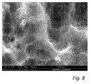
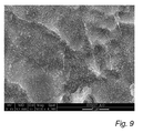
- the surface structure obtained after step c is shown in Figs. 8 and 9 and will be described in more detail below.
- metallic oxide originating from the dissolution of modified metallic oxide obtained in step b precipitates to form a secondary nanostructure comprising uniformly distributed rounded peaks on top of the microstructure and the primary nanostructure.
- the peaks of the secondary nanostructure thus consist of metallic oxide.
- Soluble metal compounds may also be separately added to the aqueous composition of step c in order to increase the metal concentration of the step c composition.
- the compositions used in step b and step c may comprise a bone-growth enhancing material.
- the bone-growth enhancing material may comprise metal ions, such as titanium ions, magnesium ions, calcium ions, litium ions and/or strontium ions, or a salt thereof. These ions may be separately added to the composition.
- either the composition of step b or the composition of step c may comprise any of the above metal ions.
- both compositions may comprise metal ions.
- both compositions may comprise metal ions.
- they may comprise the same species or different species of metal ions.
- a modified surface may be obtained comprising said ions and/or salt(s) thereof, which has altered chemical properties.
- the biocompatibility of the component may be improved and the osseointegration of the component may be stimulated.
- both the compositions of step b and step c, or the composition of step b only comprise(s) ionized lithium or strontium or a combination thereof.
- only the composition of step c comprises ionized lithium or strontium or a combination thereof.
- a bone-growth enhancing material such as ionized lithium or strontium, may be applied on the surface of the component after the performance of step b or step c according to the invention.
- the invention relates to a biocompatible component obtainable by the method described above, and to a method for implanting the biocompatible component into the body of a human or an animal.
- the biocompatible component may be implanted into a periodontal area of the body of a human or an animal.
- the invention in another aspect, relates to a biocompatible component having a hierarchical surface structure comprising a microstructure, a primary nanostructure superimposed on said microstructure and optionally a secondary nanostructure superimposed on said primary nanostructure.
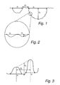
- the terms “depth” (h 1 ), “diameter” (x 1 ) and “distance” (D 1 ) in respect of a profile of the microstructure are defined in Fig. 1 .
- the depth (h 1 ) of a pit is defined as the distance between an imaginary line drawn between two adjacent peaks and the intermediate surface at its lowest point. If no well-defined peaks are present, the imaginary line is drawn between those points where the surface profile starts to deviate from an essentially flat surface profile (a plateau).
- the diameter (x 1 ) of a pit and the distance (D 1 ) between adjacent pits are the distances between said adjacent points as defined in Fig. 1 .
- a superimposed primary nanostructure is also schematically provided on the microstructure.
- the terms “depth” (h 2 ) and “diameter” (x 2 ) in respect of the primary nanostructure are correspondingly defined in Fig. 2 .
- the terms “height” (h 3 ), “diameter” (x 3 ) and “peak-to-peak distance” in respect of the secondary nanostructure are defined in Fig. 3 .
- the peak height is defined as the the distance between an imaginary line drawn between two adjacent peaks and the intermediate surface at its lowest point.
- the peak diameter (x 3 ) is measured between those points of the peak where the surface profile starts to deviate from an essentially flat surface profile.
- the angle ⁇ in respect of a profile of the microstructure and the angle ⁇ in respect of a profile of the primary nanostructure are defined.
- the angle ⁇ is defined as the angle between two imaginary lines, one of which representing the slope of a wall of a pit of the microstructure at the point where the surface profile starts to deviate from an essentially flat surface profile (P 1a ), and one of which representing the slope of an adjacent wall of an adjacent pit of the microstructure at the point where the surface profile starts to deviate from an essentially flat surface profile (P 1b ).
- Said mutually adjacent pits may thus be separated by a plateau. Accordingly, in the case where two adjacent pits are separated by a peak, the imaginary lines represent the inclinations of the walls at said peak.
- the angle ⁇ is defined as the angle between two imaginary lines representing the slope of a wall of a depression of the primary nanostructure at its infection point (P 2a ) and the slope of an adjacent wall of an adjacent depression of the primary nanostructue at its inflection point (P 2b ), respectively. In the case where two concave depressions are separated by a peak, the inflection point is thus located at said peak.
- step b provides a modified oxide surface which is thickened, reactive, and has a white or whitish colour.
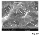
- Fig. 5a is a SEM image of a component after step b of the method of the invention showing said microstructure and said primary nanostructure. The component was pretreated by blasting. As is seen in this image, the microstructure comprises pore-like depressions or pits of different sizes.
- Fig. 5b is a SEM image of a component after step b according to the invention in which the diameters of some of the pits of the microstructure have been marked.
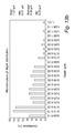
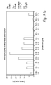
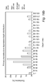
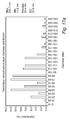
- Fig. 13 and 14 present the distributions of pit diameter, pit depth and distance between mutually adjacent pits of the microstructure.
- a pit of the microstructure may have a diameter x 1 in the range of from 0.5 to 15 ⁇ m, preferably from 1 to 10 ⁇ m, and more preferably from 1 to 5 ⁇ m; and a depth h 1 in the range of 0.1 to 2.5 ⁇ m, preferably from 0.1 to 1 ⁇ m, and more preferably from 0.1 to 0.7 ⁇ m.
- Adjacent pits are typically separated by a plateau or a ridge, which may have a diameter of up to 10 ⁇ m, preferably up to 5 ⁇ m, and more preferably up to 3 ⁇ m.
- the distance D 1 between adjacent pits may be up to 10 ⁇ m, up to 5 ⁇ m, or up to 3 ⁇ m. However, as is often the case with a separating ridge, two adjacent pits may be considered not to be separated by any distance at all.
- the general shape of an individual pit of the microstructure may be roughly circular or oval, or it may be irregular.
- the microstructure may also comprise undercuts.
- a pit of a larger diameter may comprise one or several pits of a smaller diameter.
- the microstructure may have an angle ⁇ as defined above and in Fig. 4 in the range of from 20° to 130°; preferably from 30° to 120°, more preferably from 40° to 110°, and most preferably from 50° to 100°.
- the primary nanostructure may be seen in Fig. 5 , and is further illustrated in Fig. 6 , in which elements of the primary nanostructure have been marked.
- the primary nanostructure may be described as a wave-like continuous structure.
- the primary nanostructure comprises a multitude of shallow depressions in the walls and bottoms of the pits of the microstructure and in the plateaus and/or ridges separating the pits of the microstructure.
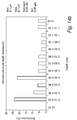
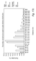
- the diameter x 2 of the depressions of the primary nanostructure may be in the range of from 10 nm to 1 ⁇ m, preferably from 10 nm to 600 nm, and more preferably from 10 nm to 500 nm; and the depth h 2 of the depressions of the primary nanostructure may be in the range of 10 to 300 nm, preferably from 30 to 150 nm.
- the depressions are shallow, meaning that the diameter of a depression exceeds the depth thereof.
- the depressions of the primary nanostructure have an essentially circular or oval shape. Fig. 15 and 16 present the diameter and depth distributions of the depressions of the primary nanostructure.
- the depressions of the primary nanostructure may have a distinct boundary or edge. However, a depression of the primary nanostructure may also have a wall which rises from the bottom of said depression and then softly passes into the next depression without forming a distinct boundary therebetween. In either of the above cases, however, there is no definable distance separating the boundary of a depression of the primary nanostructure from the boundary of another depression. Rather, the depressions are juxtaposed to form a wave-like pattern having a quite regular aspect.
- the primary nanostructure may have an angle ⁇ as defined above and in Fig. 4 in the range of from 80° to 160°; preferably from 90° to 150°, more preferably from 100° to 140°, and most preferably from 110° to 130°.
- the primary nanostructure is superimposed on the primary microstructure. Furthermore, the diameter and depth, respectively, of a primary nanostructure each is smaller than the corresponding dimension of an individual pit of the microstructure.
- an individual pit of the microstructure typically comprises multiple depressions of the primary nanostructure.
- a pit of the microstucture may comprise from about 5 to about 50 of said depressions.
- a part of a boundary of a depression of the primary nanostructure typically constitutes a part of a boundary of another depression of the primary nanostructure.
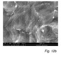
- Fig. 8 and Fig 9 are SEM images of a modified component according to the invention.
- the sample was pretreated by blasting, whereas in Fig. 9 , the sample was simply machine worked.
- a secondary nanostructure which is superimposed on the above-mentioned microstructure and primary nanostructure can be seen.
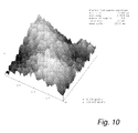
- Fig 10 is an image taken by atomic force microscopy (AFM) further illustrating the secondary nanostructure.
- the secondary nanostructure comprises discrete projecting elements having the shape of rounded peaks.
- the nanopeaks are densely and uniformly distributed on the underlying surface structure.
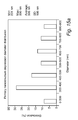
- the number of peaks per unit area may be in the range of from 15 to 150 peaks/ ⁇ m 2 , and preferably from 50 to 130 peaks/ ⁇ m 2 .
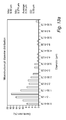
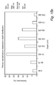
- Fig. 17 presents the peak diameter, the average peak height and the peak-to-peak distance distributions of the secondary nanostructure
- the average peak height h 3 of the secondary nanostructure is in the range of from 5 to 200 nm, and preferably from 5 to 100 nm.
- the diameter x 3 of an individual peak of the secondary nanostructure typically is in the range of from 20 to 550 nm, and preferably from 20 to 150 nm.
- the peak-to-peak distance D 3 typically is in the range of from 10 to 450 nm, and preferably from 40 to 200 nm.
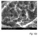
- Fig. 11 presents a SEM image of a component comprising the microstructure, the primary nanostructure and the secondary nanostructure, wherein pits of the microstructure have been marked.
- a superior surface structure exists on which the microstructure is superimposed.
- the surface structure of a component of the invention pretreated by blasting typically comprises large pits having a length in the range of from 10 to 70 ⁇ m and a depth in the range of from 3 to 20 ⁇ m.
- the large pits typically have a generally oval shape.
- the distance between adjacent pits may be in the range of from 1 to 20 ⁇ m.
- Superimposed on this large pit structure is the microstructure mentioned above.
- the sides and bottoms of the large pits and the surfaces between the large pits comprise the pits and the separating plateaus and/or ridges of the above mentioned microstructure.
- a SEM image of a conventional blasted surface is presented in Fig. 7 .
- a blasting pretreatment affects the dimensions of the subsequently formed microstructure, primary nanostructure and optional secondary nanostructure.
- the subsequently formed microstructure In a component according to the invention which was subjected to blasting, the subsequently formed microstructure generally had somewhat larger dimensions than the microstructure of a component according to the invention which was simply machine worked, and the subsequently formed primary nanostructure generally had somewhat smaller dimensions than the primary nanostructure of a component according to the invention which was simply machine worked.
- the diameters of both the microstructure and the primary nanostructure, and the depths of the microstructure were more uniform in a blasted component, as is demonstrated by the standard deviation values shown in Table 1, than the corresponding features of a machine worked component.
- the invention in another aspect, relates to a method for implanting a biocompatible component into the human or animal body.
- the method comprises the step of i) providing a biocompatible component as described above, and ii) implanting the component into the body of a human or an animal.
- the biocompatible component may be implanted in a periodontal area of said body of a human or an animal.
- Titanium samples having the shape of a coin (machine worked and blasted, respectively), a fixture (blasted) and an abutment (machine worked) were cleaned by a conventional chemical treatment.
- the samples were immersed in an 1 M aqueous solution of oxalic acid and left at 80°C for 30 minutes under vigorous agitation. After 30 minutes the samples were removed from the oxalic acid solution and rinsed in water followed by rinsing in water in an ultrasonic bath for 2 minutes. Approximately 10 minutes after rinsing, the samples were immersed in 0.1 M aqueous solution of HF at room temperature and agitation until the start of active dissolution, followed by an additional active treatment time of 40 seconds. Next, the samples were removed from the HF solution and rinsed in water followed by rinsing in water in an ultrasonic bath for 5 minutes. The samples were dried in air at room temperature for about 60 minutes before sterilization.
- SEM Scanning electron microscopy
- FEI ESEM XL 30
- Stereo images using magnifications between 500x and 15000x were taken and evaluated by the MeX 5.0 programme (Alicona). No filters were used. Depths and diameters of the pits of the microstructure and the depressions of the primary nanostructure and distances between adjacent pits of the microstructure were determined. The results are presented in Fig. 13a-c (machine worked sample) and Fig. 14a-c (blasted sample) for the primary microstructure and in Fig. 15 a-b (machine worked sample) and Fig.
- TappingMode TM atomic force microscopy was performed using a Nanoscope IIIa instrument (Digital Instruments).
- the secondary nanostructure of three samples according to the invention (machine worked) were analysed at two points per sample, each point located approximately 1 mm from the sample edge.
- the area of analysis was 2 ⁇ m x 2 ⁇ m.
- Peak heights, peak diameters, peak-to-peak distances and the number of peaks/ ⁇ m 2 were determined. Said dimensions were measured in mm and converted to nm using the scale provided in the profile plots obtained.
- the distributions of peak height, peak diameter and peak-to-peak distance, respectively, are presented in Fig. 17a-c .
- Table 1 summarizes the maximum, minimum and average values of the dimensions determined for the microstructure and primary nanostructure for blasted and machine worked components, respectively, determined by SEM/MeX 5.0. The maximum, minimum and average values determined for the secondary nanostructure of a machine worked component by AFM are also presented. Table 1. Surface structure dimensions for blasted and machine worked samples according to the invention.
- Blasted titanium samples (coin-shaped) were immersed in an aqueous solution comprising 0.1 M hydrofluoric acid and 1 M oxalic acid at room temperature and agitation for 5, 15, 30 and 42 minutes, respectively.
- the samples were removed from the solution and rinsed in water followed by rinsing in water in an ultrasonic bath for 2 minutes. After drying of the samples, the surface topography was examined by scanning electron microscopy (ESEM XL 30, FEI).
- Titanium samples were immersed in a 0.1 M aqueous solution of HF at room temperature and agitation until the start of active dissolution, followed by an additional treatment time of 40 s. Next, the samples were removed from the HF solution and rinsed in water followed by rinsing in water in an ultrasonic bath for 5 minutes. Approximately 10 minutes after rinsing the samples were immersed in an 1 M aqueous solution of oxalic acid and left at 80°C for 30 minutes under vigorous agitation. After 30 minutes the samples were removed from the oxalic acid solution and rinsed in water followed by rinsing in water in an ultrasonic bath for 2 minutes. The samples were allowed to dry for 1 hour at room temperature.
- ALP alkaline phosphatase
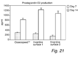
- PGE2 prostaglandin E2
- MG-63 is a human cell line conventionally used for in vitro studies of osteoblasts.
- MG-63 cells (MG-63, ATCC No CRL-1427, U. S.) were grown in 300 ml Falcon cell culture flasks (BD, WWR, Sweden) in Dulbecco's Minimun Essential Medium (D-MEM) (Gibco, UK) containing 5 % fetal calf serum (FCS; Gibco, UK) and 1 % penicillin-streptomycin (PEST; Gibco, UK) from second passage from an ampulla of frozen cells.
- D-MEM Dulbecco's Minimun Essential Medium
- FCS fetal calf serum
- PEST penicillin-streptomycin
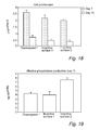
- the samples according to the invention induced a lower cell density and a lower number of adherent cells compared to reference surfaces.
- a higher number of cells were proliferative compared to cells grown on the reference surfaces.
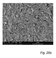
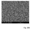
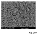
- Cells grown on the surfaces according to the invention were also less apoptotic, more elongated and had many small projections indicating activity, as is seen in Fig 20a-c .
- the invention provides a biocompatible component which is improved in respect of bone formation rate and osseointegration.
Abstract
The invention relates to a method for modification of a biocompatible component comprising the steps of a) providing a biocompatible component at least partly covered by metallic oxide; and b) treating at least a part of said component, which part is covered by said metallic oxide, with an aqueous composition comprising oxalic acid; whereby a modified metallic oxide is obtained. The invention also relates to a biocompatible component comprising a substrate having a surface comprising a) a microstructure comprising pits separated by plateus and/or ridges; and b) a primary nanostructure being superimposed on said microstructure, said primary nanostructure comprising depressions arranged in a wave-like formation.
Description
- The present invention relates to a biocompatible component which has improved properties for implantation into bone tissue.
- For implanting orthopaedic or dental implants, generally metallic implants, into bone tissue, a one-stage procedure is nowadays often used. In the one-stage procedure, a first implant part, such as a dental fixture, is generally surgically placed into the bone tissue, and a healing cap or a secondary implant part, such as an abutment, is then attached to the first implant part directly after the surgical operation. The soft tissue is then allowed to heal around the healing cap or the secondary implant part. When a healing cap is used, the cap is removed after a few weeks or months without any surgical procedure, and secondary implant parts, such as an abutment and a provisional crown, are attached to the first implant part. The one-stage procedure is for instance described in L Cooper et al: "A multicenter 12-month evaluation of single-tooth implants restored 3 weeks after 1-stage surgery", The International Journal of Oral & Maxillofacial Implants, ).
- The two-stage procedure, which in some dental cases still is preferable, generally involves in a first stage surgically placing a first implant part, such as a dental fixture, into the bone tissue, where it is allowed to rest unloaded and immobile for a healing period, often of three months or more, in order to allow the bone tissue to grow onto the implant surface to permit the implant to be well attached to the bone tissue, the cut in the soft tissue covering the implant site being allowed to heal over the implant. In a second stage, the soft tissue covering the implant is opened and secondary implant parts, such as a dental abutment and/or a restoration tooth, are attached to the first implant part, such as said fixture, forming the final implant structure. This procedure is for instance described by Brånemark et al: "Osseointegrated Implants in the Treatment of the Edentulous Jaw, Experience from a 10-year period", Almquist & Wiksell International, Stockholm, Sweden.
- However, the fact that the implant not should be loaded during the healing period means that the secondary implant parts may not be attached to the first implant part and/or used during the healing period. In view of the discomfort associated with this, it is desirable to minimize the time period necessary for the above-mentioned first stage or even perform the entire implantation procedure in a single operation, i.e. to use the one-stage procedure.
- For some patients, it might be considered better to wait at least three months before functionally loading the implant, both for one- and two-stage procedures. However, an alternative using the one-stage procedure is to put the implant in function directly after implantation (immediate loading) or a few weeks after implantation (early loading). These procedures are, for instance, described by D M Esposito, pp 836-837, in Titanium in Medicine, Material Science, Surface Science, Engineering, Biological Responses and Medical Application, Springer-Verlag (2001).
- It is essential that the implant establishes a sufficient stability and bond between implant and bone tissue to enable the above disclosed immediate or early loading of the implant. It shall also be noted that an immediate or early loading of the implant may be beneficial to bone formation.
- Some of the metals or alloys, such as titanium, zirconium, hafnium, tantalum, niobium, or alloys thereof, that are used for bone implants are capable of forming a relatively strong bond with the bone tissue, a bond which may be as strong as the bone tissue per se, and sometimes even stronger. The most notable example of this kind of metallic implant material is titanium and alloys of titanium whose properties in this respect have been known since about 1950. The bond between the metal and the bone tissue has been termed "osseointegration" (Albrektsson T, Brånemark P I, Hansson H A, Lind-ström J, "Osseointegrated titanium implants. Requirements for ensuring a long-lasting, direct bone anchorage in man", Acta Orthop Scand, 52:155-170 (1981)).
- It may be noted that in contact with oxygen, titanium, zirconium, hafnium, tantalum, niobium and their alloys are instantaneously covered with a native oxide. This native oxide on titanium implants mainly consist of titanium(IV) dioxide (TiO2) with minor amounts of Ti2O3, TiO and Ti3O4.
- Although the bond between the (oxidised) metal, e.g. titanium, and the bone tissue may be comparatively strong, it is desirable to enhance this bond.
- There are to date several methods for treating metallic implants in order to obtain a better attachment of the implant, and thus improved osseointegration. Some of these involve altering the morphology of the implant, for example by creating irregularities on the implant surface in order to increase the surface roughness in comparison to an untreated surface. It is believed that an increased surface roughness, which gives a larger contact and attachment area between the implant and the bone tissue, provides a better mechanical retention and strength between implant and bone. It is well-known within the art that a surface roughness can be provided by, for example, plasma spraying, blasting or acid etching.
- Furthemore, it is known that osteoblasts, i.e, bone-forming cells, sense and react to multiple chemical and physical features of the underlying surface. Formation of bone at an implant surface requires the differentiation of precursor cells into secretory osteoblasts to produce unmineralised extracellular matrix (ECM), and the subsequent calcification of this matrix, as described in for instance Anselme K, Osteoblast adhesion on biomaterials, Biomaterials 21, 667-681 (2000).
- Alteration of the chemical properties of the implant surface has frequently been used for achieving a better attachment of the implant to the bone tissue. Several methods involve the application of a layer of ceramic material, such as hydroxyapatite, on the implant surface in order to improve the bonding of the implant to bone since hydroxyapatite is chemically related to bone.
US 7,169,317 (Beaty) discloses a method for preparing the surface of a bone implant which comprises the removal of the native oxide from the implant surface, acid etching or otherwise treating the resulting implant surface to produce a substantially uniform surface roughness, and depositing discrete particles of a bone-growth enhancing material such as hydroxyapatite, bone minerals and bone morphogenic proteins thereon. The etching and deposition steps are preferably performed in the absence of unreacted oxygen by using an inert atmosphere. - A common disadvantage with coatings comprising hydroxyapatite is, however, that they may be brittle and may flake or break off from the implant surface due to a stronger bond being formed between the bone and coating than between the coating and the implant, which may lead to an ultimate failure of the implant. Regarding the use of protein coatings, there are additional aspects to consider. Due to the chemical nature of proteins, a surface having a protein coating may require specific sterilization and storage conditions in order to maintain its biological activity. In addition, host tissue response (e.g. immunological response) to biomolecules such as proteins may be unpredictable. Another disadvantage of the method of
US 7,169,317 is the requirement for a surface free of oxide, considering that working in an inert atmosphere is inconvenient and requires specialized equipment. -
US 2007/01100890 US 2007/0112353 andWO 2007/050938 (Berckmans III et al ) aim at solving the problem of poor adherence of a ceramic coating to the implant and disclose a method of depositing discrete nanoparticles on a roughened implant surface through a process of exposing the implant surface to a solution comprising 2-methoxyethanol solvent and hydroxyapatite (HA) nanocrystals, e.g. in the form of a colloid. The HA nanocrystals are deposited to form a nanostructure which is intended to promote the osseointegration of the implant. However, one negative aspect of this method is the formulation of the nanocrystal-containing composition requiring organic solvents, which may be undesirable due to the risk of organic contamination of the surface, and several processing steps using advanced equipment. The deposition is performed at room temperature, requiring incubation times of 1 to 4 hours. - The roughness of an implant surface has been shown to affect cell proliferation and also the local production of growth factors by the cells around an implant. In vitro studies of human osteoblasts have shown that surfaces of increased microscale roughness resulted in a reduced number of cells, lower cell proliferation and increased matrix production, compared to smoother surfaces (Martin J Y et al, Proliferation, differentiation, and protein synthesis of human osteoblast-like cells (MG63) cultured on previously used titanium surfaces, Clin Oral Implants Res, Mar 7(1), 27-37, 1996). Yet other studies have shown that surface roughness enhances cell differentiation, while reducing cell proliferation (Kieswetter K, Schwartz Z, Hummert T W, Cochran D L, Simpson J, Dean D D, Boyan B D, Surface roughness modulates the local production of growth factors and cytokines by osteoblast-like MG-63 cells, J Biomed Mater Res, Sep., 32(1), 55-63, 1996). Increased cell differentiation implies a potentially improved rate of bone formation.
- Recently, the modulation of adhesive capabilities of cells have advanced from micro to nanopatterning techniques. It is believed that cell function may be regulated by nanostructural physical signals by stimulating integrin-mediated focal adhesion and intracellular signaling in anchorage-dependent cell function (Bershadsky A, Kozlov M, and Geiger B, Adhesion-mediated mechanosensitivity: a time to experiment, and a time to theorize, Curr Opin Cell Biol, 18(5), 472-81, 2006).
-
EP 1440669B1 and relatedUS 2004/0153154 A1 (Dinkelacker) disclose a bone implant having a surface which is reshaped to comprise a microstructure for anchoring the implant in the cell area. The microstructure, which is provided in the form of a cover layer applied on a previously roughened surface, comprises an array of densely packed rounded domes separated by rounded lacunae, the dimensions of the microstructure being approximately the same order of magnitude as the dimensions of the cells. The microstructural cover layer may be applied e.g. by sputtering. Further, a nanostructure, also obtained by sputtering, comprised of rounded domes separated by rounded lacunae is provided on the microstructure, wherein the dimensions of the nanostructure is approximately one decimal order of magnitude smaller than the corresponding dimensions of the microstructure. Again, however, there are potential problems with the stability of the cover layer and the integrity of the attachment between the cover layer and the implant body. Another technique for creating a desirable surface roughness is disclosed inEP 1 449 544 A1 (Wen et al - In brief, although there are today many existing techniques for improving the osseointegration of an implant, these methods generally suffer from drawbacks in respect of processability, cost-efficiency and biological effect and stability after implantation. Thus, there is a need in the art for improvement in the production of implants which have properties which even further promote osseointegration.
- An object of the invention is to provide a biocompatible component having a desired rate of attachment between bone tissue and the component upon implantation thereof in bone tissue, and forming a mechanically strong bond with said bone tissue.
- Another object of the invention is to provide a method for producing such a biocompatible component.
- The passivating oxide normally covering titanium, zirconium, hafnium, tantalum, niobium and alloys thereof to a large extent provides the biocompatibility of these metals by preventing any chemical interaction between the metal and living tissue. However, by causing small defects in the oxide structure, the biocompatibility of metallic components may actually be further increased. The inventors have found that by treating a component having a metallic oxide surface by oxalic acid, a modified surface structure of the component is obtained, which has improved properties for implantation into living bone.
- Thus, in one aspect, the present invention relates to a method for modification of a biocompatible component comprising the steps of
- a) providing a biocompatible component at least partly covered by metallic oxide; and
- b) treating at least a part of said component, which part is covered by said metallic oxide, with an aqueous composition comprising oxalic acid,
- The component obtained by the inventive method has a hierarchical surface topography comprising a microstructure and a primary nanostructure superimposed on said microstructure, which has been found to increase the activity of bone-forming cells adhered thereto.
- Esthetics becoming an increasingly important aspect of implantology, conventional titanium dental implants present an obstacle to a perfect esthetic solution, as the metallic grey lustre of a conventional titanium oxide surface may be visible through a patient's gingiva. Advantageously, the modified oxide surface obtained by the inventive method has a whitish colour, which is lighter and duller than the metallic grey colour of the surface of the component before treatment according to the invention. The whitish colour is very desirable for a dental component, as a natural-looking implant may be obtained. The whitish colour is best seen in a blasted component. The altered colour of the component may also be used as an indication that step b has been completed.
- The concentration of oxalic acid in the composition of step b may be in the range of from 0.001 to 5 M, preferably about 1 M; and the treatment time of step b is in the range of from 10 to 60 minutes, preferably in the range of from 20 to 40 minutes, and more preferably about 30 minutes. The temperature of the composition of step b is typically in the range of from about 20 °C to about 100°C; preferably in the range of from 60 °C to 90 °C; and more preferably about 80 °C.
- Optionally the above method further comprises the step of
- c) treating at least part of said modified oxide with a second aqueous composition comprising
- i) at least one material selected from the group comprising ionized fluorine and ionized chlorine; and
- ii) at least one acid.
- In particular, step c should be performed before a passivating oxide is formed on said modified metallic oxide. By performing step c before the modified oxide obtained in step b is covered by a passivating oxide, a surface having a uniformly distributed secondary nanostructure may be obtained, which promotes the osseointegration of the component. Thus, when the component is kept at a temperature above 0 °C, e.g., room temperature, at normal atmospheric pressure and in an oxygen-containing atmosphere, the interval between step b and step c is preferably as short as possible to avoid the formation of passivating oxide on the surface of the component. Under such conditions, step c may be performed within 180 hours or less after the completion of step b, for example 72 hours, 36 hours, 24 hours or 1 hour after step b. Preferably, step c is performed within 30 minutes or less after the completion of step b, and more preferably within 10 or minutes less after the completion of step b.
- The second aqueous composition may have a pH in the range of from 0.5 to 5, preferably from 1 to 3, and more preferably about 2; and the concentration of ionized fluorine and/or chlorine may be in the range of from about 0.05 to 0.5 M, preferably about 0.1 M. The active treatment time of step c is in the range of from 10 seconds to 60 minutes, preferably in the range of from 10 seconds to 3 minutes, and more preferably in the range of from 10 seconds to 50 seconds. The temperature of the composition of step c is typically in the range of from 15 to 25 °C; and preferably in the range of from 18 to 23 °C.
- The inventive method uses aqueous solutions only, thus avoiding problems related to organic solvents, such as organic residues remaining on the surface of the component. The aqueous solution which is used in step c preferably comprises hydrofluoric acid.
- The method also uses simple equipment, is easily performed and is robust. Thus, the method according to the invention is cost-efficient and suitable for industrial applicability. Furthermore, the treatment time is advantageously short.
- Further, the osseointegration of the component may be enhanced by including a bone-growth enhancing material in the surface of the component. This surface may for example be achieved by including metal ions or salt thereof, which metal ions may be selected from the group consisting of titanium ions, magnesium ions, calcium ions, lithium ions, strontium ions or any combination thereof, into the aqueous compositions of step b and/or step c. In particular, the inventors have found that lithium or strontium ions locally administered in bone tissue have a local effect on the bone formation and bone mass in said bone tissue. It has further been found that an implant comprising a surface oxide containing and/or releasing ionized lithium or strontium provides an improved rate of bone formation in comparison to an implant comprising a surface oxide layer containing, for instance, ionized calcium or magnesium. Thus, the composition of step b and/or the composition of step c may comprise lithium and/or strontium or a salt thereof. In order to provide a favourable substrate for osseointegration, the biocompatible component preferably at least partly consists of titanium or a titanium alloy. Accordingly, said metallic oxide preferably comprises titanium oxide. The metallic oxide may consist essentially of a titanium oxide or a combination of titanium oxides. The metallic oxide may be passivating titanium oxide.
- In order to provide the component with a desirable initial surface roughness or desirable chemical characteristics, the bio-compatible component may be subjected to a mechanical and/or chemical surface treatment prior to step b. A chemical treatment may for example comprise a cleaning process to remove undesired substances which may negatively affect the result of the method of the invention or the bio-compatibility of the component. A roughening treatment, such as blasting, may further enhance the osseointegration of the component and improve the biomechanical properties thereof.
- In another aspect, the invention relates to a component which is obtainable by a method as described above.
- The inventors have found that a surface having a hierarchical surface topography comprising a microstructure and a primary nanostructure superimposed on said microstructure provides an implant surface which is improved in respect of osseointegration and biomechanical interaction with bone tissue. Thus, in another aspect, the invention relates to a biocompatible component, comprising a substrate having a surface comprising
- a) a microstructure comprising micropits separated by plateus and/or ridges; and
- b) a primary nanostructure being superimposed on said microstructure, said primary nanostructure comprising depressions arranged in wave-like formation.
- The inventors have found that the above surface promotes osteoblast differentiation and secretion of bone precursor material. The microstructure provides an underlying microroughness comprising pore-like pits, resembling cell culture dishes, which stimulate cells to proliferate and differentiate. Possibly, the surface topography comprising the microstructure and the primary nanostructure resembles the topology of a site in living bone where bone resorption has occurred. It is believed that the surface topography of the component of the invention fits the expectations of pre-osteoblast cells present around an implant site, and by mimicking the surface of natural bone prepared by osteoclasts for bone remodeling, osteoblast activity may be quickly and strongly induced by a component according to the invention.The microstructure may have a pit diameter in the range of from 0.5 to 15 µm, and preferably from 1 to 10 µm; and a depth in the range of from 0.1 to 2.5 µm, and preferably from 0.1 to 1 µm. The distance between adjacent micropits may be up to to 10 µm. The depressions of the primary nanostructure have a diameter in the range of from 10 nm to 1 µm, preferably in the range of from 10 nm to 600 nm, and more preferably in the range of from 10 nm to 500 nm. The depth may be in the range of from 10 nm to 300 nm, and is typically in the range of from 30 to 150 nm. Furthermore, the diameter of an individual depression of the primary nanostructure typically exceeds the depth of the same depression.
- As mentioned above, the primary nanostructure is superimposed on the primary microstructure. Furthermore, the diameter and depth, respectively, of a primary nanostructure each is smaller than the corresponding dimension of an individual pit of the microstructure. Thus, an individual pit of the microstructure typically comprises multiple depressions of the primary nanostructure. Furthermore, a boundary of a depression of the primary nanostructure typically constitutes a boundary of another depression of the primary nanostructure.
- Furthermore, the above described surface may further comprise a secondary nanostructure comprising discrete nanoelements being superimposed on said primary nanostructure in a uniformly distributed pattern and having the shape of rounded projections. The secondary nanoelements, it is believed, improve the anchoring of the cells to the underlying surface and further stimulate cell activity.
- The secondary nanostructure of the biocompatible component of the invention may have a peak diameter in the range of from 20 to 550 nm, preferably from 20 to 150 nm; and an average peak height of from 5 to 200 nm, preferably from 5 to 100 nm. The peak-to-peak distance is typically in the range of from 10 to 450 nm, and preferably from 40 to 200 nm. The peak density is typically in the range of from 15 to 150 peaks/µm2, and preferably from 50 to 130 peaks/µm2.
- At a bone tissue-bone implant interface, a tissue layer generally forms which contains a reduced amount of collagen and minerals, and thus has a decreased strength compared to normal, healthy bone. The thickness of this tissue layer determines the mechanical stength of the bone-implant interface (Albrektsson, T et al, Ultrastructural analysis of the interface zone of titanium and gold implants, Advances in Biomaterials 4, 167-177, 1982; Albrektsson, T et al, Interface analysis of titanium and zirconium bone implants, Biomaterials 6, 97-101, 1985; Albrektsson T, Hansson, H-A, An ultrastructural characterization of the interface between bone and sputtered titanium or stainless steel surfaces, Biomaterials 7, 201-205, 1986; Hansson, H-A et al, Structural aspects of the interface between tissue and titanium implants, Journal of Prosthetic Dentistry 50, 108-113, 1983; Johansson, C et al, Ultrastructural differences of the interface zone between bone and Ti6A14V or commercially pure titanium, Journal of Biomedical Engineering 11, 3-8, 1989; Johansson, C. et al, Qualitative, interfacial study between bone and tantalum, niobium or commercially pure titanium, Biomaterials 11, 277-280, 1990; Sennerby, L et al, Structure of the bone-titanium interface in retrieved clinical oral implants, Clinical Oral Implants Research 2, 103-111, 1991; Sennerby, L et al, Ultrastructure of the bone-titanium interface in rabbits, Journal of Materials Science: Material in Medicine 3, 262-271, 1992; Sennerby, L et al, Early tissue response to titanium implants inserted in rabbit cortical bone, Part II: Ultrastructural observations, Journal of Materials Science: Material in Medicine 4, 494-502, 1993) The hierarchical surface topography comprising the microstructure and the primary nanostructure provides an improved mechanical interaction between the component and the subsequently formed bone tissue, which is believed to result in the formation of a less thick tissue layer of reduced strength. The secondary nanostructure further improves the mechanical interaction between the biocompatible component and the surrounding bone tissue after implantation. Hence, the biocompatible component of the invention provides a bone tissue-implant interface of improved shear and tensile strength.
- Furthermore, in order to provide the component with a desired initial surface roughness or desired chemical characteristics, the substrate may be subjected to a mechanical and/or chemical surface treatment. A chemical treatment may for example comprise a cleaning process. A roughening treatment, such as blasting, may provide a surface structure in which the diameters and depths of the subsequently formed microstructure and the diameters of the primary nanostructure are less variable (i.e, having smaller standard deviation values). The increased homogeneousness of the surface of the component of the invention may further enhance the osseointegration of the component and improve the biomechanical properties thereof.
- The biocompatible component substrate typically at least partly consists of titanium or a titanium alloy. Preferably, the substrate consists of titanium. Furthermore, the secondary nanostructure may comprise metallic oxide, preferably titanium oxide. The homogeneouness of the component surface, which may consist of metallic oxide only, is very advantageous in respect of the long-term stability and integrity of the component after implantation. Additionally, the component surface structure is stable with respect to sterilization procedures and shelf storage.
- The osseointegration of the component of the invention may be further enhanced by comprising a bone-growth enhancing material, in the surface of the component. Such a surface may for example be achieved by including metal ions, for example those selected from the group consisting of titanium ions, magnesium ions, calcium ions, lithium ions, strontium ions or any combination thereof in the surface. In particular, the inventors have found that lithium or strontium ions locally administered in bone tissue may have a local effect on the bone formation and bone mass in said bone tissue. Thus, the surface of the component of the invention may comprise lithium and/or strontium or a salt thereof.
- The biocompatible component of the invention may be a dental component, for example an implant, a fixture, an abutment, or combinations thereof, such as a one-piece implant. The biocompatible component may also be an orthopaedic component, such as a hip joint component intended for implantation into the neck of the femur of a patient.
- In another aspect, the invention relates to a method for implanting a biocompatible component into the human or animal body comprising the steps of
- i) providing a biocompatible component according to the above description; and
- ii) implanting said biocompatible component into the body of a human or an animal.
-
-
Fig. 1 is a schematic illustration defining the parameters used in respect of the microstructure. -
Fig. 2 is a schematic illustration defining the parameters used in respect of the primary nanostructure. -
Fig. 3 is a schematic illustration defining the parameters used in respect of the secondary nanostructure. -
Fig. 4 is a schematic illustration defining the angles used in respect of the microstructure and the primary nanostructure, respectively. -
Fig. 5a is a scanning electron microscopy image of a titanium sample according to the invention. -
Fig. 5b is a scanning electron microscopy image of a titanium sample according to the invention, wherein diameters of the microstructure are marked. -
Fig. 6a is a scanning electron microscopy image of a titanium sample according to the invention, wherein depressions of the primary nanostructure are marked. -
Fig. 6b is a scanning electron microscopy image of a titanium sample according to the invention, wherein diameters of the primary nanostructure are marked. -
Fig. 7 is a is a scanning electron microscopy image of a titanium sample subjected to a conventional blasting technique. -
Fig. 8 is a scanning electron microscopy image of a blasted titanium sample according to the invention. -
Fig. 9 is a scanning electron microscopy image of a titanium sample according to the invention. -
Fig. 10 is an atomic force microscopy 3D image of a titanium sample according to the invention. -
Fig. 11 is a scanning electron microscopy image of a blasted titanium sample according to the invention, wherein elements of the microstructure are marked. -
Fig. 12a-b are scanning electron microscopy images of a titanium reference sample treated in a mixture of hydrofluoric acid and oxalic acid. -
Fig. 12c is a scanning electron microscopy image of a titanium sample treated in hydrofluoric acid and subsequently in oxalic acid. -
Fig. 13a-c are graphs showing the distribution of microstructure pit diameter, depth and distance between adjacent pits, respectively, in a titanium sample according to the invention. -
Fig. 14a-c are graphs showing the distribution of microstructure pit diameter, depth and distance between adjacent micropits, respectively, in a blasted titanium sample according to the invention. -
Fig. 15a-b are graphs showing the distribution of primary nanostructure depression diameter and depth, respectively, in a titanium sample according to the invention. -
Fig. 16a-b are graphs showing the distribution of primary nanostructure depression diameter and depth, respectively, in a blasted titanium sample according to the invention. -
Fig. 17a-c are graphs showing the distribution of secondary nanostructure peak diameter, height and peak-to-peak distance, respectively, in a titanium sample according to the invention. -
Fig. 18 is a graph showing the proliferation of cells grown for 7 days on a commercial titanium implant surface and on surfaces according to the invention, respectively. -
Fig. 19 is a graph showing the production of alkaline phosphatase after 7 days of cell cultivation on a commercial titanium implant surface and on surfaces according to the invention, respectively. -
Fig. 20a is a scanning electron microscopy image of cells grown for 36 hours centrally on a commercial implant surface. -
Fig. 20b is a scanning electron microscopy image of cells grown for 36 hours on a surface of a component according to the invention. -
Fig. 20c is a scanning electron microscopy image of cells grown for 36 hours on a surface of a component according to the invention. -
Fig. 21 is a graph showing the production of prostaglandin E2 after 7 and 14 days of cell cultivation on a commercial titanium implant surface and on surfaces according to the invention, respectively. - As used herein, the term "biocompatible component" includes within its scope any component which is intended for long-term or short-term contact with living tissue and which, upon said contact, does not evoke significant adverse biological reaction of the tissue. One example of a biocompatible component is an implant, such as a dental implant.
- As used herein the term "implant" includes within its scope any device of which at least a part is intended to be implanted into the body of a vertebrate animal, in particular a mammal, such as a human. Implants may be used to replace anatomy and/or restore any function of the body.
- Generally, an implant is composed of one or several implant parts. For instance, a dental implant usually comprises a dental fixture coupled to secondary implant parts, such as an abutment and/or a restoration tooth. However, any device, such as a dental fixture, intended for implantation may alone be referred to as an implant even if other parts are to be connected thereto.
- As used herein, the term "passivating (metallic) oxide" refers to naturally formed oxide, also referred to as native oxide, which is stable, does not grow substantially thicker over time and which prevents any substantial chemical reaction of the underlying substrate with an external agent. Passivating titanium oxide formed on titanium in contact with atmospheric oxygen generally has a thickness of 2-5 nm.
- As used herein, the term "bone-growth enhancing material" includes within its scope any substance which is capable of promoting bone formation, (e.g., promoting adhesion, proliferationand differentiation of osteoblasts or pre-osteoblasts; promoting the production of bone matrix components, secretion of bone matrix components, mineralisation of bone matrix; and inhibition of osteoclast activity), either alone or in combination with other substances.
- As used herein, the term "microstructure" refers to a physical structure of dimensions generally ranging from 0.5 µm to 100 µm, and the term "nanostructure" refers to a physical structure of dimensions generally ranging from 0.1 nm to 500 nm.
- The biocompatible component of the invention may be a dental component, for example an implant, a fixture, an abutment, or combinations thereof, such as a one-piece implant. The biocompatible component may also be an orthopaedic component, such as a hip joint component intended for implantation into the neck of the femur of a patient.
- The biocompatible component of the invention may consist of any suitable material, such as a metal, e.g. titanium or an alloy thereof, zirconium or an alloy thereof, hafnium or an alloy thereof, niobium or an alloy thereof, tantalum or an alloy thereof, a chromium-vanadium alloy or any combination of these materials, or a non-metal. The biocompatible component may be provided with a metallic layer, for example an applied metallic surface layer covering a non-metallic body or a body partly consisting of a non-metallic material. Examples of non-metallic materials comprise a ceramic, a plastic and a composite material.
- The metallic oxide may be a naturally air-formed oxide, or it may be formed in any kind of treatment prior to the method according to the invention.
- The biocompatible component may be subjected to any kind of pretreatment in order to create a desired substrate surface for further modification according to the inventive method. For example, the component may be pretreated by a mechanical, chemical or thermal treatment, or any combination thereof, to obtain a desired initial surface composition or roughness. A mechanical treatment may for instance comprise a blasting process. A chemical treatment may for instance comprise a cleaning or degreasing process.
- In one aspect, the present invention relates to a method for modification of a biocompatible component.
- According to the inventive method, at least a part of the biocompatible component is subjected to treatment with an aqueous composition comprising oxalic acid, whereby a modified metallic oxide is obtained (referred to as "step b"). In this treatment, the modified metallic oxide is dissolved and the underlying substrate is etched while new oxide is formed on the biocompatible component. The oxide dissolution and reoxidation processes occur simultaneously.
- The part of the biocompatible component to be treated is at least partly covered by said metallic oxide. In embodiments of the invention, step b is performed by placing the component in an aqueous solution of oxalic acid at an elevated temperature under vigorous agitation for a period of time. Alternatively, only part of the component may be immersed in the composition, e.g. by dipping. A part of the component not intended to be treated may be masked during the treatment.
- The pH of the composition of step b should be acidic, such as
pH 5 or below,pH 2 or below, or pH 0.7 or below. Preferably, the pH is as low as possible in view of processing convenience. - The aqueous composition comprising oxalic acid may be an aqueous solution comprising oxalic acid at a concentration in the range of from about 0.001 to about 5 M, e.g., a solution of oxalic acid at a concentration within said range. Preferably, the concentration of oxalic acid in the composition is in the range of 0.01 to 2 M, more preferably in the range of fom 0.1 to 2 M and most preferably about 1 M.
- For the purpose of step b, at least a part of the biocompatible component may be immersed in the composition comprising oxalic acid for a period of time in the range of from about 5 to about 60 minutes, for example from 20 to 40 minutes. Typically, the duration of the treatment of step b is about 25 minutes or about 30 minutes. The treatment of step b is considered to be completed at the moment when the component is removed from the aqueous composition comprising oxalic acid.
- The temperature of the aqueous composition may be in the range of from about 20 °C to about 100 °C. Typically, the temperature of the aqueous composition comprising oxalic acid may be in the range of from 60 °C to 90 °C, for example about 80 °C.
- As an example, the treatment of step b may be performed using an concentration of oxalic acid of about 1 M at a temperature of 80 °C for 30 minutes.
- When a titanium component is used, the modified oxide obtained in step b is more reactive than passivating titanium oxide formed in air, and it has a higher water content than passivating titanium oxide formed in air. Possibly, the modified titanium oxide of the invention is more amorphous than passivating titanium oxide formed in air or formed in a chemical cleaning pretreatment. The surface structure of the modified oxide obtained in step b comprises a microstructure and a primary nanostructure of which examples are shown in
Figs. 5 and6 , and which will be described in more detail below. - The surface of the biocompatible component obtained in step b has a colour which is lighter and duller than the metallic grey colour of the surface of the component before treatment according to the method of the invention. However, there is a difference in colour between a component according to the invention which was pretreated by blasting, and a component according to the invention which was simply machine worked, the blasted component having a whiter colour than the machine worked component. The altered colour may be used as an indication that step b has been completed. However, the altered colour is more clearly seen after 2 minutes of washing in an ultrasonic bath.
- Following step b, at least a part of the modified oxide may be subjected to treatment with a second aqueous composition comprising at least one material selected from the group consisting of ionized fluorine and ionized chlorine, and at least one acid (referred to as "step c"). By step c, part of the modified metallic oxide formed in step b dissolves and subsequently precipitates to form a secondary nanostructure comprising uniformly distributed rounded projections of metallic oxide which are superimposed on said microstructure and primary nanostructure. Alternatively, any other compound which forms a complex with the metal of the dissolving metallic oxide may be used. Fluorine and chlorine are known titanium complexing agents.
- When the component is kept at a temperature of at least 0 °C at normal atmospheric pressure and in an oxygen-containing atmosphere such as air, step c should be performed within a relatively short period of time after the completion of step b. Step b is considered to be completed as soon as the component is removed from the aqueous composition of step b. More particularly, step c should be performed before the modified metallic oxide obtained in step b is covered by passivating oxide formed thereon. The passivating oxide is considered to be formed when it prevents any substantial chemical reaction of the underlying material with an external agent. The reactivity of the modified oxide obtained in step b is vital to achieving a uniform distribution of the rounded peaks of the secondary nanostructure. It is believed that during the step c treatment, the acid attacks the modified oxide at a multitude of active sites to dissolve the oxide. Hydrogen gas generated in this process increases the pH locally at each active site. The locally elevated pH causes metallic oxide to precipitate at the active site, provided that the aqueous composition has a sufficiently high concentration of metallic material. Dissolution of modified titanium oxide obtained in step b may provide a sufficiently high titanium concentration for the titanium oxide to precipitate. As a passivating oxide forms gradually over time in the presence of oxygen, a shorter time interval between step b and step c will improve the final result of step c when the component is kept at a temperature of at least 0 °C, e.g, room temperature (15 to 25 °C), at normal atmospheric pressure and in an oxygen-containing atmosphere. Thus, under such conditions, the interval between step b and step c is preferably kept as short as possible. Step c may be perfomed up to within 180 hours after the completion of step b, for example 72 hours, 36 hours, 24 hours or 1 hour after step b. Preferably, step c is performed within 30 minutes or less after the completion of step b, more preferably within 10 minutes or less, and most preferably within 3 minutes or less after the completion of step b. However, if the component is kept in an inert atmosphere or otherwise prevented from forming a passivating oxide surface, the time interval between step b and step c may be considerably longer. To avoid the formation of a passivating oxide, any atmosphere having a reduced amount of reactive oxygen, compared to normal air, may be used. For example, following step b, the component may be placed in an inert gas such as nitrogen, helium, neon, argon, krypton, xenon or radon. Alternatively, the component may be placed in an atmosphere of reduced pressure or in vacuum. Alternatively, the component may be cooled or frozen. Any combination of the above strategies for partly or completely inhibiting the formation of a passivating oxide may also be used. For example, the component may be subjected to step b and subsequently frozen or placed in an inert gas for an extended period of time, and then restored to normal conditions (a temperature of at least 0 °C at normal atmospheric pressure) in an oxygen-containing atmosphere. In such cases, the time between step b and step c spent by the component under said normal conditions in an oxygen-containing atmosphere should be 180 hours or less, for example 72 hours or less, 36 hours or less, 24 hours or less, 1 hour or less , 30 minutes or less, 10 minutes or less, or 3 minutes or less.
- In embodiments of the invention, step c is performed by immersing the component in an aqueous solution of hydrofluoric acid. Alternatively, only part of the component may be immersed in the composition, e.g. by dipping. A part of the component not intended to be treated may be masked during the treatment.
- The aqueous composition comprises at least one material selected from the group consisting of ionized fluorine and ionized chlorine, and at least one acid. The aqueous composition may be an aqueous solution having a pH in the range of from 0.5 to 5, preferably from 1 to 3 M, and more preferably about 2. The concentration of ionized fluorine and/or chlorine may be in the range of from about 0.05 to 0.5 M. For example, the composition may be a solution of hydrofluoric acid (HF) having a concentration within said range. Preferably, a concentration of hydrofluoric acid in the range of from about 0.1 to 0.3 M, and more preferably about 0.1 M, is used.
- The step c treatment is considered to be starting when the acid may be observed to act on the substrate surface. This activity may be detected by the formation of hydrogen gas at the component surface, which usually takes place after about 20-30 seconds at room temperature. Thus, by the term "active treatment" is meant treatment which is performed starting with the formation of the first bubble of hydrogen gas. The active treatment time of step c is in the range of from 10 seconds to 60 minutes; such as from 10 seconds to 3 minutes, from 10 seconds to 2 minutes, from 10 to 60 seconds, from 10 to 50 seconds, from 10 to 40 seconds, and from 10 to 30 seconds.
- Step c may be performed at ambient temperature. Typically, the aqueous composition of step c may have a temperature in the range of from 15 to 25 °C, e.g. a temperature in the range of from 18 to 23 °C.
- As an example, the treatment of step c may be performed using hydrofluoric acid at a concentration of about 0.1 M at room temperature for an active treatment time of 40 seconds.
- It will be appreciated that the adjustment of any one of the parameters treatment time, temperature, pH and concentration may require appropriate adjustment of any other one of said pararametres within the above-mentioned ranges in order to obtain an acceptable result.
- By step c, the hierarchical surface structure obtained in step b is generally maintained, although its finer structures may be partly dissolved. The surface structure obtained after step c is shown in
Figs. 8 and9 and will be described in more detail below. In embodiments of the invention, metallic oxide originating from the dissolution of modified metallic oxide obtained in step b precipitates to form a secondary nanostructure comprising uniformly distributed rounded peaks on top of the microstructure and the primary nanostructure. In embodiments of the invention, the peaks of the secondary nanostructure thus consist of metallic oxide. Soluble metal compounds may also be separately added to the aqueous composition of step c in order to increase the metal concentration of the step c composition. - Optionally, the compositions used in step b and step c may comprise a bone-growth enhancing material. The bone-growth enhancing material may comprise metal ions, such as titanium ions, magnesium ions, calcium ions, litium ions and/or strontium ions, or a salt thereof. These ions may be separately added to the composition. For example, either the composition of step b or the composition of step c may comprise any of the above metal ions. Alternatively, both compositions may comprise metal ions. When both compositions comprise metal ions, they may comprise the same species or different species of metal ions. By incorporation of the above metal ions or any combination thereof, a modified surface may be obtained comprising said ions and/or salt(s) thereof, which has altered chemical properties. Thus the biocompatibility of the component may be improved and the osseointegration of the component may be stimulated.
- In particular, the inventors have found that lithium or strontium ions locally administered in bone tissue has a local effect on the bone formation and bone mass in said bone tissue. It has further been found that an implant comprising a surface containing and/or releasing ionized lithium or strontium provides an improved rate of bone formation, and thus an improved rate of attachment between bone tissue and the implant in comparison to an implant comprising a surface oxide containing, for instance, ionized calcium or magnesium. Thus, in embodiments of the invention, both the compositions of step b and step c, or the composition of step b only, comprise(s) ionized lithium or strontium or a combination thereof. Alternatively, only the composition of step c comprises ionized lithium or strontium or a combination thereof.
- Alternatively, a bone-growth enhancing material, such as ionized lithium or strontium, may be applied on the surface of the component after the performance of step b or step c according to the invention.
- In another aspect, the invention relates to a biocompatible component obtainable by the method described above, and to a method for implanting the biocompatible component into the body of a human or an animal. For example, the biocompatible component may be implanted into a periodontal area of the body of a human or an animal.
- In another aspect, the invention relates to a biocompatible component having a hierarchical surface structure comprising a microstructure, a primary nanostructure superimposed on said microstructure and optionally a secondary nanostructure superimposed on said primary nanostructure.
- The terms "depth" (h1), "diameter" (x1) and "distance" (D1) in respect of a profile of the microstructure are defined in
Fig. 1 . The depth (h1) of a pit is defined as the distance between an imaginary line drawn between two adjacent peaks and the intermediate surface at its lowest point. If no well-defined peaks are present, the imaginary line is drawn between those points where the surface profile starts to deviate from an essentially flat surface profile (a plateau). The diameter (x1) of a pit and the distance (D1) between adjacent pits are the distances between said adjacent points as defined inFig. 1 . InFig. 1 , a superimposed primary nanostructure is also schematically provided on the microstructure.The terms "depth" (h2) and "diameter" (x2) in respect of the primary nanostructure are correspondingly defined inFig. 2 . - The terms "height" (h3), "diameter" (x3) and "peak-to-peak distance" in respect of the secondary nanostructure are defined in
Fig. 3 . The peak height is defined as the the distance between an imaginary line drawn between two adjacent peaks and the intermediate surface at its lowest point. The peak diameter (x3) is measured between those points of the peak where the surface profile starts to deviate from an essentially flat surface profile. - In
Fig. 4 , the angle α in respect of a profile of the microstructure and the angle β in respect of a profile of the primary nanostructure are defined. The angle α is defined as the angle between two imaginary lines, one of which representing the slope of a wall of a pit of the microstructure at the point where the surface profile starts to deviate from an essentially flat surface profile (P1a), and one of which representing the slope of an adjacent wall of an adjacent pit of the microstructure at the point where the surface profile starts to deviate from an essentially flat surface profile (P1b). Said mutually adjacent pits may thus be separated by a plateau. Accordingly, in the case where two adjacent pits are separated by a peak, the imaginary lines represent the inclinations of the walls at said peak. The angle β is defined as the angle between two imaginary lines representing the slope of a wall of a depression of the primary nanostructure at its infection point (P2a) and the slope of an adjacent wall of an adjacent depression of the primary nanostructue at its inflection point (P2b), respectively. In the case where two concave depressions are separated by a peak, the inflection point is thus located at said peak. - The microstructure and the primary nanostructure of the inventive component are essentially obtained in step b of the method described above. As described above, step b provides a modified oxide surface which is thickened, reactive, and has a white or whitish colour.
Fig. 5a is a SEM image of a component after step b of the method of the invention showing said microstructure and said primary nanostructure. The component was pretreated by blasting. As is seen in this image, the microstructure comprises pore-like depressions or pits of different sizes.Fig. 5b is a SEM image of a component after step b according to the invention in which the diameters of some of the pits of the microstructure have been marked. -
Fig. 13 and14 present the distributions of pit diameter, pit depth and distance between mutually adjacent pits of the microstructure. For example, a pit of the microstructure may have a diameter x1 in the range of from 0.5 to 15 µm, preferably from 1 to 10 µm, and more preferably from 1 to 5 µm; and a depth h1 in the range of 0.1 to 2.5 µm, preferably from 0.1 to 1 µm, and more preferably from 0.1 to 0.7 µm. Adjacent pits are typically separated by a plateau or a ridge, which may have a diameter of up to 10 µm, preferably up to 5 µm, and more preferably up to 3 µm. Thus, the distance D1 between adjacent pits may be up to 10 µm, up to 5 µm, or up to 3 µm. However, as is often the case with a separating ridge, two adjacent pits may be considered not to be separated by any distance at all. - As seen in
Fig. 5 , the general shape of an individual pit of the microstructure may be roughly circular or oval, or it may be irregular. The microstructure may also comprise undercuts. Furthermore, a pit of a larger diameter may comprise one or several pits of a smaller diameter. - The microstructure may have an angle α as defined above and in
Fig. 4 in the range of from 20° to 130°; preferably from 30° to 120°, more preferably from 40° to 110°, and most preferably from 50° to 100°. - On the above described microstructure, a superimposed primary nanostructure is provided. The primary nanostructure may be seen in
Fig. 5 , and is further illustrated inFig. 6 , in which elements of the primary nanostructure have been marked. The primary nanostructure may be described as a wave-like continuous structure. The primary nanostructure comprises a multitude of shallow depressions in the walls and bottoms of the pits of the microstructure and in the plateaus and/or ridges separating the pits of the microstructure. The diameter x2 of the depressions of the primary nanostructure may be in the range of from 10 nm to 1 µm, preferably from 10 nm to 600 nm, and more preferably from 10 nm to 500 nm; and the depth h2 of the depressions of the primary nanostructure may be in the range of 10 to 300 nm, preferably from 30 to 150 nm. Typically the depressions are shallow, meaning that the diameter of a depression exceeds the depth thereof. The depressions of the primary nanostructure have an essentially circular or oval shape.Fig. 15 and16 present the diameter and depth distributions of the depressions of the primary nanostructure. - The depressions of the primary nanostructure may have a distinct boundary or edge. However, a depression of the primary nanostructure may also have a wall which rises from the bottom of said depression and then softly passes into the next depression without forming a distinct boundary therebetween. In either of the above cases, however, there is no definable distance separating the boundary of a depression of the primary nanostructure from the boundary of another depression. Rather, the depressions are juxtaposed to form a wave-like pattern having a quite regular aspect. The primary nanostructure may have an angle β as defined above and in
Fig. 4 in the range of from 80° to 160°; preferably from 90° to 150°, more preferably from 100° to 140°, and most preferably from 110° to 130°. - As mentioned above, the primary nanostructure is superimposed on the primary microstructure. Furthermore, the diameter and depth, respectively, of a primary nanostructure each is smaller than the corresponding dimension of an individual pit of the microstructure. Thus, an individual pit of the microstructure typically comprises multiple depressions of the primary nanostructure. For example, a pit of the microstucture may comprise from about 5 to about 50 of said depressions. Furthermore, a part of a boundary of a depression of the primary nanostructure typically constitutes a part of a boundary of another depression of the primary nanostructure.
-
Fig. 8 andFig 9 are SEM images of a modified component according to the invention. InFig. 8 , the sample was pretreated by blasting, whereas inFig. 9 , the sample was simply machine worked. In these figures, a secondary nanostructure which is superimposed on the above-mentioned microstructure and primary nanostructure can be seen.Fig 10 is an image taken by atomic force microscopy (AFM) further illustrating the secondary nanostructure. As is seen inFig. 10 , the secondary nanostructure comprises discrete projecting elements having the shape of rounded peaks. The nanopeaks are densely and uniformly distributed on the underlying surface structure. For example, the number of peaks per unit area may be in the range of from 15 to 150 peaks/µm2, and preferably from 50 to 130 peaks/µm2. -
Fig. 17 presents the peak diameter, the average peak height and the peak-to-peak distance distributions of the secondary nanostructure Typically, the average peak height h3 of the secondary nanostructure is in the range of from 5 to 200 nm, and preferably from 5 to 100 nm. The diameter x3 of an individual peak of the secondary nanostructure typically is in the range of from 20 to 550 nm, and preferably from 20 to 150 nm. The peak-to-peak distance D3 typically is in the range of from 10 to 450 nm, and preferably from 40 to 200 nm.Fig. 11 presents a SEM image of a component comprising the microstructure, the primary nanostructure and the secondary nanostructure, wherein pits of the microstructure have been marked. - In embodiments of the invention, in which a component of the invention has been subjected to blasting prior to the oxalic acid treatment, a superior surface structure exists on which the microstructure is superimposed. The surface structure of a component of the invention pretreated by blasting typically comprises large pits having a length in the range of from 10 to 70 µm and a depth in the range of from 3 to 20 µm. Typically, the large pits have a generally oval shape. The distance between adjacent pits may be in the range of from 1 to 20 µm. Superimposed on this large pit structure is the microstructure mentioned above. Thus, the sides and bottoms of the large pits and the surfaces between the large pits comprise the pits and the separating plateaus and/or ridges of the above mentioned microstructure. A SEM image of a conventional blasted surface is presented in
Fig. 7 . A blasting pretreatment affects the dimensions of the subsequently formed microstructure, primary nanostructure and optional secondary nanostructure. In a component according to the invention which was subjected to blasting, the subsequently formed microstructure generally had somewhat larger dimensions than the microstructure of a component according to the invention which was simply machine worked, and the subsequently formed primary nanostructure generally had somewhat smaller dimensions than the primary nanostructure of a component according to the invention which was simply machine worked. Additionally, the diameters of both the microstructure and the primary nanostructure, and the depths of the microstructure were more uniform in a blasted component, as is demonstrated by the standard deviation values shown in Table 1, than the corresponding features of a machine worked component. - In another aspect, the invention relates to a method for implanting a biocompatible component into the human or animal body. The method comprises the step of i) providing a biocompatible component as described above, and ii) implanting the component into the body of a human or an animal. For example, the biocompatible component may be implanted in a periodontal area of said body of a human or an animal.
- Titanium samples having the shape of a coin (machine worked and blasted, respectively), a fixture (blasted) and an abutment (machine worked) were cleaned by a conventional chemical treatment. The samples were immersed in an 1 M aqueous solution of oxalic acid and left at 80°C for 30 minutes under vigorous agitation. After 30 minutes the samples were removed from the oxalic acid solution and rinsed in water followed by rinsing in water in an ultrasonic bath for 2 minutes. Approximately 10 minutes after rinsing, the samples were immersed in 0.1 M aqueous solution of HF at room temperature and agitation until the start of active dissolution, followed by an additional active treatment time of 40 seconds. Next, the samples were removed from the HF solution and rinsed in water followed by rinsing in water in an ultrasonic bath for 5 minutes. The samples were dried in air at room temperature for about 60 minutes before sterilization.
- Scanning electron microscopy (SEM) was perfomed using ESEM XL 30 (FEI) on samples after rinsing following step b and after drying following step c. Stereo images using magnifications between 500x and 15000x were taken and evaluated by the MeX 5.0 programme (Alicona). No filters were used. Depths and diameters of the pits of the microstructure and the depressions of the primary nanostructure and distances between adjacent pits of the microstructure were determined. The results are presented in
Fig. 13a-c (machine worked sample) andFig. 14a-c (blasted sample) for the primary microstructure and inFig. 15 a-b (machine worked sample) andFig. 16 a-b (blasted sample) for the primary nanostructure. SEM images taken after step b are presented inFigs. 5a-b and 6a-b . SEM images taken after sterilization are presented inFigs. 8 ,9 and11 . - TappingMode™ atomic force microscopy (AFM) was performed using a Nanoscope IIIa instrument (Digital Instruments). The secondary nanostructure of three samples according to the invention (machine worked) were analysed at two points per sample, each point located approximately 1 mm from the sample edge. The area of analysis was 2 µm x 2 µm. Peak heights, peak diameters, peak-to-peak distances and the number of peaks/µm2 were determined. Said dimensions were measured in mm and converted to nm using the scale provided in the profile plots obtained. The distributions of peak height, peak diameter and peak-to-peak distance, respectively, are presented in
Fig. 17a-c . - Table 1 summarizes the maximum, minimum and average values of the dimensions determined for the microstructure and primary nanostructure for blasted and machine worked components, respectively, determined by SEM/MeX 5.0. The maximum, minimum and average values determined for the secondary nanostructure of a machine worked component by AFM are also presented.
Table 1. Surface structure dimensions for blasted and machine worked samples according to the invention. Blasted sample Machine worked sample Microstructure Diameter (x1) max 6.8 9.83 (µm) min 0.9 3.74 average SD 2.97 1.26 2.24 1.59 Depth (h1) max 2.1 1.27 (µm) min 0.1 0.01 average 0.55 0.34 SD 0.45 0.25 Distance (D1) max 3.3 7.99 (µm) min 0.4 0.0 average 1.60 1.54 SD 0.87 1.44 Primary nanostructure Diameter (X2) max 1130 890 (nm) min 9 231 average 353 506 SD 256 186 Depth (h2) max 220 295 (nm) min 9 33 average 74 117 SD 46 48 Secondary nanostructure Diameter (x3) max n/a 253.7 (nm) min n/a 14.9 average n/a 32.4 SD n/a 22.9 Height (h3) max n/a 129.4 (nm) min n/a 3.0 average n/a 32.4 SD n/a 22.9 Peak-to-peak max n/a 388.1 distance (D3) min n/a 29.9 (nm) average n/a 128.4 SD n/a 54.9 - Blasted titanium samples (coin-shaped) were immersed in an aqueous solution comprising 0.1 M hydrofluoric acid and 1 M oxalic acid at room temperature and agitation for 5, 15, 30 and 42 minutes, respectively. The samples were removed from the solution and rinsed in water followed by rinsing in water in an ultrasonic bath for 2 minutes. After drying of the samples, the surface topography was examined by scanning electron microscopy (
ESEM XL 30, FEI). - As a result, 5 minutes of the above treatment yielded samples having partly etched regions and non-uniformly distributed projecting elements. Samples taken after 15 minutes exhibited a relatively flat, etched surface structure comprising sparsely projecting elements. The surface of samples taken after 30 minutes had a striped appearance and comprised small projecting elements and also some unidentified particles. A SEM image of a dried sample treated for 5 minutes is presented in
Fig. 12a , and a SEM image of a dried sample treated for 30 minutes is presented inFig. 12b . - Titanium samples were immersed in a 0.1 M aqueous solution of HF at room temperature and agitation until the start of active dissolution, followed by an additional treatment time of 40 s. Next, the samples were removed from the HF solution and rinsed in water followed by rinsing in water in an ultrasonic bath for 5 minutes. Approximately 10 minutes after rinsing the samples were immersed in an 1 M aqueous solution of oxalic acid and left at 80°C for 30 minutes under vigorous agitation. After 30 minutes the samples were removed from the oxalic acid solution and rinsed in water followed by rinsing in water in an ultrasonic bath for 2 minutes. The samples were allowed to dry for 1 hour at room temperature.
- An image were taken of a dried sample by scanning electron microscopy (
ESEM XL 30, FEI). The result is presented inFig. 12c . - Cell proliferation and production of alkaline phosphatase (ALP) and prostaglandin E2 (PGE2), respectively, was investigated for human osteoblast cells grown in vitro on titanium surfaces according to the invention in comparison to cells grown on a commercial implant surface (Osseospeed™; Asta Tech AB, Sweden).
- MG-63 is a human cell line conventionally used for in vitro studies of osteoblasts. In this study, MG-63 cells (MG-63, ATCC No CRL-1427, U. S.) were grown in 300 ml Falcon cell culture flasks (BD, WWR, Sweden) in Dulbecco's Minimun Essential Medium (D-MEM) (Gibco, UK) containing 5 % fetal calf serum (FCS; Gibco, UK) and 1 % penicillin-streptomycin (PEST; Gibco, UK) from second passage from an ampulla of frozen cells. When adherent cells had grown to confluency, they were passaged using 0.05% Trypsin-EDTA (Gibco, UK) for 3 passages. Cell viability was high (>98 %) as counted using light microscopy.
- Three coin-shaped β-sterilized titanium sample bodies, one of which had been subjected to step b according to the invention, one of which had been subjected to step b and step c according to the invention and one of which had a commercially available surface (Osseospeed™; Asta Tech AB, Sweden) were each placed in a separate Falcon 24 well plate (BD, WWR, Sweden). To each well was added 1 ml D-MEM (Gibco, UK) containing 5 % FCS (Gibco, UK) and 1 % PEST (Gibco, UK) having a cell concentration of 20 000 cells/ml. The plates were incubated at 37°C, 5 % CO2 and 100% humidity for 36 hours. Samples were fixed using glutaraldehyde at 4 °C, followed by osmium tetroxide fixation, dehydration and gold sputtering according to a conventional SEM sample preparation procedure. Cell morphology was investigated by SEM (
ESEM XL 30, FEI). SEM images of the cells are shown inFig 20a (cells grown on a conventional surface),Fig. 20b (cells grown on a component treated according to step b of the invention) and inFig. 20c (cells grown on a component treated according to step b and step c of the invention). - Three sets (n=6) of coin-shaped β-sterilized titanium sample bodies, one set having been subjected to step b according to the invention, one set having been subjected to step b and step c according to the invention, and one set having a commercially available surface (Osseospeed™; Asta Tech AB, Sweden), were each placed in a separate Falcon 24 well plate (BD, WWR, Sweden). To each well was added 1 ml D-MEM (Gibco, UK) containing 5 % FCS (Gibco, UK) and 1 % PEST (Gibco, UK) and having a MG-63 cell concentration of 20 000 cells/ml. The plates were incubated at 37°C, 5 % CO2 and 100% humidity for 14 days.
- After 7 days of cultivation, a sample (50 µl) from each well was analysed for exogeneous ALP. Adherent cells were analysed for endogeneous ALP by cell lysis followed by centrifugation and determination of supernatant and intracellular ALP content (ng/ml) using SenzoLyte™ pNPP Alkaline Phosphatase Assay Kit Colorimetric (BioSite, Sweden) according to the instructions of the manufacturer. After 7 days, the samples subjected to both step b and step c according to the invention had induced a markedly higher production of ALP per cell than the reference samples. The results are presented in
Fig. 19 . - After 7 and 14 days of cultivation, respectively, the total number of cells/well was determined using NucleoCassette, NucleoCounter (ChemoMetec A/S Denmark) according to the instructions of the manufacturer. The results are presented in
Fig. 18 . - After 7 and 14 days of cultivation, respectively, 300 µl of supernatant from each well was used for determination of PGE2 using ELISA kit R&D Systems PGE2 Immunoassay (R&D Systems, UK) according to the instructions of the manufacturer. After 7 days of cultivation, the production of PGE2 was slightly lower in the samples according to the invention compared to the reference. After 14 days, however, both sets of samples according to the invention had induced a markedly higher production of PGE2 per cell than the reference samples. The results after 7 and 14 days of cultivation, respectively, are presented in
Fig. 21 . - In summary, it was found that the samples according to the invention induced a lower cell density and a lower number of adherent cells compared to reference surfaces. However, among the cells grown on the surfaces according to the invention, a higher number of cells were proliferative compared to cells grown on the reference surfaces. Cells grown on the surfaces according to the invention were also less apoptotic, more elongated and had many small projections indicating activity, as is seen in
Fig 20a-c . - Cells grown on both surfaces according to the invention exhibited a significantly increased PGE2 production after 14 days of cultivation compared to that of cells grown on a conventional surface. Furthermore, cells grown on a surface according to the invention comprising a secondary nanostructure had a markedly higher ALP activity than cells grown on a conventional surface. An increase in ALP and/or PGE2 activity is related to an increased osteoblast activity, reduced osteoclast activity and an accelerated mineralization of the ECM. Thus, in conclusion, the invention provides a biocompatible component which is improved in respect of bone formation rate and osseointegration.
Claims (57)
- Method for modification of a biocompatible component comprising the steps ofa) providing a biocompatible component at least partly covered by metallic oxide; andb) treating at least a part of said component, which part is covered by said metallic oxide, with an aqueous composition comprising oxalic acid;whereby a modified metallic oxide is obtained.
- Method according to claim 1, wherein the composition of step b has a concentration of oxalic acid in the range of from 0.001 to 5 M, preferably about 1 M; and the treatment of step b is performed for a treatment time in the range of from 10 to 60 minutes, and preferably in the range of from 20 to 40 minutes.
- Method according to claim 2, wherein said treatment time is in the range of from 20 to 30 minutes, and more preferably about 25 minutes.
- Method according to any one of the preceding claims, wherein the composition of step b has a temperature in the range of from about 20 °C to about 100 °C; preferably in the range of from 60 °C to 90 °C; and more preferably about 80 °C.
- Method according to any one of the preceding claims, further comprising the step ofc) treating at least part of said modified metallic oxide with a second aqueous composition comprisingi) at least one material selected from the group comprising ionized fluorine and ionized chlorine; andii) at least one acid.
- Method according to claim 5, wherein step c is performed before a passivating oxide is formed on said modified metallic oxide.
- Method according to claim 5 or 6, wherein step c is performed within 180 hours or less after the completion of step b, counted as the time said component is kept at 0 °C or above and at normal atmospheric pressure in an oxygen-containing atmosphere.
- Method according to any one of the claims 5 to 7, wherein step c is performed within 72 hours or less after the completion of step b.
- Method according to any one of the claims 5 to 7, wherein step c is performed within 24 hours or less after the completion of step b.
- Method according to any one of the claims 5 to 7, wherein step c is performed within 1 hour or less after the completion of step b.
- Method according to any one of the claims 5 to 7, wherein step c is performed within 10 minutes or less after the completion of step b.
- Method according to any one of the claims 5 to 11, wherein said second aqueous composition comprises hydrofluoric acid.
- Method according to any one of the claims 5 to12, wherein said second aqueous composition has a pH in the range of from 0.5 to 5, preferably in the range of from 1 to 3, and more preferably about 2; a concentration of said at least one material selected from the group comprising ionized fluorine and ionized chlorine in the range of 0.02 to 0.5 M, preferably in the range of from 0.05 to 0.3 M, and more preferably about 0.1 M; and the treatment of step c is performed for an active treatment time in the range of from 10 seconds to 3 min, and more preferably in the range of from 10 seconds to 50 s.
- Method according to any one of the claims 5 to 13, wherein said second aqueous composition has a temperature in the range of from 15 to 25 °C; and preferably in the range of from 18 to 23 °C.
- Method according to any one of the preceding claims, wherein said aqueous composition of step b comprises a bone-growth enhancing material.
- Method according to any one of the claims 5 to 15, wherein said second aqueous composition comprises a bone-growth enhancing material.
- Method according to claim 15 or 16, wherein said bone-growth enhancing material comprises metal ions or salt thereof.
- Method according to claim 17, wherein said metal ions comprise ions selected from the group consisting of titanium ions, magnesium ions, calcium ions, lithium ions, strontium ions or any combination thereof.
- Method according to claim 17, wherein said metal ions comprise lithium ions.
- Method according to claim 17, wherein said metal ions comprise strontium ions.
- Method according to any one of the preceding claims, wherein said component at least partly consists of titanium or a titanium alloy.
- Method according to any one of the preceding claims, wherein said metallic oxide comprises titanium oxide.
- Method according to any one of the preceding claims, wherein said metallic oxide consists essentially of a titanium oxide or a combination of titanium oxides.
- Method according to any one of the preceding claims, wherein said metallic oxide comprises passivating titanium oxide.
- Method according to any one of the preceding claims, wherein said component prior to step b is subjected to a mechanical surface treatment.
- Method according to claim 25, wherein said mechanical surface treatment comprises blasting.
- Method according to any one of the preceding claims, wherein said component prior to step b is subjected to a chemical surface treatment.
- Method according to claim 27, wherein said chemical surface treatment comprises a degreasing or cleaning treatment.
- Method according to any one of the preceding claims, wherein said biocompatible component is a dental component selected from the group consisting of an implant, a fixture, an abutment , a one-piece implant, or combinations thereof.
- Method according to any one of the claims 1 to 28, wherein said biocompatible component is an orthopaedic component.
- Component obtainable by a method according to any one of the preceding claims.
- Method for implanting a biocompatible component into the human or animal body comprising the steps ofi) providing a biocompatible component according to claim 31; andii) implanting said biocompatible component into the body of a human or an animal.
- Method according to claim 32, wherein said component is implanted into a periodontal area of said body of a human or an animal.
- Biocompatible component, comprising a substrate having a surface comprisinga) a microstructure comprising pits separated by plateus and/or ridges; andb) a primary nanostructure being superimposed on said microstructure, said primary nanostructure comprising depressions arranged in a wave-like formation.
- Biocompatible component according to claim 34, wherein said microstructure has a pit diameter in the range of from 0.5 to 15 µm, preferably in the range of from 1 to 10 µm; a depth in the range of from 0.1 to 2.5 µm, and preferably in the range of from 0.1 to 1 µm; and a distance between mutually adjacent pits in the range of from 0 to 10 µm.
- Biocompatible component according to claim 34 or 35, wherein said depressions of said primary nanostructure have a diameter in the range of from 10 nm to 1 µm, preferably in the range of from 10 nm to 600 nm, and more preferably in the range of from 10 nm to 500 nm; and a depth in the range of from 10 nm to 300 nm, preferably in the range of from 30 to 150 nm.
- Biocompatible component according to any one of the claims 34 to 36, wherein the diameter of an individual depression of said primary nanostructure exceeds the depth of said individual depression.
- Biocompatible component according to any one of the claims 34 to 37, wherein said diameter of a depression of said primary nanostructure is smaller than the diameter of a pit of said microstructure on which said depression is superimposed, and said depth of a depression of said primary nanostructure is smaller than the depth of a pit of said microstructure on which said depression is superimposed.
- Biocompatible component according to any one of the claims 33 to 38, wherein at least part of a boundary of a depression of said primary nanostructure constitutes at least part of a boundary of another depression of said primary nanostructure.
- Biocompatible component according to any one of the claims 33 to 39, wherein said component has been subjected to a mechanical surface treatment.
- Method according to claim 40, wherein said mechanical surface treatment comprises blasting.
- Biocompatible component according to any one of the claims 34 to 41, wherein said substrate at least partly consists of titanium or a titanium alloy.
- Biocompatible component according to any one of the claims 34 to 41, wherein said substrate consists of titanium.
- Biocompatible component according to any one of the claims 34 to 43, further comprising a secondary nanostructure comprising discrete projections being superimposed on said primary nanostructure in a uniformly distributed pattern and having the shape of rounded peaks.
- Biocompatible component according to claim 44, wherein said secondary nanostructure has a peak diameter in the range of from 20 to 550 nm, preferably in the range of from 20 to 150 nm; an average peak height in the range of from 5 to 200 nm, preferably in the range of from 5 to 100 nm; and a peak-to-peak distance in the range of from 10 to 450 nm, preferably in the range of from 40 to 200 nm.
- Biocompatible component according to claim 44 or 45, wherein said secondary nanostructure comprises a peak density in the range of from 15 to 150 peaks/µm2, and preferably in the range of from 50 to 130 peaks/µm2.
- Biocompatible component according to any one of the claims 44 to 46, wherein said nanoelements comprises metallic oxide.
- Biocompatible component according to claim 47, wherein said nanoelements comprises titanium oxide.
- Biocompatible component according to any one of claims 34 to 48, wherein said surface comprises a bone-growth enhancing material.
- Biocompatible component according to any one of the claims 44 to 49, wherein at least a part of said nanoelements comprises a bone-growth enhancing material.
- Biocompatible component according to claim 49 or 50, wherein said bone-growth enhancing material comprises metal ions or a salt thereof selected from the group consisting of titanium ions, magnesium ions, calcium ions, lithium ions, strontium ions, or any combination thereof.
- Biocompatible component according to claim 49 or 50, wherein said bone-growth enhancing material comprises lithium ions.
- Biocompatible component according to any one of the claims 49, 50 and 52, wherein said bone-growth enhancing material comprises strontium ions.
- Biocompatible component according to any one of the claims 34 to 53, wherein said component is a dental component selected from the group consisting of an implant, a fixture, an abutment, a one-piece implant, and combinations thereof.
- Biocompatible component according to any one of the claims 34 to 53, wherein said component is an orthopaedic component.
- Method for implanting a biocompatible component into the human or animal body comprising the steps ofi) providing a biocompatible component according to any one of the claims 34 to 55; andii) implanting said biocompatible component into the body of a human or an animal.
- Method according to claim 56, wherein said component is implanted into a periodontal area of said body of a human or an animal.
Priority Applications (19)
| Application Number | Priority Date | Filing Date | Title |
|---|---|---|---|
| EP07112076A EP2022447A1 (en) | 2007-07-09 | 2007-07-09 | Nanosurface |
| ES12179573.6T ES2542243T3 (en) | 2007-07-09 | 2008-07-08 | Nanosurface |
| BRPI0814563A BRPI0814563B8 (en) | 2007-07-09 | 2008-07-08 | method for modifying a biocompatible component and biocompatible component |
| CN201210472825.4A CN102961193B (en) | 2007-07-09 | 2008-07-08 | Nanosurface |
| DE602008004546T DE602008004546D1 (en) | 2007-07-09 | 2008-07-08 | Nanofläche |
| JP2010515496A JP5658561B2 (en) | 2007-07-09 | 2008-07-08 | Nano surface |
| AU2008274303A AU2008274303A1 (en) | 2007-07-09 | 2008-07-08 | Nanosurface |
| CA2693478A CA2693478A1 (en) | 2007-07-09 | 2008-07-08 | Nanosurface |
| CN200880024004.6A CN101686862B (en) | 2007-07-09 | 2008-07-08 | Nanosurface |
| ES10194575T ES2397633T3 (en) | 2007-07-09 | 2008-07-08 | Nanosurface |
| EP08774897A EP2178466B1 (en) | 2007-07-09 | 2008-07-08 | Nanosurface |
| KR1020107002403A KR20100055403A (en) | 2007-07-09 | 2008-07-08 | Nanosurface |
| PCT/EP2008/058860 WO2009007373A1 (en) | 2007-07-09 | 2008-07-08 | Nanosurface |
| ES08774897T ES2358776T3 (en) | 2007-07-09 | 2008-07-08 | NANOSUPERFICIE. |
| EP10194575A EP2319461B1 (en) | 2007-07-09 | 2008-07-08 | Nanosurface |
| AT08774897T ATE494861T1 (en) | 2007-07-09 | 2008-07-08 | NANOSURFACE |
| EP20120179573 EP2537485B1 (en) | 2007-07-09 | 2008-07-08 | Nanosurface |
| US12/298,884 US8632836B2 (en) | 2007-07-09 | 2008-07-08 | Nanosurface |
| US13/620,079 US9642708B2 (en) | 2007-07-09 | 2012-09-14 | Nanosurface |
Applications Claiming Priority (1)
| Application Number | Priority Date | Filing Date | Title |
|---|---|---|---|
| EP07112076A EP2022447A1 (en) | 2007-07-09 | 2007-07-09 | Nanosurface |
Publications (1)
| Publication Number | Publication Date |
|---|---|
| EP2022447A1 true EP2022447A1 (en) | 2009-02-11 |
Family
ID=38740247
Family Applications (4)
| Application Number | Title | Priority Date | Filing Date |
|---|---|---|---|
| EP07112076A Withdrawn EP2022447A1 (en) | 2007-07-09 | 2007-07-09 | Nanosurface |
| EP10194575A Active EP2319461B1 (en) | 2007-07-09 | 2008-07-08 | Nanosurface |
| EP20120179573 Active EP2537485B1 (en) | 2007-07-09 | 2008-07-08 | Nanosurface |
| EP08774897A Active EP2178466B1 (en) | 2007-07-09 | 2008-07-08 | Nanosurface |
Family Applications After (3)
| Application Number | Title | Priority Date | Filing Date |
|---|---|---|---|
| EP10194575A Active EP2319461B1 (en) | 2007-07-09 | 2008-07-08 | Nanosurface |
| EP20120179573 Active EP2537485B1 (en) | 2007-07-09 | 2008-07-08 | Nanosurface |
| EP08774897A Active EP2178466B1 (en) | 2007-07-09 | 2008-07-08 | Nanosurface |
Country Status (12)
| Country | Link |
|---|---|
| US (2) | US8632836B2 (en) |
| EP (4) | EP2022447A1 (en) |
| JP (1) | JP5658561B2 (en) |
| KR (1) | KR20100055403A (en) |
| CN (2) | CN102961193B (en) |
| AT (1) | ATE494861T1 (en) |
| AU (1) | AU2008274303A1 (en) |
| BR (1) | BRPI0814563B8 (en) |
| CA (1) | CA2693478A1 (en) |
| DE (1) | DE602008004546D1 (en) |
| ES (3) | ES2397633T3 (en) |
| WO (1) | WO2009007373A1 (en) |
Cited By (5)
| Publication number | Priority date | Publication date | Assignee | Title |
|---|---|---|---|---|
| EP2394602A1 (en) * | 2010-06-10 | 2011-12-14 | Astra Tech AB | A dental fixture |
| EP2248539A3 (en) * | 2009-04-15 | 2014-04-23 | DePuy Products, Inc. | Implantable medical devices |
| WO2019063711A1 (en) * | 2017-09-27 | 2019-04-04 | Straumann Holding Ag | Process for the preparation of nanostructures on a dental implant |
| EP2827806B1 (en) * | 2012-03-20 | 2020-06-24 | Titan Spine, Inc. | Process of fabricating bioactive spinal implant endplates |
| EP4169485A1 (en) * | 2021-10-21 | 2023-04-26 | Anthogyr | Implant with bone anchor and method for manufacturing such an implant |
Families Citing this family (49)
| Publication number | Priority date | Publication date | Assignee | Title |
|---|---|---|---|---|
| US8551176B2 (en) | 2005-05-06 | 2013-10-08 | Titan Spine, Llc | Spinal implant having a passage for enhancing contact between bone graft material and cortical endplate bone |
| US8617248B2 (en) | 2005-05-06 | 2013-12-31 | Titan Spine, Llc | Spinal implant having variable ratios of the integration surface area to the axial passage area |
| US8758443B2 (en) | 2005-05-06 | 2014-06-24 | Titan Spine, Llc | Implants with integration surfaces having regular repeating surface patterns |
| US20120312779A1 (en) | 2005-05-06 | 2012-12-13 | Titian Spine, LLC | Methods for manufacturing implants having integration surfaces |
| US8480749B2 (en) | 2005-05-06 | 2013-07-09 | Titan Spine, Llc | Friction fit and vertebral endplate-preserving spinal implant |
| US8435302B2 (en) | 2005-05-06 | 2013-05-07 | Titan Spine, Llc | Instruments and interbody spinal implants enhancing disc space distraction |
| US8403991B2 (en) | 2005-05-06 | 2013-03-26 | Titan Spine Llc | Implant with critical ratio of load bearing surface area to central opening area |
| US8562685B2 (en) | 2005-05-06 | 2013-10-22 | Titan Spine, Llc | Spinal implant and integration plate for optimizing vertebral endplate contact load-bearing edges |
| US8814939B2 (en) | 2005-05-06 | 2014-08-26 | Titan Spine, Llc | Implants having three distinct surfaces |
| US8585766B2 (en) | 2005-05-06 | 2013-11-19 | Titan Spine, Llc | Endplate-preserving spinal implant with an integration plate having durable connectors |
| US8585767B2 (en) | 2005-05-06 | 2013-11-19 | Titan Spine, Llc | Endplate-preserving spinal implant with an integration plate having durable connectors |
| US8545568B2 (en) | 2005-05-06 | 2013-10-01 | Titan Spine, Llc | Method of using instruments and interbody spinal implants to enhance distraction |
| US8262737B2 (en) | 2005-05-06 | 2012-09-11 | Titan Spine, Llc | Composite interbody spinal implant having openings of predetermined size and shape |
| US8562684B2 (en) | 2005-05-06 | 2013-10-22 | Titan Spine, Llc | Endplate-preserving spinal implant with an integration plate having a roughened surface topography |
| US8758442B2 (en) | 2005-05-06 | 2014-06-24 | Titan Spine, Llc | Composite implants having integration surfaces composed of a regular repeating pattern |
| US9168147B2 (en) | 2005-05-06 | 2015-10-27 | Titan Spine, Llc | Self-deploying locking screw retention device |
| US9125756B2 (en) | 2005-05-06 | 2015-09-08 | Titan Spine, Llc | Processes for producing regular repeating patterns on surfaces of interbody devices |
| US8992622B2 (en) | 2005-05-06 | 2015-03-31 | Titan Spine, Llc | Interbody spinal implant having a roughened surface topography |
| US8591590B2 (en) | 2005-05-06 | 2013-11-26 | Titan Spine, Llc | Spinal implant having a transverse aperture |
| US8585765B2 (en) | 2005-05-06 | 2013-11-19 | Titan Spine, Llc | Endplate-preserving spinal implant having a raised expulsion-resistant edge |
| US11096796B2 (en) | 2005-05-06 | 2021-08-24 | Titan Spine, Llc | Interbody spinal implant having a roughened surface topography on one or more internal surfaces |
| EP2022447A1 (en) * | 2007-07-09 | 2009-02-11 | Astra Tech AB | Nanosurface |
| US10493793B2 (en) * | 2010-04-09 | 2019-12-03 | Brown University | Nanostructured surfaces |
| JP2012143416A (en) * | 2011-01-13 | 2012-08-02 | Gc Corp | Dental implant and surface treatment method of dental implant |
| KR20130032507A (en) * | 2011-09-23 | 2013-04-02 | 포항공과대학교 산학협력단 | Cross-linkable nanostructured organometallic polymers for enzymatic biofuel cell and biosensor applications |
| US8992619B2 (en) | 2011-11-01 | 2015-03-31 | Titan Spine, Llc | Microstructured implant surfaces |
| TWI469762B (en) * | 2011-11-25 | 2015-01-21 | Ind Tech Res Inst | Electrosurgical unit with micro/nano structures and the manufacturing method thereof |
| WO2013109078A1 (en) * | 2012-01-20 | 2013-07-25 | 오스템임플란트 주식회사 | Porous surface for improving the bone-fusing ability of an implant having a macro/micro/nano-scale three-part structure, and production method therefor |
| EP2716261A1 (en) | 2012-10-02 | 2014-04-09 | Titan Spine, LLC | Implants with self-deploying anchors |
| US9498349B2 (en) | 2012-10-09 | 2016-11-22 | Titan Spine, Llc | Expandable spinal implant with expansion wedge and anchor |
| US20160120625A1 (en) * | 2013-06-07 | 2016-05-05 | Straumann Holding Ag | Abutment |
| US9615935B2 (en) | 2014-01-30 | 2017-04-11 | Titan Spine, Llc | Thermally activated shape memory spring assemblies for implant expansion |
| JP6466405B2 (en) * | 2014-02-21 | 2019-02-06 | 株式会社丸ヱム製作所 | Dental material |
| US10687956B2 (en) | 2014-06-17 | 2020-06-23 | Titan Spine, Inc. | Corpectomy implants with roughened bioactive lateral surfaces |
| US20150366668A1 (en) * | 2014-06-23 | 2015-12-24 | Community Blood Center | Cellular-scale surface modification for increased osteogenic protein expression |
| CN105441960A (en) * | 2014-08-22 | 2016-03-30 | 广州中国科学院先进技术研究所 | Method for constructing micrometer/nanometer hierarchical structure with super hydrophilicity on surface of titanium dental implant |
| EP3034033A1 (en) | 2014-12-16 | 2016-06-22 | Nobel Biocare Services AG | Dental implant |
| CN108472730A (en) | 2015-11-20 | 2018-08-31 | 泰坦脊椎公司 | The processing of increasing material manufacturing orthopaedics implant |
| TWI726940B (en) | 2015-11-20 | 2021-05-11 | 美商泰坦脊柱股份有限公司 | Processes for additively manufacturing orthopedic implants |
| CN105537589B (en) * | 2016-01-28 | 2018-12-25 | 佛山市安齿生物科技有限公司 | A kind of SLM molding surface treatment method of titanium implant |
| EP3493769B1 (en) | 2016-08-03 | 2022-03-30 | Titan Spine, Inc. | Titanium implant surfaces free from alpha case and with enhanced osteoinduction |
| AU2017356025B2 (en) * | 2016-11-10 | 2020-05-14 | Nantoh. Co., Ltd | Biological tissue rootage face, implant, method for forming biological tissue rootage face, and method for producing implant |
| CN108096640A (en) * | 2016-11-24 | 2018-06-01 | 重庆润泽医药有限公司 | A kind of porous material |
| JP6893838B2 (en) * | 2017-07-12 | 2021-06-23 | 日本ピストンリング株式会社 | Implant surface structure and method of manufacturing implant surface structure |
| GB201802109D0 (en) * | 2018-02-09 | 2018-03-28 | Depuy Ireland Ultd Co | Medical implants comprising anti-infective surfaces |
| US20200306015A1 (en) * | 2018-06-07 | 2020-10-01 | Taiwan Shan Yin International Co., Ltd. | Implant device |
| US11485052B2 (en) | 2018-07-30 | 2022-11-01 | Canon Kabushiki Kaisha | Resin product, method of making resin product, interchangeable lens, and optical device |
| JP7423202B2 (en) | 2018-07-30 | 2024-01-29 | キヤノン株式会社 | Resin products, resin product manufacturing methods, interchangeable lenses, and optical equipment |
| KR102399423B1 (en) * | 2021-03-16 | 2022-05-19 | 주식회사 도이프 | Manufacturering of orthodontic mini screw and method of surface treatment |
Citations (6)
| Publication number | Priority date | Publication date | Assignee | Title |
|---|---|---|---|---|
| US5141576A (en) * | 1986-03-24 | 1992-08-25 | Permelec Electrode, Ltd. | Titanium composite materials coated with calcium phosphate compound and process for production thereof |
| US20020198601A1 (en) * | 2001-06-21 | 2002-12-26 | Syntheon, Llc | Method for microporous surface modification of implantable metallic medical articles and implantable metallic medical articles having such modified surface |
| US20040153154A1 (en) * | 2003-01-23 | 2004-08-05 | Wolfgang Dinkelacker | Bone implant and method for manufacturing same |
| EP1449544A1 (en) * | 2003-02-24 | 2004-08-25 | Depuy Products, Inc. | Metallic implants having roughened surfaces and methods for producing the same |
| US20050049716A1 (en) * | 2001-11-23 | 2005-03-03 | Sven Wagener | Bearing and composite structure |
| WO2006004297A1 (en) * | 2004-04-26 | 2006-01-12 | Korea Institute Of Machinery And Materials | Osseoinductive metal implants for a living body and producing method thereof |
Family Cites Families (69)
| Publication number | Priority date | Publication date | Assignee | Title |
|---|---|---|---|---|
| US4015A (en) * | 1845-04-26 | Hand-loom for weaving figured fabrics | ||
| CA962806A (en) * | 1970-06-04 | 1975-02-18 | Ontario Research Foundation | Surgical prosthetic device |
| US3707006A (en) * | 1970-08-26 | 1972-12-26 | Gulf Oil Corp | Orthopedic device for repair or replacement of bone |
| US3906550A (en) * | 1973-12-27 | 1975-09-23 | William Rostoker | Prosthetic device having a porous fiber metal structure |
| US4101984A (en) * | 1975-05-09 | 1978-07-25 | Macgregor David C | Cardiovascular prosthetic devices and implants with porous systems |
| US4374669A (en) * | 1975-05-09 | 1983-02-22 | Mac Gregor David C | Cardiovascular prosthetic devices and implants with porous systems |
| SE416175B (en) * | 1979-03-07 | 1980-12-08 | Per Ingvar Branemark | FOR IMPLANTATION IN BODY TISSUE Separate Bone Tissue, Dedicated Material |
| EP0388576B1 (en) * | 1989-03-23 | 1993-09-15 | Institut Straumann Ag | Metallic implant |
| DE69022776T2 (en) | 1989-06-06 | 1996-05-30 | Tdk Corp | Use of ceramic materials as replacement materials for living tissue. |
| JPH0428374A (en) | 1990-05-23 | 1992-01-30 | Tdk Corp | Composite implant |
| JP2930619B2 (en) * | 1989-10-30 | 1999-08-03 | 春幸 川原 | Titanium or titanium-based alloy biomedical restoration member and surface treatment method |
| DE4028374A1 (en) | 1990-09-07 | 1992-03-12 | Abb Patent Gmbh | Solder joining ionic conductive ceramic to non-ionic conductive ceramic - uses powdered metal oxide solder which is heated to just below its melting point and is resistant to high temps. |
| TW197475B (en) | 1990-12-26 | 1993-01-01 | Eltech Systems Corp | |
| US5282861A (en) * | 1992-03-11 | 1994-02-01 | Ultramet | Open cell tantalum structures for cancellous bone implants and cell and tissue receptors |
| US5356516A (en) | 1993-02-26 | 1994-10-18 | Sandia Corporation | Process for etching mixed metal oxides |
| US5824651A (en) | 1993-05-10 | 1998-10-20 | Universite De Montreal | Process for modification of implant surface with bioactive conjugates for improved integration |
| US5368881A (en) * | 1993-06-10 | 1994-11-29 | Depuy, Inc. | Prosthesis with highly convoluted surface |
| WO1995012369A1 (en) | 1993-11-02 | 1995-05-11 | Hospital For Joint Diseases | Control of cell growth |
| US7048870B1 (en) * | 1993-12-20 | 2006-05-23 | Astrazeneca Ab | Metallic implant and process for treating a metallic implant |
| US6491723B1 (en) | 1996-02-27 | 2002-12-10 | Implant Innovations, Inc. | Implant surface preparation method |
| US5863201A (en) | 1994-11-30 | 1999-01-26 | Implant Innovations, Inc. | Infection-blocking dental implant |
| US6652765B1 (en) | 1994-11-30 | 2003-11-25 | Implant Innovations, Inc. | Implant surface preparation |
| KR100402637B1 (en) * | 1994-11-30 | 2004-04-03 | 임플랜트 이노베이션즈, 인코오포레이티드 | How to Make an Implant Surface |
| DE19506188C2 (en) | 1995-02-22 | 2003-03-06 | Miladin Lazarov | Implant and its use |
| WO1997021393A1 (en) | 1995-12-08 | 1997-06-19 | Calcitek, Inc. | Dental implant having multiple tectured surfaces |
| CA2205104A1 (en) | 1996-05-10 | 1997-11-10 | Eugenia Ribeiro De Sousa Fidalgo Leitao | Device for incorporation and release of biologically active agents |
| EP0806212B1 (en) | 1996-05-10 | 2003-04-02 | IsoTis N.V. | Device for incorporation and release of biologically active agents |
| EP0806211B1 (en) | 1996-05-10 | 2002-10-23 | IsoTis N.V. | Implant material and process for producing it |
| UA53673C2 (en) | 1996-11-19 | 2003-02-17 | Александр Константиновіч Камлюк | Winch with drive from transfer box of a vehicle |
| WO1998025761A1 (en) | 1996-12-09 | 1998-06-18 | Nippon Sheet Glass Co., Ltd. | Non-fogging article and process for the production thereof |
| US20050031663A1 (en) | 1997-05-16 | 2005-02-10 | Cecilia Larsson | Implant element |
| JP3404286B2 (en) | 1998-04-16 | 2003-05-06 | 日本パーカライジング株式会社 | Metal surface treatment method, and metal member having a surface obtained by the surface treatment method |
| US6261322B1 (en) | 1998-05-14 | 2001-07-17 | Hayes Medical, Inc. | Implant with composite coating |
| SE514202C2 (en) * | 1999-05-31 | 2001-01-22 | Nobel Biocare Ab | Layers arranged on bone or tissue structure implants and such implants and methods for applying the layer |
| TW491714B (en) * | 1999-12-08 | 2002-06-21 | Wen-Jing Shiue | Orthopedic implant having a porous surface and method of making same |
| US7048541B2 (en) | 2000-04-04 | 2006-05-23 | Nobel Biocare Ab | Implant having attachment and hole-insert parts, and method for producing such an implant |
| IT1317969B1 (en) * | 2000-06-09 | 2003-07-21 | Nora Elettrodi De | ELECTRODE CHARACTERIZED BY A HIGH ADHESION OF A SURFACE CATALYTIC LAYER. |
| CH694935A5 (en) * | 2000-07-26 | 2005-09-30 | Straumann Holding Ag | Oberflaechenmodifizierte implants. |
| AU780317B2 (en) | 2000-09-19 | 2005-03-17 | Eduardo Anitua Aldecoa | Method for surface treatment of implants or prosthesis made of titanium or other materials |
| CN1237945C (en) | 2000-10-09 | 2006-01-25 | 刘宝林 | Improved grit-blasting treatment process for the surface of tooth implant |
| US6921544B2 (en) * | 2001-03-06 | 2005-07-26 | Rutgers, The State University | Magnesium-substituted hydroxyapatites |
| ATE278427T1 (en) | 2001-04-02 | 2004-10-15 | Stratec Medical Ag | BIOACTIVE SURFACE LAYER, ESPECIALLY FOR MEDICAL IMPLANTS AND PROStheses |
| WO2003070288A2 (en) * | 2001-10-12 | 2003-08-28 | Inframat Corporation | Coated implants and methods of coating implants |
| SE523288C2 (en) * | 2002-07-19 | 2004-04-06 | Astra Tech Ab | An implant and a method of treating an implant surface |
| AU2003261497B2 (en) * | 2002-11-08 | 2009-02-26 | Howmedica Osteonics Corp. | Laser-produced porous surface |
| US20040167632A1 (en) | 2003-02-24 | 2004-08-26 | Depuy Products, Inc. | Metallic implants having roughened surfaces and methods for producing the same |
| JP5049589B2 (en) * | 2003-05-07 | 2012-10-17 | オステオロジックス エイ/エス | Controlled release compositions containing strontium salts |
| US8251700B2 (en) * | 2003-05-16 | 2012-08-28 | Biomet 3I, Llc | Surface treatment process for implants made of titanium alloy |
| US20050119758A1 (en) | 2003-07-30 | 2005-06-02 | Bio-Lok International Inc. | Surgical implant for promotion of osseo-integration |
| BRPI0411404A (en) * | 2004-03-04 | 2006-07-25 | Young-Taek Sul | osseoinductive magnesium titanate implant and manufacturing process |
| US8329202B2 (en) * | 2004-11-12 | 2012-12-11 | Depuy Products, Inc. | System and method for attaching soft tissue to an implant |
| WO2006091582A2 (en) | 2005-02-24 | 2006-08-31 | Implant Innovations, Inc. | Surface treatment methods for implants made of titanium or titanium alloy |
| US7601149B2 (en) | 2005-03-07 | 2009-10-13 | Boston Scientific Scimed, Inc. | Apparatus for switching nominal and attenuated power between ablation probes |
| US20110033661A1 (en) | 2005-03-21 | 2011-02-10 | The Regents Of The University Of California | Controllable nanostructuring on micro-structured surfaces |
| US7368065B2 (en) * | 2005-06-23 | 2008-05-06 | Depuy Products, Inc. | Implants with textured surface and methods for producing the same |
| JP2007001826A (en) | 2005-06-24 | 2007-01-11 | Hitachi Ltd | Metal oxide material, its producing method and its application |
| EP1764116A1 (en) * | 2005-09-16 | 2007-03-21 | Debiotech S.A. | Porous coating process using colloidal particles |
| US20090207790A1 (en) | 2005-10-27 | 2009-08-20 | Qualcomm Incorporated | Method and apparatus for settingtuneawaystatus in an open state in wireless communication system |
| JP5523709B2 (en) | 2005-11-14 | 2014-06-18 | バイオメット・3アイ・エルエルシー | Method of depositing discrete nanoparticles on an implant surface |
| US7749555B2 (en) * | 2006-01-25 | 2010-07-06 | Medtronic, Inc | Modification of chemical forces of bone constructs |
| US9327056B2 (en) * | 2006-02-14 | 2016-05-03 | Washington State University | Bone replacement materials |
| US20070264303A1 (en) * | 2006-05-12 | 2007-11-15 | Liliana Atanasoska | Coating for medical devices comprising an inorganic or ceramic oxide and a therapeutic agent |
| JP2010513330A (en) * | 2006-12-22 | 2010-04-30 | トーメン メディカル アーゲー | Dental implant and manufacturing method thereof |
| EP2022447A1 (en) * | 2007-07-09 | 2009-02-11 | Astra Tech AB | Nanosurface |
| US20090035723A1 (en) * | 2007-08-03 | 2009-02-05 | Claus Daniel | Material with a repetitive pattern of micro-features for application in a living organism and method of fabrication |
| ES2315194B1 (en) * | 2007-09-10 | 2010-02-26 | Francisco J. GARCIA SABAN | PROCEDURE TO OBTAIN A NEW SURFACE OF A METAL IMPLANT BASED ON TITANIUM INTENDED TO BE INSERTED IN OSEO FABRIC. |
| CA2704652A1 (en) * | 2007-11-06 | 2009-05-14 | Mei Wei | Ceramic/structural protein composites and method of preparation thereof |
| CN102014975A (en) * | 2008-02-29 | 2011-04-13 | 史密夫和内修有限公司 | Gradient coating for biomedical applications |
| JP5148696B2 (en) * | 2008-04-28 | 2013-02-20 | クラレノリタケデンタル株式会社 | Dental composition and composite resin |
-
2007
- 2007-07-09 EP EP07112076A patent/EP2022447A1/en not_active Withdrawn
-
2008
- 2008-07-08 EP EP10194575A patent/EP2319461B1/en active Active
- 2008-07-08 JP JP2010515496A patent/JP5658561B2/en active Active
- 2008-07-08 CN CN201210472825.4A patent/CN102961193B/en active Active
- 2008-07-08 CA CA2693478A patent/CA2693478A1/en not_active Abandoned
- 2008-07-08 KR KR1020107002403A patent/KR20100055403A/en not_active Application Discontinuation
- 2008-07-08 AU AU2008274303A patent/AU2008274303A1/en not_active Abandoned
- 2008-07-08 ES ES10194575T patent/ES2397633T3/en active Active
- 2008-07-08 ES ES08774897T patent/ES2358776T3/en active Active
- 2008-07-08 AT AT08774897T patent/ATE494861T1/en active
- 2008-07-08 BR BRPI0814563A patent/BRPI0814563B8/en active IP Right Grant
- 2008-07-08 EP EP20120179573 patent/EP2537485B1/en active Active
- 2008-07-08 CN CN200880024004.6A patent/CN101686862B/en active Active
- 2008-07-08 WO PCT/EP2008/058860 patent/WO2009007373A1/en active Application Filing
- 2008-07-08 ES ES12179573.6T patent/ES2542243T3/en active Active
- 2008-07-08 EP EP08774897A patent/EP2178466B1/en active Active
- 2008-07-08 US US12/298,884 patent/US8632836B2/en active Active
- 2008-07-08 DE DE602008004546T patent/DE602008004546D1/en active Active
-
2012
- 2012-09-14 US US13/620,079 patent/US9642708B2/en active Active
Patent Citations (6)
| Publication number | Priority date | Publication date | Assignee | Title |
|---|---|---|---|---|
| US5141576A (en) * | 1986-03-24 | 1992-08-25 | Permelec Electrode, Ltd. | Titanium composite materials coated with calcium phosphate compound and process for production thereof |
| US20020198601A1 (en) * | 2001-06-21 | 2002-12-26 | Syntheon, Llc | Method for microporous surface modification of implantable metallic medical articles and implantable metallic medical articles having such modified surface |
| US20050049716A1 (en) * | 2001-11-23 | 2005-03-03 | Sven Wagener | Bearing and composite structure |
| US20040153154A1 (en) * | 2003-01-23 | 2004-08-05 | Wolfgang Dinkelacker | Bone implant and method for manufacturing same |
| EP1449544A1 (en) * | 2003-02-24 | 2004-08-25 | Depuy Products, Inc. | Metallic implants having roughened surfaces and methods for producing the same |
| WO2006004297A1 (en) * | 2004-04-26 | 2006-01-12 | Korea Institute Of Machinery And Materials | Osseoinductive metal implants for a living body and producing method thereof |
Cited By (8)
| Publication number | Priority date | Publication date | Assignee | Title |
|---|---|---|---|---|
| EP2248539A3 (en) * | 2009-04-15 | 2014-04-23 | DePuy Products, Inc. | Implantable medical devices |
| EP2394602A1 (en) * | 2010-06-10 | 2011-12-14 | Astra Tech AB | A dental fixture |
| WO2011154296A1 (en) * | 2010-06-10 | 2011-12-15 | Astra Tech Ab | A dental fixture |
| US8764444B2 (en) | 2010-06-10 | 2014-07-01 | Dentsply International Inc. | Dental fixture |
| EP2827806B1 (en) * | 2012-03-20 | 2020-06-24 | Titan Spine, Inc. | Process of fabricating bioactive spinal implant endplates |
| WO2019063711A1 (en) * | 2017-09-27 | 2019-04-04 | Straumann Holding Ag | Process for the preparation of nanostructures on a dental implant |
| US11419705B2 (en) | 2017-09-27 | 2022-08-23 | Straumann Holding Ag | Process for the preparation of nanostructures on a dental implant |
| EP4169485A1 (en) * | 2021-10-21 | 2023-04-26 | Anthogyr | Implant with bone anchor and method for manufacturing such an implant |
Also Published As
| Publication number | Publication date |
|---|---|
| CN102961193B (en) | 2016-05-18 |
| CN101686862A (en) | 2010-03-31 |
| ES2397633T3 (en) | 2013-03-08 |
| BRPI0814563A2 (en) | 2015-01-06 |
| JP5658561B2 (en) | 2015-01-28 |
| EP2537485A1 (en) | 2012-12-26 |
| EP2319461A1 (en) | 2011-05-11 |
| CA2693478A1 (en) | 2009-01-15 |
| ES2358776T3 (en) | 2011-05-13 |
| BRPI0814563B1 (en) | 2018-12-26 |
| ES2542243T3 (en) | 2015-08-03 |
| EP2319461B1 (en) | 2012-09-19 |
| US20130013081A1 (en) | 2013-01-10 |
| BRPI0814563B8 (en) | 2021-06-22 |
| JP2011509098A (en) | 2011-03-24 |
| KR20100055403A (en) | 2010-05-26 |
| WO2009007373A1 (en) | 2009-01-15 |
| EP2537485B1 (en) | 2015-05-13 |
| CN101686862B (en) | 2014-08-06 |
| US8632836B2 (en) | 2014-01-21 |
| AU2008274303A1 (en) | 2009-01-15 |
| US9642708B2 (en) | 2017-05-09 |
| CN102961193A (en) | 2013-03-13 |
| EP2178466B1 (en) | 2011-01-12 |
| EP2178466A1 (en) | 2010-04-28 |
| DE602008004546D1 (en) | 2011-02-24 |
| ATE494861T1 (en) | 2011-01-15 |
| US20100173264A1 (en) | 2010-07-08 |
Similar Documents
| Publication | Publication Date | Title |
|---|---|---|
| EP2022447A1 (en) | Nanosurface | |
| EP2187982B1 (en) | A bone tissue implant comprising strontium ions | |
| Kim et al. | The biocompatibility of SLA-treated titanium implants | |
| EP0794745B1 (en) | Implant surface preparation | |
| US6491723B1 (en) | Implant surface preparation method | |
| US7771774B2 (en) | Deposition of discrete nanoparticles on an implant surface | |
| US6969474B2 (en) | Implant surface preparation | |
| US7981461B2 (en) | Metallic bone implant having improved implantability and method of making the same | |
| Fouziya et al. | Surface modifications of titanium implants–The new, the old, and the never heard of options | |
| June | Implant surface preparation |
Legal Events
| Date | Code | Title | Description |
|---|---|---|---|
| PUAI | Public reference made under article 153(3) epc to a published international application that has entered the european phase |
Free format text: ORIGINAL CODE: 0009012 |
|
| AK | Designated contracting states |
Kind code of ref document: A1 Designated state(s): AT BE BG CH CY CZ DE DK EE ES FI FR GB GR HU IE IS IT LI LT LU LV MC MT NL PL PT RO SE SI SK TR |
|
| AX | Request for extension of the european patent |
Extension state: AL BA HR MK RS |
|
| AKX | Designation fees paid | ||
| REG | Reference to a national code |
Ref country code: DE Ref legal event code: 8566 |
|
| STAA | Information on the status of an ep patent application or granted ep patent |
Free format text: STATUS: THE APPLICATION IS DEEMED TO BE WITHDRAWN |
|
| 18D | Application deemed to be withdrawn |
Effective date: 20090812 |