EP2015102B1 - Positioning system, IC chip for positioning, positioning method, and positioning program - Google Patents
Positioning system, IC chip for positioning, positioning method, and positioning program Download PDFInfo
- Publication number
- EP2015102B1 EP2015102B1 EP08160201.3A EP08160201A EP2015102B1 EP 2015102 B1 EP2015102 B1 EP 2015102B1 EP 08160201 A EP08160201 A EP 08160201A EP 2015102 B1 EP2015102 B1 EP 2015102B1
- Authority
- EP
- European Patent Office
- Prior art keywords
- receiver
- velocity vectors
- signal
- velocity
- calculating
- Prior art date
- Legal status (The legal status is an assumption and is not a legal conclusion. Google has not performed a legal analysis and makes no representation as to the accuracy of the status listed.)
- Expired - Fee Related
Links
Images


Classifications
-
- G—PHYSICS
- G01—MEASURING; TESTING
- G01S—RADIO DIRECTION-FINDING; RADIO NAVIGATION; DETERMINING DISTANCE OR VELOCITY BY USE OF RADIO WAVES; LOCATING OR PRESENCE-DETECTING BY USE OF THE REFLECTION OR RERADIATION OF RADIO WAVES; ANALOGOUS ARRANGEMENTS USING OTHER WAVES
- G01S19/00—Satellite radio beacon positioning systems; Determining position, velocity or attitude using signals transmitted by such systems
- G01S19/38—Determining a navigation solution using signals transmitted by a satellite radio beacon positioning system
- G01S19/39—Determining a navigation solution using signals transmitted by a satellite radio beacon positioning system the satellite radio beacon positioning system transmitting time-stamped messages, e.g. GPS [Global Positioning System], GLONASS [Global Orbiting Navigation Satellite System] or GALILEO
- G01S19/52—Determining velocity
-
- G—PHYSICS
- G01—MEASURING; TESTING
- G01S—RADIO DIRECTION-FINDING; RADIO NAVIGATION; DETERMINING DISTANCE OR VELOCITY BY USE OF RADIO WAVES; LOCATING OR PRESENCE-DETECTING BY USE OF THE REFLECTION OR RERADIATION OF RADIO WAVES; ANALOGOUS ARRANGEMENTS USING OTHER WAVES
- G01S19/00—Satellite radio beacon positioning systems; Determining position, velocity or attitude using signals transmitted by such systems
- G01S19/01—Satellite radio beacon positioning systems transmitting time-stamped messages, e.g. GPS [Global Positioning System], GLONASS [Global Orbiting Navigation Satellite System] or GALILEO
- G01S19/13—Receivers
- G01S19/24—Acquisition or tracking or demodulation of signals transmitted by the system
- G01S19/25—Acquisition or tracking or demodulation of signals transmitted by the system involving aiding data received from a cooperating element, e.g. assisted GPS
- G01S19/254—Acquisition or tracking or demodulation of signals transmitted by the system involving aiding data received from a cooperating element, e.g. assisted GPS relating to Doppler shift of satellite signals
Definitions
- the present invention relates to a positioning system, an IC chip for positioning, a positioning method, and a positioning program for estimating the position of a receiver.
- Positioning of receivers using a global positioning system (GPS) or Galileo is known technology. Such systems perform positioning on the basis of the distance from a satellite (which may also be a pseudo-satellite), which is a positioning signal transmitter, to a receiver.
- GPS global positioning system
- Galileo Galileo
- Another positioning method referred to as a hybrid method is also known which uses signals from a satellite and signals from a mobile communication network at the same time.
- the distance from a satellite to a receiver is calculated on the basis of the transmission time and the time of receipt of a positioning signal sent from the satellite to the receiver, and calculation for the positioning is performed using the calculated distance. If the distances from a plurality of satellites to a receiver and the positions of the satellites are accurately calculated, the position of the receiver can be determined through calculation of the intersection of spheres having radii from the centers at which the satellites lie, the radii corresponding to the distances from the positions of the satellites.
- a method to calculate the distance involves various factors that may cause errors, which preclude accurate calculation of the distance.
- a least-square method is used to calculate the position of the receiver on the basis of the calculated distances from the plurality of satellites to the receiver.
- a least-square method is described in, for example, Takeyasu Sakai, "GPS Gijutsu Nyumon (Introduction to GPS Technology) (pp. 36-41)", Tokyo Denki Daigaku Shuppan, Feb. 28, 2003 .
- the satellite orbit information and the transmission time data can be acquired by receiving navigation messages that are constantly sent from the satellites.
- the transmission time cannot be correctly received. If the GPS signal intensity is low at a location, for example, at an interior, the detected transmission time information may include an error. In such a case, the position of a satellite cannot be correctly calculated due to the error in the detected transmission time information. Therefore, the sphere centered at the position of the satellite cannot be correctly calculated. As a result, the correct position of a receiver cannot be calculated.
- the estimated transmission time of signals have much effect on the positioning accuracy.
- the accuracy of the estimated transmission time greatly varies depending on selection of the satellites to be used for positioning. In particular, if the number of satellites capable of receiving is small, or in case of the hybrid positioning, sometimes the transmission times cannot be estimated depending on the satellites to be used.
- Patent Application Laid-Open US 2003/0162552 A1 cites a method for position estimation of an electronic device by receiving a code modulated signal transmitted by satellites. Delta range measurements which correspond to velocity measurements of the positioning receiver to the at least four satellites are taken. The delta range measurement results and the velocity measurement results are used for generating reference data for determining a local time data frequency error and the position by searching for a minimum of the reference data.
- the present invention has been conceived in light of the above-described problems. It is an object of the present invention to provide a positioning system, a positioning IC chip, a positioning method, and a positioning program that are capable of accurately estimating transmission times of signals from signal transmitters and to accurately estimate the position of a receiver on the basis of the estimated transmission times.
- the present invention provides a positioning system estimating the position of a receiver, the positioning system including velocity-vector calculating means for calculating velocity vectors of a plurality of signal transmitters on the basis of signals sent from the signal transmitters to the receiver; signal-transmitter selecting means for generating a combination of velocity vectors from the velocity vectors calculated by the velocity-vector calculating means and selecting a combination of signal transmitters from the plurality of signal transmitters on the basis of the selected combination of velocity vectors; position calculating means for calculating positions of the receiver at a plurality of times, the times being signal transmission times, on the basis of signals transmitted from the signal transmitters selected by the signal-transmitter selecting means and received by the receiver; transmission-time setting means for evaluating the accuracy of the positions of the receiver calculated by the position calculating means and setting one time selected from the plurality of times corresponding to the plurality of positions as a transmission time; and estimated-position setting means for setting the position of the receiver corresponding to the transmission time set by the transmission-time setting
- the present invention provides a positioning IC chip estimating the position of a receiver, the positioning IC chip including velocity-vector calculating means for calculating velocity vectors of a plurality of signal transmitters on the basis of signals sent from the signal transmitters to the receiver; signal-transmitter selecting means for generating a combination of velocity vectors from the velocity vectors calculated by the velocity-vector calculating means and selecting a combination of signal transmitters from the plurality of signal transmitters on the basis of the generated combination of velocity vectors; position calculating means for calculating positions of the receiver at a plurality of times, the times being signal transmission times, on the basis of signals transmitted from the signal transmitters selected by the signal-transmitter selecting means and received by the receiver; transmission-time setting means for evaluating the accuracy of the positions of the receiver calculated by the position calculating means and setting one time selected from the plurality of times corresponding to the plurality of positions as a transmission time; and estimated-position setting means for setting the position of the receiver corresponding to the transmission time set by the transmission-time setting means as an estimated
- the present invention provides a positioning method in which a positioning system estimates the position of a receiver, the positioning method including a velocity-vector calculating step in which the positioning system calculates velocity vectors of a plurality of signal transmitters on the basis of signals sent from the signal transmitters to the receiver; a signal-transmitter selecting step in which the positioning system generates a combination of velocity vectors from the velocity vectors calculated in the velocity-vector calculating step and selects signal transmitters from the plurality of signal transmitters on the basis of the generated combination of velocity vectors; a position calculating step in which the positioning system calculates positions of the receiver at a plurality of times, the times being signal transmission times, on the basis of signals transmitted from the signal transmitters selected in the signal-transmitter selecting step and received by the receiver; a transmission-time setting step in which the positioning system evaluates the accuracy of the positions of the receiver calculated in the position calculating step and sets one time selected from the plurality of times corresponding to the plurality of positions as a transmission time; and a estimated-position setting step
- the present invention provides a positioning program for causing a computer to estimate the position of a receiver, the program causing the computer to execute: a velocity-vector calculating function of calculating velocity vectors of a plurality of signal transmitters on the basis of signals sent from the signal transmitters and received by the receiver; a signal-transmitter selecting function of generating a combination of velocity vectors from the velocity vectors calculated by the velocity-vector calculating function and of selecting signal transmitters from the plurality of signal transmitters on the basis of the generated combination of velocity vectors; a position calculating function of calculating positions of the receiver at a plurality of times, the times being signal transmission times, on the basis of signals transmitted from the signal transmitters selected by the signal-transmitter selecting function and received by the receiver; a transmission-time setting function of evaluating the accuracy of the positions of the receiver calculated by the position calculating function and of setting one time selected from the plurality of times corresponding to the plurality of positions as a transmission time; and a estimated-position setting function of setting the position of the receiver
- velocity vectors of signal transmitters are calculated on the basis of a plurality of signals sent from a plurality of signal transmitters and received by a receiver.
- signal transmitters are selected from the plurality of signal transmitters on the basis of a combination of velocity vectors generated on the basis of the calculated velocity vectors.
- positions of the receiver at a plurality of transmission times are calculated on the basis of signals from the selected signal transmitters.
- the plurality of positions are evaluated to set one time from a plurality of times corresponding to the plurality of positions as a transmission time.
- the position of the receiver corresponding to the set transmission time is set as an estimated position.
- estimation of the transmission times of the plurality of signals sent from the plurality of signal transmitters is affected by a variation over time in the relative positions of the signal transmitters.
- the variation over time in the relative positions of the signal transmitters can be determined from velocity vectors indicating the traveling direction and the magnitude of the velocity (speed). Therefore, by selecting a signal transmitter on the basis of the combination of velocity vectors and setting one time from a plurality of times as a transmission time on the basis of signals from the selected signal transmitter, the transmission time of the signal from the signal transmitter can be accurately estimated.
- the position of the receiver corresponding to the time set as the transmission time is set as an estimated position of the receiver, whereby the position of the receiver can be accurately estimated.
- the signal-transmitter selecting means calculates a vector sum of the combination of velocity vectors and selects signal transmitters from the plurality of signal transmitters on the basis of the calculated vector sum.
- the vector sum corresponding to the combination of velocity vectors is calculated, and a plurality of signal transmitters is selected according to the vector sum. In this way, the estimation of the transmission time can be easily performed by using a vector sum which can be easily calculated.
- the signal-transmitter selecting means generate a combination of velocity vectors calculated by the velocity-vector calculating means and selects signal transmitters corresponding to the velocity vectors when the vector sum of the generated combination of the velocity vectors is less than or equal to a predetermined threshold value.
- a combination of velocity vectors corresponding to the signal transmitters, which are the senders of signals is generated, and a vector sum corresponding to the generated combination is calculated. If the magnitude of the calculated vector sum is less than or equal to a predetermined threshold value, all of the signal transmitters, which are the senders of signals, are selected. In general, the variation in the relative positions of the signal transmitters is large if the magnitude of the vector sum is small, thus enabling accurate estimation of the transmission time. Therefore, the accuracy of the estimation of the transmission time can be maintained at a certain level by evaluating the magnitude of the vector sum using a threshold value.
- the signal-transmitter selecting means generate a plurality of combinations of velocity vectors each including a number of velocity vectors smaller than the number of velocity vectors calculated by the velocity-vector calculating means, calculate a vector sum of each of the generated combinations, and select signal transmitters corresponding to the velocity vectors constituting the smallest vector sum among the calculated vector sums.
- a plurality of combinations of velocity vectors each including a number of velocity vectors smaller than the number of signal transmitters, which are the senders of signals, are generated, and a vector sum is calculated from each selected combination. Then, the signal transmitters corresponding to the velocity vectors of the smallest vector sum among the calculated vector sums are selected.
- the variation in the relative positions of the signal transmitters is large if the magnitude of the vector sum is small, thus enabling accurate estimation of the transmission time. Therefore, the combination of the signal transmitters having the highst accuracy of the estimation of the transmission time can be obtained by selecting the signal transmitters corresponding to the combination of the smallest vector.
- the signal-transmitter selecting means calculate a value indicating a variation in the velocity vectors of the combinations and select signal transmitters from the plurality of signal transmitters on the basis of the calculated value.
- a value indicating a variation in the velocity vectors of the combinations of velocity vectors is calculated, and a plurality of signal transmitters is selected on the basis of the value. In this way, by using a value that indicates the variation, the variation in the relative positions of the signal transmitters can be accurately derived, resulting in accurate estimation of the transmission time.
- the signal-transmitter selecting means generate a combination of the velocity vectors calculated by the velocity-vector calculating means and select signal transmitters corresponding to the velocity vectors when the value indicating a variation in the velocity vectors of the generated combinations is equal to or more than a predetermined threshold value.
- a combination of velocity vectors corresponding to signal transmitters, which are the senders of signals is generated, and a value indicating the variation in the velocity vectors of the generated combination is calculated. If the calculated value is equal to or more than a predetermined threshold value, all of the signal transmitters, which are the senders of signals, are selected.
- the variation in the relative positions of the signal transmitters is large if the value indicating the variation in the velocity vectors is large, thus enabling accurate estimation of the transmission time. Therefore, the accuracy of the estimation of the transmission time can be maintained at a certain level by evaluating the value indicating the variation in velocity vectors using a threshold value.
- the signal-transmitter selecting means generate a plurality of combinations of velocity vectors each including a number of velocity vectors smaller than the number of velocity vectors calculated by the velocity-vector calculating means, calculate values indicating variations in the velocity vectors of each of the generated combinations, and select signal transmitters corresponding to the velocity vectors having the maximum value among the calculated values.
- the variation in the relative positions of the signal transmitters is large if the value indicating the variation in the velocity vectors is large, thus enabling accurate estimation of the transmission time. Therefore, a combination of signal transmitters having the highest accuracy of estimating the transmission time can be obtained by selecting signal transmitters that correspond to the combination having the greatest value indicating the variation of velocity vectors.
- a positioning system a positioning IC chip, a positioning method, and a positioning program, since one time is set as a transmission time of signals by selecting signal transmitters on the basis of a combination of velocity vectors, calculating the position of a receiver at a plurality of times on the basis of the signals from the selected signal transmitters, and evaluating the calculated position, the transmission time of a signal from a signal transmitter can be accurately estimated, and the position of the receiver can be accurately measured by the estimation.
- a receiver 10 which is a positioning system of this embodiment, and a plurality of GPS satellites 20, which are signal transmitters, will be described with reference to Fig. 1.
- Fig. 1 illustrates a receiver and GPS satellites according to an embodiment of the present invention.
- Fig. l four GPS satellites 20a to 20d are shown.
- the number of GPS satellites 20 is not limited.
- the receiver 10 is a positioning device that receives positioning signals (measurements), which are radio waves sent from the GPS satellites 20 and estimates its own position using the positioning signals. In addition to the positioning, the receiver 10 may perform mobile communication.
- the receiver 10 is, for example, a mobile communication terminal, such as a mobile phone.
- the receiver 10 determines its own position when, for example, a user instructs the receiver 10 to perform positioning.
- the GPS satellites 20 are located at predetermined positions depending on time and transmit positioning signals from those positions. Four or five of the GPS satellites 20 are on each one of the six orbits at an altitude of approximately 20,000 km and move along the orbit over time. Each positioning signal sent from each of the GPS satellites 20 contains identification information for identifying the corresponding satellite 20, information indicating the orbit of the GPS satellite 20, and information about the time the signal is sent.
- the receiver 10 calculates the distances to the GPS satellites 20a to 20d based on the positioning signals from the GPS satellites 20a to 20d. More specifically, the receiver 10 calculates distances a to d from the receiver 10 to the GPS satellites 20a to 20d, respectively, by multiplying the transmission time of a positioning signal (i.e., the elapsed time from the transmission of a positioning signal from one of the GPS satellites 20a to 20d to the reception of the positioning signal by the receiver 10) by the speed of light.
- a positioning signal i.e., the elapsed time from the transmission of a positioning signal from one of the GPS satellites 20a to 20d to the reception of the positioning signal by the receiver
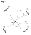
- the receiver 10 is positioned, as shown in Fig. 2 , at the intersecting point 31 of a sphere (circle) 21a having a radius equal to the distance a and being centered at the position of the GPS satellite 20a and spheres (circles) 21b to 21d of the GPS satellites 20b to 20d, formed in the same manner as the sphere 21 a.
- the calculated distances a to d include errors caused by, for example, time-lag between the GPS satellites 20a to 20d and the receiver 10, multipathing, errors in the orbit information of the GPS satellites 20a to 20d, and atmospheric fluctuation.
- the calculated spheres (circles) 22a to 22d differ from the spheres (circles) 21 a to 21 d having radii equal to the actual distances (correct distances).
- the position of the receiver 10 can be accurately calculated by, for example, a least-square method, as the position 31, which has the same distance from the spheres (circles) 22a to 22d. In this case, at least four GPS satellites 20 must be used to calculate the position of the receiver 10.
- the differences 23a to 23d between the actual distances and the calculated distances vary among the GPS satellites 20a to 20d.
- a difference between the calculated position and the actual position i.e., positioning error, occurs due to the variation in the differences 23a to 23d of the calculated distances and the actual distances.
- r n represents the actual distances from the GPS satellites 20a to 20d to the receiver 10
- clk n represents the difference between the clocks of the GPS satellites 20a to 20d and the clock of the receiver 10
- ⁇ n represents the difference between the clocks of the satellites.
- the error factors clk n Since the clocks of the GPS satellites 20a to 20d synchronize with each other, the error factors clk n have the same value for the GPS satellites 20a to 20d. In other words, the clk n represents a clock bias of the receiver 10.
- the error factors ⁇ n can be corrected using parameters of the navigation messages of the GPS satellites 20. Since the error factor ⁇ n includes components that vary with the environment and errors after correction of the error factors ⁇ n , the error factor ⁇ n varies among the GPS satellites 20a to 20d and the error factor ⁇ n cannot be corrected by calculation or actual measurements. Accordingly, the above-described positioning errors are caused by error factors ⁇ n .
- the differences between distances r' n from the receiver 10 to the GPS satellites 20a to 20d, calculated by the least-square method, and the calculated and corrected pseudo-distances pr n of the GPS satellites 20a to 20d are defined as pseudo clock biases.
- ⁇ r n pr n - r' n , where ⁇ r n represents a pseudo clock bias.
- the pseudo clock biases correspond to distances 24a to 24d from the spheres (circles) 22a to 22d having radii pr n and being centered at the positions of the GPS satellites 20a to 20d to the calculated position 31 of the receiver 10.
- clk' represents a common component, such as the difference between each clock of the GPS satellites 20a to 20d and the clock of the receiver 10.
- ⁇ ' n represents a variable component (uncorrectable component) in the errors corresponding to r' n .
- the farther ⁇ ' n is from zero the more incorrect the pseudo-distances pr n and ⁇ r n has a different value among the GPS satellites 20a to 20d. If the pseudo-distances pr n is incorrect, the calculated position of the receiver will differ from the actual position in many cases. In other words, the accuracy of the calculated position of the receiver 10 (i.e., GPS positioning accuracy) can be determined on the basis of the variation in the pseudo clock bias.
- GPS positioning it is necessary to determine the positions of the GPS satellites 20 at the transmission time of the positioning signals.
- the positions of the GPS satellites 20 at a predetermined time within a certain range is calculated using the satellite orbit parameters contained in the navigation messages sent from the GPS satellites 20.
- accurate transmission times are necessary.
- transmission time information can be acquired from the navigation messages.
- incorrect transmission time information time of week (TOW)
- TOW time of week
- the GPS satellites 20 move at a velocity of several kilometers per second. If the transmission time information (TOW) is incorrect, positioning is performed based on the position P2, which differs from the position P1 where the GPS satellite 20 is actually positioned. As a result, the position of the receiver 10 will be calculated incorrectly. According to this embodiment, the above-described pseudo clock biases are used to evaluate the GPS positioning accuracy, resulting in avoidance such circumstance and accurate positioning.
- TOW transmission time information
- the receiver 10 obtains the transmission time information (TOW) contained in the received navigation messages and determines the time range for search (search time period) and the interval of the searching steps on the basis of the time information. Subsequently, during the searching time, the receiver 10 calculates the position of each of the GPS satellites 20a to 20d at a plurality of transmission times (hereinafter referred to as "searching time") at each searching step from the satellite orbit parameters and other parameters. Then, the receiver 10 calculates the position of the receiver 10 at each transmission time on the basis of the positions of the GPS satellites 20a to 20d calculated at each transmission time and the pseudo-distance to the GPS satellites 20a to 20d.
- searching time a plurality of transmission times
- the receiver 10 calculates the pseudo clock biases ⁇ r n (TOW) for each transmission time on the basis of the position of the receiver 10 calculated at each transmission time. Then, the receiver 10 calculates a variation in the pseudo clock biases ⁇ r n (TOW) at each transmission time.
- Methods employing variance and/or maximum difference to the average can be used to determine the variation in the pseudo clock biases. For instance, if variance ⁇ ⁇ rn(TOW) 2 is used to represent the variation, the relationship between TOW and ⁇ ⁇ rn(TOW) 2 can be plotted in a graph shown in Fig. 7 , where the horizontal axis represents TOW and the longitudinal axis represents ⁇ rn(Tow) 2 .
- the solid line L e represents a change in the pseudo clock bias including an error
- the dotted line L i represents a change in ideal pseudo clock bias including no error.
- the GPS satellite 20 first approaches the position corresponding to that transmission time Tp and then moves away.
- the positioning error first decreases as the correct transmission time Tp approaches, and then increases as the time passes after the transmission time T p . In other words, the positioning error is minimized at the correct transmission time T p . Therefore, the time curve corresponding to the variance ⁇ rn(TOW) 2 of the pseudo clock biases ⁇ r n (TOW), which represents the positioning error, is convex downward, as shown in Fig. 7 , and has a minimum value at the correct transmission time T p .
- the receiver 10 can set the time Tp when the variance ⁇ rn(TOW) 2 of the pseudo clock biases ⁇ r n (TOW) is a minimum value within the time range for search as the correct transmission time and determine the results of positioning at this transmission time T p as the final results of positioning.
- the results of positioning at transmission time T p may be calculated separately after searching for Tp, or during the search for T p .
- the correct transmission time T p can be derived from the pseudo clock biases because the relative positions of the GPS satellites 20a to 20d vary every transmission time.
- the velocity vectors (the movement altitudes and the movement distances in a unit time) of the GPS satellites 20a to 20d differ.
- the relative positions of the GPS satellites 20a to 20d vary every transmission time.
- the receiver 10 can determine the transmission time t 2 when the pseudo clock biases are minimum values and can accurately calculate the position 31 of the receiver 10 on the basis of positions P a to P d of the GPS satellites 20a to 20d.
- the receiver 10 cannot determine the transmission time t 2 when the pseudo clock biases are minimum values. Therefore, the receiver 10 cannot calculate its position 31 on the basis of positions P a to P d of the GPS satellites 20a to 20d.
- a combination of satellites 20 that can determine the correct transmission time must be selected from the GPS satellites 20, which are the senders of the received signal.
- the GPS satellites 20a to 20d which are shown in Figs. 8A to 8C, must be selected from at least five satellites 20.
- the receiver 10 calculates a plurality of velocity vectors of the GPS satellites 20. Then, the receiver 10 generates at least one combination of the velocity vectors from the calculated velocity vectors and selects a plurality of satellites 20 on the basis of the generated combination of velocity vectors.
- a method of selecting the GPS satellites 20 on the basis of a combination of velocity vectors will be briefly described as an example.
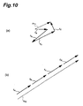
- the receiver 10 that has generated the combination of transmission vectors calculates the sum of the velocity vectors (vector sum) for each combination.
- a smaller vector sum leads to higher possibility that the relative position of the GPS satellites 20 corresponding to the velocity vectors included in the combination will vary every transmission time.
- the vector sum r T1 is relatively small, as shown in Fig. 10A .
- the vector sum r T2 is large, as shown in Fig. 10B .
- the receiver 10 selects a plurality of satellites 20 corresponding to the combination having the smallest vector sum. In this way, the receiver 10 can determine the correct transmission time leading to minimum pseudo clock biases and calculate its position at the correct transmission time. Consequently, the user of the receiver 10 can acquire a highly accurate current position.
- Fig. 11 illustrates a functional configuration of the receiver 10 shown in Fig. 1 .
- Fig. 12 illustrates a hardware configuration of the receiver 10.
- the calculated pseudo-distance pr n is a value in which ⁇ n has already corrected.
- the receiver 10 includes a signal receiving unit 11, a velocity-vector calculating unit 12, a satellite selecting unit 13, a distance calculating unit 14, a position calculating unit 15, a distance-difference calculating unit 16, a position-accuracy evaluating unit 17, a satellite-accuracy evaluating unit 18, and an output unit 19.
- the receiver 10 may also have a function of mobile communication, as described above.
- the receiver 10 includes a central processing unit (CPU) 101, a random access memory (RAM) 102, a read only memory (ROM) 103, an operating unit 104, a wireless communication unit 105, a display 106, an antenna 107, and a IC chip 108 for positioning.
- the functions of the units illustrated in Fig. 11 are provided by the operation of these hardware.
- the IC chip 108 functions as the velocity-vector calculating unit 12, the satellite selecting unit 13, the distance calculating unit 14, the position calculating unit 15, the distance-difference calculating unit 16, the position-accuracy evaluating unit 17, and the satellite-accuracy evaluating unit 18.
- the receiver 10 may not include the IC chip 108 and the functions of the units illustrated in Fig. 11 may be provided by other hardware (e.g., the CPU 101, the RAM 102, or the ROM 103).
- the signal receiving unit 11 is means for receiving signals sent from the GPS satellites 20.
- the signal receiving unit 11 outputs the information contained in the received signals to the velocity-vector calculating unit 12, the distance calculating unit 14, and the position calculating unit 15.
- the signal receiving unit 11 functions as a clock and outputs information about the reception time of the positioning signals, together with the above-mentioned information, to the distance calculating unit 14.
- the signal receiving unit 11 receives signals from a plurality of GPS satellites 20.
- the velocity-vector calculating unit 12 is velocity-vector calculating means for calculating the velocity vectors of the GPS satellites 20 on the basis of signals sent from the GPS satellites 20 and received by the signal receiving unit 11.
- the velocity-vector calculating unit 12 outputs the calculated velocity vectors of the GPS satellites 20 to the satellite selecting unit 13.
- the semimajor axis of the ellipsoidal orbit of a satellite 20, the eccentricity of the orbit, the orbital inclination, the right ascension of ascending node, and the argument of perigee are represented by a, e, i, ⁇ , and ⁇ , respectively.
- the velocity-vector calculating unit 12 acquires a velocity vector r T in the ECEF coordinate system at a time t.
- the velocity-vector calculating unit 12 stores a program that enables such a series of calculation in advance and reads out the program, if necessary to calculate the velocity vector r T of a GPS satellite 20 in the ECEF coordinate system.
- the velocity vector r T in the ECEF coordinate system may be indicated by X(x, y, z).
- the velocity-vector calculating unit 12 may calculate a velocity vector by other methods. For example, the velocity-vector calculating unit 12 may calculate a velocity vector based on the variation over time in the position of the GPS satellite 20.
- the satellite selecting unit 13 is a signal-source selecting means for generating a combination of velocity vectors from a plurality of velocity vectors calculated by the velocity-vector calculating unit 12 and selecting a combination of GPS satellites 20 from a plurality of GPS satellites, which are the senders of the signals received by the signal receiving unit 11.
- the satellite selecting unit 13 outputs satellite selecting information about the selected GPS satellites 20 to the position calculating unit 15.
- the method of selecting the GPS satellites 20 is not limited to a single method. Several methods of selecting the GPS satellites 20 are described below.
- the satellite selecting unit 13 With the first method, the satellite selecting unit 13 generates a combination C of an m number of input velocity vectors X 1 (x 1 , y 1 , z 1 ) to X m (x m , y m , Z m ). Then, the satellite selecting unit 13 calculates the vector sum of the three dimensional vectors of the generated combination C and determines whether the magnitude of the vector sum is smaller than or equal to a predetermined threshold value TH a . If the magnitude of the vector sum is smaller than or equal to the predetermined threshold value TH a , the satellite selecting unit 13 selects an m number of GPS satellites 20 corresponding to the m number of input velocity vectors as signal transmitters used for estimation of position.
- the magnitude (norm) of the vector sum v is represented by ⁇ v ⁇ . If ⁇ v ⁇ ⁇ TH a , the satellite selecting unit 13 selects an m number of GPS satellites 20.
- the method of calculating the vector sum is not limited to the method indicated by Equation (2).
- the magnitude of the vector sum v' is represented by ⁇ v' ⁇ .
- the satellite selecting unit 13 compares a predetermined threshold value TH' a with the norm ⁇ v' ⁇ . If ⁇ v' ⁇ ⁇ TH' a , the satellite selecting unit 13 selects an m number of GPS satellites 20.
- the satellite selecting unit 13 generates combinations each including a number of velocity vectors less than the number of input velocity vectors, calculates the vector sum of each combination, and selects GPS satellites 20 corresponding to the velocity vectors constituting the smallest vectors sum among the calculated vectors sums.
- the satellite selecting unit 13 selects a limited number of GPS satellites 20 used for positioning in order to more accurately calculate the position of the receiver 10.
- the method of setting the number of GPS satellites 20 is not limited.
- the number may be stored in the satellite selecting unit 13 in advance and read out if necessary, or the number of the GPS satellites 20 may be set on the basis of information input from another component.
- the satellite selecting unit 13 selects five GPS satellites 20 from six GPS satellites 20a to 20f.
- the velocity vectors X 1 to X 6 correspond to the GPS satellites 20a to 20f, respectively.
- the satellite selecting unit 13 first generates a combination including five velocity vectors. In other words, the satellite selecting unit 13 generates a combination of five GPS satellites 20 corresponding to five velocity vectors.
- C 1 X 1 ⁇ X 2 ⁇ X 3 ⁇ X 4 ⁇ X 5
- C 2 X 1 ⁇ X 2 ⁇ X 3 ⁇ X 4 ⁇ X 6
- C 3 X 1 ⁇ X 2 ⁇ X 3 ⁇ X 5 ⁇ X 6
- C 4 X 1 ⁇ X 2 ⁇ X 4 ⁇ X 5 ⁇ X 6
- C 5 X 1 ⁇ X 3 ⁇ X 4 ⁇ X 5 ⁇ X 6
- C 6 X 2 ⁇ X 3 ⁇ X 4 ⁇ X 5 ⁇ X 6
- the satellite selecting unit 13 may apply the vector sum of two-dimensional vectors to the second method.
- the number of GPS satellites 20 selected by the satellite selecting unit 13 in a single process is not limited.
- the satellite selecting unit 13 may select four GPS satellites 20 based on six velocity vectors or may select one GPS satellite 20 based on two velocity vectors.
- the satellite selecting unit 13 selects GPS satellites 20 by evaluating the variation in the directions of the velocity vectors, the variation in the magnitudes of the velocity vectors, or the variations in both the directions of the velocity vectors and the magnitudes of the velocity vectors.
- the satellite selecting unit 13 generates combination C consisted of an m number of input vectors X 1 (x 1 , y 1 , z 1 ) to X m (x m , y m z m ).
- the satellite selecting unit 13 converts the m number of input vectors X 1 (x 1 , y 1 , z 1 ) to X m (x m , y m , z m ) to vectors in a local rectangular coordinate system and acquires velocity vectors X' 1 (x' 1 , y' 1 , z' 1 ) to X' m (x' m , y' m , z' m ) in the local rectangular coordinate system.
- the satellite selecting unit 13 evaluates the variation in the calculated two-dimensional velocity directions for the generated combination C.
- the satellite selecting unit 13 evaluates the variation in the calculated two-dimensional velocity directions on the basis of, for example, sample variance or the maximum difference from the average value.
- the satellite selecting unit 13 calculates the evaluation value h using one of the methods.
- the evaluation value h represents a variation in the combination C. Subsequently, the satellite selecting unit 13 determines whether the evaluation value h is greater than or equal to a predetermined threshold value TH c . If h ⁇ TH c , the satellite selecting unit 13 selects an m number of GPS satellites 20 corresponding to the m number of velocity vectors.
- the satellite selecting unit 13 performs the same calculation when the GPS satellites 20 are selected on the basis of the variation in the magnitudes of the velocity vectors. If the evaluation value representing the variation is greater than or equal to a predetermined threshold value, an m number of GPS satellites 20 are selected. Alternatively, the satellite selecting unit 13 may select an m number of GPS satellites 20 when the sum of an evaluation value representing the variation in the directions of the velocity vectors and an evaluation value representing the variation in the magnitudes of the velocity vectors is greater than or equal to a predetermined threshold value.
- the satellite selecting unit 13 applies the third method to select a limited number of GPS satellites 20 to be used for positioning. However, the satellite selecting unit 13 selects the GPS satellites 20 on the basis of a variation in the velocity vectors, instead of a vector sum.
- the velocity vectors X 1 to X 6 correspond to the GPS satellites 20a to 20f, respectively.
- the satellite selecting unit 13 first converts the six velocity vectors X 1 (X 1 , y 1 z 1 ) to X 6 (x 6 , y 6 , z 6 ) to velocity vectors X' 1 (x' 1 , y' 1 , z' 1 ) to X' 6 (x' 6 , y' 6 , z' 6 ) in a local rectangular coordinate system. Then, the satellite selecting unit 13 calculates the two-dimensional velocity directions of each converted velocity vector by Equation (4).
- the satellite selecting unit 13 selects GPS satellites 20 that correspond to the combination having the maximum evaluation value. For example, if the evaluation value h 5 is greater than the other evaluation values, the satellite selecting unit 13 selects the GPS satellites 20a, 20c, 20d, 20e, and 20f. When a limited number of GPS satellites 20 is selected on the basis of only the variation in the magnitudes of the velocity vectors, the satellite selecting unit 13 carries out the same process.
- the satellite selecting unit 13 calculates evaluation values ha n that represent the variation in the direction of the velocity vectors and numbers the combinations C n from 1 to 6 in the order from the minimum value to the maximum value. Furthermore, the satellite selecting unit 13 calculates evaluation values hb n that represent variation in the magnitudes of the velocity vectors and numbers the combinations C n from 1 to 6 in the order from the minimum value to the maximum value. Then, the satellite selecting unit 13 calculates the sum of the numbers for each of the combinations C n and selects the GPS satellites 20 that correspond to the combination having the greatest sum.
- the satellite selecting unit 13 selects GPS satellites 20a, 20b, 20c, 20d, and 20f corresponding to the combination C 2 .
- the number of GPS satellites 20 selected by the satellite selecting unit 13 in a single process is not limited.
- the satellite selecting unit 13 may select four GPS satellites 20 based on six velocity vectors or may select nine GPS satellites 20 based on ten velocity vectors.
- a program for selecting the GPS satellites 20 (e.g. a program for performing the first method) is stored in the satellite selecting unit 13 in advance and is read out if necessary.
- the distance calculating unit 14 is means for calculating the distance between each GPS satellite 20 and the receiver 10 on the basis of information input from the signal receiving unit 11.
- the distance calculating unit 14 calculates the time difference based on the signal transmission time included in the information input from the signal receiving unit 11 and information about the reception time and calculates the pseudo-distance by multiplying the calculated time difference by the speed of light.
- the distance calculating unit 14 calculates the pseudo-distance for each GPS satellite 20 on the basis of the identification information of each GPS satellite 20. For this reason, a program for calculating the pseudo-distance is stored in the distance calculating unit 14 in advance and is read out if necessary.
- the method of calculating such distance is not limited, and may be any method including existing methods.
- the distance calculating unit 14 outputs information indicating the calculated distances to the position calculating unit 15 and the distance-difference calculating unit 16.
- the position calculating unit 15 is position calculating means for calculating the position of the receiver 10 on the basis of signals sent from GPS satellites 20 selected by the satellite selecting unit 13 and received by the signal receiving unit 11 at the time each signal is sent. More specifically, the position calculating unit 15 determines the positions of the GPS satellites 20 indicated by the satellite selecting information input from the satellite selecting unit 13 on the basis of orbit information and transmission time information of the GPS satellites 20 input from the signal receiving unit 11. Then, the position calculating unit 15 calculates the position of the receiver 10 using the determined positions of the GPS satellites 20.
- the position calculating unit 15 determines the GPS satellites 20 of which positions are to be specified on the basis of the satellite selecting information input from the satellite selecting unit 13. For example, if the information input from the signal receiving unit 11 relates to six GPS satellites 20a to 20f and the satellite selecting information input from the satellite selecting unit 13 indicates the GPS satellites 20a to 20d, the position calculating unit 15 determines to specify the positions of only the GPS satellites 20a to 20d.
- the position calculating unit 15 uses the transmission time information to determine the searching time period and the interval of the searching step. For example, the position calculating unit 15 sets the searching time period to a range of several seconds to several tens of seconds (e.g., five seconds) centered at the time indicated by the transmission time information and sets the interval of the searching step to several microseconds to several hundred microseconds (e.g., 100 ms). For this, a program for setting the searching time period and the interval of the searching step is stored in the position calculating unit 15 in advance.
- the position calculating unit 15 calculates the position of the target GPS satellite 20 on the basis of the satellite orbit parameters and other parameters at each time (searching time) in each searching step in the searching time period. Then, the position calculating unit 15 calculates the position of the receiver 10 at each searching time by, for example, a least-square method algorithm, on the basis of the positions of the GPS satellites 20 calculated at each searching time and information about the pseudo-distances input from the distance calculating unit 14. The position calculating unit 15 calculates information indicating the positions of the GPS satellites 20 and the receiver 10 as coordinates representing the longitudes and latitudes (and altitude, for the GPS satellites 20). The position calculating unit 15 outputs the information indicating the positions of the receiver 10 and the GPS satellites 20 calculated at each searching time to the distance-difference calculating unit 16.
- the distance-difference calculating unit 16 is means for calculating the distances r' n between the receiver 10 and the GPS satellites 20 on the basis of the positions of the receiver 10 and the GPS satellites 20 input from the position calculating unit 15 and calculating the differences ⁇ r n between the distances r' n and the pseudo-distances pr n input from the distance calculating unit 14 for each GPS satellite 20. Since the positions of the receiver 10 and the GPS satellites 20 calculated at each searching time are input from the position calculating unit 15, the distance-difference calculating unit 16 calculates pseudo clock biases ⁇ r n (TOW) at each searching time. The distance-difference calculating unit 16 outputs the calculated pseudo clock biases ⁇ r n (TOW) to the position-accuracy evaluating unit 17.
- the position-accuracy evaluating unit 17 is transmission-time setting means for evaluating the accuracy of the positions of the receiver 10 calculated by the position calculating unit 15 and setting one of the times corresponding to the positions as the transmission time.
- the position-accuracy evaluating unit 17 is also estimated-position setting means for setting the position of the receiver 10 corresponding to the set transmission time as an estimated position of the receiver 10.
- the position-accuracy evaluating unit 17 calculates the variation in the pseudo clock biases ⁇ r n (TOW) for the GPS satellites 20a to 20d input from the distance-difference calculating unit 16 at each searching time and evaluates the accuracy of the position of the receiver 10 calculated by the position calculating unit 15 on the basis of the calculated variation.
- the position-accuracy evaluating unit 17 uses variances ⁇ rn(TOW) 2 of the pseudo clock biases ⁇ r n (TOW) as values representing the variation.
- the position-accuracy evaluating unit 17 sets the time when the variances ⁇ rn(TOW) 2 of the pseudo clock biases ⁇ r n (TOW) is the smallest value during the searching time period as the correct transmission time Tp.
- the position-accuracy evaluating unit 17 determines the positioning result at the correct transmission time Tp as the final result.
- the position-accuracy evaluating unit 17 sets the position of the receiver 10 corresponding to the correct transmission time Tp as the estimated position of the receiver 10.
- the position of the receiver 10 corresponding to the correct transmission time Tp is the positioning result calculated on the basis of the correct transmission time T p by the position calculating unit 15.
- the pseudo clock biases corresponding to the transmission time Tp are represented by ⁇ r n (Tp), and the variances of the pseudo clock biases corresponding to the transmission time T p is represented by ⁇ r,(T p ) 2
- the position-accuracy evaluating unit 17 evaluates the accuracy of the position of the receiver 10 on the basis of the variances ⁇ ⁇ rn(Tp ) 2 .
- a program for evaluation is stored in the position-accuracy evaluating unit 17 and read out if necessary.
- the position-accuracy evaluating unit 17 evaluates that the accuracy of the calculated position of the receiver 10 is low when the variances ⁇ rn(T p ) 2 are greater than a predetermined threshold value and evaluates that the accuracy of the calculated position of the receiver 10 is high when the variances ⁇ rn(T p ) 2 are smaller than the predetermined threshold value. Furthermore, the position-accuracy evaluating unit 17 may use the variances ⁇ rn(T p ) 2 as values indicating the accuracy of the calculated position of the receiver 10 (i.e., values indicating the level of deviation of the calculated position from the actual position of the receiver 10).
- the position-accuracy evaluating unit 17 may be configured such that the level of deviation of the calculated position from the actual position of the receiver 10 is estimated by multiplying a factor tuned in advance by the variances ⁇ rn(T p ) 2 . the variances ⁇ rn(T p ) 2 ⁇
- the position-accuracy evaluating unit 17 outputs the variances ⁇ rn(T p) 2 and the positioning result (the estimated position of the receiver 10 set as the positioning result) at the correct transmission time Tp to the satellite-accuracy evaluating unit 18. Separately, information about the evaluation performed by the position-accuracy evaluating unit 17 is used appropriately at the receiver 10.
- the position-accuracy evaluating unit 17 evaluates the accuracy as being high (if a result indicating a level of accuracy higher than a predetermined level is acquired), the position-accuracy evaluating unit 17 outputs the positioning result (information about the position of the receiver 10 calculated by the position calculating unit 15) to the output unit 19. At this time, the position-accuracy evaluating unit 17 may output information about the evaluation by the position-accuracy evaluating unit 17, together with the positioning result, to the output unit 19.
- the position-accuracy evaluating unit 17 evaluates the accuracy as being low (if a result indicating a level of accuracy higher than a predetermined level is not acquired), the position-accuracy evaluating unit 17 outputs information about a number of GPS satellites 20 to be selected to the satellite selecting unit 13, in order to perform positioning again by limiting the number of GPS satellites 20 of which positions are specified by the position calculating unit 15.
- the position-accuracy evaluating unit 17 may finish the positioning process when it evaluates the accuracy as being low.
- the satellite-accuracy evaluating unit 18 is means for evaluating the accuracy GPS satellites 20 used to calculate the position of the receiver 10 by the position calculating unit 15 on the basis of the variation between the pseudo clock biases ⁇ rn(Tp) of the GPS satellites 20 input from the position-accuracy evaluating unit 17.
- the accuracy of the GPS satellites 20 is equivalent to the ability of calculating pseudo-distances pr n having small error variation components ⁇ ' using signals from the GPS satellites 20 by the distance calculating unit 14.
- the evaluation by the satellite-accuracy evaluating unit 18 is based on the fact that, when the error variation components ⁇ ' is small, the variation in the pseudo clock biases ⁇ r n (Tp) between the GPS satellites 20 is small, and when the error variation components ⁇ ' is large, the variation is large.
- the position-accuracy evaluating unit 17 performs clustering of the GPS satellites 20 based on the pseudo clock biases ⁇ r n (T p ). Through the clustering, GPS satellites having pseudo clock biases ⁇ r n (T p ) that differ greatly from that of other GPS satellites can be extracted.
- satellite-accuracy evaluating unit 18 evaluates the accuracy of the GPS satellites 20 extracted on the basis of the pseudo clock biases ⁇ r n (T p ) as being low.
- a program for evaluating the accuracy of the GPS satellites 20 is stored in the satellite-accuracy evaluating unit 18 and is read out if necessary to perform evaluation.
- Information about the evaluation of the accuracy of the GPS satellites 20 by the satellite-accuracy evaluating unit 18 is used appropriately at the receiver 10. For example, if the number of GPS satellites 20 that have been evaluated to have low accuracy is less than a predetermined number, the satellite-accuracy evaluating unit 18 outputs the positioning result (information about the position of the receiver 10 calculated by the position calculating unit 15) to the output unit 19. The satellite-accuracy evaluating unit 18 may output information about the evaluation on the GPS satellites 20, together with the positioning result, to the output unit 19.
- the satellite-accuracy evaluating unit 18 outputs information about a number of GPS satellites 20 to be selected in order to perform positioning again by limiting the number of GPS satellites 20 of which positions are specified by the position calculating unit 15 to the satellite selecting unit 13.
- the satellite-accuracy evaluating unit 18 may finish the positioning process when the number of GPS satellites 20 that have been determined to have low accuracy is more than a predetermined number.
- the output unit 19 is means for outputting information input from the position-accuracy evaluating unit 17 and the satellite-accuracy evaluating unit 18 as a screen display and/or sound.
- the output information includes, for example, information about the position of the receiver 10 calculated by the position calculating unit 15.
- the user of the receiver 10 can recognize the position of the receiver 10, i.e., the position of himself or herself, by referring to the output information.
- Fig. 13 is a flow chart illustrating the process carried out by the receiver 10.
- the positioning process carried out by the receiver 10 started with, for example, the user input on a positioning request to the receiver 10 via the operating unit 104.
- the positioning process may start with another method such as another application program, which is run in the receiver 10, outputting a positioning request.
- the signal receiving unit 11 receives positioning signals sent from the GPS satellites 20 (Step S01).
- the signal receiving unit 11 outputs the information contained in the received signals to the velocity-vector calculating unit 12 and the distance calculating unit 14.
- the distance calculating unit 14 calculates the distances (pseudo-distances) between the GPS satellites 20 and the receiver 10 on the basis of the information input from the signal receiving unit 11 (Step S02).
- the distance calculating unit 14 outputs information about the pseudo-distances to the position calculating unit 15 and the distance-difference calculating unit 16.
- the velocity-vector calculating unit 12 calculates the velocity vectors of the GPS satellites 20 on the basis of the information input from the signal receiving unit 11 (Step S03, velocity-vector calculating step).
- the velocity-vector calculating unit 12 uses the above-described method to calculate velocity vectors in an ECEF coordinate system for each of the GPS satellites 20 and output the calculation results to the satellite selecting unit 13.
- the calculation of the velocity vectors by the velocity-vector calculating unit 12 and the calculation of the pseudo-distances by the distance calculating unit 14 may be carried out simultaneously.
- the satellite selecting unit 13 generates a combination of velocity vectors from a plurality of velocity vectors calculated and selects a combination of GPS satellites 20 from a plurality of GPS satellites, which are the senders of the signals received by the signal receiving unit 11, based on the generated combination of velocity vectors (Step S04, signal-source selecting step).
- the satellite selecting unit 13 outputs satellite selecting information about the selected GPS satellites 20 to the position calculating unit 15.
- the satellite selecting unit 13 may use any suitable method based on the content of the positioning request. For example, to determine whether or not all of the m number of GPS satellites 20 corresponding to an m number of input velocity vectors are to be selected, the satellite selecting unit 13 may use the above-described first or third method. To select an n number (where m>n) of GPS satellites 20 among the m number of GPS satellites 20 corresponding to the m number of input velocity vectors, the satellite selecting unit 13 may use the above-described second or fourth method.
- the position calculating unit 15 extracts the GPS satellites 20 of which the positions are to be determined from the GPS satellites 20 corresponding to the signals received by the signal receiving unit 11 on the basis of the input satellite selecting information. Then, the position calculating unit 15 calculates the position of the signal receiving unit 11 from information about the positions of the extracted GPS satellites 20 and information about the pseudo-distances input from the distance calculating unit 14 (Step S05, position calculating step). The position calculating unit 15 outputs information about the calculated position of the receiver 10 to the distance-difference calculating unit 16.
- the distance-difference calculating unit 16 calculates the pseudo clock biases ⁇ r n (TOW), which is the difference between the distances from the input position of the receiver 10 to the GPS satellites 20 and the pseudo-distances from the distance calculating unit 14, for every GPS satellite 20, which are input from the position calculating unit 15 (Step S06).
- the distance-difference calculating unit 16 outputs the calculated pseudo clock biases ⁇ r n (TOW) to the position-accuracy evaluating unit 17 and the satellite-accuracy evaluating unit 18.
- the position-accuracy evaluating unit 17 and the satellite-accuracy evaluating unit 18 evaluate the positioning accuracy (Step S07).
- the position-accuracy evaluating unit 17 evaluates the accuracy of the position of the receiver 10 calculated by the position calculating unit 15 on the basis of the variation in the pseudo clock biases ⁇ r n (TOW) between the GPS satellites 20.
- the position-accuracy evaluating unit 17 sets the time when the variances ⁇ rn(TOW) 2 of the pseudo clock biases is the smallest value as a correct transmission time Tp (transmission-time setting step).
- the position-accuracy evaluating unit 17 sets the positioning result at the transmission time T p , which is set as the correct transmission time, as the final result (i.e., estimated position of the receiver 10) (estimated-position setting step).
- the satellite-accuracy evaluating unit 18 evaluates the accuracy of the GPS satellites 20 used to calculate the position of the receiver 10 by the position calculating unit 15 on the basis of the variation in the pseudo clock biases ⁇ r n (TOW) of the GPS satellites 20.
- the position-accuracy evaluating unit 17 and the satellite-accuracy evaluating unit 18 determine that a positioning result having a predetermined accuracy is acquired on the basis of the evaluation (YES in Step S08)
- the position-accuracy evaluating unit 17 outputs the positioning result (i.e., information about the position of the receiver 10 calculated by the position calculating unit 15) to the output unit 19, and the output unit 19 outputs the positioning result (Step S09). In this way, the user of the receiver 10 can acquire the positioning result.
- Step S08 the position-accuracy evaluating unit 17 and the satellite-accuracy evaluating unit 18 determine to carry out positioning again and outputs information about a number of GPS satellites 20 to be selected to the satellite selecting unit 13. In this way, Steps S04 to S08 are repeated. For example, if the accuracy of the position of the receiver 10 calculated on the basis of six GPS satellites 20 does not achieve a predetermined level, the position-accuracy evaluating unit 17 and the satellite-accuracy evaluating unit 18 output information for reducing the six GPS satellites 20 to five GPS satellites 20 to the satellite selecting unit 13. In such a case, the satellite selecting unit 13 selects five GPS satellites 20 in such a manner as the second or fourth method described above.
- positioning may be finished at a predetermined timing.
- a predetermined threshold value for example, less than or equal to four
- the position-accuracy evaluating unit 17 and the satellite-accuracy evaluating unit 18 may determine that positioning with a predetermined accuracy cannot be carried out even if a limited number of GPS satellites 20 is selected and may end the process.
- the satellite selecting unit 13 can change the method of selecting the GPS satellites 20, each time. For example, the satellite selecting unit 13 may use the above-described first method for the first process and then may use the above-described second method for the second process (i.e., repetition of the first process).
- a positioning program 81 is stored in a program-storing area 80a in a recording medium 80 included in a computer.
- the positioning program 81 includes a main module 81a that controls the overall positioning process, a signal receiving module 81b, a velocity-vector calculating module 81c, a satellite selecting module 81d, a distance calculating module 81e, a position calculating module 81 f, a distance-difference calculating module 81 g, a position-accuracy evaluating module 81h, a satellite-accuracy evaluating module 81i, and an output module 81j.
- the signal receiving module 81b, the velocity-vector calculating module 81 c, the satellite selecting module 81 d, the distance calculating module 81 e, the position calculating module 81f, the distance-difference calculating module 81g, the position-accuracy evaluating module 81h, the satellite-accuracy evaluating module 81i, and the output module 81j have the same functions as the signal receiving unit 11, the velocity-vector calculating unit 12, the satellite selecting unit 13, the distance calculating unit 14, the position calculating unit 15, the distance-difference calculating unit 16, the position-accuracy evaluating unit 17, the satellite-accuracy evaluating unit 18, and the output unit 19, respectively, in the receiver 10.
- All or part of the positioning program 81 may be transmitted through a transmission medium, such as a communication line, and may be received by and recorded (installed) in other devices.
- a transmission medium such as a communication line
- a transmission time of signals from the GPS satellites 20 can be accurately estimated by selecting the GPS satellites 20 on the basis of a combination of velocity vectors, and setting one time selected from a plurality of times as the transmission time on the basis of signals from the selected GPS satellites 20.
- the position of the receiver 10 can be accurately estimated by setting the position of the receiver 10 corresponding to the time set as transmission time, as the estimated position of the receiver 10.
- a plurality of GPS satellites 20 may be selected on the basis of a vector sum corresponding to a combination of velocity vectors. Since the vector sum can be easily calculated, the transmission time can be easily estimated by employing this method.
- the estimation accuracy of the transmission time can be maintained at a certain level since the vector sum is evaluated using a threshold value.
- the second method a combination of GPS satellites 20 that allows the transmission time to be estimated with the highest accuracy can be acquired since GPS satellites 20 that correspond to a combination having the minimum velocity sum are selected.
- a plurality of GPS satellites 20 can be selected on the basis of a value indicating the variation in velocity vectors included in a combination of velocity vectors. Using this value, the variation in the relative positions of the GPS satellites 20 can be accurately derived, and, as a result, the transmission time can be accurately estimated.
- the estimation accuracy of the transmission time can be maintained at a certain level since the value indicating the variation in velocity vectors is evaluated using a threshold value.
- the fourth method a combination of GPS satellites 20 that allows the transmission time to be estimated with the highest accuracy can be acquired since GPS satellites 20 that correspond to a combination having the maximum value indicating the variation in velocity vectors are selected.
- the satellite selecting unit 13 selects GPS satellites 20 on the basis of velocity vectors.
- the method of selecting the GPS satellites 20 is not limited.
- the satellite selecting unit 13 may employ both a known method and a method using velocity vectors to select the GPS satellites 20.
- Examples of known methods include a method of evaluating the reception of the GPS satellite by a C/N ratio (signal-to-noise ratio) of a signal, a method of evaluating the variation in pseudo-distances on the basis of the root mean square (RMS) of the pseudo-distances, and a method of evaluating the geometric position of a GPS satellite using dilution of precision (DOP).
- C/N ratio signal-to-noise ratio
- RMS root mean square
- DOP dilution of precision
- the satellite selecting unit 13 may first extract GPS satellites 20 of which the C/N ratio, RMS, and DOP are greater than predetermined threshold values and may select specific GPS satellites 20 from the extracted GPS satellites 20 using a method according to the above-described embodiments, i.e., a method based on velocity vectors.
- the positioning accuracy is evaluated using pseudo clock biases.
- the positioning accuracy may be evaluated using another method, such as receiver autonomous integrity monitoring (RAIM). Details of RAIM is described in, for example, BW Parkinson, JJ Spilker, "Global Positioning System: Theory and Applications Volume II - Chapter 5", American Institute of Aeronautics and Astronautics, Inc., pp. 143-164, 1996 .
- RAIM receiver autonomous integrity monitoring
- the GPS satellites 20 are used as signal transmitters.
- pseudo-satellites or base stations forming a mobile communication network may be used as signal transmitters.
- the main component used for positioning is the receiver 10, which is also the subject of positioning.
- the main component used for positioning and the subject of positioning may be different.
- the main component used for positioning may be a positioning server provided separately from the receiver 10.
- the positioning server for example, is connected to the receiver 10 via the mobile communication network, receives information required for positioning from the receiver 10, and carries out positioning.
- the positioning server may receive information required for positioning from the receiver 10 and may carry out all of the calculations associated with positioning.
- the positioning server may receive information about the distances between the GPS satellites 20 and the receiver 10, which are calculated by the receiver 10, and may carry out calculations associated with positioning on the basis of the information about the distances.
- the positioning system described in claims may be applied for various devices, such as receivers and servers.
Description
- The present invention relates to a positioning system, an IC chip for positioning, a positioning method, and a positioning program for estimating the position of a receiver.
- Positioning of receivers using a global positioning system (GPS) or Galileo is known technology. Such systems perform positioning on the basis of the distance from a satellite (which may also be a pseudo-satellite), which is a positioning signal transmitter, to a receiver. Another positioning method referred to as a hybrid method is also known which uses signals from a satellite and signals from a mobile communication network at the same time.
- With these positioning methods, the distance from a satellite to a receiver is calculated on the basis of the transmission time and the time of receipt of a positioning signal sent from the satellite to the receiver, and calculation for the positioning is performed using the calculated distance. If the distances from a plurality of satellites to a receiver and the positions of the satellites are accurately calculated, the position of the receiver can be determined through calculation of the intersection of spheres having radii from the centers at which the satellites lie, the radii corresponding to the distances from the positions of the satellites. However, such a method to calculate the distance involves various factors that may cause errors, which preclude accurate calculation of the distance. Therefore, a least-square method is used to calculate the position of the receiver on the basis of the calculated distances from the plurality of satellites to the receiver. Such a method is described in, for example, Takeyasu Sakai, "GPS Gijutsu Nyumon (Introduction to GPS Technology) (pp. 36-41)", Tokyo Denki Daigaku Shuppan, Feb. 28, 2003.
- To calculate the positions of the GPS satellites, it is necessary to acquire accurate satellite orbit information and transmission times. Usually, the satellite orbit information and the transmission time data can be acquired by receiving navigation messages that are constantly sent from the satellites. However, sometimes the transmission time cannot be correctly received. If the GPS signal intensity is low at a location, for example, at an interior, the detected transmission time information may include an error. In such a case, the position of a satellite cannot be correctly calculated due to the error in the detected transmission time information. Therefore, the sphere centered at the position of the satellite cannot be correctly calculated. As a result, the correct position of a receiver cannot be calculated.
- In this way, with a positioning method using satellites, the estimated transmission time of signals have much effect on the positioning accuracy. The accuracy of the estimated transmission time greatly varies depending on selection of the satellites to be used for positioning. In particular, if the number of satellites capable of receiving is small, or in case of the hybrid positioning, sometimes the transmission times cannot be estimated depending on the satellites to be used.
- Patent Application Laid-Open
US 2003/0162552 A1 cites a method for position estimation of an electronic device by receiving a code modulated signal transmitted by satellites. Delta range measurements which correspond to velocity measurements of the positioning receiver to the at least four satellites are taken. The delta range measurement results and the velocity measurement results are used for generating reference data for determining a local time data frequency error and the position by searching for a minimum of the reference data. - The present invention has been conceived in light of the above-described problems. It is an object of the present invention to provide a positioning system, a positioning IC chip, a positioning method, and a positioning program that are capable of accurately estimating transmission times of signals from signal transmitters and to accurately estimate the position of a receiver on the basis of the estimated transmission times.
- To achieved the above-described purpose, the present invention provides a positioning system estimating the position of a receiver, the positioning system including velocity-vector calculating means for calculating velocity vectors of a plurality of signal transmitters on the basis of signals sent from the signal transmitters to the receiver; signal-transmitter selecting means for generating a combination of velocity vectors from the velocity vectors calculated by the velocity-vector calculating means and selecting a combination of signal transmitters from the plurality of signal transmitters on the basis of the selected combination of velocity vectors; position calculating means for calculating positions of the receiver at a plurality of times, the times being signal transmission times, on the basis of signals transmitted from the signal transmitters selected by the signal-transmitter selecting means and received by the receiver; transmission-time setting means for evaluating the accuracy of the positions of the receiver calculated by the position calculating means and setting one time selected from the plurality of times corresponding to the plurality of positions as a transmission time; and estimated-position setting means for setting the position of the receiver corresponding to the transmission time set by the transmission-time setting means as an estimated position of the receiver.
- The present invention provides a positioning IC chip estimating the position of a receiver, the positioning IC chip including velocity-vector calculating means for calculating velocity vectors of a plurality of signal transmitters on the basis of signals sent from the signal transmitters to the receiver; signal-transmitter selecting means for generating a combination of velocity vectors from the velocity vectors calculated by the velocity-vector calculating means and selecting a combination of signal transmitters from the plurality of signal transmitters on the basis of the generated combination of velocity vectors; position calculating means for calculating positions of the receiver at a plurality of times, the times being signal transmission times, on the basis of signals transmitted from the signal transmitters selected by the signal-transmitter selecting means and received by the receiver; transmission-time setting means for evaluating the accuracy of the positions of the receiver calculated by the position calculating means and setting one time selected from the plurality of times corresponding to the plurality of positions as a transmission time; and estimated-position setting means for setting the position of the receiver corresponding to the transmission time set by the transmission-time setting means as an estimated position of the receiver.
- The present invention provides a positioning method in which a positioning system estimates the position of a receiver, the positioning method including a velocity-vector calculating step in which the positioning system calculates velocity vectors of a plurality of signal transmitters on the basis of signals sent from the signal transmitters to the receiver; a signal-transmitter selecting step in which the positioning system generates a combination of velocity vectors from the velocity vectors calculated in the velocity-vector calculating step and selects signal transmitters from the plurality of signal transmitters on the basis of the generated combination of velocity vectors; a position calculating step in which the positioning system calculates positions of the receiver at a plurality of times, the times being signal transmission times, on the basis of signals transmitted from the signal transmitters selected in the signal-transmitter selecting step and received by the receiver; a transmission-time setting step in which the positioning system evaluates the accuracy of the positions of the receiver calculated in the position calculating step and sets one time selected from the plurality of times corresponding to the plurality of positions as a transmission time; and a estimated-position setting step in which the positioning system sets the position of the receiver corresponding to the transmission time set in the transmission-time setting step as an estimated position of the receiver.
- The present invention provides a positioning program for causing a computer to estimate the position of a receiver, the program causing the computer to execute: a velocity-vector calculating function of calculating velocity vectors of a plurality of signal transmitters on the basis of signals sent from the signal transmitters and received by the receiver; a signal-transmitter selecting function of generating a combination of velocity vectors from the velocity vectors calculated by the velocity-vector calculating function and of selecting signal transmitters from the plurality of signal transmitters on the basis of the generated combination of velocity vectors; a position calculating function of calculating positions of the receiver at a plurality of times, the times being signal transmission times, on the basis of signals transmitted from the signal transmitters selected by the signal-transmitter selecting function and received by the receiver; a transmission-time setting function of evaluating the accuracy of the positions of the receiver calculated by the position calculating function and of setting one time selected from the plurality of times corresponding to the plurality of positions as a transmission time; and a estimated-position setting function of setting the position of the receiver corresponding to the transmission time set by the transmission-time setting function as an estimated position of the receiver.
- According to such a positioning system, positioning IC chip, positioning method, and positioning program, first, velocity vectors of signal transmitters are calculated on the basis of a plurality of signals sent from a plurality of signal transmitters and received by a receiver. Then, signal transmitters are selected from the plurality of signal transmitters on the basis of a combination of velocity vectors generated on the basis of the calculated velocity vectors. Then, positions of the receiver at a plurality of transmission times are calculated on the basis of signals from the selected signal transmitters. Then, the plurality of positions are evaluated to set one time from a plurality of times corresponding to the plurality of positions as a transmission time. Then, the position of the receiver corresponding to the set transmission time is set as an estimated position.
- As a result of extensive research carried out by the present inventors, it was discovered that estimation of the transmission times of the plurality of signals sent from the plurality of signal transmitters is affected by a variation over time in the relative positions of the signal transmitters. The variation over time in the relative positions of the signal transmitters can be determined from velocity vectors indicating the traveling direction and the magnitude of the velocity (speed). Therefore, by selecting a signal transmitter on the basis of the combination of velocity vectors and setting one time from a plurality of times as a transmission time on the basis of signals from the selected signal transmitter, the transmission time of the signal from the signal transmitter can be accurately estimated. Furthermore, the position of the receiver corresponding to the time set as the transmission time is set as an estimated position of the receiver, whereby the position of the receiver can be accurately estimated.
- With the positioning system according to the present invention, the signal-transmitter selecting means calculates a vector sum of the combination of velocity vectors and selects signal transmitters from the plurality of signal transmitters on the basis of the calculated vector sum.
- In such a case, the vector sum corresponding to the combination of velocity vectors is calculated, and a plurality of signal transmitters is selected according to the vector sum. In this way, the estimation of the transmission time can be easily performed by using a vector sum which can be easily calculated.
- With the positioning system according to the present invention, it is preferable that the signal-transmitter selecting means generate a combination of velocity vectors calculated by the velocity-vector calculating means and selects signal transmitters corresponding to the velocity vectors when the vector sum of the generated combination of the velocity vectors is less than or equal to a predetermined threshold value.
- In such a case, a combination of velocity vectors corresponding to the signal transmitters, which are the senders of signals, is generated, and a vector sum corresponding to the generated combination is calculated. If the magnitude of the calculated vector sum is less than or equal to a predetermined threshold value, all of the signal transmitters, which are the senders of signals, are selected. In general, the variation in the relative positions of the signal transmitters is large if the magnitude of the vector sum is small, thus enabling accurate estimation of the transmission time. Therefore, the accuracy of the estimation of the transmission time can be maintained at a certain level by evaluating the magnitude of the vector sum using a threshold value.
- With the positioning system according to the present invention, it is preferable that the signal-transmitter selecting means generate a plurality of combinations of velocity vectors each including a number of velocity vectors smaller than the number of velocity vectors calculated by the velocity-vector calculating means, calculate a vector sum of each of the generated combinations, and select signal transmitters corresponding to the velocity vectors constituting the smallest vector sum among the calculated vector sums.
- In such a case, a plurality of combinations of velocity vectors each including a number of velocity vectors smaller than the number of signal transmitters, which are the senders of signals, are generated, and a vector sum is calculated from each selected combination. Then, the signal transmitters corresponding to the velocity vectors of the smallest vector sum among the calculated vector sums are selected. In general, the variation in the relative positions of the signal transmitters is large if the magnitude of the vector sum is small, thus enabling accurate estimation of the transmission time. Therefore, the combination of the signal transmitters having the highst accuracy of the estimation of the transmission time can be obtained by selecting the signal transmitters corresponding to the combination of the smallest vector.
- With the positioning system according to the present invention, it is preferable that the signal-transmitter selecting means calculate a value indicating a variation in the velocity vectors of the combinations and select signal transmitters from the plurality of signal transmitters on the basis of the calculated value.
- In such a case, a value indicating a variation in the velocity vectors of the combinations of velocity vectors is calculated, and a plurality of signal transmitters is selected on the basis of the value. In this way, by using a value that indicates the variation, the variation in the relative positions of the signal transmitters can be accurately derived, resulting in accurate estimation of the transmission time.
- With the positioning system according to the present invention, it is preferable that the signal-transmitter selecting means generate a combination of the velocity vectors calculated by the velocity-vector calculating means and select signal transmitters corresponding to the velocity vectors when the value indicating a variation in the velocity vectors of the generated combinations is equal to or more than a predetermined threshold value.
- In such a case, a combination of velocity vectors corresponding to signal transmitters, which are the senders of signals, is generated, and a value indicating the variation in the velocity vectors of the generated combination is calculated. If the calculated value is equal to or more than a predetermined threshold value, all of the signal transmitters, which are the senders of signals, are selected. The variation in the relative positions of the signal transmitters is large if the value indicating the variation in the velocity vectors is large, thus enabling accurate estimation of the transmission time. Therefore, the accuracy of the estimation of the transmission time can be maintained at a certain level by evaluating the value indicating the variation in velocity vectors using a threshold value.
- With the positioning system according to the present invention, it is preferable that the signal-transmitter selecting means generate a plurality of combinations of velocity vectors each including a number of velocity vectors smaller than the number of velocity vectors calculated by the velocity-vector calculating means, calculate values indicating variations in the velocity vectors of each of the generated combinations, and select signal transmitters corresponding to the velocity vectors having the maximum value among the calculated values.
- In such a case, a plurality of combinations of velocity vectors each including a number of velocity vectors smaller than the number of signal transmitters, which are the senders of signals, is generated, and a value indicating a variation in the velocity vectors of each of the generated combination is calculated. Then, the signal transmitters corresponding to the velocity vectors that derive the largest value of all calculated values are selected. The variation in the relative positions of the signal transmitters is large if the value indicating the variation in the velocity vectors is large, thus enabling accurate estimation of the transmission time. Therefore, a combination of signal transmitters having the highest accuracy of estimating the transmission time can be obtained by selecting signal transmitters that correspond to the combination having the greatest value indicating the variation of velocity vectors.
- According to such a positioning system, a positioning IC chip, a positioning method, and a positioning program, since one time is set as a transmission time of signals by selecting signal transmitters on the basis of a combination of velocity vectors, calculating the position of a receiver at a plurality of times on the basis of the signals from the selected signal transmitters, and evaluating the calculated position, the transmission time of a signal from a signal transmitter can be accurately estimated, and the position of the receiver can be accurately measured by the estimation.
-
-
Fig. 1 illustrates a receiver and GPS satellites according to an embodiment of the present invention; -
Fig. 2 illustrates the principle of positioning according to an embodiment; -
Fig. 3 illustrates the principle of positioning according to an embodiment; -
Fig. 4 illustrates the principle of positioning according to an embodiment; -
Fig. 5 illustrates the positions of a GPS satellite at different times; -
Fig. 6 illustrates the concept of a pseudo clock bias; -
Fig. 7 is a graph illustrating the relationship between a TOW and the variance of a pseudo clock bias; - Figs. 8A to 8C illustrate examples in which the relative positions of the GPS satellites change;
- Figs. 9A to 9C illustrate examples in which the relative positions of the GPS satellites do not change;
-
Figs. 10A and 10B illustrates the concept of sum of velocity vectors,Fig. 10A corresponding to Figs. 8A to 8C, whileFig. 10B corresponding to Figs. 9A to 9C; -
Fig. 11 illustrates a functional configuration of the receiver shown inFig. 1 ; -
Fig. 12 illustrates a hardware configuration of the receiver shown inFig. 1 ; -
Fig. 13 is a flow chart illustrating a process (positioning method) carried out by the receiver shown inFig. 1 ; and -
Fig. 14 illustrates a configuration of a positioning program according to an embodiment. - Embodiments of the present invention will be described in detail with reference to the attached drawings. Same or equivalent components mentioned in the description will be represented by the same reference numerals, and the same descriptions will not be repeated.
- First, a
receiver 10, which is a positioning system of this embodiment, and a plurality ofGPS satellites 20, which are signal transmitters, will be described with reference toFig. 1. Fig. 1 illustrates a receiver and GPS satellites according to an embodiment of the present invention. In Fig. l, fourGPS satellites 20a to 20d are shown. However, the number ofGPS satellites 20 is not limited. - The
receiver 10 is a positioning device that receives positioning signals (measurements), which are radio waves sent from theGPS satellites 20 and estimates its own position using the positioning signals. In addition to the positioning, thereceiver 10 may perform mobile communication. Thereceiver 10 is, for example, a mobile communication terminal, such as a mobile phone. Thereceiver 10 determines its own position when, for example, a user instructs thereceiver 10 to perform positioning. - The
GPS satellites 20 are located at predetermined positions depending on time and transmit positioning signals from those positions. Four or five of theGPS satellites 20 are on each one of the six orbits at an altitude of approximately 20,000 km and move along the orbit over time. Each positioning signal sent from each of theGPS satellites 20 contains identification information for identifying the correspondingsatellite 20, information indicating the orbit of theGPS satellite 20, and information about the time the signal is sent. - The principle of positioning in this embodiment is briefly described with reference to
Figs. 2 to 4 . Here, an exemplary case in which thereceiver 10 receives positioning signals from fourGPS satellites 20a to 20d will be described. Thereceiver 10 calculates the distances to theGPS satellites 20a to 20d based on the positioning signals from theGPS satellites 20a to 20d. More specifically, thereceiver 10 calculates distances a to d from thereceiver 10 to theGPS satellites 20a to 20d, respectively, by multiplying the transmission time of a positioning signal (i.e., the elapsed time from the transmission of a positioning signal from one of theGPS satellites 20a to 20d to the reception of the positioning signal by the receiver 10) by the speed of light. The distances a to d can be derived from the flowing equations:


GPS satellites 20a to 20d, and tra to trd represent reception times of the positioning signals at thereceiver 10. - By accurate calculation of the distances between the
GPS satellites 20a to 20d and thereceiver 10, thereceiver 10 is positioned, as shown inFig. 2 , at theintersecting point 31 of a sphere (circle) 21a having a radius equal to the distance a and being centered at the position of theGPS satellite 20a and spheres (circles) 21b to 21d of theGPS satellites 20b to 20d, formed in the same manner as thesphere 21 a. - However, usually, the calculated distances a to d include errors caused by, for example, time-lag between the
GPS satellites 20a to 20d and thereceiver 10, multipathing, errors in the orbit information of theGPS satellites 20a to 20d, and atmospheric fluctuation. As shown inFig. 3 , therefore, the calculated spheres (circles) 22a to 22d differ from the spheres (circles) 21 a to 21 d having radii equal to the actual distances (correct distances). Ifdifferences 23a to 23d between the actual distances and the calculated distance are equal for theGPS satellites 20a to 20d, the position of thereceiver 10 can be accurately calculated by, for example, a least-square method, as theposition 31, which has the same distance from the spheres (circles) 22a to 22d. In this case, at least fourGPS satellites 20 must be used to calculate the position of thereceiver 10. - However, as shown in
Fig. 4 , thedifferences 23a to 23d between the actual distances and the calculated distances vary among theGPS satellites 20a to 20d. In such a case, theposition 31, which is calculated by the least-square method and is the same distance from the spheres (circles) 22a to 22d, differs from anactual position 32 of thereceiver 10. - In this case, a difference between the calculated position and the actual position, i.e., positioning error, occurs due to the variation in the
differences 23a to 23d of the calculated distances and the actual distances. - The distances (pseudo-distances) prn (n=1 to 4) between the
GPS satellites 20a to 20d and thereceiver 10 can be represented as follows:
- Here, rn represents the actual distances from the
GPS satellites 20a to 20d to thereceiver 10; clkn represents the difference between the clocks of theGPS satellites 20a to 20d and the clock of thereceiver 10; and βn represents the difference between the clocks of the satellites. These error factors rn, clkn, and βn, which results from, for example, errors in the orbit information and an atmospheric fluctuation, can be corrected. In contrast, εn represents errors in the distance, which results from multipathing and errors that remain after correction of βn, a nd cannot be corrected. - Since the clocks of the
GPS satellites 20a to 20d synchronize with each other, the error factors clkn have the same value for theGPS satellites 20a to 20d. In other words, the clkn represents a clock bias of thereceiver 10. The error factors βn can be corrected using parameters of the navigation messages of theGPS satellites 20. Since the error factor ε n includes components that vary with the environment and errors after correction of the error factors βn, the error factor βn varies among theGPS satellites 20a to 20d and the error factor εn cannot be corrected by calculation or actual measurements. Accordingly, the above-described positioning errors are caused by error factors εn. - The differences between distances r'n from the
receiver 10 to theGPS satellites 20a to 20d, calculated by the least-square method, and the calculated and corrected pseudo-distances prn of theGPS satellites 20a to 20d are defined as pseudo clock biases. Here, Δrn = prn - r'n, where Δrn represents a pseudo clock bias. As shown inFig. 6 , the pseudo clock biases correspond todistances 24a to 24d from the spheres (circles) 22a to 22d having radii prn and being centered at the positions of theGPS satellites 20a to 20d to thecalculated position 31 of thereceiver 10. - The pseudo clock biases Δrn can be calculated from the following equation, which is derived by changing rn in Equation (1) to r'n:

- Here, clk' represents a common component, such as the difference between each clock of the
GPS satellites 20a to 20d and the clock of thereceiver 10. ε'n represents a variable component (uncorrectable component) in the errors corresponding to r'n. The closer ε 'n is to zero, the more accurate the pseudo distance, and Δrn has an identical value among theGPS satellites 20a to 20d. In contrast, the farther ε'n is from zero, the more incorrect the pseudo-distances prn and Δrn has a different value among theGPS satellites 20a to 20d. If the pseudo-distances prn is incorrect, the calculated position of the receiver will differ from the actual position in many cases. In other words, the accuracy of the calculated position of the receiver 10 (i.e., GPS positioning accuracy) can be determined on the basis of the variation in the pseudo clock bias. - In GPS positioning, it is necessary to determine the positions of the
GPS satellites 20 at the transmission time of the positioning signals. Usually, the positions of theGPS satellites 20 at a predetermined time within a certain range is calculated using the satellite orbit parameters contained in the navigation messages sent from theGPS satellites 20. In order to calculate the actual positions of theGPS satellites 20, therefore, accurate transmission times are necessary. Usually, transmission time information can be acquired from the navigation messages. However, if incorrect transmission time information (time of week (TOW)) is acquired due to, for example, a decrease in GPS signal intensity, errors occur in the calculated positions of theGPS satellites 20, thus causing a significant decrease in the accuracy of the GPS positioning. - As shown in
Fig. 5 , theGPS satellites 20 move at a velocity of several kilometers per second. If the transmission time information (TOW) is incorrect, positioning is performed based on the position P2, which differs from the position P1 where theGPS satellite 20 is actually positioned. As a result, the position of thereceiver 10 will be calculated incorrectly. According to this embodiment, the above-described pseudo clock biases are used to evaluate the GPS positioning accuracy, resulting in avoidance such circumstance and accurate positioning. - The
receiver 10 obtains the transmission time information (TOW) contained in the received navigation messages and determines the time range for search (search time period) and the interval of the searching steps on the basis of the time information. Subsequently, during the searching time, thereceiver 10 calculates the position of each of theGPS satellites 20a to 20d at a plurality of transmission times (hereinafter referred to as "searching time") at each searching step from the satellite orbit parameters and other parameters. Then, thereceiver 10 calculates the position of thereceiver 10 at each transmission time on the basis of the positions of theGPS satellites 20a to 20d calculated at each transmission time and the pseudo-distance to theGPS satellites 20a to 20d. - Subsequently, the
receiver 10 calculates the pseudo clock biases Δ rn (TOW) for each transmission time on the basis of the position of thereceiver 10 calculated at each transmission time. Then, thereceiver 10 calculates a variation in the pseudo clock biases Δrn (TOW) at each transmission time. Methods employing variance and/or maximum difference to the average can be used to determine the variation in the pseudo clock biases. For instance, if variance σΔrn(TOW) 2 is used to represent the variation, the relationship between TOW and σΔrn(TOW) 2 can be plotted in a graph shown inFig. 7 , where the horizontal axis represents TOW and the longitudinal axis represents σΔrn(Tow)2. The solid line Le represents a change in the pseudo clock bias including an error, and the dotted line Li represents a change in ideal pseudo clock bias including no error. - As shown in
Fig. 7 , if a correct transmission time Tp is within the searching range, theGPS satellite 20 first approaches the position corresponding to that transmission time Tp and then moves away. The positioning error first decreases as the correct transmission time Tp approaches, and then increases as the time passes after the transmission time Tp. In other words, the positioning error is minimized at the correct transmission time Tp. Therefore, the time curve corresponding to the variance σΔrn(TOW)2 of the pseudo clock biases Δrn (TOW), which represents the positioning error, is convex downward, as shown inFig. 7 , and has a minimum value at the correct transmission time Tp. - Therefore, the
receiver 10 can set the time Tp when the variance σΔrn(TOW)2 of the pseudo clock biases Δrn (TOW) is a minimum value within the time range for search as the correct transmission time and determine the results of positioning at this transmission time Tp as the final results of positioning. The results of positioning at transmission time Tp may be calculated separately after searching for Tp, or during the search for Tp. - The correct transmission time Tp can be derived from the pseudo clock biases because the relative positions of the
GPS satellites 20a to 20d vary every transmission time. In other words, the velocity vectors (the movement altitudes and the movement distances in a unit time) of theGPS satellites 20a to 20d differ. As a result, the relative positions of theGPS satellites 20a to 20d vary every transmission time. For example, as shown in Figs. 8A to 8C, if the velocity vectors ra to rd of theGPS satellites 20a to 20d differ from each other, the relative positions of theGPS satellites 20a to 20d vary at transmission times t1 to t3. As a result, the variance of the pseudo clock biases also varies every transmission time. Therefore, thereceiver 10 can determine the transmission time t2 when the pseudo clock biases are minimum values and can accurately calculate theposition 31 of thereceiver 10 on the basis of positions Pa to Pd of theGPS satellites 20a to 20d. - However, as shown in Figs. 9A to 9C, if the velocity vectors ra to rd of the
GPS satellites 20a to 20d are the same and, as a result, the relative positions of theGPS satellites 20a to 20d do not vary at the transmission times t1 to t3, the variance of the pseudo clock biases also does not vary. In such a case, thereceiver 10 cannot determine the transmission time t2 when the pseudo clock biases are minimum values. Therefore, thereceiver 10 cannot calculate itsposition 31 on the basis of positions Pa to Pd of theGPS satellites 20a to 20d. - For this, a combination of
satellites 20 that can determine the correct transmission time must be selected from theGPS satellites 20, which are the senders of the received signal. For example, theGPS satellites 20a to 20d, which are shown in Figs. 8A to 8C, must be selected from at least fivesatellites 20. - Accordingly, in this embodiment, the
receiver 10 calculates a plurality of velocity vectors of theGPS satellites 20. Then, thereceiver 10 generates at least one combination of the velocity vectors from the calculated velocity vectors and selects a plurality ofsatellites 20 on the basis of the generated combination of velocity vectors. - Although there are several possible methods of selecting the
GPS satellites 20 on the basis of a combination of velocity vectors, here, a method of selecting theGPS satellites 20 on the basis of the sum of the velocity vectors (vector sum) will be briefly described as an example. Thereceiver 10 that has generated the combination of transmission vectors calculates the sum of the velocity vectors (vector sum) for each combination. A smaller vector sum leads to higher possibility that the relative position of theGPS satellites 20 corresponding to the velocity vectors included in the combination will vary every transmission time. For example, in the case that the relative positions of theGPS satellites 20 vary as shown inFig. 8 , the vector sum rT1 is relatively small, as shown inFig. 10A . In contrast, in the case that the relative positions of theGPS satellites 20 do not vary as shown inFig. 9 , the vector sum rT2 is large, as shown inFig. 10B . - Finally, the
receiver 10 selects a plurality ofsatellites 20 corresponding to the combination having the smallest vector sum. In this way, thereceiver 10 can determine the correct transmission time leading to minimum pseudo clock biases and calculate its position at the correct transmission time. Consequently, the user of thereceiver 10 can acquire a highly accurate current position. - Next, the functional configuration of the
receiver 10, which is the positioned object and the main component used for positioning, will be described with reference toFigs. 11 and12 .Fig. 11 illustrates a functional configuration of thereceiver 10 shown inFig. 1 .Fig. 12 illustrates a hardware configuration of thereceiver 10. In the description below, it is presumed that the calculated pseudo-distance prn is a value in which βn has already corrected. - As shown in
Fig. 11 , thereceiver 10 includes asignal receiving unit 11, a velocity-vector calculating unit 12, asatellite selecting unit 13, adistance calculating unit 14, aposition calculating unit 15, a distance-difference calculating unit 16, a position-accuracy evaluating unit 17, a satellite-accuracy evaluating unit 18, and anoutput unit 19. Thereceiver 10 may also have a function of mobile communication, as described above. - As shown in
Fig. 12 , thereceiver 10 includes a central processing unit (CPU) 101, a random access memory (RAM) 102, a read only memory (ROM) 103, anoperating unit 104, awireless communication unit 105, adisplay 106, anantenna 107, and aIC chip 108 for positioning. The functions of the units illustrated inFig. 11 are provided by the operation of these hardware. In particular, theIC chip 108 functions as the velocity-vector calculating unit 12, thesatellite selecting unit 13, thedistance calculating unit 14, theposition calculating unit 15, the distance-difference calculating unit 16, the position-accuracy evaluating unit 17, and the satellite-accuracy evaluating unit 18. Thereceiver 10 may not include theIC chip 108 and the functions of the units illustrated inFig. 11 may be provided by other hardware (e.g., theCPU 101, theRAM 102, or the ROM 103). - Referring back to
Fig. 11 , thesignal receiving unit 11 is means for receiving signals sent from theGPS satellites 20. Thesignal receiving unit 11 outputs the information contained in the received signals to the velocity-vector calculating unit 12, thedistance calculating unit 14, and theposition calculating unit 15. Thesignal receiving unit 11 functions as a clock and outputs information about the reception time of the positioning signals, together with the above-mentioned information, to thedistance calculating unit 14. Thesignal receiving unit 11 receives signals from a plurality ofGPS satellites 20. - The velocity-
vector calculating unit 12 is velocity-vector calculating means for calculating the velocity vectors of theGPS satellites 20 on the basis of signals sent from theGPS satellites 20 and received by thesignal receiving unit 11. The velocity-vector calculating unit 12 outputs the calculated velocity vectors of theGPS satellites 20 to thesatellite selecting unit 13. - Although there are several methods of calculating a velocity vector, here, a method of calculating a velocity vector of a GPS satellite at a time t from satellite orbit parameters will be described below.
- The semimajor axis of the ellipsoidal orbit of a
satellite 20, the eccentricity of the orbit, the orbital inclination, the right ascension of ascending node, and the argument of perigee are represented by a, e, i, Ω, and ω, respectively. The velocity-vector calculating unit 12, first, calculates the average motion n indicating the average angular velocity of theGPS satellites 20 using the following equation:
where µe represents the gravitational constant of the earth. - Next, the velocity-
vector calculating unit 12 calculates the mean anomaly M using the following equation:
where tp represents the time when theGPS satellite 20 passes a perigee (a point at which theGPS satellite 20 is closest to the earth). - Then, the velocity-
vector calculating unit 12 calculates the eccentric anomaly E by substituting the mean anomaly M to the following Kepler's equation:
- Then, the velocity-
vector calculating unit 12 calculates the velocity vector r of theGPS satellite 20 in an orbital-surface coordinate system using the following equation:
- Then, the velocity-
vector calculating unit 12 converts the calculated velocity vector r in the orbital surface coordinate to a velocity vector in an inertial coordinate system using the following equation:
where Rz(α) represents a vector rotating the z axis of the inertial coordinate system by an angle α, and Rx(α) represents a vector rotating the x axis of the inertial coordinate system by an angle α. - Then, the velocity-
vector calculating unit 12 converts the velocity vector r1 in the inertial coordinate system to a velocity vector in an ECEF coordinate system using the following equation:
- In this way, the velocity-
vector calculating unit 12 acquires a velocity vector rT in the ECEF coordinate system at a time t. The velocity-vector calculating unit 12 stores a program that enables such a series of calculation in advance and reads out the program, if necessary to calculate the velocity vector rT of aGPS satellite 20 in the ECEF coordinate system. Hereinafter, the velocity vector rT in the ECEF coordinate system may be indicated by X(x, y, z). - The velocity-
vector calculating unit 12 may calculate a velocity vector by other methods. For example, the velocity-vector calculating unit 12 may calculate a velocity vector based on the variation over time in the position of theGPS satellite 20. - The
satellite selecting unit 13 is a signal-source selecting means for generating a combination of velocity vectors from a plurality of velocity vectors calculated by the velocity-vector calculating unit 12 and selecting a combination ofGPS satellites 20 from a plurality of GPS satellites, which are the senders of the signals received by thesignal receiving unit 11. Thesatellite selecting unit 13 outputs satellite selecting information about the selectedGPS satellites 20 to theposition calculating unit 15. - The method of selecting the
GPS satellites 20 is not limited to a single method. Several methods of selecting theGPS satellites 20 are described below. - First, a first method will be described. With the first method, the
satellite selecting unit 13 generates a combination C of an m number of input velocity vectors X1 (x1, y1, z1) to Xm (xm, ym, Zm). Then, thesatellite selecting unit 13 calculates the vector sum of the three dimensional vectors of the generated combination C and determines whether the magnitude of the vector sum is smaller than or equal to a predetermined threshold value THa. If the magnitude of the vector sum is smaller than or equal to the predetermined threshold value THa, thesatellite selecting unit 13 selects an m number ofGPS satellites 20 corresponding to the m number of input velocity vectors as signal transmitters used for estimation of position. - The vector sum v of the m number of input velocity vectors is represented by the following equation:

- The magnitude (norm) of the vector sum v is represented by ∥v∥. If ∥v∥ ≤ THa, the
satellite selecting unit 13 selects an m number ofGPS satellites 20. - The method of calculating the vector sum is not limited to the method indicated by Equation (2). For example, the
satellite selecting unit 13 convert all of the m number of input velocity vectors X1 (x1, y1, z1) to Xm (xm, ym, zm) to vectors in a local rectangular coordinate system and calculate the vector sum of two-dimensional velocity vectors based on the converted velocity vectors. More specifically, thesatellite selecting unit 13 uses the following equation to calculate the vector sum v' of the two-dimensional velocity vectors:
[Math 5]
- The magnitude of the vector sum v' is represented by ∥v'∥. The
satellite selecting unit 13 compares a predetermined threshold value TH'a with the norm ∥v'∥. If ∥v'∥ ≤ TH'a, thesatellite selecting unit 13 selects an m number ofGPS satellites 20. - Next, a second method will be described. In this method, the
satellite selecting unit 13 generates combinations each including a number of velocity vectors less than the number of input velocity vectors, calculates the vector sum of each combination, and selectsGPS satellites 20 corresponding to the velocity vectors constituting the smallest vectors sum among the calculated vectors sums. In other words, thesatellite selecting unit 13 selects a limited number ofGPS satellites 20 used for positioning in order to more accurately calculate the position of thereceiver 10. The method of setting the number ofGPS satellites 20 is not limited. For example, the number may be stored in thesatellite selecting unit 13 in advance and read out if necessary, or the number of theGPS satellites 20 may be set on the basis of information input from another component. - As an example, a case in which six velocity vectors X1 (x1, y1, z1) to X6 (x6, y6, z6) are input to the
satellite selecting unit 13 and thesatellite selecting unit 13 selects fiveGPS satellites 20 from sixGPS satellites 20a to 20f will be described below. The velocity vectors X1 to X6 correspond to theGPS satellites 20a to 20f, respectively. In this case, thesatellite selecting unit 13 first generates a combination including five velocity vectors. In other words, thesatellite selecting unit 13 generates a combination of fiveGPS satellites 20 corresponding to five velocity vectors. The number of combinations generated by thesatellite selecting unit 13 is 6C5 = 6. More specifically, thesatellite selecting unit 13 generates combinations Cn (n = 1 to 6) of the following velocity vectors:


- Then, the
satellite selecting unit 13 calculates the vector sum vn (n = 1 to 6) for each of the Cn combinations of velocity vectors by Equation (2) and calculates the magnitude ∥vn∥ of the vector sums. Then, thesatellite selecting unit 13 derives the combination of velocity vectors having the smallest vector sum and selects theGPS satellites 20 corresponding to the derived combination. For example, if ∥V3∥ is the smallest among ∥Vn∥ (n = 1 to 6), thesatellite selecting unit 13 selects theGPS satellites - The
satellite selecting unit 13 may apply the vector sum of two-dimensional vectors to the second method. The number ofGPS satellites 20 selected by thesatellite selecting unit 13 in a single process is not limited. Thesatellite selecting unit 13 may select fourGPS satellites 20 based on six velocity vectors or may select oneGPS satellite 20 based on two velocity vectors. - Next, a third method will be described. In this method, the
satellite selecting unit 13 selectsGPS satellites 20 by evaluating the variation in the directions of the velocity vectors, the variation in the magnitudes of the velocity vectors, or the variations in both the directions of the velocity vectors and the magnitudes of the velocity vectors. - As an example, the
satellite selecting unit 13 generates combination C consisted of an m number of input vectors X1 (x1, y1, z1) to Xm (xm, ym zm). Next, thesatellite selecting unit 13 converts the m number of input vectors X1 (x1, y1, z1) to Xm (xm, ym, zm) to vectors in a local rectangular coordinate system and acquires velocity vectors X'1 (x'1, y'1, z'1) to X'm (x'm, y'm, z'm) in the local rectangular coordinate system. Then, thesatellite selecting unit 13 calculates two-dimensional velocity directions θi for each converted velocity vector by the following equation:
- Then, the
satellite selecting unit 13 evaluates the variation in the calculated two-dimensional velocity directions for the generated combination C. Thesatellite selecting unit 13 evaluates the variation in the calculated two-dimensional velocity directions on the basis of, for example, sample variance or the maximum difference from the average value. - When sample variance is used to evaluate the variation, the
satellite selecting unit 13 uses the following equation to calculate an evaluation value h for the combination of velocity vectors:
Alternatively, when the maximum difference from the average value is used to evaluate the variation, thesatellite selecting unit 13 uses the following equation to calculate an evaluation value h for the combination of velocity vectors:
- The
satellite selecting unit 13 calculates the evaluation value h using one of the methods. The evaluation value h represents a variation in the combination C. Subsequently, thesatellite selecting unit 13 determines whether the evaluation value h is greater than or equal to a predetermined threshold value THc. If h≥ THc, thesatellite selecting unit 13 selects an m number ofGPS satellites 20 corresponding to the m number of velocity vectors. - The
satellite selecting unit 13 performs the same calculation when theGPS satellites 20 are selected on the basis of the variation in the magnitudes of the velocity vectors. If the evaluation value representing the variation is greater than or equal to a predetermined threshold value, an m number ofGPS satellites 20 are selected. Alternatively, thesatellite selecting unit 13 may select an m number ofGPS satellites 20 when the sum of an evaluation value representing the variation in the directions of the velocity vectors and an evaluation value representing the variation in the magnitudes of the velocity vectors is greater than or equal to a predetermined threshold value. - Next, a fourth method will be described. In this method, the
satellite selecting unit 13 applies the third method to select a limited number ofGPS satellites 20 to be used for positioning. However, thesatellite selecting unit 13 selects theGPS satellites 20 on the basis of a variation in the velocity vectors, instead of a vector sum. - As an example, a case in which six velocity vectors X1 (x1, y1, z1) to X6 (x6, y6, z6) are input to the
satellite selecting unit 13 and thesatellite selecting unit 13 selects fiveGPS satellites 20 from sixGPS satellites 20a to 20f will be described below. The velocity vectors X1 to X6 correspond to theGPS satellites 20a to 20f, respectively. In this case, thesatellite selecting unit 13 first converts the six velocity vectors X1 (X1, y1 z1) to X6 (x6, y6, z6) to velocity vectors X'1 (x'1, y'1, z'1) to X'6 (x'6, y'6, z'6) in a local rectangular coordinate system. Then, thesatellite selecting unit 13 calculates the two-dimensional velocity directions of each converted velocity vector by Equation (4). - Then, the
satellite selecting unit 13 generates Cn (n = 1 to 6) combinations of the following five velocity vectors:


- Subsequently, the
satellite selecting unit 13 calculates evaluation values hn (n = 1 to 6) of the variations in the Cn (n = 1 to 6) combinations of the velocity vectors by Equation (5) or (6). - When a limited number of
GPS satellites 20 is selected on the basis of only the directions of the velocity vectors, thesatellite selecting unit 13 selectsGPS satellites 20 that correspond to the combination having the maximum evaluation value. For example, if the evaluation value h5 is greater than the other evaluation values, thesatellite selecting unit 13 selects theGPS satellites GPS satellites 20 is selected on the basis of only the variation in the magnitudes of the velocity vectors, thesatellite selecting unit 13 carries out the same process. - Alternatively, in the case of the
GPS satellites 20 selected on the basis of the variations in the directions and magnitudes of the velocity vectors, thesatellite selecting unit 13 calculates evaluation values han that represent the variation in the direction of the velocity vectors and numbers the combinations Cn from 1 to 6 in the order from the minimum value to the maximum value. Furthermore, thesatellite selecting unit 13 calculates evaluation values hbn that represent variation in the magnitudes of the velocity vectors and numbers the combinations Cn from 1 to 6 in the order from the minimum value to the maximum value. Then, thesatellite selecting unit 13 calculates the sum of the numbers for each of the combinations Cn and selects theGPS satellites 20 that correspond to the combination having the greatest sum. - For example, if the evaluation values han have a relationship ha3 < ha4 < ha5 < ha6 < ha1 < ha2 and the evaluation values hbn have a relationship hb4 < hb5 < hb1 < hb2 < hb6 < hb3, the sums of the numbers assigned to the combinations Cn are as follows:


- In such a case, the
satellite selecting unit 13 selectsGPS satellites GPS satellites 20 selected by thesatellite selecting unit 13 in a single process is not limited. For example, thesatellite selecting unit 13 may select fourGPS satellites 20 based on six velocity vectors or may select nineGPS satellites 20 based on ten velocity vectors. - To carry out the above-described functions, a program for selecting the GPS satellites 20 (e.g. a program for performing the first method) is stored in the
satellite selecting unit 13 in advance and is read out if necessary. - The
distance calculating unit 14 is means for calculating the distance between eachGPS satellite 20 and thereceiver 10 on the basis of information input from thesignal receiving unit 11. Thedistance calculating unit 14 calculates the time difference based on the signal transmission time included in the information input from thesignal receiving unit 11 and information about the reception time and calculates the pseudo-distance by multiplying the calculated time difference by the speed of light. Thedistance calculating unit 14 calculates the pseudo-distance for eachGPS satellite 20 on the basis of the identification information of eachGPS satellite 20. For this reason, a program for calculating the pseudo-distance is stored in thedistance calculating unit 14 in advance and is read out if necessary. The method of calculating such distance is not limited, and may be any method including existing methods. Thedistance calculating unit 14 outputs information indicating the calculated distances to theposition calculating unit 15 and the distance-difference calculating unit 16. - The
position calculating unit 15 is position calculating means for calculating the position of thereceiver 10 on the basis of signals sent fromGPS satellites 20 selected by thesatellite selecting unit 13 and received by thesignal receiving unit 11 at the time each signal is sent. More specifically, theposition calculating unit 15 determines the positions of theGPS satellites 20 indicated by the satellite selecting information input from thesatellite selecting unit 13 on the basis of orbit information and transmission time information of theGPS satellites 20 input from thesignal receiving unit 11. Then, theposition calculating unit 15 calculates the position of thereceiver 10 using the determined positions of theGPS satellites 20. - First, the
position calculating unit 15 determines theGPS satellites 20 of which positions are to be specified on the basis of the satellite selecting information input from thesatellite selecting unit 13. For example, if the information input from thesignal receiving unit 11 relates to sixGPS satellites 20a to 20f and the satellite selecting information input from thesatellite selecting unit 13 indicates theGPS satellites 20a to 20d, theposition calculating unit 15 determines to specify the positions of only theGPS satellites 20a to 20d. - Subsequently, the
position calculating unit 15 uses the transmission time information to determine the searching time period and the interval of the searching step. For example, theposition calculating unit 15 sets the searching time period to a range of several seconds to several tens of seconds (e.g., five seconds) centered at the time indicated by the transmission time information and sets the interval of the searching step to several microseconds to several hundred microseconds (e.g., 100 ms). For this, a program for setting the searching time period and the interval of the searching step is stored in theposition calculating unit 15 in advance. - Subsequently, the
position calculating unit 15 calculates the position of thetarget GPS satellite 20 on the basis of the satellite orbit parameters and other parameters at each time (searching time) in each searching step in the searching time period. Then, theposition calculating unit 15 calculates the position of thereceiver 10 at each searching time by, for example, a least-square method algorithm, on the basis of the positions of theGPS satellites 20 calculated at each searching time and information about the pseudo-distances input from thedistance calculating unit 14. Theposition calculating unit 15 calculates information indicating the positions of theGPS satellites 20 and thereceiver 10 as coordinates representing the longitudes and latitudes (and altitude, for the GPS satellites 20). Theposition calculating unit 15 outputs the information indicating the positions of thereceiver 10 and theGPS satellites 20 calculated at each searching time to the distance-difference calculating unit 16. - The distance-
difference calculating unit 16 is means for calculating the distances r'n between thereceiver 10 and theGPS satellites 20 on the basis of the positions of thereceiver 10 and theGPS satellites 20 input from theposition calculating unit 15 and calculating the differences Δrn between the distances r'n and the pseudo-distances prn input from thedistance calculating unit 14 for eachGPS satellite 20. Since the positions of thereceiver 10 and theGPS satellites 20 calculated at each searching time are input from theposition calculating unit 15, the distance-difference calculating unit 16 calculates pseudo clock biases Δrn(TOW) at each searching time. The distance-difference calculating unit 16 outputs the calculated pseudo clock biases Δrn(TOW) to the position-accuracy evaluating unit 17. - The position-
accuracy evaluating unit 17 is transmission-time setting means for evaluating the accuracy of the positions of thereceiver 10 calculated by theposition calculating unit 15 and setting one of the times corresponding to the positions as the transmission time. The position-accuracy evaluating unit 17 is also estimated-position setting means for setting the position of thereceiver 10 corresponding to the set transmission time as an estimated position of thereceiver 10. - More specifically, the position-
accuracy evaluating unit 17 calculates the variation in the pseudo clock biases Δrn(TOW) for theGPS satellites 20a to 20d input from the distance-difference calculating unit 16 at each searching time and evaluates the accuracy of the position of thereceiver 10 calculated by theposition calculating unit 15 on the basis of the calculated variation. The position-accuracy evaluating unit 17 uses variances σΔrn(TOW)2 of the pseudo clock biases Δrn(TOW) as values representing the variation. Then, the position-accuracy evaluating unit 17 sets the time when the variances σΔrn(TOW)2 of the pseudo clock biases Δrn(TOW) is the smallest value during the searching time period as the correct transmission time Tp. The position-accuracy evaluating unit 17 determines the positioning result at the correct transmission time Tp as the final result. In other words, the position-accuracy evaluating unit 17 sets the position of thereceiver 10 corresponding to the correct transmission time Tp as the estimated position of thereceiver 10. The position of thereceiver 10 corresponding to the correct transmission time Tp is the positioning result calculated on the basis of the correct transmission time Tp by theposition calculating unit 15. - Hereinafter, the pseudo clock biases corresponding to the transmission time Tp are represented by Δrn(Tp), and the variances of the pseudo clock biases corresponding to the transmission time Tp is represented by σΔ r,(Tp)2
- Subsequently, the position-
accuracy evaluating unit 17 evaluates the accuracy of the position of thereceiver 10 on the basis of the variances σΔrn(Tp)2. For this, a program for evaluation is stored in the position-accuracy evaluating unit 17 and read out if necessary. - For example, the position-
accuracy evaluating unit 17 evaluates that the accuracy of the calculated position of thereceiver 10 is low when the variances σΔrn(Tp)2 are greater than a predetermined threshold value and evaluates that the accuracy of the calculated position of thereceiver 10 is high when the variances σΔrn(Tp)2 are smaller than the predetermined threshold value. Furthermore, the position-accuracy evaluating unit 17 may use the variances σΔrn(Tp)2 as values indicating the accuracy of the calculated position of the receiver 10 (i.e., values indicating the level of deviation of the calculated position from the actual position of the receiver 10). In such a case, small values of the variances σ Δrn(Tp) 2 indicate high accuracy of the position of thereceiver 10. The position-accuracy evaluating unit 17 may be configured such that the level of deviation of the calculated position from the actual position of thereceiver 10 is estimated by multiplying a factor tuned in advance by the variances σΔrn(Tp)2. the variances σΔ rn(Tp)2· - The position-
accuracy evaluating unit 17 outputs the variances σΔrn(Tp) 2 and the positioning result (the estimated position of thereceiver 10 set as the positioning result) at the correct transmission time Tp to the satellite-accuracy evaluating unit 18. Separately, information about the evaluation performed by the position-accuracy evaluating unit 17 is used appropriately at thereceiver 10. - For example, if the position-
accuracy evaluating unit 17 evaluates the accuracy as being high (if a result indicating a level of accuracy higher than a predetermined level is acquired), the position-accuracy evaluating unit 17 outputs the positioning result (information about the position of thereceiver 10 calculated by the position calculating unit 15) to theoutput unit 19. At this time, the position-accuracy evaluating unit 17 may output information about the evaluation by the position-accuracy evaluating unit 17, together with the positioning result, to theoutput unit 19. Alternatively, if the position-accuracy evaluating unit 17 evaluates the accuracy as being low (if a result indicating a level of accuracy higher than a predetermined level is not acquired), the position-accuracy evaluating unit 17 outputs information about a number ofGPS satellites 20 to be selected to thesatellite selecting unit 13, in order to perform positioning again by limiting the number ofGPS satellites 20 of which positions are specified by theposition calculating unit 15. The position-accuracy evaluating unit 17 may finish the positioning process when it evaluates the accuracy as being low. - The satellite-
accuracy evaluating unit 18 is means for evaluating theaccuracy GPS satellites 20 used to calculate the position of thereceiver 10 by theposition calculating unit 15 on the basis of the variation between the pseudo clock biases Δrn(Tp) of theGPS satellites 20 input from the position-accuracy evaluating unit 17. The accuracy of theGPS satellites 20 is equivalent to the ability of calculating pseudo-distances prn having small error variation components ε' using signals from theGPS satellites 20 by thedistance calculating unit 14. - The evaluation by the satellite-
accuracy evaluating unit 18 is based on the fact that, when the error variation components ε' is small, the variation in the pseudo clock biases Δrn(Tp) between theGPS satellites 20 is small, and when the error variation components ε' is large, the variation is large. The position-accuracy evaluating unit 17 performs clustering of theGPS satellites 20 based on the pseudo clock biases Δ rn(Tp). Through the clustering, GPS satellites having pseudo clock biases Δrn(Tp) that differ greatly from that of other GPS satellites can be extracted. For example, satellite-accuracy evaluating unit 18 evaluates the accuracy of theGPS satellites 20 extracted on the basis of the pseudo clock biases Δrn(Tp) as being low. A program for evaluating the accuracy of theGPS satellites 20 is stored in the satellite-accuracy evaluating unit 18 and is read out if necessary to perform evaluation. - Information about the evaluation of the accuracy of the
GPS satellites 20 by the satellite-accuracy evaluating unit 18 is used appropriately at thereceiver 10. For example, if the number ofGPS satellites 20 that have been evaluated to have low accuracy is less than a predetermined number, the satellite-accuracy evaluating unit 18 outputs the positioning result (information about the position of thereceiver 10 calculated by the position calculating unit 15) to theoutput unit 19. The satellite-accuracy evaluating unit 18 may output information about the evaluation on theGPS satellites 20, together with the positioning result, to theoutput unit 19. Alternatively, if the number ofGPS satellites 20 that have been evaluated to have low accuracy is more than a predetermined number, the satellite-accuracy evaluating unit 18 outputs information about a number ofGPS satellites 20 to be selected in order to perform positioning again by limiting the number ofGPS satellites 20 of which positions are specified by theposition calculating unit 15 to thesatellite selecting unit 13. The satellite-accuracy evaluating unit 18 may finish the positioning process when the number ofGPS satellites 20 that have been determined to have low accuracy is more than a predetermined number. - The
output unit 19 is means for outputting information input from the position-accuracy evaluating unit 17 and the satellite-accuracy evaluating unit 18 as a screen display and/or sound. The output information includes, for example, information about the position of thereceiver 10 calculated by theposition calculating unit 15. The user of thereceiver 10 can recognize the position of thereceiver 10, i.e., the position of himself or herself, by referring to the output information. - Next, a positioning method according to this embodiment will be described together with the process carried out by the
receiver 10 shown inFig. 1 with reference toFig. 13. Fig. 13 is a flow chart illustrating the process carried out by thereceiver 10. - The positioning process carried out by the
receiver 10 started with, for example, the user input on a positioning request to thereceiver 10 via theoperating unit 104. Alternatively, the positioning process may start with another method such as another application program, which is run in thereceiver 10, outputting a positioning request. - First, the
signal receiving unit 11 receives positioning signals sent from the GPS satellites 20 (Step S01). Thesignal receiving unit 11 outputs the information contained in the received signals to the velocity-vector calculating unit 12 and thedistance calculating unit 14. - Then, the
distance calculating unit 14 calculates the distances (pseudo-distances) between theGPS satellites 20 and thereceiver 10 on the basis of the information input from the signal receiving unit 11 (Step S02). Thedistance calculating unit 14 outputs information about the pseudo-distances to theposition calculating unit 15 and the distance-difference calculating unit 16. - Then, the velocity-
vector calculating unit 12 calculates the velocity vectors of theGPS satellites 20 on the basis of the information input from the signal receiving unit 11 (Step S03, velocity-vector calculating step). For example, the velocity-vector calculating unit 12 uses the above-described method to calculate velocity vectors in an ECEF coordinate system for each of theGPS satellites 20 and output the calculation results to thesatellite selecting unit 13. The calculation of the velocity vectors by the velocity-vector calculating unit 12 and the calculation of the pseudo-distances by thedistance calculating unit 14 may be carried out simultaneously. - Then, the
satellite selecting unit 13 generates a combination of velocity vectors from a plurality of velocity vectors calculated and selects a combination ofGPS satellites 20 from a plurality of GPS satellites, which are the senders of the signals received by thesignal receiving unit 11, based on the generated combination of velocity vectors (Step S04, signal-source selecting step). Thesatellite selecting unit 13 outputs satellite selecting information about the selectedGPS satellites 20 to theposition calculating unit 15. - As described above, there are various methods of selecting the
GPS satellites 20. Thesatellite selecting unit 13 may use any suitable method based on the content of the positioning request. For example, to determine whether or not all of the m number ofGPS satellites 20 corresponding to an m number of input velocity vectors are to be selected, thesatellite selecting unit 13 may use the above-described first or third method. To select an n number (where m>n) ofGPS satellites 20 among the m number ofGPS satellites 20 corresponding to the m number of input velocity vectors, thesatellite selecting unit 13 may use the above-described second or fourth method. - Then, the
position calculating unit 15 extracts theGPS satellites 20 of which the positions are to be determined from theGPS satellites 20 corresponding to the signals received by thesignal receiving unit 11 on the basis of the input satellite selecting information. Then, theposition calculating unit 15 calculates the position of thesignal receiving unit 11 from information about the positions of the extractedGPS satellites 20 and information about the pseudo-distances input from the distance calculating unit 14 (Step S05, position calculating step). Theposition calculating unit 15 outputs information about the calculated position of thereceiver 10 to the distance-difference calculating unit 16. - Then, the distance-
difference calculating unit 16 calculates the pseudo clock biases Δrn(TOW), which is the difference between the distances from the input position of thereceiver 10 to theGPS satellites 20 and the pseudo-distances from thedistance calculating unit 14, for everyGPS satellite 20, which are input from the position calculating unit 15 (Step S06). The distance-difference calculating unit 16 outputs the calculated pseudo clock biases Δrn(TOW) to the position-accuracy evaluating unit 17 and the satellite-accuracy evaluating unit 18. - Then, the position-
accuracy evaluating unit 17 and the satellite-accuracy evaluating unit 18 evaluate the positioning accuracy (Step S07). In other words, the position-accuracy evaluating unit 17 evaluates the accuracy of the position of thereceiver 10 calculated by theposition calculating unit 15 on the basis of the variation in the pseudo clock biases Δrn(TOW) between theGPS satellites 20. - At this time, the position-
accuracy evaluating unit 17 sets the time when the variances σΔrn(TOW)2 of the pseudo clock biases is the smallest value as a correct transmission time Tp (transmission-time setting step). The position-accuracy evaluating unit 17 sets the positioning result at the transmission time Tp, which is set as the correct transmission time, as the final result (i.e., estimated position of the receiver 10) (estimated-position setting step). - The satellite-
accuracy evaluating unit 18 evaluates the accuracy of theGPS satellites 20 used to calculate the position of thereceiver 10 by theposition calculating unit 15 on the basis of the variation in the pseudo clock biases Δrn(TOW) of theGPS satellites 20. - If the position-
accuracy evaluating unit 17 and the satellite-accuracy evaluating unit 18 determine that a positioning result having a predetermined accuracy is acquired on the basis of the evaluation (YES in Step S08), the position-accuracy evaluating unit 17 outputs the positioning result (i.e., information about the position of thereceiver 10 calculated by the position calculating unit 15) to theoutput unit 19, and theoutput unit 19 outputs the positioning result (Step S09). In this way, the user of thereceiver 10 can acquire the positioning result. - Alternatively, if the position-
accuracy evaluating unit 17 and the satellite-accuracy evaluating unit 18 determine that a positioning result having a predetermined accuracy has not been acquired (NO in Step S08), the position-accuracy evaluating unit 17 and the satellite-accuracy evaluating unit 18 determine to carry out positioning again and outputs information about a number ofGPS satellites 20 to be selected to thesatellite selecting unit 13. In this way, Steps S04 to S08 are repeated. For example, if the accuracy of the position of thereceiver 10 calculated on the basis of sixGPS satellites 20 does not achieve a predetermined level, the position-accuracy evaluating unit 17 and the satellite-accuracy evaluating unit 18 output information for reducing the sixGPS satellites 20 to fiveGPS satellites 20 to thesatellite selecting unit 13. In such a case, thesatellite selecting unit 13 selects fiveGPS satellites 20 in such a manner as the second or fourth method described above. - However, such repeated processing is not mandatory, and positioning may be finished at a predetermined timing. For example, if the number of
GPS satellites 20 of which positions are determined is less than or equal to a predetermined threshold value (for example, less than or equal to four), the position-accuracy evaluating unit 17 and the satellite-accuracy evaluating unit 18 may determine that positioning with a predetermined accuracy cannot be carried out even if a limited number ofGPS satellites 20 is selected and may end the process. - If the processes of Steps S04 to S08 are repeated, the
satellite selecting unit 13 can change the method of selecting theGPS satellites 20, each time. For example, thesatellite selecting unit 13 may use the above-described first method for the first process and then may use the above-described second method for the second process (i.e., repetition of the first process). - Next, a positioning program for allowing a computer to perform the above-described process of positioning the
receiver 10 will be described. As shown inFig. 14 , apositioning program 81 is stored in a program-storingarea 80a in arecording medium 80 included in a computer. - The
positioning program 81 includes amain module 81a that controls the overall positioning process, asignal receiving module 81b, a velocity-vector calculating module 81c, asatellite selecting module 81d, adistance calculating module 81e, aposition calculating module 81 f, a distance-difference calculating module 81 g, a position-accuracy evaluating module 81h, a satellite-accuracy evaluating module 81i, and an output module 81j. Thesignal receiving module 81b, the velocity-vector calculating module 81 c, thesatellite selecting module 81 d, thedistance calculating module 81 e, theposition calculating module 81f, the distance-difference calculating module 81g, the position-accuracy evaluating module 81h, the satellite-accuracy evaluating module 81i, and the output module 81j have the same functions as thesignal receiving unit 11, the velocity-vector calculating unit 12, thesatellite selecting unit 13, thedistance calculating unit 14, theposition calculating unit 15, the distance-difference calculating unit 16, the position-accuracy evaluating unit 17, the satellite-accuracy evaluating unit 18, and theoutput unit 19, respectively, in thereceiver 10. - All or part of the
positioning program 81 may be transmitted through a transmission medium, such as a communication line, and may be received by and recorded (installed) in other devices. - As described above, in the embodiments, a transmission time of signals from the
GPS satellites 20 can be accurately estimated by selecting theGPS satellites 20 on the basis of a combination of velocity vectors, and setting one time selected from a plurality of times as the transmission time on the basis of signals from the selectedGPS satellites 20. Moreover, the position of thereceiver 10 can be accurately estimated by setting the position of thereceiver 10 corresponding to the time set as transmission time, as the estimated position of thereceiver 10. - In these embodiments, a plurality of
GPS satellites 20 may be selected on the basis of a vector sum corresponding to a combination of velocity vectors. Since the vector sum can be easily calculated, the transmission time can be easily estimated by employing this method. - When the first method is employed, the estimation accuracy of the transmission time can be maintained at a certain level since the vector sum is evaluated using a threshold value. When the second method is employed, a combination of
GPS satellites 20 that allows the transmission time to be estimated with the highest accuracy can be acquired sinceGPS satellites 20 that correspond to a combination having the minimum velocity sum are selected. - In this embodiment, a plurality of
GPS satellites 20 can be selected on the basis of a value indicating the variation in velocity vectors included in a combination of velocity vectors. Using this value, the variation in the relative positions of theGPS satellites 20 can be accurately derived, and, as a result, the transmission time can be accurately estimated. - When the third method is employed, the estimation accuracy of the transmission time can be maintained at a certain level since the value indicating the variation in velocity vectors is evaluated using a threshold value. When the fourth method is employed, a combination of
GPS satellites 20 that allows the transmission time to be estimated with the highest accuracy can be acquired sinceGPS satellites 20 that correspond to a combination having the maximum value indicating the variation in velocity vectors are selected. - The present invention has been described above through the embodiments. However, the present invention is not limited to these embodiments. Various modifications are can be made within the scope of the present invention.
- In the above-described embodiments, the
satellite selecting unit 13 selectsGPS satellites 20 on the basis of velocity vectors. However, the method of selecting theGPS satellites 20 is not limited. For example, thesatellite selecting unit 13 may employ both a known method and a method using velocity vectors to select theGPS satellites 20. - Examples of known methods include a method of evaluating the reception of the GPS satellite by a C/N ratio (signal-to-noise ratio) of a signal, a method of evaluating the variation in pseudo-distances on the basis of the root mean square (RMS) of the pseudo-distances, and a method of evaluating the geometric position of a GPS satellite using dilution of precision (DOP). Both the methods using the C/N ratio and the RMS evaluate each GPS satellite while the method using the DOP evaluates a combination of GPS satellites in such a manner similar to that according to the above-described embodiments.
- For example, the
satellite selecting unit 13 may first extractGPS satellites 20 of which the C/N ratio, RMS, and DOP are greater than predetermined threshold values and may selectspecific GPS satellites 20 from the extractedGPS satellites 20 using a method according to the above-described embodiments, i.e., a method based on velocity vectors. - In the above-described embodiments, the positioning accuracy is evaluated using pseudo clock biases. Alternatively, the positioning accuracy may be evaluated using another method, such as receiver autonomous integrity monitoring (RAIM). Details of RAIM is described in, for example, BW Parkinson, JJ Spilker, "Global Positioning System: Theory and Applications Volume II - Chapter 5", American Institute of Aeronautics and Astronautics, Inc., pp. 143-164, 1996.
- In the above-described embodiments, the
GPS satellites 20 are used as signal transmitters. However, pseudo-satellites or base stations forming a mobile communication network may be used as signal transmitters. - In the above-described embodiments, the main component used for positioning is the
receiver 10, which is also the subject of positioning. However, the main component used for positioning and the subject of positioning may be different. For example, the main component used for positioning may be a positioning server provided separately from thereceiver 10. The positioning server, for example, is connected to thereceiver 10 via the mobile communication network, receives information required for positioning from thereceiver 10, and carries out positioning. The positioning server may receive information required for positioning from thereceiver 10 and may carry out all of the calculations associated with positioning. Alternatively, the positioning server may receive information about the distances between theGPS satellites 20 and thereceiver 10, which are calculated by thereceiver 10, and may carry out calculations associated with positioning on the basis of the information about the distances. The positioning system described in claims may be applied for various devices, such as receivers and servers.
Claims (6)
- A positioning system estimating the position of a receiver (10), comprising:velocity-vector calculating means (12) for calculating velocity vectors of a plurality of signal transmitters on the basis of signals sent from the signal transmitters and received by the receiver (10);signal-transmitter selecting means (13) for generating at least one combination of velocity vectors from the velocity vectors calculated by the velocity-vector calculating means (12) and selecting signal transmitters from the plurality of signal transmitters on the basis of the at least one generated combination of velocity vectors;position calculating means (15) for calculating positions of the receiver (10) at a plurality of times, the times being signal transmission times, on the basis of signals transmitted from the signal transmitters selected by the signal-transmitter selecting means (13) and received by the receiver (10);characterized in
that the signal-transmitter selecting means (13) is configured for calculating a vector sum of the velocity vectors of the at.least one generated combination of velocity vectors and selecting signal transmitters from the plurality of signal transmitters on the basis of the calculated vector sum;
and the positioning system comprising further
transmission-time setting (17) means for evaluating the accuracy of the positions of the receiver (10) calculated by the position calculating means (15) and setting one time selected from the plurality of times corresponding to the plurality of positions as a transmission time; and
estimated-position setting means for setting the position of the receiver (10) corresponding to the transmission time set by the transmission-time setting means as an estimated position of the receiver (10). - The positioning system according to Claim 1, wherein the signal-transmitter selecting means (13) generates at least one combination of velocity vectors calculated by the velocity-vector calculating means and selects signal transmitters corresponding to the velocity vectors when the vector sum of the at least one generated combination of the velocity vectors is less than or equal to a predetermined threshold value.
- The positioning system according to Claim 1, wherein the signal-transmitter selecting means (13) generates a plurality of combinations of velocity vectors each including a number of velocity vectors smaller than the number of velocity vectors calculated by the velocity-vector calculating means, calculates vector sum of each of the generated combinations, and selects signal transmitters corresponding to the velocity vectors constituting the smallest vector sum among the calculated vector sums.
- A positioning IC chip estimating the position of a receiver (10), comprising:velocity-vector calculating means (12) for calculating velocity vectors of a plurality of signal transmitters on the basis of signals sent from the signal transmitters and received by the receiver (10);signal-transmitter selecting means (13) for generating at least one combination of velocity vectors from the velocity vectors calculated by the velocity-vector calculating means and selecting signal transmitters from the plurality of signal transmitters on the basis of the generated combination of velocity vectors;position calculating means (15) for calculating positions of the receiver at a plurality of times, the times being signal transmission times, on the basis of signals transmitted from the signal transmitters selected by the signal-transmitter selecting means and received by the receiver; andcharacterized in
that the signal-transmitter selecting means (13) is configured for calculating a vector sum of the velocity vectors of the generated combination of velocity vectors and selecting signal transmitters from the plurality of signal transmitters on the basis of the calculated vector sum; and
the positioning system comprising further
transmission-time setting means for evaluating the accuracy of the positions of the receiver (10) calculated by the position calculating means and setting one time selected from the plurality of times corresponding to the plurality of positions as a transmission time; and
estimated-position setting means for setting the position of the receiver (10) corresponding to the transmission time set by the transmission-time setting means as an estimated position of the receiver (10). - A positioning method in which a positioning system estimates the position of a receiver, the positioning method comprising:a velocity-vector calculating step (12) in which the positioning system calculates velocity vectors of a plurality of signal transmitters on the basis of signals sent from the signal transmitters to the receiver (10);a signal-transmitter selecting step (13) in which the positioning system generates at least one combination of velocity vectors from the velocity vectors calculated in the velocity-vector calculating step (12) and selects signal transmitters from the plurality of signal transmitters on the basis of the selected combination of velocity vectors;a position calculating step (15) in which the positioning system calculates positions of the receiver at a plurality of times, the times being signal transmission times, on the basis of signals transmitted from the signal transmitters selected in the signal-transmitter selecting step (13) and received by the receiver (10); andcharacterized in
in the signal-transmitter selecting step (13) calculating a vector sum of the velocity vectors of the at least one generated combination of velocity vectors and selecting signal transmitters from the plurality of signal transmitters on the basis of the calculated vector sum; and
the positioning method comprising further
a transmission-time setting step (17) in which the positioning system evaluates the accuracy of the positions of the receiver calculated in the position calculating step and sets one time selected from the plurality of times corresponding to the plurality of positions as a transmission time; and
a estimated-position setting step in which the positioning system sets the position of the receiver corresponding to the transmission time set in the transmission-time setting step as an estimated position of the receiver (10). - A positioning program for causing a computer to estimate the position of a receiver (10), the program causing the computer to execute:a velocity-vector calculating function (12) of calculating velocity vectors of a plurality of signal transmitters on the basis of signals sent from the signal transmitters and received by the receiver (10);a signal-transmitter selecting function (13) of generating at least one combination of velocity vectors from the velocity vectors calculated by the velocity-vector calculating function (12) and of selecting signal transmitters from the plurality of signal transmitters on the basis of the generated combination of velocity vectors;a position calculating function (15) of calculating positions of the receiver at a plurality of times, the times being signal transmission times, on the basis of signals transmitted from the signal transmitters selected by the signal-transmitter selecting function (13) and received by the receiver (10); andcharacterized in
that the signal-transmitter selecting function (13) is configured for calculating a vector sum of the velocity vectors of the at least one generated combination of velocity vectors and selecting signal transmitters from the plurality of signal transmitters on the basis of the calculated vector sum;
and the positioning program comprising further
a transmission-time setting function (17) of evaluating the accuracy of the positions of the receiver calculated by the position calculating function (15) and of setting one time selected from the plurality of times corresponding to the plurality of positions as a transmission time; and
a estimated-position setting function of setting the position of the receiver corresponding to the transmission time set by the transmission-time setting function as an estimated position of the receiver (10).
Applications Claiming Priority (1)
| Application Number | Priority Date | Filing Date | Title |
|---|---|---|---|
| JP2007184883A JP4906618B2 (en) | 2007-07-13 | 2007-07-13 | Positioning system, IC chip for positioning, positioning method and positioning program |
Publications (3)
| Publication Number | Publication Date |
|---|---|
| EP2015102A2 EP2015102A2 (en) | 2009-01-14 |
| EP2015102A3 EP2015102A3 (en) | 2011-03-09 |
| EP2015102B1 true EP2015102B1 (en) | 2013-05-29 |
Family
ID=39847064
Family Applications (1)
| Application Number | Title | Priority Date | Filing Date |
|---|---|---|---|
| EP08160201.3A Expired - Fee Related EP2015102B1 (en) | 2007-07-13 | 2008-07-11 | Positioning system, IC chip for positioning, positioning method, and positioning program |
Country Status (4)
| Country | Link |
|---|---|
| US (1) | US7986264B2 (en) |
| EP (1) | EP2015102B1 (en) |
| JP (1) | JP4906618B2 (en) |
| CN (1) | CN101344585B (en) |
Families Citing this family (17)
| Publication number | Priority date | Publication date | Assignee | Title |
|---|---|---|---|---|
| US7889133B2 (en) | 1999-03-05 | 2011-02-15 | Itt Manufacturing Enterprises, Inc. | Multilateration enhancements for noise and operations management |
| US7739167B2 (en) | 1999-03-05 | 2010-06-15 | Era Systems Corporation | Automated management of airport revenues |
| US7908077B2 (en) * | 2003-06-10 | 2011-03-15 | Itt Manufacturing Enterprises, Inc. | Land use compatibility planning software |
| US20100079342A1 (en) * | 1999-03-05 | 2010-04-01 | Smith Alexander E | Multilateration enhancements for noise and operations management |
| US7777675B2 (en) * | 1999-03-05 | 2010-08-17 | Era Systems Corporation | Deployable passive broadband aircraft tracking |
| US8446321B2 (en) | 1999-03-05 | 2013-05-21 | Omnipol A.S. | Deployable intelligence and tracking system for homeland security and search and rescue |
| US7782256B2 (en) * | 1999-03-05 | 2010-08-24 | Era Systems Corporation | Enhanced passive coherent location techniques to track and identify UAVs, UCAVs, MAVs, and other objects |
| US8203486B1 (en) | 1999-03-05 | 2012-06-19 | Omnipol A.S. | Transmitter independent techniques to extend the performance of passive coherent location |
| US7667647B2 (en) * | 1999-03-05 | 2010-02-23 | Era Systems Corporation | Extension of aircraft tracking and positive identification from movement areas into non-movement areas |
| US7570214B2 (en) | 1999-03-05 | 2009-08-04 | Era Systems, Inc. | Method and apparatus for ADS-B validation, active and passive multilateration, and elliptical surviellance |
| US7965227B2 (en) * | 2006-05-08 | 2011-06-21 | Era Systems, Inc. | Aircraft tracking using low cost tagging as a discriminator |
| US8295257B2 (en) * | 2009-03-13 | 2012-10-23 | Telcordia Technologies, Inc. | Scalable disruptive-resistant communication method |
| JP5460148B2 (en) * | 2009-07-06 | 2014-04-02 | 株式会社豊田中央研究所 | Positioning device and program |
| US9163948B2 (en) * | 2011-11-17 | 2015-10-20 | Speedgauge, Inc. | Position accuracy testing system |
| JP5968053B2 (en) * | 2012-04-27 | 2016-08-10 | 日本無線株式会社 | Satellite signal receiver |
| CN116931033A (en) * | 2016-08-31 | 2023-10-24 | 松下电器(美国)知识产权公司 | Position measurement system, position measurement method, and mobile robot |
| CN109932734B (en) * | 2019-04-09 | 2021-11-12 | 桂林电子科技大学 | Calculation method suitable for pseudo satellite position |
Family Cites Families (10)
| Publication number | Priority date | Publication date | Assignee | Title |
|---|---|---|---|---|
| WO1998002762A2 (en) * | 1996-07-12 | 1998-01-22 | Eagle Eye Technologies, Inc. | Method and apparatus for precision geolocation |
| US6215442B1 (en) * | 1997-02-03 | 2001-04-10 | Snaptrack, Inc. | Method and apparatus for determining time in a satellite positioning system |
| FI111037B (en) * | 2002-02-25 | 2003-05-15 | Nokia Corp | Electronic device positioning method, determining satellite velocity in relation to electronic device for different satellites, and generating reference data using delta range measurements and velocities |
| JP2004085349A (en) * | 2002-08-27 | 2004-03-18 | Matsushita Electric Ind Co Ltd | Positioning satellite receiving device |
| US7092726B2 (en) * | 2003-12-29 | 2006-08-15 | Motorola, Inc. | Method and system for determining a location using a plurality of selected initial location estimates |
| US7633436B2 (en) * | 2004-02-18 | 2009-12-15 | Telefonaktiebolaget Lm Ericsson (Publ) | Satellite-based positioning of mobile terminals |
| JP2005300167A (en) * | 2004-04-06 | 2005-10-27 | Alpine Electronics Inc | Satellite positioning system, and navigation system |
| JP4258471B2 (en) * | 2005-01-13 | 2009-04-30 | セイコーエプソン株式会社 | Time error information providing system, terminal device, terminal device control method, terminal device control program, and computer-readable recording medium recording the terminal device control program |
| JP4151677B2 (en) * | 2005-06-20 | 2008-09-17 | セイコーエプソン株式会社 | POSITIONING SYSTEM, TERMINAL DEVICE, TERMINAL DEVICE CONTROL METHOD, AND TERMINAL DEVICE CONTROL PROGRAM |
| JP5069492B2 (en) * | 2007-04-13 | 2012-11-07 | 株式会社エヌ・ティ・ティ・ドコモ | Positioning system, IC chip for positioning, positioning method and positioning program |
-
2007
- 2007-07-13 JP JP2007184883A patent/JP4906618B2/en not_active Expired - Fee Related
-
2008
- 2008-07-11 CN CN2008101303222A patent/CN101344585B/en not_active Expired - Fee Related
- 2008-07-11 US US12/171,597 patent/US7986264B2/en not_active Expired - Fee Related
- 2008-07-11 EP EP08160201.3A patent/EP2015102B1/en not_active Expired - Fee Related
Also Published As
| Publication number | Publication date |
|---|---|
| CN101344585A (en) | 2009-01-14 |
| CN101344585B (en) | 2011-12-14 |
| EP2015102A3 (en) | 2011-03-09 |
| JP2009020072A (en) | 2009-01-29 |
| JP4906618B2 (en) | 2012-03-28 |
| EP2015102A2 (en) | 2009-01-14 |
| US7986264B2 (en) | 2011-07-26 |
| US20090015471A1 (en) | 2009-01-15 |
Similar Documents
| Publication | Publication Date | Title |
|---|---|---|
| EP2015102B1 (en) | Positioning system, IC chip for positioning, positioning method, and positioning program | |
| EP1980868B1 (en) | Positioning system, positioning IC chip, positioning method and positioning program | |
| US6864836B1 (en) | Method for receiver autonomous integrity monitoring and fault detection and elimination | |
| US6473694B1 (en) | Method, apparatus and system for estimating user position with a satellite positioning system in poor signal conditions | |
| US8768617B2 (en) | Method and system for a data interface for aiding a satellite positioning system receiver | |
| US8255160B2 (en) | Integrated mobile terminal navigation | |
| CN101449179B (en) | A method for increasing the reliability of position information when transitioning from a regional, wide-area, or global carrier-phase differential navigation (wadgps) to a local real-time RTK | |
| EP2348335A1 (en) | A receiver and method for authenticating satellite signals | |
| CN109313272B (en) | Improved GNSS receiver using velocity integration | |
| CN100507594C (en) | Method and system for determining position according to computing time | |
| US6266584B1 (en) | Robust autonomous GPS time reference for space application | |
| JP2000512018A (en) | Spoofing detection system for satellite positioning system | |
| US9389317B2 (en) | Method and apparatus for determining position in a global navigation satellite system | |
| US6865478B2 (en) | Determining the position of a receiver and/or the system time of a positioning system | |
| EP3924748A1 (en) | Techniques for determining geolocations | |
| US10830898B2 (en) | Method and apparatus applicable to positioning in NLOS environment | |
| JP5413118B2 (en) | Positioning system | |
| EP3916430A1 (en) | Single delta range differences using synthetic clock steering | |
| EP1508775B1 (en) | Passive terrain navigation | |
| CN116438474A (en) | Method for evaluating at least one GNSS satellite signal using ambiguity resolution | |
| JP3528097B2 (en) | Movement information output device | |
| Williams | Expected Position Error for an Onboard Satellite GPS Receiver | |
| Xiaoliang et al. | Design and test of HiSGR: a novel GNSS/INS ultra tight coupled receiver |
Legal Events
| Date | Code | Title | Description |
|---|---|---|---|
| PUAI | Public reference made under article 153(3) epc to a published international application that has entered the european phase |
Free format text: ORIGINAL CODE: 0009012 |
|
| 17P | Request for examination filed |
Effective date: 20080711 |
|
| AK | Designated contracting states |
Kind code of ref document: A2 Designated state(s): AT BE BG CH CY CZ DE DK EE ES FI FR GB GR HR HU IE IS IT LI LT LU LV MC MT NL NO PL PT RO SE SI SK TR |
|
| AX | Request for extension of the european patent |
Extension state: AL BA MK RS |
|
| PUAL | Search report despatched |
Free format text: ORIGINAL CODE: 0009013 |
|
| AK | Designated contracting states |
Kind code of ref document: A3 Designated state(s): AT BE BG CH CY CZ DE DK EE ES FI FR GB GR HR HU IE IS IT LI LT LU LV MC MT NL NO PL PT RO SE SI SK TR |
|
| AX | Request for extension of the european patent |
Extension state: AL BA MK RS |
|
| AKX | Designation fees paid |
Designated state(s): DE GB |
|
| REG | Reference to a national code |
Ref country code: DE Ref legal event code: R079 Ref document number: 602008024958 Country of ref document: DE Free format text: PREVIOUS MAIN CLASS: G01S0005140000 Ipc: G01S0019520000 |
|
| GRAP | Despatch of communication of intention to grant a patent |
Free format text: ORIGINAL CODE: EPIDOSNIGR1 |
|
| RIC1 | Information provided on ipc code assigned before grant |
Ipc: G01S 19/25 20100101ALI20121203BHEP Ipc: G01S 19/52 20100101AFI20121203BHEP |
|
| GRAS | Grant fee paid |
Free format text: ORIGINAL CODE: EPIDOSNIGR3 |
|
| GRAA | (expected) grant |
Free format text: ORIGINAL CODE: 0009210 |
|
| AK | Designated contracting states |
Kind code of ref document: B1 Designated state(s): DE GB |
|
| REG | Reference to a national code |
Ref country code: GB Ref legal event code: FG4D |
|
| REG | Reference to a national code |
Ref country code: DE Ref legal event code: R096 Ref document number: 602008024958 Country of ref document: DE Effective date: 20130725 |
|
| PLBE | No opposition filed within time limit |
Free format text: ORIGINAL CODE: 0009261 |
|
| STAA | Information on the status of an ep patent application or granted ep patent |
Free format text: STATUS: NO OPPOSITION FILED WITHIN TIME LIMIT |
|
| 26N | No opposition filed |
Effective date: 20140303 |
|
| REG | Reference to a national code |
Ref country code: DE Ref legal event code: R097 Ref document number: 602008024958 Country of ref document: DE Effective date: 20140303 |
|
| PGFP | Annual fee paid to national office [announced via postgrant information from national office to epo] |
Ref country code: DE Payment date: 20170705 Year of fee payment: 10 Ref country code: GB Payment date: 20170705 Year of fee payment: 10 |
|
| REG | Reference to a national code |
Ref country code: DE Ref legal event code: R119 Ref document number: 602008024958 Country of ref document: DE |
|
| GBPC | Gb: european patent ceased through non-payment of renewal fee |
Effective date: 20180711 |
|
| PG25 | Lapsed in a contracting state [announced via postgrant information from national office to epo] |
Ref country code: GB Free format text: LAPSE BECAUSE OF NON-PAYMENT OF DUE FEES Effective date: 20180711 Ref country code: DE Free format text: LAPSE BECAUSE OF NON-PAYMENT OF DUE FEES Effective date: 20190201 |