EP2014331A2 - Device for intracorporal application of medical aids - Google Patents
Device for intracorporal application of medical aids Download PDFInfo
- Publication number
- EP2014331A2 EP2014331A2 EP08012342A EP08012342A EP2014331A2 EP 2014331 A2 EP2014331 A2 EP 2014331A2 EP 08012342 A EP08012342 A EP 08012342A EP 08012342 A EP08012342 A EP 08012342A EP 2014331 A2 EP2014331 A2 EP 2014331A2
- Authority
- EP
- European Patent Office
- Prior art keywords
- winding insert
- application tube
- medical
- winding
- insert
- Prior art date
- Legal status (The legal status is an assumption and is not a legal conclusion. Google has not performed a legal analysis and makes no representation as to the accuracy of the status listed.)
- Granted
Links
- 238000001356 surgical procedure Methods 0.000 claims abstract description 7
- 206010019909 Hernia Diseases 0.000 claims abstract description 6
- 238000004804 winding Methods 0.000 claims description 100
- 229920003023 plastic Polymers 0.000 claims description 4
- 239000004033 plastic Substances 0.000 claims description 4
- 238000005096 rolling process Methods 0.000 abstract description 3
- 206010052428 Wound Diseases 0.000 description 20
- 208000027418 Wounds and injury Diseases 0.000 description 20
- 238000003780 insertion Methods 0.000 description 5
- 230000037431 insertion Effects 0.000 description 5
- 210000003195 fascia Anatomy 0.000 description 3
- 239000007943 implant Substances 0.000 description 2
- 206010017815 Gastric perforation Diseases 0.000 description 1
- 208000029836 Inguinal Hernia Diseases 0.000 description 1
- 201000010829 Spina bifida Diseases 0.000 description 1
- 208000006097 Spinal Dysraphism Diseases 0.000 description 1
- 238000012084 abdominal surgery Methods 0.000 description 1
- 238000002674 endoscopic surgery Methods 0.000 description 1
- 230000001605 fetal effect Effects 0.000 description 1
- 230000002496 gastric effect Effects 0.000 description 1
- KHYBPSFKEHXSLX-UHFFFAOYSA-N iminotitanium Chemical compound [Ti]=N KHYBPSFKEHXSLX-UHFFFAOYSA-N 0.000 description 1
- 206010022694 intestinal perforation Diseases 0.000 description 1
- 239000000463 material Substances 0.000 description 1
- 238000000034 method Methods 0.000 description 1
- 229910001000 nickel titanium Inorganic materials 0.000 description 1
Images
Classifications
-
- A—HUMAN NECESSITIES
- A61—MEDICAL OR VETERINARY SCIENCE; HYGIENE
- A61B—DIAGNOSIS; SURGERY; IDENTIFICATION
- A61B17/00—Surgical instruments, devices or methods, e.g. tourniquets
- A61B17/34—Trocars; Puncturing needles
- A61B17/3468—Trocars; Puncturing needles for implanting or removing devices, e.g. prostheses, implants, seeds, wires
-
- A—HUMAN NECESSITIES
- A61—MEDICAL OR VETERINARY SCIENCE; HYGIENE
- A61F—FILTERS IMPLANTABLE INTO BLOOD VESSELS; PROSTHESES; DEVICES PROVIDING PATENCY TO, OR PREVENTING COLLAPSING OF, TUBULAR STRUCTURES OF THE BODY, e.g. STENTS; ORTHOPAEDIC, NURSING OR CONTRACEPTIVE DEVICES; FOMENTATION; TREATMENT OR PROTECTION OF EYES OR EARS; BANDAGES, DRESSINGS OR ABSORBENT PADS; FIRST-AID KITS
- A61F15/00—Auxiliary appliances for wound dressings; Dispensing containers for dressings or bandages
- A61F15/005—Bandage applicators
-
- A—HUMAN NECESSITIES
- A61—MEDICAL OR VETERINARY SCIENCE; HYGIENE
- A61B—DIAGNOSIS; SURGERY; IDENTIFICATION
- A61B17/00—Surgical instruments, devices or methods, e.g. tourniquets
- A61B17/56—Surgical instruments or methods for treatment of bones or joints; Devices specially adapted therefor
- A61B17/58—Surgical instruments or methods for treatment of bones or joints; Devices specially adapted therefor for osteosynthesis, e.g. bone plates, screws, setting implements or the like
- A61B17/88—Osteosynthesis instruments; Methods or means for implanting or extracting internal or external fixation devices
- A61B17/8861—Apparatus for manipulating flexible wires or straps
-
- A—HUMAN NECESSITIES
- A61—MEDICAL OR VETERINARY SCIENCE; HYGIENE
- A61F—FILTERS IMPLANTABLE INTO BLOOD VESSELS; PROSTHESES; DEVICES PROVIDING PATENCY TO, OR PREVENTING COLLAPSING OF, TUBULAR STRUCTURES OF THE BODY, e.g. STENTS; ORTHOPAEDIC, NURSING OR CONTRACEPTIVE DEVICES; FOMENTATION; TREATMENT OR PROTECTION OF EYES OR EARS; BANDAGES, DRESSINGS OR ABSORBENT PADS; FIRST-AID KITS
- A61F2/00—Filters implantable into blood vessels; Prostheses, i.e. artificial substitutes or replacements for parts of the body; Appliances for connecting them with the body; Devices providing patency to, or preventing collapsing of, tubular structures of the body, e.g. stents
- A61F2/0063—Implantable repair or support meshes, e.g. hernia meshes
- A61F2002/0072—Delivery tools therefor
Definitions
- the invention relates to a device for the intracorporeal application of medical aids, in particular plastics and wound dressings, with a hollow application tube for introducing the medical device into the operating area.
- the invention is based on the object to provide a device for intracorporeal application of medical aids, which ensures simple handling a secure application of the medical aid in the operation area.
- the winding insert and the application tube can be rotated relative to one another around the longitudinal axis of the instrument when they are placed in one another. This mutual rotatability of the components facilitates the winding and unwinding of the medical aid on the winding insert or from the winding insert down.
- the winding insert can be inserted into the application tube in predetermined latching steps in the axial direction.
- These rest stops provide predetermined insertion depths of the winding insert into the application tube, for example, an insertion and an application position, and thus enable a secure and uniform operation of the device.
- the medical aid is a mesh for hernia surgery or the like.
- meshes or mesh implants consisting of the body's own or exogenous tissue are used to bridge the corresponding fascia gap.
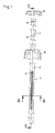
- the in the pictures Fig. 1 and 2 illustrated device for intracorporeal application of medical aids consists essentially of a hollow outer application tube 1 and an insertable into the application tube 1 and slidable in the longitudinal direction of the application tube 1 winding insert.
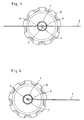
- the setting of the medical device 3 on the winding insert 2 takes place in the in Fig. 3 illustrated first embodiment of a formed in the winding insert 2 through slot 4 through which the medical device 3 is pushed through until the medical device 3 protrudes on both sides, preferably of equal length, from the slot 4.
- By turning the winding insert 2 can now be the medical device 3 double-wound on the winding insert 2, as shown schematically in FIG Fig. 5 is shown.
- One area of application for this device is, for example, hernia surgeries in which the medical device is designed as a mesh or mesh implant consisting of the body's own or exogenous tissue in order to bridge the corresponding fascia gap.
- window-like opening 6 is formed, through which the medical device 3 can be inserted for fixing the winding insert 2 in the application tube 1, as in Fig. 1 is shown.
- the window-like opening 6 is formed as a gap 6, but other embodiments are possible, which allow the medical device 3 to insert the winding insert 2 in the application tube 1 to introduce.
- Fig. 4 and 6 illustrated embodiment in which the medical device 3 is wrapped around the winding insert 2 catchy, it is sufficient to form only a gap 6 in the application tube 1.
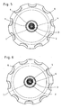
- the in the pictures Fig. 4 and 6 differ in terms of formed in the winding insert 2 slots 4 and 5. While according to Fig. 4 in the winding insert 2, only one slot 5 is formed, in which one end of the medical device 3 can be inserted, is in accordance with the embodiment Fig. 6 formed in the winding insert 2, a continuous slot 4, through which the medical device 3 can be pushed.
- This embodiment offers the medical aid 3 fixed to the winding insert 2 better hold than the use of the non-continuous slot 5.
- each locking step 9 corresponds to a certain insertion depth of the winding insert 2 in the application tube 1 and marks a corresponding operation.
- the application tube 1 together with the inserted winding insert 2, for example via a trocar sleeve in the operating area introduced.
- the winding insert 2 is now pressed into the application tube 2 up to the third latching step 9, in which the winding insert 2 wrapped with the medical device 3 to be applied emerges distally from the application tube 1 again.
- the medical device 3 can be detected, for example by means of a forceps.
- the medical aid 3 can now be easily and safely unwound in place from the winding insert 2 and applied to the surgical site to be supplied.
- Such a device designed for intracorporeal application of medical aids 3 is characterized in that it ensures a safe and gentle transport of the medical device 3 to be applied to the surgical site with a simple structure and simple handling.
Landscapes
- Health & Medical Sciences (AREA)
- Life Sciences & Earth Sciences (AREA)
- Animal Behavior & Ethology (AREA)
- General Health & Medical Sciences (AREA)
- Veterinary Medicine (AREA)
- Engineering & Computer Science (AREA)
- Biomedical Technology (AREA)
- Heart & Thoracic Surgery (AREA)
- Public Health (AREA)
- Surgery (AREA)
- Pathology (AREA)
- Molecular Biology (AREA)
- Medical Informatics (AREA)
- Nuclear Medicine, Radiotherapy & Molecular Imaging (AREA)
- Epidemiology (AREA)
- Vascular Medicine (AREA)
- Surgical Instruments (AREA)
- Accommodation For Nursing Or Treatment Tables (AREA)
- Orthopedics, Nursing, And Contraception (AREA)
- Medicinal Preparation (AREA)
- Prostheses (AREA)
- Media Introduction/Drainage Providing Device (AREA)
Abstract
Description
Die Erfindung betrifft eine_Vorrichtung zur intrakorporalen Applikation medizinischer Hilfsmittel, insbesondere Plastiken und Wundauflagen, mit einem hohlen Applikationsrohr zum Einbringen des medizinischen Hilfsmittels in das Operationsgebiet.The invention relates to a device for the intracorporeal application of medical aids, in particular plastics and wound dressings, with a hollow application tube for introducing the medical device into the operating area.
In verschiedenen Bereichen der Chirurgie, insbesondere der endoskopischen Chirurgie, ist es erforderlich medizinische Hilfsmittel, wie beispielsweise Wundauflagen oder Plastiken, in das Operationsgebiet einzubringen und vor Ort unter beengten Verhältnissen zu applizieren.In various areas of surgery, in particular endoscopic surgery, it is necessary to introduce medical aids, such as wound dressings or plastics, into the operating area and to apply them in confined spaces on site.
So ist es beispielsweise bekannt bei Hernien-Operationen (Leistenbruch-OP) die zu verschließende Faszienlücke mittels eines netzartigen Gewebes zu überbrücken, das über eine Trokarhülse in das Operationsgebiet eingebracht wird. Hierzu wird das Gewebenetz von Hand zusammengerollt oder gefaltet und in die Trokarhülse gesteckt und mittels einer Fasszange zum Operationsgebiet geschoben. Nachteilig an dieser beschriebenen Vorgehensweise ist neben dem großen manuellen Aufwand für das Rollen oder Falten und anschließende Einbringen des solchermaßen verkleinerten Gewebes in die Trokarhülse die Gefahr, dass das Gewebe beim Einschieben in die Trokarhülse beschädigt wird.Thus, it is known, for example, in hernia operations (inguinal hernia surgery) to bridge the fascia gap to be closed by means of a net-like tissue which is introduced into the surgical area via a trocar sleeve. For this purpose, the tissue mesh is rolled or folded by hand and inserted into the trocar sleeve and pushed by means of a forceps to the operation area. A disadvantage of this procedure described in addition to the large manual effort for rolling or folding and subsequent introduction of the thus reduced tissue in the trocar sleeve the risk that the tissue is damaged when inserted into the trocar sleeve.
Davon ausgehend liegt der Erfindung die Aufgabe zugrunde, eine Vorrichtung zur intrakorporalen Applikation medizinischer Hilfsmittel, zu schaffen, die bei einfacher Handhabung eine sichere Applikation des medizinischen Hilfsmittels im Operationsgebiet gewährleistet.On this basis, the invention is based on the object to provide a device for intracorporeal application of medical aids, which ensures simple handling a secure application of the medical aid in the operation area.
Die L ö s u n g dieser Aufgabenstellung ist erfindungsgemäß gekennzeichnet durch einen in das hohle Applikationsrohr einsetzbaren und in Längsrichtung des Applikationsrohres verschiebbaren Wickeleinsatz, auf den das zu applizierende medizinische Hilfsmittel aufwickelbar ist.The solution of this problem is inventively characterized by an insertable into the hollow application tube and slidable in the longitudinal direction of the application tube winding insert on which the medical device to be applied can be wound up.
Durch die erfindungsgemäße Verwendung des in das Applikationsrohr einsetzbaren Wickeleinsatzes ist es erstmalig möglich, auf ein manuelles Rollen oder Falten des zu applizierenden medizinischen Hilfsmittels zu verzichten. Der Wickeleinsatz mitsamt dem auf den Wickeleinsatz aufgewickelten medizinischen Hilfsmittel ist überdies in Längsrichtung des Applikationsrohres verschiebbar, um das medizinische Hilfsmittel zum Operationsgebiet hin zu verschieben.By using the winding insert insertable into the application tube according to the invention, it is possible for the first time to dispense with manual rolling or folding of the medical aid to be applied. The winding insert together with the wound on the winding insert medical aids is also displaced in the longitudinal direction of the application tube to move the medical aid to the operating area out.
Mit einer praktischen Ausführungsform der Erfindung wird vorgeschlagen, dass der Wickeleinsatz und das Applikationsrohr im ineinandergesetzten Zustand um die Instrumentenlängsachse gegeneinander verdrehbar sind. Diese gegenseitige Verdrehbarkeit der Bauteile erleichtert das Auf- und Abwickeln des medizinischen Hilfsmittels auf den Wickeleinsatz bzw. vom Wickeleinsatz herunter.With a practical embodiment of the invention, it is proposed that the winding insert and the application tube can be rotated relative to one another around the longitudinal axis of the instrument when they are placed in one another. This mutual rotatability of the components facilitates the winding and unwinding of the medical aid on the winding insert or from the winding insert down.
Zum Festlegen des medizinischen Hilfsmittels am Wickeleinsatz wird mit einer ersten Ausführungsform der Erfindung vorgeschlagen, dass das medizinische Hilfsmittel am Wickeleinsatz festlegbar ist, beispielsweise durch Ausbildung eines Schlitzes im Wickeleinsatz zur Aufnahme eines Endes des medizinischen Hilfsmittels.To set the medical device on the winding insert is proposed with a first embodiment of the invention that the medical device on the winding insert can be fixed, for example by forming a slot in the winding insert for receiving an end of the medical device.
Gemäß einer alternativen Ausgestaltungsform erfolgt das Festlegen des medizinischen Hilfsmittels am Wickeleinsatz über einen im Wickeleinsatz ausgebildeten durchgehenden Schlitz, in den das medizinische Hilfsmittel einsetzbar ist.According to an alternative embodiment, the setting of the medical aid on the winding insert via a formed in the winding insert through slot, in which the medical aid is used.
Gemäß einer praktischen Ausführungsform der Erfindung wird vorgeschlagen, dass der Wickeleinsatz zumindest im das medizinische Hilfsmittel aufnehmenden Bereich als in das Applikationsrohr einsetzbarer Drahtstift, vorzugsweise aus einem Ni-Ti-Werkstoff, ausgebildet ist.According to a practical embodiment of the invention, it is proposed that the winding insert, at least in the area receiving the medical aid, is designed as a wire pin which can be inserted into the application tube, preferably made of a Ni-Ti material.
Um das Handhaben der erfindungsgemäßen Vorrichtung zu erleichtern, wird mit der Erfindung weiterhin vorgeschlagen, dass der Wickeleinsatz in vorgegebenen Raststufen in axialer Richtung in das Applikationsrohr einsetzbar ist. Diese Raststufen stellen vorgegebene Einstecktiefen des Wickeleinsatzes in das Applikationsrohr, beispielsweise eine Einführ- und eine Applikationsstellung, dar und ermöglichen so ein sicheres und gleichmäßiges Bedienen der Vorrichtung.In order to facilitate the handling of the device according to the invention, it is further proposed with the invention that the winding insert can be inserted into the application tube in predetermined latching steps in the axial direction. These rest stops provide predetermined insertion depths of the winding insert into the application tube, for example, an insertion and an application position, and thus enable a secure and uniform operation of the device.
Weiterhin wird mit der Erfindung vorgeschlagen, dass im Applikationsrohr mindestens eine in Axialrichtung verlaufende Öffnung zum Einführen des medizinischen Hilfsmittels ausgebildet ist. Diese fensterartige Öffnung im Applikationsrohr ermöglicht das Festlegen des medizinischen Hilfsmittels am Wickeleinsatz bei in das Applikationsrohr eingesetztem Wickeleinsatz. Hierzu wird das medizinische Hilfsmittel durch die Öffnung in das Innere des Applikationsrohres geführt und beispielsweise mit einem Ende im Schlitz des Wickeleinsatzes festgelegt. Durch nachfolgendes Verdrehen des Wickeleinsatzes und/oder des Applikationsrohres wird das medizinische Hilfsmittel in das Applikationsrohr eingezogen und um den Wickeleinsatz gewickelt.Furthermore, it is proposed with the invention that at least one opening extending in the axial direction is formed in the application tube for introducing the medical aid. This window-like opening in the application tube makes it possible to fix the medical aid on the winding insert when the winding insert is inserted into the application tube. For this purpose, the medical device is guided through the opening into the interior of the application tube and fixed, for example, with one end in the slot of the winding insert. By subsequent rotation of the winding insert and / or the application tube, the medical aid is drawn into the application tube and wound around the winding insert.
Gemäß einer praktischen Ausführungsform der Erfindung sind im Applikationsrohr zwei einander in etwa gegenüberliegende, in Axialrichtung verlaufende Öffnungen ausgebildet. Insbesondere bei großen respektive langen medizinischen Hilfsmitteln ist diese Ausgestaltungsform vorteilhaft, da es ein schnelleres Aufwickeln des medizinischen Hilfsmittels auf den Wickeleinsatz ermöglicht. Hierzu wird das medizinische Hilfsmittel durch eine Öffnung in das Innere des Applikationsrohres geführt und durch den durchgehenden Schlitz des Wickeleinsatzes hindurchgezogen, bis das medizinische Hilfsmittel aus der gegenüberliegenden Öffnung des Applikationsrohres wieder aus dem Applikationsrohr austritt. Durch nachfolgendes Verdrehen des Wickeleinsatzes und/oder des Applikationsrohres wird das medizinische Hilfsmittel in das Applikationsrohr eingezogen und doppelgängig um den Wickeleinsatz gewickelt.According to a practical embodiment of the invention, two mutually approximately, axially extending openings are formed in the application tube. In particular, in the case of large or long medical aids, this embodiment is advantageous because it allows a faster winding of the medical device on the winding insert. For this purpose, the medical device is guided through an opening in the interior of the application tube and pulled through the continuous slot of the winding insert until the medical device emerges from the opposite opening of the application tube again from the application tube. By subsequent rotation of the winding insert and / or the application tube, the medical aid is drawn into the application tube and wound double-wound around the winding insert.
Das Bedienen des Applikationsrohres und des Wickeleinsatzes, insbesondere beim gegenseitigen Verdrehen der Bauteile, kann erfindungsgemäß dadurch erleichtert werden, dass am proximalen Ende des Applikationsrohres und/oder des Wickeleinsatzes ein Handgriff angeordnet ist.The operation of the application tube and the winding insert, in particular in the mutual rotation of the components, according to the invention can be facilitated by the fact that a handle is arranged at the proximal end of the application tube and / or the winding insert.
Schließlich wird mit der Erfindung vorgeschlagen, dass das medizinische Hilfsmittel eine Netzplastik für eine Hernien-OP oder dergleichen ist. Bei der Hernien-OP werden die aus körpereigenem oder körperfremdem Gewebe bestehenden Netzplastiken oder Netzimplantate verwendet, um die entsprechende Faszienlücke zu überbrücken.Finally, it is proposed with the invention that the medical aid is a mesh for hernia surgery or the like. At the hernia surgery meshes or mesh implants consisting of the body's own or exogenous tissue are used to bridge the corresponding fascia gap.
Weitere Merkmale und Vorteile der Erfindung ergeben sich anhand der zugehörigen Zeichnung, in der zwei Ausführungsbeispiele einer erfindungsgemäßen Vorrichtung zur intrakorporalen Applikation medizinischer Hilfsmittel nur beispielhaft dargestellt sind, ohne die Erfindung auf diese Ausführungsbeispiele zu beschränken. In der Zeichnung zeigt:
- Fig. 1
- eine Seitenansicht einer erfindungsgemäßen Vorrichtung zur intrakorporalen Applikation medizinischer Hilfsmittel;
- Fig. 2
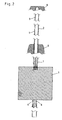
- einen Längsschnitt entlang der Linie II-II gemäß
Fig. 1 ; - Fig. 3
- einen vergrößerten Querschnitt entlang der Linie III-III gemäß
Fig. 1 ; - Fig. 4
- eine
Fig. 3 entsprechende Schnittansicht, jedoch eine zweite erfindungsgemäße Ausführungsform darstellend; - Fig. 5
- eine schematische Darstellung der Aufwicklung des medizinischen Hilfsmittels auf einen Wickeleinsatz gemäß
Fig. 3 und - Fig. 6
- eine schematische Darstellung der Aufwicklung des medizinischen Hilfsmittels auf einen Wickeleinsatz gemäß
Fig. 4 .
- Fig. 1
- a side view of a device according to the invention for intracorporeal application of medical aids;
- Fig. 2
- a longitudinal section along the line II-II according to
Fig. 1 ; - Fig. 3
- an enlarged cross section along the line III-III according to
Fig. 1 ; - Fig. 4
- a
Fig. 3 corresponding sectional view, but showing a second embodiment of the invention; - Fig. 5
- a schematic representation of the winding of the medical device on a winding insert according to
Fig. 3 and - Fig. 6
- a schematic representation of the winding of the medical device on a winding insert according to
Fig. 4 ,
Die in den Abbildungen
Wie insbesondere aus
Das Festlegen des medizinischen Hilfsmittels 3 am Wickeleinsatz 2 erfolgt bei der in
Gemäß der in
Bei den medizinischen Hilfsmitteln 3 kann es sich beispielsweise um Wundauflagen oder Plastiken handeln, die in zusammengelegter Form in das Operationsgebiet eingebracht werden und erst an Ort und Stelle am Operationsgebiet ausgebreitet und auf den entsprechenden Anwendungsort aufgebracht werden.The
Ein Anwendungsgebiet für diese Vorrichtung stellen beispielsweise Hernien-Operationen dar, bei denen das medizinische Hilfsmittel als aus körpereigenem oder körperfremdem Gewebe bestehende Netzplastik oder Netzimplantatausgebildet ist, um die entsprechende Faszienlücke zu überbrücken.One area of application for this device is, for example, hernia surgeries in which the medical device is designed as a mesh or mesh implant consisting of the body's own or exogenous tissue in order to bridge the corresponding fascia gap.
In Betracht kommen aber prinzipiell alle chirurgischen Anwendungsbereiche, bei denen eine Wundstelle oder Öffnung mittels eines flächigen medizinischen Hilfsmittels 3 überbrückt und/oder verschlossen werden soll, wie beispielsweise bei der Chirurgie im Bauchraum bei Magen- oder Darmdurchbrüchen oder in der Fetoskopie zum Verschließen der Spina bifida. Aber auch die intrakorporale Versorgung von Wunden, beispielsweise fetaler Kopfwunden, mit Pflastern und dergleichen flächigen Wundauflagen ist mit dieser Vorrichtung möglich.In principle, however, all surgical application areas come into consideration, in which a wound site or opening is to be bridged and / or closed by means of a planar
Neben der Möglichkeit, das medizinische Hilfsmittel 3 außerhalb des Applikationsrohres 1 auf den Wickeleinsatz 2 aufzuwickeln und erst nachfolgend den mit dem medizinischen Hilfsmittel 3 umwickelten Wickeleinsatz 2 in das Applikationsrohr 1 einzuführen, besteht die bevorzugte und in den Abbildungen
Hierzu ist in der Mantelfläche des Applikationsrohres 1 mindestens eine in Axialrichtung des Applikationsrohres 1 verlaufende fensterartige Öffnung 6 ausgebildet, durch die das medizinische Hilfsmittel 3 zum Festelegen am Wickeleinsatz 2 in das Applikationsrohr 1 einführbar ist, wie dies in
Für die in
Die in
Das Aufwickeln des solchermaßen am Wickeleinsatz 2 festgelegten medizinischen Hilfsmittels 3 auf den Wickeleinsatz 2 erfolgt nachfolgend durch Drehen des Wickeleinsatzes 2 und/oder des Applikationsrohres 1 um die Instrumentenlängsachse 7, wobei für den Fall, dass beide Bauteile 1 und 2 gedreht werden, das Applikationsrohr 1 und der Wickeleinsatz 2 gegenläufig gedreht werden müssen. Durch diese Drehung mindestens eines Bauteils 1 oder 2 relativ zu dem anderen Bauteil 2 oder 1 wird das am Wickeleinsatz 2 festgelegte medizinische Hilfsmittel 3 in das Applikationsrohr 1 hineingezogen und lagenweise um den Wickeleinsatz 2 gewickelt.The winding of the thus defined on the winding
Um sicherzustellen, dass der Wickeleinsatz 2 auch noch mit dem darauf aufgewickelten medizinischen Hilfsmittel 3 im Applikationsrohr 1 axialverschiebbar ist, ist der Wickeleinsatz 2 zumindest im das medizinische Hilfsmittel 3 aufnehmenden Bereich als den Durchmesser des Wickeleinsatzes 2 reduzierender Drahtstift ausgebildet, wie dies der Abbildung
In den übrigen Teilbereichen ist der Wickeleinsatz 2 vorteilhafterweise rohrförmig ausgebildet, wobei der Außendurchmesser des Wickeleinsatzes 2 im Wesentlichen dem Innendurchmesser des Applikationsrohres 1 entspricht, um eine gute und verkantungsfreie Führung des Wickeleinsatzes 2 im Applikationsrohr 1 zu gewährleisten.In the other sub-areas of the winding
Das Bedienen des Applikationsrohres 1 und des Wickeleinsatzes 2, insbesondere das Verdrehen der Bauteile 1 und 2, wird bei der dargestellten Ausführungsform dadurch erleichtert, dass am proximalen Ende sowohl des Applikationsrohres 1 als auch des Wickeleinsatzes 2 jeweils ein möglichst ergonomisch ausgestalteter Handgriff 8 angeordnet ist.The operation of the
Das Zusammensetzen und Bedienen der wie voranstehend beschrieben aufgebauten Vorrichtung zur intrakorporalen Applikation medizinischer Hilfsmittel geschieht wie folgt:
- Im ersten Arbeitsschritt wird der
Wickeleinsatz 2 mit dem distalen Ende voran vom proximalen Ende her indas hohle Applikationsrohr 1 gesteckt,bis der Wickeleinsatz 2 die inFig. 1 dargestellte Position einnimmt, in derder im Wickeleinsatz 2 ausgebildete durchgehende Schlitz 4, oder auch nur der einseitige Schlitz 5, im Bereich des mindestens einen fensterartigen Spalts 6 des Applikationsrohres 1 angeordnet ist.
- In the first step, the winding
insert 2 is inserted with the distal end in front of the proximal end into thehollow application tube 1 until the windinginsert 2, the inFig. 1 shown position in which the windinginsert 2 formed in thecontinuous slot 4, or even the single-sided slot 5, in the region of the at least one window-like gap 6 of theapplication tube 1 is arranged.
Um für diesen ersten Arbeitsschritt und auch die nachfolgenden Arbeitsschritte immer die richtige Einstecktiefe des Wickeleinsatzes 2 in das Applikationsrohr 1 einzuhalten, sind, wie aus
Nach dem Einführen des Wickeleinsatzes 2 in das Applikationsrohr 1 bis zu der zuvor beschriebenen ersten Raststufe wird nachfolgend das medizinische Hilfsmittel 3 am Wickeleinsatz 2 festgelegt, beispielsweise durch Hindurchstecken durch den durchgehenden Schlitz 4, wie dies in
Im nächsten Schritt wird der mit dem aufgewickelten medizinischen Hilfsmittel 3 versehene Wickeleinsatz 2 in distaler Richtung weiter in das Applikationsrohr 1 hineingeschoben, bis eine zweite Raststufe 9 erreicht ist, in der das medizinische Hilfsmittel 3 im Inneren des Applikationsrohres 1 angeordnet ist und nicht wieder über den mindestens einen Spalt 6 des Applikationsrohres 1 von dem Wickeleinsatz 2 abgewickelt werden kann.In the next step, the winding
In dieser Arbeitsstellung wird das Applikationsrohr 1 mitsamt dem eingesteckten Wickeleinsatz 2, beispielsweise über eine Trokarhülse in das Operationsgebiet eingeführt. Im Operationsgebiet wird der Wickeleinsatz 2 nunmehr bis zur dritten Raststufe 9 in das Applikationsrohr 2 hineingedrückt, in der der mit dem zu applizierenden medizinischen Hilfsmittel 3 umwickelte Wickeleinsatz 2 distalseitig wieder aus dem Applikationsrohr 1 heraustritt. Nun kann das medizinische Hilfsmittel 3 beispielsweise mittels einer Fasszange erfasst werden. Durch Drehen des Wickeleinsatzes 2 lässt sich das medizinische Hilfsmittel 3 nunmehr einfach und sicher an Ort und Stelle vom Wickeleinsatz 2 abwickeln und auf die zu versorgende Operationsstelle aufbringen.In this working position, the
Eine solchermaßen ausgebildete Vorrichtung zur intrakorporalen Applikation medizinischer Hilfsmittel 3 zeichnet sich dadurch aus, dass sie bei einfachem Aufbau und einfacher Handhabung einen sicheren und schonenden Transport des zu applizierenden medizinischen Hilfsmittels 3 hin zur Operationsstelle gewährleistet.Such a device designed for intracorporeal application of
- 11
- Applikationsrohrapplication tube
- 22
- Wickeleinsatzwrapping bit
- 33
- medizinisches Hilfsmittelmedical aid
- 44
- Schlitz (durchgehend)Slot (continuous)
- 55
- Schlitzslot
- 66
- Öffnung / SpaltOpening / gap
- 77
- Instrumentenlängsachseinstrument longitudinal axis
- 88th
- Handgriffhandle
- 99
- Raststufecatching step
Claims (11)
einen in das hohle Applikationsrohr (1) einsetzbaren und in Längsrichtung des Applikationsrohres (1) verschiebbaren Wickeleinsatz (2), auf den das zu applizierende medizinische Hilfsmittel (3) aufwickelbar ist.Device for intracorporeal application of medical aids, in particular plastics and wound dressings, with a hollow application tube (1) for introducing the medical aid (3) into the surgical area, characterized by
a winding insert (2) which can be inserted into the hollow application tube (1) and which can be displaced in the longitudinal direction of the application tube (1), onto which the medical aid (3) to be applied can be wound up.
Applications Claiming Priority (1)
| Application Number | Priority Date | Filing Date | Title |
|---|---|---|---|
| DE102007032482A DE102007032482A1 (en) | 2007-07-12 | 2007-07-12 | Device for intracorporeal application of medical aids |
Publications (3)
| Publication Number | Publication Date |
|---|---|
| EP2014331A2 true EP2014331A2 (en) | 2009-01-14 |
| EP2014331A3 EP2014331A3 (en) | 2009-01-21 |
| EP2014331B1 EP2014331B1 (en) | 2010-03-10 |
Family
ID=39865043
Family Applications (1)
| Application Number | Title | Priority Date | Filing Date |
|---|---|---|---|
| EP08012342A Active EP2014331B1 (en) | 2007-07-12 | 2008-07-09 | Device for intracorporal application of medical aids |
Country Status (4)
| Country | Link |
|---|---|
| US (1) | US8864779B2 (en) |
| EP (1) | EP2014331B1 (en) |
| AT (1) | ATE460202T1 (en) |
| DE (2) | DE102007032482A1 (en) |
Cited By (1)
| Publication number | Priority date | Publication date | Assignee | Title |
|---|---|---|---|---|
| EP2712580A1 (en) * | 2012-09-28 | 2014-04-02 | Covidien LP | Surgical implant and applicator |
Families Citing this family (1)
| Publication number | Priority date | Publication date | Assignee | Title |
|---|---|---|---|---|
| US10433018B2 (en) * | 2017-03-06 | 2019-10-01 | Tribune Broadcasting Company, Llc | Video production system with dynamic character generator output |
Citations (6)
| Publication number | Priority date | Publication date | Assignee | Title |
|---|---|---|---|---|
| US5263969A (en) * | 1992-04-17 | 1993-11-23 | Phillips Edward H | Tool for the laparoscopic introduction of a mesh prosthesis |
| EP0581036A1 (en) * | 1992-06-30 | 1994-02-02 | United States Surgical Corporation | Surgical element deployment apparatus |
| EP0625334A1 (en) * | 1993-05-21 | 1994-11-23 | Ethnor | Endoscopic installation assembly for soft tissue prosthesis |
| US5464403A (en) * | 1992-10-29 | 1995-11-07 | General Surgical Innovations, Inc. | Placement tool and method for laparoscopic hernia repair |
| US5814058A (en) * | 1993-03-05 | 1998-09-29 | Innerdyne, Inc. | Method and apparatus employing conformable sleeve for providing percutaneous access |
| WO2007056297A2 (en) * | 2005-11-07 | 2007-05-18 | Csh Innovations, Inc. | Surgical repair systems and methods of using the same |
Family Cites Families (13)
| Publication number | Priority date | Publication date | Assignee | Title |
|---|---|---|---|---|
| US5147316A (en) * | 1990-11-19 | 1992-09-15 | Castillenti Thomas A | Laparoscopic trocar with self-locking port sleeve |
| US5376376A (en) * | 1992-01-13 | 1994-12-27 | Li; Shu-Tung | Resorbable vascular wound dressings |
| US6312442B1 (en) * | 1992-06-02 | 2001-11-06 | General Surgical Innovations, Inc. | Method for developing an anatomic space for laparoscopic hernia repair |
| CA2166797A1 (en) * | 1993-07-12 | 1995-01-26 | Robert Schindler | Soft tissue augmentation apparatus |
| US5591207A (en) * | 1995-03-30 | 1997-01-07 | Linvatec Corporation | Driving system for inserting threaded suture anchors |
| WO1998041154A1 (en) * | 1997-03-20 | 1998-09-24 | Focal, Inc. | Biodegradable tissue retractor |
| US6419639B2 (en) * | 1999-08-05 | 2002-07-16 | National Institute Of Health | Laparoscopic SAC holder assembly |
| WO2002053073A1 (en) * | 2001-01-07 | 2002-07-11 | Erik Berndt | Wound dressing, glove and method for production of a wound dressing |
| DE10330660B3 (en) * | 2003-07-08 | 2004-10-21 | Richard Wolf Gmbh | Wound-closing device for stitching wounds comprises a through bore crossing the longitudinal axis of the device and extending through a proximal section from the proximal end to a transition region between the proximal and distal sections |
| US7846171B2 (en) * | 2004-05-27 | 2010-12-07 | C.R. Bard, Inc. | Method and apparatus for delivering a prosthetic fabric into a patient |
| EP2926765A3 (en) * | 2006-06-08 | 2015-12-23 | AMS Research Corporation | Apparatus for levator distension repair |
| US20090299352A1 (en) * | 2007-12-21 | 2009-12-03 | Boston Scientific Scimed, Inc. | Steerable laser-energy delivery device |
| US8317808B2 (en) * | 2008-02-18 | 2012-11-27 | Covidien Lp | Device and method for rolling and inserting a prosthetic patch into a body cavity |
-
2007
- 2007-07-12 DE DE102007032482A patent/DE102007032482A1/en not_active Withdrawn
-
2008
- 2008-07-09 EP EP08012342A patent/EP2014331B1/en active Active
- 2008-07-09 DE DE502008000428T patent/DE502008000428D1/en active Active
- 2008-07-09 AT AT08012342T patent/ATE460202T1/en active
- 2008-07-11 US US12/171,852 patent/US8864779B2/en active Active
Patent Citations (6)
| Publication number | Priority date | Publication date | Assignee | Title |
|---|---|---|---|---|
| US5263969A (en) * | 1992-04-17 | 1993-11-23 | Phillips Edward H | Tool for the laparoscopic introduction of a mesh prosthesis |
| EP0581036A1 (en) * | 1992-06-30 | 1994-02-02 | United States Surgical Corporation | Surgical element deployment apparatus |
| US5464403A (en) * | 1992-10-29 | 1995-11-07 | General Surgical Innovations, Inc. | Placement tool and method for laparoscopic hernia repair |
| US5814058A (en) * | 1993-03-05 | 1998-09-29 | Innerdyne, Inc. | Method and apparatus employing conformable sleeve for providing percutaneous access |
| EP0625334A1 (en) * | 1993-05-21 | 1994-11-23 | Ethnor | Endoscopic installation assembly for soft tissue prosthesis |
| WO2007056297A2 (en) * | 2005-11-07 | 2007-05-18 | Csh Innovations, Inc. | Surgical repair systems and methods of using the same |
Cited By (3)
| Publication number | Priority date | Publication date | Assignee | Title |
|---|---|---|---|---|
| EP2712580A1 (en) * | 2012-09-28 | 2014-04-02 | Covidien LP | Surgical implant and applicator |
| US9220586B2 (en) | 2012-09-28 | 2015-12-29 | Covidien Lp | Surgical implant and applicator |
| AU2013231071B2 (en) * | 2012-09-28 | 2017-09-28 | Covidien Lp | Surgical implant and applicator |
Also Published As
| Publication number | Publication date |
|---|---|
| EP2014331A3 (en) | 2009-01-21 |
| US20090024073A1 (en) | 2009-01-22 |
| US8864779B2 (en) | 2014-10-21 |
| ATE460202T1 (en) | 2010-03-15 |
| EP2014331B1 (en) | 2010-03-10 |
| DE502008000428D1 (en) | 2010-04-22 |
| DE102007032482A1 (en) | 2009-01-15 |
Similar Documents
| Publication | Publication Date | Title |
|---|---|---|
| EP2316351B1 (en) | Medical instrument for setting tissue clamps | |
| DE60200515T2 (en) | closure device | |
| DE60100507T2 (en) | Wound closure guide tool | |
| EP1683487B1 (en) | Device for closing a trocar puncture wound | |
| EP2316350B1 (en) | Resection device | |
| AT505002B1 (en) | DEVICE FOR USE IN THE TREATMENT OF A HEMORRHOIDENEPROLAP | |
| WO2005009254A1 (en) | Method and device for the endoscopic application of self-closing medical clips | |
| DE102011102686A1 (en) | Anastomosis device and method for introducing an anastomosis device into a body lumen | |
| EP3025760B1 (en) | Design for simplified removal of a balloon applicator | |
| EP2952222A1 (en) | Balloon catheter with an insertion aid for a guide wire | |
| EP2014331B1 (en) | Device for intracorporal application of medical aids | |
| WO2019229206A1 (en) | Controllable insertion sleeve | |
| EP2994057B1 (en) | Surgical needle with detachable tip and suture integrated into its hollow core | |
| EP2903494A1 (en) | Disposable endoscopy and biopsy system | |
| DE202011101205U1 (en) | Anastomosegerät | |
| EP3400914A1 (en) | Handle for a catheter and corresponding catheter | |
| DE19707851C2 (en) | Needle instrument | |
| DE19515761A1 (en) | Device for improved handling of guidewires, especially for catheter examinations | |
| WO2021233740A1 (en) | Tissue clip application fitting or retrofitting set | |
| DE3831398A1 (en) | Surgical kit | |
| EP2910221B1 (en) | Release device for releasing a medical implant from a catheter, and catheter comprising a release device | |
| EP3009088B1 (en) | Trocar sleeve with an asymmetric helix | |
| DE19860304B4 (en) | Anastomotic system consisting of a resorbable anastomosis protection | |
| DE19916602C1 (en) | Medical drain insertion device has drain fitted to end of guide catheter and slid relative to latter by displacement catheter mechanically coupled to drain by endless loop | |
| WO2022069560A1 (en) | Amplatz sheath and dilation system |
Legal Events
| Date | Code | Title | Description |
|---|---|---|---|
| PUAI | Public reference made under article 153(3) epc to a published international application that has entered the european phase |
Free format text: ORIGINAL CODE: 0009012 |
|
| PUAL | Search report despatched |
Free format text: ORIGINAL CODE: 0009013 |
|
| AK | Designated contracting states |
Kind code of ref document: A2 Designated state(s): AT BE BG CH CY CZ DE DK EE ES FI FR GB GR HR HU IE IS IT LI LT LU LV MC MT NL NO PL PT RO SE SI SK TR |
|
| AX | Request for extension of the european patent |
Extension state: AL BA MK RS |
|
| AK | Designated contracting states |
Kind code of ref document: A3 Designated state(s): AT BE BG CH CY CZ DE DK EE ES FI FR GB GR HR HU IE IS IT LI LT LU LV MC MT NL NO PL PT RO SE SI SK TR |
|
| AX | Request for extension of the european patent |
Extension state: AL BA MK RS |
|
| RIN1 | Information on inventor provided before grant (corrected) |
Inventor name: BLOCHER, MARTIN Inventor name: KOHL, PROF.DR. THOMAS |
|
| 17P | Request for examination filed |
Effective date: 20090711 |
|
| AKX | Designation fees paid |
Designated state(s): AT BE BG CH CY CZ DE DK EE ES FI FR GB GR HR HU IE IS IT LI LT LU LV MC MT NL NO PL PT RO SE SI SK TR |
|
| GRAP | Despatch of communication of intention to grant a patent |
Free format text: ORIGINAL CODE: EPIDOSNIGR1 |
|
| GRAS | Grant fee paid |
Free format text: ORIGINAL CODE: EPIDOSNIGR3 |
|
| GRAA | (expected) grant |
Free format text: ORIGINAL CODE: 0009210 |
|
| AK | Designated contracting states |
Kind code of ref document: B1 Designated state(s): AT BE BG CH CY CZ DE DK EE ES FI FR GB GR HR HU IE IS IT LI LT LU LV MC MT NL NO PL PT RO SE SI SK TR |
|
| REG | Reference to a national code |
Ref country code: GB Ref legal event code: FG4D Free format text: NOT ENGLISH |
|
| REG | Reference to a national code |
Ref country code: CH Ref legal event code: EP |
|
| REG | Reference to a national code |
Ref country code: IE Ref legal event code: FG4D |
|
| REF | Corresponds to: |
Ref document number: 502008000428 Country of ref document: DE Date of ref document: 20100422 Kind code of ref document: P |
|
| REG | Reference to a national code |
Ref country code: NL Ref legal event code: VDEP Effective date: 20100310 |
|
| PG25 | Lapsed in a contracting state [announced via postgrant information from national office to epo] |
Ref country code: HR Free format text: LAPSE BECAUSE OF FAILURE TO SUBMIT A TRANSLATION OF THE DESCRIPTION OR TO PAY THE FEE WITHIN THE PRESCRIBED TIME-LIMIT Effective date: 20100310 Ref country code: LT Free format text: LAPSE BECAUSE OF FAILURE TO SUBMIT A TRANSLATION OF THE DESCRIPTION OR TO PAY THE FEE WITHIN THE PRESCRIBED TIME-LIMIT Effective date: 20100310 Ref country code: NO Free format text: LAPSE BECAUSE OF FAILURE TO SUBMIT A TRANSLATION OF THE DESCRIPTION OR TO PAY THE FEE WITHIN THE PRESCRIBED TIME-LIMIT Effective date: 20100610 |
|
| LTIE | Lt: invalidation of european patent or patent extension |
Effective date: 20100310 |
|
| PG25 | Lapsed in a contracting state [announced via postgrant information from national office to epo] |
Ref country code: SI Free format text: LAPSE BECAUSE OF FAILURE TO SUBMIT A TRANSLATION OF THE DESCRIPTION OR TO PAY THE FEE WITHIN THE PRESCRIBED TIME-LIMIT Effective date: 20100310 Ref country code: FI Free format text: LAPSE BECAUSE OF FAILURE TO SUBMIT A TRANSLATION OF THE DESCRIPTION OR TO PAY THE FEE WITHIN THE PRESCRIBED TIME-LIMIT Effective date: 20100310 Ref country code: LV Free format text: LAPSE BECAUSE OF FAILURE TO SUBMIT A TRANSLATION OF THE DESCRIPTION OR TO PAY THE FEE WITHIN THE PRESCRIBED TIME-LIMIT Effective date: 20100310 Ref country code: PL Free format text: LAPSE BECAUSE OF FAILURE TO SUBMIT A TRANSLATION OF THE DESCRIPTION OR TO PAY THE FEE WITHIN THE PRESCRIBED TIME-LIMIT Effective date: 20100310 |
|
| REG | Reference to a national code |
Ref country code: IE Ref legal event code: FD4D |
|
| PG25 | Lapsed in a contracting state [announced via postgrant information from national office to epo] |
Ref country code: ES Free format text: LAPSE BECAUSE OF FAILURE TO SUBMIT A TRANSLATION OF THE DESCRIPTION OR TO PAY THE FEE WITHIN THE PRESCRIBED TIME-LIMIT Effective date: 20100621 Ref country code: CY Free format text: LAPSE BECAUSE OF FAILURE TO SUBMIT A TRANSLATION OF THE DESCRIPTION OR TO PAY THE FEE WITHIN THE PRESCRIBED TIME-LIMIT Effective date: 20100310 Ref country code: NL Free format text: LAPSE BECAUSE OF FAILURE TO SUBMIT A TRANSLATION OF THE DESCRIPTION OR TO PAY THE FEE WITHIN THE PRESCRIBED TIME-LIMIT Effective date: 20100310 Ref country code: SE Free format text: LAPSE BECAUSE OF FAILURE TO SUBMIT A TRANSLATION OF THE DESCRIPTION OR TO PAY THE FEE WITHIN THE PRESCRIBED TIME-LIMIT Effective date: 20100310 Ref country code: RO Free format text: LAPSE BECAUSE OF FAILURE TO SUBMIT A TRANSLATION OF THE DESCRIPTION OR TO PAY THE FEE WITHIN THE PRESCRIBED TIME-LIMIT Effective date: 20100310 Ref country code: EE Free format text: LAPSE BECAUSE OF FAILURE TO SUBMIT A TRANSLATION OF THE DESCRIPTION OR TO PAY THE FEE WITHIN THE PRESCRIBED TIME-LIMIT Effective date: 20100310 Ref country code: GR Free format text: LAPSE BECAUSE OF FAILURE TO SUBMIT A TRANSLATION OF THE DESCRIPTION OR TO PAY THE FEE WITHIN THE PRESCRIBED TIME-LIMIT Effective date: 20100611 |
|
| PG25 | Lapsed in a contracting state [announced via postgrant information from national office to epo] |
Ref country code: BG Free format text: LAPSE BECAUSE OF FAILURE TO SUBMIT A TRANSLATION OF THE DESCRIPTION OR TO PAY THE FEE WITHIN THE PRESCRIBED TIME-LIMIT Effective date: 20100610 Ref country code: IS Free format text: LAPSE BECAUSE OF FAILURE TO SUBMIT A TRANSLATION OF THE DESCRIPTION OR TO PAY THE FEE WITHIN THE PRESCRIBED TIME-LIMIT Effective date: 20100710 Ref country code: CZ Free format text: LAPSE BECAUSE OF FAILURE TO SUBMIT A TRANSLATION OF THE DESCRIPTION OR TO PAY THE FEE WITHIN THE PRESCRIBED TIME-LIMIT Effective date: 20100310 Ref country code: SK Free format text: LAPSE BECAUSE OF FAILURE TO SUBMIT A TRANSLATION OF THE DESCRIPTION OR TO PAY THE FEE WITHIN THE PRESCRIBED TIME-LIMIT Effective date: 20100310 |
|
| PLBE | No opposition filed within time limit |
Free format text: ORIGINAL CODE: 0009261 |
|
| STAA | Information on the status of an ep patent application or granted ep patent |
Free format text: STATUS: NO OPPOSITION FILED WITHIN TIME LIMIT |
|
| BERE | Be: lapsed |
Owner name: KARL STORZ G.M.B.H. & CO. KG Effective date: 20100731 |
|
| PG25 | Lapsed in a contracting state [announced via postgrant information from national office to epo] |
Ref country code: DK Free format text: LAPSE BECAUSE OF FAILURE TO SUBMIT A TRANSLATION OF THE DESCRIPTION OR TO PAY THE FEE WITHIN THE PRESCRIBED TIME-LIMIT Effective date: 20100310 Ref country code: IE Free format text: LAPSE BECAUSE OF FAILURE TO SUBMIT A TRANSLATION OF THE DESCRIPTION OR TO PAY THE FEE WITHIN THE PRESCRIBED TIME-LIMIT Effective date: 20100310 |
|
| 26N | No opposition filed |
Effective date: 20101213 |
|
| PG25 | Lapsed in a contracting state [announced via postgrant information from national office to epo] |
Ref country code: MC Free format text: LAPSE BECAUSE OF NON-PAYMENT OF DUE FEES Effective date: 20100731 |
|
| PG25 | Lapsed in a contracting state [announced via postgrant information from national office to epo] |
Ref country code: BE Free format text: LAPSE BECAUSE OF NON-PAYMENT OF DUE FEES Effective date: 20100731 |
|
| PG25 | Lapsed in a contracting state [announced via postgrant information from national office to epo] |
Ref country code: MT Free format text: LAPSE BECAUSE OF FAILURE TO SUBMIT A TRANSLATION OF THE DESCRIPTION OR TO PAY THE FEE WITHIN THE PRESCRIBED TIME-LIMIT Effective date: 20100310 |
|
| PG25 | Lapsed in a contracting state [announced via postgrant information from national office to epo] |
Ref country code: PT Free format text: LAPSE BECAUSE OF FAILURE TO SUBMIT A TRANSLATION OF THE DESCRIPTION OR TO PAY THE FEE WITHIN THE PRESCRIBED TIME-LIMIT Effective date: 20100810 Ref country code: HU Free format text: LAPSE BECAUSE OF FAILURE TO SUBMIT A TRANSLATION OF THE DESCRIPTION OR TO PAY THE FEE WITHIN THE PRESCRIBED TIME-LIMIT Effective date: 20100911 Ref country code: LU Free format text: LAPSE BECAUSE OF NON-PAYMENT OF DUE FEES Effective date: 20100709 |
|
| PG25 | Lapsed in a contracting state [announced via postgrant information from national office to epo] |
Ref country code: TR Free format text: LAPSE BECAUSE OF FAILURE TO SUBMIT A TRANSLATION OF THE DESCRIPTION OR TO PAY THE FEE WITHIN THE PRESCRIBED TIME-LIMIT Effective date: 20100310 |
|
| REG | Reference to a national code |
Ref country code: CH Ref legal event code: PL |
|
| PG25 | Lapsed in a contracting state [announced via postgrant information from national office to epo] |
Ref country code: CH Free format text: LAPSE BECAUSE OF NON-PAYMENT OF DUE FEES Effective date: 20120731 Ref country code: LI Free format text: LAPSE BECAUSE OF NON-PAYMENT OF DUE FEES Effective date: 20120731 |
|
| REG | Reference to a national code |
Ref country code: AT Ref legal event code: MM01 Ref document number: 460202 Country of ref document: AT Kind code of ref document: T Effective date: 20130709 |
|
| PG25 | Lapsed in a contracting state [announced via postgrant information from national office to epo] |
Ref country code: AT Free format text: LAPSE BECAUSE OF NON-PAYMENT OF DUE FEES Effective date: 20130709 |
|
| REG | Reference to a national code |
Ref country code: FR Ref legal event code: PLFP Year of fee payment: 9 |
|
| REG | Reference to a national code |
Ref country code: FR Ref legal event code: PLFP Year of fee payment: 10 |
|
| REG | Reference to a national code |
Ref country code: DE Ref legal event code: R081 Ref document number: 502008000428 Country of ref document: DE Owner name: KARL STORZ SE & CO. KG INTELLECTUAL PROPERTY, DE Free format text: FORMER OWNER: KARL STORZ GMBH & CO. KG, 78532 TUTTLINGEN, DE Ref country code: DE Ref legal event code: R082 Ref document number: 502008000428 Country of ref document: DE Representative=s name: HOFMEISTER, FRANK, DIPL.-ING., DE Ref country code: DE Ref legal event code: R081 Ref document number: 502008000428 Country of ref document: DE Owner name: KARL STORZ SE & CO. KG, DE Free format text: FORMER OWNER: KARL STORZ GMBH & CO. KG, 78532 TUTTLINGEN, DE |
|
| REG | Reference to a national code |
Ref country code: FR Ref legal event code: PLFP Year of fee payment: 11 |
|
| PGFP | Annual fee paid to national office [announced via postgrant information from national office to epo] |
Ref country code: IT Payment date: 20190624 Year of fee payment: 12 |
|
| PGFP | Annual fee paid to national office [announced via postgrant information from national office to epo] |
Ref country code: GB Payment date: 20190624 Year of fee payment: 12 |
|
| GBPC | Gb: european patent ceased through non-payment of renewal fee |
Effective date: 20200709 |
|
| PG25 | Lapsed in a contracting state [announced via postgrant information from national office to epo] |
Ref country code: GB Free format text: LAPSE BECAUSE OF NON-PAYMENT OF DUE FEES Effective date: 20200709 |
|
| PG25 | Lapsed in a contracting state [announced via postgrant information from national office to epo] |
Ref country code: IT Free format text: LAPSE BECAUSE OF NON-PAYMENT OF DUE FEES Effective date: 20200709 |
|
| P01 | Opt-out of the competence of the unified patent court (upc) registered |
Effective date: 20230527 |
|
| PGFP | Annual fee paid to national office [announced via postgrant information from national office to epo] |
Ref country code: FR Payment date: 20230621 Year of fee payment: 16 |
|
| PGFP | Annual fee paid to national office [announced via postgrant information from national office to epo] |
Ref country code: DE Payment date: 20230620 Year of fee payment: 16 |