EP2001411B1 - Methods of predetermining the contour of a resected bone surface and assessing the fit of a prosthesis on the bone - Google Patents
Methods of predetermining the contour of a resected bone surface and assessing the fit of a prosthesis on the bone Download PDFInfo
- Publication number
- EP2001411B1 EP2001411B1 EP07758498.5A EP07758498A EP2001411B1 EP 2001411 B1 EP2001411 B1 EP 2001411B1 EP 07758498 A EP07758498 A EP 07758498A EP 2001411 B1 EP2001411 B1 EP 2001411B1
- Authority
- EP
- European Patent Office
- Prior art keywords
- prosthesis
- bone
- resected
- resected bone
- planar surface
- Prior art date
- Legal status (The legal status is an assumption and is not a legal conclusion. Google has not performed a legal analysis and makes no representation as to the accuracy of the status listed.)
- Not-in-force
Links
Images


Classifications
-
- A—HUMAN NECESSITIES
- A61—MEDICAL OR VETERINARY SCIENCE; HYGIENE
- A61B—DIAGNOSIS; SURGERY; IDENTIFICATION
- A61B34/00—Computer-aided surgery; Manipulators or robots specially adapted for use in surgery
- A61B34/10—Computer-aided planning, simulation or modelling of surgical operations
-
- A—HUMAN NECESSITIES
- A61—MEDICAL OR VETERINARY SCIENCE; HYGIENE
- A61B—DIAGNOSIS; SURGERY; IDENTIFICATION
- A61B5/00—Measuring for diagnostic purposes; Identification of persons
- A61B5/103—Detecting, measuring or recording devices for testing the shape, pattern, colour, size or movement of the body or parts thereof, for diagnostic purposes
- A61B5/107—Measuring physical dimensions, e.g. size of the entire body or parts thereof
- A61B5/1075—Measuring physical dimensions, e.g. size of the entire body or parts thereof for measuring dimensions by non-invasive methods, e.g. for determining thickness of tissue layer
-
- A—HUMAN NECESSITIES
- A61—MEDICAL OR VETERINARY SCIENCE; HYGIENE
- A61B—DIAGNOSIS; SURGERY; IDENTIFICATION
- A61B5/00—Measuring for diagnostic purposes; Identification of persons
- A61B5/103—Detecting, measuring or recording devices for testing the shape, pattern, colour, size or movement of the body or parts thereof, for diagnostic purposes
- A61B5/107—Measuring physical dimensions, e.g. size of the entire body or parts thereof
- A61B5/1077—Measuring of profiles
-
- A—HUMAN NECESSITIES
- A61—MEDICAL OR VETERINARY SCIENCE; HYGIENE
- A61B—DIAGNOSIS; SURGERY; IDENTIFICATION
- A61B5/00—Measuring for diagnostic purposes; Identification of persons
- A61B5/45—For evaluating or diagnosing the musculoskeletal system or teeth
- A61B5/4528—Joints
-
- A—HUMAN NECESSITIES
- A61—MEDICAL OR VETERINARY SCIENCE; HYGIENE
- A61F—FILTERS IMPLANTABLE INTO BLOOD VESSELS; PROSTHESES; DEVICES PROVIDING PATENCY TO, OR PREVENTING COLLAPSING OF, TUBULAR STRUCTURES OF THE BODY, e.g. STENTS; ORTHOPAEDIC, NURSING OR CONTRACEPTIVE DEVICES; FOMENTATION; TREATMENT OR PROTECTION OF EYES OR EARS; BANDAGES, DRESSINGS OR ABSORBENT PADS; FIRST-AID KITS
- A61F2/00—Filters implantable into blood vessels; Prostheses, i.e. artificial substitutes or replacements for parts of the body; Appliances for connecting them with the body; Devices providing patency to, or preventing collapsing of, tubular structures of the body, e.g. stents
- A61F2/02—Prostheses implantable into the body
- A61F2/30—Joints
- A61F2/3094—Designing or manufacturing processes
- A61F2/30942—Designing or manufacturing processes for designing or making customized prostheses, e.g. using templates, CT or NMR scans, finite-element analysis or CAD-CAM techniques
-
- A—HUMAN NECESSITIES
- A61—MEDICAL OR VETERINARY SCIENCE; HYGIENE
- A61F—FILTERS IMPLANTABLE INTO BLOOD VESSELS; PROSTHESES; DEVICES PROVIDING PATENCY TO, OR PREVENTING COLLAPSING OF, TUBULAR STRUCTURES OF THE BODY, e.g. STENTS; ORTHOPAEDIC, NURSING OR CONTRACEPTIVE DEVICES; FOMENTATION; TREATMENT OR PROTECTION OF EYES OR EARS; BANDAGES, DRESSINGS OR ABSORBENT PADS; FIRST-AID KITS
- A61F2/00—Filters implantable into blood vessels; Prostheses, i.e. artificial substitutes or replacements for parts of the body; Appliances for connecting them with the body; Devices providing patency to, or preventing collapsing of, tubular structures of the body, e.g. stents
- A61F2/02—Prostheses implantable into the body
- A61F2/30—Joints
- A61F2/38—Joints for elbows or knees
- A61F2/3859—Femoral components
-
- A—HUMAN NECESSITIES
- A61—MEDICAL OR VETERINARY SCIENCE; HYGIENE
- A61B—DIAGNOSIS; SURGERY; IDENTIFICATION
- A61B34/00—Computer-aided surgery; Manipulators or robots specially adapted for use in surgery
- A61B34/10—Computer-aided planning, simulation or modelling of surgical operations
- A61B2034/108—Computer aided selection or customisation of medical implants or cutting guides
-
- A—HUMAN NECESSITIES
- A61—MEDICAL OR VETERINARY SCIENCE; HYGIENE
- A61F—FILTERS IMPLANTABLE INTO BLOOD VESSELS; PROSTHESES; DEVICES PROVIDING PATENCY TO, OR PREVENTING COLLAPSING OF, TUBULAR STRUCTURES OF THE BODY, e.g. STENTS; ORTHOPAEDIC, NURSING OR CONTRACEPTIVE DEVICES; FOMENTATION; TREATMENT OR PROTECTION OF EYES OR EARS; BANDAGES, DRESSINGS OR ABSORBENT PADS; FIRST-AID KITS
- A61F2/00—Filters implantable into blood vessels; Prostheses, i.e. artificial substitutes or replacements for parts of the body; Appliances for connecting them with the body; Devices providing patency to, or preventing collapsing of, tubular structures of the body, e.g. stents
- A61F2/02—Prostheses implantable into the body
- A61F2/30—Joints
- A61F2/30767—Special external or bone-contacting surface, e.g. coating for improving bone ingrowth
- A61F2/30771—Special external or bone-contacting surface, e.g. coating for improving bone ingrowth applied in original prostheses, e.g. holes or grooves
- A61F2002/30878—Special external or bone-contacting surface, e.g. coating for improving bone ingrowth applied in original prostheses, e.g. holes or grooves with non-sharp protrusions, for instance contacting the bone for anchoring, e.g. keels, pegs, pins, posts, shanks, stems, struts
- A61F2002/30891—Plurality of protrusions
- A61F2002/30892—Plurality of protrusions parallel
-
- A—HUMAN NECESSITIES
- A61—MEDICAL OR VETERINARY SCIENCE; HYGIENE
- A61F—FILTERS IMPLANTABLE INTO BLOOD VESSELS; PROSTHESES; DEVICES PROVIDING PATENCY TO, OR PREVENTING COLLAPSING OF, TUBULAR STRUCTURES OF THE BODY, e.g. STENTS; ORTHOPAEDIC, NURSING OR CONTRACEPTIVE DEVICES; FOMENTATION; TREATMENT OR PROTECTION OF EYES OR EARS; BANDAGES, DRESSINGS OR ABSORBENT PADS; FIRST-AID KITS
- A61F2/00—Filters implantable into blood vessels; Prostheses, i.e. artificial substitutes or replacements for parts of the body; Appliances for connecting them with the body; Devices providing patency to, or preventing collapsing of, tubular structures of the body, e.g. stents
- A61F2/02—Prostheses implantable into the body
- A61F2/30—Joints
- A61F2/3094—Designing or manufacturing processes
- A61F2/30942—Designing or manufacturing processes for designing or making customized prostheses, e.g. using templates, CT or NMR scans, finite-element analysis or CAD-CAM techniques
- A61F2002/30948—Designing or manufacturing processes for designing or making customized prostheses, e.g. using templates, CT or NMR scans, finite-element analysis or CAD-CAM techniques using computerized tomography, i.e. CT scans
Definitions
- the present disclosure relates to methods for determining an optimal fit of a prosthesis on a resected bone surface.
- a typical total knee prosthesis has three main components: a femoral component for replacing at least a portion of the distal end of the femur, a tibial component for replacing at least a portion of the proximal end of the tibia, and a bearing insert for replacing at least a portion of the articulating tissue between the femur and the tibia.
- Procedures for implanting a total knee prosthesis typically involve preparing and reshaping both the distal end of the femur and the proximal end of the tibia prior to implanting the prosthetic components.
- the amount of bone removed may be partially determined by the size and type of prosthetic components to be implanted.
- the size of prosthetic components may be initially determined by measurements taken of the knee prior to and during surgery, and the final determination of size may be made after taking measurements and trialing a provisional prosthesis during the procedure.
- FIG. 1 is a perspective view of a digital model of the distal end of a femur including a virtual resection according to an exemplary method of the present disclosure
- FIG. 2 is a perspective view of the digital model of FIG. 1 , further illustrating the vertices of the virtual resection;
- FIG. 3 is a top view of the two-dimensional outline of the femoral resection of FIG. 1 ;
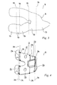
- FIG. 4 is a perspective view of an exemplary distal femoral prosthesis which may be used in an exemplary method of the present disclosure
- FIG. 5 is a perspective view of the prosthesis of FIG. 4 , further illustrating the step of virtually unfolding the prosthesis;
- FIG. 6 is a top view of the two-dimensional outline of the prosthesis of FIG. 4 after the unfolding step of FIG. 5 ;
- FIG. 7 is an illustration of another step of the method of the present disclosure wherein outlines of several exemplary prostheses are compared with outlines of several virtually resected exemplary femurs;
- FIG. 8 is another illustration of the step shown in FIG. 7 .
- the present disclosure may include references to the following terms: anterior (at or near the front of the body, as opposed to the back of the body); posterior (at or near the back of the body, as opposed to the front of the body); lateral (at or near the side of the body, farther from the midsagittal plane, as opposed to medial); medial (at or near the middle of the body, at or near the midsagittal plane, as opposed to lateral); proximal (toward the beginning, at or near the head of the body, as opposed to distal); and distal (further from the beginning, at or near the foot of the body, as opposed to proximal).
- an exemplary method of the present disclosure may be used to determine how a femoral prosthesis will fit on the distal end of a femur, i.e., to assess whether a prosthesis is of the right size and shape for the distal end of the femur and whether the prosthesis suitably conforms thereto.
- the method generally includes the steps of obtaining a three-dimensional (3-D) model of a bone based on an acquired image of the bone, virtually resecting the 3-D model of the bone, i.e., creating or simulating a resection of the bone within a computer or other intelligent processing device, preparing a bone profile of the virtual resection, creating a two-dimensional (2-D) outline or footprint of the resection from the bone profile, preparing an prosthesis profile, creating a 2-D outline or footprint from the prosthesis profile, and comparing the 2-D outlines of the bone profile and the prosthesis profile to assess or determine the fit of the prosthesis with the bone.
- 3-D three-dimensional
- 3-D digital model 10 of an exemplary femur F is illustrated.
- Digital model 10 may be obtained by obtaining a computed tomography ("CT") scan of a femur to produce a 3-D image of the femur and converting the 3-D image to digital model 10.
- CT computed tomography
- the conversion of the 3-D CT scan image to 3-D digital model 10 may be performed using any suitable modeling software including, for example, Amira®, available from Mercury Computer Systems, Inc., of Chelmsford, Massachusetts.
- Digital model 10 may include femur F having distal end F d .
- a virtual resection of distal end F d of model femur F is performed. Similar to the resection performed in actual knee arthroplasty procedures, the virtual resection involves defining femoral cut planes 12a-12e on distal end F d of model femur F. Femoral cut planes 12a-12e are calculated using an algorithm of the software.
- the algorithm calculates femoral cut planes 12a-12e based on a proposed, exemplary femoral prosthesis and the known surgical technique specified for the proposed femoral prosthesis. More particularly, distal end F d of model femur F may be preliminarily measured based on the known surgical technique and using the software described above. The resulting measurements are used to preliminarily select a femoral prosthesis size and type. Resection of distal end F d of model femur F is determined by the selected femoral prosthesis and involves resecting distal end F d of femur F to complement and receive the prosthesis. For example, as shown in FIG. 4 , model femoral prosthesis 20 may be preliminarily selected.
- Femoral prosthesis 20 is a cruciate-retaining femoral prosthetic component having bone engaging surface 22.
- Bone engaging surface 22 includes a plurality of intersecting planar surfaces, including anterior surface 22a, distal surface 22b, posterior surface 22c, anterior chamfer surface 22d, and posterior chamfer surface 22e.
- the virtual resection of distal end F d of model femur F includes defining a plurality of intersecting cut planes 12a-12e including anterior cut plane 12a, distal cut plane 12b, posterior cut plane 12c, anterior chamfer cut plane 12d, and posterior chamfer cut plane 12e, which correspond to the plurality of intersecting planar surfaces 22a-22e of model prosthesis 20 ( FIG. 4 ).
- cut planes 12a-12e intersect one another at femoral cut plane vertices 14a-14d. More particularly, anterior cut plane 12a intersects anterior chamfer cut plane 12d at vertex 14a. Anterior chamfer cut plane 12d intersects distal cut plane 12b at vertex 14b. Distal cut plane 12b intersects posterior chamfer cut plane 12e at vertex 14c. Posterior chamfer cut plane 12e intersects posterior cut plane 12c at vertex 14d.
- femoral profile 16, shown as a dotted line, of the virtually resected model femur F is prepared by outlining cut planes 12a-12e extending between cut plane vertices 14a-14d.
- Two-dimensional outline or footprint 18 of the resected surface of model femur F is then obtained, as shown in FIG. 3 , by unfolding or bending profile 16 at cut plane vertices 14a-14d until cut planes 12a-12e are aligned in a single plane.
- the suitable software mentioned above may be used to manipulate profile 16 to create two-dimensional outline 18.
- model prosthesis 20 includes bone engaging surface 22, which includes anterior planar surface 22a, distal planar surface 22b, posterior planar surface 22c, anterior chamfer planar surface 22d, and posterior chamfer planar surface 22e.
- Planar surfaces 22a-22e intersect one another at prosthesis vertices 24a-24d. More particularly, anterior planar surface 22a intersects anterior chamfer surface 22d at vertex 24a.
- Anterior chamfer surface 22d intersects distal planar surface 22b at vertex 24b.
- Distal planar surface 22b intersects posterior chamfer surface 22e at vertex 24c, and posterior chamfer surface 22e intersects posterior surface 22c at vertex 24d.
- prosthesis profile 25 of model prosthesis 20 is prepared by outlining the perimeter of intersecting planar surfaces 22a-22e between prosthesis vertices 24a-24d.
- Prosthesis profile 25 is represented by the heavy dashed line extending about the perimeter of model prosthesis 20.
- two-dimensional outline or footprint 26 of prosthesis profile 25 is created by using the suitable software to unfold or bend profile 25 at vertices 24a-24d until planar surfaces 22a-22e are aligned within a single plane.
- Prosthesis outline 26 may be visually compared with femur outline 18 to determine and assess whether model prosthesis 20 is a suitable fit for model femur 10.
- Prosthesis outline 26 may be compared with femur outline 18 by superimposing one atop the other and observing the overlapping shapes and the differences therebetween.
- quantitative analysis may be made of outlines 26 and 18. For instance, measurements of outlines 26 and 18 may be taken and the suitable software can calculate deviations between the measurements. For example, width measurements of outlines 26 and 18 at the intersections of each planar surface may be taken and/or at midpoints of each planar surface between such intersections with other planar surfaces.
- Any deviations between outlines 26 and 18 may then be used to calculate proposed changes in prosthesis 20 to thereby reshape prosthesis 20 to minimize the deviations.
- any deviations between outlines 26 and 18 may prompt a user to select a different prosthesis 20 and perform the same analysis to assess the fit of the second prosthesis 20 on model femur 10.
- the method described above has several useful, practical applications.
- the method described above may be used to develop new and improved existing prosthesis designs. It is contemplated that this method may be used to survey a large population of subjects to develop statistics and identify trends in bone shapes, and to adapt prosthesis sizes and shapes accordingly. More specifically, two-dimensional footprints of virtually resected bones of a large population of patients may be obtained and compared to two-dimensional footprints of numerous available prostheses.
- FIGS. 7 and 8 illustrate an exemplary application of the methods of the present disclosure.
- FIG. 7 illustrates femur footprints or outlines 18a-18d, shown as dotted lines, taken from a virtually resected model of a femur of four different subjects compared with footprints or outlines 26a-26c, shown in solid lines, taken from three different models of available prostheses.
- FIG. 8 schematically illustrates the same footprints 18a-18d, 26a-26c. The comparison shown in FIGS. 7 and 8 demonstrates that the prosthesis yielding footprint 26a is larger in width W ( FIG. 6 ) than the virtually resected bones yielding footprints 18b-18d.
- outlines 18a-18d may be used to design or create a prosthesis which substantially matches at least some of outlines 18a-18d.
- a prosthesis may be created or designed which is a best fit approximation to a plurality of outlines 18 which may be based on a specific patient population, such as the female population.
- a method of the present disclosure may be performed on the femurs of a large population of women to obtain medial/lateral and anterior/posterior dimensions of the femurs and calculate ratios between the medial/lateral and anterior/posterior dimensions. These dimensions and calculations may be used in designing femoral components for use on female anatomy. In another exemplary embodiment, a method of the present disclosure may also be used to obtain medial/lateral and anterior/posterior dimensions of existing femoral components and calculate ratios between the medial/lateral and anterior/posterior dimensions of the femoral components.
- the dimensions and calculated ratios may then be used to compare existing femoral components to the dimensions and calculated ratios of the femurs of women to identify potential areas of the femoral component where fit can be optimized. Such a comparison is fully described in U.S. Patent Application Serial No. 11/611,021 , entitled DISTAL FEMORAL KNEE PROSTHESES, assigned to the assignee of the present application.
- the same type of process may be performed for other populations, such as a population of males, various ethnic populations, populations based on age, stature-based populations, and/or populations based on disease progression or disease status.
- the method described above may be used in guiding the design and manufacture of custom prostheses.
- a patient's femur may be modeled, virtually resected and footprinted as described above.
- the footprint could then be used as the footprint for forming a prosthesis.
- the method described above is exemplified with reference to the distal end of the femur and femoral prostheses, the methods of the present invention may be applied to any bone and any prosthesis.
Description
- The present disclosure relates to methods for determining an optimal fit of a prosthesis on a resected bone surface.
- Orthopaedic procedures for the replacement of all, or a portion of, a patient's joint typically require resecting and reshaping of the bones of the joint to receive prosthetic components. For example, a typical total knee prosthesis has three main components: a femoral component for replacing at least a portion of the distal end of the femur, a tibial component for replacing at least a portion of the proximal end of the tibia, and a bearing insert for replacing at least a portion of the articulating tissue between the femur and the tibia. Procedures for implanting a total knee prosthesis typically involve preparing and reshaping both the distal end of the femur and the proximal end of the tibia prior to implanting the prosthetic components. The amount of bone removed may be partially determined by the size and type of prosthetic components to be implanted. The size of prosthetic components may be initially determined by measurements taken of the knee prior to and during surgery, and the final determination of size may be made after taking measurements and trialing a provisional prosthesis during the procedure.
- We are aware of United States Patent No:
5 030 237 , which discloses an elbow prosthesis having a humeral component which substantially replicates the natural trochlear and capitellum convex bearing systems, by using a technique which involves taking parallel sections through cadaveric elbows. It forms the pre-characterising portion of the independent claims. We are also aware ofUS Patent No: 6 510 334 , which discloses a method of producing a knee joint prosthesis based upon a preoperative tomographic image of a damaged knee joint. - According to the invention, we provide a method of designing a prosthesis in accordance with
claim 1 and an apparatus for designing a prosthesis in accordance with claim 4. Optional features are recited in the dependent claims. - The above mentioned and other features of the disclosure, and the manner of attaining them, will become more apparent and will be better understood by reference to the following description of embodiments of the disclosure taken in conjunction with the accompanying drawings, wherein:
-
FIG. 1 is a perspective view of a digital model of the distal end of a femur including a virtual resection according to an exemplary method of the present disclosure; -
FIG. 2 is a perspective view of the digital model ofFIG. 1 , further illustrating the vertices of the virtual resection; -
FIG. 3 is a top view of the two-dimensional outline of the femoral resection ofFIG. 1 ; -
FIG. 4 is a perspective view of an exemplary distal femoral prosthesis which may be used in an exemplary method of the present disclosure; -
FIG. 5 is a perspective view of the prosthesis ofFIG. 4 , further illustrating the step of virtually unfolding the prosthesis; -
FIG. 6 is a top view of the two-dimensional outline of the prosthesis ofFIG. 4 after the unfolding step ofFIG. 5 ; -
FIG. 7 is an illustration of another step of the method of the present disclosure wherein outlines of several exemplary prostheses are compared with outlines of several virtually resected exemplary femurs; and -
FIG. 8 is another illustration of the step shown inFIG. 7 . - Corresponding reference characters indicate corresponding parts throughout the several views. Although the drawings represent embodiments of the present disclosure, the drawings are not necessarily to scale and certain features may be exaggerated in order to better illustrate and explain the present disclosure. Although the exemplifications set out herein illustrate embodiments of the disclosure, the embodiments disclosed below are not intended to be exhaustive or to be construed as limiting the scope of the invention to the precise forms disclosed.
- The present disclosure may include references to the following terms: anterior (at or near the front of the body, as opposed to the back of the body); posterior (at or near the back of the body, as opposed to the front of the body); lateral (at or near the side of the body, farther from the midsagittal plane, as opposed to medial); medial (at or near the middle of the body, at or near the midsagittal plane, as opposed to lateral); proximal (toward the beginning, at or near the head of the body, as opposed to distal); and distal (further from the beginning, at or near the foot of the body, as opposed to proximal).
- Referring to
FIGS. 1-8 , an exemplary method of the present disclosure may be used to determine how a femoral prosthesis will fit on the distal end of a femur, i.e., to assess whether a prosthesis is of the right size and shape for the distal end of the femur and whether the prosthesis suitably conforms thereto. The method generally includes the steps of obtaining a three-dimensional (3-D) model of a bone based on an acquired image of the bone, virtually resecting the 3-D model of the bone, i.e., creating or simulating a resection of the bone within a computer or other intelligent processing device, preparing a bone profile of the virtual resection, creating a two-dimensional (2-D) outline or footprint of the resection from the bone profile, preparing an prosthesis profile, creating a 2-D outline or footprint from the prosthesis profile, and comparing the 2-D outlines of the bone profile and the prosthesis profile to assess or determine the fit of the prosthesis with the bone. - More particularly, referring to
FIG. 1 , 3-Ddigital model 10 of an exemplary femur F is illustrated.Digital model 10 may be obtained by obtaining a computed tomography ("CT") scan of a femur to produce a 3-D image of the femur and converting the 3-D image todigital model 10. The conversion of the 3-D CT scan image to 3-Ddigital model 10 may be performed using any suitable modeling software including, for example, Amira®, available from Mercury Computer Systems, Inc., of Chelmsford, Massachusetts.Digital model 10 may include femur F having distal end Fd. - Referring still to
FIG. 1 , using suitable software, such as MATLAB®, available from The MathWorks, of Natick, Massachusetts, and Unigraphics®, available from UGS Corp., of Plano, Texas, a virtual resection of distal end Fd of model femur F is performed. Similar to the resection performed in actual knee arthroplasty procedures, the virtual resection involves definingfemoral cut planes 12a-12e on distal end Fd of model femur F.Femoral cut planes 12a-12e are calculated using an algorithm of the software. The algorithm calculatesfemoral cut planes 12a-12e based on a proposed, exemplary femoral prosthesis and the known surgical technique specified for the proposed femoral prosthesis. More particularly, distal end Fd of model femur F may be preliminarily measured based on the known surgical technique and using the software described above. The resulting measurements are used to preliminarily select a femoral prosthesis size and type. Resection of distal end Fd of model femur F is determined by the selected femoral prosthesis and involves resecting distal end Fd of femur F to complement and receive the prosthesis. For example, as shown inFIG. 4 , modelfemoral prosthesis 20 may be preliminarily selected.Femoral prosthesis 20 is a cruciate-retaining femoral prosthetic component havingbone engaging surface 22. Boneengaging surface 22 includes a plurality of intersecting planar surfaces, includinganterior surface 22a,distal surface 22b,posterior surface 22c,anterior chamfer surface 22d, andposterior chamfer surface 22e. Accordingly, as shown inFIG. 1 , the virtual resection of distal end Fd of model femur F includes defining a plurality of intersectingcut planes 12a-12e includinganterior cut plane 12a,distal cut plane 12b,posterior cut plane 12c, anteriorchamfer cut plane 12d, and posteriorchamfer cut plane 12e, which correspond to the plurality of intersectingplanar surfaces 22a-22e of model prosthesis 20 (FIG. 4 ). As illustrated inFIGS. 2 and3 , cutplanes 12a-12e intersect one another at femoralcut plane vertices 14a-14d. More particularly,anterior cut plane 12a intersects anteriorchamfer cut plane 12d atvertex 14a. Anteriorchamfer cut plane 12d intersectsdistal cut plane 12b atvertex 14b.Distal cut plane 12b intersects posteriorchamfer cut plane 12e atvertex 14c. Posteriorchamfer cut plane 12e intersectsposterior cut plane 12c atvertex 14d. - Referring still to
FIGS. 1 and 2 ,femoral profile 16, shown as a dotted line, of the virtually resected model femur F is prepared by outliningcut planes 12a-12e extending betweencut plane vertices 14a-14d. Two-dimensional outline orfootprint 18 of the resected surface of model femur F is then obtained, as shown inFIG. 3 , by unfolding orbending profile 16 atcut plane vertices 14a-14d until cutplanes 12a-12e are aligned in a single plane. The suitable software mentioned above may be used to manipulateprofile 16 to create two-dimensional outline 18. - Referring now to
FIGS. 4-6 , two-dimensional outline orfootprint 26 of proposedprosthesis 20 may be made using a process similar to that described above for outline orfootprint 18 offemoral profile 16. More particularly, 3-Ddigital model 20 of a femoral prosthesis may be obtained using any known method and any suitable software, including those described above. As discussed above,model prosthesis 20 includes boneengaging surface 22, which includes anteriorplanar surface 22a, distalplanar surface 22b, posteriorplanar surface 22c, anterior chamferplanar surface 22d, and posterior chamferplanar surface 22e.Planar surfaces 22a-22e intersect one another atprosthesis vertices 24a-24d. More particularly, anteriorplanar surface 22a intersectsanterior chamfer surface 22d atvertex 24a.Anterior chamfer surface 22d intersects distalplanar surface 22b atvertex 24b. Distalplanar surface 22b intersectsposterior chamfer surface 22e atvertex 24c, andposterior chamfer surface 22e intersectsposterior surface 22c atvertex 24d. - Referring to
FIG. 4 ,prosthesis profile 25 ofmodel prosthesis 20 is prepared by outlining the perimeter of intersectingplanar surfaces 22a-22e betweenprosthesis vertices 24a-24d.Prosthesis profile 25 is represented by the heavy dashed line extending about the perimeter ofmodel prosthesis 20. Turning toFIGS. 5 and 6 , two-dimensional outline orfootprint 26 ofprosthesis profile 25 is created by using the suitable software to unfold or bendprofile 25 atvertices 24a-24d untilplanar surfaces 22a-22e are aligned within a single plane. -
Prosthesis outline 26 may be visually compared withfemur outline 18 to determine and assess whethermodel prosthesis 20 is a suitable fit formodel femur 10.Prosthesis outline 26 may be compared withfemur outline 18 by superimposing one atop the other and observing the overlapping shapes and the differences therebetween. Furthermore, using the suitable software mentioned above, quantitative analysis may be made ofoutlines outlines outlines outlines prosthesis 20 to thereby reshapeprosthesis 20 to minimize the deviations. Alternatively, any deviations betweenoutlines different prosthesis 20 and perform the same analysis to assess the fit of thesecond prosthesis 20 onmodel femur 10. - The method described above has several useful, practical applications. For example, the method described above may be used to develop new and improved existing prosthesis designs. It is contemplated that this method may be used to survey a large population of subjects to develop statistics and identify trends in bone shapes, and to adapt prosthesis sizes and shapes accordingly. More specifically, two-dimensional footprints of virtually resected bones of a large population of patients may be obtained and compared to two-dimensional footprints of numerous available prostheses.
-
FIGS. 7 and 8 illustrate an exemplary application of the methods of the present disclosure.FIG. 7 illustrates femur footprints or outlines 18a-18d, shown as dotted lines, taken from a virtually resected model of a femur of four different subjects compared with footprints or outlines 26a-26c, shown in solid lines, taken from three different models of available prostheses.FIG. 8 schematically illustrates thesame footprints 18a-18d, 26a-26c. The comparison shown inFIGS. 7 and 8 demonstrates that theprosthesis yielding footprint 26a is larger in width W (FIG. 6 ) than the virtually resectedbones yielding footprints 18b-18d. In an exemplary embodiment, outlines 18a-18d may be used to design or create a prosthesis which substantially matches at least some ofoutlines 18a-18d. For example, a prosthesis may be created or designed which is a best fit approximation to a plurality ofoutlines 18 which may be based on a specific patient population, such as the female population. - In an exemplary embodiment, a method of the present disclosure may be performed on the femurs of a large population of women to obtain medial/lateral and anterior/posterior dimensions of the femurs and calculate ratios between the medial/lateral and anterior/posterior dimensions. These dimensions and calculations may be used in designing femoral components for use on female anatomy. In another exemplary embodiment, a method of the present disclosure may also be used to obtain medial/lateral and anterior/posterior dimensions of existing femoral components and calculate ratios between the medial/lateral and anterior/posterior dimensions of the femoral components. The dimensions and calculated ratios may then be used to compare existing femoral components to the dimensions and calculated ratios of the femurs of women to identify potential areas of the femoral component where fit can be optimized. Such a comparison is fully described in
U.S. Patent Application Serial No. 11/611,021 , entitled DISTAL FEMORAL KNEE PROSTHESES, assigned to the assignee of the present application. The same type of process may be performed for other populations, such as a population of males, various ethnic populations, populations based on age, stature-based populations, and/or populations based on disease progression or disease status. - In addition, the method described above may be used in guiding the design and manufacture of custom prostheses. For instance, a patient's femur may be modeled, virtually resected and footprinted as described above. The footprint could then be used as the footprint for forming a prosthesis. Although the method described above is exemplified with reference to the distal end of the femur and femoral prostheses, the methods of the present invention may be applied to any bone and any prosthesis.
- While this invention has been described as having exemplary designs, it may be further modified within the scope of the claims.
Claims (5)
- A method of designing a prosthesis to substantially fit a resected bone surface (12) based on a population of bones, the method characterised in that the resected bore surface consists of a plurality of intersecting cut plane, wherein the method comprises the steps of:
creating a plurality of two-dimensional outlines (18) corresponding to each of the cut planes of the resected bone surface for each bone of the population; and
determining a contour (25) of a bone engaging surface (22) of a prosthesis (20) using the plurality of two-dimensional outlines, wherein the contour substantially matches the plurality of two-dimensional outlines of the resected bone surfaces. - The method of claim 1, wherein said using step comprises the step of determining the contour of the bone engaging surface of the prosthesis using a best fit approximation of the plurality of two-dimensional outlines of the resected bone surfaces.
- The method of claims 1 or 2, wherein said said creating step comprises the steps of:obtaining a three-dimensional contour (10) of each resected bone surface;identifying a vertex (14) between a first planar surface (12) of each resected bone surface and a second planar surface (12) of each resected bone surface;manipulating the first planar surface to be coplanar with the second planar surface; andoutlining a perimeter (16) of the first planar surface and the second planar surface to define the two-dimensional outline for each resected bone surface.
- An apparatus for designing a prosthesis to substantially fit a resected bone surface (12) based on a population of bones characterised in that the resected bore surface consists of a plurality of intersecting cut plane, wherein the apparatus comprises:a first computer configured to create a plurality of two-dimensional outlines (18) corresponding to each of the cut planes of resected bone surface for each bone of the population; anda second computer configured to determine a contour (25) of a bone engaging surface (22) of a prosthesis (20) which substantially matches the plurality of two-dimensional outlines of the resected bone surfaces.
- The apparatus of claim 4, wherein said first computer comprises:a process configured to identify a vertex (14) between a first planar surface (12) of the resected bone surface and a second planar surface (12) of the resected bone surface based on a three-dimensional contour (10) of the resected bone surface;wherein said first computer is configured to manipulate the first planar surface to be coplanar with the second planar surface and to outline a perimeter (16) of the first planar surface and the second planar surface to define the two-dimensional outline for each resected bone surface.
Applications Claiming Priority (2)
| Application Number | Priority Date | Filing Date | Title |
|---|---|---|---|
| US78363006P | 2006-03-17 | 2006-03-17 | |
| PCT/US2007/063949 WO2007109467A1 (en) | 2006-03-17 | 2007-03-14 | Methods of predetermining the contour of a resected bone surface and assessing the fit of a prosthesis on the bone |
Publications (2)
| Publication Number | Publication Date |
|---|---|
| EP2001411A1 EP2001411A1 (en) | 2008-12-17 |
| EP2001411B1 true EP2001411B1 (en) | 2013-05-01 |
Family
ID=38197833
Family Applications (1)
| Application Number | Title | Priority Date | Filing Date |
|---|---|---|---|
| EP07758498.5A Not-in-force EP2001411B1 (en) | 2006-03-17 | 2007-03-14 | Methods of predetermining the contour of a resected bone surface and assessing the fit of a prosthesis on the bone |
Country Status (6)
| Country | Link |
|---|---|
| US (3) | US8231634B2 (en) |
| EP (1) | EP2001411B1 (en) |
| JP (1) | JP5407014B2 (en) |
| AU (1) | AU2007227129B2 (en) |
| CA (1) | CA2644574C (en) |
| WO (1) | WO2007109467A1 (en) |
Cited By (1)
| Publication number | Priority date | Publication date | Assignee | Title |
|---|---|---|---|---|
| US9504579B2 (en) | 2006-03-17 | 2016-11-29 | Zimmer, Inc. | Methods of predetermining the contour of a resected bone surface and assessing the fit of a prosthesis on the bone |
Families Citing this family (142)
| Publication number | Priority date | Publication date | Assignee | Title |
|---|---|---|---|---|
| US8882847B2 (en) | 2001-05-25 | 2014-11-11 | Conformis, Inc. | Patient selectable knee joint arthroplasty devices |
| US7468075B2 (en) | 2001-05-25 | 2008-12-23 | Conformis, Inc. | Methods and compositions for articular repair |
| US7534263B2 (en) | 2001-05-25 | 2009-05-19 | Conformis, Inc. | Surgical tools facilitating increased accuracy, speed and simplicity in performing joint arthroplasty |
| US8771365B2 (en) | 2009-02-25 | 2014-07-08 | Conformis, Inc. | Patient-adapted and improved orthopedic implants, designs, and related tools |
| US8480754B2 (en) | 2001-05-25 | 2013-07-09 | Conformis, Inc. | Patient-adapted and improved articular implants, designs and related guide tools |
| US8735773B2 (en) | 2007-02-14 | 2014-05-27 | Conformis, Inc. | Implant device and method for manufacture |
| US8545569B2 (en) | 2001-05-25 | 2013-10-01 | Conformis, Inc. | Patient selectable knee arthroplasty devices |
| US8083745B2 (en) | 2001-05-25 | 2011-12-27 | Conformis, Inc. | Surgical tools for arthroplasty |
| US9603711B2 (en) | 2001-05-25 | 2017-03-28 | Conformis, Inc. | Patient-adapted and improved articular implants, designs and related guide tools |
| US8556983B2 (en) | 2001-05-25 | 2013-10-15 | Conformis, Inc. | Patient-adapted and improved orthopedic implants, designs and related tools |
| US8617242B2 (en) | 2001-05-25 | 2013-12-31 | Conformis, Inc. | Implant device and method for manufacture |
| DE60239674D1 (en) | 2001-05-25 | 2011-05-19 | Conformis Inc | METHOD AND COMPOSITIONS FOR REPAIRING THE SURFACE OF JOINTS |
| US9308091B2 (en) | 2001-05-25 | 2016-04-12 | Conformis, Inc. | Devices and methods for treatment of facet and other joints |
| US8439926B2 (en) | 2001-05-25 | 2013-05-14 | Conformis, Inc. | Patient selectable joint arthroplasty devices and surgical tools |
| JP2006501977A (en) | 2002-10-07 | 2006-01-19 | コンフォーミス・インコーポレイテッド | Minimally invasive joint implant with a three-dimensional profile that conforms to the joint surface |
| US7796791B2 (en) | 2002-11-07 | 2010-09-14 | Conformis, Inc. | Methods for determining meniscal size and shape and for devising treatment |
| US20070066917A1 (en) * | 2005-09-20 | 2007-03-22 | Hodorek Robert A | Method for simulating prosthetic implant selection and placement |
| US20070156066A1 (en) * | 2006-01-03 | 2007-07-05 | Zimmer Technology, Inc. | Device for determining the shape of an anatomic surface |
| US8623026B2 (en) | 2006-02-06 | 2014-01-07 | Conformis, Inc. | Patient selectable joint arthroplasty devices and surgical tools incorporating anatomical relief |
| AU2007212033B2 (en) | 2006-02-06 | 2014-01-23 | Conformis, Inc. | Patient selectable joint arthroplasty devices and surgical tools |
| EP2007291A2 (en) | 2006-02-15 | 2008-12-31 | Otismed Corp. | Arthroplasty jigs and related methods |
| US9808262B2 (en) | 2006-02-15 | 2017-11-07 | Howmedica Osteonics Corporation | Arthroplasty devices and related methods |
| US8608748B2 (en) | 2006-02-27 | 2013-12-17 | Biomet Manufacturing, Llc | Patient specific guides |
| US9113971B2 (en) | 2006-02-27 | 2015-08-25 | Biomet Manufacturing, Llc | Femoral acetabular impingement guide |
| US8473305B2 (en) | 2007-04-17 | 2013-06-25 | Biomet Manufacturing Corp. | Method and apparatus for manufacturing an implant |
| US8282646B2 (en) | 2006-02-27 | 2012-10-09 | Biomet Manufacturing Corp. | Patient specific knee alignment guide and associated method |
| US8377066B2 (en) | 2006-02-27 | 2013-02-19 | Biomet Manufacturing Corp. | Patient-specific elbow guides and associated methods |
| US8535387B2 (en) | 2006-02-27 | 2013-09-17 | Biomet Manufacturing, Llc | Patient-specific tools and implants |
| US9339278B2 (en) | 2006-02-27 | 2016-05-17 | Biomet Manufacturing, Llc | Patient-specific acetabular guides and associated instruments |
| US8591516B2 (en) | 2006-02-27 | 2013-11-26 | Biomet Manufacturing, Llc | Patient-specific orthopedic instruments |
| US9173661B2 (en) | 2006-02-27 | 2015-11-03 | Biomet Manufacturing, Llc | Patient specific alignment guide with cutting surface and laser indicator |
| US8407067B2 (en) | 2007-04-17 | 2013-03-26 | Biomet Manufacturing Corp. | Method and apparatus for manufacturing an implant |
| US8858561B2 (en) | 2006-06-09 | 2014-10-14 | Blomet Manufacturing, LLC | Patient-specific alignment guide |
| US8241293B2 (en) | 2006-02-27 | 2012-08-14 | Biomet Manufacturing Corp. | Patient specific high tibia osteotomy |
| US10278711B2 (en) | 2006-02-27 | 2019-05-07 | Biomet Manufacturing, Llc | Patient-specific femoral guide |
| US20150335438A1 (en) | 2006-02-27 | 2015-11-26 | Biomet Manufacturing, Llc. | Patient-specific augments |
| US9289253B2 (en) | 2006-02-27 | 2016-03-22 | Biomet Manufacturing, Llc | Patient-specific shoulder guide |
| US8603180B2 (en) | 2006-02-27 | 2013-12-10 | Biomet Manufacturing, Llc | Patient-specific acetabular alignment guides |
| US8070752B2 (en) | 2006-02-27 | 2011-12-06 | Biomet Manufacturing Corp. | Patient specific alignment guide and inter-operative adjustment |
| US8298237B2 (en) | 2006-06-09 | 2012-10-30 | Biomet Manufacturing Corp. | Patient-specific alignment guide for multiple incisions |
| US9345548B2 (en) | 2006-02-27 | 2016-05-24 | Biomet Manufacturing, Llc | Patient-specific pre-operative planning |
| US7967868B2 (en) | 2007-04-17 | 2011-06-28 | Biomet Manufacturing Corp. | Patient-modified implant and associated method |
| US8608749B2 (en) | 2006-02-27 | 2013-12-17 | Biomet Manufacturing, Llc | Patient-specific acetabular guides and associated instruments |
| US9918740B2 (en) | 2006-02-27 | 2018-03-20 | Biomet Manufacturing, Llc | Backup surgical instrument system and method |
| US8864769B2 (en) | 2006-02-27 | 2014-10-21 | Biomet Manufacturing, Llc | Alignment guides with patient-specific anchoring elements |
| US8568487B2 (en) | 2006-02-27 | 2013-10-29 | Biomet Manufacturing, Llc | Patient-specific hip joint devices |
| US8133234B2 (en) | 2006-02-27 | 2012-03-13 | Biomet Manufacturing Corp. | Patient specific acetabular guide and method |
| US9907659B2 (en) | 2007-04-17 | 2018-03-06 | Biomet Manufacturing, Llc | Method and apparatus for manufacturing an implant |
| US8092465B2 (en) | 2006-06-09 | 2012-01-10 | Biomet Manufacturing Corp. | Patient specific knee alignment guide and associated method |
| US9795399B2 (en) | 2006-06-09 | 2017-10-24 | Biomet Manufacturing, Llc | Patient-specific knee alignment guide and associated method |
| US8460302B2 (en) | 2006-12-18 | 2013-06-11 | Otismed Corporation | Arthroplasty devices and related methods |
| WO2008157412A2 (en) | 2007-06-13 | 2008-12-24 | Conformis, Inc. | Surgical cutting guide |
| US9179983B2 (en) | 2007-08-14 | 2015-11-10 | Zimmer, Inc. | Method of determining a contour of an anatomical structure and selecting an orthopaedic implant to replicate the anatomical structure |
| CA2882265C (en) * | 2007-08-17 | 2017-01-03 | Zimmer, Inc. | Implant design analysis suite |
| US8265949B2 (en) | 2007-09-27 | 2012-09-11 | Depuy Products, Inc. | Customized patient surgical plan |
| CN102652687B (en) | 2007-09-30 | 2015-08-19 | 德普伊产品公司 | The patient-specific orthopaedic surgical instrumentation of customization |
| US8357111B2 (en) | 2007-09-30 | 2013-01-22 | Depuy Products, Inc. | Method and system for designing patient-specific orthopaedic surgical instruments |
| USD642263S1 (en) | 2007-10-25 | 2011-07-26 | Otismed Corporation | Arthroplasty jig blank |
| US8460303B2 (en) | 2007-10-25 | 2013-06-11 | Otismed Corporation | Arthroplasty systems and devices, and related methods |
| US10582934B2 (en) | 2007-11-27 | 2020-03-10 | Howmedica Osteonics Corporation | Generating MRI images usable for the creation of 3D bone models employed to make customized arthroplasty jigs |
| US8480679B2 (en) | 2008-04-29 | 2013-07-09 | Otismed Corporation | Generation of a computerized bone model representative of a pre-degenerated state and useable in the design and manufacture of arthroplasty devices |
| US8715291B2 (en) | 2007-12-18 | 2014-05-06 | Otismed Corporation | Arthroplasty system and related methods |
| US8737700B2 (en) | 2007-12-18 | 2014-05-27 | Otismed Corporation | Preoperatively planning an arthroplasty procedure and generating a corresponding patient specific arthroplasty resection guide |
| US8160345B2 (en) | 2008-04-30 | 2012-04-17 | Otismed Corporation | System and method for image segmentation in generating computer models of a joint to undergo arthroplasty |
| US8311306B2 (en) | 2008-04-30 | 2012-11-13 | Otismed Corporation | System and method for image segmentation in generating computer models of a joint to undergo arthroplasty |
| US8545509B2 (en) | 2007-12-18 | 2013-10-01 | Otismed Corporation | Arthroplasty system and related methods |
| US8617171B2 (en) | 2007-12-18 | 2013-12-31 | Otismed Corporation | Preoperatively planning an arthroplasty procedure and generating a corresponding patient specific arthroplasty resection guide |
| US8777875B2 (en) | 2008-07-23 | 2014-07-15 | Otismed Corporation | System and method for manufacturing arthroplasty jigs having improved mating accuracy |
| US8221430B2 (en) | 2007-12-18 | 2012-07-17 | Otismed Corporation | System and method for manufacturing arthroplasty jigs |
| US8734455B2 (en) | 2008-02-29 | 2014-05-27 | Otismed Corporation | Hip resurfacing surgical guide tool |
| WO2009111626A2 (en) | 2008-03-05 | 2009-09-11 | Conformis, Inc. | Implants for altering wear patterns of articular surfaces |
| US8617175B2 (en) | 2008-12-16 | 2013-12-31 | Otismed Corporation | Unicompartmental customized arthroplasty cutting jigs and methods of making the same |
| US8170641B2 (en) | 2009-02-20 | 2012-05-01 | Biomet Manufacturing Corp. | Method of imaging an extremity of a patient |
| WO2010099231A2 (en) | 2009-02-24 | 2010-09-02 | Conformis, Inc. | Automated systems for manufacturing patient-specific orthopedic implants and instrumentation |
| SG10201400158UA (en) | 2009-02-25 | 2014-04-28 | Conformis Inc | Patient-adapted and improved orthopedic implants, designs and related tools |
| CA2753488C (en) | 2009-02-25 | 2014-04-29 | Mohamed Rashwan Mahfouz | Customized orthopaedic implants and related methods |
| US9078755B2 (en) * | 2009-02-25 | 2015-07-14 | Zimmer, Inc. | Ethnic-specific orthopaedic implants and custom cutting jigs |
| SG175229A1 (en) | 2009-04-16 | 2011-11-28 | Conformis Inc | Patient-specific joint arthroplasty devices for ligament repair |
| US8876830B2 (en) * | 2009-08-13 | 2014-11-04 | Zimmer, Inc. | Virtual implant placement in the OR |
| DE102009028503B4 (en) | 2009-08-13 | 2013-11-14 | Biomet Manufacturing Corp. | Resection template for the resection of bones, method for producing such a resection template and operation set for performing knee joint surgery |
| EP2509539B1 (en) | 2009-12-11 | 2020-07-01 | ConforMIS, Inc. | Patient-specific and patient-engineered orthopedic implants |
| US8652148B2 (en) * | 2010-02-25 | 2014-02-18 | Zimmer, Inc. | Tracked cartilage repair system |
| US8632547B2 (en) | 2010-02-26 | 2014-01-21 | Biomet Sports Medicine, Llc | Patient-specific osteotomy devices and methods |
| US9066727B2 (en) | 2010-03-04 | 2015-06-30 | Materialise Nv | Patient-specific computed tomography guides |
| US9375303B1 (en) | 2010-04-15 | 2016-06-28 | Zimmer, Inc. | Methods of ordering and manufacturing orthopedic components |
| WO2012021895A2 (en) * | 2010-08-13 | 2012-02-16 | Smith & Nephew, Inc. | Systems and methods for optimizing parameters of orthopaedic procedures |
| US9271744B2 (en) | 2010-09-29 | 2016-03-01 | Biomet Manufacturing, Llc | Patient-specific guide for partial acetabular socket replacement |
| US9968376B2 (en) | 2010-11-29 | 2018-05-15 | Biomet Manufacturing, Llc | Patient-specific orthopedic instruments |
| SG193484A1 (en) | 2011-02-15 | 2013-10-30 | Conformis Inc | Patent-adapted and improved articular implants, designs, surgical procedures and related guide tools |
| US9241745B2 (en) | 2011-03-07 | 2016-01-26 | Biomet Manufacturing, Llc | Patient-specific femoral version guide |
| US8715289B2 (en) | 2011-04-15 | 2014-05-06 | Biomet Manufacturing, Llc | Patient-specific numerically controlled instrument |
| US9675400B2 (en) | 2011-04-19 | 2017-06-13 | Biomet Manufacturing, Llc | Patient-specific fracture fixation instrumentation and method |
| US8668700B2 (en) | 2011-04-29 | 2014-03-11 | Biomet Manufacturing, Llc | Patient-specific convertible guides |
| US8956364B2 (en) | 2011-04-29 | 2015-02-17 | Biomet Manufacturing, Llc | Patient-specific partial knee guides and other instruments |
| US8532807B2 (en) | 2011-06-06 | 2013-09-10 | Biomet Manufacturing, Llc | Pre-operative planning and manufacturing method for orthopedic procedure |
| US9084618B2 (en) | 2011-06-13 | 2015-07-21 | Biomet Manufacturing, Llc | Drill guides for confirming alignment of patient-specific alignment guides |
| US20130001121A1 (en) | 2011-07-01 | 2013-01-03 | Biomet Manufacturing Corp. | Backup kit for a patient-specific arthroplasty kit assembly |
| US8764760B2 (en) | 2011-07-01 | 2014-07-01 | Biomet Manufacturing, Llc | Patient-specific bone-cutting guidance instruments and methods |
| MX2014000752A (en) | 2011-07-20 | 2014-11-13 | Smith & Nephew Inc | Systems and methods for optimizing fit of an implant to anatomy. |
| US8597365B2 (en) | 2011-08-04 | 2013-12-03 | Biomet Manufacturing, Llc | Patient-specific pelvic implants for acetabular reconstruction |
| US9066734B2 (en) | 2011-08-31 | 2015-06-30 | Biomet Manufacturing, Llc | Patient-specific sacroiliac guides and associated methods |
| US9295497B2 (en) | 2011-08-31 | 2016-03-29 | Biomet Manufacturing, Llc | Patient-specific sacroiliac and pedicle guides |
| US9386993B2 (en) | 2011-09-29 | 2016-07-12 | Biomet Manufacturing, Llc | Patient-specific femoroacetabular impingement instruments and methods |
| US9451973B2 (en) | 2011-10-27 | 2016-09-27 | Biomet Manufacturing, Llc | Patient specific glenoid guide |
| US9301812B2 (en) | 2011-10-27 | 2016-04-05 | Biomet Manufacturing, Llc | Methods for patient-specific shoulder arthroplasty |
| US9554910B2 (en) | 2011-10-27 | 2017-01-31 | Biomet Manufacturing, Llc | Patient-specific glenoid guide and implants |
| KR20130046336A (en) | 2011-10-27 | 2013-05-07 | 삼성전자주식회사 | Multi-view device of display apparatus and contol method thereof, and display system |
| ES2635542T3 (en) | 2011-10-27 | 2017-10-04 | Biomet Manufacturing, Llc | Glenoid guides specific to the patient |
| US9408686B1 (en) | 2012-01-20 | 2016-08-09 | Conformis, Inc. | Devices, systems and methods for manufacturing orthopedic implants |
| US9237950B2 (en) | 2012-02-02 | 2016-01-19 | Biomet Manufacturing, Llc | Implant with patient-specific porous structure |
| WO2014036551A1 (en) | 2012-08-31 | 2014-03-06 | Smith & Nephew, Inc. | Patient specific implant technology |
| US9402637B2 (en) | 2012-10-11 | 2016-08-02 | Howmedica Osteonics Corporation | Customized arthroplasty cutting guides and surgical methods using the same |
| US9204977B2 (en) | 2012-12-11 | 2015-12-08 | Biomet Manufacturing, Llc | Patient-specific acetabular guide for anterior approach |
| US9060788B2 (en) | 2012-12-11 | 2015-06-23 | Biomet Manufacturing, Llc | Patient-specific acetabular guide for anterior approach |
| US9387083B2 (en) | 2013-01-30 | 2016-07-12 | Conformis, Inc. | Acquiring and utilizing kinematic information for patient-adapted implants, tools and surgical procedures |
| US9839438B2 (en) | 2013-03-11 | 2017-12-12 | Biomet Manufacturing, Llc | Patient-specific glenoid guide with a reusable guide holder |
| US9579107B2 (en) | 2013-03-12 | 2017-02-28 | Biomet Manufacturing, Llc | Multi-point fit for patient specific guide |
| US9498233B2 (en) | 2013-03-13 | 2016-11-22 | Biomet Manufacturing, Llc. | Universal acetabular guide and associated hardware |
| US9826981B2 (en) | 2013-03-13 | 2017-11-28 | Biomet Manufacturing, Llc | Tangential fit of patient-specific guides |
| US9517145B2 (en) | 2013-03-15 | 2016-12-13 | Biomet Manufacturing, Llc | Guide alignment system and method |
| US10467752B2 (en) * | 2013-06-11 | 2019-11-05 | Atsushi Tanji | Bone cutting support system, information processing apparatus, image processing method, and image processing program |
| US10166109B2 (en) | 2013-09-18 | 2019-01-01 | Stryker Corporation | Patient specific bone preparation for consistent effective fixation feature engagement |
| US20150112349A1 (en) | 2013-10-21 | 2015-04-23 | Biomet Manufacturing, Llc | Ligament Guide Registration |
| US10282488B2 (en) | 2014-04-25 | 2019-05-07 | Biomet Manufacturing, Llc | HTO guide with optional guided ACL/PCL tunnels |
| US9408616B2 (en) | 2014-05-12 | 2016-08-09 | Biomet Manufacturing, Llc | Humeral cut guide |
| US9839436B2 (en) | 2014-06-03 | 2017-12-12 | Biomet Manufacturing, Llc | Patient-specific glenoid depth control |
| US9561040B2 (en) | 2014-06-03 | 2017-02-07 | Biomet Manufacturing, Llc | Patient-specific glenoid depth control |
| US9833245B2 (en) | 2014-09-29 | 2017-12-05 | Biomet Sports Medicine, Llc | Tibial tubercule osteotomy |
| US9826994B2 (en) | 2014-09-29 | 2017-11-28 | Biomet Manufacturing, Llc | Adjustable glenoid pin insertion guide |
| US9820868B2 (en) | 2015-03-30 | 2017-11-21 | Biomet Manufacturing, Llc | Method and apparatus for a pin apparatus |
| US10568647B2 (en) | 2015-06-25 | 2020-02-25 | Biomet Manufacturing, Llc | Patient-specific humeral guide designs |
| US10226262B2 (en) | 2015-06-25 | 2019-03-12 | Biomet Manufacturing, Llc | Patient-specific humeral guide designs |
| US10357315B2 (en) * | 2016-05-27 | 2019-07-23 | Mako Surgical Corp. | Preoperative planning and associated intraoperative registration for a surgical system |
| CN109788997B (en) * | 2016-09-27 | 2021-07-13 | 登士柏种植体有限公司 | Force-closed or shape-closed positioning of a surgical template for a guided dental implant |
| US10722310B2 (en) | 2017-03-13 | 2020-07-28 | Zimmer Biomet CMF and Thoracic, LLC | Virtual surgery planning system and method |
| WO2019175901A1 (en) * | 2018-03-16 | 2019-09-19 | Prayasta 3D Inventions Pvt Ltd | System and method of manufacturing prostheses |
| US11051829B2 (en) | 2018-06-26 | 2021-07-06 | DePuy Synthes Products, Inc. | Customized patient-specific orthopaedic surgical instrument |
| US10684295B2 (en) | 2018-07-05 | 2020-06-16 | VistaPath Biosystems Inc. | Apparatus and methods for processing and cataloging of samples |
| US10925746B2 (en) * | 2018-07-25 | 2021-02-23 | Orthopedix, Inc. | Patient specific carpal implant |
| US10918487B2 (en) * | 2018-07-25 | 2021-02-16 | Orthopedix, Inc. | Prosthetic implant caps |
| US11793574B2 (en) | 2020-03-16 | 2023-10-24 | Stryker Australia Pty Ltd | Automated cut planning for removal of diseased regions |
| CN114073606B (en) * | 2022-01-07 | 2022-05-17 | 北京威高智慧科技有限公司 | Simulation bone cutting system |
Family Cites Families (91)
| Publication number | Priority date | Publication date | Assignee | Title |
|---|---|---|---|---|
| DE2821247A1 (en) | 1978-05-16 | 1979-11-22 | Precitec Gmbh | Three=dimensional foot sole measuring device - has spring loaded pins in grid pattern in tread surface to follow foot contour |
| US5030237A (en) * | 1983-06-24 | 1991-07-09 | Queen's University At Kingston | Elbow prosthesis |
| US4549540A (en) * | 1983-11-16 | 1985-10-29 | Precision Surgical Instruments, Inc. | Thigh restraining apparatus and method |
| US4936862A (en) * | 1986-05-30 | 1990-06-26 | Walker Peter S | Method of designing and manufacturing a human joint prosthesis |
| US4979949A (en) * | 1988-04-26 | 1990-12-25 | The Board Of Regents Of The University Of Washington | Robot-aided system for surgery |
| US4913413A (en) * | 1989-06-09 | 1990-04-03 | Faro Medical Technologies Inc. | Universal leg holder |
| US5086401A (en) * | 1990-05-11 | 1992-02-04 | International Business Machines Corporation | Image-directed robotic system for precise robotic surgery including redundant consistency checking |
| US6006126A (en) * | 1991-01-28 | 1999-12-21 | Cosman; Eric R. | System and method for stereotactic registration of image scan data |
| GB9307105D0 (en) | 1993-04-05 | 1993-05-26 | Univ London | Three-dimensional profile guage |
| GB9405299D0 (en) * | 1994-03-17 | 1994-04-27 | Roke Manor Research | Improvements in or relating to video-based systems for computer assisted surgery and localisation |
| DE29521895U1 (en) * | 1994-10-07 | 1998-09-10 | Univ St Louis | Surgical navigation system comprising reference and localization frames |
| US5540696A (en) * | 1995-01-06 | 1996-07-30 | Zimmer, Inc. | Instrumentation for use in orthopaedic surgery |
| US5828813A (en) * | 1995-09-07 | 1998-10-27 | California Institute Of Technology | Six axis force feedback input device |
| US5682886A (en) * | 1995-12-26 | 1997-11-04 | Musculographics Inc | Computer-assisted surgical system |
| US8882847B2 (en) * | 2001-05-25 | 2014-11-11 | Conformis, Inc. | Patient selectable knee joint arthroplasty devices |
| US8545569B2 (en) * | 2001-05-25 | 2013-10-01 | Conformis, Inc. | Patient selectable knee arthroplasty devices |
| US7618451B2 (en) * | 2001-05-25 | 2009-11-17 | Conformis, Inc. | Patient selectable joint arthroplasty devices and surgical tools facilitating increased accuracy, speed and simplicity in performing total and partial joint arthroplasty |
| US6205411B1 (en) * | 1997-02-21 | 2001-03-20 | Carnegie Mellon University | Computer-assisted surgery planner and intra-operative guidance system |
| US5921992A (en) * | 1997-04-11 | 1999-07-13 | Radionics, Inc. | Method and system for frameless tool calibration |
| US5834759A (en) * | 1997-05-22 | 1998-11-10 | Glossop; Neil David | Tracking device having emitter groups with different emitting directions |
| US6434507B1 (en) * | 1997-09-05 | 2002-08-13 | Surgical Navigation Technologies, Inc. | Medical instrument and method for use with computer-assisted image guided surgery |
| US6096050A (en) * | 1997-09-19 | 2000-08-01 | Surgical Navigation Specialist Inc. | Method and apparatus for correlating a body with an image of the body |
| US6348058B1 (en) * | 1997-12-12 | 2002-02-19 | Surgical Navigation Technologies, Inc. | Image guided spinal surgery guide, system, and method for use thereof |
| WO1999037220A1 (en) | 1998-01-23 | 1999-07-29 | Sm Scienzia Machinale S.R.L. | Orthopaedic surgery apparatus for guiding a tool and for supporting a limb |
| US6197017B1 (en) * | 1998-02-24 | 2001-03-06 | Brock Rogers Surgical, Inc. | Articulated apparatus for telemanipulator system |
| FR2776176B1 (en) | 1998-03-20 | 2000-08-18 | Aesculap Sa | SYSTEM FOR POSITIONING A BONE CUTTING GUIDE FOR THE PREPARATION FOR LAYING A KNEE PROSTHESIS |
| US6233504B1 (en) * | 1998-04-16 | 2001-05-15 | California Institute Of Technology | Tool actuation and force feedback on robot-assisted microsurgery system |
| FR2777441B1 (en) * | 1998-04-21 | 2000-09-15 | Kreon Ind | SYSTEM FOR REVEALING A THREE-DIMENSIONAL SHAPE, IN PARTICULAR A PLANT VOUCH, AND METHOD FOR MAKING A SHOE OR AN ORTHOPEDIC SOLE IMPLEMENTING THE SYSTEM |
| AU3924599A (en) * | 1998-05-28 | 1999-12-13 | Orthosoft, Inc. | Interactive computer-assisted surgical system and method thereof |
| WO2000003210A1 (en) | 1998-07-10 | 2000-01-20 | Sugen, Inc. | Device for estimating volume |
| US6430434B1 (en) * | 1998-12-14 | 2002-08-06 | Integrated Surgical Systems, Inc. | Method for determining the location and orientation of a bone for computer-assisted orthopedic procedures using intraoperatively attached markers |
| US6285902B1 (en) * | 1999-02-10 | 2001-09-04 | Surgical Insights, Inc. | Computer assisted targeting device for use in orthopaedic surgery |
| US6470207B1 (en) * | 1999-03-23 | 2002-10-22 | Surgical Navigation Technologies, Inc. | Navigational guidance via computer-assisted fluoroscopic imaging |
| US6491699B1 (en) * | 1999-04-20 | 2002-12-10 | Surgical Navigation Technologies, Inc. | Instrument guidance method and system for image guided surgery |
| DE19922279A1 (en) * | 1999-05-11 | 2000-11-16 | Friedrich Schiller Uni Jena Bu | Procedure for generating patient-specific implants |
| US6338716B1 (en) * | 1999-11-24 | 2002-01-15 | Acuson Corporation | Medical diagnostic ultrasonic transducer probe and imaging system for use with a position and orientation sensor |
| US7234937B2 (en) * | 1999-11-30 | 2007-06-26 | Orametrix, Inc. | Unified workstation for virtual craniofacial diagnosis, treatment planning and therapeutics |
| CA2402326A1 (en) * | 2000-03-10 | 2001-09-13 | Smith & Nephew, Inc. | Apparatus for use in arthroplasty of the knees |
| US6772026B2 (en) * | 2000-04-05 | 2004-08-03 | Therics, Inc. | System and method for rapidly customizing design, manufacture and/or selection of biomedical devices |
| US6701174B1 (en) * | 2000-04-07 | 2004-03-02 | Carnegie Mellon University | Computer-aided bone distraction |
| US6484049B1 (en) * | 2000-04-28 | 2002-11-19 | Ge Medical Systems Global Technology Company, Llc | Fluoroscopic tracking and visualization system |
| DE60109541T2 (en) * | 2000-09-18 | 2006-02-16 | Fuji Photo Film Co., Ltd., Minami-Ashigara | System for selecting, displaying and storing artificial bone templates and record carriers therefor |
| EP1190676B1 (en) * | 2000-09-26 | 2003-08-13 | BrainLAB AG | Device for determining the position of a cutting guide |
| US6510334B1 (en) | 2000-11-14 | 2003-01-21 | Luis Schuster | Method of producing an endoprosthesis as a joint substitute for a knee joint |
| WO2002061688A2 (en) * | 2001-01-29 | 2002-08-08 | The Acrobot Company Limited | Modelling for surgery |
| US7547307B2 (en) | 2001-02-27 | 2009-06-16 | Smith & Nephew, Inc. | Computer assisted knee arthroplasty instrumentation, systems, and processes |
| US20030018457A1 (en) * | 2001-03-13 | 2003-01-23 | Lett Gregory Scott | Biological modeling utilizing image data |
| US7526112B2 (en) * | 2001-04-30 | 2009-04-28 | Chase Medical, L.P. | System and method for facilitating cardiac intervention |
| US7242999B2 (en) * | 2001-05-11 | 2007-07-10 | Kenneth Kuk-Kei Wang | Method and apparatus for identifying virtual body profiles |
| JPWO2003004400A1 (en) | 2001-07-05 | 2004-10-21 | 三菱電機株式会社 | Elevator hoist and brake device therefor |
| AUPR812601A0 (en) | 2001-10-09 | 2001-11-01 | Integra Medical Imaging (Aust) Pty Ltd | 2-D and 3-D pose estimation of articles from 2-D images |
| US7715602B2 (en) * | 2002-01-18 | 2010-05-11 | Orthosoft Inc. | Method and apparatus for reconstructing bone surfaces during surgery |
| US7634306B2 (en) * | 2002-02-13 | 2009-12-15 | Kinamed, Inc. | Non-image, computer assisted navigation system for joint replacement surgery with modular implant system |
| DE50209767D1 (en) * | 2002-03-27 | 2007-05-03 | Brainlab Ag | Medical navigation or pre-operative treatment planning with the support of generic patient data |
| WO2004008943A2 (en) * | 2002-07-19 | 2004-01-29 | Osteotech, Inc. | Process for selecting bone for transplantation |
| CA2633137C (en) * | 2002-08-13 | 2012-10-23 | The Governors Of The University Of Calgary | Microsurgical robot system |
| JP4463197B2 (en) | 2002-08-23 | 2010-05-12 | オーソソフト インコーポレイテッド | Surgery positioning block and tool guide |
| DE10241069B4 (en) * | 2002-09-05 | 2004-07-15 | Aesculap Ag & Co. Kg | Device for detecting the contour of a surface |
| GB2393625B (en) * | 2002-09-26 | 2004-08-18 | Internet Tech Ltd | Orthopaedic surgery planning |
| AU2003273680A1 (en) * | 2002-10-04 | 2004-04-23 | Orthosoft Inc. | Computer-assisted hip replacement surgery |
| JP2004141233A (en) * | 2002-10-22 | 2004-05-20 | Fuji Photo Film Co Ltd | Image display device for artificial bone template |
| US7024032B2 (en) * | 2002-10-31 | 2006-04-04 | Perceptron, Inc. | Method for assessing fit and alignment of a manufactured part |
| US20040122305A1 (en) * | 2002-12-20 | 2004-06-24 | Grimm James E. | Surgical instrument and method of positioning same |
| US7029477B2 (en) * | 2002-12-20 | 2006-04-18 | Zimmer Technology, Inc. | Surgical instrument and positioning method |
| US7014461B2 (en) * | 2003-01-23 | 2006-03-21 | Tactile Technologies Llc | Hard tissue surface geometry determination |
| US7275023B2 (en) * | 2003-01-29 | 2007-09-25 | Ford Motor Company | System and method of interactively generating a family of mesh models |
| US20040152955A1 (en) * | 2003-02-04 | 2004-08-05 | Mcginley Shawn E. | Guidance system for rotary surgical instrument |
| US7458977B2 (en) * | 2003-02-04 | 2008-12-02 | Zimmer Technology, Inc. | Surgical navigation instrument useful in marking anatomical structures |
| EP1638459A2 (en) * | 2003-06-11 | 2006-03-29 | Case Western Reserve University | Computer-aided-design of skeletal implants |
| US20050119564A1 (en) * | 2003-11-28 | 2005-06-02 | Anders Rosholm | Pre-operative planning of implantations |
| US6907672B2 (en) * | 2003-10-11 | 2005-06-21 | Hewlett-Packard Development Company, L.P. | System and method for measuring three-dimensional objects using displacements of elongate measuring members |
| GB0325523D0 (en) * | 2003-10-31 | 2003-12-03 | Univ Aberdeen | Apparatus for predicting bone fracture risk |
| NO20035401D0 (en) * | 2003-12-04 | 2003-12-04 | Amersham Health As | Method |
| WO2005072629A1 (en) * | 2004-01-16 | 2005-08-11 | Smith & Nephew, Inc. | Computer-assisted ligament balancing in total knee arthroplasty |
| US7383164B2 (en) * | 2004-03-05 | 2008-06-03 | Depuy Products, Inc. | System and method for designing a physiometric implant system |
| FR2871363B1 (en) * | 2004-06-15 | 2006-09-01 | Medtech Sa | ROBOTIZED GUIDING DEVICE FOR SURGICAL TOOL |
| US7587075B1 (en) * | 2004-11-01 | 2009-09-08 | Novaptus Systems, Incorporated | Virtual cosmetic and reconstructive surgery systems, methods, and apparatuses |
| US20060100832A1 (en) * | 2004-11-08 | 2006-05-11 | Bowman Gerald D | Method a designing, engineering modeling and manufacturing orthotics and prosthetics integrating algorithm generated predictions |
| US20060161051A1 (en) * | 2005-01-18 | 2006-07-20 | Lauralan Terrill-Grisoni | Method of computer-assisted ligament balancing and component placement in total knee arthroplasty |
| WO2006089112A2 (en) * | 2005-02-17 | 2006-08-24 | University Of Florida Research Foundation, Inc. | Systems and methods for planning medical procedures and designing medical devices based on anatomical scan deformations |
| US8463004B2 (en) * | 2005-02-18 | 2013-06-11 | Brainlab Ag | Determining shaft and femur neck axes and three-dimensional reconstruction |
| GB0504172D0 (en) * | 2005-03-01 | 2005-04-06 | King S College London | Surgical planning |
| CN101189638B (en) * | 2005-03-24 | 2011-11-30 | 欧博达西亚医学有限公司 | Method and system for characterization of knee joint morphology |
| US20060229624A1 (en) * | 2005-03-31 | 2006-10-12 | Zimmer Technology, Inc. | Orthopaedic cutting instrument and method |
| US7983777B2 (en) * | 2005-08-19 | 2011-07-19 | Mark Melton | System for biomedical implant creation and procurement |
| US20070066917A1 (en) * | 2005-09-20 | 2007-03-22 | Hodorek Robert A | Method for simulating prosthetic implant selection and placement |
| US7819876B2 (en) * | 2005-10-25 | 2010-10-26 | Zimmer Technology, Inc. | Orthopaedic pin driver |
| US20070156066A1 (en) * | 2006-01-03 | 2007-07-05 | Zimmer Technology, Inc. | Device for determining the shape of an anatomic surface |
| JP5407014B2 (en) | 2006-03-17 | 2014-02-05 | ジンマー,インコーポレイティド | A method for determining the contour of the surface of the bone to be excised and evaluating the fit of the prosthesis to the bone |
| TW200828043A (en) * | 2006-12-29 | 2008-07-01 | Cheng-Hsien Yang | Terminal try-on simulation system and operating and applying method thereof |
| US9179983B2 (en) * | 2007-08-14 | 2015-11-10 | Zimmer, Inc. | Method of determining a contour of an anatomical structure and selecting an orthopaedic implant to replicate the anatomical structure |
-
2007
- 2007-03-14 JP JP2009500591A patent/JP5407014B2/en not_active Expired - Fee Related
- 2007-03-14 WO PCT/US2007/063949 patent/WO2007109467A1/en active Application Filing
- 2007-03-14 CA CA2644574A patent/CA2644574C/en not_active Expired - Fee Related
- 2007-03-14 EP EP07758498.5A patent/EP2001411B1/en not_active Not-in-force
- 2007-03-14 AU AU2007227129A patent/AU2007227129B2/en not_active Ceased
- 2007-03-14 US US11/685,906 patent/US8231634B2/en active Active
-
2012
- 2012-06-26 US US13/533,552 patent/US9504579B2/en active Active
-
2016
- 2016-10-19 US US15/297,576 patent/US20170035513A1/en not_active Abandoned
Cited By (1)
| Publication number | Priority date | Publication date | Assignee | Title |
|---|---|---|---|---|
| US9504579B2 (en) | 2006-03-17 | 2016-11-29 | Zimmer, Inc. | Methods of predetermining the contour of a resected bone surface and assessing the fit of a prosthesis on the bone |
Also Published As
| Publication number | Publication date |
|---|---|
| US8231634B2 (en) | 2012-07-31 |
| CA2644574A1 (en) | 2007-09-27 |
| WO2007109467A1 (en) | 2007-09-27 |
| CA2644574C (en) | 2016-11-08 |
| AU2007227129B2 (en) | 2012-06-14 |
| JP5407014B2 (en) | 2014-02-05 |
| AU2007227129A1 (en) | 2007-09-27 |
| EP2001411A1 (en) | 2008-12-17 |
| US20120265499A1 (en) | 2012-10-18 |
| US20170035513A1 (en) | 2017-02-09 |
| US9504579B2 (en) | 2016-11-29 |
| JP2009529985A (en) | 2009-08-27 |
| US20070255288A1 (en) | 2007-11-01 |
Similar Documents
| Publication | Publication Date | Title |
|---|---|---|
| EP2001411B1 (en) | Methods of predetermining the contour of a resected bone surface and assessing the fit of a prosthesis on the bone | |
| AU2021277728B2 (en) | Bone reconstruction and orthopedic implants | |
| US20190175351A1 (en) | Methods and Systems for Identification, Assessment, Modeling and Repair of Anatomical Disparities in Joint Replacement | |
| US9737367B2 (en) | Historical patient-specific information for articular repair systems | |
| EP2512381B1 (en) | Patient-adapted and improved orthopedic implants, designs and related tools | |
| AU2010217903B2 (en) | Patient-adapted and improved orthopedic implants, designs and related tools | |
| CN109998673B (en) | System and method for optimizing orthopedic procedure parameters | |
| US20170079803A1 (en) | Methods, Devices and Techniques for Improved Placement and Fixation of Shoulder Implant Components | |
| KR101792764B1 (en) | Patient-specific orthopedic implants and models | |
| WO2012112694A2 (en) | Medeling, analyzing and using anatomical data for patient-adapted implants. designs, tools and surgical procedures | |
| JP2011518645A (en) | Generation of computerized bone models that represent pre-deterioration conditions and can be used in the design and manufacture of arthroplasty devices | |
| WO2010140036A1 (en) | A method of designing a knee prosthesis |
Legal Events
| Date | Code | Title | Description |
|---|---|---|---|
| PUAI | Public reference made under article 153(3) epc to a published international application that has entered the european phase |
Free format text: ORIGINAL CODE: 0009012 |
|
| 17P | Request for examination filed |
Effective date: 20081016 |
|
| AK | Designated contracting states |
Kind code of ref document: A1 Designated state(s): AT BE BG CH CY CZ DE DK EE ES FI FR GB GR HU IE IS IT LI LT LU LV MC MT NL PL PT RO SE SI SK TR |
|
| 17Q | First examination report despatched |
Effective date: 20100702 |
|
| DAX | Request for extension of the european patent (deleted) | ||
| GRAP | Despatch of communication of intention to grant a patent |
Free format text: ORIGINAL CODE: EPIDOSNIGR1 |
|
| RIC1 | Information provided on ipc code assigned before grant |
Ipc: A61F 2/30 20060101AFI20121023BHEP Ipc: A61B 5/103 20060101ALI20121023BHEP Ipc: A61B 5/107 20060101ALI20121023BHEP |
|
| GRAS | Grant fee paid |
Free format text: ORIGINAL CODE: EPIDOSNIGR3 |
|
| GRAA | (expected) grant |
Free format text: ORIGINAL CODE: 0009210 |
|
| AK | Designated contracting states |
Kind code of ref document: B1 Designated state(s): AT BE BG CH CY CZ DE DK EE ES FI FR GB GR HU IE IS IT LI LT LU LV MC MT NL PL PT RO SE SI SK TR |
|
| REG | Reference to a national code |
Ref country code: GB Ref legal event code: FG4D |
|
| REG | Reference to a national code |
Ref country code: CH Ref legal event code: NV Representative=s name: NOVAGRAAF INTERNATIONAL SA, CH Ref country code: CH Ref legal event code: EP Ref country code: AT Ref legal event code: REF Ref document number: 609402 Country of ref document: AT Kind code of ref document: T Effective date: 20130515 |
|
| REG | Reference to a national code |
Ref country code: IE Ref legal event code: FG4D |
|
| REG | Reference to a national code |
Ref country code: DE Ref legal event code: R096 Ref document number: 602007030174 Country of ref document: DE Effective date: 20130627 |
|
| REG | Reference to a national code |
Ref country code: AT Ref legal event code: MK05 Ref document number: 609402 Country of ref document: AT Kind code of ref document: T Effective date: 20130501 |
|
| REG | Reference to a national code |
Ref country code: NL Ref legal event code: VDEP Effective date: 20130501 |
|
| REG | Reference to a national code |
Ref country code: LT Ref legal event code: MG4D |
|
| PG25 | Lapsed in a contracting state [announced via postgrant information from national office to epo] |
Ref country code: PT Free format text: LAPSE BECAUSE OF FAILURE TO SUBMIT A TRANSLATION OF THE DESCRIPTION OR TO PAY THE FEE WITHIN THE PRESCRIBED TIME-LIMIT Effective date: 20130902 Ref country code: SI Free format text: LAPSE BECAUSE OF FAILURE TO SUBMIT A TRANSLATION OF THE DESCRIPTION OR TO PAY THE FEE WITHIN THE PRESCRIBED TIME-LIMIT Effective date: 20130501 Ref country code: IS Free format text: LAPSE BECAUSE OF FAILURE TO SUBMIT A TRANSLATION OF THE DESCRIPTION OR TO PAY THE FEE WITHIN THE PRESCRIBED TIME-LIMIT Effective date: 20130901 Ref country code: SE Free format text: LAPSE BECAUSE OF FAILURE TO SUBMIT A TRANSLATION OF THE DESCRIPTION OR TO PAY THE FEE WITHIN THE PRESCRIBED TIME-LIMIT Effective date: 20130501 Ref country code: GR Free format text: LAPSE BECAUSE OF FAILURE TO SUBMIT A TRANSLATION OF THE DESCRIPTION OR TO PAY THE FEE WITHIN THE PRESCRIBED TIME-LIMIT Effective date: 20130802 Ref country code: FI Free format text: LAPSE BECAUSE OF FAILURE TO SUBMIT A TRANSLATION OF THE DESCRIPTION OR TO PAY THE FEE WITHIN THE PRESCRIBED TIME-LIMIT Effective date: 20130501 Ref country code: LT Free format text: LAPSE BECAUSE OF FAILURE TO SUBMIT A TRANSLATION OF THE DESCRIPTION OR TO PAY THE FEE WITHIN THE PRESCRIBED TIME-LIMIT Effective date: 20130501 Ref country code: AT Free format text: LAPSE BECAUSE OF FAILURE TO SUBMIT A TRANSLATION OF THE DESCRIPTION OR TO PAY THE FEE WITHIN THE PRESCRIBED TIME-LIMIT Effective date: 20130501 Ref country code: ES Free format text: LAPSE BECAUSE OF FAILURE TO SUBMIT A TRANSLATION OF THE DESCRIPTION OR TO PAY THE FEE WITHIN THE PRESCRIBED TIME-LIMIT Effective date: 20130812 |
|
| PG25 | Lapsed in a contracting state [announced via postgrant information from national office to epo] |
Ref country code: BG Free format text: LAPSE BECAUSE OF FAILURE TO SUBMIT A TRANSLATION OF THE DESCRIPTION OR TO PAY THE FEE WITHIN THE PRESCRIBED TIME-LIMIT Effective date: 20130801 Ref country code: CY Free format text: LAPSE BECAUSE OF FAILURE TO SUBMIT A TRANSLATION OF THE DESCRIPTION OR TO PAY THE FEE WITHIN THE PRESCRIBED TIME-LIMIT Effective date: 20130501 Ref country code: PL Free format text: LAPSE BECAUSE OF FAILURE TO SUBMIT A TRANSLATION OF THE DESCRIPTION OR TO PAY THE FEE WITHIN THE PRESCRIBED TIME-LIMIT Effective date: 20130501 |
|
| PG25 | Lapsed in a contracting state [announced via postgrant information from national office to epo] |
Ref country code: LV Free format text: LAPSE BECAUSE OF FAILURE TO SUBMIT A TRANSLATION OF THE DESCRIPTION OR TO PAY THE FEE WITHIN THE PRESCRIBED TIME-LIMIT Effective date: 20130501 |
|
| PG25 | Lapsed in a contracting state [announced via postgrant information from national office to epo] |
Ref country code: BE Free format text: LAPSE BECAUSE OF FAILURE TO SUBMIT A TRANSLATION OF THE DESCRIPTION OR TO PAY THE FEE WITHIN THE PRESCRIBED TIME-LIMIT Effective date: 20130501 Ref country code: EE Free format text: LAPSE BECAUSE OF FAILURE TO SUBMIT A TRANSLATION OF THE DESCRIPTION OR TO PAY THE FEE WITHIN THE PRESCRIBED TIME-LIMIT Effective date: 20130501 Ref country code: CZ Free format text: LAPSE BECAUSE OF FAILURE TO SUBMIT A TRANSLATION OF THE DESCRIPTION OR TO PAY THE FEE WITHIN THE PRESCRIBED TIME-LIMIT Effective date: 20130501 Ref country code: SK Free format text: LAPSE BECAUSE OF FAILURE TO SUBMIT A TRANSLATION OF THE DESCRIPTION OR TO PAY THE FEE WITHIN THE PRESCRIBED TIME-LIMIT Effective date: 20130501 Ref country code: DK Free format text: LAPSE BECAUSE OF FAILURE TO SUBMIT A TRANSLATION OF THE DESCRIPTION OR TO PAY THE FEE WITHIN THE PRESCRIBED TIME-LIMIT Effective date: 20130501 |
|
| PG25 | Lapsed in a contracting state [announced via postgrant information from national office to epo] |
Ref country code: RO Free format text: LAPSE BECAUSE OF FAILURE TO SUBMIT A TRANSLATION OF THE DESCRIPTION OR TO PAY THE FEE WITHIN THE PRESCRIBED TIME-LIMIT Effective date: 20130501 Ref country code: IT Free format text: LAPSE BECAUSE OF FAILURE TO SUBMIT A TRANSLATION OF THE DESCRIPTION OR TO PAY THE FEE WITHIN THE PRESCRIBED TIME-LIMIT Effective date: 20130501 Ref country code: NL Free format text: LAPSE BECAUSE OF FAILURE TO SUBMIT A TRANSLATION OF THE DESCRIPTION OR TO PAY THE FEE WITHIN THE PRESCRIBED TIME-LIMIT Effective date: 20130501 |
|
| PLBE | No opposition filed within time limit |
Free format text: ORIGINAL CODE: 0009261 |
|
| STAA | Information on the status of an ep patent application or granted ep patent |
Free format text: STATUS: NO OPPOSITION FILED WITHIN TIME LIMIT |
|
| 26N | No opposition filed |
Effective date: 20140204 |
|
| REG | Reference to a national code |
Ref country code: DE Ref legal event code: R097 Ref document number: 602007030174 Country of ref document: DE Effective date: 20140204 |
|
| PG25 | Lapsed in a contracting state [announced via postgrant information from national office to epo] |
Ref country code: LU Free format text: LAPSE BECAUSE OF FAILURE TO SUBMIT A TRANSLATION OF THE DESCRIPTION OR TO PAY THE FEE WITHIN THE PRESCRIBED TIME-LIMIT Effective date: 20140314 |
|
| REG | Reference to a national code |
Ref country code: IE Ref legal event code: MM4A |
|
| PG25 | Lapsed in a contracting state [announced via postgrant information from national office to epo] |
Ref country code: IE Free format text: LAPSE BECAUSE OF NON-PAYMENT OF DUE FEES Effective date: 20140314 |
|
| REG | Reference to a national code |
Ref country code: FR Ref legal event code: PLFP Year of fee payment: 10 |
|
| PG25 | Lapsed in a contracting state [announced via postgrant information from national office to epo] |
Ref country code: MT Free format text: LAPSE BECAUSE OF FAILURE TO SUBMIT A TRANSLATION OF THE DESCRIPTION OR TO PAY THE FEE WITHIN THE PRESCRIBED TIME-LIMIT Effective date: 20130501 |
|
| PG25 | Lapsed in a contracting state [announced via postgrant information from national office to epo] |
Ref country code: MC Free format text: LAPSE BECAUSE OF FAILURE TO SUBMIT A TRANSLATION OF THE DESCRIPTION OR TO PAY THE FEE WITHIN THE PRESCRIBED TIME-LIMIT Effective date: 20130501 |
|
| PG25 | Lapsed in a contracting state [announced via postgrant information from national office to epo] |
Ref country code: TR Free format text: LAPSE BECAUSE OF FAILURE TO SUBMIT A TRANSLATION OF THE DESCRIPTION OR TO PAY THE FEE WITHIN THE PRESCRIBED TIME-LIMIT Effective date: 20130501 Ref country code: HU Free format text: LAPSE BECAUSE OF FAILURE TO SUBMIT A TRANSLATION OF THE DESCRIPTION OR TO PAY THE FEE WITHIN THE PRESCRIBED TIME-LIMIT; INVALID AB INITIO Effective date: 20070314 |
|
| REG | Reference to a national code |
Ref country code: FR Ref legal event code: PLFP Year of fee payment: 11 |
|
| REG | Reference to a national code |
Ref country code: FR Ref legal event code: PLFP Year of fee payment: 12 |
|
| PGFP | Annual fee paid to national office [announced via postgrant information from national office to epo] |
Ref country code: CH Payment date: 20180314 Year of fee payment: 12 |
|
| REG | Reference to a national code |
Ref country code: CH Ref legal event code: PL |
|
| PG25 | Lapsed in a contracting state [announced via postgrant information from national office to epo] |
Ref country code: LI Free format text: LAPSE BECAUSE OF NON-PAYMENT OF DUE FEES Effective date: 20190331 Ref country code: CH Free format text: LAPSE BECAUSE OF NON-PAYMENT OF DUE FEES Effective date: 20190331 |
|
| PGFP | Annual fee paid to national office [announced via postgrant information from national office to epo] |
Ref country code: FR Payment date: 20210222 Year of fee payment: 15 |
|
| PGFP | Annual fee paid to national office [announced via postgrant information from national office to epo] |
Ref country code: DE Payment date: 20210212 Year of fee payment: 15 Ref country code: GB Payment date: 20210222 Year of fee payment: 15 |
|
| REG | Reference to a national code |
Ref country code: DE Ref legal event code: R119 Ref document number: 602007030174 Country of ref document: DE |
|
| GBPC | Gb: european patent ceased through non-payment of renewal fee |
Effective date: 20220314 |
|
| PG25 | Lapsed in a contracting state [announced via postgrant information from national office to epo] |
Ref country code: GB Free format text: LAPSE BECAUSE OF NON-PAYMENT OF DUE FEES Effective date: 20220314 Ref country code: FR Free format text: LAPSE BECAUSE OF NON-PAYMENT OF DUE FEES Effective date: 20220331 Ref country code: DE Free format text: LAPSE BECAUSE OF NON-PAYMENT OF DUE FEES Effective date: 20221001 |
|
| P01 | Opt-out of the competence of the unified patent court (upc) registered |
Effective date: 20230525 |