EP1970012A1 - Trocar for thoracic surgery - Google Patents
Trocar for thoracic surgery Download PDFInfo
- Publication number
- EP1970012A1 EP1970012A1 EP08102428A EP08102428A EP1970012A1 EP 1970012 A1 EP1970012 A1 EP 1970012A1 EP 08102428 A EP08102428 A EP 08102428A EP 08102428 A EP08102428 A EP 08102428A EP 1970012 A1 EP1970012 A1 EP 1970012A1
- Authority
- EP
- European Patent Office
- Prior art keywords
- ring nut
- sectors
- trocar
- control ring
- expansion
- Prior art date
- Legal status (The legal status is an assumption and is not a legal conclusion. Google has not performed a legal analysis and makes no representation as to the accuracy of the status listed.)
- Granted
Links
- 210000000115 thoracic cavity Anatomy 0.000 title claims abstract description 25
- 238000001356 surgical procedure Methods 0.000 title claims abstract description 13
- 238000003780 insertion Methods 0.000 claims abstract description 24
- 230000037431 insertion Effects 0.000 claims abstract description 24
- 230000007246 mechanism Effects 0.000 claims description 14
- 210000000038 chest Anatomy 0.000 claims description 5
- 238000004873 anchoring Methods 0.000 claims description 3
- 238000002357 laparoscopic surgery Methods 0.000 description 4
- 238000000034 method Methods 0.000 description 4
- 210000000683 abdominal cavity Anatomy 0.000 description 3
- 230000008901 benefit Effects 0.000 description 2
- 238000002674 endoscopic surgery Methods 0.000 description 2
- 230000000670 limiting effect Effects 0.000 description 2
- 230000009471 action Effects 0.000 description 1
- 230000000747 cardiac effect Effects 0.000 description 1
- 230000000295 complement effect Effects 0.000 description 1
- 238000012986 modification Methods 0.000 description 1
- 230000004048 modification Effects 0.000 description 1
- 230000008569 process Effects 0.000 description 1
- 230000002269 spontaneous effect Effects 0.000 description 1
- 230000007480 spreading Effects 0.000 description 1
Images


Classifications
-
- A—HUMAN NECESSITIES
- A61—MEDICAL OR VETERINARY SCIENCE; HYGIENE
- A61B—DIAGNOSIS; SURGERY; IDENTIFICATION
- A61B17/00—Surgical instruments, devices or methods, e.g. tourniquets
- A61B17/02—Surgical instruments, devices or methods, e.g. tourniquets for holding wounds open; Tractors
-
- A—HUMAN NECESSITIES
- A61—MEDICAL OR VETERINARY SCIENCE; HYGIENE
- A61B—DIAGNOSIS; SURGERY; IDENTIFICATION
- A61B17/00—Surgical instruments, devices or methods, e.g. tourniquets
- A61B17/34—Trocars; Puncturing needles
- A61B17/3417—Details of tips or shafts, e.g. grooves, expandable, bendable; Multiple coaxial sliding cannulas, e.g. for dilating
- A61B17/3421—Cannulas
- A61B17/3439—Cannulas with means for changing the inner diameter of the cannula, e.g. expandable
-
- A—HUMAN NECESSITIES
- A61—MEDICAL OR VETERINARY SCIENCE; HYGIENE
- A61B—DIAGNOSIS; SURGERY; IDENTIFICATION
- A61B17/00—Surgical instruments, devices or methods, e.g. tourniquets
- A61B17/02—Surgical instruments, devices or methods, e.g. tourniquets for holding wounds open; Tractors
- A61B17/0293—Surgical instruments, devices or methods, e.g. tourniquets for holding wounds open; Tractors with ring member to support retractor elements
Definitions
- the present invention generally relates to the field of the instrumentation and devices for endoscopic surgery, and more precisely it relates to a trocar especially designed for thoracic surgery.
- thoracic surgery has been increasingly developing in the direction of much reduced invasiveness, in particular as regards cardiac interventions.
- This trend is made possible by an endoscopic surgery technique which developed mainly for abdominal cavity operations, the so-called laparoscopic surgery.
- This technique provides for the use of devices, called “trocars”, that generate and maintain access paths for the various surgical instruments to the body cavity where the operation takes place.
- the trocars are in practice formed by a cannula having side abutment means for engaging against the walls of the body opening made by the surgeon to access the internal cavity.
- the trocars used for laparoscopic surgery are different from the trocars used in thoracic surgery.
- the trocars for laparoscopic surgery are equipped both with valves that prevent the gas from escaping therefrom, and with anchoring means for securing the trocar to the side walls of the opening in which the trocars are inserted and opposing the expulsion thrust caused by the presence of gas in the cavity.
- the trocars are made of small dimensions and are subsequently enlarged (by virtue of the tissue elasticity) by means of a retractor.
- the surgeon is thus obliged to carry out the trocar insertion in different steps, a first step in which a retractor is inserted in the cavity access incision, a second step in which the incision is enlarged due to the action of the retractor and a third step in which the trocar is inserted while the retractor is extracted.
- the object of the present invention is to provide a trocar for thoracic surgery that permits simplifying the step of its insertion into the thoracic cavity access incision.
- a particularly important object of the invention is to provide a trocar for thoracic surgery of the above mentioned type that permits the incision enlargement step and the trocar insertion step to be unified.
- Another important object of the invention is to provide a trocar for thoracic surgery of the above mentioned type that is structurally simple and easy to use.
- a trocar for thoracic surgery comprising a guide duct for surgical instruments, the duct being adapted to be inserted in a body opening for access to the thoracic cavity, and formed by a plurality of sectors arranged around its axis and articulated to a support frame, sector expansion means being associated with the duct for mutually displacing the sectors from an initial insertion position in the body opening to a final maximum expansion position in which they are moved away from said axis to a greater extent than in the configuration assumed in the initial position, said expansion means comprising a control ring nut movably connected to the sectors and to the support frame, such that a rotation of the ring nut in one direction, called the expansion direction, results in a movement of the sectors away of the axis, means for locking the rotation in the opposite direction with respect to the expansion direction being associated with the ring nut, the rotation locking means comprising a temporary removal device of the rotation hindrance of the ring nut
- a trocar for thoracic surgery is generally indicated with 10 and comprises a guide duct T for surgical instruments adapted to be inserted in a body opening for accessing to the thoracic cavity.
- Duct T comprises a plurality of sectors 11 arranged around the axis 12 of the duct T and articulated to a support frame 13.
- expansion means 14 Associated with such duct T are expansion means 14 (described below) from an initial insertion position in the body opening (see figures 2 and 3 ) to a final, maximum expansion position (see figures 4 and 5 ) in which the sectors are moved away from the axis 12 to a greater extent than in the configuration assumed when they are in the initial position.
- Each sector 11 comprises a longitudinal body 15 extending parallel to the axis 12.
- a preferably curved arm 16 connected at a free end to the frame 13 by means of a hinge pin 17, extends from one end of the longitudinal body 15 and on a plane orthogonal to the axis 12. It has to be noted that, when the sectors 11 are in their initial position, the longitudinal bodies 15 form a cylindrical duct closed along its own side surface.
- the frame 13 comprises a first annular element 18 having an internal base 19, on which the arms 16 of the sectors 11 are slidingly housed, and a lateral containment wall 20 for the curved arms 16.
- the frame 13 also comprises a second annular element 21, fixed to the upper edge 22 of the wall 20 of the first annular element 18.
- the hinge pins 17 for the arms 16 are connected to the second annular element 21 and, in particular, pins 17 are partially inserted in through holes 23 formed thereon.
- a third annular element 24 of the frame 13 is fixed to the second annular element 21 on the opposite side relative to the first annular element 18 and has an internal cylindrical side surface 25 that defines a rotational housing space for a control ring nut 26, for controlling the movement of the sectors 11.
- the control ring nut 26 is locked in the movement along the axis 12 between the second annular element 21 and a fourth annular element 27 fixed to the edge of the third annular element 24 on the opposite side with respect to the second annular element 21.
- the expansion means 14, which provide spreading out or opening out of the sectors 11 comprise the control ring nut 26 and on the surface of the nut 26 facing towards the second annular element 21 pins 28 are provided that extend until they come into contact with the inner sides 16a, i.e. the concave sides facing towards the axis 12, of respective arms 16.
- the pins 28 are adapted to slide along the inner sides 16a in order to permit the opening movement of the sectors 11 from the initial insertion position ( figure 2 ) in the body opening for accessing to the thoracic cavity, to the final, maximum expansion position ( figure 4 ).
- end stop abutments 16b are formed for the pins 28 when the sectors 11 are in the maximum expansion position.
- the ring nut 26 has, on the surface opposite that where the pins 28 are formed, two diametrically opposed reliefs 26a that constitute grip elements for the surgeon's hand or abutment elements for an accessory element, such as a key C that allows the movement of the control ring nut, as shown in figure 13 and as will be better explained below.
- the means 29 for locking the rotation of the ring nut 26 are, for example, a ratchet mechanism interposed between the support frame 13 and the ring nut 26.
- the ratchet mechanism comprises a toothed portion 30 (with saw tooth shape), defined on the inner side surface 25 of the third annular element 24, and a pawl 31 elastically engageable with the toothed portion 30.
- the pawl 31 is for example formed by an elastic plate fixed at one end to the cylindrical side of the ring nut 26, the other end being free to slide on the toothed portion 30, in the direction permitted by the slope of the teeth.
- the rotation locking means 29 moreover comprise a device 32 for temporarily removing the ring nut rotation hindrance that, with reference to the ratchet mechanism just described, is formed by a disengagement device of the pawl 31 from the toothed portion 30.
- the pawl 31 is arranged in a recess 33 on the cylindrical flank of the ring nut 26.
- the device 32 consists of a tongue 34, slidably arranged between the cylindrical flank of the ring nut 26 and the inner side surface 25 of the third annular element 24.
- the tongue 34 can be interposed between the free end of the elastic plate forming the pawl 31 and the toothed portion 30, thus permitting the disengagement of the pawl.
- the tongue 34 has a control appendage 35 that projects in the direction opposite the extension of the longitudinal bodies 15.
- the control appendage 35 is provided at one of the two reliefs 26a, and faces thereto.
- control appendage is greater than the width of the corresponding relief 26a.
- the trocar In the maximum opening position of the trocar, or the final, maximum expansion position of the sectors 11, the trocar is in stable equilibrium and cannot be spontaneously closed due to the radial pressure exerted by the expanded tissues, while in the partial opening configurations, the ratchet mechanism prevents the spontaneous closure due to said pressure.
- the tongue 34 can carry out a short rotation relative to the ring nut 13 by passing from the locking position ( figure 8 ) to the release position ( figures 6 and 7 ). In the locking position, the elastic plate forming the pawl 31 is free to engage on the toothed portion 32 of the third annular element 24, while in the release position the tongue 34 causes the elastic plate to be bent, forcing it to abandon the grip on the toothed portion 31 and rearranging it inside the recess 33.
- the ring nut 26 In order to expand the trocar, it is necessary to rotate the ring nut 26 in anticlockwise direction by operating on reliefs 26a by hand or with the suitable key C of figure 13. Since the control appendage 35 of the tongue 34 has a width greater than that of the corresponding relief 26a to which it faces, the right side of the control appendage 35 is first aligned with the right side of the relief 26a of the ring nut 26, bringing the tongue 34 from a release position, in which it is interposed between the pawl 31 and the toothed portion 30, to the locking position, in which the pawl 31 is free to engage on the saw teeth.
- a further rotation of the key causes the pins 28 of the ring nut 26 to push the arms 16 towards the outside, with consequent moving away of the sectors 11 from the axis 12.
- the sectors will always remain in expanded state thanks to the ratchet mechanism, when in operation.
- the key C has an end portion 36 adapted for being inserted in the hole 26b of the ring nut 26 and two side abutment portions 37 that cooperate with the control appendage 35 and the reliefs 26a. Moreover the key C has a hole 38 through which the surgeon distinguishes by the touch the grip side for the opening of the trocar from the grip side for the closing.
- the annular elements forming the frame 13 are connected by threaded connections passing through the annular elements, such as for example a pair of opposing screws 39 passing through corresponding eyelets 40 formed peripherally on the annular elements 18, 21, 24 and 27.
- the expansion of the sectors 11 is in practice monodirectional, as the three longitudinal bodies 15 are free to be moved away from the axis 12 but not to return back, by virtue of the ratchet mechanism.
- This is not a problem when the trocar is inserted in the patient's thorax, as sector expansion is opposed by the radial forces exerted by the elastic resistance of the patient tissues, but could constitute a drawback on the trocar insertion step, as a possible abutment contact could generate radial thrusts causing the sectors to expand before the insertion. Therefore, in order to avoid such risk, a further accessory element is provided, like an inserter tool U for preventing the expansion of the sectors 11 from the initial insertion position. This tool is usually associated with the trocar on the insertion step in the body opening and is subsequently removed before starting the expansion step.
- such inserter tool U has a plate 41 with a shape complementary to the hole of the ring nut 26 and adapted to be inserted therein.
- Pins 42 are provided on the side of the plate 41 facing towards the sectors 11, each pin abutting against the external flank 16c of a respective arm 16, opposite the internal flank 16a on which the pins 28 of the ring nut 26 slide.
- the inserter tool U is secured to the ring nut 26 by means of a locking and positioning element (not shown in the drawings) projecting from the side of the plate 41 and adapted to be coupled with a groove 42 formed on the inner side surface of the ring nut 26.
- a rod-like portion 43 extends from the plate 41, in such a way to occupy the space defined between the longitudinal bodies 15 forming the sectors 11.
- the rod-like portion 43 projects from the duct T formed by sector 11 with one sphere-shaped end 44 that makes the insertion of the trocar in the body opening easier.
- the plate 41 has a grip handle 45.
- the surgeon can secure the trocar to the thorax by means of fixing means, such as for example small rings 46 formed along the outside of the frame 13 and through which the surgeon can pass suture points for anchoring them to the patient's skin.
- fixing means such as for example small rings 46 formed along the outside of the frame 13 and through which the surgeon can pass suture points for anchoring them to the patient's skin.
- the longitudinal bodies 15 forming the expansion sectors can be made with external surface with increased friction, by means of saw tooth corrugations or threads (elements not shown in the drawings for the sake of simplicity).
- the trocar described here is easily insertable in the body opening of access to the thoracic cavity, as during the insertion, the trocar sectors defining the access duct to the thoracic cavity have a very limited axial size.
- the sectors can radially expand by enlarging the thoracic cavity access opening in order to permit the easy insertion of the surgical instruments.
- trocar according to the invention can be subject to numerous modifications and variants, all being within the scope of the invention; moreover, all details can be replaced by other technically equivalent elements, without departing from the scope of the invention.
- the materials used (provided that they are compatible with the specific use) as well as the size can be of any type according to technical requirements and the state of the art.
Abstract
Description
- The present invention generally relates to the field of the instrumentation and devices for endoscopic surgery, and more precisely it relates to a trocar especially designed for thoracic surgery.
- As is known, thoracic surgery has been increasingly developing in the direction of much reduced invasiveness, in particular as regards cardiac interventions. This trend is made possible by an endoscopic surgery technique which developed mainly for abdominal cavity operations, the so-called laparoscopic surgery. This technique provides for the use of devices, called "trocars", that generate and maintain access paths for the various surgical instruments to the body cavity where the operation takes place. The trocars are in practice formed by a cannula having side abutment means for engaging against the walls of the body opening made by the surgeon to access the internal cavity.
- The trocars used for laparoscopic surgery are different from the trocars used in thoracic surgery. In the first case, in fact, it is normal practice to blow gas into the abdominal cavity, so to dilate and stretch out its tissues in order to facilitate internal vision. For this reason, the trocars for laparoscopic surgery are equipped both with valves that prevent the gas from escaping therefrom, and with anchoring means for securing the trocar to the side walls of the opening in which the trocars are inserted and opposing the expulsion thrust caused by the presence of gas in the cavity.
- In thoracic surgery there is no need to insert gas inside the cavity to be operated (or at least there is no need to keep such cavity pressurised), and moreover the overall tissue thickness to be crossed in order to reach the cavity is lower than the tissue thickness to be crossed when the abdominal cavity has to be reached. For this reason, the trocars for thoracic surgery are structurally much simpler and compact with respect to the trocars for laparoscopic surgery.
- In order to minimise, as much as possible, the invasiveness of the incision in which the trocar is inserted, the trocars are made of small dimensions and are subsequently enlarged (by virtue of the tissue elasticity) by means of a retractor.
- The surgeon is thus obliged to carry out the trocar insertion in different steps, a first step in which a retractor is inserted in the cavity access incision, a second step in which the incision is enlarged due to the action of the retractor and a third step in which the trocar is inserted while the retractor is extracted.
- The object of the present invention is to provide a trocar for thoracic surgery that permits simplifying the step of its insertion into the thoracic cavity access incision.
- A particularly important object of the invention is to provide a trocar for thoracic surgery of the above mentioned type that permits the incision enlargement step and the trocar insertion step to be unified.
- Another important object of the invention is to provide a trocar for thoracic surgery of the above mentioned type that is structurally simple and easy to use.
- These and other objects, which will be clearer below, are attained by a trocar for thoracic surgery comprising a guide duct for surgical instruments, the duct being adapted to be inserted in a body opening for access to the thoracic cavity, and formed by a plurality of sectors arranged around its axis and articulated to a support frame, sector expansion means being associated with the duct for mutually displacing the sectors from an initial insertion position in the body opening to a final maximum expansion position in which they are moved away from said axis to a greater extent than in the configuration assumed in the initial position, said expansion means comprising a control ring nut movably connected to the sectors and to the support frame, such that a rotation of the ring nut in one direction, called the expansion direction, results in a movement of the sectors away of the axis, means for locking the rotation in the opposite direction with respect to the expansion direction being associated with the ring nut, the rotation locking means comprising a temporary removal device of the rotation hindrance of the ring nut in the direction opposite the expansion direction, whereby the sectors can move backward to the initial position.
- Other characteristics and advantages of the trocar according to the present invention will be apparent from the following description of an embodiment thereof, made as a non-limiting example with reference to the attached drawings, wherein:
-
Figure 1 shows an exploded view of the trocar according to the invention; -
Figure 2 shows an axonometric view of the trocar offigure 1 with expansion sectors in the initial insertion position in the body opening for accessing the thoracic cavity; -
Figure 3 shows a cross sectional view of the previous trocar shown in the figures, with the expansion sectors in its initial position; -
Figure 4 shows an axonometric view of the trocar shown in the previous figures, with the expansion sectors in its final, maximum expansion position; -
Figure 5 shows a cross sectional view of the trocar in the condition shown infigure 4 ; -
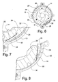
Figure 6 shows a further cross sectional view of the trocar shown in the previous figures, with the expansion sectors in its initial position and with a ratchet mechanism for keeping the sectors in stable intermediate expansion positions between their initial and final positions; -
Figure 7 shows an enlarged view of a portion of the cross section of the trocar offigure 6 relevant to the ratchet mechanism; -
Figure 8 shows a portion of the trocar along a cross section analogous to that offigure 7 showing the ratchet mechanism when the sectors are in their final, maximum expansion position; -
Figure 9 shows a longitudinal sectional view of the trocar of the previous figures, with the expansion sectors in the initial position and with an accessory element for locking the expansion sectors during the insertion step in the opening for accessing the body cavity; -
Figure 10 shows a cross section of the trocar with the expansion sector locking element as infigure 9 ; -
Figure 11 shows an axonometric view of the trocar of the preceding figures, with the expansion sectors in the initial position and with a key for facilitating the movement of the control ring nut when positioning the expansion sectors. - With reference to the aforesaid figures, a trocar for thoracic surgery according to the invention is generally indicated with 10 and comprises a guide duct T for surgical instruments adapted to be inserted in a body opening for accessing to the thoracic cavity. Duct T comprises a plurality of
sectors 11 arranged around theaxis 12 of the duct T and articulated to asupport frame 13. - Associated with such duct T are expansion means 14 (described below) from an initial insertion position in the body opening (see
figures 2 and 3 ) to a final, maximum expansion position (seefigures 4 and 5 ) in which the sectors are moved away from theaxis 12 to a greater extent than in the configuration assumed when they are in the initial position. - Each
sector 11 comprises alongitudinal body 15 extending parallel to theaxis 12. A preferablycurved arm 16, connected at a free end to theframe 13 by means of ahinge pin 17, extends from one end of thelongitudinal body 15 and on a plane orthogonal to theaxis 12. It has to be noted that, when thesectors 11 are in their initial position, thelongitudinal bodies 15 form a cylindrical duct closed along its own side surface. - In the present embodiment, the
frame 13 comprises a firstannular element 18 having aninternal base 19, on which thearms 16 of thesectors 11 are slidingly housed, and alateral containment wall 20 for thecurved arms 16. - The
frame 13 also comprises a secondannular element 21, fixed to theupper edge 22 of thewall 20 of the firstannular element 18. Thehinge pins 17 for thearms 16 are connected to the secondannular element 21 and, in particular,pins 17 are partially inserted in throughholes 23 formed thereon. A thirdannular element 24 of theframe 13 is fixed to the secondannular element 21 on the opposite side relative to the firstannular element 18 and has an internalcylindrical side surface 25 that defines a rotational housing space for acontrol ring nut 26, for controlling the movement of thesectors 11. Thecontrol ring nut 26 is locked in the movement along theaxis 12 between the secondannular element 21 and a fourthannular element 27 fixed to the edge of the thirdannular element 24 on the opposite side with respect to the secondannular element 21. - The expansion means 14, which provide spreading out or opening out of the
sectors 11 comprise thecontrol ring nut 26 and on the surface of thenut 26 facing towards the secondannular element 21pins 28 are provided that extend until they come into contact with theinner sides 16a, i.e. the concave sides facing towards theaxis 12, ofrespective arms 16. Following a rotation of thecontrol ring nut 26 in one direction, from hereafter referred to as expansion direction, thepins 28 are adapted to slide along theinner sides 16a in order to permit the opening movement of thesectors 11 from the initial insertion position (figure 2 ) in the body opening for accessing to the thoracic cavity, to the final, maximum expansion position (figure 4 ). Oninner sides 16a, at the attachment end zone of thearms 16 to thelongitudinal bodies 15,end stop abutments 16b are formed for thepins 28 when thesectors 11 are in the maximum expansion position. - The
ring nut 26 has, on the surface opposite that where thepins 28 are formed, two diametrically opposedreliefs 26a that constitute grip elements for the surgeon's hand or abutment elements for an accessory element, such as a key C that allows the movement of the control ring nut, as shown in figure 13 and as will be better explained below. - Associated with the
control ring nut 26 are means 29 for locking the rotation of the same ring nut in the direction opposite the expansion direction. In this embodiment, themeans 29 for locking the rotation of thering nut 26 are, for example, a ratchet mechanism interposed between thesupport frame 13 and thering nut 26. In particular, the ratchet mechanism comprises a toothed portion 30 (with saw tooth shape), defined on theinner side surface 25 of the thirdannular element 24, and apawl 31 elastically engageable with thetoothed portion 30. Thepawl 31 is for example formed by an elastic plate fixed at one end to the cylindrical side of thering nut 26, the other end being free to slide on thetoothed portion 30, in the direction permitted by the slope of the teeth. - The rotation locking means 29 moreover comprise a
device 32 for temporarily removing the ring nut rotation hindrance that, with reference to the ratchet mechanism just described, is formed by a disengagement device of thepawl 31 from thetoothed portion 30. As is clearly visible infigures 7 and 8 , thepawl 31 is arranged in arecess 33 on the cylindrical flank of thering nut 26. Thedevice 32 consists of atongue 34, slidably arranged between the cylindrical flank of thering nut 26 and theinner side surface 25 of the thirdannular element 24. Depending on the angular position taken along the cylindrical flank of thering nut 26, thetongue 34 can be interposed between the free end of the elastic plate forming thepawl 31 and thetoothed portion 30, thus permitting the disengagement of the pawl. Thetongue 34 has acontrol appendage 35 that projects in the direction opposite the extension of thelongitudinal bodies 15. Thecontrol appendage 35 is provided at one of the tworeliefs 26a, and faces thereto. - It is noted how the width of the control appendage is greater than the width of the
corresponding relief 26a. - In the maximum opening position of the trocar, or the final, maximum expansion position of the
sectors 11, the trocar is in stable equilibrium and cannot be spontaneously closed due to the radial pressure exerted by the expanded tissues, while in the partial opening configurations, the ratchet mechanism prevents the spontaneous closure due to said pressure. - In order to close the trocar and bring the
sectors 11 back into the initial insertion position in the opening made in the tissues to access the thoracic cavity, it is necessary to move thetongue 34. Thetongue 34 can carry out a short rotation relative to thering nut 13 by passing from the locking position (figure 8 ) to the release position (figures 6 and 7 ). In the locking position, the elastic plate forming thepawl 31 is free to engage on thetoothed portion 32 of the thirdannular element 24, while in the release position thetongue 34 causes the elastic plate to be bent, forcing it to abandon the grip on thetoothed portion 31 and rearranging it inside therecess 33. - In order to expand the trocar, it is necessary to rotate the
ring nut 26 in anticlockwise direction by operating onreliefs 26a by hand or with the suitable key C of figure 13. Since thecontrol appendage 35 of thetongue 34 has a width greater than that of thecorresponding relief 26a to which it faces, the right side of thecontrol appendage 35 is first aligned with the right side of therelief 26a of thering nut 26, bringing thetongue 34 from a release position, in which it is interposed between thepawl 31 and thetoothed portion 30, to the locking position, in which thepawl 31 is free to engage on the saw teeth. A further rotation of the key (or hand) causes thepins 28 of thering nut 26 to push thearms 16 towards the outside, with consequent moving away of thesectors 11 from theaxis 12. The sectors will always remain in expanded state thanks to the ratchet mechanism, when in operation. - The key C has an
end portion 36 adapted for being inserted in thehole 26b of thering nut 26 and twoside abutment portions 37 that cooperate with thecontrol appendage 35 and thereliefs 26a. Moreover the key C has ahole 38 through which the surgeon distinguishes by the touch the grip side for the opening of the trocar from the grip side for the closing. - The annular elements forming the
frame 13 are connected by threaded connections passing through the annular elements, such as for example a pair ofopposing screws 39 passing throughcorresponding eyelets 40 formed peripherally on theannular elements - The expansion of the
sectors 11 is in practice monodirectional, as the threelongitudinal bodies 15 are free to be moved away from theaxis 12 but not to return back, by virtue of the ratchet mechanism. This is not a problem when the trocar is inserted in the patient's thorax, as sector expansion is opposed by the radial forces exerted by the elastic resistance of the patient tissues, but could constitute a drawback on the trocar insertion step, as a possible abutment contact could generate radial thrusts causing the sectors to expand before the insertion. Therefore, in order to avoid such risk, a further accessory element is provided, like an inserter tool U for preventing the expansion of thesectors 11 from the initial insertion position. This tool is usually associated with the trocar on the insertion step in the body opening and is subsequently removed before starting the expansion step. - In particular, in this embodiment, such inserter tool U, visible in
figures 9 and 10 , has aplate 41 with a shape complementary to the hole of thering nut 26 and adapted to be inserted therein.Pins 42 are provided on the side of theplate 41 facing towards thesectors 11, each pin abutting against theexternal flank 16c of arespective arm 16, opposite theinternal flank 16a on which thepins 28 of thering nut 26 slide. The inserter tool U is secured to thering nut 26 by means of a locking and positioning element (not shown in the drawings) projecting from the side of theplate 41 and adapted to be coupled with agroove 42 formed on the inner side surface of thering nut 26. Advantageously, a rod-like portion 43 extends from theplate 41, in such a way to occupy the space defined between thelongitudinal bodies 15 forming thesectors 11. The rod-like portion 43 projects from the duct T formed bysector 11 with one sphere-shapedend 44 that makes the insertion of the trocar in the body opening easier. On the opposite side, theplate 41 has agrip handle 45. - In order to prevent the trocar from slipping outside the opening made in the patient's thorax during the operation, the surgeon can secure the trocar to the thorax by means of fixing means, such as for example
small rings 46 formed along the outside of theframe 13 and through which the surgeon can pass suture points for anchoring them to the patient's skin. Alternatively, thelongitudinal bodies 15 forming the expansion sectors can be made with external surface with increased friction, by means of saw tooth corrugations or threads (elements not shown in the drawings for the sake of simplicity). - It is evident how the trocar described here is easily insertable in the body opening of access to the thoracic cavity, as during the insertion, the trocar sectors defining the access duct to the thoracic cavity have a very limited axial size. When the trocar is inserted in the thorax, the sectors can radially expand by enlarging the thoracic cavity access opening in order to permit the easy insertion of the surgical instruments.
- In practice, a trocar and a retractor have been joined in a single instrument. Thus the number of tools to be used is reduced and the trocar insertion process simplified, entirely to the advantage of the surgeon who does not need to use additional instruments while the preliminary operating steps of the operation are reduced.
- The trocar according to the invention can be subject to numerous modifications and variants, all being within the scope of the invention; moreover, all details can be replaced by other technically equivalent elements, without departing from the scope of the invention.
- In practice, the materials used (provided that they are compatible with the specific use) as well as the size can be of any type according to technical requirements and the state of the art.
- Where any of the characteristics and techniques mentioned in any claim are followed by a reference number, these have been included as an example with the sole object of increasing the clarity of the claims, and consequently they have no limiting effect on the interpretation of each element identified thereby.
Claims (20)
- Trocar for thoracic surgery, comprising a guide duct (T) for surgical instruments adapted to be inserted in a body opening of access to the thoracic cavity, characterised in that said duct (T) is formed by a plurality of sectors (11) arranged around its axis (12) and articulated to a support frame (13), sector expansion means (14) being associated with said duct (T) for mutually displacing said sectors (11) from an initial insertion position in the body opening to a final, maximum expansion position in which they are moved away from said axis (12) to a greater extent than in the configuration assumed in said initial position, said expansion means (14) comprising a control ring nut (26) movably connected with said sectors (11) and said support frame (13), such that a rotation of said ring nut (26) in one direction, called the expansion direction, results in a movement of the sectors (11) away of said axis (12), means for locking the rotation (29) in the direction opposite that of said expansion direction being associated with said ring nut (26), said rotation locking means (29) comprising a device (32) for temporarily removing the rotation hindrance of the ring nut (26) in the direction opposite the expansion direction, whereby the sectors (11) can move backwards to said initial position.
- Trocar according to claim 1, characterised in that the rotation locking means (29) of said control ring nut (26) in the expansion direction comprise a ratchet mechanism interposed between said frame (13) and said control ring nut (26).
- Trocar according to claim 2, characterised in that said ratchet mechanism comprises a toothed portion (30) with saw tooth profile formed on said frame, a pawl (31) elastically associated with said control ring nut (26), one end of the pawl (31) being free to slide on said toothed portion (30) in the direction permitted by the slope of the teeth, said device (32) for temporarily removing the rotation hindrance of the ring nut (26) in the direction opposite the expansion direction comprising a disengagement device of said pawl (31) from said toothed portion (30).
- Trocar according to claim 3, characterised in that said frame (13) internally defines a rotational housing space for said control ring nut (26), said toothed portion (30) with saw tooth profile being formed on the inner side surface (25) of said housing space for said control ring nut (26), said pawl (31) being formed by an elastic plate with one end fixed to the cylindrical flank of said control ring nut (26) and with the other end free to slide on said toothed portion (30) in the direction permitted by the slope of the teeth, said device (32) for disengaging the pawl (31) from the toothed portion (30) comprising a tongue (34) slidably arranged between the cylindrical flank of the control ring nut (26) and said inner side surface (25) of the frame (13), said tongue (34) being adapted to be interposed between the free end of the elastic plate forming the pawl (31) and said toothed portion (30) according to the angular position along the cylindrical flank of the control ring nut (26), thus permitting the disengagement of the pawl (31).
- Trocar according to claim 4, characterised in that said control ring nut (26) has at least one relief (26a) constituting either a grip element for the surgeon's hand or abutment element for a driving key (C) of the ring nut (26), said at least one relief (26a) extending in the direction opposite the extension direction of said sectors (11), said disengagement tongue (34) of the pawl (31) of the ratchet mechanism having a control appendage (35) provided at said at least one relief (26a) and facing the latter (26a), the width of said control appendage (35) being greater than the width of the corresponding said at least one relief (26a).
- Trocar according to any one of the preceding claims, characterised in that each of said sectors (11) comprises a longitudinal body (15) that is extended in the same direction of said axis (12), an arm (16) articulated at one free end to said frame (13) by means of a hinge pin (17) extending from one end of said longitudinal body (15), on a plane substantially orthogonal to said axis (12).
- Trocar according to claim 6, characterised in that, when said sectors (11) are in the initial insertion position, said longitudinal bodies (15) form a cylindrical duct that is substantially closed along its own side surface.
- Trocar according to claim 6 or 7, characterised in that each arm (16) is curved with concavity turned towards said axis (12).
- Trocar according to any one of the claims 6 to 8, characterised in that said frame (13) is annular and surrounds said sectors (11), said frame (13) comprising- a first annular element (18) having an inner base (19) on which the arms (16) of said sectors (11) slidably abut, and a lateral containment side (20) for said arms (16),- a second annular element (21), fixed on the upper edge (22) of said side (20) of said first annular element (18), to which (21) hinge pins (17) for the arms (16) are bonded,- a third annular element (24) fixed on said second annular element (21) on the part opposite the first annular element (18), said third annular element (24) having a cylindrical inner side surface (25) that defines a rotational housing space for said control ring nut (26),- a fourth annular element (27) fixed on the edge of the third annular element (24) on the side opposite the second annular element (21), said control ring nut (16) being locked in movement along the axis (12) between the second annular element (21) and the fourth annular element (27).
- Trocar according to claim 9, characterised in that the joining of said first, second, third and fourth annular element (18, 21, 24, 27) forming the frame (13) is achieved by two opposing screws (39) passing through corresponding eyelets (40) made peripherally on the same annular elements (18, 21, 24, 27).
- Trocar according to any one of the claims 4 and 9, characterised in that said toothed portion (30) of the ratchet mechanism is formed on the inner side surface (25) of said third annular element (24) of the frame (13).
- Trocar according to any one of the claims 6 to 10, characterised in that said expansion means (14) comprise pins (28) that are extended from the surface of said control ring nut (26) up to contact with the inner flanks (16a) of said arms (16), said pins (28) being slidable on said flanks (16a) to allow the opening movement of said sectors (11) from the initial insertion position in the body opening for accessing to the thoracic cavity to the final maximum expansion position.
- Trocar according to claim 12, characterised in that on said inner flanks (16a) of said arms (16), at the attachment end zone of the arms (16) to the longitudinal bodies (15) forming said sectors (11), end stop abutments (16b) are formed for said pins (28) when the sectors (11) are in the maximum expansion position.
- Trocar according to any one of the preceding claims, characterised in that it comprises fixing means to the patient's thorax.
- Trocar according to claim 14, characterised in that said fixing means comprise small rings (46) made along the outside of said frame (13) adapted to permit the passage of suture points for anchoring to the patient's skin.
- Trocar according to one or more of the preceding claims, characterised in that it comprises an accessory element constituted by an inserter tool (U) adapted to lock the expansion of said sectors (11) in the initial insertion position, said inserter tool (U) being associable with the trocar body (10) only in the insertion step in the body opening and being subsequently removed before beginning the expansion step.
- Trocar according to claim 16, characterised in that said inserted tool (U) has a plate (41) countershaped to the hole (26b) of said control ring nut (26) and fit for being inserted therein (26b), said plate (41) having, on the face turned towards said sectors (11), pins (42) adapted to abut against the external flanks (16c), opposite the internal flanks (16a) on which the pins (28) of said control ring nut (26) slide, of respective arms (16), said inserter tool (U) being locked on said control ring nut (26) by means of a locking and positioning element projecting from the side of said plate (41) and adapted to be coupled with a corresponding groove (42) made on the inner side surface of said control ring nut (26).
- Trocar according to claim 17, characterised in that, a rod-like portion (43) extends from said plate (41) in the space defined between the longitudinal bodies (15) forming said sectors (11), said rod-like portion projecting from the duct formed by these (11) with a shaped end (44) to make easier the insertion of the trocar in the body opening.
- Trocar, according to any one of the preceding claims, characterised in that it comprises an accessory element formed by a key (C) that can be coupled with said control ring nut (26) to control its rotation.
- Trocar according to claim 19, characterised in that said key (C) has an end portion (36) engageable in the hole (26b) of said control ring nut (26), and at least one side abutment portion (37) that interacts with said control appendage (35) of said ratchet mechanism and with said at least one relief (26a) of said ring nut (26), said key (C) having means (38) for distinguishing the grip side for the opening of the trocar from the grip side for the closing.
Applications Claiming Priority (1)
| Application Number | Priority Date | Filing Date | Title |
|---|---|---|---|
| IT000060A ITFI20070060A1 (en) | 2007-03-14 | 2007-03-14 | TROCAR FOR THORACIC SURGERY |
Publications (2)
| Publication Number | Publication Date |
|---|---|
| EP1970012A1 true EP1970012A1 (en) | 2008-09-17 |
| EP1970012B1 EP1970012B1 (en) | 2011-11-02 |
Family
ID=39551535
Family Applications (1)
| Application Number | Title | Priority Date | Filing Date |
|---|---|---|---|
| EP08102428A Not-in-force EP1970012B1 (en) | 2007-03-14 | 2008-03-10 | Trocar for thoracic surgery |
Country Status (7)
| Country | Link |
|---|---|
| US (1) | US20090209913A1 (en) |
| EP (1) | EP1970012B1 (en) |
| AT (1) | ATE531322T1 (en) |
| DK (1) | DK1970012T3 (en) |
| ES (1) | ES2376051T3 (en) |
| HR (1) | HRP20110983T1 (en) |
| IT (1) | ITFI20070060A1 (en) |
Cited By (2)
| Publication number | Priority date | Publication date | Assignee | Title |
|---|---|---|---|---|
| CN109821142A (en) * | 2019-04-11 | 2019-05-31 | 河南科技大学第一附属医院 | A kind of medical procteurynter of rotating disc type |
| WO2021150927A1 (en) * | 2020-01-22 | 2021-07-29 | Minnetronix Neuro, Inc. | Medical device for accessing the central nervous system |
Families Citing this family (18)
| Publication number | Priority date | Publication date | Assignee | Title |
|---|---|---|---|---|
| US7762990B2 (en) * | 2007-05-24 | 2010-07-27 | Tyco Healthcare Group Lp | Surgical access apparatus with centering mechanism |
| US20100274094A1 (en) * | 2009-04-23 | 2010-10-28 | Custom Spine, Inc. | Tissue Retraction Apparatus |
| US8808248B2 (en) * | 2009-10-15 | 2014-08-19 | Biosense Webster, Inc. | Catheter sheath introducer with rotational lock |
| KR101287138B1 (en) | 2011-06-15 | 2013-07-17 | 국립암센터 | Trocar |
| EP2695581B1 (en) | 2012-08-07 | 2019-03-13 | Critical Innovations, LLC | Device for simultaneously documenting and treating tension pneumothorax and/or hemothorax |
| US9687273B2 (en) * | 2013-09-11 | 2017-06-27 | Gimmi Gmbh | Endoscopic surgical instruments and related methods |
| US10046147B2 (en) | 2013-12-26 | 2018-08-14 | Critical Innovations, LLC | Percutaneous access pathway system and method |
| CN105342672B (en) * | 2015-09-22 | 2017-08-01 | 杭州承诺医疗科技有限公司 | A kind of medical thrust expands implanting instrument |
| CN109567907B (en) * | 2017-06-03 | 2023-06-30 | 成都五义医疗科技有限公司 | Reducing sleeve device with driving structure and puncture outfit |
| CN107137132B (en) * | 2017-06-03 | 2019-02-12 | 成都五义医疗科技有限公司 | A kind of chuck mode reducing casing tube device and puncture outfit |
| CA2993590A1 (en) | 2017-09-06 | 2019-03-06 | Xpan Inc. | Radially expandable cannula system |
| US10814119B2 (en) | 2017-09-22 | 2020-10-27 | Critical Innovations, LLC | Percutaneous access pathway system |
| US10758270B2 (en) * | 2017-10-06 | 2020-09-01 | Ethicon Llc | Surgical tool stabilization devices for trocar assemblies |
| US11696784B2 (en) | 2018-01-26 | 2023-07-11 | Maine Medical Center | Angled surgical trocars |
| CN110464899B (en) * | 2019-08-23 | 2021-05-18 | 安徽医科大学第一附属医院 | Enema device |
| AU2021233207A1 (en) | 2020-03-13 | 2022-11-03 | Xpan Inc. | Radially expandable cannula devices, and systems and methods for using them |
| IT202100011465A1 (en) * | 2021-05-05 | 2022-11-05 | Carmine Antropoli | MECHANICAL IRIS DIAPHRAGM DILATOR |
| CN113440185B (en) * | 2021-07-16 | 2024-02-02 | 瑞柏生物(中国)股份有限公司 | Gynaecology's fast regulating type expands palace device |
Citations (5)
| Publication number | Priority date | Publication date | Assignee | Title |
|---|---|---|---|---|
| GB330629A (en) | 1929-03-14 | 1930-06-16 | Edward Baron | Improvements in and connected with vaginal specula and like instruments |
| US20050165281A1 (en) | 2004-01-27 | 2005-07-28 | Sundaram Ravikumar | Surgical retractor apparatus for use with a surgical port |
| US20060052672A1 (en) | 2004-09-09 | 2006-03-09 | Landry Michael E | Surgical retraction apparatus method of use |
| WO2006117819A1 (en) | 2005-04-29 | 2006-11-09 | Elenor S.R.L. | Radially expandable anchorage guide for trocars |
| US20070010716A1 (en) | 2005-07-11 | 2007-01-11 | Malandain Hugues F | Surgical access device, system, and methods of use |
Family Cites Families (4)
| Publication number | Priority date | Publication date | Assignee | Title |
|---|---|---|---|---|
| US3788318A (en) * | 1972-06-12 | 1974-01-29 | S Kim | Expandable cannular, especially for medical purposes |
| US3789852A (en) * | 1972-06-12 | 1974-02-05 | S Kim | Expandable trochar, especially for medical purposes |
| US6354995B1 (en) * | 1998-04-24 | 2002-03-12 | Moshe Hoftman | Rotational lateral expander device |
| US7699864B2 (en) * | 2004-03-18 | 2010-04-20 | Onset Medical Corporation | Expandable medical access device |
-
2007
- 2007-03-14 IT IT000060A patent/ITFI20070060A1/en unknown
-
2008
- 2008-03-10 EP EP08102428A patent/EP1970012B1/en not_active Not-in-force
- 2008-03-10 DK DK08102428.3T patent/DK1970012T3/en active
- 2008-03-10 AT AT08102428T patent/ATE531322T1/en active
- 2008-03-10 ES ES08102428T patent/ES2376051T3/en active Active
- 2008-03-14 US US12/075,886 patent/US20090209913A1/en not_active Abandoned
-
2011
- 2011-12-30 HR HR20110983T patent/HRP20110983T1/en unknown
Patent Citations (5)
| Publication number | Priority date | Publication date | Assignee | Title |
|---|---|---|---|---|
| GB330629A (en) | 1929-03-14 | 1930-06-16 | Edward Baron | Improvements in and connected with vaginal specula and like instruments |
| US20050165281A1 (en) | 2004-01-27 | 2005-07-28 | Sundaram Ravikumar | Surgical retractor apparatus for use with a surgical port |
| US20060052672A1 (en) | 2004-09-09 | 2006-03-09 | Landry Michael E | Surgical retraction apparatus method of use |
| WO2006117819A1 (en) | 2005-04-29 | 2006-11-09 | Elenor S.R.L. | Radially expandable anchorage guide for trocars |
| US20070010716A1 (en) | 2005-07-11 | 2007-01-11 | Malandain Hugues F | Surgical access device, system, and methods of use |
Cited By (3)
| Publication number | Priority date | Publication date | Assignee | Title |
|---|---|---|---|---|
| CN109821142A (en) * | 2019-04-11 | 2019-05-31 | 河南科技大学第一附属医院 | A kind of medical procteurynter of rotating disc type |
| CN109821142B (en) * | 2019-04-11 | 2021-04-23 | 河南科技大学第一附属医院 | Rotating disc type medical anus dilator |
| WO2021150927A1 (en) * | 2020-01-22 | 2021-07-29 | Minnetronix Neuro, Inc. | Medical device for accessing the central nervous system |
Also Published As
| Publication number | Publication date |
|---|---|
| ES2376051T3 (en) | 2012-03-08 |
| HRP20110983T1 (en) | 2012-03-31 |
| US20090209913A1 (en) | 2009-08-20 |
| EP1970012B1 (en) | 2011-11-02 |
| ITFI20070060A1 (en) | 2008-09-15 |
| DK1970012T3 (en) | 2012-02-27 |
| ATE531322T1 (en) | 2011-11-15 |
Similar Documents
| Publication | Publication Date | Title |
|---|---|---|
| EP1970012B1 (en) | Trocar for thoracic surgery | |
| US11284887B2 (en) | Bone implant with means for multi directional force and means of insertion | |
| EP2417922B1 (en) | Expandable thoracic access port | |
| KR101687977B1 (en) | Interspinous process implant and fusion cage spacer | |
| US8821392B2 (en) | Surgical retention port and method of use | |
| US8267859B2 (en) | Spreader insert for a retractor system | |
| US8409085B2 (en) | Surgical retention port and method of use | |
| EP2283778B1 (en) | Surgical retractor | |
| AU762195B2 (en) | Self-retaining surgical access instrument | |
| JP4642769B2 (en) | Expandable surgical access device | |
| EP2502568A1 (en) | Surgical retractor including rotatable knobs | |
| EP2609880A1 (en) | Wound protector with reinforced ring | |
| JP2014534869A (en) | Osteosynthesis clip | |
| JP2009514651A (en) | Trocar with excellent fixing ability | |
| WO2009076188A2 (en) | Retractor and sealing system for surgical/non-surgical instruments | |
| EP2078505B1 (en) | Access assembly with adjustable seal member | |
| EP3360493B1 (en) | Iris valve with novel locking mechanism and control ring |
Legal Events
| Date | Code | Title | Description |
|---|---|---|---|
| PUAI | Public reference made under article 153(3) epc to a published international application that has entered the european phase |
Free format text: ORIGINAL CODE: 0009012 |
|
| AK | Designated contracting states |
Kind code of ref document: A1 Designated state(s): AT BE BG CH CY CZ DE DK EE ES FI FR GB GR HR HU IE IS IT LI LT LU LV MC MT NL NO PL PT RO SE SI SK TR |
|
| AX | Request for extension of the european patent |
Extension state: AL BA MK RS |
|
| 17P | Request for examination filed |
Effective date: 20081128 |
|
| 17Q | First examination report despatched |
Effective date: 20090107 |
|
| AKX | Designation fees paid |
Designated state(s): AT BE BG CH CY CZ DE DK EE ES FI FR GB GR HR HU IE IS IT LI LT LU LV MC MT NL NO PL PT RO SE SI SK TR |
|
| GRAP | Despatch of communication of intention to grant a patent |
Free format text: ORIGINAL CODE: EPIDOSNIGR1 |
|
| GRAS | Grant fee paid |
Free format text: ORIGINAL CODE: EPIDOSNIGR3 |
|
| RAP1 | Party data changed (applicant data changed or rights of an application transferred) |
Owner name: AB MEDICA S.P.A. |
|
| GRAA | (expected) grant |
Free format text: ORIGINAL CODE: 0009210 |
|
| AK | Designated contracting states |
Kind code of ref document: B1 Designated state(s): AT BE BG CH CY CZ DE DK EE ES FI FR GB GR HR HU IE IS IT LI LT LU LV MC MT NL NO PL PT RO SE SI SK TR |
|
| REG | Reference to a national code |
Ref country code: GB Ref legal event code: FG4D |
|
| REG | Reference to a national code |
Ref country code: CH Ref legal event code: EP |
|
| REG | Reference to a national code |
Ref country code: IE Ref legal event code: FG4D |
|
| REG | Reference to a national code |
Ref country code: DE Ref legal event code: R096 Ref document number: 602008011008 Country of ref document: DE Effective date: 20111229 |
|
| REG | Reference to a national code |
Ref country code: HR Ref legal event code: TUEP Ref document number: P20110983 Country of ref document: HR |
|
| REG | Reference to a national code |
Ref country code: NL Ref legal event code: T3 |
|
| REG | Reference to a national code |
Ref country code: CH Ref legal event code: NV Representative=s name: RENTSCH PARTNER AG |
|
| REG | Reference to a national code |
Ref country code: SE Ref legal event code: TRGR |
|
| REG | Reference to a national code |
Ref country code: DK Ref legal event code: T3 |
|
| REG | Reference to a national code |
Ref country code: ES Ref legal event code: FG2A Ref document number: 2376051 Country of ref document: ES Kind code of ref document: T3 Effective date: 20120308 |
|
| REG | Reference to a national code |
Ref country code: NO Ref legal event code: T2 Effective date: 20111102 |
|
| REG | Reference to a national code |
Ref country code: HR Ref legal event code: T1PR Ref document number: P20110983 Country of ref document: HR |
|
| LTIE | Lt: invalidation of european patent or patent extension |
Effective date: 20111102 |
|
| PG25 | Lapsed in a contracting state [announced via postgrant information from national office to epo] |
Ref country code: LT Free format text: LAPSE BECAUSE OF FAILURE TO SUBMIT A TRANSLATION OF THE DESCRIPTION OR TO PAY THE FEE WITHIN THE PRESCRIBED TIME-LIMIT Effective date: 20111102 Ref country code: IS Free format text: LAPSE BECAUSE OF FAILURE TO SUBMIT A TRANSLATION OF THE DESCRIPTION OR TO PAY THE FEE WITHIN THE PRESCRIBED TIME-LIMIT Effective date: 20120302 |
|
| PG25 | Lapsed in a contracting state [announced via postgrant information from national office to epo] |
Ref country code: PL Free format text: LAPSE BECAUSE OF FAILURE TO SUBMIT A TRANSLATION OF THE DESCRIPTION OR TO PAY THE FEE WITHIN THE PRESCRIBED TIME-LIMIT Effective date: 20111102 Ref country code: SI Free format text: LAPSE BECAUSE OF FAILURE TO SUBMIT A TRANSLATION OF THE DESCRIPTION OR TO PAY THE FEE WITHIN THE PRESCRIBED TIME-LIMIT Effective date: 20111102 Ref country code: GR Free format text: LAPSE BECAUSE OF FAILURE TO SUBMIT A TRANSLATION OF THE DESCRIPTION OR TO PAY THE FEE WITHIN THE PRESCRIBED TIME-LIMIT Effective date: 20120203 Ref country code: LV Free format text: LAPSE BECAUSE OF FAILURE TO SUBMIT A TRANSLATION OF THE DESCRIPTION OR TO PAY THE FEE WITHIN THE PRESCRIBED TIME-LIMIT Effective date: 20111102 Ref country code: BE Free format text: LAPSE BECAUSE OF FAILURE TO SUBMIT A TRANSLATION OF THE DESCRIPTION OR TO PAY THE FEE WITHIN THE PRESCRIBED TIME-LIMIT Effective date: 20111102 Ref country code: PT Free format text: LAPSE BECAUSE OF FAILURE TO SUBMIT A TRANSLATION OF THE DESCRIPTION OR TO PAY THE FEE WITHIN THE PRESCRIBED TIME-LIMIT Effective date: 20120302 |
|
| PG25 | Lapsed in a contracting state [announced via postgrant information from national office to epo] |
Ref country code: CY Free format text: LAPSE BECAUSE OF FAILURE TO SUBMIT A TRANSLATION OF THE DESCRIPTION OR TO PAY THE FEE WITHIN THE PRESCRIBED TIME-LIMIT Effective date: 20111102 |
|
| PG25 | Lapsed in a contracting state [announced via postgrant information from national office to epo] |
Ref country code: BG Free format text: LAPSE BECAUSE OF FAILURE TO SUBMIT A TRANSLATION OF THE DESCRIPTION OR TO PAY THE FEE WITHIN THE PRESCRIBED TIME-LIMIT Effective date: 20120202 Ref country code: CZ Free format text: LAPSE BECAUSE OF FAILURE TO SUBMIT A TRANSLATION OF THE DESCRIPTION OR TO PAY THE FEE WITHIN THE PRESCRIBED TIME-LIMIT Effective date: 20111102 Ref country code: SK Free format text: LAPSE BECAUSE OF FAILURE TO SUBMIT A TRANSLATION OF THE DESCRIPTION OR TO PAY THE FEE WITHIN THE PRESCRIBED TIME-LIMIT Effective date: 20111102 Ref country code: EE Free format text: LAPSE BECAUSE OF FAILURE TO SUBMIT A TRANSLATION OF THE DESCRIPTION OR TO PAY THE FEE WITHIN THE PRESCRIBED TIME-LIMIT Effective date: 20111102 |
|
| PG25 | Lapsed in a contracting state [announced via postgrant information from national office to epo] |
Ref country code: RO Free format text: LAPSE BECAUSE OF FAILURE TO SUBMIT A TRANSLATION OF THE DESCRIPTION OR TO PAY THE FEE WITHIN THE PRESCRIBED TIME-LIMIT Effective date: 20111102 |
|
| PLBE | No opposition filed within time limit |
Free format text: ORIGINAL CODE: 0009261 |
|
| STAA | Information on the status of an ep patent application or granted ep patent |
Free format text: STATUS: NO OPPOSITION FILED WITHIN TIME LIMIT |
|
| 26N | No opposition filed |
Effective date: 20120803 |
|
| PG25 | Lapsed in a contracting state [announced via postgrant information from national office to epo] |
Ref country code: MC Free format text: LAPSE BECAUSE OF NON-PAYMENT OF DUE FEES Effective date: 20120331 |
|
| REG | Reference to a national code |
Ref country code: DE Ref legal event code: R097 Ref document number: 602008011008 Country of ref document: DE Effective date: 20120803 |
|
| PG25 | Lapsed in a contracting state [announced via postgrant information from national office to epo] |
Ref country code: FI Free format text: LAPSE BECAUSE OF FAILURE TO SUBMIT A TRANSLATION OF THE DESCRIPTION OR TO PAY THE FEE WITHIN THE PRESCRIBED TIME-LIMIT Effective date: 20111102 |
|
| PG25 | Lapsed in a contracting state [announced via postgrant information from national office to epo] |
Ref country code: MT Free format text: LAPSE BECAUSE OF FAILURE TO SUBMIT A TRANSLATION OF THE DESCRIPTION OR TO PAY THE FEE WITHIN THE PRESCRIBED TIME-LIMIT Effective date: 20111102 |
|
| REG | Reference to a national code |
Ref country code: HR Ref legal event code: ODRP Ref document number: P20110983 Country of ref document: HR Payment date: 20140304 Year of fee payment: 7 |
|
| PG25 | Lapsed in a contracting state [announced via postgrant information from national office to epo] |
Ref country code: TR Free format text: LAPSE BECAUSE OF FAILURE TO SUBMIT A TRANSLATION OF THE DESCRIPTION OR TO PAY THE FEE WITHIN THE PRESCRIBED TIME-LIMIT Effective date: 20111102 |
|
| PGFP | Annual fee paid to national office [announced via postgrant information from national office to epo] |
Ref country code: NO Payment date: 20140313 Year of fee payment: 7 Ref country code: DK Payment date: 20140319 Year of fee payment: 7 Ref country code: SE Payment date: 20140319 Year of fee payment: 7 Ref country code: IE Payment date: 20140325 Year of fee payment: 7 Ref country code: LU Payment date: 20140326 Year of fee payment: 7 Ref country code: NL Payment date: 20140319 Year of fee payment: 7 Ref country code: CH Payment date: 20140319 Year of fee payment: 7 Ref country code: DE Payment date: 20140328 Year of fee payment: 7 |
|
| PGFP | Annual fee paid to national office [announced via postgrant information from national office to epo] |
Ref country code: HR Payment date: 20140304 Year of fee payment: 7 Ref country code: FR Payment date: 20140319 Year of fee payment: 7 Ref country code: AT Payment date: 20140312 Year of fee payment: 7 |
|
| PGFP | Annual fee paid to national office [announced via postgrant information from national office to epo] |
Ref country code: GB Payment date: 20140319 Year of fee payment: 7 |
|
| PG25 | Lapsed in a contracting state [announced via postgrant information from national office to epo] |
Ref country code: HU Free format text: LAPSE BECAUSE OF FAILURE TO SUBMIT A TRANSLATION OF THE DESCRIPTION OR TO PAY THE FEE WITHIN THE PRESCRIBED TIME-LIMIT Effective date: 20080310 |
|
| PGFP | Annual fee paid to national office [announced via postgrant information from national office to epo] |
Ref country code: IT Payment date: 20150310 Year of fee payment: 8 |
|
| REG | Reference to a national code |
Ref country code: DE Ref legal event code: R119 Ref document number: 602008011008 Country of ref document: DE |
|
| REG | Reference to a national code |
Ref country code: HR Ref legal event code: PBON Ref document number: P20110983 Country of ref document: HR Effective date: 20150310 |
|
| REG | Reference to a national code |
Ref country code: NO Ref legal event code: MMEP Ref country code: DK Ref legal event code: EBP Effective date: 20150331 |
|
| PG25 | Lapsed in a contracting state [announced via postgrant information from national office to epo] |
Ref country code: LU Free format text: LAPSE BECAUSE OF NON-PAYMENT OF DUE FEES Effective date: 20150310 |
|
| REG | Reference to a national code |
Ref country code: CH Ref legal event code: PL |
|
| REG | Reference to a national code |
Ref country code: AT Ref legal event code: MM01 Ref document number: 531322 Country of ref document: AT Kind code of ref document: T Effective date: 20150310 |
|
| GBPC | Gb: european patent ceased through non-payment of renewal fee |
Effective date: 20150310 |
|
| PG25 | Lapsed in a contracting state [announced via postgrant information from national office to epo] |
Ref country code: SE Free format text: LAPSE BECAUSE OF NON-PAYMENT OF DUE FEES Effective date: 20150311 |
|
| REG | Reference to a national code |
Ref country code: SE Ref legal event code: EUG |
|
| REG | Reference to a national code |
Ref country code: NL Ref legal event code: MM Effective date: 20150401 |
|
| REG | Reference to a national code |
Ref country code: FR Ref legal event code: ST Effective date: 20151130 |
|
| REG | Reference to a national code |
Ref country code: IE Ref legal event code: MM4A |
|
| PG25 | Lapsed in a contracting state [announced via postgrant information from national office to epo] |
Ref country code: DE Free format text: LAPSE BECAUSE OF NON-PAYMENT OF DUE FEES Effective date: 20151001 Ref country code: NO Free format text: LAPSE BECAUSE OF NON-PAYMENT OF DUE FEES Effective date: 20150331 Ref country code: CH Free format text: LAPSE BECAUSE OF NON-PAYMENT OF DUE FEES Effective date: 20150331 Ref country code: LI Free format text: LAPSE BECAUSE OF NON-PAYMENT OF DUE FEES Effective date: 20150331 Ref country code: IE Free format text: LAPSE BECAUSE OF NON-PAYMENT OF DUE FEES Effective date: 20150310 Ref country code: GB Free format text: LAPSE BECAUSE OF NON-PAYMENT OF DUE FEES Effective date: 20150310 |
|
| PG25 | Lapsed in a contracting state [announced via postgrant information from national office to epo] |
Ref country code: FR Free format text: LAPSE BECAUSE OF NON-PAYMENT OF DUE FEES Effective date: 20150331 Ref country code: AT Free format text: LAPSE BECAUSE OF NON-PAYMENT OF DUE FEES Effective date: 20150310 Ref country code: HR Free format text: LAPSE BECAUSE OF NON-PAYMENT OF DUE FEES Effective date: 20150310 |
|
| PG25 | Lapsed in a contracting state [announced via postgrant information from national office to epo] |
Ref country code: DK Free format text: LAPSE BECAUSE OF NON-PAYMENT OF DUE FEES Effective date: 20150331 |
|
| PG25 | Lapsed in a contracting state [announced via postgrant information from national office to epo] |
Ref country code: ES Free format text: LAPSE BECAUSE OF NON-PAYMENT OF DUE FEES Effective date: 20150311 |
|
| PGFP | Annual fee paid to national office [announced via postgrant information from national office to epo] |
Ref country code: ES Payment date: 20140327 Year of fee payment: 7 |
|
| PG25 | Lapsed in a contracting state [announced via postgrant information from national office to epo] |
Ref country code: IT Free format text: LAPSE BECAUSE OF NON-PAYMENT OF DUE FEES Effective date: 20160310 |
|
| PG25 | Lapsed in a contracting state [announced via postgrant information from national office to epo] |
Ref country code: NL Free format text: LAPSE BECAUSE OF NON-PAYMENT OF DUE FEES Effective date: 20150401 |