EP1962705B1 - Flexible elongated chain implant - Google Patents
Flexible elongated chain implant Download PDFInfo
- Publication number
- EP1962705B1 EP1962705B1 EP06848070A EP06848070A EP1962705B1 EP 1962705 B1 EP1962705 B1 EP 1962705B1 EP 06848070 A EP06848070 A EP 06848070A EP 06848070 A EP06848070 A EP 06848070A EP 1962705 B1 EP1962705 B1 EP 1962705B1
- Authority
- EP
- European Patent Office
- Prior art keywords
- bone
- chain
- bodies
- flexible
- elongated member
- Prior art date
- Legal status (The legal status is an assumption and is not a legal conclusion. Google has not performed a legal analysis and makes no representation as to the accuracy of the status listed.)
- Active
Links
- 239000007943 implant Substances 0.000 title abstract description 73
- 238000003780 insertion Methods 0.000 claims abstract description 30
- 230000037431 insertion Effects 0.000 claims abstract description 30
- 230000003416 augmentation Effects 0.000 claims abstract description 12
- 239000000560 biocompatible material Substances 0.000 claims abstract description 6
- 210000000988 bone and bone Anatomy 0.000 claims description 170
- 239000004568 cement Substances 0.000 claims description 22
- 239000002639 bone cement Substances 0.000 claims description 19
- 239000003814 drug Substances 0.000 claims description 11
- 210000001519 tissue Anatomy 0.000 claims description 10
- 229940124597 therapeutic agent Drugs 0.000 claims description 9
- 239000011248 coating agent Substances 0.000 claims description 8
- 238000000576 coating method Methods 0.000 claims description 8
- 239000000126 substance Substances 0.000 claims description 7
- 230000008468 bone growth Effects 0.000 claims description 6
- 239000003242 anti bacterial agent Substances 0.000 claims description 4
- 230000003115 biocidal effect Effects 0.000 claims description 3
- 230000004936 stimulating effect Effects 0.000 claims description 2
- 238000000034 method Methods 0.000 abstract description 60
- 201000010099 disease Diseases 0.000 abstract description 6
- 208000037265 diseases, disorders, signs and symptoms Diseases 0.000 abstract description 6
- 230000002159 abnormal effect Effects 0.000 abstract description 3
- 230000007170 pathology Effects 0.000 abstract description 2
- 239000000463 material Substances 0.000 description 66
- 239000011797 cavity material Substances 0.000 description 20
- 230000001054 cortical effect Effects 0.000 description 16
- 239000000945 filler Substances 0.000 description 16
- 230000002328 demineralizing effect Effects 0.000 description 15
- 239000007787 solid Substances 0.000 description 13
- 239000011800 void material Substances 0.000 description 13
- 206010010214 Compression fracture Diseases 0.000 description 12
- 238000005115 demineralization Methods 0.000 description 12
- 206010017076 Fracture Diseases 0.000 description 11
- 239000003795 chemical substances by application Substances 0.000 description 11
- 230000008569 process Effects 0.000 description 11
- 210000000689 upper leg Anatomy 0.000 description 11
- 229920003229 poly(methyl methacrylate) Polymers 0.000 description 9
- 239000004926 polymethyl methacrylate Substances 0.000 description 9
- VEXZGXHMUGYJMC-UHFFFAOYSA-N Hydrochloric acid Chemical compound Cl VEXZGXHMUGYJMC-UHFFFAOYSA-N 0.000 description 8
- 238000002513 implantation Methods 0.000 description 8
- 239000011324 bead Substances 0.000 description 7
- 230000004927 fusion Effects 0.000 description 7
- 239000000853 adhesive Substances 0.000 description 6
- 230000001070 adhesive effect Effects 0.000 description 6
- 230000003190 augmentative effect Effects 0.000 description 6
- 208000015181 infectious disease Diseases 0.000 description 6
- 238000004519 manufacturing process Methods 0.000 description 6
- 238000011282 treatment Methods 0.000 description 6
- 206010028980 Neoplasm Diseases 0.000 description 5
- 239000002253 acid Substances 0.000 description 5
- 238000006073 displacement reaction Methods 0.000 description 5
- 230000000873 masking effect Effects 0.000 description 5
- 230000000399 orthopedic effect Effects 0.000 description 5
- 239000000523 sample Substances 0.000 description 5
- 208000010392 Bone Fractures Diseases 0.000 description 4
- 102000008186 Collagen Human genes 0.000 description 4
- 108010035532 Collagen Proteins 0.000 description 4
- 208000007623 Lordosis Diseases 0.000 description 4
- 238000005452 bending Methods 0.000 description 4
- 229920001436 collagen Polymers 0.000 description 4
- 230000007246 mechanism Effects 0.000 description 4
- 229910052751 metal Inorganic materials 0.000 description 4
- 239000002184 metal Substances 0.000 description 4
- 238000003801 milling Methods 0.000 description 4
- 230000002138 osteoinductive effect Effects 0.000 description 4
- 229920000642 polymer Polymers 0.000 description 4
- 238000002271 resection Methods 0.000 description 4
- 206010061246 Intervertebral disc degeneration Diseases 0.000 description 3
- 238000013459 approach Methods 0.000 description 3
- 230000000712 assembly Effects 0.000 description 3
- 238000000429 assembly Methods 0.000 description 3
- 239000000919 ceramic Substances 0.000 description 3
- 239000002131 composite material Substances 0.000 description 3
- 208000018180 degenerative disc disease Diseases 0.000 description 3
- 208000014674 injury Diseases 0.000 description 3
- 208000021600 intervertebral disc degenerative disease Diseases 0.000 description 3
- 210000001930 leg bone Anatomy 0.000 description 3
- 238000003754 machining Methods 0.000 description 3
- 239000000203 mixture Substances 0.000 description 3
- 230000008439 repair process Effects 0.000 description 3
- 239000000243 solution Substances 0.000 description 3
- 210000002303 tibia Anatomy 0.000 description 3
- 230000008733 trauma Effects 0.000 description 3
- 206010031252 Osteomyelitis Diseases 0.000 description 2
- 208000010378 Pulmonary Embolism Diseases 0.000 description 2
- 208000000875 Spinal Curvatures Diseases 0.000 description 2
- 206010041541 Spinal compression fracture Diseases 0.000 description 2
- 206010058907 Spinal deformity Diseases 0.000 description 2
- 229910000831 Steel Inorganic materials 0.000 description 2
- RTAQQCXQSZGOHL-UHFFFAOYSA-N Titanium Chemical compound [Ti] RTAQQCXQSZGOHL-UHFFFAOYSA-N 0.000 description 2
- 229910045601 alloy Inorganic materials 0.000 description 2
- 239000000956 alloy Substances 0.000 description 2
- 238000004873 anchoring Methods 0.000 description 2
- 210000000784 arm bone Anatomy 0.000 description 2
- 230000033558 biomineral tissue development Effects 0.000 description 2
- 230000006835 compression Effects 0.000 description 2
- 238000007906 compression Methods 0.000 description 2
- 230000006378 damage Effects 0.000 description 2
- 230000007547 defect Effects 0.000 description 2
- 238000013461 design Methods 0.000 description 2
- 230000010102 embolization Effects 0.000 description 2
- 230000002708 enhancing effect Effects 0.000 description 2
- 239000000835 fiber Substances 0.000 description 2
- 210000002082 fibula Anatomy 0.000 description 2
- 238000011049 filling Methods 0.000 description 2
- 230000035876 healing Effects 0.000 description 2
- 210000002758 humerus Anatomy 0.000 description 2
- 229910052588 hydroxylapatite Inorganic materials 0.000 description 2
- 238000002347 injection Methods 0.000 description 2
- 239000007924 injection Substances 0.000 description 2
- 229910052500 inorganic mineral Inorganic materials 0.000 description 2
- 210000003734 kidney Anatomy 0.000 description 2
- 210000002414 leg Anatomy 0.000 description 2
- 239000011707 mineral Substances 0.000 description 2
- 230000000921 morphogenic effect Effects 0.000 description 2
- 230000000278 osteoconductive effect Effects 0.000 description 2
- 230000001009 osteoporotic effect Effects 0.000 description 2
- 230000001575 pathological effect Effects 0.000 description 2
- 230000003449 preventive effect Effects 0.000 description 2
- 230000001737 promoting effect Effects 0.000 description 2
- 108090000623 proteins and genes Proteins 0.000 description 2
- 102000004169 proteins and genes Human genes 0.000 description 2
- 239000002994 raw material Substances 0.000 description 2
- 239000010959 steel Substances 0.000 description 2
- 238000001356 surgical procedure Methods 0.000 description 2
- 230000008467 tissue growth Effects 0.000 description 2
- 239000010936 titanium Substances 0.000 description 2
- 229910052719 titanium Inorganic materials 0.000 description 2
- 238000002054 transplantation Methods 0.000 description 2
- 210000000623 ulna Anatomy 0.000 description 2
- 208000036487 Arthropathies Diseases 0.000 description 1
- 206010065687 Bone loss Diseases 0.000 description 1
- 206010072132 Fracture pain Diseases 0.000 description 1
- 208000012659 Joint disease Diseases 0.000 description 1
- 206010023509 Kyphosis Diseases 0.000 description 1
- 240000005561 Musa balbisiana Species 0.000 description 1
- 235000018290 Musa x paradisiaca Nutrition 0.000 description 1
- 208000008457 Neurologic Manifestations Diseases 0.000 description 1
- 208000001132 Osteoporosis Diseases 0.000 description 1
- 208000002193 Pain Diseases 0.000 description 1
- 206010061363 Skeletal injury Diseases 0.000 description 1
- 208000020339 Spinal injury Diseases 0.000 description 1
- 210000003484 anatomy Anatomy 0.000 description 1
- 238000000137 annealing Methods 0.000 description 1
- 229940088710 antibiotic agent Drugs 0.000 description 1
- 229910052788 barium Inorganic materials 0.000 description 1
- DSAJWYNOEDNPEQ-UHFFFAOYSA-N barium atom Chemical compound [Ba] DSAJWYNOEDNPEQ-UHFFFAOYSA-N 0.000 description 1
- 230000008901 benefit Effects 0.000 description 1
- 229920000249 biocompatible polymer Polymers 0.000 description 1
- 229960000074 biopharmaceutical Drugs 0.000 description 1
- 230000015572 biosynthetic process Effects 0.000 description 1
- 210000002449 bone cell Anatomy 0.000 description 1
- 210000004556 brain Anatomy 0.000 description 1
- 239000000920 calcium hydroxide Substances 0.000 description 1
- 229910001861 calcium hydroxide Inorganic materials 0.000 description 1
- 239000002738 chelating agent Substances 0.000 description 1
- 238000012993 chemical processing Methods 0.000 description 1
- 230000008602 contraction Effects 0.000 description 1
- 238000001816 cooling Methods 0.000 description 1
- 238000012937 correction Methods 0.000 description 1
- 238000005336 cracking Methods 0.000 description 1
- 239000013078 crystal Substances 0.000 description 1
- 230000007812 deficiency Effects 0.000 description 1
- 229910003460 diamond Inorganic materials 0.000 description 1
- 239000010432 diamond Substances 0.000 description 1
- 229940079593 drug Drugs 0.000 description 1
- 238000001035 drying Methods 0.000 description 1
- -1 e.g. Substances 0.000 description 1
- 238000005868 electrolysis reaction Methods 0.000 description 1
- 230000008030 elimination Effects 0.000 description 1
- 238000003379 elimination reaction Methods 0.000 description 1
- 239000012530 fluid Substances 0.000 description 1
- 238000007710 freezing Methods 0.000 description 1
- 230000008014 freezing Effects 0.000 description 1
- 239000000499 gel Substances 0.000 description 1
- 230000012010 growth Effects 0.000 description 1
- 239000003102 growth factor Substances 0.000 description 1
- 238000010438 heat treatment Methods 0.000 description 1
- 239000011796 hollow space material Substances 0.000 description 1
- 230000001900 immune effect Effects 0.000 description 1
- 229910010272 inorganic material Inorganic materials 0.000 description 1
- 239000011147 inorganic material Substances 0.000 description 1
- 230000010354 integration Effects 0.000 description 1
- 230000001788 irregular Effects 0.000 description 1
- 238000011068 loading method Methods 0.000 description 1
- 230000001045 lordotic effect Effects 0.000 description 1
- 210000004705 lumbosacral region Anatomy 0.000 description 1
- 210000004072 lung Anatomy 0.000 description 1
- 239000012528 membrane Substances 0.000 description 1
- 229910001092 metal group alloy Inorganic materials 0.000 description 1
- 239000007769 metal material Substances 0.000 description 1
- 150000002739 metals Chemical class 0.000 description 1
- 206010061289 metastatic neoplasm Diseases 0.000 description 1
- 238000012978 minimally invasive surgical procedure Methods 0.000 description 1
- 230000007971 neurological deficit Effects 0.000 description 1
- 239000011368 organic material Substances 0.000 description 1
- 230000002188 osteogenic effect Effects 0.000 description 1
- 229940124583 pain medication Drugs 0.000 description 1
- XYJRXVWERLGGKC-UHFFFAOYSA-D pentacalcium;hydroxide;triphosphate Chemical compound [OH-].[Ca+2].[Ca+2].[Ca+2].[Ca+2].[Ca+2].[O-]P([O-])([O-])=O.[O-]P([O-])([O-])=O.[O-]P([O-])([O-])=O XYJRXVWERLGGKC-UHFFFAOYSA-D 0.000 description 1
- 230000002980 postoperative effect Effects 0.000 description 1
- 239000000843 powder Substances 0.000 description 1
- 230000002265 prevention Effects 0.000 description 1
- 102000004196 processed proteins & peptides Human genes 0.000 description 1
- 108090000765 processed proteins & peptides Proteins 0.000 description 1
- 230000002035 prolonged effect Effects 0.000 description 1
- 230000005855 radiation Effects 0.000 description 1
- 230000009467 reduction Effects 0.000 description 1
- 230000000717 retained effect Effects 0.000 description 1
- 210000000614 rib Anatomy 0.000 description 1
- 210000004872 soft tissue Anatomy 0.000 description 1
- 241000894007 species Species 0.000 description 1
- 206010041569 spinal fracture Diseases 0.000 description 1
- 208000005198 spinal stenosis Diseases 0.000 description 1
- 239000010935 stainless steel Substances 0.000 description 1
- 229910001220 stainless steel Inorganic materials 0.000 description 1
- 238000003860 storage Methods 0.000 description 1
- 239000013589 supplement Substances 0.000 description 1
- 230000008961 swelling Effects 0.000 description 1
- 229920002994 synthetic fiber Polymers 0.000 description 1
- 229910052715 tantalum Inorganic materials 0.000 description 1
- GUVRBAGPIYLISA-UHFFFAOYSA-N tantalum atom Chemical compound [Ta] GUVRBAGPIYLISA-UHFFFAOYSA-N 0.000 description 1
- 229940126585 therapeutic drug Drugs 0.000 description 1
- 210000000115 thoracic cavity Anatomy 0.000 description 1
- 210000003462 vein Anatomy 0.000 description 1
- XLYOFNOQVPJJNP-UHFFFAOYSA-N water Substances O XLYOFNOQVPJJNP-UHFFFAOYSA-N 0.000 description 1
Images


Classifications
-
- A—HUMAN NECESSITIES
- A61—MEDICAL OR VETERINARY SCIENCE; HYGIENE
- A61F—FILTERS IMPLANTABLE INTO BLOOD VESSELS; PROSTHESES; DEVICES PROVIDING PATENCY TO, OR PREVENTING COLLAPSING OF, TUBULAR STRUCTURES OF THE BODY, e.g. STENTS; ORTHOPAEDIC, NURSING OR CONTRACEPTIVE DEVICES; FOMENTATION; TREATMENT OR PROTECTION OF EYES OR EARS; BANDAGES, DRESSINGS OR ABSORBENT PADS; FIRST-AID KITS
- A61F2/00—Filters implantable into blood vessels; Prostheses, i.e. artificial substitutes or replacements for parts of the body; Appliances for connecting them with the body; Devices providing patency to, or preventing collapsing of, tubular structures of the body, e.g. stents
- A61F2/02—Prostheses implantable into the body
- A61F2/30—Joints
- A61F2/44—Joints for the spine, e.g. vertebrae, spinal discs
- A61F2/441—Joints for the spine, e.g. vertebrae, spinal discs made of inflatable pockets or chambers filled with fluid, e.g. with hydrogel
-
- A—HUMAN NECESSITIES
- A61—MEDICAL OR VETERINARY SCIENCE; HYGIENE
- A61B—DIAGNOSIS; SURGERY; IDENTIFICATION
- A61B17/00—Surgical instruments, devices or methods, e.g. tourniquets
- A61B17/56—Surgical instruments or methods for treatment of bones or joints; Devices specially adapted therefor
- A61B17/58—Surgical instruments or methods for treatment of bones or joints; Devices specially adapted therefor for osteosynthesis, e.g. bone plates, screws, setting implements or the like
- A61B17/68—Internal fixation devices, including fasteners and spinal fixators, even if a part thereof projects from the skin
- A61B17/70—Spinal positioners or stabilisers ; Bone stabilisers comprising fluid filler in an implant
- A61B17/7094—Solid vertebral fillers; devices for inserting such fillers
-
- A—HUMAN NECESSITIES
- A61—MEDICAL OR VETERINARY SCIENCE; HYGIENE
- A61B—DIAGNOSIS; SURGERY; IDENTIFICATION
- A61B17/00—Surgical instruments, devices or methods, e.g. tourniquets
- A61B17/56—Surgical instruments or methods for treatment of bones or joints; Devices specially adapted therefor
- A61B17/58—Surgical instruments or methods for treatment of bones or joints; Devices specially adapted therefor for osteosynthesis, e.g. bone plates, screws, setting implements or the like
- A61B17/88—Osteosynthesis instruments; Methods or means for implanting or extracting internal or external fixation devices
-
- A—HUMAN NECESSITIES
- A61—MEDICAL OR VETERINARY SCIENCE; HYGIENE
- A61F—FILTERS IMPLANTABLE INTO BLOOD VESSELS; PROSTHESES; DEVICES PROVIDING PATENCY TO, OR PREVENTING COLLAPSING OF, TUBULAR STRUCTURES OF THE BODY, e.g. STENTS; ORTHOPAEDIC, NURSING OR CONTRACEPTIVE DEVICES; FOMENTATION; TREATMENT OR PROTECTION OF EYES OR EARS; BANDAGES, DRESSINGS OR ABSORBENT PADS; FIRST-AID KITS
- A61F2/00—Filters implantable into blood vessels; Prostheses, i.e. artificial substitutes or replacements for parts of the body; Appliances for connecting them with the body; Devices providing patency to, or preventing collapsing of, tubular structures of the body, e.g. stents
- A61F2/02—Prostheses implantable into the body
- A61F2/30—Joints
- A61F2/44—Joints for the spine, e.g. vertebrae, spinal discs
- A61F2/442—Intervertebral or spinal discs, e.g. resilient
-
- A—HUMAN NECESSITIES
- A61—MEDICAL OR VETERINARY SCIENCE; HYGIENE
- A61F—FILTERS IMPLANTABLE INTO BLOOD VESSELS; PROSTHESES; DEVICES PROVIDING PATENCY TO, OR PREVENTING COLLAPSING OF, TUBULAR STRUCTURES OF THE BODY, e.g. STENTS; ORTHOPAEDIC, NURSING OR CONTRACEPTIVE DEVICES; FOMENTATION; TREATMENT OR PROTECTION OF EYES OR EARS; BANDAGES, DRESSINGS OR ABSORBENT PADS; FIRST-AID KITS
- A61F2/00—Filters implantable into blood vessels; Prostheses, i.e. artificial substitutes or replacements for parts of the body; Appliances for connecting them with the body; Devices providing patency to, or preventing collapsing of, tubular structures of the body, e.g. stents
- A61F2/02—Prostheses implantable into the body
- A61F2/30—Joints
- A61F2/44—Joints for the spine, e.g. vertebrae, spinal discs
- A61F2/4455—Joints for the spine, e.g. vertebrae, spinal discs for the fusion of spinal bodies, e.g. intervertebral fusion of adjacent spinal bodies, e.g. fusion cages
- A61F2/4465—Joints for the spine, e.g. vertebrae, spinal discs for the fusion of spinal bodies, e.g. intervertebral fusion of adjacent spinal bodies, e.g. fusion cages having a circular or kidney shaped cross-section substantially perpendicular to the axis of the spine
-
- A—HUMAN NECESSITIES
- A61—MEDICAL OR VETERINARY SCIENCE; HYGIENE
- A61F—FILTERS IMPLANTABLE INTO BLOOD VESSELS; PROSTHESES; DEVICES PROVIDING PATENCY TO, OR PREVENTING COLLAPSING OF, TUBULAR STRUCTURES OF THE BODY, e.g. STENTS; ORTHOPAEDIC, NURSING OR CONTRACEPTIVE DEVICES; FOMENTATION; TREATMENT OR PROTECTION OF EYES OR EARS; BANDAGES, DRESSINGS OR ABSORBENT PADS; FIRST-AID KITS
- A61F2/00—Filters implantable into blood vessels; Prostheses, i.e. artificial substitutes or replacements for parts of the body; Appliances for connecting them with the body; Devices providing patency to, or preventing collapsing of, tubular structures of the body, e.g. stents
- A61F2/02—Prostheses implantable into the body
- A61F2/30—Joints
- A61F2/44—Joints for the spine, e.g. vertebrae, spinal discs
- A61F2/4455—Joints for the spine, e.g. vertebrae, spinal discs for the fusion of spinal bodies, e.g. intervertebral fusion of adjacent spinal bodies, e.g. fusion cages
- A61F2/447—Joints for the spine, e.g. vertebrae, spinal discs for the fusion of spinal bodies, e.g. intervertebral fusion of adjacent spinal bodies, e.g. fusion cages substantially parallelepipedal, e.g. having a rectangular or trapezoidal cross-section
-
- A—HUMAN NECESSITIES
- A61—MEDICAL OR VETERINARY SCIENCE; HYGIENE
- A61B—DIAGNOSIS; SURGERY; IDENTIFICATION
- A61B17/00—Surgical instruments, devices or methods, e.g. tourniquets
- A61B2017/00004—(bio)absorbable, (bio)resorbable, resorptive
-
- A—HUMAN NECESSITIES
- A61—MEDICAL OR VETERINARY SCIENCE; HYGIENE
- A61B—DIAGNOSIS; SURGERY; IDENTIFICATION
- A61B17/00—Surgical instruments, devices or methods, e.g. tourniquets
- A61B2017/00526—Methods of manufacturing
-
- A—HUMAN NECESSITIES
- A61—MEDICAL OR VETERINARY SCIENCE; HYGIENE
- A61F—FILTERS IMPLANTABLE INTO BLOOD VESSELS; PROSTHESES; DEVICES PROVIDING PATENCY TO, OR PREVENTING COLLAPSING OF, TUBULAR STRUCTURES OF THE BODY, e.g. STENTS; ORTHOPAEDIC, NURSING OR CONTRACEPTIVE DEVICES; FOMENTATION; TREATMENT OR PROTECTION OF EYES OR EARS; BANDAGES, DRESSINGS OR ABSORBENT PADS; FIRST-AID KITS
- A61F2/00—Filters implantable into blood vessels; Prostheses, i.e. artificial substitutes or replacements for parts of the body; Appliances for connecting them with the body; Devices providing patency to, or preventing collapsing of, tubular structures of the body, e.g. stents
- A61F2/02—Prostheses implantable into the body
- A61F2/30—Joints
- A61F2/32—Joints for the hip
- A61F2/36—Femoral heads ; Femoral endoprostheses
- A61F2/3609—Femoral heads or necks; Connections of endoprosthetic heads or necks to endoprosthetic femoral shafts
-
- A—HUMAN NECESSITIES
- A61—MEDICAL OR VETERINARY SCIENCE; HYGIENE
- A61F—FILTERS IMPLANTABLE INTO BLOOD VESSELS; PROSTHESES; DEVICES PROVIDING PATENCY TO, OR PREVENTING COLLAPSING OF, TUBULAR STRUCTURES OF THE BODY, e.g. STENTS; ORTHOPAEDIC, NURSING OR CONTRACEPTIVE DEVICES; FOMENTATION; TREATMENT OR PROTECTION OF EYES OR EARS; BANDAGES, DRESSINGS OR ABSORBENT PADS; FIRST-AID KITS
- A61F2/00—Filters implantable into blood vessels; Prostheses, i.e. artificial substitutes or replacements for parts of the body; Appliances for connecting them with the body; Devices providing patency to, or preventing collapsing of, tubular structures of the body, e.g. stents
- A61F2/02—Prostheses implantable into the body
- A61F2/30—Joints
- A61F2002/30001—Additional features of subject-matter classified in A61F2/28, A61F2/30 and subgroups thereof
- A61F2002/30316—The prosthesis having different structural features at different locations within the same prosthesis; Connections between prosthetic parts; Special structural features of bone or joint prostheses not otherwise provided for
- A61F2002/30535—Special structural features of bone or joint prostheses not otherwise provided for
- A61F2002/30593—Special structural features of bone or joint prostheses not otherwise provided for hollow
-
- A—HUMAN NECESSITIES
- A61—MEDICAL OR VETERINARY SCIENCE; HYGIENE
- A61F—FILTERS IMPLANTABLE INTO BLOOD VESSELS; PROSTHESES; DEVICES PROVIDING PATENCY TO, OR PREVENTING COLLAPSING OF, TUBULAR STRUCTURES OF THE BODY, e.g. STENTS; ORTHOPAEDIC, NURSING OR CONTRACEPTIVE DEVICES; FOMENTATION; TREATMENT OR PROTECTION OF EYES OR EARS; BANDAGES, DRESSINGS OR ABSORBENT PADS; FIRST-AID KITS
- A61F2/00—Filters implantable into blood vessels; Prostheses, i.e. artificial substitutes or replacements for parts of the body; Appliances for connecting them with the body; Devices providing patency to, or preventing collapsing of, tubular structures of the body, e.g. stents
- A61F2/02—Prostheses implantable into the body
- A61F2/30—Joints
- A61F2/44—Joints for the spine, e.g. vertebrae, spinal discs
- A61F2002/4415—Joints for the spine, e.g. vertebrae, spinal discs elements of the prosthesis being arranged in a chain like manner
-
- A—HUMAN NECESSITIES
- A61—MEDICAL OR VETERINARY SCIENCE; HYGIENE
- A61F—FILTERS IMPLANTABLE INTO BLOOD VESSELS; PROSTHESES; DEVICES PROVIDING PATENCY TO, OR PREVENTING COLLAPSING OF, TUBULAR STRUCTURES OF THE BODY, e.g. STENTS; ORTHOPAEDIC, NURSING OR CONTRACEPTIVE DEVICES; FOMENTATION; TREATMENT OR PROTECTION OF EYES OR EARS; BANDAGES, DRESSINGS OR ABSORBENT PADS; FIRST-AID KITS
- A61F2210/00—Particular material properties of prostheses classified in groups A61F2/00 - A61F2/26 or A61F2/82 or A61F9/00 or A61F11/00 or subgroups thereof
- A61F2210/0004—Particular material properties of prostheses classified in groups A61F2/00 - A61F2/26 or A61F2/82 or A61F9/00 or A61F11/00 or subgroups thereof bioabsorbable
-
- A—HUMAN NECESSITIES
- A61—MEDICAL OR VETERINARY SCIENCE; HYGIENE
- A61F—FILTERS IMPLANTABLE INTO BLOOD VESSELS; PROSTHESES; DEVICES PROVIDING PATENCY TO, OR PREVENTING COLLAPSING OF, TUBULAR STRUCTURES OF THE BODY, e.g. STENTS; ORTHOPAEDIC, NURSING OR CONTRACEPTIVE DEVICES; FOMENTATION; TREATMENT OR PROTECTION OF EYES OR EARS; BANDAGES, DRESSINGS OR ABSORBENT PADS; FIRST-AID KITS
- A61F2250/00—Special features of prostheses classified in groups A61F2/00 - A61F2/26 or A61F2/82 or A61F9/00 or A61F11/00 or subgroups thereof
- A61F2250/0003—Special features of prostheses classified in groups A61F2/00 - A61F2/26 or A61F2/82 or A61F9/00 or A61F11/00 or subgroups thereof having an inflatable pocket filled with fluid, e.g. liquid or gas
Definitions
- the invention relates to implants, and more particularly to flexible chain implants for augmenting or supporting bones or other structures, such as, for example vertebral discs.
- Vertebral compression fractures represent a generally common spinal injury and may result in prolonged disability. These fractures involve collapsing of one or more vertebral bodies 12 in the spine 10. Compression fractures of the spine usually occur in the lower vertebrae of the thoracic spine or the upper vertebra of the lumbar spine. They generally involve fracture of the anterior portion 18 of the affected vertebra 12 (as opposed to the posterior side 16). Spinal compression fractures can result in deformation of the normal alignment or curvature, e.g., lordosis, of vertebral bodies in the affected area of the spine.
- Spinal compression fractures and/or related spinal deformities can result, for example, from metastatic diseases of the spine, from trauma or can be associated with osteoporosis. Until recently, doctors were limited in how they could treat such compression fractures and related deformities. Pain medications, bed rest, bracing or invasive spinal surgery were the only options available.
- vertebral compression fractures More recently, minimally invasive surgical procedures for treating vertebral compression fractures have been developed. These procedures generally involve the use of a cannula or other access tool inserted into the posterior of the effected vertebral body, usually through the pedicles. The most basic of these procedures is vertebroplasty, which literally means fixing the vertebral body, and may be done without first repositioning the bone.
- a cannula or special bone needle is passed slowly through the soft tissues of the back.
- Image guided x-ray, along with a small amount of x-ray dye, allows the position of the needle to be seen at all times.
- a small amount of polymethylmethacrylate (PMMA) or other orthopedic cement is pushed through the needle into the vertebral body.
- PMMA is a medical grade substance that has been used for many years in a variety of orthopedic procedures.
- the cement is mixed with an antibiotic to reduce the risk of infection, and a powder containing barium or tantalum, which allows it to be seen on the X-ray.
- Vertebroplasty can be effective in the reduction or elimination of fracture pain, prevention of further collapse, and a return to mobility in patients.
- this procedure may not reposition the fractured bone and therefore may not address the problem of spinal deformity due to the fracture. It generally is not performed except in situations where the kyphosis between adjacent vertebral bodies in the effected area is less than 10 percent.
- this procedure requires high-pressure cement injection using low-viscosity cement, and may lead to cement leaks in 30-80% of procedures, according to recent studies. In most cases, the cement leakage does no harm. In rare cases, however, polymethymethacrylate or other cement leaks into the spinal canal or the perivertebral venous system and causes pulmonary embolism, resulting in death of the patient.
- More advanced treatments for vertebral compression fractures generally involve two phases: (1) reposition, or restoration of the original height of the vertebral body and consequent lordotic correction of the spinal curvature; and (2) augmentation, or addition of material to support or strengthen the fractured or collapsed bone.
- balloon kyphoplasty (Kyphon, Inc.), is disclosed in U.S. Patent Nos. 6,423,083 , 6,248,110 , and 6,235,043 to Riley et al.
- a catheter having an expandable balloon tip is inserted through a cannula, sheath or other introducer into a central portion of a fractured vertebral body comprising relatively soft cancellous bone surrounded by fractured cortical bone.
- Kyphoplasty then achieves the reconstruction of the lordosis, or normal curvature, by inflating the balloon, which expands within the vertebral body restoring it to its original height.
- the balloon is removed, leaving a void within the vertebral body, and PMMA or other filler material is then injected through the cannula into the void as described above with respect to vertebroplasty.
- the cannula is removed and the cement cures to augment, fill or fix the bone.
- Disadvantages of this procedure include the high cost, the repositioning of the endplates of the vertebral body may be lost after the removal of the balloon catheter, and the possible perforation of the vertebral endplates during the procedure.
- a neurologic deficit may occur through leakage of bone cement into the spinal canal.
- Such a cement leak may occur through the low resistance veins of the vertebral body or through a crack in the bone which was not appreciated previously.
- Other complications include additional adjacent level vertebral fractures, infection and cement embolization.
- Cement embolization occurs by a similar mechanism to a cement leak. The cement may be forced into the low resistance venous system and travel to the lungs or brain resulting in a pulmonary embolism or stroke.
- Still another procedure used in the treatment of vertebral compression fractures is an inflatable polymer augmentation mass known as a SKy Bone Expander.
- This device can be expanded up to a pre-designed size and (Cubic or Trapezoid) configuration in a controlled manner.
- the SKy Bone Expander is removed and PMMA cement or other filler is injected into the void. This procedure therefore entails many of the same drawbacks and deficiencies described above with respect to kyphoplasty.
- bone grafts are used to repair or otherwise treat the damaged area.
- bone grafting procedures In the United States alone, approximately half a million bone grafting procedures are performed annually, directed to a diverse array of medical interventions for complications such as fractures involving bone loss, injuries or other conditions necessitating immobilization by fusion (such as for the spine or joints), and other bone defects that may be present due to trauma, infection, or disease.
- Bone grafting involves the surgical transplantation of pieces of bone within the body, and generally is effectuated through the use of graft material acquired from a human source. This is primarily due to the limited applicability of xenografts, transplants from another species.
- Orthopedic autografts or autogenous grafts involve source bone acquired from the same individual that will receive the transplantation.
- this type of transplant moves bony material from one location in a body to another location in the same body, and has the advantage of producing minimal immunological complications.
- the acquisition of bone material from the body of a patient typically requires a separate operation from the implantation procedure.
- the removal of material oftentimes involving the use of healthy material from the pelvic area or ribs, has the tendency to result in additional patient discomfort during rehabilitation, particularly at the location of the material removal.
- Grafts formed from synthetic material have also been developed, but the difficulty in mimicking the properties of bone limits the efficacy of these implants.
- allografts are bone grafts from other human sources (normally cadavers).
- the bone grafts are placed in a host bone and serve as the substructure for supporting new bone tissue growth from the host bone.
- the grafts are sculpted to assume a shape that is appropriate for insertion at the fracture or defect area, and often require fixation to that area for example by screws, pins, cement, cages, membranes, etc. Due to the availability of allograft source material, and the widespread acceptance of this material in the medical community, the use of allograft tissues is likely to expand in the field of musculoskeletal surgery.
- the various bones of the body such as the femur (thigh), tibia and fibula (leg), humerus (upper arm), radius and ulna (lower arm) have geometries that vary considerably.
- the lengths of these bones vary; for example, in an adult the lengths may vary from 47 centimeters (femur) to 26 centimeters (radius).
- the shape of the cross section of each type of bone varies considerably, as does the shape of any given bone over its length. While a femur has a generally rounded outer shape, a tibia has a generally triangular outer shape.
- the wall thickness varies in different areas of the cross-section of each bone.
- the use of any given bone to produce an implant component may be a function of the bone's dimensions and geometry. Machining of bones, however, may permit the production of implant components with standardized or custom dimensions.
- bone As a collagen-rich and mineralized tissue, bone is composed of about forty percent organic material (mainly collagen), with the remainder being inorganic material (mainly a near-hydroxyapatite composition resembling 3Ca 3 (PO 4 ) 2 Ca(OH) 2 ). Structurally, the collagen assumes a fibril formation, with hydroxyapatite crystals disposed along the length of the fibril, and the individual fibrils are disposed parallel to each other forming fibers. Depending on the type of bone, the fibrils are either interwoven, or arranged in lamellae that are disposed perpendicular to each other.
- organic material mainly collagen
- inorganic material mainly a near-hydroxyapatite composition resembling 3Ca 3 (PO 4 ) 2 Ca(OH) 2 .
- the collagen assumes a fibril formation, with hydroxyapatite crystals disposed along the length of the fibril, and the individual fibrils are disposed parallel to each other forming fibers.
- the fibrils
- Bone tissues have a complex design, and there are substantial variations in the properties of bone tissues depending upon the type of bone (i.e., leg, arm, vertebra) as well as the overall structure.
- leg and arm bones when tested in the longitudinal direction, leg and arm bones have a modulus of elasticity of about 17 to 19 GPa, while vertebra tissue has a modulus of elasticity of less than 1 GPa.
- the tensile strength of leg and arm bones varies between about 120 MPa and about 150 MPa, while vertebra have a tensile strength of less than 4 MPa.
- the compressive strength of bone varies, with the femur and humerus each having a maximum compressive strength of about 167 MPa and 132 MPa respectively.
- the vertebra have a far lower compressive strength usually of no more than about 10 MPa.
- a long bone such as the femur has both compact bone and spongy bone.
- Cortical bone the compact and dense bone that surrounds the marrow cavity, is generally solid and thus carries the majority of the load in major bones.
- Cancellous bone, the spongy inner bone is generally porous and ductile, and when compared to cortical bone is only about one-third to one-quarter as dense, one-tenth to one-twentieth as stiff, but five times as ductile.
- cancellous bone has a tensile strength of about 10-20 MPa and a density of about 0.7 g/cm 3
- cortical bone has a tensile strength of about 100-200 MPa and a density of about 2 g/cm 3
- the strain to failure of cancellous bone is about 5-7%
- cortical bone can only withstand 1-3% strain before failure. It should also be noted that these mechanical characteristics may degrade as a result of numerous factors such as any chemical treatment applied to the bone material, and the manner of storage after removal but prior to implantation (i.e. drying of the bone).
- cancellous bone incorporate more readily with the surrounding host bone, due to the superior osteoconductive nature of cancellous bone as compared to cortical bone.
- cancellous bone from different regions of the body is known to have a range of porosities.
- cancellous bone in the iliac crest has a different porosity than cancellous bone in a femoral head.
- the design of an implant using cancellous bone may be tailored to specifically incorporate material of a desired porosity.
- a flexible chain comprises a series or other plurality of preferably solid, substantially non-flexible body portions (also referred to as bodies or beads) and a series of flexible link portions (also referred to as links or struts).
- the preferably solid, substantially non-flexible body portions preferably are capable of withstanding loads that are applied in any direction
- the flexible link portions of the implant preferably are disposed between the substantially non-flexible body portions and preferably are flexible in any direction, although they may be flexible in only selected or desired directions.
- the bodies may be substantially solid, semi-solid or hollow and preferable of sufficient strength to support the loads typical for the body location in which they are implanted.
- the link portions may be solid, semi-solid, or hollow and preferably of sufficient flexibility to allow the adjacent bodies to touch one another upon bending of the elongate member or chain.
- the material of both portions, the flexible link and non-flexible body portions, is the same and form one single, flexible monolithic chain (FMC).
- an apparatus for augmentation of body tissue for example bone, comprises a flexible elongated member, or chain, having a longitudinal length substantially larger than its height or its width.
- the flexible elongated member comprises a plurality of substantially non-flexible bodies and a plurality of substantially flexible links interconnecting the bodies.
- the bodies and links are connected end-to-end to form the elongated member, wherein the elongated member is formed of a biocompatible material.
- the bodies may be different sizes and shapes than the links or they may be the same shape, same size, or both.
- each body and link may be a different size and shape than other bodies or links.
- the beads can be shaped so that they can fit together to minimize interstial spaces.
- the beads may be shaped as cubes or other polyhedrals that can be stacked together in such a way that there is little space between beads, or a predetermined percentage range of interstial space.
- the elongated member is formed as an integral monolithic chain, formed of bone, such as, for example, allograft bone.
- the flexible links are formed of bone that has been demineralized to a greater extent than the bodies.
- a coating may be applied to at least a portion of the elongated member, e.g. a coating comprising a therapeutic agent, a bone cement, an antibiotic, a bone growth stimulating substance, bone morphogenic protein (BMP) or any combination thereof.
- Therapeutic agents, or drug agents (e.g., antibodies), or biologics (e.g., one or more BMPs) can be coated, or attached via peptides, adsorbed, sorbed or in some other way perfused onto or into the elongated member; either the bodies, the links or both.
- the coating may comprise a bone cement that may be activated upon insertion into the bone.
- at least a portion of the bodies comprise an outer surface configured to promote bone in-growth.
- a flexible chain implant may be impacted or inserted into a cavity, void or hollow space, e.g., through a small narrow opening.
- cavities may be, for example, voids in long bones, intervertebral disc spaces or vertebral bodies. Such voids may have occurred due to infections, disease, trauma fractures, degenerative disc disease process, tumors or osteotomies.
- a void may be created by using a tool to compact or remove cancellous or cortical bone or other tissue prior to implantation. The chain may thereafter be implanted to fill the created void.
- the device will fill and/or support the tissue structure, preferably bone structure to a restored size and/or height.
- no void or cavity may be present, and even if a void or cavity is present the chain implant or elongated member may be inserted and/or implanted in a manner to compact the material and bone cells within the bone and to further fill the bone in a manner that it can better support a load and preferably fill the bone in a manner to restore its original and/or treated size and height.
- one or more flexible monolithic chains may be implanted into diseased, damaged or otherwise abnormal bones to treat, for example, long bone infections, comminuted complex fractures, tumor resections and osteotomies.
- An FMC device may also be used to treat disease or abnormal pathology conditions in spinal applications, including, for example, degenerative disc disease, collapsed intervertebral discs, vertebral body tumor or fractures, and vertebral body resections.
- the elongated member or chain device can be used as a preventive measure to augment a bone, spinal disc or an implant, e.g., and intervertebral body implant to promote fusion.
- the elongated member may be used within a vertebra or between two vertebra.
- the elongated member or chain also may be used for example in an intervertebral body fusion procedure, for example, as an implant inserted into the disc space between two vertebra, as an implant inserted into and retained by the disc annulus, or in combination with an additional implant inserted in the disc space between two vertebra.
- kits comprises various combinations of assemblies and components according to the present invention.
- a kit may include, for example, a package or container comprising an elongated member, for example an FMC device, and a cannula or other introducer or device for implanting the elongated member.
- a kit may comprise instruments to create a cavity (e.g., balloon catheter), an FMC device and a cement or other filler material and/or a syringe or other apparatus for injecting a FMC device and/or such filler material into a vertebral body.
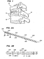
- FIG. 1 is a side view of a portion of a spine with a vertebral compression fracture.
- FIG. 2A is a side view of a flexible monolithic chain according to an embodiment of the present invention.
- FIG. 2B is a close-up cross-sectional side view of the flexible monolithic chain of FIG. 2A taken through line B-B.
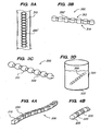
- FIGS. 3 A-D is an illustration depicting a method of fabricating a flexible monolithic chain.
- FIGS. 4A-C are perspective views of other embodiments of a flexible monolithic chain having flexible portions and non-flexible portions with substantially uniform dimensions.
- FIG. 5 is a perspective, cross-sectional view of another embodiment of a flexible monolithic chain.
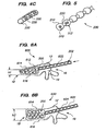
- FIGS. 6A and B are side cross-sectional views of a flexible monolithic chain being implanted within a fractured vertebral body.
- FIG. 7 is a cross-sectional top view of a flexible monolithic chain implanted within a vertebral body.
- FIG. 8A is a cross-sectional side view of a vertebra having a flexible monolithic chain implanted within a vertebral body.
- FIG. 8B is a cross-sectional side view of a vertebra having an implanted flexible monolithic chain as in FIG. 8A , showing an end of the chain extending from the vertebra.
- FIG. 8C is a cross-sectional side view of a vertebra having an implanted flexible monolithic chain as in FIG. 8A , and further including a pedicle screw implant.
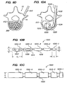
- FIGS. 9A-D are top views depicting a minimally invasive method for implanting a flexible monolithic chain within a vertebral body.
- FIG. 10A is a cross-sectional top view of another method of implanting a flexible monolithic chain within a vertebral body.
- FIGS. 10B is a top view of a flexible monolithic chain that may be used in the method of FIG. 10A .
- FIG. 10C is a side view of another embodiment of a flexible monolithic chain that may be used in the method of FIG. 10A .
- FIG. 11A is a side view of a screw device for driving a chain implant through an introducer.
- FIG. 11B is an end view of a screw device for driving a chain implant through an introducer.
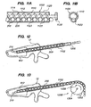
- FIG. 12 is a side view of a plunger device for driving a chain implant through an introducer.
- FIG. 13 is a side view of a sprocket device for driving a chain implant through an introducer.
- FIGS. 14A and B are cross-sectional side views of a flexible monolithic chain implanted into the head of a femur.
- FIG. 15 is a cross-sectional view of a chain implant inserted through a cannula into the head of a femur.
- a chain 200 (sometimes referred to as an elongated member) comprises one or more bodies 210 (sometimes referred to as beads).
- Chain 200 is preferably a monolithic chain, e.g., formed from a single, common material or type of material forming an integral structure.
- Bodies 210 are preferably substantially non-flexible, and may be solid, semi-solid, porous, non-porous, hollow, or any combination thereof.
- Chain 200 may also comprise one or more linking portions 220, also sometimes referred to as struts or links 220.
- Struts 220 may be disposed between each pair of adjacent bodies 210.
- Struts 220 are preferably substantially flexible or semiflexible, e.g. to allow for bending of the chain 200 between bodies 210.
- Bodies 210 of chain 200 are formed of bone, e.g., cortical bone, cancellous bone or both, but preferably cortical bone.
- chain 200 may be comprised of any biocompatible material having desired characteristics, for example a biocompatible polymer, metal, ceramic, composite or any combination thereof.
- Bodies 210 may be absorbable or resorbable by the body.
- the bodies 210 preferably have osteoinductive properties or are made at least partly from osteoinductive materials.
- the outer circumferential shape of the body may be the same as adjacent links. Alternatively or in addition, the outer circumferential shape of the body may be the same size as adjacent links.
- Bodies 210 may be of uniform or non-uniform size, shape and/or materials, and may be linked in series, for example by one or more flexible or semi-flexible linking portions 220, which can form struts of any desired length between bodies 210.
- Linking portions are preferably, although not necessarily, formed of the same material as bodies 210.
- a chain 200 may have any desired number of linked bodies 210, and may have a first end 202 and a second end 204.
- chain 200 may be formed in a loop, ring, or other configuration having no ends, or may be configured to have multiple extensions and/or multiple ends, for example like branches of a tree.
- the one or more linking portions 220 may be comprised of any biocompatible material having desired characteristics of flexibility, strength, and the like.
- linking portions 220 may be formed, at least in part, of substantially the same material as bodies 210.
- chain 200, including bodies 210 and/or linking portions 220, may be resorbable.
- the bodies 210 may be of uniform or non-uniform size, and may be spaced by linking portions 220 at uniform or non-uniform increments.
- FIG. 2B is a close up cross-sectional view of chain 200, taken at line B-B in FIG. 2A .
- chain 200 is a monolithic chain, with bodies 210 and flexible portions 220 formed from a uniform material, e.g., bone.
- bodies 210 are shown as substantially spherical, and linking portions 220 are shown as substantially cylindrical, numerous other shapes are contemplated.
- chains 200, including body 210 and/or linking portion 220 may be of any desired shape, such as for example, cylindrical, elliptical, spherical, rectangular, etc.
- Body 210 and/or linking portion 220 may also be of any particular cross sectional shape such as round hexagonal, square, etc.
- Bodies 210 and linking portions 220 may have the same or different shapes.
- the configurations of bodies 210 may vary within a chain 200, for example as described herein with respect to FIGS. 5 and 10 .
- the configuration of links 220 may vary within a chain.
- the bodies can be shaped so that they fit together to minimize interstitial spacing or provide a predetermined range of interstitial spacing.
- the diameter 230 of bodies 210 may be between about 1mm and about 15mm, preferably between about 2mm and about 8mm, or more preferably between about 4 mm and about 6 mm.
- the non-flexible bodies 210 are larger in shape and size than the flexible struts 220.
- height 232 of struts 220 may be between about 0.5 mm and about 8 mm, preferably between about 0.8 mm and about 4 mm, and may depend in part upon the size of bodies 210.
- Struts 220 may have any desired length 238, e.g., between about 0.5 mm and about 5.0 mm, preferably between about 1.5 mm and 3.5 mm, or greater than 5 mm.
- distance 234 between bodies 210 may be any desired distance, e.g., depending upon the size of bodies 210 and/or length 238 struts 220. In some embodiments, for example, distance 234 may be between about 4 mm and about 15 mm, or between about 6 mm and about 10 mm.
- the junctions between bodies 210 and struts 220 may have a radius 236 of any desired dimension, e.g., less than 1.0 mm, between about 1.0 mm and about 2.0 mm, or greater than about 2.0 mm.
- each of the bodies 210 and struts 220 of a chain may be of the same configuration and/or dimensions as other bodies 210 and struts within the chain 200.
- bodies 210 and/or struts 220 within a chain may have different configurations or dimensions.
- the non-flexible bodies 210 and flexible portions 220 may be of the same shape and size to form a relatively uniform structure, for example as shown in FIG. 4 .
- a chain 200 may be made as long as practical for a particular application.
- an exemplary chain 200 for implantation into a bone may be about 100mm in length.
- chain 200 may be of other lengths, for example less than about 1 mm, between about 1 mm and about 100 mm, or greater than 100mm.
- two or more chains 200 and/or other implants may be used in combination with each other.
- Chain 200 may be connected end to end to form larger chains.
- the present invention is preferably directed to the creation of implants from allograft material
- the present invention may also be applied to implants that utilize other materials, including but not limited to the following: xenograft, autograft, metals, alloys, ceramics, polymers, composites, and encapsulated fluids or gels.
- the implants described herein may be formed of materials with varying levels of porosity, such as by combined bone sections from different bones or different types of tissues and/or materials having varying levels of porosity.
- the implants described herein are formed of bone materials with varying mineral content.
- cancellous or cortical bone may be provided in natural, partially demineralized, or demineralized states.
- Demineralization is typically achieved with a variety of chemical processing techniques, including the use of an acid such as hydrochloric acid, chelating agents, electrolysis or other treatments.
- the demineralization treatment removes the minerals contained in the natural bone, leaving collagen fibers with bone growth factors including bone morphogenic protein (BMP). Variation in the mechanical properties of bone sections is obtainable through various amounts of demineralization.
- BMP bone morphogenic protein
- a demineralizing agent on bone transforms the properties of the bone from a stiff structure to a relatively pliable structure.
- the flexibility or pliability of demineralized bone may be enhanced when the bone is hydrated.
- Any desired portions of bone components, e.g., link portions 220 or any other desired portion may be demineralized or partially demineralized in order to achieve a desired amount of malleability, elasticity, pliability or flexibility, generally referred to herein as "flexibility".
- the amount of flexibility can be varied by varying in part the amount of demineralization.
- bone components initially may be provided with moisture content as follows: (a) bone in the natural state fresh out of the donor without freezing, (b) bone in the frozen state, typically at -40°C, with moisture content intact, (c) bone with moisture removed such as freeze-dried bone, and (d) bone in the hydrated state, such as when submersed in water.
- moisture content as follows: (a) bone in the natural state fresh out of the donor without freezing, (b) bone in the frozen state, typically at -40°C, with moisture content intact, (c) bone with moisture removed such as freeze-dried bone, and (d) bone in the hydrated state, such as when submersed in water.
- the implants may be formed entirely from cortical bone, entirely from cancellous bone, or from a combination of cortical and cancellous bone.
- the structure optionally may include perforations or through bores extending from one outer surface to another outer surface, or recesses formed in outer surfaces that do not extend through inner surfaces (surface porosity), or recesses formed internally.
- Surface texture such as depressions and/or dimples may be formed on the outer surface.
- the depressions and/or dimples may be circular, diamond, rectangular, irregular or have other shapes.
- the flexible monolithic chain devices described herein may be used to treat disease and pathological conditions in general orthopedic applications such as long bone infections, comminuted complex fractures, tumor resections and osteotomies. Additionally the device can be used to treat disease and pathological conditions in spinal applications, such as, for example, degenerative disc disease, collapsed intervertebral discs, vertebral body tumor or fractures, vertebral body resections or generally unstable vertebral bodies. In other embodiments, a flexible monolithic chain device may be used in maxillofacial applications or in non-fusion nucleus replacement procedures.
- FIG. 3 shows an example of a method 300 for fabricating a monolithic chain device 200 out of bone material 310.
- allograft femoral bone 310 is used as a base material, preferably, cortical allograft bone.
- Other bones may be used for forming implants, for example, radius, humerous, tibia, femur, fibula, ulna, ribs, pelvic, vertebrae or other bones.
- an initial step comprises machining a rough monolithic chain 200', having a desired general shape, out of the raw material 310, preferably bone.
- a desired general shape for example, conventional milling and/or other fabrication techniques may be used.
- Device 200 may have any desired shape, for example including generally elliptical or spherical bodies 210 separated by cylindrical linking portions 220 as shown.
- chain 200 may be formed of a substantially uniform shape as shown, for example, in FIG. 4 .
- the rough monolithic device 200' may then be removed from the raw material 310, as shown for example in step B.
- an upper side 312 of the rough device 200' has been fabricated to have a desired general shape as described above.
- An opposite side 314, however, may include excess material that was not removed in step A.
- opposite side 314 is machined to remove excess material, for example using conventional milling methods.
- Side 312 may also be further machined or shaped as desired, in order to form a monolithic chain device 200 having the desired shapes and configurations of bodies 210 and linking portions 220.
- the shaped chain 200, formed of bone may be demineralized, e.g., in container 320 containing a demineralizing solution 322 (e.g., hydrochloric acid) or using another method.
- Demineralization may be allowed to occur for a specified amount of time, for example to allow the smaller, lower volume portions 220 of the device 200 to become more flexible or elastic, while the larger bodies 210 of the device remain structurally intact and substantially rigid.
- the amount of time and/or the concentration or composition of the demineralizing solution may be varied to provide the desired amount of flexibility or elasticity.
- this secondary process of demineralization can be applied to specific portions of the device 200, e.g., by masking or shielding the portions that do not or should not be treated.
- the flexible portions 220 can be partially or entirely demineralized, and the non-flexible portions 210 may retain their original mineralized state prior to the masking.
- an allograft device may be submerged entirely into demineralization acid without masking any portions of the device.
- the flexible portions 220 may demineralize entirely, or at least substantially more than the larger portions 210, which may undergo only surface demineralization. Therefore, the smaller portions 220 may become flexible and elastic while the larger portions 210 may remain relatively stiff and substantially non-flexible.
- FIG. 2B shows regions 240 that are substantially demineralized and regions 242 that have substantially their natural or original composition and mineralization content.
- Table 1 provides examples of demineralization times of four monolithic chains having different strut configurations.
- Each of the chains were formed of cortical allograft bone and had body portions 210 that were approximately 5 mm in diameter.
- Configurations and dimensions of the struts 220 differed between the samples.
- the struts were fully demineralized between about 3 1 ⁇ 2 and 4 hours, while the beads were demineralized to an extent, but were not fully demineralized across their entire thickness.
- Strut dimensions correspond to distance 238 in FIG. 2B
- strut radius corresponds to radius 236 in FIG. 2B .
- Full flexibility is considered to be the condition when the chain can be bent until two adjacent beads contact each other without the chain cracking or breaking.
- Table 2 below provides an example of approximate incremental changes in flexibility of strut portions 220 of a sample, e.g., Sample 1 of Table 1, as a function of duration of exposure to the hydrochloric acid bath.
- TABLE 2 Incremental changes in flexibility of struts with exposure to acid bath. Exposure Time (min) Flexibility (% of maximum) 0-5 0 5-10 0 10-15 10 15-20 15 20-30 25 30-45 35 45-90 50 90-140 70 140-200 85 200-240 100
- Various other configurations and methods for manufacturing monolithic or other chain implants may be used. The choice of methods may depend, at least in part, on the material or materials to be used in the particular chain device 200. If the device is made of a biocompatible polymeric material, the device can be manufactured by using conventional manufacturing methods such as but not limited to milling and turning. Alternatively, if the chain device 200 is made out of a biocompatible polymeric material, the entire device can also be injection molded.
- the chain 200 is made of a metallic material, it can be manufactured by using conventional manufacturing methods such as but not limited to milling and turning.
- the flexible components may undergo secondary processes such as annealing.
- the secondary process can be limited to the flexible portions of the device only, for example by masking or shielding the non-flexible portions.
- a chain implant 200 can be formed of any type of biocompatible material that will allow for sufficient flexibility in areas of reduced material sections (e.g., relatively narrow and flexible portions 220), while having larger sections (e.g., bodies 210) that are substantially rigid and allow for load bearing characteristics.
- the reduced material portions 220 may be flexible, pliable, or have elastic properties in all directions preferably without fracturing or breaking.
- the reduced material portions 210 may allow for fracture during device 200 insertion, or at another stage in a method, to allow for proper void filling.
- Materials may be metallic and include but are not limited to titanium and steels. Polymeric and alternatively allograft tissue materials can be used.
- bone device 200 may comprise one or more other materials, e.g., a metal (titanium, a steel, or other metal), an alloy, or a polymer.
- the material of the device 200 may have osteoconductive, osteoinductive, and/or osteogenic properties.
- a chain 200 may have any desired geometric configuration.
- rigid portions 210 and flexible portions 220 may have the same or different shapes, such as cubes, cylinders, any polyhedral shapes, balls, banana or kidney shaped, or any combination thereof.
- Portions 210 and/or 220 may have any desired cross-sectional shape, such as for example rectangular, circular, elliptical, pentagonal, hexagonal, etc.
- the flexible 220 and non-flexible 210 portions may be of the same shape to form relatively uniform shaped structures as shown in FIGS. 4A-C .
- one or more bodies 210 may have cavities 510 or central holes 512. Such holes 512 or cavities 510 may be empty or may be filled, for example with a cement, bone filler, adhesive, graft material, therapeutic agent, or any other desired materials.
- the filling material may incorporate radiopaque agents so that the chain, or bodies can be visualized during and after a procedure.
- an implant device 200 may be coated with different substances that will support and promote bone healing, reduce infections and/or deliver therapeutic agents to the treated site.
- the device 200 or portions thereof may be coated with antibiotics, BMP, bone growth enhancing agents, porous or non-porous bone ingrowth agents, therapeutic agents, etc.
- the implant may be coated with a material that may incorporate a radiopaque agent so that the implant may be visualized during or after implantation.
- therapeutic agents, drug agents, BMPs, tissue growth enhancing agents, osteoinductive agents may be absorbed, sorbed or other wise perfused onto or into some portion of the chain implant.
- the solid, non-flexible portions 210 may have cavities, axial or side holes or a combination thereof that can be filled with different substances or agents.
- a minimally invasive method 600 of augmenting a damaged vertebral body 12, e.g., following a vertebral compression fracture, may comprise implanting one or more chains 200 into an inner portion 612 of a vertebral body 12 between endplates 614 and 616.
- one or more chains 200 may be implanted as a preventive measure to augment a vertebra before compression or a compression fracture.
- a hole may be formed in the outer coritcal shell of vertebral body 12 by a trocar, drill or other instrument. Chain 200 may then be implanted, for example, through a cannula 602 or other introducer inserted into vertebral body 12.
- Suitable procedures and materials for inserting a cannula through which chain 200 may be introduced are known in the art, and may be similar to those described above for kyphoplasty and other procedures.
- cannula 602 may be introduced through the posterior portion 16 of vertebral body 12, e.g., through pedicle 14 (e.g., transpedicular approach).
- a chain 200 may be inserted and may compact the cancellous and osteoporotic bone inside the vertebral body.
- a passageway may be formed into the interior of the vertebral body, for example using a drill or other instrument.
- the chain 200 may then be inserted through the passageway, and may compact or compress the bone material inside the vertebral body.
- instruments such as, for example, currettes or balloon catheter may be used to compress and compact the bone inside the vertebral body to create a cavity.
- the instruments may then be removed.
- the balloon portion of the catheter may remain within the vertebral body or may form a container for the implant.
- the cavity in the vertebral body also may be formed by removing bone material as opposed to compacting the bone.
- a reamer or other apparatus could be used to remove bone material from the inside of the vertebral body.
- a cavity is first formed in the bone structure or the chain(s) are inserted without first creating a cavity
- they may fill central portion 612 and provide structural support to stabilize a vertebral body.
- the implant, and particularly the linked bodies 210 can push against the interior or inner sides of endplates 614 and 616, thereby tending to restore vertebral body 12 from a collapsed height h1 to its original or desired treated height h2 and provide structural support to stabilize vertebral body 12.
- an instrument can be inserted through the passageway to restore the height of the vertebra and plates.
- a balloon catheter can be inserted to restore vertebra end plates, or an elongated instrument that contacts the inside of the end plates and pushes on them may be utilized.
- the flexibility of one or more portions 220 between bodies 210 may allow bending of chain within space 612, e.g., in a uniform pattern or in a non-uniform or tortuous configuration, to aid in ensuring a thorough integration of the implant 200 within the bone 12.
- the configuration of bodies 210 attached by flexible portions also may permit bending to substantially fill the cavity and/or vertebral bone so no large pockets or voids are created or remain which may result in weak spots or a weakened bone structure.
- the flexible links may also allow the chain to collapse and possibly become entangled so that it becomes larger than its insertion hole so that it cannon be easily ejected.
- chain 200 may be inserted into a bone such as a vertebral body 12, e.g., through the lumen 604 of a cannula 602 or other sheath, and such sheath may be removed after implantation within the bone 12.
- chain 200, or a portion thereof may remain in vertebral body 12, for example, to continue augmenting the vertebra and maintain proper lordosis.
- PMMA or another bone cement or filler may be inserted sequentially or simultaneously into vertebral body 12, e.g., through shaft and/or a cannula 602, along with bodies 210 to further enhance fixation or repair of the damaged region.
- a plug of bone cement may be inserted into the hole that was initially formed to insert chains 200 (e.g., plug 812 of FIG. 8A ).
- the plug may cover the insertion hole to prevent the implant (chains) from being removed or ejected.
- some or all of bodies 210 of chain 200 may be removed after repositioning the bone, and PMMA or another bone cement or filler may be injected into a void created by chain 200.
- a bone growth promoting filler may be inserted into vertebral body 12 and a plug of bone cement utilized to hold the linked bodies and filler material in the vertebrae.
- flexible chain 200 may be coated with an adhesive, such that chain 200 may be inserted into vertebral body 12 in a flexible state and may become tangled and/or convoluted during or after insertion. After insertion, bodies 210 may become attached together by the adhesive so that the flexible chain becomes a mass that may be locked into the vertebral body, or otherwise secured such that chain 200 may not be easily removed through the insertion opening.
- linked bodies 210 may be coated with an adhesive and chain may be inserted, with or without becoming tangled or convoluted, into a vertebral body.
- a portion of chain 200 may be exposed to an energy source (e.g., an ultraviolet light, ultrasonic radiation, radio waves, heat, electric filed, magnetic field), for example to activate the adhesive, such that the exposed portion of chain 200 becomes joined to form a mass, or becomes rigid, or both, thereby further augmenting the vertebral body 12 and/or preventing removal or ejection of chain 200 through the insertion opening.
- an energy source e.g., an ultraviolet light, ultrasonic radiation, radio waves, heat, electric filed, magnetic field
- FIG. 7 is a top cross-sectional view illustration of a vertebral body 12 having one or more chains 200 implanted within portion 612 of vertebral body 12.
- the one or more chains 200 may comprise a plurality of bodies 210, which may be joined in series by one or more linking portions as described above.
- One or more cannulae 602, each for example having a lumen 604 of sufficient size for passing linked bodies 210, can be used to implant chain 200 into vertebral body.
- the one or more cannulae 602 may be inserted into vertebral body 12, preferably through pedicles 14.
- the one or more cannulae 602 may be left within vertebral body 12, and remain extending from pedicles, 14, for example held in place by sutures (not shown).
- chains 200 may be implanted completely within vertebral body 12 as shown in FIG. 8A , and the cannulae or other introducer may be removed. The chains may remain entirely within the interior of the bone.
- a passageway 810 through which chains 200 were inserted may be filled with a plug 812, e.g., a bone cement plug.
- a plug 812 e.g., a bone cement plug.
- an end 204 of chain 200 may be left extending through the insertion hole of the bone, for example through the pedicle 14 of vertebra 12.
- other implants or apparatus such as for example a bone screw 800, may be inserted into vertebral body 12 in conjunction with chain implant 200 to further augment vertebral body 12.
- the extended end 204 or additional implant 800 may be used, for example, as an anchoring element for imparting an eternal force on vertebra to reposition the vertebra 12.
- Screw 800 may be inserted into the opening used to insert the chains, and may further serve as a plug to prevent removal or ejection of the chains.
- Screw 800 may be hollow or solid, and may be comprised of stainless steel, a metal alloy, a ceramic, polymer, composite or any other desired material.
- screw 800 may be hollow, e.g., including a lumen such as lumen 604 of cannula 602, and used as an introducer to create a passage for passing chain 200 into vertebral body 12.
- a bone cement or other material may be injected into vertebral body 12 to further secure implants 200 and/or 800 and augment vertebral body 12. The bone cement or other material may be inserted through the cannulation of the screw.
- FIGS. 9A-D show another example of a flexible monolithic chain device being implanted into vertebral body
- a chain device 200 after a chain device 200 is unpacked, e.g., from a sterile package or container, it may be placed into an introducer or delivery device 910 that aids in insertion and/or impaction of the chain 200 to a desired cavity, void, space or interior of a bone.
- delivery device 910 has an elongated cannula-like shaft 912 having a lumen through which chain 200 may pass.
- Device may have a funnel 914 or other structure to facilitate loading of the chain 200 and/or for holding a portion of the chain 200 prior to implantation.
- An insertion end 916 of the insertion device 910 may have a tip 918, which may be blunt, pointed, tapered or otherwise configured as desired to facilitate insertion of end 916 into a bone or other structure.
- FIG. 9B shows end 916 of insertion device 910 being inserted through pedicle 14 of vertebra 12, such that tip 918 enters interior portion 612 of the vertebral body.
- An access hole may be formed in the outer cortical shell of the vertebral body by a trocar, drill or other instrument to provide a passage through which introducer 910 device may be inserted.
- chain 200 After insertion of end 916 of delivery device 910 into the desired region, e.g., into a vertebral body 12, preferably through a pedicle, chain 200 may be inserted.
- FIG. 9C shows first end 202 of a chain 200 being inserted through the introducer 910 into space 612 of vertebral body 12.
- Chain 200 may be forced into vertebral body 12, for example by manually applying an axial force from opposite end 204 of chain 200 to drive chain 200 through introducer 910.
- a displacement member, sprocket, screw mechanism, or other device is used to apply an axial force for implanting chain 200, for example as described below with respect to FIGS. 11-13 .
- one long flexible monolithic device 200 may be inserted and impacted into the surgical site.
- multiple shorter or different chain devices 200 and/or other implants can be impacted or otherwise inserted into the desired cavity, void or space.
- the multiple shorter chain devices may be attached to each other sequentially end to end as they are inserted. In this manner as one chain is almost inserted, and with an end extending out of the patient, the leading end of the next chain is attached to the chain that is partially inserted.
- FIG. 9D shows the one or more chains 200 completely inserted into the central portion 612 of vertebral body 12.
- a chain or other implant 200 may compact the cancellous and/or osteoporotic bone inside a collapsed vertebral body during insertion into the vertebral body.
- a tool such as, for example, currettes or balloon catheter may be used to compress and compact the bone inside the vertebral body to create a cavity.
- the cavity in the vertebral body also may be formed by removing bone material as opposed to compacting the bone.
- a reamer or other apparatus could be used to remove bone material from the inside of the vertebral body.
- PMMA or another bone cement or filler may be inserted into vertebral body 12, e.g., through the introducer 910 or another cannula, sheath, syringe or other introducer, simultaneously with implant 200 to further enhance fixation or repair of a damaged region.
- the PMMA, bone cement or filler may be inserted into the interior of the bone after the chains (or portions thereof) have been inserted into the interior of the bone.
- a bone growth promoting filler may be inserted into the vertebral body, and a plug of bone cement may be utilized to hold the implant 200 and filler material in the vertebrae 12. In this manner, the plug of cement is not inserted into the interior of the bone, but covers the opening created in the bone to insert the implant.
- FIGS. 10A-C A minimally invasive system for fusion or non-fusion implants and insertion instruments is shown in FIGS. 10A-C .
- a flexible monolithic chain device 1000 device may be inserted into a vertebral body 12, e.g., through a cannula 1030 or other introducer inserted through a pedicle 14 as shown in FIG. 10A .
- a guide or other tool 1032 having a curved or otherwise configured tip 1034 may also be inserted through the cannula 1030 and serve to distract the end plates of the vertebral body 12 and/or guide the bodies 1010 of chain 1000 in a desired direction.
- flexible portions 1020 of chain 1000 may bend or flex to allow chain 1000 to curve or otherwise convolute in a desired fashion to fill the central portion 612.
- the flexible portions allow the implant to fold and collapse upon itself to substantially fill the interior of the bone preferably with minimal porosity or open spaces.
- chain 1000 may have flexible portions, or struts, 1020 and non-flexible portions 1010 of different shapes.
- flexible joints 1010 may be narrower than the non-flexible portions 1020, which may be kidney shaped, rectangular, or any other shape.
- Some of the non-flexible bodies may be a different size or shape than others, for example they may increase in size from a first non-flexible body 1010-1 having a width Y 1 to a last non-flexible body 1010-5 having a width Y 2 that is larger than width Y 1 .
- FIG. 10 in the exemplary embodiment of FIG.
- width Y1 may be between about 5mm and about 2mm or less, and width Y2 may be between about 6mm and about 8mm or less.
- body 1010-1 may have a length X 1 that is substantially shorter than the length X 2 of body 1010-5.
- length X 1 may be between about 2mm and about 6mm
- length X 2 may be between about 6mm and about 14mm.
- Overall length of chain 1000 may vary depending upon the desired application, for example from about 10mm to about 150mm, more preferably from about 40mm to about 100mm. Of course various other sizes and relative differences in size or configuration of width, circumference, shape, curvature, or other dimensions of bodies 1010 and/or flexible portions 1020 may be employed without departing from the scope of the present invention.
- one or more of the bodies 1010 may have one or more openings or cavities 1012 or 1014.
- Such openings or cavities 1012, 1014 may be empty or may be filled, for example with a cement, bone filler, adhesive, graft material, therapeutic agent, or any other desired materials.
- an implant device 1000 may be coated with different substances that will support and promote bone healing, reduce infections and/or deliver therapeutic agents to the treated site.
- the non-flexible or flexible portions may also have porous surfaces 1016, for example to facilitate in growth of bone or other tissues.
- FIG. 10C shows another embodiment of a chain 1050, having substantially rectangular or cylindrical bodies 1010-1; 1010-2, 1010-3, 1010-4 and 1010-5, which may be separated by flexible link portions 1020, and may have the same or different dimensions as each other.
- all of the bodies 1010-1, 1010-2, 1010-3, 1010-4 and 1010-5 have the same height h but different lengths.
- the struts 1020 in FIG. 10C have a different smaller height than the bodies 1010.
- FIG. 11 is a side view illustration of an insertion device 1100 for implanting a chain 200 into a bone or other desired structure.
- insertion device 110 may include an insertion tube or cannula 1120 having a wall 1122 and a lumen 1223. Disposed within and extending through at least a portion of lumen 1223 is a rotatable screw mechanism 1110 having spiral threads 1114 surrounding an axial shaft 1112. Threads 1114 preferably extend from shaft and are dimensioned and spaced to engage chain 200, e.g., between bodies 210.
- Such an insertion device may allow for enhanced insertion force of an implant, for example in order to move vertebral endplates to restore the height of the end plates of a vertebra, to compress cancellous bone in a region of the implant, or to otherwise force the implant into a desired area.
- FIGS. 12 and 13 show other mechanisms for forcing a chain 200 through an introducer and into a desired region.
- FIG. 12 shows a plunger, pusher or other displacement member 1200 inserted within cannula 1102.
- Displacement member 1200 may be used to displace or push bodies 210 of chain through cannula 1102 and into vertebral body 12.
- Displacement member 1200 may be driven, for example, by pressure, e.g., from a syringe, rod, or other apparatus that forces displacement member 1200 into cannula 1102 and towards vertebral body 12.
- pressure e.g., from a syringe, rod, or other apparatus that forces displacement member 1200 into cannula 1102 and towards vertebral body 12.
- a sprocket 1300 or apparatus that may be wheel-like and have teeth, gears or other extensions 1302 may be configured to engage bodies 210 of chain 200.
- Sprocket 1300 rotates about a central axis 1304, for example in a direction shown by arrow 1306, teeth 1302 may engage bodies 210 and force chain 200 through cannula 1102 and into portion 612 of vertebral body 12.
- sprocket 1300 may be rotated in an opposite direction to remove some or all of chain 200, for example after restoring a height of vertebral body 12.
- the flexible monolithic chain devices and/or methods described herein may be used in conjunction with or instead of other methods or devices for augmenting vertebral bodies or other bones, such as, for example are described in United States Provisional Patent Application No. 60/722,064, filed September 28, 2005 entitled “Apparatus and Methods for Vertebral Augmentation using Linked Bodies”.
- an implantable monolithic chain 200 may be used to augment vertebrae where a compression or a compression fracture has not yet occurred and thus can be preventative in nature.
- the chain can be used in-between two vertebra.
- the chain implant can be inserted in the annulus of a spinal disc, or the disc can be removed and the chain implant inserted in-between adjacent vertebra to promote fusion of adjacent vertebrae.
- the chain implant in some embodiments may be insertable in an additional implant, such as a cage implanted in-between adjacent vertebrae.
- the chain implant may also be used to reposition and/or augment other damaged bone regions such as a fractured or weakened proximal femur 1400 as shown in FIG. 14 .
- one or more chains 200 may be inserted into a head 1410 of femur 1400, e.g., through a cannula 1102 or other introducer as show in FIG. 15 . Once inserted, chain 200 may compact material within head 1410 and provide solid support to augment the head 1410. A bone cement or other filler may also be used to aid augmentation.
- another implant 1420 may be inserted in addition to or instead of one or more chains 200.
- the implants and methods described herein may be used in conjunction with other apparatus and methods to restore lordosis and augment the vertebral body.
- one or more chains 200 may be used in conjunction with known procedures, e.g., a balloon kyphoplasty, that may be used to begin repositioning of a vertebral body and/or create a space within the body for chain 200.
- one or more chains 200 may be used in conjunction with other tools or external fixation apparatus for helping to manipulate or fix the vertebrae or other bones in a desired position.
- kits comprises various combinations of assemblies and components.
- a kit may include, for example, a cannula or other introducer and one or more flexible monolithic chains 200.
- the one or more chains 200 may be provided in different sizes, e.g., different lengths and/or diameters.
- a kit may include an introducer, one or more chains, and a syringe or other apparatus for injecting a cement or other filler into a vertebral body or other space.
- a kit may comprise one or more balloon catheters, curettes, and other instruments and may additionally include anchoring elements, tensioning members, fixation members, or any combination thereof, for example as described in United States Provisional Patent Application No.
- various minimally invasive implants and methods for alleviating discomfort associated with the spinal column may employ anchors and other implants described herein.
- a monolithic chain implant within an expandable container may be implanted between spinous processes of adjacent vertebrae to distract the processes and alleviate pain and other problems caused for example by spinal stenosis, facet arthropathy, and the like.
- augmentation systems described herein may be used instead of or in addition to expandable interspinous process apparatus and methods described in U.S. Patent Publication number 2004/018128 and U.S. Patent Application 6,419,676 to Zucherman et al.
- a cannula may be inserted laterally between adjacent spinous processes to insert a container that may be filled with the flexible chains and expand the container and thus keep the adjacent spinous processes at the desired distance.
- a balloon container, with a deflatable balloon portion can be inserted laterally through adjacent spinous processes and filled with the flexible chains to expand the balloon to a desired size to hold adjacent spinous processes at a desired distances. The balloon can thereafter be sealed and detached from the catheter.
- Other materials may be inserted within the balloon volume to supplement flexible bodies.
Abstract
Description
- The invention relates to implants, and more particularly to flexible chain implants for augmenting or supporting bones or other structures, such as, for example vertebral discs.
- Vertebral compression fractures, as illustrated in
FIG. 1 , represent a generally common spinal injury and may result in prolonged disability. These fractures involve collapsing of one or morevertebral bodies 12 in thespine 10. Compression fractures of the spine usually occur in the lower vertebrae of the thoracic spine or the upper vertebra of the lumbar spine. They generally involve fracture of theanterior portion 18 of the affected vertebra 12 (as opposed to the posterior side 16). Spinal compression fractures can result in deformation of the normal alignment or curvature, e.g., lordosis, of vertebral bodies in the affected area of the spine. Spinal compression fractures and/or related spinal deformities can result, for example, from metastatic diseases of the spine, from trauma or can be associated with osteoporosis. Until recently, doctors were limited in how they could treat such compression fractures and related deformities. Pain medications, bed rest, bracing or invasive spinal surgery were the only options available. - More recently, minimally invasive surgical procedures for treating vertebral compression fractures have been developed. These procedures generally involve the use of a cannula or other access tool inserted into the posterior of the effected vertebral body, usually through the pedicles. The most basic of these procedures is vertebroplasty, which literally means fixing the vertebral body, and may be done without first repositioning the bone.
- Briefly, a cannula or special bone needle is passed slowly through the soft tissues of the back. Image guided x-ray, along with a small amount of x-ray dye, allows the position of the needle to be seen at all times. A small amount of polymethylmethacrylate (PMMA) or other orthopedic cement is pushed through the needle into the vertebral body. PMMA is a medical grade substance that has been used for many years in a variety of orthopedic procedures. Generally, the cement is mixed with an antibiotic to reduce the risk of infection, and a powder containing barium or tantalum, which allows it to be seen on the X-ray.
- Vertebroplasty can be effective in the reduction or elimination of fracture pain, prevention of further collapse, and a return to mobility in patients. However, this procedure may not reposition the fractured bone and therefore may not address the problem of spinal deformity due to the fracture. It generally is not performed except in situations where the kyphosis between adjacent vertebral bodies in the effected area is less than 10 percent. Moreover, this procedure requires high-pressure cement injection using low-viscosity cement, and may lead to cement leaks in 30-80% of procedures, according to recent studies. In most cases, the cement leakage does no harm. In rare cases, however, polymethymethacrylate or other cement leaks into the spinal canal or the perivertebral venous system and causes pulmonary embolism, resulting in death of the patient.
- More advanced treatments for vertebral compression fractures generally involve two phases: (1) reposition, or restoration of the original height of the vertebral body and consequent lordotic correction of the spinal curvature; and (2) augmentation, or addition of material to support or strengthen the fractured or collapsed bone.
- One such treatment, balloon kyphoplasty (Kyphon, Inc.), is disclosed in
U.S. Patent Nos. 6,423,083 ,6,248,110 , and6,235,043 to Riley et al. A catheter having an expandable balloon tip is inserted through a cannula, sheath or other introducer into a central portion of a fractured vertebral body comprising relatively soft cancellous bone surrounded by fractured cortical bone. Kyphoplasty then achieves the reconstruction of the lordosis, or normal curvature, by inflating the balloon, which expands within the vertebral body restoring it to its original height. The balloon is removed, leaving a void within the vertebral body, and PMMA or other filler material is then injected through the cannula into the void as described above with respect to vertebroplasty. The cannula is removed and the cement cures to augment, fill or fix the bone. - Disadvantages of this procedure include the high cost, the repositioning of the endplates of the vertebral body may be lost after the removal of the balloon catheter, and the possible perforation of the vertebral endplates during the procedure. As with vertebroplasty, perhaps the most feared, albeit remote, complications concerning kyphoplasty are related to leakage of bone cement. For example, a neurologic deficit, may occur through leakage of bone cement into the spinal canal. Such a cement leak may occur through the low resistance veins of the vertebral body or through a crack in the bone which was not appreciated previously. Other complications include additional adjacent level vertebral fractures, infection and cement embolization. Cement embolization occurs by a similar mechanism to a cement leak. The cement may be forced into the low resistance venous system and travel to the lungs or brain resulting in a pulmonary embolism or stroke.
- Another approach for treating vertebral compression fractures is the Optimesh system (Spineology, Inc., Stillwater, MN), which provides minimally invasive delivery of a cement or allograft or autograft bone using an expandable mesh graft balloon, or containment device, within the involved vertebral body. The balloon graft remains inside the vertebral body after its inflation, which prevents an intraoperative loss of reposition, such as can occur during a kyphoplasty procedure when the balloon is withdrawn. One drawback of this system, however, is that the mesh implant is not well integrated in the vertebral body. This can lead to relative motion between the implant and vertebral body, and consequently to a postoperative loss of reposition. Additional details regarding this procedure may be found, for example, in published
U.S. Patent Publication Number 20040073308 . DocumentUS 2005278023 A discloses an apparatus according to the preamble of claim 1. - Still another procedure used in the treatment of vertebral compression fractures is an inflatable polymer augmentation mass known as a SKy Bone Expander. This device can be expanded up to a pre-designed size and (Cubic or Trapezoid) configuration in a controlled manner. Like the Kyphon balloon, once optimal vertebra height and void are achieved, the SKy Bone Expander is removed and PMMA cement or other filler is injected into the void. This procedure therefore entails many of the same drawbacks and deficiencies described above with respect to kyphoplasty.
- In some cases of fractured or otherwise damaged bones, bone grafts are used to repair or otherwise treat the damaged area. In the United States alone, approximately half a million bone grafting procedures are performed annually, directed to a diverse array of medical interventions for complications such as fractures involving bone loss, injuries or other conditions necessitating immobilization by fusion (such as for the spine or joints), and other bone defects that may be present due to trauma, infection, or disease. Bone grafting involves the surgical transplantation of pieces of bone within the body, and generally is effectuated through the use of graft material acquired from a human source. This is primarily due to the limited applicability of xenografts, transplants from another species.
- Orthopedic autografts or autogenous grafts involve source bone acquired from the same individual that will receive the transplantation. Thus, this type of transplant moves bony material from one location in a body to another location in the same body, and has the advantage of producing minimal immunological complications. It is not always possible or even desirable to use an autograft. The acquisition of bone material from the body of a patient typically requires a separate operation from the implantation procedure. Furthermore, the removal of material, oftentimes involving the use of healthy material from the pelvic area or ribs, has the tendency to result in additional patient discomfort during rehabilitation, particularly at the location of the material removal. Grafts formed from synthetic material have also been developed, but the difficulty in mimicking the properties of bone limits the efficacy of these implants.
- As a result of the challenges posed by autografts and synthetic grafts, many orthopedic procedures alternatively involve the use of allografts, which are bone grafts from other human sources (normally cadavers). The bone grafts, for example, are placed in a host bone and serve as the substructure for supporting new bone tissue growth from the host bone. The grafts are sculpted to assume a shape that is appropriate for insertion at the fracture or defect area, and often require fixation to that area for example by screws, pins, cement, cages, membranes, etc. Due to the availability of allograft source material, and the widespread acceptance of this material in the medical community, the use of allograft tissues is likely to expand in the field of musculoskeletal surgery.
- Notably, the various bones of the body such as the femur (thigh), tibia and fibula (leg), humerus (upper arm), radius and ulna (lower arm) have geometries that vary considerably. In addition, the lengths of these bones vary; for example, in an adult the lengths may vary from 47 centimeters (femur) to 26 centimeters (radius). Furthermore, the shape of the cross section of each type of bone varies considerably, as does the shape of any given bone over its length. While a femur has a generally rounded outer shape, a tibia has a generally triangular outer shape. Also, the wall thickness varies in different areas of the cross-section of each bone. Thus, the use of any given bone to produce an implant component may be a function of the bone's dimensions and geometry. Machining of bones, however, may permit the production of implant components with standardized or custom dimensions.
- As a collagen-rich and mineralized tissue, bone is composed of about forty percent organic material (mainly collagen), with the remainder being inorganic material (mainly a near-hydroxyapatite composition resembling 3Ca3(PO4)2Ca(OH)2). Structurally, the collagen assumes a fibril formation, with hydroxyapatite crystals disposed along the length of the fibril, and the individual fibrils are disposed parallel to each other forming fibers. Depending on the type of bone, the fibrils are either interwoven, or arranged in lamellae that are disposed perpendicular to each other.
- Bone tissues have a complex design, and there are substantial variations in the properties of bone tissues depending upon the type of bone (i.e., leg, arm, vertebra) as well as the overall structure. For example, when tested in the longitudinal direction, leg and arm bones have a modulus of elasticity of about 17 to 19 GPa, while vertebra tissue has a modulus of elasticity of less than 1 GPa. The tensile strength of leg and arm bones varies between about 120 MPa and about 150 MPa, while vertebra have a tensile strength of less than 4 MPa. Notably, the compressive strength of bone varies, with the femur and humerus each having a maximum compressive strength of about 167 MPa and 132 MPa respectively. Again, the vertebra have a far lower compressive strength usually of no more than about 10 MPa.
- With respect to the overall structure of a given bone, the mechanical properties vary throughout the bone. For example, a long bone (leg bone) such as the femur has both compact bone and spongy bone. Cortical bone, the compact and dense bone that surrounds the marrow cavity, is generally solid and thus carries the majority of the load in major bones. Cancellous bone, the spongy inner bone, is generally porous and ductile, and when compared to cortical bone is only about one-third to one-quarter as dense, one-tenth to one-twentieth as stiff, but five times as ductile. While cancellous bone has a tensile strength of about 10-20 MPa and a density of about 0.7 g/cm3, cortical bone has a tensile strength of about 100-200 MPa and a density of about 2 g/cm3. Additionally, the strain to failure of cancellous bone is about 5-7%, while cortical bone can only withstand 1-3% strain before failure. It should also be noted that these mechanical characteristics may degrade as a result of numerous factors such as any chemical treatment applied to the bone material, and the manner of storage after removal but prior to implantation (i.e. drying of the bone).
- Notably, implants of cancellous bone incorporate more readily with the surrounding host bone, due to the superior osteoconductive nature of cancellous bone as compared to cortical bone. Furthermore, cancellous bone from different regions of the body is known to have a range of porosities. For example, cancellous bone in the iliac crest has a different porosity than cancellous bone in a femoral head. Thus, the design of an implant using cancellous bone may be tailored to specifically incorporate material of a desired porosity.
- There remains a need in the art to provide safe and effective devices and methods for augmentation of fractured or otherwise damaged vertebrae and other bones, preferably devices that may be implanted utilizing minimally invasive methods of implantation.
- A flexible chain according to one embodiment comprises a series or other plurality of preferably solid, substantially non-flexible body portions (also referred to as bodies or beads) and a series of flexible link portions (also referred to as links or struts). The preferably solid, substantially non-flexible body portions preferably are capable of withstanding loads that are applied in any direction, and the flexible link portions of the implant preferably are disposed between the substantially non-flexible body portions and preferably are flexible in any direction, although they may be flexible in only selected or desired directions. The bodies may be substantially solid, semi-solid or hollow and preferable of sufficient strength to support the loads typical for the body location in which they are implanted. The link portions may be solid, semi-solid, or hollow and preferably of sufficient flexibility to allow the adjacent bodies to touch one another upon bending of the elongate member or chain. The material of both portions, the flexible link and non-flexible body portions, is the same and form one single, flexible monolithic chain (FMC).
- In one aspect of the invention, an apparatus for augmentation of body tissue, for example bone, comprises a flexible elongated member, or chain, having a longitudinal length substantially larger than its height or its width. The flexible elongated member comprises a plurality of substantially non-flexible bodies and a plurality of substantially flexible links interconnecting the bodies. The bodies and links are connected end-to-end to form the elongated member, wherein the elongated member is formed of a biocompatible material.
- The bodies may be different sizes and shapes than the links or they may be the same shape, same size, or both. In addition, each body and link may be a different size and shape than other bodies or links. In one embodiment, the beads can be shaped so that they can fit together to minimize interstial spaces. For example, the beads may be shaped as cubes or other polyhedrals that can be stacked together in such a way that there is little space between beads, or a predetermined percentage range of interstial space.
- The elongated member is formed as an integral monolithic chain, formed of bone, such as, for example, allograft bone. The flexible links are formed of bone that has been demineralized to a greater extent than the bodies. Optionally, a coating may be applied to at least a portion of the elongated member, e.g. a coating comprising a therapeutic agent, a bone cement, an antibiotic, a bone growth stimulating substance, bone morphogenic protein (BMP) or any combination thereof. Therapeutic agents, or drug agents (e.g., antibodies), or biologics (e.g., one or more BMPs) can be coated, or attached via peptides, adsorbed, sorbed or in some other way perfused onto or into the elongated member; either the bodies, the links or both. In some embodiments, the coating may comprise a bone cement that may be activated upon insertion into the bone. In other embodiments, at least a portion of the bodies comprise an outer surface configured to promote bone in-growth.
- In another aspect, a flexible chain implant may be impacted or inserted into a cavity, void or hollow space, e.g., through a small narrow opening. Such cavities may be, for example, voids in long bones, intervertebral disc spaces or vertebral bodies. Such voids may have occurred due to infections, disease, trauma fractures, degenerative disc disease process, tumors or osteotomies. In other embodiments, a void may be created by using a tool to compact or remove cancellous or cortical bone or other tissue prior to implantation. The chain may thereafter be implanted to fill the created void. Depending on the insertion or impaction force and depending on the amount or the length of chain devices inserted, the device will fill and/or support the tissue structure, preferably bone structure to a restored size and/or height. In an alternative embodiment, no void or cavity may be present, and even if a void or cavity is present the chain implant or elongated member may be inserted and/or implanted in a manner to compact the material and bone cells within the bone and to further fill the bone in a manner that it can better support a load and preferably fill the bone in a manner to restore its original and/or treated size and height.
- In another aspect, one or more flexible monolithic chains may be implanted into diseased, damaged or otherwise abnormal bones to treat, for example, long bone infections, comminuted complex fractures, tumor resections and osteotomies. An FMC device may also be used to treat disease or abnormal pathology conditions in spinal applications, including, for example, degenerative disc disease, collapsed intervertebral discs, vertebral body tumor or fractures, and vertebral body resections. The elongated member or chain device can be used as a preventive measure to augment a bone, spinal disc or an implant, e.g., and intervertebral body implant to promote fusion. The elongated member may be used within a vertebra or between two vertebra. The elongated member or chain also may be used for example in an intervertebral body fusion procedure, for example, as an implant inserted into the disc space between two vertebra, as an implant inserted into and retained by the disc annulus, or in combination with an additional implant inserted in the disc space between two vertebra.
- In another embodiment, a kit comprises various combinations of assemblies and components according to the present invention. A kit may include, for example, a package or container comprising an elongated member, for example an FMC device, and a cannula or other introducer or device for implanting the elongated member. In other embodiments, a kit may comprise instruments to create a cavity (e.g., balloon catheter), an FMC device and a cement or other filler material and/or a syringe or other apparatus for injecting a FMC device and/or such filler material into a vertebral body.
- The present invention can be better understood by reference to the following drawings, wherein like references numerals represent like elements. The drawings are merely exemplary to illustrate certain features that may be used singularly or in combination with other features and the present invention should not be limited to the embodiments shown.
-
FIG. 1 is a side view of a portion of a spine with a vertebral compression fracture. -
FIG. 2A is a side view of a flexible monolithic chain according to an embodiment of the present invention. -
FIG. 2B is a close-up cross-sectional side view of the flexible monolithic chain ofFIG. 2A taken through line B-B. -
FIGS. 3 A-D is an illustration depicting a method of fabricating a flexible monolithic chain. -
FIGS. 4A-C are perspective views of other embodiments of a flexible monolithic chain having flexible portions and non-flexible portions with substantially uniform dimensions. -
FIG. 5 is a perspective, cross-sectional view of another embodiment of a flexible monolithic chain. -
FIGS. 6A and B are side cross-sectional views of a flexible monolithic chain being implanted within a fractured vertebral body. -
FIG. 7 is a cross-sectional top view of a flexible monolithic chain implanted within a vertebral body. -
FIG. 8A is a cross-sectional side view of a vertebra having a flexible monolithic chain implanted within a vertebral body. -
FIG. 8B is a cross-sectional side view of a vertebra having an implanted flexible monolithic chain as inFIG. 8A , showing an end of the chain extending from the vertebra. -
FIG. 8C is a cross-sectional side view of a vertebra having an implanted flexible monolithic chain as inFIG. 8A , and further including a pedicle screw implant. -
FIGS. 9A-D are top views depicting a minimally invasive method for implanting a flexible monolithic chain within a vertebral body. -
FIG. 10A is a cross-sectional top view of another method of implanting a flexible monolithic chain within a vertebral body. -
FIGS. 10B . is a top view of a flexible monolithic chain that may be used in the method ofFIG. 10A . -
FIG. 10C is a side view of another embodiment of a flexible monolithic chain that may be used in the method ofFIG. 10A . -
FIG. 11A is a side view of a screw device for driving a chain implant through an introducer. -
FIG. 11B is an end view of a screw device for driving a chain implant through an introducer. -
FIG. 12 is a side view of a plunger device for driving a chain implant through an introducer. -
FIG. 13 is a side view of a sprocket device for driving a chain implant through an introducer. -
FIGS. 14A and B are cross-sectional side views of a flexible monolithic chain implanted into the head of a femur. -
FIG. 15 is a cross-sectional view of a chain implant inserted through a cannula into the head of a femur. - Referring to
FIG. 2 , a chain 200 (sometimes referred to as an elongated member) comprises one or more bodies 210 (sometimes referred to as beads).Chain 200 is preferably a monolithic chain, e.g., formed from a single, common material or type of material forming an integral structure.Bodies 210 are preferably substantially non-flexible, and may be solid, semi-solid, porous, non-porous, hollow, or any combination thereof.Chain 200 may also comprise one or more linkingportions 220, also sometimes referred to as struts or links 220.Struts 220 may be disposed between each pair ofadjacent bodies 210.Struts 220 are preferably substantially flexible or semiflexible, e.g. to allow for bending of thechain 200 betweenbodies 210. -
Bodies 210 ofchain 200 are formed of bone, e.g., cortical bone, cancellous bone or both, but preferably cortical bone. In other embodiments,chain 200 may be comprised of any biocompatible material having desired characteristics, for example a biocompatible polymer, metal, ceramic, composite or any combination thereof.Bodies 210 may be absorbable or resorbable by the body. For some applications, thebodies 210 preferably have osteoinductive properties or are made at least partly from osteoinductive materials. The outer circumferential shape of the body may be the same as adjacent links. Alternatively or in addition, the outer circumferential shape of the body may be the same size as adjacent links.Bodies 210 may be of uniform or non-uniform size, shape and/or materials, and may be linked in series, for example by one or more flexible orsemi-flexible linking portions 220, which can form struts of any desired length betweenbodies 210. Linking portions are preferably, although not necessarily, formed of the same material asbodies 210. - A
chain 200 may have any desired number of linkedbodies 210, and may have afirst end 202 and asecond end 204. In other embodiments,chain 200 may be formed in a loop, ring, or other configuration having no ends, or may be configured to have multiple extensions and/or multiple ends, for example like branches of a tree. - The one or more linking
portions 220 may be comprised of any biocompatible material having desired characteristics of flexibility, strength, and the like. In preferred embodiments, linkingportions 220 may be formed, at least in part, of substantially the same material asbodies 210. In some embodiments,chain 200, includingbodies 210 and/or linkingportions 220, may be resorbable. Thebodies 210 may be of uniform or non-uniform size, and may be spaced by linkingportions 220 at uniform or non-uniform increments. -
FIG. 2B is a close up cross-sectional view ofchain 200, taken at line B-B inFIG. 2A . In this example,chain 200 is a monolithic chain, withbodies 210 andflexible portions 220 formed from a uniform material, e.g., bone. Althoughbodies 210 are shown as substantially spherical, and linkingportions 220 are shown as substantially cylindrical, numerous other shapes are contemplated. In fact,chains 200, includingbody 210 and/or linkingportion 220, may be of any desired shape, such as for example, cylindrical, elliptical, spherical, rectangular, etc.Body 210 and/or linkingportion 220 may also be of any particular cross sectional shape such as round hexagonal, square, etc.Bodies 210 and linkingportions 220 may have the same or different shapes. In certain embodiments the configurations ofbodies 210 may vary within achain 200, for example as described herein with respect toFIGS. 5 and10 . Alternatively or in addition thereto, the configuration oflinks 220 may vary within a chain. In one embodiment, the bodies can be shaped so that they fit together to minimize interstitial spacing or provide a predetermined range of interstitial spacing. - All dimensional aspects of the
chain 200 can be made to fit any particular anatomy or delivery device. For example, for applications of vertebral body augmentation, thediameter 230 ofbodies 210, e.g., as shown inFIG. 2B , may be between about 1mm and about 15mm, preferably between about 2mm and about 8mm, or more preferably between about 4 mm and about 6 mm. Preferably, thenon-flexible bodies 210 are larger in shape and size than theflexible struts 220. For example,height 232 ofstruts 220 may be between about 0.5 mm and about 8 mm, preferably between about 0.8 mm and about 4 mm, and may depend in part upon the size ofbodies 210.Struts 220 may have any desiredlength 238, e.g., between about 0.5 mm and about 5.0 mm, preferably between about 1.5 mm and 3.5 mm, or greater than 5 mm. Similarly, distance 234 betweenbodies 210 may be any desired distance, e.g., depending upon the size ofbodies 210 and/orlength 238 struts 220. In some embodiments, for example, distance 234 may be between about 4 mm and about 15 mm, or between about 6 mm and about 10 mm. The junctions betweenbodies 210 and struts 220 may have aradius 236 of any desired dimension, e.g., less than 1.0 mm, between about 1.0 mm and about 2.0 mm, or greater than about 2.0 mm. - In some embodiments, each of the
bodies 210 and struts 220 of a chain may be of the same configuration and/or dimensions asother bodies 210 and struts within thechain 200. In other embodiments,bodies 210 and/or struts 220 within a chain may have different configurations or dimensions. In still other embodiments, thenon-flexible bodies 210 andflexible portions 220 may be of the same shape and size to form a relatively uniform structure, for example as shown inFIG. 4 . - A
chain 200 may be made as long as practical for a particular application. For example, anexemplary chain 200 for implantation into a bone may be about 100mm in length. In other embodiments,chain 200 may be of other lengths, for example less than about 1 mm, between about 1 mm and about 100 mm, or greater than 100mm. In some embodiments, two ormore chains 200 and/or other implants may be used in combination with each other.Chain 200 may be connected end to end to form larger chains. - While the present invention is preferably directed to the creation of implants from allograft material, the present invention may also be applied to implants that utilize other materials, including but not limited to the following: xenograft, autograft, metals, alloys, ceramics, polymers, composites, and encapsulated fluids or gels. Furthermore, the implants described herein may be formed of materials with varying levels of porosity, such as by combined bone sections from different bones or different types of tissues and/or materials having varying levels of porosity.
- Also, the implants described herein are formed of bone materials with varying mineral content. For example, cancellous or cortical bone may be provided in natural, partially demineralized, or demineralized states. Demineralization is typically achieved with a variety of chemical processing techniques, including the use of an acid such as hydrochloric acid, chelating agents, electrolysis or other treatments. The demineralization treatment removes the minerals contained in the natural bone, leaving collagen fibers with bone growth factors including bone morphogenic protein (BMP). Variation in the mechanical properties of bone sections is obtainable through various amounts of demineralization. Advantageously, use of a demineralizing agent on bone, e.g., cortical or cancellous bone, transforms the properties of the bone from a stiff structure to a relatively pliable structure. Optionally, the flexibility or pliability of demineralized bone may be enhanced when the bone is hydrated. Any desired portions of bone components, e.g., link
portions 220 or any other desired portion, may be demineralized or partially demineralized in order to achieve a desired amount of malleability, elasticity, pliability or flexibility, generally referred to herein as "flexibility". The amount of flexibility can be varied by varying in part the amount of demineralization. - In some embodiments, flexibility of demineralized or partially demineralized regions may be further enhanced by varying the moisture content of the implant or portions thereof. Bone components initially may be provided with moisture content as follows: (a) bone in the natural state fresh out of the donor without freezing, (b) bone in the frozen state, typically at -40°C, with moisture content intact, (c) bone with moisture removed such as freeze-dried bone, and (d) bone in the hydrated state, such as when submersed in water. Using the expansion and contraction properties that can be obtained during heating and cooling of the bone material, and the concomitant resorption of moisture along with swelling for some bone material, permits alternate approaches to achieving a desired flexibility of an implant within a bone or other region.
- The implants may be formed entirely from cortical bone, entirely from cancellous bone, or from a combination of cortical and cancellous bone. Also, while solid structures are described herein, the structure optionally may include perforations or through bores extending from one outer surface to another outer surface, or recesses formed in outer surfaces that do not extend through inner surfaces (surface porosity), or recesses formed internally. Surface texture such as depressions and/or dimples may be formed on the outer surface. The depressions and/or dimples may be circular, diamond, rectangular, irregular or have other shapes.
- The flexible monolithic chain devices described herein may be used to treat disease and pathological conditions in general orthopedic applications such as long bone infections, comminuted complex fractures, tumor resections and osteotomies. Additionally the device can be used to treat disease and pathological conditions in spinal applications, such as, for example, degenerative disc disease, collapsed intervertebral discs, vertebral body tumor or fractures, vertebral body resections or generally unstable vertebral bodies. In other embodiments, a flexible monolithic chain device may be used in maxillofacial applications or in non-fusion nucleus replacement procedures.
-
FIG. 3 shows an example of amethod 300 for fabricating amonolithic chain device 200 out ofbone material 310. In this example, allograftfemoral bone 310 is used as a base material, preferably, cortical allograft bone. Other bones may be used for forming implants, for example, radius, humerous, tibia, femur, fibula, ulna, ribs, pelvic, vertebrae or other bones. - As shown in
FIG. 3A , an initial step comprises machining a rough monolithic chain 200', having a desired general shape, out of theraw material 310, preferably bone. For example, conventional milling and/or other fabrication techniques may be used.Device 200, may have any desired shape, for example including generally elliptical orspherical bodies 210 separated by cylindrical linkingportions 220 as shown. Alternatively,chain 200 may be formed of a substantially uniform shape as shown, for example, inFIG. 4 . - After machining the general desired shape in step A of
FIG. 3 , the rough monolithic device 200' may then be removed from theraw material 310, as shown for example in step B. In this example, anupper side 312 of the rough device 200' has been fabricated to have a desired general shape as described above. Anopposite side 314, however, may include excess material that was not removed in step A. - In step C of the exemplary method of
FIG. 3 ,opposite side 314 is machined to remove excess material, for example using conventional milling methods.Side 312 may also be further machined or shaped as desired, in order to form amonolithic chain device 200 having the desired shapes and configurations ofbodies 210 and linkingportions 220. - In step D, the shaped
chain 200, formed of bone, may be demineralized, e.g., incontainer 320 containing a demineralizing solution 322 (e.g., hydrochloric acid) or using another method. Demineralization may be allowed to occur for a specified amount of time, for example to allow the smaller,lower volume portions 220 of thedevice 200 to become more flexible or elastic, while thelarger bodies 210 of the device remain structurally intact and substantially rigid. The amount of time and/or the concentration or composition of the demineralizing solution may be varied to provide the desired amount of flexibility or elasticity. - In some embodiments, this secondary process of demineralization can be applied to specific portions of the
device 200, e.g., by masking or shielding the portions that do not or should not be treated. For example, by masking the nonflexible portions 210, theflexible portions 220 can be partially or entirely demineralized, and thenon-flexible portions 210 may retain their original mineralized state prior to the masking. Alternatively, an allograft device may be submerged entirely into demineralization acid without masking any portions of the device. Due to the relatively smaller shape and size of theflexible portions 220, including the surface area exposed to the demineralized agent, and depending for example upon the amount of exposure to the demineralization acid, theflexible portions 220 may demineralize entirely, or at least substantially more than thelarger portions 210, which may undergo only surface demineralization. Therefore, thesmaller portions 220 may become flexible and elastic while thelarger portions 210 may remain relatively stiff and substantially non-flexible. For example,FIG. 2B showsregions 240 that are substantially demineralized andregions 242 that have substantially their natural or original composition and mineralization content. - The following Table 1 provides examples of demineralization times of four monolithic chains having different strut configurations. Each of the chains were formed of cortical allograft bone and had
body portions 210 that were approximately 5 mm in diameter. Configurations and dimensions of thestruts 220 differed between the samples. In all four samples, the struts were fully demineralized between about 3 ½ and 4 hours, while the beads were demineralized to an extent, but were not fully demineralized across their entire thickness. Strut dimensions correspond to distance 238 inFIG. 2B , while strut radius corresponds toradius 236 inFIG. 2B . Full flexibility is considered to be the condition when the chain can be bent until two adjacent beads contact each other without the chain cracking or breaking. While the foregoing is one manner to measure sufficient flexibility, other measures of flexibility are also contemplated and the invention should not be limited by such measure of flexibility. For example, less than full flexibility may be sufficient and desirable for insertion into vertebrae to augment and support the vertebral end plates.TABLE 1: Examples of demineralization times for 5mm diameter chains having different strut configurations. Sample Strut Dimensions (w x h x l, in mm) Strut Radius* (mm) Chain Length (mm) Demineralization Time** (min.) 1 1.5 x 1.5 x 3.2 -- 76 210 2 1.5 x 1.5 x 3.2 1.57 101 255 3 1.0 x 1.4 x 3.0 1.57 93.35 180 4 1.5 x 1.5 x 3.0 1.57 101 180 * Radius between body 210 and strut 220 on top and bottom only
** Time in hydrochloric acid IN solution to achieve full flexibility - Table 2 below provides an example of approximate incremental changes in flexibility of
strut portions 220 of a sample, e.g., Sample 1 of Table 1, as a function of duration of exposure to the hydrochloric acid bath.TABLE 2: Incremental changes in flexibility of struts with exposure to acid bath. Exposure Time (min) Flexibility (% of maximum) 0-5 0 5-10 0 10-15 10 15-20 15 20-30 25 30-45 35 45-90 50 90-140 70 140-200 85 200-240 100 - Of course, other samples will attain different flexibility iri different exposure times depending upon a host of factors, including concentration of acid bath, chain dimensions, temperature, original bone sample mineralization and condition, etc.
- Various other configurations and methods for manufacturing monolithic or other chain implants may be used. The choice of methods may depend, at least in part, on the material or materials to be used in the
particular chain device 200. If the device is made of a biocompatible polymeric material, the device can be manufactured by using conventional manufacturing methods such as but not limited to milling and turning. Alternatively, if thechain device 200 is made out of a biocompatible polymeric material, the entire device can also be injection molded. - If the
chain 200 is made of a metallic material, it can be manufactured by using conventional manufacturing methods such as but not limited to milling and turning. However, the flexible components may undergo secondary processes such as annealing. The secondary process can be limited to the flexible portions of the device only, for example by masking or shielding the non-flexible portions. - In some embodiments, a
chain implant 200 can be formed of any type of biocompatible material that will allow for sufficient flexibility in areas of reduced material sections (e.g., relatively narrow and flexible portions 220), while having larger sections (e.g., bodies 210) that are substantially rigid and allow for load bearing characteristics. The reducedmaterial portions 220 may be flexible, pliable, or have elastic properties in all directions preferably without fracturing or breaking. Alternatively, the reducedmaterial portions 210 may allow for fracture duringdevice 200 insertion, or at another stage in a method, to allow for proper void filling. Materials may be metallic and include but are not limited to titanium and steels. Polymeric and alternatively allograft tissue materials can be used. Instead of or in addition tobone device 200 may comprise one or more other materials, e.g., a metal (titanium, a steel, or other metal), an alloy, or a polymer. In some embodiments, the material of thedevice 200 may have osteoconductive, osteoinductive, and/or osteogenic properties. - Referring to
FIGS. 4A-C , achain 200 may have any desired geometric configuration. For example,rigid portions 210 andflexible portions 220 may have the same or different shapes, such as cubes, cylinders, any polyhedral shapes, balls, banana or kidney shaped, or any combination thereof.Portions 210 and/or 220 may have any desired cross-sectional shape, such as for example rectangular, circular, elliptical, pentagonal, hexagonal, etc. The flexible 220 and non-flexible 210 portions may be of the same shape to form relatively uniform shaped structures as shown inFIGS. 4A-C . - As shown in
FIG. 5 , one ormore bodies 210 may havecavities 510 orcentral holes 512.Such holes 512 orcavities 510 may be empty or may be filled, for example with a cement, bone filler, adhesive, graft material, therapeutic agent, or any other desired materials. The filling material may incorporate radiopaque agents so that the chain, or bodies can be visualized during and after a procedure. In other embodiments, animplant device 200 may be coated with different substances that will support and promote bone healing, reduce infections and/or deliver therapeutic agents to the treated site. For example, thedevice 200 or portions thereof may be coated with antibiotics, BMP, bone growth enhancing agents, porous or non-porous bone ingrowth agents, therapeutic agents, etc. The implant may be coated with a material that may incorporate a radiopaque agent so that the implant may be visualized during or after implantation. In addition, therapeutic agents, drug agents, BMPs, tissue growth enhancing agents, osteoinductive agents may be absorbed, sorbed or other wise perfused onto or into some portion of the chain implant. Additionally, the solid,non-flexible portions 210 may have cavities, axial or side holes or a combination thereof that can be filled with different substances or agents. - As shown in
FIGS. 6A and 6B , a minimallyinvasive method 600 of augmenting a damagedvertebral body 12, e.g., following a vertebral compression fracture, may comprise implanting one ormore chains 200 into aninner portion 612 of avertebral body 12 betweenendplates more chains 200 may be implanted as a preventive measure to augment a vertebra before compression or a compression fracture. A hole may be formed in the outer coritcal shell ofvertebral body 12 by a trocar, drill or other instrument.Chain 200 may then be implanted, for example, through acannula 602 or other introducer inserted intovertebral body 12. Suitable procedures and materials for inserting a cannula through whichchain 200 may be introduced are known in the art, and may be similar to those described above for kyphoplasty and other procedures. For example,cannula 602 may be introduced through theposterior portion 16 ofvertebral body 12, e.g., through pedicle 14 (e.g., transpedicular approach). Achain 200 may be inserted and may compact the cancellous and osteoporotic bone inside the vertebral body. - Prior to insertion of the cannula, a passageway may be formed into the interior of the vertebral body, for example using a drill or other instrument. The
chain 200 may then be inserted through the passageway, and may compact or compress the bone material inside the vertebral body. Alternatively, after the passageway is formed in the vertebral body, instruments such as, for example, currettes or balloon catheter may be used to compress and compact the bone inside the vertebral body to create a cavity. The instruments may then be removed. Alternatively, the balloon portion of the catheter may remain within the vertebral body or may form a container for the implant. The cavity in the vertebral body also may be formed by removing bone material as opposed to compacting the bone. For example, a reamer or other apparatus could be used to remove bone material from the inside of the vertebral body. - Whether a cavity is first formed in the bone structure or the chain(s) are inserted without first creating a cavity, as more
linked bodies 210 ofchain 200 are inserted intovertebral body 12, they may fillcentral portion 612 and provide structural support to stabilize a vertebral body. In a vertebra that has collapsed, as thechain implant 200 fillscentral portion 612 the implant, and particularly the linkedbodies 210, can push against the interior or inner sides ofendplates vertebral body 12 from a collapsed height h1 to its original or desired treated height h2 and provide structural support to stabilizevertebral body 12. Instead of using the insertion of the chain implant to restore the height of the vertebra, an instrument can be inserted through the passageway to restore the height of the vertebra and plates. For example, a balloon catheter can be inserted to restore vertebra end plates, or an elongated instrument that contacts the inside of the end plates and pushes on them may be utilized. Additionally, the flexibility of one ormore portions 220 betweenbodies 210 may allow bending of chain withinspace 612, e.g., in a uniform pattern or in a non-uniform or tortuous configuration, to aid in ensuring a thorough integration of theimplant 200 within thebone 12. The configuration ofbodies 210 attached by flexible portions also may permit bending to substantially fill the cavity and/or vertebral bone so no large pockets or voids are created or remain which may result in weak spots or a weakened bone structure. The flexible links may also allow the chain to collapse and possibly become entangled so that it becomes larger than its insertion hole so that it cannon be easily ejected. - In other embodiments,
chain 200 may be inserted into a bone such as avertebral body 12, e.g., through thelumen 604 of acannula 602 or other sheath, and such sheath may be removed after implantation within thebone 12. In such embodiments,chain 200, or a portion thereof, may remain invertebral body 12, for example, to continue augmenting the vertebra and maintain proper lordosis. In other embodiments, PMMA or another bone cement or filler (for example bone chips) may be inserted sequentially or simultaneously intovertebral body 12, e.g., through shaft and/or acannula 602, along withbodies 210 to further enhance fixation or repair of the damaged region. Alternatively, only a plug of bone cement may be inserted into the hole that was initially formed to insert chains 200 (e.g., plug 812 ofFIG. 8A ). The plug may cover the insertion hole to prevent the implant (chains) from being removed or ejected. In other embodiments, some or all ofbodies 210 ofchain 200 may be removed after repositioning the bone, and PMMA or another bone cement or filler may be injected into a void created bychain 200. Alternatively a bone growth promoting filler may be inserted intovertebral body 12 and a plug of bone cement utilized to hold the linked bodies and filler material in the vertebrae. - In some embodiments,
flexible chain 200 may be coated with an adhesive, such thatchain 200 may be inserted intovertebral body 12 in a flexible state and may become tangled and/or convoluted during or after insertion. After insertion,bodies 210 may become attached together by the adhesive so that the flexible chain becomes a mass that may be locked into the vertebral body, or otherwise secured such thatchain 200 may not be easily removed through the insertion opening. - In other embodiments, linked
bodies 210 may be coated with an adhesive and chain may be inserted, with or without becoming tangled or convoluted, into a vertebral body. During or after insertion of some or all linkingbodies 210 of achain 200, a portion ofchain 200 may be exposed to an energy source (e.g., an ultraviolet light, ultrasonic radiation, radio waves, heat, electric filed, magnetic field), for example to activate the adhesive, such that the exposed portion ofchain 200 becomes joined to form a mass, or becomes rigid, or both, thereby further augmenting thevertebral body 12 and/or preventing removal or ejection ofchain 200 through the insertion opening. -
FIG. 7 is a top cross-sectional view illustration of avertebral body 12 having one ormore chains 200 implanted withinportion 612 ofvertebral body 12. The one ormore chains 200 may comprise a plurality ofbodies 210, which may be joined in series by one or more linking portions as described above. One ormore cannulae 602, each for example having alumen 604 of sufficient size for passing linkedbodies 210, can be used to implantchain 200 into vertebral body. The one ormore cannulae 602 may be inserted intovertebral body 12, preferably throughpedicles 14. In some embodiments, the one ormore cannulae 602 may be left withinvertebral body 12, and remain extending from pedicles, 14, for example held in place by sutures (not shown). - In some embodiments,
chains 200 may be implanted completely withinvertebral body 12 as shown inFIG. 8A , and the cannulae or other introducer may be removed. The chains may remain entirely within the interior of the bone. Apassageway 810 through whichchains 200 were inserted may be filled with aplug 812, e.g., a bone cement plug. Alternatively, as shown inFIG. 8B , anend 204 ofchain 200 may be left extending through the insertion hole of the bone, for example through thepedicle 14 ofvertebra 12. In other embodiments, as shown inFIG. 8C , other implants or apparatus, such as for example abone screw 800, may be inserted intovertebral body 12 in conjunction withchain implant 200 to further augmentvertebral body 12. Theextended end 204 oradditional implant 800 may be used, for example, as an anchoring element for imparting an eternal force on vertebra to reposition thevertebra 12.Screw 800 may be inserted into the opening used to insert the chains, and may further serve as a plug to prevent removal or ejection of the chains.Screw 800 may be hollow or solid, and may be comprised of stainless steel, a metal alloy, a ceramic, polymer, composite or any other desired material. In some embodiments, screw 800 may be hollow, e.g., including a lumen such aslumen 604 ofcannula 602, and used as an introducer to create a passage for passingchain 200 intovertebral body 12. A bone cement or other material may be injected intovertebral body 12 to further secureimplants 200 and/or 800 and augmentvertebral body 12. The bone cement or other material may be inserted through the cannulation of the screw. -
FIGS. 9A-D show another example of a flexible monolithic chain device being implanted into vertebral body, InFIG. 9A , after achain device 200 is unpacked, e.g., from a sterile package or container, it may be placed into an introducer ordelivery device 910 that aids in insertion and/or impaction of thechain 200 to a desired cavity, void, space or interior of a bone. In this example,delivery device 910 has an elongated cannula-like shaft 912 having a lumen through whichchain 200 may pass. Device may have afunnel 914 or other structure to facilitate loading of thechain 200 and/or for holding a portion of thechain 200 prior to implantation. Aninsertion end 916 of theinsertion device 910 may have atip 918, which may be blunt, pointed, tapered or otherwise configured as desired to facilitate insertion ofend 916 into a bone or other structure. -
FIG. 9B showsend 916 ofinsertion device 910 being inserted throughpedicle 14 ofvertebra 12, such thattip 918 entersinterior portion 612 of the vertebral body. An access hole may be formed in the outer cortical shell of the vertebral body by a trocar, drill or other instrument to provide a passage through which introducer 910 device may be inserted. After insertion ofend 916 ofdelivery device 910 into the desired region, e.g., into avertebral body 12, preferably through a pedicle,chain 200 may be inserted. -
FIG. 9C showsfirst end 202 of achain 200 being inserted through theintroducer 910 intospace 612 ofvertebral body 12.Chain 200 may be forced intovertebral body 12, for example by manually applying an axial force fromopposite end 204 ofchain 200 to drivechain 200 throughintroducer 910. In other embodiments, a displacement member, sprocket, screw mechanism, or other device is used to apply an axial force for implantingchain 200, for example as described below with respect toFIGS. 11-13 . In some embodiments, one long flexiblemonolithic device 200 may be inserted and impacted into the surgical site. Alternatively, multiple shorter ordifferent chain devices 200 and/or other implants can be impacted or otherwise inserted into the desired cavity, void or space. The multiple shorter chain devices may be attached to each other sequentially end to end as they are inserted. In this manner as one chain is almost inserted, and with an end extending out of the patient, the leading end of the next chain is attached to the chain that is partially inserted.FIG. 9D shows the one ormore chains 200 completely inserted into thecentral portion 612 ofvertebral body 12. - Other suitable procedures and materials for inserting a cannula through which an FMC may be introduced are described, for example, in United States Provisional Patent Application No.
60/722,064, filed September 28, 2005 other implant 200 may compact the cancellous and/or osteoporotic bone inside a collapsed vertebral body during insertion into the vertebral body. Alternatively, a tool such as, for example, currettes or balloon catheter may be used to compress and compact the bone inside the vertebral body to create a cavity. The cavity in the vertebral body also may be formed by removing bone material as opposed to compacting the bone. For example, a reamer or other apparatus could be used to remove bone material from the inside of the vertebral body. - In other embodiments, PMMA or another bone cement or filler (for example bone chips or material collected from reaming the bone) may be inserted into
vertebral body 12, e.g., through theintroducer 910 or another cannula, sheath, syringe or other introducer, simultaneously withimplant 200 to further enhance fixation or repair of a damaged region. Alternatively, the PMMA, bone cement or filler may be inserted into the interior of the bone after the chains (or portions thereof) have been inserted into the interior of the bone. Alternatively a bone growth promoting filler may be inserted into the vertebral body, and a plug of bone cement may be utilized to hold theimplant 200 and filler material in thevertebrae 12. In this manner, the plug of cement is not inserted into the interior of the bone, but covers the opening created in the bone to insert the implant. - A minimally invasive system for fusion or non-fusion implants and insertion instruments is shown in
FIGS. 10A-C . As described above, a flexiblemonolithic chain device 1000 device may be inserted into avertebral body 12, e.g., through acannula 1030 or other introducer inserted through apedicle 14 as shown inFIG. 10A . Optionally, a guide orother tool 1032 having a curved or otherwise configuredtip 1034 may also be inserted through thecannula 1030 and serve to distract the end plates of thevertebral body 12 and/or guide thebodies 1010 ofchain 1000 in a desired direction. Aschain 1000 is forced intovertebral body 12,flexible portions 1020 ofchain 1000 may bend or flex to allowchain 1000 to curve or otherwise convolute in a desired fashion to fill thecentral portion 612. The flexible portions allow the implant to fold and collapse upon itself to substantially fill the interior of the bone preferably with minimal porosity or open spaces. - As shown in
FIG. 10B ,chain 1000 may have flexible portions, or struts, 1020 andnon-flexible portions 1010 of different shapes. For example,flexible joints 1010 may be narrower than thenon-flexible portions 1020, which may be kidney shaped, rectangular, or any other shape. Some of the non-flexible bodies may be a different size or shape than others, for example they may increase in size from a first non-flexible body 1010-1 having a width Y1 to a last non-flexible body 1010-5 having a width Y2 that is larger than width Y1. For example, in the exemplary embodiment ofFIG. 10B , width Y1 may be between about 5mm and about 2mm or less, and width Y2 may be between about 6mm and about 8mm or less. Similarly, body 1010-1 may have a length X1 that is substantially shorter than the length X2 of body 1010-5. For example, in the exemplary embodiment ofFIG. 10B . length X1 may be between about 2mm and about 6mm, and length X2 may be between about 6mm and about 14mm. Overall length ofchain 1000 may vary depending upon the desired application, for example from about 10mm to about 150mm, more preferably from about 40mm to about 100mm. Of course various other sizes and relative differences in size or configuration of width, circumference, shape, curvature, or other dimensions ofbodies 1010 and/orflexible portions 1020 may be employed without departing from the scope of the present invention. - In some embodiments, one or more of the
bodies 1010 may have one or more openings orcavities cavities implant device 1000 may be coated with different substances that will support and promote bone healing, reduce infections and/or deliver therapeutic agents to the treated site. Additionally, the non-flexible or flexible portions may also haveporous surfaces 1016, for example to facilitate in growth of bone or other tissues. -
FIG. 10C shows another embodiment of a chain 1050, having substantially rectangular or cylindrical bodies 1010-1; 1010-2, 1010-3, 1010-4 and 1010-5, which may be separated byflexible link portions 1020, and may have the same or different dimensions as each other. InFIG. 10C all of the bodies 1010-1, 1010-2, 1010-3, 1010-4 and 1010-5 have the same height h but different lengths. Thestruts 1020 inFIG. 10C have a different smaller height than thebodies 1010. -
FIG. 11 is a side view illustration of aninsertion device 1100 for implanting achain 200 into a bone or other desired structure. For example, insertion device 110 may include an insertion tube orcannula 1120 having awall 1122 and a lumen 1223. Disposed within and extending through at least a portion of lumen 1223 is arotatable screw mechanism 1110 havingspiral threads 1114 surrounding anaxial shaft 1112.Threads 1114 preferably extend from shaft and are dimensioned and spaced to engagechain 200, e.g., betweenbodies 210. Whenscrew 1110 is rotated, e.g., by turning ahandle 1130, thethreads 1114 engagebodies 210 andforce chain 200 axially through the lumen 1223 of the cannula and into the desired bone or other region. Such an insertion device may allow for enhanced insertion force of an implant, for example in order to move vertebral endplates to restore the height of the end plates of a vertebra, to compress cancellous bone in a region of the implant, or to otherwise force the implant into a desired area. -
FIGS. 12 and 13 show other mechanisms for forcing achain 200 through an introducer and into a desired region. In particular,FIG. 12 shows a plunger, pusher orother displacement member 1200 inserted withincannula 1102.Displacement member 1200 may be used to displace or pushbodies 210 of chain throughcannula 1102 and intovertebral body 12.Displacement member 1200 may be driven, for example, by pressure, e.g., from a syringe, rod, or other apparatus that forcesdisplacement member 1200 intocannula 1102 and towardsvertebral body 12. In the embodiment ofFIG. 13 , asprocket 1300 or apparatus that may be wheel-like and have teeth, gears orother extensions 1302 may be configured to engagebodies 210 ofchain 200.Sprocket 1300 rotates about acentral axis 1304, for example in a direction shown byarrow 1306,teeth 1302 may engagebodies 210 andforce chain 200 throughcannula 1102 and intoportion 612 ofvertebral body 12. In other embodiments,sprocket 1300 may be rotated in an opposite direction to remove some or all ofchain 200, for example after restoring a height ofvertebral body 12. - The flexible monolithic chain devices and/or methods described herein may be used in conjunction with or instead of other methods or devices for augmenting vertebral bodies or other bones, such as, for example are described in United States Provisional Patent Application No.
60/722,064, filed September 28, 2005 - Although the apparatus and methods described herein thus far have been described in the context of repositioning and augmenting vertebrae for example in the context of vertebral compression fractures and deformations in spinal curvature, various other uses and methods are envisioned. For example, in some embodiments, an implantable
monolithic chain 200 may be used to augment vertebrae where a compression or a compression fracture has not yet occurred and thus can be preventative in nature. Also, in some embodiments the chain can be used in-between two vertebra. For example, the chain implant can be inserted in the annulus of a spinal disc, or the disc can be removed and the chain implant inserted in-between adjacent vertebra to promote fusion of adjacent vertebrae. The chain implant in some embodiments may be insertable in an additional implant, such as a cage implanted in-between adjacent vertebrae. The chain implant may also be used to reposition and/or augment other damaged bone regions such as a fractured or weakenedproximal femur 1400 as shown inFIG. 14 . In such embodiments, for example, one ormore chains 200 may be inserted into ahead 1410 offemur 1400, e.g., through acannula 1102 or other introducer as show inFIG. 15 . Once inserted,chain 200 may compact material withinhead 1410 and provide solid support to augment thehead 1410. A bone cement or other filler may also be used to aid augmentation. In other embodiments, anotherimplant 1420 may be inserted in addition to or instead of one ormore chains 200. - In some embodiments, the implants and methods described herein may be used in conjunction with other apparatus and methods to restore lordosis and augment the vertebral body. For example, one or
more chains 200 may be used in conjunction with known procedures, e.g., a balloon kyphoplasty, that may be used to begin repositioning of a vertebral body and/or create a space within the body forchain 200. In other embodiments, one ormore chains 200 may be used in conjunction with other tools or external fixation apparatus for helping to manipulate or fix the vertebrae or other bones in a desired position. - In another embodiment, a kit comprises various combinations of assemblies and components. A kit may include, for example, a cannula or other introducer and one or more flexible
monolithic chains 200. The one ormore chains 200 may be provided in different sizes, e.g., different lengths and/or diameters. In other embodiments, a kit may include an introducer, one or more chains, and a syringe or other apparatus for injecting a cement or other filler into a vertebral body or other space. In other embodiments, a kit may comprise one or more balloon catheters, curettes, and other instruments and may additionally include anchoring elements, tensioning members, fixation members, or any combination thereof, for example as described in United States Provisional Patent Application No.60/722,064 - In other embodiments, various minimally invasive implants and methods for alleviating discomfort associated with the spinal column may employ anchors and other implants described herein. For example, a monolithic chain implant within an expandable container (not shown), may be implanted between spinous processes of adjacent vertebrae to distract the processes and alleviate pain and other problems caused for example by spinal stenosis, facet arthropathy, and the like. For example, augmentation systems described herein may be used instead of or in addition to expandable interspinous process apparatus and methods described in
U.S. Patent Publication number 2004/018128 andU.S. Patent Application 6,419,676 to Zucherman et al. For example, a cannula may be inserted laterally between adjacent spinous processes to insert a container that may be filled with the flexible chains and expand the container and thus keep the adjacent spinous processes at the desired distance. Alternatively, a balloon container, with a deflatable balloon portion can be inserted laterally through adjacent spinous processes and filled with the flexible chains to expand the balloon to a desired size to hold adjacent spinous processes at a desired distances. The balloon can thereafter be sealed and detached from the catheter. Other materials may be inserted within the balloon volume to supplement flexible bodies.
Claims (11)
- An apparatus for augmentation of body tissue comprising:a flexible elongated member (200) having a longitudinal length substantially larger than its height or its width, wherein the member comprises:wherein the elongated member is formed of a biocompatible material,a plurality of substantially non-flexible bodies (210); anda plurality of substantially flexible links (220) interconnecting the bodies, the bodies and links connected end-to-end to form the elongated member,
wherein the elongated member is formed as an integral monolithic chain,
wherein the elongated member is formed of bone,characterized in that the flexible links are formed of bone that has been demineralized to a greater extent than the bodies. - The apparatus of claim 1, wherein the plurality of bodies have a first cross-sectional size and the plurality of links have a second cross-sectional size, the first cross-sectional size being larger than the second cross-sectional size.
- The apparatus of claim 1, wherein the longitudinal length of the elongated member is between about 40 mm and about 150 mm, the maximum height of the elongated member is between about 2 mm and about 8 mm, and the maximum width of the elongated member is between about 3 mm and about 8 mm.
- The apparatus of claim 1, wherein the elongated member is formed of allograft bone.
- The apparatus of claim 1, further comprising a coating applied to at least a portion of the elongated member.
- The apparatus of claim 5, wherein the coating comprises at least one of the group selected from a therapeutic agent, a bone cement, an antibiotic, and a bone growth stimulating substance.
- The apparatus of claim 6, wherein the coating comprising a bone cement that may be activated upon insertion into the body tissue.
- The apparatus of claim 1, wherein at least a portion of the plurality of bodies includes an outer surface configured to promote bone in-growth.
- The apparatus of claim 1, wherein the elongated member is insertable into bone.
- The apparatus of claim 1, wherein the elongated member is insertable between two adjacent vertebrae.
- The apparatus of claim 1, further comprising a bone cement coating covering at least a portion of the elongated member wherein the coating has an active state and inactive state, the bone cement being user controlled to change from the inactive state to the active state, the active state permitting the cement to attach to another surface.
Priority Applications (1)
| Application Number | Priority Date | Filing Date | Title |
|---|---|---|---|
| PL06848070T PL1962705T3 (en) | 2005-12-23 | 2006-12-20 | Flexible elongated chain implant |
Applications Claiming Priority (3)
| Application Number | Priority Date | Filing Date | Title |
|---|---|---|---|
| US75378205P | 2005-12-23 | 2005-12-23 | |
| US81045306P | 2006-06-02 | 2006-06-02 | |
| PCT/US2006/049105 WO2007076049A2 (en) | 2005-12-23 | 2006-12-20 | Flexible elongated chain implant |
Publications (2)
| Publication Number | Publication Date |
|---|---|
| EP1962705A2 EP1962705A2 (en) | 2008-09-03 |
| EP1962705B1 true EP1962705B1 (en) | 2010-05-05 |
Family
ID=38147568
Family Applications (1)
| Application Number | Title | Priority Date | Filing Date |
|---|---|---|---|
| EP06848070A Active EP1962705B1 (en) | 2005-12-23 | 2006-12-20 | Flexible elongated chain implant |
Country Status (12)
| Country | Link |
|---|---|
| US (7) | US20070162132A1 (en) |
| EP (1) | EP1962705B1 (en) |
| JP (1) | JP4990293B2 (en) |
| KR (1) | KR20080085058A (en) |
| AT (1) | ATE466532T1 (en) |
| AU (1) | AU2006330939A1 (en) |
| BR (1) | BRPI0620452A2 (en) |
| CA (1) | CA2634762C (en) |
| DE (1) | DE602006014202D1 (en) |
| ES (1) | ES2342117T3 (en) |
| PL (1) | PL1962705T3 (en) |
| WO (1) | WO2007076049A2 (en) |
Families Citing this family (109)
| Publication number | Priority date | Publication date | Assignee | Title |
|---|---|---|---|---|
| US8323341B2 (en) | 2007-09-07 | 2012-12-04 | Intrinsic Therapeutics, Inc. | Impaction grafting for vertebral fusion |
| EP1624832A4 (en) | 1999-08-18 | 2008-12-24 | Intrinsic Therapeutics Inc | Devices and method for augmenting a vertebral disc nucleus |
| US7717961B2 (en) * | 1999-08-18 | 2010-05-18 | Intrinsic Therapeutics, Inc. | Apparatus delivery in an intervertebral disc |
| WO2009033100A1 (en) | 2007-09-07 | 2009-03-12 | Intrinsic Therapeutics, Inc. | Bone anchoring systems |
| JP4247519B2 (en) * | 1999-08-18 | 2009-04-02 | イントリンジック セラピューティックス インコーポレイテッド | Apparatus and method for nucleus augmentation and retention |
| US7972337B2 (en) | 2005-12-28 | 2011-07-05 | Intrinsic Therapeutics, Inc. | Devices and methods for bone anchoring |
| US20030055316A1 (en) * | 2001-09-19 | 2003-03-20 | Brannon James Kevin | Endoscopic bone debridement |
| CA2460766C (en) * | 2001-10-02 | 2010-06-01 | Rex Medical, L.P. | Spinal implant and method of use |
| DE10154163A1 (en) * | 2001-11-03 | 2003-05-22 | Advanced Med Tech | Device for straightening and stabilizing the spine |
| US7744597B2 (en) | 2002-06-26 | 2010-06-29 | Lifenet Health | Device and process for producing fiber products and fiber products produced thereby |
| AU2003265667A1 (en) * | 2002-08-27 | 2004-03-19 | Warsaw Orthopedic, Inc. | Systems and methods for intravertebral reduction |
| US7494811B2 (en) | 2003-05-01 | 2009-02-24 | Lifenet Health | In vitro growth of tissues suitable to the formation of bone and bone forming tissue formed thereby |
| JP2007505710A (en) * | 2003-09-19 | 2007-03-15 | サインコア,リミテッド・ライアビリティ・カンパニー | Method and apparatus for treating diseased or broken bone |
| US8734525B2 (en) | 2003-12-31 | 2014-05-27 | Warsaw Orthopedic, Inc. | Osteoinductive demineralized cancellous bone |
| WO2005065396A2 (en) | 2003-12-31 | 2005-07-21 | Osteotech, Inc. | Improved bone matrix compositions and methods |
| US7621952B2 (en) * | 2004-06-07 | 2009-11-24 | Dfine, Inc. | Implants and methods for treating bone |
| US7799078B2 (en) * | 2004-11-12 | 2010-09-21 | Warsaw Orthopedic, Inc. | Implantable vertebral lift |
| EP1814474B1 (en) | 2004-11-24 | 2011-09-14 | Samy Abdou | Devices for inter-vertebral orthopedic device placement |
| WO2007053850A2 (en) | 2005-11-01 | 2007-05-10 | Osteotech, Inc. | Bone matrix compositions and methods |
| US20070162132A1 (en) | 2005-12-23 | 2007-07-12 | Dominique Messerli | Flexible elongated chain implant and method of supporting body tissue with same |
| US9301792B2 (en) | 2006-01-27 | 2016-04-05 | Stryker Corporation | Low pressure delivery system and method for delivering a solid and liquid mixture into a target site for medical treatment |
| US20070233250A1 (en) * | 2006-02-07 | 2007-10-04 | Shadduck John H | Systems for treating bone |
| US20080065083A1 (en) * | 2006-09-07 | 2008-03-13 | Csaba Truckai | Bone treatment systems and methods |
| DE602007013917D1 (en) | 2006-09-20 | 2011-05-26 | Woodwelding Ag | Device for implantation in human or animal tissue |
| US8137352B2 (en) * | 2006-10-16 | 2012-03-20 | Depuy Spine, Inc. | Expandable intervertebral tool system and method |
| CA2668655A1 (en) * | 2006-11-16 | 2008-05-29 | Rex Medical, L.P. | Spinal implant and method of use |
| WO2008070863A2 (en) | 2006-12-07 | 2008-06-12 | Interventional Spine, Inc. | Intervertebral implant |
| US7824427B2 (en) * | 2007-01-16 | 2010-11-02 | Perez-Cruet Miquelangelo J | Minimally invasive interbody device |
| US9554920B2 (en) | 2007-06-15 | 2017-01-31 | Warsaw Orthopedic, Inc. | Bone matrix compositions having nanoscale textured surfaces |
| CA2690816C (en) | 2007-06-15 | 2016-12-06 | Osteotech, Inc. | Method of treating tissue |
| EP3207948B1 (en) * | 2007-06-15 | 2020-02-26 | Warsaw Orthopedic, Inc. | Bone matrix compositions and methods |
| US8900307B2 (en) | 2007-06-26 | 2014-12-02 | DePuy Synthes Products, LLC | Highly lordosed fusion cage |
| WO2009006432A2 (en) * | 2007-06-29 | 2009-01-08 | Synthes (U.S.A.) | Flexible chain implants and instrumentation |
| CN101686845B (en) * | 2007-06-29 | 2013-07-10 | 斯恩蒂斯有限公司 | Improved orthopedic implants for use with precision bone resurfacing instrumentation |
| US9492278B2 (en) | 2007-07-10 | 2016-11-15 | Warsaw Orthopedic, Inc. | Delivery system |
| WO2009035549A1 (en) * | 2007-09-11 | 2009-03-19 | Bezaleel, Llc | Bone cavity creation system and method with magnetic force retrievable beads |
| CN101835442A (en) * | 2007-09-17 | 2010-09-15 | 利纳雷斯医疗设备有限责任公司 | Artificial joint support between first and second bones |
| CA2702499A1 (en) | 2007-10-19 | 2009-04-23 | Osteotech, Inc. | Demineralized bone matrix compositions and methods |
| KR101552476B1 (en) | 2008-01-17 | 2015-09-11 | 신세스 게엠바하 | An expandable intervertebral implant and associated method of manufacturing the same |
| EP2262449B1 (en) | 2008-04-05 | 2020-03-11 | Synthes GmbH | Expandable intervertebral implant |
| BRPI0914950A2 (en) | 2008-06-19 | 2015-10-20 | Synthes Gmbh | implants, systems and techniques for increasing the mechanical advantage of bone screws |
| US9220598B2 (en) | 2009-02-12 | 2015-12-29 | Warsaw Orthopedic, Inc. | Delivery systems, tools, and methods of use |
| US9526620B2 (en) | 2009-03-30 | 2016-12-27 | DePuy Synthes Products, Inc. | Zero profile spinal fusion cage |
| DE102009025297A1 (en) * | 2009-06-15 | 2010-12-16 | Heraeus Medical Gmbh | Medical system |
| US9028553B2 (en) | 2009-11-05 | 2015-05-12 | DePuy Synthes Products, Inc. | Self-pivoting spinal implant and associated instrumentation |
| US8764806B2 (en) | 2009-12-07 | 2014-07-01 | Samy Abdou | Devices and methods for minimally invasive spinal stabilization and instrumentation |
| US9393129B2 (en) | 2009-12-10 | 2016-07-19 | DePuy Synthes Products, Inc. | Bellows-like expandable interbody fusion cage |
| US9220554B2 (en) | 2010-02-18 | 2015-12-29 | Globus Medical, Inc. | Methods and apparatus for treating vertebral fractures |
| US9592063B2 (en) | 2010-06-24 | 2017-03-14 | DePuy Synthes Products, Inc. | Universal trial for lateral cages |
| US8979860B2 (en) | 2010-06-24 | 2015-03-17 | DePuy Synthes Products. LLC | Enhanced cage insertion device |
| JP5850930B2 (en) | 2010-06-29 | 2016-02-03 | ジンテス ゲゼルシャフト ミット ベシュレンクテル ハフツング | Isolated intervertebral implant |
| US8795369B1 (en) | 2010-07-16 | 2014-08-05 | Nuvasive, Inc. | Fracture reduction device and methods |
| US9402732B2 (en) | 2010-10-11 | 2016-08-02 | DePuy Synthes Products, Inc. | Expandable interspinous process spacer implant |
| WO2012061024A1 (en) * | 2010-10-25 | 2012-05-10 | Musculoskeletal Transplant Foundation | Demineralized cortical bone implants |
| US8512408B2 (en) | 2010-12-17 | 2013-08-20 | Warsaw Orthopedic, Inc. | Flexiable spinal implant |
| AU2012231108B2 (en) | 2011-03-22 | 2015-10-22 | DePuy Synthes Products, LLC | Universal trial for lateral cages |
| US20130018467A1 (en) * | 2011-07-15 | 2013-01-17 | Sean Suh | Systems and Methods For Vertebral Body and Disc Height Restoration |
| US8845728B1 (en) | 2011-09-23 | 2014-09-30 | Samy Abdou | Spinal fixation devices and methods of use |
| EP3326558A1 (en) | 2011-11-14 | 2018-05-30 | The University of British Columbia | Intramedullary fixation system for management of pelvic and acetabular fractures |
| BR112014018704A2 (en) * | 2012-01-31 | 2017-07-11 | Univ Toledo | fusion device, method of fixation and / or fusion of an adjacent vertebrae facet joint, spinal stabilization method, method of treating spinal stenosis and hybrid device |
| US20130226240A1 (en) | 2012-02-22 | 2013-08-29 | Samy Abdou | Spinous process fixation devices and methods of use |
| PL219189B1 (en) | 2012-03-06 | 2015-03-31 | Lfc Spółka Z Ograniczoną Odpowiedzialnością | Interbody distance device for entering the biomaterial to the vertebral body and the application of the device |
| US9226764B2 (en) | 2012-03-06 | 2016-01-05 | DePuy Synthes Products, Inc. | Conformable soft tissue removal instruments |
| BR112014029904A2 (en) | 2012-05-29 | 2017-06-27 | Nlt Spine Ltd | laterally deflectable implant, assembly and method for implantation into a body |
| US9585764B2 (en) * | 2012-07-26 | 2017-03-07 | Warsaw Orthopedic, Inc. | Bone implant device |
| US9198767B2 (en) | 2012-08-28 | 2015-12-01 | Samy Abdou | Devices and methods for spinal stabilization and instrumentation |
| US9320617B2 (en) | 2012-10-22 | 2016-04-26 | Cogent Spine, LLC | Devices and methods for spinal stabilization and instrumentation |
| US10022245B2 (en) | 2012-12-17 | 2018-07-17 | DePuy Synthes Products, Inc. | Polyaxial articulating instrument |
| WO2014130953A1 (en) * | 2013-02-22 | 2014-08-28 | Lifenet Health | Packaging assembly for storing tissue and cellular material |
| US9522070B2 (en) | 2013-03-07 | 2016-12-20 | Interventional Spine, Inc. | Intervertebral implant |
| US9358120B2 (en) | 2013-03-14 | 2016-06-07 | DePuy Synthes Products, Inc. | Expandable coil spinal implant |
| US9572676B2 (en) | 2013-03-14 | 2017-02-21 | DePuy Synthes Products, Inc. | Adjustable multi-volume balloon for spinal interventions |
| US9585761B2 (en) | 2013-03-14 | 2017-03-07 | DePuy Synthes Products, Inc. | Angulated rings and bonded foils for use with balloons for fusion and dynamic stabilization |
| EP2777628B1 (en) * | 2013-03-15 | 2018-02-28 | Neos Surgery, S.L. | Device for repairing an intervertebral disc |
| US9937052B2 (en) | 2013-03-15 | 2018-04-10 | Cogent Spine Llc | Methods and apparatus for implanting an interbody device |
| US9278002B2 (en) * | 2013-06-07 | 2016-03-08 | Gregory Merrell | Elbow antibiotic spacer implant |
| WO2015134750A1 (en) | 2014-03-06 | 2015-09-11 | University Of British Columbia | Shape adaptable intramedullary fixation device |
| US10376648B1 (en) * | 2014-08-11 | 2019-08-13 | H & M Innovations, Llc | Bone delivery apparatus and methods |
| CN104207829A (en) * | 2014-09-03 | 2014-12-17 | 吉林大学 | Antibiotic bone cement chain bead manufacturer and method |
| AU2015333623B2 (en) | 2014-10-14 | 2018-08-02 | British Columbia Cancer Agency Branch | Systems and methods for intermedullary bone fixation |
| US10485664B2 (en) * | 2015-01-09 | 2019-11-26 | Formae, Inc. | Rigid segmented flexible anchors |
| GB2535487A (en) * | 2015-02-17 | 2016-08-24 | Biocomposites Ltd | Device to fill a bone void whilst minimising pressurisation |
| US11426290B2 (en) | 2015-03-06 | 2022-08-30 | DePuy Synthes Products, Inc. | Expandable intervertebral implant, system, kit and method |
| US10952856B2 (en) * | 2015-04-15 | 2021-03-23 | FreeseTEC Corporation | Spinal fusion containment system |
| DE102015110202B3 (en) * | 2015-06-25 | 2016-06-09 | Heraeus Medical Gmbh | Kit for constructing a cage for spinal fusion and method therefor and corresponding cage and its use |
| US10857003B1 (en) | 2015-10-14 | 2020-12-08 | Samy Abdou | Devices and methods for vertebral stabilization |
| TWI576085B (en) * | 2016-02-01 | 2017-04-01 | 愛派司生技股份有限公司 | A securing device for a long bone |
| US11510788B2 (en) | 2016-06-28 | 2022-11-29 | Eit Emerging Implant Technologies Gmbh | Expandable, angularly adjustable intervertebral cages |
| CN109640889B (en) | 2016-06-28 | 2021-07-30 | Eit 新兴移植技术股份有限公司 | Expandable angularly adjustable intervertebral cage for joint motion |
| US11419645B2 (en) | 2016-10-05 | 2022-08-23 | University Of British Columbia | Intramedullary fixation device with shape locking interface |
| US10973648B1 (en) | 2016-10-25 | 2021-04-13 | Samy Abdou | Devices and methods for vertebral bone realignment |
| US10744000B1 (en) | 2016-10-25 | 2020-08-18 | Samy Abdou | Devices and methods for vertebral bone realignment |
| US9974655B1 (en) * | 2016-12-19 | 2018-05-22 | Perumala Corporation | Disc and vertebral defect packing tape |
| US10342663B2 (en) | 2016-12-19 | 2019-07-09 | Perumala Corporation | Disc and vertebral defect packing tape |
| US10398563B2 (en) | 2017-05-08 | 2019-09-03 | Medos International Sarl | Expandable cage |
| AR108432A1 (en) * | 2017-05-10 | 2018-08-22 | Jorge Alberto Vanetta | BONE FILLING AND BONE FILLING DEVICE; AUXILIARY TOOL AND PLACEMENT AND FILLING METHODS |
| US11344424B2 (en) | 2017-06-14 | 2022-05-31 | Medos International Sarl | Expandable intervertebral implant and related methods |
| US10966843B2 (en) | 2017-07-18 | 2021-04-06 | DePuy Synthes Products, Inc. | Implant inserters and related methods |
| US11045331B2 (en) | 2017-08-14 | 2021-06-29 | DePuy Synthes Products, Inc. | Intervertebral implant inserters and related methods |
| US10932839B2 (en) | 2017-12-19 | 2021-03-02 | Stryker Corporation | Systems and methods for delivering elements within a fluent material to an off-axis target site within a bone structure |
| US11179248B2 (en) | 2018-10-02 | 2021-11-23 | Samy Abdou | Devices and methods for spinal implantation |
| EP3866713A4 (en) | 2018-10-17 | 2022-06-29 | The University of British Columbia | Bone-fixation device and system |
| US11446156B2 (en) | 2018-10-25 | 2022-09-20 | Medos International Sarl | Expandable intervertebral implant, inserter instrument, and related methods |
| US11426286B2 (en) | 2020-03-06 | 2022-08-30 | Eit Emerging Implant Technologies Gmbh | Expandable intervertebral implant |
| US11850160B2 (en) | 2021-03-26 | 2023-12-26 | Medos International Sarl | Expandable lordotic intervertebral fusion cage |
| US11752009B2 (en) | 2021-04-06 | 2023-09-12 | Medos International Sarl | Expandable intervertebral fusion cage |
| US20220409387A1 (en) * | 2021-06-23 | 2022-12-29 | Oluwatodimu Richard Raji | Methods and systems for facilitating treatment of lumbar degenerative disc disease based on total nucleus replacement using magnetic spherical beads |
| US20230355405A1 (en) * | 2022-05-04 | 2023-11-09 | NovApproach Spine, LLC | Interbody cage device and method for performing spinal surgical procedures |
| CN116807695B (en) * | 2023-08-29 | 2023-12-19 | 北京爱康宜诚医疗器材有限公司 | Hip joint prosthesis |
Family Cites Families (242)
| Publication number | Priority date | Publication date | Assignee | Title |
|---|---|---|---|---|
| US2381050A (en) | 1943-12-04 | 1945-08-07 | Mervyn G Hardinge | Fracture reducing device |
| US3034110A (en) | 1958-06-30 | 1962-05-08 | Ibm | Support device |
| US3007535A (en) | 1960-10-31 | 1961-11-07 | Deere & Co | Implement attaching means |
| FR2287894A1 (en) | 1974-10-15 | 1976-05-14 | Roussel Uclaf | Automatic pellet implanting device - for subcutaneous introduction of prods into animals |
| US4611581A (en) | 1983-12-16 | 1986-09-16 | Acromed Corporation | Apparatus for straightening spinal columns |
| US5522894A (en) | 1984-12-14 | 1996-06-04 | Draenert; Klaus | Bone replacement material made of absorbable beads |
| US5053049A (en) | 1985-05-29 | 1991-10-01 | Baxter International | Flexible prostheses of predetermined shapes and process for making same |
| US4839215A (en) * | 1986-06-09 | 1989-06-13 | Ceramed Corporation | Biocompatible particles and cloth-like article made therefrom |
| US4776330A (en) | 1986-06-23 | 1988-10-11 | Pfizer Hospital Products Group, Inc. | Modular femoral fixation system |
| GB8620937D0 (en) | 1986-08-29 | 1986-10-08 | Shepperd J A N | Spinal implant |
| US4820349A (en) | 1987-08-21 | 1989-04-11 | C. R. Bard, Inc. | Dilatation catheter with collapsible outer diameter |
| US5484437A (en) | 1988-06-13 | 1996-01-16 | Michelson; Gary K. | Apparatus and method of inserting spinal implants |
| CA1333209C (en) | 1988-06-28 | 1994-11-29 | Gary Karlin Michelson | Artificial spinal fusion implants |
| US4969888A (en) | 1989-02-09 | 1990-11-13 | Arie Scholten | Surgical protocol for fixation of osteoporotic bone using inflatable device |
| US5759191A (en) | 1989-06-27 | 1998-06-02 | C. R. Bard, Inc. | Coaxial PTCA catheter with anchor joint |
| US6179856B1 (en) | 1989-07-05 | 2001-01-30 | Medtronic Ave, Inc. | Coaxial PTCA catheter with anchor joint |
| US5290558A (en) | 1989-09-21 | 1994-03-01 | Osteotech, Inc. | Flowable demineralized bone powder composition and its use in bone repair |
| US5059193A (en) | 1989-11-20 | 1991-10-22 | Spine-Tech, Inc. | Expandable spinal implant and surgical method |
| IT1244249B (en) | 1990-08-03 | 1994-07-08 | Ascanio Campopiano | MANIPULATOR FOR THE EXECUTION OF REDUCING MANEUVERS IN USE IN TRAUMATOLOGICAL AND ORTHOPEDIC MEDICINE APPLICABLE TO EXTERNAL FIXATORS. |
| US5372146A (en) | 1990-11-06 | 1994-12-13 | Branch; Thomas P. | Method and apparatus for re-approximating tissue |
| CS277533B6 (en) | 1990-12-29 | 1993-03-17 | Krajicek Milan | Fixed osteaosynthesis appliance |
| JP3390431B2 (en) | 1991-02-22 | 2003-03-24 | マドハヴァン、ピシャロディ | Centrally expandable disc implant and method |
| US5123926A (en) | 1991-02-22 | 1992-06-23 | Madhavan Pisharodi | Artificial spinal prosthesis |
| NL9101197A (en) | 1991-07-08 | 1993-02-01 | Texas Instruments Holland | INJECTOR. |
| DE4200905A1 (en) | 1992-01-16 | 1993-07-22 | Heinrich Ulrich | IMPLANT FOR ALIGNMENT AND FIXING OF TWO BONES OR BONE PARTS TOGETHER, IN PARTICULAR SPONDYLODESE IMPLANT |
| NL9200288A (en) | 1992-02-17 | 1993-09-16 | Acromed Bv | DEVICE FOR FIXING AT LEAST A PART OF THE CERVICAL AND / OR THORACAL SPIRIT COLUMN. |
| EP0582857B1 (en) | 1992-08-12 | 1997-02-05 | Synthes AG, Chur | Spinal fixation element |
| US5534023A (en) | 1992-12-29 | 1996-07-09 | Henley; Julian L. | Fluid filled prosthesis excluding gas-filled beads |
| EP0621020A1 (en) * | 1993-04-21 | 1994-10-26 | SULZER Medizinaltechnik AG | Intervertebral prosthesis and method of implanting such a prosthesis |
| ATE293395T1 (en) | 1994-01-26 | 2005-05-15 | Kyphon Inc | IMPROVED INFLATABLE DEVICE FOR USE IN SURGICAL PROTOCOLS RELATING TO BONE FIXATION |
| US7044954B2 (en) | 1994-01-26 | 2006-05-16 | Kyphon Inc. | Method for treating a vertebral body |
| US6248110B1 (en) | 1994-01-26 | 2001-06-19 | Kyphon, Inc. | Systems and methods for treating fractured or diseased bone using expandable bodies |
| US20030032963A1 (en) | 2001-10-24 | 2003-02-13 | Kyphon Inc. | Devices and methods using an expandable body with internal restraint for compressing cancellous bone |
| US6241734B1 (en) | 1998-08-14 | 2001-06-05 | Kyphon, Inc. | Systems and methods for placing materials into bone |
| JP3333211B2 (en) | 1994-01-26 | 2002-10-15 | レイリー,マーク・エイ | Improved expandable device for use in a surgical method for bone treatment |
| US7166121B2 (en) | 1994-01-26 | 2007-01-23 | Kyphon Inc. | Systems and methods using expandable bodies to push apart cortical bone surfaces |
| US5697977A (en) | 1994-03-18 | 1997-12-16 | Pisharodi; Madhavan | Method and apparatus for spondylolisthesis reduction |
| US5571189A (en) | 1994-05-20 | 1996-11-05 | Kuslich; Stephen D. | Expandable fabric implant for stabilizing the spinal motion segment |
| EP0700671B1 (en) | 1994-09-08 | 2001-08-08 | Stryker Technologies Corporation | Hydrogel intervertebral disc nucleus |
| US5665122A (en) | 1995-01-31 | 1997-09-09 | Kambin; Parviz | Expandable intervertebral cage and surgical method |
| US5637042A (en) | 1995-03-21 | 1997-06-10 | Dana Corporation | Drive line assembly with reducing tube yoke |
| FR2735354B1 (en) | 1995-06-13 | 1997-08-14 | Perouse Implant Lab | BREAST PROSTHESIS |
| US6183768B1 (en) | 1995-07-26 | 2001-02-06 | HäRLE ANTON | Implantable medicine releasing corpuscles and method of making, implanting and removing the same |
| ATE259195T1 (en) | 1995-11-08 | 2004-02-15 | Ct Pulse Orthopedics Ltd | INTERVERBAL PROSTHESIS |
| DE19606490A1 (en) | 1996-02-22 | 1997-08-28 | Merck Patent Gmbh | Device for the manual production of pearl cord-shaped pharmaceutical implants |
| US5868749A (en) | 1996-04-05 | 1999-02-09 | Reed; Thomas M. | Fixation devices |
| US5690678A (en) | 1996-04-30 | 1997-11-25 | Johnson; Lanny L. | Arrangement for anchoring suture to bone |
| US6491714B1 (en) | 1996-05-03 | 2002-12-10 | William F. Bennett | Surgical tissue repair and attachment apparatus and method |
| US6189537B1 (en) | 1996-09-06 | 2001-02-20 | Lifenet | Process for producing osteoinductive bone, and osteoinductive bone produced thereby |
| US5716416A (en) * | 1996-09-10 | 1998-02-10 | Lin; Chih-I | Artificial intervertebral disk and method for implanting the same |
| US5878886A (en) | 1996-09-20 | 1999-03-09 | Marshall; John C. | Display package for pull chains and the like |
| US5756127A (en) | 1996-10-29 | 1998-05-26 | Wright Medical Technology, Inc. | Implantable bioresorbable string of calcium sulfate beads |
| US5782831A (en) | 1996-11-06 | 1998-07-21 | Sdgi Holdings, Inc. | Method an device for spinal deformity reduction using a cable and a cable tensioning system |
| EP0873145A2 (en) | 1996-11-15 | 1998-10-28 | Advanced Bio Surfaces, Inc. | Biomaterial system for in situ tissue repair |
| US5961554A (en) * | 1996-12-31 | 1999-10-05 | Janson; Frank S | Intervertebral spacer |
| US5836948A (en) | 1997-01-02 | 1998-11-17 | Saint Francis Medical Technologies, Llc | Spine distraction implant and method |
| WO2001054598A1 (en) | 1998-03-06 | 2001-08-02 | Disc-O-Tech Medical Technologies, Ltd. | Expanding bone implants |
| IL128261A0 (en) | 1999-01-27 | 1999-11-30 | Disc O Tech Medical Tech Ltd | Expandable element |
| US20060271061A1 (en) | 2001-07-25 | 2006-11-30 | Disc-O-Tech, Ltd. | Deformable tools and implants |
| CA2283190A1 (en) | 1997-03-07 | 1998-09-11 | Mordechay Beyar | Systems for percutaneous bone and spinal stabilization, fixation and repair |
| DE19710392C1 (en) * | 1997-03-13 | 1999-07-01 | Haehnel Michael | Slipped disc implant comprises an extensible, hinged or wound body |
| US6045579A (en) | 1997-05-01 | 2000-04-04 | Spinal Concepts, Inc. | Adjustable height fusion device |
| US6149651A (en) | 1997-06-02 | 2000-11-21 | Sdgi Holdings, Inc. | Device for supporting weak bony structures |
| US5972015A (en) | 1997-08-15 | 1999-10-26 | Kyphon Inc. | Expandable, asymetric structures for deployment in interior body regions |
| US6048346A (en) | 1997-08-13 | 2000-04-11 | Kyphon Inc. | Systems and methods for injecting flowable materials into bones |
| US5865848A (en) | 1997-09-12 | 1999-02-02 | Artifex, Ltd. | Dynamic intervertebral spacer and method of use |
| HUP0004039A3 (en) | 1997-09-17 | 2001-04-28 | Osteotech Inc Eatontown | Fusion implant device and method of use |
| US6090998A (en) | 1997-10-27 | 2000-07-18 | University Of Florida | Segmentally demineralized bone implant |
| US6652592B1 (en) | 1997-10-27 | 2003-11-25 | Regeneration Technologies, Inc. | Segmentally demineralized bone implant |
| US20010001129A1 (en) | 1997-12-10 | 2001-05-10 | Mckay William F. | Osteogenic fusion device |
| US5899939A (en) | 1998-01-21 | 1999-05-04 | Osteotech, Inc. | Bone-derived implant for load-supporting applications |
| US7087082B2 (en) | 1998-08-03 | 2006-08-08 | Synthes (Usa) | Bone implants with central chambers |
| US6290718B1 (en) | 1998-02-02 | 2001-09-18 | Regeneration Technologies, Inc. | Luminal graft, stent or conduit made of cortical bone |
| DE19807236C2 (en) | 1998-02-20 | 2000-06-21 | Biedermann Motech Gmbh | Intervertebral implant |
| WO1999049818A1 (en) | 1998-03-30 | 1999-10-07 | Marchosky J Alexander | Prosthetic system |
| US6835208B2 (en) | 1998-03-30 | 2004-12-28 | J. Alexander Marchosky | Prosthetic system |
| US6440138B1 (en) | 1998-04-06 | 2002-08-27 | Kyphon Inc. | Structures and methods for creating cavities in interior body regions |
| US6126689A (en) | 1998-06-15 | 2000-10-03 | Expanding Concepts, L.L.C. | Collapsible and expandable interbody fusion device |
| US6293970B1 (en) | 1998-06-30 | 2001-09-25 | Lifenet | Plasticized bone and soft tissue grafts and methods of making and using same |
| US6162231A (en) | 1998-09-14 | 2000-12-19 | Endocare, Inc. | Stent insertion device |
| US6497726B1 (en) | 2000-01-11 | 2002-12-24 | Regeneration Technologies, Inc. | Materials and methods for improved bone tendon bone transplantation |
| US6206923B1 (en) * | 1999-01-08 | 2001-03-27 | Sdgi Holdings, Inc. | Flexible implant using partially demineralized bone |
| CA2591678C (en) | 1999-03-07 | 2008-05-20 | Active Implants Corporation | Method and apparatus for computerized surgery |
| US6602291B1 (en) | 1999-04-05 | 2003-08-05 | Raymedica, Inc. | Prosthetic spinal disc nucleus having a shape change characteristic |
| US6332887B1 (en) | 1999-04-06 | 2001-12-25 | Benjamin D. Knox | Spinal fusion instrumentation system |
| WO2000062719A1 (en) * | 1999-04-16 | 2000-10-26 | Nuvasive, Inc. | Segmented linked intervertebral implant systems |
| US6764514B1 (en) | 1999-04-26 | 2004-07-20 | Sdgi Holdings, Inc. | Prosthetic apparatus and method |
| US6969404B2 (en) | 1999-10-08 | 2005-11-29 | Ferree Bret A | Annulus fibrosis augmentation methods and apparatus |
| FR2794362B1 (en) | 1999-06-02 | 2001-09-21 | Henry Graf | INTERVERTEBRAL IMPLANT AND POSITIONING ASSEMBLY OF SUCH AN IMPLANT |
| AU5701200A (en) | 1999-07-02 | 2001-01-22 | Petrus Besselink | Reinforced expandable cage |
| US7226475B2 (en) | 1999-11-09 | 2007-06-05 | Boston Scientific Scimed, Inc. | Stent with variable properties |
| WO2001054601A1 (en) | 2000-01-27 | 2001-08-02 | Synthes Ag Chur | Bone plate |
| WO2001078798A1 (en) | 2000-02-10 | 2001-10-25 | Regeneration Technologies, Inc. | Assembled implant |
| US6332894B1 (en) | 2000-03-07 | 2001-12-25 | Zimmer, Inc. | Polymer filled spinal fusion cage |
| AR027685A1 (en) | 2000-03-22 | 2003-04-09 | Synthes Ag | METHOD AND METHOD FOR CARRYING OUT |
| KR100717224B1 (en) | 2000-04-05 | 2007-05-11 | 키폰 인크. | Methods and devices for treating fractured and/or diseased bone |
| US6340477B1 (en) | 2000-04-27 | 2002-01-22 | Lifenet | Bone matrix composition and methods for making and using same |
| US6869445B1 (en) | 2000-05-04 | 2005-03-22 | Phillips Plastics Corp. | Packable ceramic beads for bone repair |
| ES2247113T3 (en) | 2000-05-12 | 2006-03-01 | Osteotech, Inc. | DEMINERALIZED BEE IMPLANT ON THE SURFACE AND METHOD TO MANUFACTURE IT |
| US7025771B2 (en) | 2000-06-30 | 2006-04-11 | Spineology, Inc. | Tool to direct bone replacement material |
| DE60141653D1 (en) | 2000-07-21 | 2010-05-06 | Spineology Group Llc | A STRONG, POROUS NET BAG DEVICE AND ITS USE IN BONE SURGERY |
| JP2004507318A (en) * | 2000-08-30 | 2004-03-11 | エスディージーアイ・ホールディングス・インコーポレーテッド | Disc nucleus pulposus implant and method |
| US20050154463A1 (en) * | 2000-08-30 | 2005-07-14 | Trieu Hal H. | Spinal nucleus replacement implants and methods |
| US7204851B2 (en) | 2000-08-30 | 2007-04-17 | Sdgi Holdings, Inc. | Method and apparatus for delivering an intervertebral disc implant |
| US6679886B2 (en) | 2000-09-01 | 2004-01-20 | Synthes (Usa) | Tools and methods for creating cavities in bone |
| US6761738B1 (en) | 2000-09-19 | 2004-07-13 | Sdgi Holdings, Inc. | Reinforced molded implant formed of cortical bone |
| US6277120B1 (en) | 2000-09-20 | 2001-08-21 | Kevin Jon Lawson | Cable-anchor system for spinal fixation |
| CA2323252C (en) | 2000-10-12 | 2007-12-11 | Biorthex Inc. | Artificial disc |
| US6733531B1 (en) | 2000-10-20 | 2004-05-11 | Sdgi Holdings, Inc. | Anchoring devices and implants for intervertebral disc augmentation |
| ATE387163T1 (en) | 2000-12-15 | 2008-03-15 | Spineology Inc | ANNULUS REINFORCING BAND |
| DE10290985T5 (en) | 2001-02-02 | 2004-04-15 | Technology Finance Corp. (Pty.) Ltd., Sandton | bone filler |
| JP2005510258A (en) * | 2001-02-12 | 2005-04-21 | リジェネレーション テクノロジーズ インク. | An assembled implant comprising a mixed composition segment |
| US6827743B2 (en) | 2001-02-28 | 2004-12-07 | Sdgi Holdings, Inc. | Woven orthopedic implants |
| US6855169B2 (en) * | 2001-02-28 | 2005-02-15 | Synthes (Usa) | Demineralized bone-derived implants |
| US6595998B2 (en) | 2001-03-08 | 2003-07-22 | Spinewave, Inc. | Tissue distraction device |
| US6849093B2 (en) | 2001-03-09 | 2005-02-01 | Gary K. Michelson | Expansion constraining member adapted for use with an expandable interbody spinal fusion implant and method for use thereof |
| US6802844B2 (en) | 2001-03-26 | 2004-10-12 | Nuvasive, Inc | Spinal alignment apparatus and methods |
| US6641583B2 (en) | 2001-03-29 | 2003-11-04 | Endius Incorporated | Apparatus for retaining bone portions in a desired spatial relationship |
| US7857860B2 (en) | 2003-04-30 | 2010-12-28 | Therics, Llc | Bone void filler and method of manufacture |
| US6632235B2 (en) * | 2001-04-19 | 2003-10-14 | Synthes (U.S.A.) | Inflatable device and method for reducing fractures in bone and in treating the spine |
| US20050209629A1 (en) * | 2001-04-19 | 2005-09-22 | Kerr Sean H | Resorbable containment device and process for making and using same |
| US6620162B2 (en) | 2001-07-20 | 2003-09-16 | Spineology, Inc. | Device for inserting fill material particles into body cavities |
| US20030028251A1 (en) | 2001-07-30 | 2003-02-06 | Mathews Hallett H. | Methods and devices for interbody spinal stabilization |
| US6706069B2 (en) | 2001-09-13 | 2004-03-16 | J. Lee Berger | Spinal grooved director with built in balloon |
| US6648891B2 (en) | 2001-09-14 | 2003-11-18 | The Regents Of The University Of California | System and method for fusing spinal vertebrae |
| CA2460766C (en) * | 2001-10-02 | 2010-06-01 | Rex Medical, L.P. | Spinal implant and method of use |
| DE10152094C2 (en) | 2001-10-23 | 2003-11-27 | Biedermann Motech Gmbh | Bone fixation device |
| DE10154163A1 (en) | 2001-11-03 | 2003-05-22 | Advanced Med Tech | Device for straightening and stabilizing the spine |
| US20030139812A1 (en) | 2001-11-09 | 2003-07-24 | Javier Garcia | Spinal implant |
| IL162273A0 (en) | 2001-12-05 | 2005-11-20 | Mathys Medizinaltechnik Ag | Intervertebral disk prosthesis or nucleus replacement prosthesis |
| DE10223332A1 (en) | 2002-05-25 | 2003-12-04 | Efmt Entwicklungs Und Forschun | Medical implant |
| JP4179495B2 (en) | 2002-06-12 | 2008-11-12 | 松崎 浩巳 | Bone filling material |
| US6793678B2 (en) | 2002-06-27 | 2004-09-21 | Depuy Acromed, Inc. | Prosthetic intervertebral motion disc having dampening |
| US7060066B2 (en) | 2002-06-28 | 2006-06-13 | Mayo Foundation For Medical Education And Research | Spinal fixation support device and methods of using |
| US7332138B2 (en) | 2002-07-26 | 2008-02-19 | Exxonmobil Research And Engineering Company | Jet mixing of process fluids in fixed bed reactor |
| US7101400B2 (en) | 2002-08-19 | 2006-09-05 | Jeffery Thramann | Shaped memory artificial disc and methods of engrafting the same |
| AU2003265667A1 (en) * | 2002-08-27 | 2004-03-19 | Warsaw Orthopedic, Inc. | Systems and methods for intravertebral reduction |
| US20040087947A1 (en) | 2002-08-28 | 2004-05-06 | Roy Lim | Minimally invasive expanding spacer and method |
| CN1697634A (en) | 2002-09-18 | 2005-11-16 | Sdgi控股股份有限公司 | Natural tissue devices and methods of implantation |
| WO2004043271A1 (en) | 2002-11-08 | 2004-05-27 | Sdgi Holdings, Inc. | Transpedicular intervertebral disk access methods and devices |
| AU2003279506A1 (en) | 2002-11-12 | 2004-06-03 | Regenex Ltd. | Expandable devices and methods for tissue expansion, regenerationand fixation |
| WO2004047689A1 (en) | 2002-11-21 | 2004-06-10 | Sdgi Holdings, Inc. | Systems and techniques for intravertebral spinal stablization with expandable devices |
| US7828849B2 (en) | 2003-02-03 | 2010-11-09 | Warsaw Orthopedic, Inc. | Expanding interbody implant and articulating inserter and method |
| AU2004212942A1 (en) | 2003-02-14 | 2004-09-02 | Depuy Spine, Inc. | In-situ formed intervertebral fusion device |
| DE10309986B4 (en) | 2003-02-28 | 2005-03-17 | Aesculap Ag & Co. Kg | Implant, implant system for rebuilding a vertebral body |
| US7608096B2 (en) | 2003-03-10 | 2009-10-27 | Warsaw Orthopedic, Inc. | Posterior pedicle screw and plate system and methods |
| WO2004082526A2 (en) | 2003-03-14 | 2004-09-30 | Schneiderman Gary A | Intervertebral disk nuclear augmentation system |
| IL155146A0 (en) | 2003-03-30 | 2003-10-31 | Expandis Ltd | Minimally invasive distraction device and method |
| US7416553B2 (en) | 2003-04-09 | 2008-08-26 | Depuy Acromed, Inc. | Drill guide and plate inserter |
| TWI221091B (en) | 2003-04-18 | 2004-09-21 | A Spine Holding Group Corp | Spine filling device |
| TW587933B (en) | 2003-04-30 | 2004-05-21 | A Spine Holding Group Corp | Device for anchoring bone tissue |
| CA2527964A1 (en) * | 2003-06-02 | 2004-12-16 | Sdgi Holdings, Inc. | Intervertebral disc implants and methods for manufacturing and using same |
| US7351262B2 (en) * | 2003-06-05 | 2008-04-01 | Warsaw Orthopedic, Inc. | Bone implants and methods of making same |
| US7537617B2 (en) | 2003-06-05 | 2009-05-26 | Warsaw Orthopedic, Inc. | Bone strip implants and method of making same |
| WO2006011152A2 (en) | 2004-06-17 | 2006-02-02 | Disc-O-Tech Medical Technologies, Ltd. | Methods for treating bone and other tissue |
| US20050015148A1 (en) | 2003-07-18 | 2005-01-20 | Jansen Lex P. | Biocompatible wires and methods of using same to fill bone void |
| US20050021040A1 (en) | 2003-07-21 | 2005-01-27 | Rudolf Bertagnoli | Vertebral retainer-distracter and method of using same |
| US7758647B2 (en) * | 2003-07-25 | 2010-07-20 | Impliant Ltd. | Elastomeric spinal disc nucleus replacement |
| US6958077B2 (en) | 2003-07-29 | 2005-10-25 | Loubert Suddaby | Inflatable nuclear prosthesis |
| DE602004023302D1 (en) * | 2003-08-11 | 2009-11-05 | Wilson Cook Medical Inc | SURGICAL IMPLANT |
| JP2007505710A (en) | 2003-09-19 | 2007-03-15 | サインコア,リミテッド・ライアビリティ・カンパニー | Method and apparatus for treating diseased or broken bone |
| US7513900B2 (en) | 2003-09-29 | 2009-04-07 | Boston Scientific Scimed, Inc. | Apparatus and methods for reducing compression bone fractures using high strength ribbed members |
| US7655010B2 (en) | 2003-09-30 | 2010-02-02 | Depuy Spine, Inc. | Vertebral fusion device and method for using same |
| US20050090824A1 (en) | 2003-10-22 | 2005-04-28 | Endius Incorporated | Method and surgical tool for inserting a longitudinal member |
| BR0318585B1 (en) | 2003-10-30 | 2012-05-02 | bone plate | |
| US20050119752A1 (en) | 2003-11-19 | 2005-06-02 | Synecor Llc | Artificial intervertebral disc |
| US7217291B2 (en) | 2003-12-08 | 2007-05-15 | St. Francis Medical Technologies, Inc. | System and method for replacing degenerated spinal disks |
| US7850733B2 (en) | 2004-02-10 | 2010-12-14 | Atlas Spine, Inc. | PLIF opposing wedge ramp |
| US7294145B2 (en) | 2004-02-26 | 2007-11-13 | Boston Scientific Scimed, Inc. | Stent with differently coated inside and outside surfaces |
| US20050203533A1 (en) | 2004-03-12 | 2005-09-15 | Sdgi Holdings, Inc. | Technique and instrumentation for intervertebral prosthesis implantation |
| US20050209695A1 (en) | 2004-03-15 | 2005-09-22 | De Vries Jan A | Vertebroplasty method |
| AU2005225208B2 (en) * | 2004-03-26 | 2009-11-19 | Nuvasive, Inc. | Porous implant for spinal disc nucleus replacement |
| BRPI0511422A (en) * | 2004-05-21 | 2007-12-11 | Synthes Gmbh | method for supplementing or replacing a pulpy nucleus located in a central region of a fibrous ring of an intervertebral disc, physiologically fully hydrated elongated solid hydrogel body, instrument for inserting an elongated hydrogel body in a central region of a fibrous ring, methods for hydrate a hydrogel and to prepare a prosthesis, and prosthesis |
| US7507242B2 (en) | 2004-06-02 | 2009-03-24 | Facet Solutions | Surgical measurement and resection framework |
| US7621952B2 (en) * | 2004-06-07 | 2009-11-24 | Dfine, Inc. | Implants and methods for treating bone |
| US20060095138A1 (en) | 2004-06-09 | 2006-05-04 | Csaba Truckai | Composites and methods for treating bone |
| US20050278023A1 (en) * | 2004-06-10 | 2005-12-15 | Zwirkoski Paul A | Method and apparatus for filling a cavity |
| EP1623727A1 (en) | 2004-07-14 | 2006-02-08 | Bruno Sidler | Fller and administration device for forming a supportive structure in a bone cavity |
| US7703727B2 (en) | 2004-07-21 | 2010-04-27 | Selness Jerry N | Universal adjustable spacer assembly |
| US20060036241A1 (en) | 2004-08-11 | 2006-02-16 | Tzony Siegal | Spinal surgery system and method |
| US8236029B2 (en) | 2004-08-11 | 2012-08-07 | Nlt Spine Ltd. | Devices for introduction into a body via a substantially straight conduit to for a predefined curved configuration, and methods employing such devices |
| US7503920B2 (en) * | 2004-08-11 | 2009-03-17 | Tzony Siegal | Spinal surgery system and method |
| US7905920B2 (en) * | 2004-08-19 | 2011-03-15 | Foster-Miller, Inc. | Support system for intervertebral fusion |
| US20060106459A1 (en) | 2004-08-30 | 2006-05-18 | Csaba Truckai | Bone treatment systems and methods |
| WO2006029368A2 (en) * | 2004-09-09 | 2006-03-16 | University Of South Florida | Prostheses for spine discs having fusion capability |
| US7799081B2 (en) | 2004-09-14 | 2010-09-21 | Aeolin, Llc | System and method for spinal fusion |
| EP1811927A2 (en) | 2004-10-25 | 2007-08-01 | Alphaspine, Inc. | Expandable intervertebral spacer method and apparatus |
| US20060100706A1 (en) | 2004-11-10 | 2006-05-11 | Shadduck John H | Stent systems and methods for spine treatment |
| US8562607B2 (en) | 2004-11-19 | 2013-10-22 | Dfine, Inc. | Bone treatment systems and methods |
| US20060122701A1 (en) | 2004-11-23 | 2006-06-08 | Kiester P D | Posterior lumbar interbody fusion expandable cage with lordosis and method of deploying the same |
| EP1814474B1 (en) | 2004-11-24 | 2011-09-14 | Samy Abdou | Devices for inter-vertebral orthopedic device placement |
| US7722620B2 (en) | 2004-12-06 | 2010-05-25 | Dfine, Inc. | Bone treatment systems and methods |
| US20060142858A1 (en) | 2004-12-16 | 2006-06-29 | Dennis Colleran | Expandable implants for spinal disc replacement |
| US7655046B2 (en) | 2005-01-20 | 2010-02-02 | Warsaw Orthopedic, Inc. | Expandable spinal fusion cage and associated instrumentation |
| US7427295B2 (en) | 2005-02-03 | 2008-09-23 | Elli Quence, Llc | Spinal fill for disk surgery |
| US20060265077A1 (en) * | 2005-02-23 | 2006-11-23 | Zwirkoski Paul A | Spinal repair |
| US8034109B2 (en) * | 2005-02-24 | 2011-10-11 | Morphogeny, Llc | Linked slideable and interlockable rotatable components |
| WO2006105437A2 (en) | 2005-03-31 | 2006-10-05 | Life Spine, Inc. | Expandable spinal interbody and intravertebral body devices |
| US7942903B2 (en) | 2005-04-12 | 2011-05-17 | Moskowitz Ahmnon D | Bi-directional fixating transvertebral body screws and posterior cervical and lumbar interarticulating joint calibrated stapling devices for spinal fusion |
| US7575580B2 (en) | 2005-04-15 | 2009-08-18 | Warsaw Orthopedic, Inc. | Instruments, implants and methods for positioning implants into a spinal disc space |
| US20060247781A1 (en) * | 2005-04-29 | 2006-11-02 | Sdgi Holdings, Inc. | Implant |
| EP1909704A2 (en) | 2005-06-02 | 2008-04-16 | Zimmer Spine, Inc. | Interbody fusion ring and method of using the same |
| US7628800B2 (en) | 2005-06-03 | 2009-12-08 | Warsaw Orthopedic, Inc. | Formed in place corpectomy device |
| US7442210B2 (en) | 2005-06-15 | 2008-10-28 | Jerome Segal | Mechanical apparatus and method for artificial disc replacement |
| US8080061B2 (en) * | 2005-06-20 | 2011-12-20 | Synthes Usa, Llc | Apparatus and methods for treating bone |
| US20070010889A1 (en) * | 2005-07-06 | 2007-01-11 | Sdgi Holdings, Inc. | Foldable nucleus replacement device |
| WO2008103781A2 (en) | 2007-02-21 | 2008-08-28 | Benvenue Medical, Inc. | Devices for treating the spine |
| AU2006279558B2 (en) | 2005-08-16 | 2012-05-17 | Izi Medical Products, Llc | Spinal tissue distraction devices |
| US20070093822A1 (en) | 2005-09-28 | 2007-04-26 | Christof Dutoit | Apparatus and methods for vertebral augmentation using linked expandable bodies |
| US7985256B2 (en) | 2005-09-26 | 2011-07-26 | Coalign Innovations, Inc. | Selectively expanding spine cage, hydraulically controllable in three dimensions for enhanced spinal fusion |
| US9028550B2 (en) | 2005-09-26 | 2015-05-12 | Coalign Innovations, Inc. | Selectively expanding spine cage with enhanced bone graft infusion |
| US8157806B2 (en) * | 2005-10-12 | 2012-04-17 | Synthes Usa, Llc | Apparatus and methods for vertebral augmentation |
| US20070093899A1 (en) * | 2005-09-28 | 2007-04-26 | Christof Dutoit | Apparatus and methods for treating bone |
| US8029575B2 (en) * | 2005-10-25 | 2011-10-04 | Globus Medical, Inc. | Porous and nonporous materials for tissue grafting and repair |
| US20070162132A1 (en) | 2005-12-23 | 2007-07-12 | Dominique Messerli | Flexible elongated chain implant and method of supporting body tissue with same |
| US20070270955A1 (en) * | 2006-04-10 | 2007-11-22 | Chow James C | Arthoscopic arthroplasty procedure for the repair or reconstruction of arthritic joints |
| US8034110B2 (en) | 2006-07-31 | 2011-10-11 | Depuy Spine, Inc. | Spinal fusion implant |
| US20080161927A1 (en) | 2006-10-18 | 2008-07-03 | Warsaw Orthopedic, Inc. | Intervertebral Implant with Porous Portions |
| US8840621B2 (en) | 2006-11-03 | 2014-09-23 | Innovative Spine, Inc. | Spinal access systems and methods |
| CA2668655A1 (en) * | 2006-11-16 | 2008-05-29 | Rex Medical, L.P. | Spinal implant and method of use |
| DE602006011762D1 (en) | 2006-11-23 | 2010-03-04 | Biedermann Motech Gmbh | Expandable intervertebral implant |
| WO2008070863A2 (en) | 2006-12-07 | 2008-06-12 | Interventional Spine, Inc. | Intervertebral implant |
| US7947078B2 (en) | 2007-01-09 | 2011-05-24 | Nonlinear Technologies Ltd. | Devices for forming curved or closed-loop structures |
| US8425602B2 (en) | 2007-02-09 | 2013-04-23 | Alphatec Spine, Inc. | Curvilinear spinal access method and device |
| WO2008097665A1 (en) | 2007-02-09 | 2008-08-14 | Alphatec Spine, Inc. | Curvilinear spinal access method and device |
| JP5371107B2 (en) | 2007-02-21 | 2013-12-18 | ベンベニュー メディカル, インコーポレイテッド | Spinal therapy device |
| US8262666B2 (en) | 2007-04-27 | 2012-09-11 | Atlas Spine, Inc. | Implantable distractor |
| WO2009006432A2 (en) | 2007-06-29 | 2009-01-08 | Synthes (U.S.A.) | Flexible chain implants and instrumentation |
| US8672977B2 (en) | 2007-08-09 | 2014-03-18 | Nlt Spine Ltd. | Device and method for spinous process distraction |
| US9101491B2 (en) | 2007-12-28 | 2015-08-11 | Nuvasive, Inc. | Spinal surgical implant and related methods |
| US8267939B2 (en) | 2008-02-28 | 2012-09-18 | Stryker Spine | Tool for implanting expandable intervertebral implant |
| US8328812B2 (en) | 2008-07-27 | 2012-12-11 | NLT-Spine Ltd. | Tool and corresponding method for removal of material from within a body |
| WO2010013188A1 (en) | 2008-07-27 | 2010-02-04 | Nonlinear Technologies Ltd. | Tool and corresponding method for removal of material from within a body |
| EP2381871A4 (en) | 2008-12-26 | 2013-03-20 | Scott Spann | Minimally-invasive retroperitoneal lateral approach for spinal surgery |
| US20110029085A1 (en) | 2009-07-31 | 2011-02-03 | Warsaw Orthopedic, Inc. | Flexible spinal implant |
| US20110029083A1 (en) | 2009-07-31 | 2011-02-03 | Warsaw Orthopedic, Inc. | Flexible Spinal Implant |
| KR20120138762A (en) | 2010-02-16 | 2012-12-26 | 엔엘티 스파인 리미티드. | Medical device lock mechanism |
| KR20130133753A (en) | 2010-07-15 | 2013-12-09 | 엔엘티 스파인 리미티드. | Surgical systems and methods for implanting deflectable implants |
| CA2805476A1 (en) | 2010-07-21 | 2012-01-26 | Nlt Spine Ltd. | Spinal surgery implants and delivery system |
| EP2608747A4 (en) | 2010-08-24 | 2015-02-11 | Flexmedex Llc | Support device and method for use |
| CA2835061A1 (en) | 2011-05-12 | 2012-11-15 | Nlt Spine Ltd. | Tissue disruption device and corresponding methods |
| BR112014029904A2 (en) | 2012-05-29 | 2017-06-27 | Nlt Spine Ltd | laterally deflectable implant, assembly and method for implantation into a body |
-
2006
- 2006-12-01 US US11/633,131 patent/US20070162132A1/en not_active Abandoned
- 2006-12-20 EP EP06848070A patent/EP1962705B1/en active Active
- 2006-12-20 JP JP2008547631A patent/JP4990293B2/en not_active Expired - Fee Related
- 2006-12-20 BR BRPI0620452-0A patent/BRPI0620452A2/en not_active IP Right Cessation
- 2006-12-20 CA CA2634762A patent/CA2634762C/en active Active
- 2006-12-20 KR KR1020087018072A patent/KR20080085058A/en active IP Right Grant
- 2006-12-20 PL PL06848070T patent/PL1962705T3/en unknown
- 2006-12-20 ES ES06848070T patent/ES2342117T3/en active Active
- 2006-12-20 WO PCT/US2006/049105 patent/WO2007076049A2/en active Application Filing
- 2006-12-20 AT AT06848070T patent/ATE466532T1/en active
- 2006-12-20 DE DE602006014202T patent/DE602006014202D1/en active Active
- 2006-12-20 AU AU2006330939A patent/AU2006330939A1/en not_active Abandoned
-
2012
- 2012-07-26 US US13/558,662 patent/US9289240B2/en active Active
-
2016
- 2016-02-10 US US15/040,217 patent/US10881520B2/en active Active
- 2016-09-08 US US15/259,817 patent/US20160374818A1/en not_active Abandoned
- 2016-10-25 US US15/333,275 patent/US9956085B2/en active Active
-
2017
- 2017-11-02 US US15/801,335 patent/US11406508B2/en active Active
-
2020
- 2020-12-08 US US17/115,777 patent/US11701233B2/en active Active
Also Published As
| Publication number | Publication date |
|---|---|
| KR20080085058A (en) | 2008-09-22 |
| EP1962705A2 (en) | 2008-09-03 |
| US20160374818A1 (en) | 2016-12-29 |
| US20170035573A1 (en) | 2017-02-09 |
| WO2007076049A2 (en) | 2007-07-05 |
| JP4990293B2 (en) | 2012-08-01 |
| ATE466532T1 (en) | 2010-05-15 |
| ES2342117T3 (en) | 2010-07-01 |
| AU2006330939A1 (en) | 2007-07-05 |
| US11701233B2 (en) | 2023-07-18 |
| PL1962705T3 (en) | 2010-10-29 |
| WO2007076049A3 (en) | 2008-01-03 |
| US20160199107A1 (en) | 2016-07-14 |
| US9956085B2 (en) | 2018-05-01 |
| US20180049884A1 (en) | 2018-02-22 |
| US20070162132A1 (en) | 2007-07-12 |
| BRPI0620452A2 (en) | 2011-11-08 |
| US9289240B2 (en) | 2016-03-22 |
| US10881520B2 (en) | 2021-01-05 |
| CA2634762C (en) | 2014-04-29 |
| JP2009521279A (en) | 2009-06-04 |
| US20210113346A1 (en) | 2021-04-22 |
| US20120290096A1 (en) | 2012-11-15 |
| DE602006014202D1 (en) | 2010-06-17 |
| CA2634762A1 (en) | 2007-07-05 |
| US11406508B2 (en) | 2022-08-09 |
Similar Documents
| Publication | Publication Date | Title |
|---|---|---|
| US11701233B2 (en) | Flexible elongated chain implant and method of supporting body tissue with same | |
| US20200306054A1 (en) | Flexible Chain Implants and Instrumentation | |
| US20070093899A1 (en) | Apparatus and methods for treating bone | |
| US20100137986A1 (en) | Implants and methods for treating bone | |
| KR20080081911A (en) | Apparatus and methods for treating bone | |
| JP2010510026A (en) | Method and apparatus for minimally invasive modular interbody fusion device | |
| CN101336094A (en) | Apparatus and methods for treating bone | |
| CN101394801B (en) | Flexible elongated chain implant and method of supporting body tissue with same |
Legal Events
| Date | Code | Title | Description |
|---|---|---|---|
| PUAI | Public reference made under article 153(3) epc to a published international application that has entered the european phase |
Free format text: ORIGINAL CODE: 0009012 |
|
| 17P | Request for examination filed |
Effective date: 20080614 |
|
| AK | Designated contracting states |
Kind code of ref document: A2 Designated state(s): AT BE BG CH CY CZ DE DK EE ES FI FR GB GR HU IE IS IT LI LT LU LV MC NL PL PT RO SE SI SK TR |
|
| 17Q | First examination report despatched |
Effective date: 20090506 |
|
| GRAP | Despatch of communication of intention to grant a patent |
Free format text: ORIGINAL CODE: EPIDOSNIGR1 |
|
| GRAS | Grant fee paid |
Free format text: ORIGINAL CODE: EPIDOSNIGR3 |
|
| GRAA | (expected) grant |
Free format text: ORIGINAL CODE: 0009210 |
|
| AK | Designated contracting states |
Kind code of ref document: B1 Designated state(s): AT BE BG CH CY CZ DE DK EE ES FI FR GB GR HU IE IS IT LI LT LU LV MC NL PL PT RO SE SI SK TR |
|
| REG | Reference to a national code |
Ref country code: GB Ref legal event code: FG4D |
|
| REG | Reference to a national code |
Ref country code: CH Ref legal event code: NV Representative=s name: DR. LUSUARDI AG Ref country code: CH Ref legal event code: EP |
|
| REG | Reference to a national code |
Ref country code: IE Ref legal event code: FG4D |
|
| REF | Corresponds to: |
Ref document number: 602006014202 Country of ref document: DE Date of ref document: 20100617 Kind code of ref document: P |
|
| REG | Reference to a national code |
Ref country code: ES Ref legal event code: FG2A Ref document number: 2342117 Country of ref document: ES Kind code of ref document: T3 |
|
| REG | Reference to a national code |
Ref country code: SE Ref legal event code: TRGR |
|
| REG | Reference to a national code |
Ref country code: NL Ref legal event code: VDEP Effective date: 20100505 |
|
| LTIE | Lt: invalidation of european patent or patent extension |
Effective date: 20100505 |
|
| PG25 | Lapsed in a contracting state [announced via postgrant information from national office to epo] |
Ref country code: NL Free format text: LAPSE BECAUSE OF FAILURE TO SUBMIT A TRANSLATION OF THE DESCRIPTION OR TO PAY THE FEE WITHIN THE PRESCRIBED TIME-LIMIT Effective date: 20100505 Ref country code: LT Free format text: LAPSE BECAUSE OF FAILURE TO SUBMIT A TRANSLATION OF THE DESCRIPTION OR TO PAY THE FEE WITHIN THE PRESCRIBED TIME-LIMIT Effective date: 20100505 |
|
| REG | Reference to a national code |
Ref country code: PL Ref legal event code: T3 |
|
| PG25 | Lapsed in a contracting state [announced via postgrant information from national office to epo] |
Ref country code: IS Free format text: LAPSE BECAUSE OF FAILURE TO SUBMIT A TRANSLATION OF THE DESCRIPTION OR TO PAY THE FEE WITHIN THE PRESCRIBED TIME-LIMIT Effective date: 20100905 Ref country code: SI Free format text: LAPSE BECAUSE OF FAILURE TO SUBMIT A TRANSLATION OF THE DESCRIPTION OR TO PAY THE FEE WITHIN THE PRESCRIBED TIME-LIMIT Effective date: 20100505 Ref country code: LV Free format text: LAPSE BECAUSE OF FAILURE TO SUBMIT A TRANSLATION OF THE DESCRIPTION OR TO PAY THE FEE WITHIN THE PRESCRIBED TIME-LIMIT Effective date: 20100505 Ref country code: FI Free format text: LAPSE BECAUSE OF FAILURE TO SUBMIT A TRANSLATION OF THE DESCRIPTION OR TO PAY THE FEE WITHIN THE PRESCRIBED TIME-LIMIT Effective date: 20100505 |
|
| REG | Reference to a national code |
Ref country code: HU Ref legal event code: AG4A Ref document number: E008554 Country of ref document: HU |
|
| PG25 | Lapsed in a contracting state [announced via postgrant information from national office to epo] |
Ref country code: CY Free format text: LAPSE BECAUSE OF FAILURE TO SUBMIT A TRANSLATION OF THE DESCRIPTION OR TO PAY THE FEE WITHIN THE PRESCRIBED TIME-LIMIT Effective date: 20100602 |
|
| PG25 | Lapsed in a contracting state [announced via postgrant information from national office to epo] |
Ref country code: GR Free format text: LAPSE BECAUSE OF FAILURE TO SUBMIT A TRANSLATION OF THE DESCRIPTION OR TO PAY THE FEE WITHIN THE PRESCRIBED TIME-LIMIT Effective date: 20100806 Ref country code: PT Free format text: LAPSE BECAUSE OF FAILURE TO SUBMIT A TRANSLATION OF THE DESCRIPTION OR TO PAY THE FEE WITHIN THE PRESCRIBED TIME-LIMIT Effective date: 20100906 Ref country code: EE Free format text: LAPSE BECAUSE OF FAILURE TO SUBMIT A TRANSLATION OF THE DESCRIPTION OR TO PAY THE FEE WITHIN THE PRESCRIBED TIME-LIMIT Effective date: 20100505 Ref country code: DK Free format text: LAPSE BECAUSE OF FAILURE TO SUBMIT A TRANSLATION OF THE DESCRIPTION OR TO PAY THE FEE WITHIN THE PRESCRIBED TIME-LIMIT Effective date: 20100505 |
|
| PG25 | Lapsed in a contracting state [announced via postgrant information from national office to epo] |
Ref country code: SK Free format text: LAPSE BECAUSE OF FAILURE TO SUBMIT A TRANSLATION OF THE DESCRIPTION OR TO PAY THE FEE WITHIN THE PRESCRIBED TIME-LIMIT Effective date: 20100505 Ref country code: RO Free format text: LAPSE BECAUSE OF FAILURE TO SUBMIT A TRANSLATION OF THE DESCRIPTION OR TO PAY THE FEE WITHIN THE PRESCRIBED TIME-LIMIT Effective date: 20100505 Ref country code: CZ Free format text: LAPSE BECAUSE OF FAILURE TO SUBMIT A TRANSLATION OF THE DESCRIPTION OR TO PAY THE FEE WITHIN THE PRESCRIBED TIME-LIMIT Effective date: 20100505 Ref country code: BE Free format text: LAPSE BECAUSE OF FAILURE TO SUBMIT A TRANSLATION OF THE DESCRIPTION OR TO PAY THE FEE WITHIN THE PRESCRIBED TIME-LIMIT Effective date: 20100505 |
|
| PLBE | No opposition filed within time limit |
Free format text: ORIGINAL CODE: 0009261 |
|
| STAA | Information on the status of an ep patent application or granted ep patent |
Free format text: STATUS: NO OPPOSITION FILED WITHIN TIME LIMIT |
|
| 26N | No opposition filed |
Effective date: 20110208 |
|
| REG | Reference to a national code |
Ref country code: DE Ref legal event code: R097 Ref document number: 602006014202 Country of ref document: DE Effective date: 20110207 |
|
| PG25 | Lapsed in a contracting state [announced via postgrant information from national office to epo] |
Ref country code: MC Free format text: LAPSE BECAUSE OF NON-PAYMENT OF DUE FEES Effective date: 20101231 |
|
| REG | Reference to a national code |
Ref country code: SE Ref legal event code: EUG |
|
| PG25 | Lapsed in a contracting state [announced via postgrant information from national office to epo] |
Ref country code: SE Free format text: LAPSE BECAUSE OF NON-PAYMENT OF DUE FEES Effective date: 20101221 |
|
| PG25 | Lapsed in a contracting state [announced via postgrant information from national office to epo] |
Ref country code: IE Free format text: LAPSE BECAUSE OF NON-PAYMENT OF DUE FEES Effective date: 20101220 |
|
| PG25 | Lapsed in a contracting state [announced via postgrant information from national office to epo] |
Ref country code: HU Free format text: LAPSE BECAUSE OF NON-PAYMENT OF DUE FEES Effective date: 20101221 |
|
| REG | Reference to a national code |
Ref country code: ES Ref legal event code: FD2A Effective date: 20120206 |
|
| PG25 | Lapsed in a contracting state [announced via postgrant information from national office to epo] |
Ref country code: ES Free format text: LAPSE BECAUSE OF NON-PAYMENT OF DUE FEES Effective date: 20101221 |
|
| PG25 | Lapsed in a contracting state [announced via postgrant information from national office to epo] |
Ref country code: PL Free format text: LAPSE BECAUSE OF NON-PAYMENT OF DUE FEES Effective date: 20101220 |
|
| PG25 | Lapsed in a contracting state [announced via postgrant information from national office to epo] |
Ref country code: LU Free format text: LAPSE BECAUSE OF NON-PAYMENT OF DUE FEES Effective date: 20101220 Ref country code: BG Free format text: LAPSE BECAUSE OF FAILURE TO SUBMIT A TRANSLATION OF THE DESCRIPTION OR TO PAY THE FEE WITHIN THE PRESCRIBED TIME-LIMIT Effective date: 20100505 |
|
| PG25 | Lapsed in a contracting state [announced via postgrant information from national office to epo] |
Ref country code: TR Free format text: LAPSE BECAUSE OF FAILURE TO SUBMIT A TRANSLATION OF THE DESCRIPTION OR TO PAY THE FEE WITHIN THE PRESCRIBED TIME-LIMIT Effective date: 20100505 |
|
| REG | Reference to a national code |
Ref country code: PL Ref legal event code: LAPE |
|
| PGFP | Annual fee paid to national office [announced via postgrant information from national office to epo] |
Ref country code: CH Payment date: 20121213 Year of fee payment: 7 |
|
| PG25 | Lapsed in a contracting state [announced via postgrant information from national office to epo] |
Ref country code: BG Free format text: LAPSE BECAUSE OF FAILURE TO SUBMIT A TRANSLATION OF THE DESCRIPTION OR TO PAY THE FEE WITHIN THE PRESCRIBED TIME-LIMIT Effective date: 20100805 |
|
| PGFP | Annual fee paid to national office [announced via postgrant information from national office to epo] |
Ref country code: AT Payment date: 20131126 Year of fee payment: 8 |
|
| REG | Reference to a national code |
Ref country code: CH Ref legal event code: PL |
|
| PG25 | Lapsed in a contracting state [announced via postgrant information from national office to epo] |
Ref country code: CH Free format text: LAPSE BECAUSE OF NON-PAYMENT OF DUE FEES Effective date: 20131231 Ref country code: LI Free format text: LAPSE BECAUSE OF NON-PAYMENT OF DUE FEES Effective date: 20131231 |
|
| REG | Reference to a national code |
Ref country code: AT Ref legal event code: MM01 Ref document number: 466532 Country of ref document: AT Kind code of ref document: T Effective date: 20141220 |
|
| PG25 | Lapsed in a contracting state [announced via postgrant information from national office to epo] |
Ref country code: AT Free format text: LAPSE BECAUSE OF NON-PAYMENT OF DUE FEES Effective date: 20141220 |
|
| REG | Reference to a national code |
Ref country code: FR Ref legal event code: PLFP Year of fee payment: 11 |
|
| REG | Reference to a national code |
Ref country code: FR Ref legal event code: PLFP Year of fee payment: 12 |
|
| PGFP | Annual fee paid to national office [announced via postgrant information from national office to epo] |
Ref country code: GB Payment date: 20231102 Year of fee payment: 18 |
|
| PGFP | Annual fee paid to national office [announced via postgrant information from national office to epo] |
Ref country code: IT Payment date: 20231110 Year of fee payment: 18 Ref country code: FR Payment date: 20231108 Year of fee payment: 18 Ref country code: DE Payment date: 20231031 Year of fee payment: 18 |