EP1929961A2 - Knotless wound closure device - Google Patents
Knotless wound closure device Download PDFInfo
- Publication number
- EP1929961A2 EP1929961A2 EP07254703A EP07254703A EP1929961A2 EP 1929961 A2 EP1929961 A2 EP 1929961A2 EP 07254703 A EP07254703 A EP 07254703A EP 07254703 A EP07254703 A EP 07254703A EP 1929961 A2 EP1929961 A2 EP 1929961A2
- Authority
- EP
- European Patent Office
- Prior art keywords
- wound closure
- closure device
- surface features
- knotless
- elongated flexible
- Prior art date
- Legal status (The legal status is an assumption and is not a legal conclusion. Google has not performed a legal analysis and makes no representation as to the accuracy of the status listed.)
- Granted
Links
- 239000000463 material Substances 0.000 claims description 11
- 239000012867 bioactive agent Substances 0.000 claims description 8
- 229940035674 anesthetics Drugs 0.000 claims description 2
- 239000003242 anti bacterial agent Substances 0.000 claims description 2
- 239000002260 anti-inflammatory agent Substances 0.000 claims description 2
- 229940121363 anti-inflammatory agent Drugs 0.000 claims description 2
- 229940088710 antibiotic agent Drugs 0.000 claims description 2
- 239000003146 anticoagulant agent Substances 0.000 claims description 2
- 229940127090 anticoagulant agent Drugs 0.000 claims description 2
- 239000004599 antimicrobial Substances 0.000 claims description 2
- 239000003139 biocide Substances 0.000 claims description 2
- 239000003795 chemical substances by application Substances 0.000 claims description 2
- 150000001875 compounds Chemical class 0.000 claims description 2
- 239000000835 fiber Substances 0.000 claims description 2
- 239000003193 general anesthetic agent Substances 0.000 claims description 2
- 239000003102 growth factor Substances 0.000 claims description 2
- 230000037314 wound repair Effects 0.000 claims description 2
- 239000003814 drug Substances 0.000 claims 1
- 206010052428 Wound Diseases 0.000 description 58
- 208000027418 Wounds and injury Diseases 0.000 description 58
- 210000001519 tissue Anatomy 0.000 description 32
- 238000000034 method Methods 0.000 description 20
- -1 alkylene carbonates Chemical class 0.000 description 17
- 238000005520 cutting process Methods 0.000 description 8
- 239000004743 Polypropylene Substances 0.000 description 7
- 229920001155 polypropylene Polymers 0.000 description 7
- RKDVKSZUMVYZHH-UHFFFAOYSA-N 1,4-dioxane-2,5-dione Chemical compound O=C1COC(=O)CO1 RKDVKSZUMVYZHH-UHFFFAOYSA-N 0.000 description 3
- 239000004698 Polyethylene Substances 0.000 description 3
- 238000004873 anchoring Methods 0.000 description 3
- 239000008280 blood Substances 0.000 description 3
- 210000004369 blood Anatomy 0.000 description 3
- 229920001577 copolymer Polymers 0.000 description 3
- 239000012530 fluid Substances 0.000 description 3
- JJTUDXZGHPGLLC-UHFFFAOYSA-N lactide Chemical compound CC1OC(=O)C(C)OC1=O JJTUDXZGHPGLLC-UHFFFAOYSA-N 0.000 description 3
- 239000000203 mixture Substances 0.000 description 3
- 229920000573 polyethylene Polymers 0.000 description 3
- AEMRFAOFKBGASW-UHFFFAOYSA-N Glycolic acid Chemical compound OCC(O)=O AEMRFAOFKBGASW-UHFFFAOYSA-N 0.000 description 2
- WERYXYBDKMZEQL-UHFFFAOYSA-N butane-1,4-diol Chemical compound OCCCCO WERYXYBDKMZEQL-UHFFFAOYSA-N 0.000 description 2
- JVTAAEKCZFNVCJ-UHFFFAOYSA-N lactic acid Chemical compound CC(O)C(O)=O JVTAAEKCZFNVCJ-UHFFFAOYSA-N 0.000 description 2
- 238000000465 moulding Methods 0.000 description 2
- 230000000149 penetrating effect Effects 0.000 description 2
- 229920000728 polyester Polymers 0.000 description 2
- 210000004872 soft tissue Anatomy 0.000 description 2
- 238000001356 surgical procedure Methods 0.000 description 2
- 210000002435 tendon Anatomy 0.000 description 2
- VKSWWACDZPRJAP-UHFFFAOYSA-N 1,3-dioxepan-2-one Chemical compound O=C1OCCCCO1 VKSWWACDZPRJAP-UHFFFAOYSA-N 0.000 description 1
- VPVXHAANQNHFSF-UHFFFAOYSA-N 1,4-dioxan-2-one Chemical compound O=C1COCCO1 VPVXHAANQNHFSF-UHFFFAOYSA-N 0.000 description 1
- 229920000049 Carbon (fiber) Polymers 0.000 description 1
- 229920000742 Cotton Polymers 0.000 description 1
- 239000004677 Nylon Substances 0.000 description 1
- 239000004952 Polyamide Substances 0.000 description 1
- 230000001154 acute effect Effects 0.000 description 1
- 210000000577 adipose tissue Anatomy 0.000 description 1
- 229940035676 analgesics Drugs 0.000 description 1
- 239000000730 antalgic agent Substances 0.000 description 1
- 230000009286 beneficial effect Effects 0.000 description 1
- 238000009954 braiding Methods 0.000 description 1
- 230000001680 brushing effect Effects 0.000 description 1
- 239000004917 carbon fiber Substances 0.000 description 1
- 238000013329 compounding Methods 0.000 description 1
- 238000010276 construction Methods 0.000 description 1
- 238000013270 controlled release Methods 0.000 description 1
- 238000002316 cosmetic surgery Methods 0.000 description 1
- 238000007598 dipping method Methods 0.000 description 1
- 239000002552 dosage form Substances 0.000 description 1
- 230000002526 effect on cardiovascular system Effects 0.000 description 1
- 238000011846 endoscopic investigation Methods 0.000 description 1
- 238000001125 extrusion Methods 0.000 description 1
- 210000003195 fascia Anatomy 0.000 description 1
- 230000035876 healing Effects 0.000 description 1
- 229920001519 homopolymer Polymers 0.000 description 1
- 238000005304 joining Methods 0.000 description 1
- 238000009940 knitting Methods 0.000 description 1
- 235000014655 lactic acid Nutrition 0.000 description 1
- 239000004310 lactic acid Substances 0.000 description 1
- 210000003041 ligament Anatomy 0.000 description 1
- 210000003205 muscle Anatomy 0.000 description 1
- 229920001778 nylon Polymers 0.000 description 1
- 230000000399 orthopedic effect Effects 0.000 description 1
- 239000004033 plastic Substances 0.000 description 1
- 229920003023 plastic Polymers 0.000 description 1
- 229920002647 polyamide Polymers 0.000 description 1
- 229920000139 polyethylene terephthalate Polymers 0.000 description 1
- 239000005020 polyethylene terephthalate Substances 0.000 description 1
- 229920000098 polyolefin Polymers 0.000 description 1
- 229920001343 polytetrafluoroethylene Polymers 0.000 description 1
- 239000004810 polytetrafluoroethylene Substances 0.000 description 1
- 229920000909 polytetrahydrofuran Polymers 0.000 description 1
- 229920002635 polyurethane Polymers 0.000 description 1
- 239000004814 polyurethane Substances 0.000 description 1
- 238000002278 reconstructive surgery Methods 0.000 description 1
- 238000000807 solvent casting Methods 0.000 description 1
- 238000005507 spraying Methods 0.000 description 1
- 239000000126 substance Substances 0.000 description 1
- 238000013268 sustained release Methods 0.000 description 1
- 239000012730 sustained-release form Substances 0.000 description 1
- 239000003356 suture material Substances 0.000 description 1
- 239000000057 synthetic resin Substances 0.000 description 1
- 229920003002 synthetic resin Polymers 0.000 description 1
- 230000017423 tissue regeneration Effects 0.000 description 1
- YFHICDDUDORKJB-UHFFFAOYSA-N trimethylene carbonate Chemical compound O=C1OCCCO1 YFHICDDUDORKJB-UHFFFAOYSA-N 0.000 description 1
- 238000007740 vapor deposition Methods 0.000 description 1
- 238000009941 weaving Methods 0.000 description 1
- PAPBSGBWRJIAAV-UHFFFAOYSA-N ε-Caprolactone Chemical compound O=C1CCCCCO1 PAPBSGBWRJIAAV-UHFFFAOYSA-N 0.000 description 1
Images


Classifications
-
- A—HUMAN NECESSITIES
- A61—MEDICAL OR VETERINARY SCIENCE; HYGIENE
- A61B—DIAGNOSIS; SURGERY; IDENTIFICATION
- A61B17/00—Surgical instruments, devices or methods, e.g. tourniquets
- A61B17/04—Surgical instruments, devices or methods, e.g. tourniquets for suturing wounds; Holders or packages for needles or suture materials
- A61B17/06—Needles ; Sutures; Needle-suture combinations; Holders or packages for needles or suture materials
- A61B17/06166—Sutures
-
- A—HUMAN NECESSITIES
- A61—MEDICAL OR VETERINARY SCIENCE; HYGIENE
- A61B—DIAGNOSIS; SURGERY; IDENTIFICATION
- A61B17/00—Surgical instruments, devices or methods, e.g. tourniquets
- A61B17/04—Surgical instruments, devices or methods, e.g. tourniquets for suturing wounds; Holders or packages for needles or suture materials
- A61B17/06—Needles ; Sutures; Needle-suture combinations; Holders or packages for needles or suture materials
- A61B17/06066—Needles, e.g. needle tip configurations
-
- A—HUMAN NECESSITIES
- A61—MEDICAL OR VETERINARY SCIENCE; HYGIENE
- A61B—DIAGNOSIS; SURGERY; IDENTIFICATION
- A61B17/00—Surgical instruments, devices or methods, e.g. tourniquets
- A61B2017/00004—(bio)absorbable, (bio)resorbable, resorptive
-
- A—HUMAN NECESSITIES
- A61—MEDICAL OR VETERINARY SCIENCE; HYGIENE
- A61B—DIAGNOSIS; SURGERY; IDENTIFICATION
- A61B17/00—Surgical instruments, devices or methods, e.g. tourniquets
- A61B2017/00831—Material properties
- A61B2017/00884—Material properties enhancing wound closure
-
- A—HUMAN NECESSITIES
- A61—MEDICAL OR VETERINARY SCIENCE; HYGIENE
- A61B—DIAGNOSIS; SURGERY; IDENTIFICATION
- A61B17/00—Surgical instruments, devices or methods, e.g. tourniquets
- A61B2017/00831—Material properties
- A61B2017/00889—Material properties antimicrobial, disinfectant
-
- A—HUMAN NECESSITIES
- A61—MEDICAL OR VETERINARY SCIENCE; HYGIENE
- A61B—DIAGNOSIS; SURGERY; IDENTIFICATION
- A61B17/00—Surgical instruments, devices or methods, e.g. tourniquets
- A61B2017/00831—Material properties
- A61B2017/00893—Material properties pharmaceutically effective
-
- A—HUMAN NECESSITIES
- A61—MEDICAL OR VETERINARY SCIENCE; HYGIENE
- A61B—DIAGNOSIS; SURGERY; IDENTIFICATION
- A61B17/00—Surgical instruments, devices or methods, e.g. tourniquets
- A61B17/04—Surgical instruments, devices or methods, e.g. tourniquets for suturing wounds; Holders or packages for needles or suture materials
- A61B17/06—Needles ; Sutures; Needle-suture combinations; Holders or packages for needles or suture materials
- A61B17/06166—Sutures
- A61B2017/06176—Sutures with protrusions, e.g. barbs
Definitions
- the present disclosure generally relates to wound closure devices having an uninterrupted or continuous stitch.
- Suturing is a surgical technique involving the connection of tissue by stitching the tissue together with a strand of appropriate suturing material.
- a suture is prepared by piercing a needle with the suture attached through tissue on both sides of a wound, by pulling the ends of the suture to bring the sides of the wound together, and tying the suture into a knot.
- the knot preserves the tension on the suture to maintain the sides of the wound in approximation and allow the tissue to heal.
- An improperly tied knot can slip and untie at a tension far lower than the tension required to break the suture.
- replacement of the failed suture can require another surgery.
- a variety of devices have been developed for the transcutaneous placement, tying, and tightening of suture knots through a tissue tract. Despite the skill and due care involved in placing, tying, and tightening a suture knot using these devices, seepage of blood and fluids at the suture site and into the tissue tract can still occur.
- the present disclosure includes a knotless wound closure device which includes an elongated flexible body having a proximal end, a distal end and defining a longitudinal axis with a plurality of surface features extending generally away from the longitudinal axis.
- a plurality of through-holes are disposed along the length of the elongated flexible body wherein the proximal end is configured and dimensioned to pass through body tissue and thereafter be selectively passed through at least one of the plurality of through-holes such that at least one of the surface features also passes through at least one through-hole and thereby forming a locked closed loop to secure body tissue held therein.
- the present disclosure also includes a method of closing a wound which includes using such wound closure devices by passing the proximal end of the device through body tissue at least once and subsequently passing the proximal end through at least one of the plurality of through-holes and forming a locked closed loop to secure body tissue held therein.
- knotless wound closure devices utilized to form a continuous stitch and having an opposing anchoring point to function properly.
- the knotless wound closure device of the present disclosure eliminates the failure rate caused at or near the anchor point which would have caused support of the tissue approximation to be lost and seepage of blood and fluids to occur.
- the unique geometry and use of the knotless wound closure device also reduces or eliminates patient discomfort caused by the sharp protrusions which may be felt with a barbed suture device.
- the knotless wound closure device is created with a specific geometry, namely with a plurality of surface features which interface with uniquely matching through-holes created through the length of the longitudinal axis of the elongated flexible body of the wound closure device which function as a unidirectional locking mechanism.
- knotless wound closure device 10 is shown in FIG. 1 and generally includes an elongated flexible body 20 having a proximal end 12 with a needle 22 attached flexible body 20 and a distal end 18 and defining a longitudinal axis A-A.
- a plurality of surface features 14 extend generally away from the longitudinal axis A-A.
- plurality of through-holes 16 are formed along the length of the elongated flexible body 20 wherein the needle 22 includes a sharpened tip 22a which is configured and dimensioned to pass through body tissue and thereafter be selectively passed through at least one of the plurality of through-holes 16 such that at least one of the surface features 14 also passes through the at least one through-hole 16 thereby forming a locked closed loop to secure body tissue held therein.
- the cross-sectional geometry of the plurality of through-holes 16 may consist of a key-shape ( FIG. 2A ), a compound wedge ( FIG. 2B ), a wedge ( FIG. 2C ) and a circle ( FIG. 2D ).
- the cross-sectional geometry of the elongated flexible body 20 may consist of an oval shape ( FIG. 3A ), a flat tape shape ( FIG. 3B ), an elliptical shape ( FIG. 3C ), a round shape ( FIG. 3D ), an octagon shape ( FIG. 3E ), an oblique shape ( FIG. 3F ), a rectangle shape ( FIG. 3G ), a star shape ( FIG. 3H ) and a square ( FIG. 3I ).
- the surface features 14 may consist of barbs, hooks, latches, protrusions, leaves, teeth and/or combinations thereof.
- FIGS. 4-7 a series of steps or processes for an illustrative method of closing a wound using the knotless wound closure device described above is shown.
- surface features 14 are interlaced through plurality of through-holes 16 penetrating through the longitudinal axis of elongated flexible body 20 and securing through a friction fit.
- the knotless wound closure device 10 and method of closing the wound is intended for general wound closure and can be utilized as either an "uninterrupted" or "continuous" stitch.
- the device will also support multi single unit use per patient.
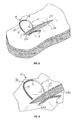
- proximal end 12 of knotless wound closure device 10 is shown having penetrated both wound edges 24, 24a and approaching at least one of the plurality of through holes 16 of knotless wound closure device 10.
- proximal end 12 is shown about to penetrate through one of the plurality of through holes 16.
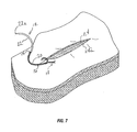
- the proximal end 12 is shown penetrating through a through-hole 16.
- surface features 14 are compressed as they pass through through-hole 16 of knotless wound closure device 10 and expand upon exiting the other side of through-hole 16 thereby preventing reversal of the suture back through the through-hole 16.
- the cross sectional dimension of flexible body 20 and the diameter of through-hole 16 may be formed so as to create an interference or friction fit between the two thereby securing device 10 through a friction fit as shown in FIG. 7 .
- the knotless wound closure device may be constructed from materials selected from the group consisting of surgical fibers, sutures, filaments, tapes, slit sheets, and ribbons.
- a suture in accordance with the present disclosure may be of monofilament or multifilament construction.
- the suture may have both a proximal and distal end, with barbs projecting from the elongated body towards at least one end thereby forming an included angle of less than about 90 degrees between the barbs and the suture body.
- a bioactive agent may be deposited within the barb angles, that is, the angle formed between the barb and suture surface. Placement of a bioactive agent in the angle formed between the barbs and suture surface places the bioactive agent at precisely defined locations within a tissue wound closure, which thereby provides a unique controlled and sustained release dosage form.
- the wound closure device in accordance with the present disclosure may be formed of degradable materials, non-degradable materials, and combinations thereof.
- Suitable degradable materials which may be utilized to form the device include natural collagenous materials or synthetic resins including those derived from alkylene carbonates such as trimethylene carbonate, tetramethylene carbonate, and the like, caprolactone, dioxanone, glycolic acid, lactic acid, glycolide, lactide, homopolymers thereof, copolymers thereof, and combinations thereof.
- glycolide and lactide based polyesters, especially copolymers of glycolide and lactide may be utilized to form a suture of the present disclosure.
- Suitable non-degradable materials which may be utilized to form the device of the present disclosure include polyolefins, such as polyethylene, polypropylene, copolymers of polyethylene and polypropylene, and blends of polyethylene and polypropylene; polyamides (also known as nylon); polyesters such as polyethylene terephthalate; polytetrafluoroethylene; polyether-esters such as polybutester; polytetramethylene ether glycol; 1,4-butanediol; polyurethanes; and combinations thereof.
- non-degradable materials may include silk, cotton, linen, carbon fibers, and the like.
- polypropylene can be utilized to form the suture.
- the polypropylene can be isotactic polypropylene or a mixture of isotactic and syndiotactic or atactic polypropylene.
- Filaments used for forming wound closure devices of the present disclosure may be formed using any technique within the purview of those skilled in the art, such as, for example, extrusion, molding and/or solvent casting.
- the strands can be extruded through an extruder unit of a conventional type, such as those disclosed in U.S. Pat. Nos. 6,063,105 ; 6,203,564 ; and 6,235,869 , the entire contents of each of which are incorporated by reference herein.
- the device of the present disclosure may include a yarn made of more than one filament, which may contain multiple filaments of the same or different materials.
- the suture can be made using any known technique such as, for example, braiding, weaving or knitting, each of which may be formed by any suitable method within the purview of those skilled in the art.
- the filaments may also be combined to produce a non-woven suture.
- the filaments themselves may be drawn, oriented, crinkled, twisted, commingled or air entangled to form yarns as part of the suture forming process.
- the device Once the device is constructed, it can be sterilized by any means within the purview of those skilled in the art.
- Wound closure devices in accordance with the present disclosure may be coated or impregnated with one or more medico-surgically useful substances, e.g., bioactive agents which accelerate or beneficially modify the healing process when the device is applied to a wound or surgical site.
- bioactive agents include, for example, biocidal agents, antibiotics, antimicrobial agents, medicants, growth factors, anti-clotting agents, analgesics, anesthetics, anti-inflammatory agents, wound repair agents and the like, and combinations thereof.
- Bioactive agents may be applied onto the wound closure device of the present disclosure utilizing any method within the purview of one skilled in the art including, for example, dipping, spraying, vapor deposition, brushing, compounding and the like.
- Surface features may be formed on the elongated flexible body of the wound closure device utilizing any method within the purview of one skilled in the art. Such methods include, but are not limited to, cutting, molding, and the like.
- surface features may be formed by making with acute angular cuts directly into the elongated flexible body, with cut portions pushed outwardly and separated from the body. The depth of the surface features thus formed generally away from the elongated flexible body may depend on the diameter of the material and the depth of the cut.
- a suitable device for cutting a plurality of axially spaced surface features on the exterior of a filament may use a cutting bed, a cutting bed vise, a cutting template, and a blade assembly to perform the cutting.
- the cutting device has the ability to produce a plurality of axially spaced surface features such as barbs in the same or random configuration and at different angles in relation to each other.
- Other suitable methods of cutting the barbs include the use of a laser or manual methods.
- the device can be packaged in any number of desired pre-cut lengths and in pre-shaped curves.
- all of the surface features may be aligned to allow the elongated body of the knotless wound closure device to move through tissue in one direction and resist moving through tissue in the opposite direction.
- the surface features 14 on elongated body 20 may be formed into a single directional wound closure device 10.
- elongated body 20 may be attached to needle 22.
- the surface features 14 permit movement of device 10 through tissue in the direction of movement of a needle end 22 but are generally rigid in an opposite direction and prevent movement of device 10 in a direction opposite the direction of movement of a needle end 22.
- the surface features may be aligned on a first portion of a length of a body to allow movement of a first end of the device through tissue in one direction, while surface features on a second portion of the length of the body may be aligned to allow movement of the second end of the device in an opposite direction.
- the surface features may be arranged in any suitable pattern, for example, in a helical pattern.
- the number, configuration, spacing and surface area of the surface features can vary depending upon the tissue in which the wound closure device is used, as well as the composition and geometry of the material utilized to form the wound closure device. Additionally, the proportions of the surface features may remain relatively constant while the overall length of the surface features and the spacing of the surface features may be determined by the tissue being connected. For example, if the wound closure device is to be used to connect the edges of a wound in skin or tendon, the surface features may be made relatively short and more rigid to facilitate entry into this rather firm tissue. Alternatively, if the wound closure device is intended for use in fatty tissue, which is relatively soft, the surface features may be made longer and spaced further apart to increase the ability of the wound closure device to grip the soft tissue.
- the surface area of the surface features can also vary.
- fuller-tipped surface features can be made of varying sizes designed for specific surgical applications. For joining fat and relatively soft tissues, larger surface features may be desired, whereas smaller surface features may be more suitable for collagen-dense tissues.
- a combination of large and small surface features within the same structure may be beneficial, for example when a wound closure device is used in tissue repair with differing layer structures. Use of the combination of large and small surface features with the same wound closure device wherein barb sizes are customized for each tissue layer will ensure maximum anchoring properties.
- a single directional wound closure device as depicted in FIG. 1 may have both large and small surface features; in other embodiments a bi-directional wound closure device (not shown) may have both large and small surface features.
- the wound closure device of the present disclosure may be utilized for all wound closure techniques and tissue connection procedures.
- Procedures can include endoscopic techniques, plastic and reconstructive surgeries, general wound closure, cardiovascular tissues, orthopedics, obstetrics, gynecology and urology.
- Typical tissue types include the various layers of muscle, ligaments, tendons, fascia, fat and/or skin.
- a knotless wound closure device includes an elongated flexible body with proximal and distal ends having a plurality of through-holes along its length and defining a longitudinal axis with a plurality of surface features extending away from the axis.
- the proximal end is configured and dimensioned to pass through body tissue and thereafter be selectively passed through at least one of the plurality of through-holes such that at least one of the surface features also passes through the through-hole thereby forming a locked closed loop to secure body tissue held therein.
Abstract
Description
- The present disclosure generally relates to wound closure devices having an uninterrupted or continuous stitch.
- For many years, surgeons have sealed tissue wounds using various wound closure devices and methods. Suturing is a surgical technique involving the connection of tissue by stitching the tissue together with a strand of appropriate suturing material.
- Typically, a suture is prepared by piercing a needle with the suture attached through tissue on both sides of a wound, by pulling the ends of the suture to bring the sides of the wound together, and tying the suture into a knot. The knot preserves the tension on the suture to maintain the sides of the wound in approximation and allow the tissue to heal. An improperly tied knot can slip and untie at a tension far lower than the tension required to break the suture. When the suture is internal to the body, replacement of the failed suture can require another surgery.
- A variety of devices have been developed for the transcutaneous placement, tying, and tightening of suture knots through a tissue tract. Despite the skill and due care involved in placing, tying, and tightening a suture knot using these devices, seepage of blood and fluids at the suture site and into the tissue tract can still occur.
- Thus, there remains a need for fast and straightforward systems and methods to achieve wound closure, which are substantially free of blood or fluid leakage about the wound closure site. There also remains a need for a wound closure device utilized as a continuous stitch which can have multi-use per patient instead of multiple sutures used for one wound closure. Furthermore, there still remains a need for a self anchoring wound closure device having a secure locking mechanism.
- The present disclosure includes a knotless wound closure device which includes an elongated flexible body having a proximal end, a distal end and defining a longitudinal axis with a plurality of surface features extending generally away from the longitudinal axis. A plurality of through-holes are disposed along the length of the elongated flexible body wherein the proximal end is configured and dimensioned to pass through body tissue and thereafter be selectively passed through at least one of the plurality of through-holes such that at least one of the surface features also passes through at least one through-hole and thereby forming a locked closed loop to secure body tissue held therein.
- The present disclosure also includes a method of closing a wound which includes using such wound closure devices by passing the proximal end of the device through body tissue at least once and subsequently passing the proximal end through at least one of the plurality of through-holes and forming a locked closed loop to secure body tissue held therein.
- Various embodiments of the present disclosure will be described hereinbelow with reference to the figures wherein:
-
FIG. 1 is a perspective view of a knotless wound closure device attached to a needle in accordance with the present disclosure; -
FIGS. 2A-D are top plan views of alternative embodiments of the plurality of through holes ofFIG. 1 in accordance with the present disclosure; -
FIGS. 3A-I are cross sectional views of alternative embodiments of the elongated flexible body and surface features of the embodiment ofFIG. 1 in accordance with the present disclosure; and -
FIGS. 4-7 illustrate a series of steps employing the method of closing a wound in accordance with the present disclosure. - Described herein are knotless wound closure devices utilized to form a continuous stitch and having an opposing anchoring point to function properly. The knotless wound closure device of the present disclosure eliminates the failure rate caused at or near the anchor point which would have caused support of the tissue approximation to be lost and seepage of blood and fluids to occur. The unique geometry and use of the knotless wound closure device also reduces or eliminates patient discomfort caused by the sharp protrusions which may be felt with a barbed suture device.
- Accordingly, the knotless wound closure device is created with a specific geometry, namely with a plurality of surface features which interface with uniquely matching through-holes created through the length of the longitudinal axis of the elongated flexible body of the wound closure device which function as a unidirectional locking mechanism.
- Referring now in detail to the drawings in which like reference numerals are applied to like elements in the various views, knotless
wound closure device 10 is shown inFIG. 1 and generally includes an elongatedflexible body 20 having aproximal end 12 with aneedle 22 attachedflexible body 20 and adistal end 18 and defining a longitudinal axis A-A. A plurality of surface features 14 extend generally away from the longitudinal axis A-A. Additionally, plurality of through-holes 16 are formed along the length of the elongatedflexible body 20 wherein theneedle 22 includes a sharpenedtip 22a which is configured and dimensioned to pass through body tissue and thereafter be selectively passed through at least one of the plurality of through-holes 16 such that at least one of thesurface features 14 also passes through the at least one through-hole 16 thereby forming a locked closed loop to secure body tissue held therein. - Referring to
FIGS. 2A-D , in various alternative embodiments, the cross-sectional geometry of the plurality of through-holes 16 may consist of a key-shape (FIG. 2A ), a compound wedge (FIG. 2B ), a wedge (FIG. 2C ) and a circle (FIG. 2D ). - Referring now to
FIGS. 3A-I , in various alternative embodiments, the cross-sectional geometry of the elongatedflexible body 20 may consist of an oval shape (FIG. 3A ), a flat tape shape (FIG. 3B ), an elliptical shape (FIG. 3C ), a round shape (FIG. 3D ), an octagon shape (FIG. 3E ), an oblique shape (FIG. 3F ), a rectangle shape (FIG. 3G ), a star shape (FIG. 3H ) and a square (FIG. 3I ). - In alternative embodiments, the
surface features 14 may consist of barbs, hooks, latches, protrusions, leaves, teeth and/or combinations thereof. - Referring to
FIGS. 4-7 , a series of steps or processes for an illustrative method of closing a wound using the knotless wound closure device described above is shown. In use,surface features 14 are interlaced through plurality of through-holes 16 penetrating through the longitudinal axis of elongatedflexible body 20 and securing through a friction fit. Thus, as tension is applied to the device, a wedging action occurs thereby resulting in a more secure locking mechanism. The knotlesswound closure device 10 and method of closing the wound is intended for general wound closure and can be utilized as either an "uninterrupted" or "continuous" stitch. The device will also support multi single unit use per patient. - In
FIG.4 ,proximal end 12 of knotlesswound closure device 10 is shown having penetrated bothwound edges holes 16 of knotlesswound closure device 10. - In
FIG. 5 ,proximal end 12 is shown about to penetrate through one of the plurality of throughholes 16. - In
FIG. 6 , theproximal end 12 is shown penetrating through a through-hole 16. Asproximal end 12 penetrates fully through the through-hole 16 (not shown) and the suture is pulled through through-hole 16,surface features 14 are compressed as they pass through through-hole 16 of knotlesswound closure device 10 and expand upon exiting the other side of through-hole 16 thereby preventing reversal of the suture back through the through-hole 16. Additionally, the cross sectional dimension offlexible body 20 and the diameter of through-hole 16 may be formed so as to create an interference or friction fit between the two thereby securingdevice 10 through a friction fit as shown inFIG. 7 . - In various embodiments, the knotless wound closure device may be constructed from materials selected from the group consisting of surgical fibers, sutures, filaments, tapes, slit sheets, and ribbons.
- In embodiments, a suture in accordance with the present disclosure may be of monofilament or multifilament construction. The suture may have both a proximal and distal end, with barbs projecting from the elongated body towards at least one end thereby forming an included angle of less than about 90 degrees between the barbs and the suture body. Additionally, a bioactive agent may be deposited within the barb angles, that is, the angle formed between the barb and suture surface. Placement of a bioactive agent in the angle formed between the barbs and suture surface places the bioactive agent at precisely defined locations within a tissue wound closure, which thereby provides a unique controlled and sustained release dosage form.
- The wound closure device in accordance with the present disclosure may be formed of degradable materials, non-degradable materials, and combinations thereof. Suitable degradable materials which may be utilized to form the device include natural collagenous materials or synthetic resins including those derived from alkylene carbonates such as trimethylene carbonate, tetramethylene carbonate, and the like, caprolactone, dioxanone, glycolic acid, lactic acid, glycolide, lactide, homopolymers thereof, copolymers thereof, and combinations thereof. In some embodiments, glycolide and lactide based polyesters, especially copolymers of glycolide and lactide, may be utilized to form a suture of the present disclosure.
- Suitable non-degradable materials which may be utilized to form the device of the present disclosure include polyolefins, such as polyethylene, polypropylene, copolymers of polyethylene and polypropylene, and blends of polyethylene and polypropylene; polyamides (also known as nylon); polyesters such as polyethylene terephthalate; polytetrafluoroethylene; polyether-esters such as polybutester; polytetramethylene ether glycol; 1,4-butanediol; polyurethanes; and combinations thereof. In other embodiments, non-degradable materials may include silk, cotton, linen, carbon fibers, and the like. In some useful embodiments, polypropylene can be utilized to form the suture. The polypropylene can be isotactic polypropylene or a mixture of isotactic and syndiotactic or atactic polypropylene.
- Filaments used for forming wound closure devices of the present disclosure may be formed using any technique within the purview of those skilled in the art, such as, for example, extrusion, molding and/or solvent casting. In embodiments, the strands can be extruded through an extruder unit of a conventional type, such as those disclosed in
U.S. Pat. Nos. 6,063,105 ;6,203,564 ; and6,235,869 , the entire contents of each of which are incorporated by reference herein. - The device of the present disclosure may include a yarn made of more than one filament, which may contain multiple filaments of the same or different materials. Where the device is made of multiple filaments, the suture can be made using any known technique such as, for example, braiding, weaving or knitting, each of which may be formed by any suitable method within the purview of those skilled in the art. The filaments may also be combined to produce a non-woven suture. The filaments themselves may be drawn, oriented, crinkled, twisted, commingled or air entangled to form yarns as part of the suture forming process.
- Once the device is constructed, it can be sterilized by any means within the purview of those skilled in the art.
- Wound closure devices in accordance with the present disclosure may be coated or impregnated with one or more medico-surgically useful substances, e.g., bioactive agents which accelerate or beneficially modify the healing process when the device is applied to a wound or surgical site. Suitable bioactive agents include, for example, biocidal agents, antibiotics, antimicrobial agents, medicants, growth factors, anti-clotting agents, analgesics, anesthetics, anti-inflammatory agents, wound repair agents and the like, and combinations thereof. Bioactive agents may be applied onto the wound closure device of the present disclosure utilizing any method within the purview of one skilled in the art including, for example, dipping, spraying, vapor deposition, brushing, compounding and the like.
- Surface features may be formed on the elongated flexible body of the wound closure device utilizing any method within the purview of one skilled in the art. Such methods include, but are not limited to, cutting, molding, and the like. In some embodiments, surface features may be formed by making with acute angular cuts directly into the elongated flexible body, with cut portions pushed outwardly and separated from the body. The depth of the surface features thus formed generally away from the elongated flexible body may depend on the diameter of the material and the depth of the cut. In some embodiments, a suitable device for cutting a plurality of axially spaced surface features on the exterior of a filament may use a cutting bed, a cutting bed vise, a cutting template, and a blade assembly to perform the cutting. In operation, the cutting device has the ability to produce a plurality of axially spaced surface features such as barbs in the same or random configuration and at different angles in relation to each other. Other suitable methods of cutting the barbs include the use of a laser or manual methods. The device can be packaged in any number of desired pre-cut lengths and in pre-shaped curves.
- In various embodiments, all of the surface features may be aligned to allow the elongated body of the knotless wound closure device to move through tissue in one direction and resist moving through tissue in the opposite direction. For example, referring to
FIG. 1 , the surface features 14 onelongated body 20 may be formed into a single directionalwound closure device 10. In embodiments elongatedbody 20 may be attached toneedle 22. The surface features 14 permit movement ofdevice 10 through tissue in the direction of movement of aneedle end 22 but are generally rigid in an opposite direction and prevent movement ofdevice 10 in a direction opposite the direction of movement of aneedle end 22. - In other embodiments, the surface features may be aligned on a first portion of a length of a body to allow movement of a first end of the device through tissue in one direction, while surface features on a second portion of the length of the body may be aligned to allow movement of the second end of the device in an opposite direction.
- The surface features may be arranged in any suitable pattern, for example, in a helical pattern. The number, configuration, spacing and surface area of the surface features can vary depending upon the tissue in which the wound closure device is used, as well as the composition and geometry of the material utilized to form the wound closure device. Additionally, the proportions of the surface features may remain relatively constant while the overall length of the surface features and the spacing of the surface features may be determined by the tissue being connected. For example, if the wound closure device is to be used to connect the edges of a wound in skin or tendon, the surface features may be made relatively short and more rigid to facilitate entry into this rather firm tissue. Alternatively, if the wound closure device is intended for use in fatty tissue, which is relatively soft, the surface features may be made longer and spaced further apart to increase the ability of the wound closure device to grip the soft tissue.
- The surface area of the surface features can also vary. For example, fuller-tipped surface features can be made of varying sizes designed for specific surgical applications. For joining fat and relatively soft tissues, larger surface features may be desired, whereas smaller surface features may be more suitable for collagen-dense tissues. In some embodiments, a combination of large and small surface features within the same structure may be beneficial, for example when a wound closure device is used in tissue repair with differing layer structures. Use of the combination of large and small surface features with the same wound closure device wherein barb sizes are customized for each tissue layer will ensure maximum anchoring properties. In certain embodiments, a single directional wound closure device as depicted in
FIG. 1 may have both large and small surface features; in other embodiments a bi-directional wound closure device (not shown) may have both large and small surface features. - The wound closure device of the present disclosure may be utilized for all wound closure techniques and tissue connection procedures. Procedures can include endoscopic techniques, plastic and reconstructive surgeries, general wound closure, cardiovascular tissues, orthopedics, obstetrics, gynecology and urology. Typical tissue types include the various layers of muscle, ligaments, tendons, fascia, fat and/or skin.
- There is also described a method of closing a wound comprising the steps of:
- providing the knotless wound closure device as described herein and passing the proximal end of the knotless wound closure device through body tissue at least once and subsequently passing the proximal end through at least one of the plurality of through-holes thereby forming a locked closed loop to secure body tissue held therein.
- A knotless wound closure device includes an elongated flexible body with proximal and distal ends having a plurality of through-holes along its length and defining a longitudinal axis with a plurality of surface features extending away from the axis. The proximal end is configured and dimensioned to pass through body tissue and thereafter be selectively passed through at least one of the plurality of through-holes such that at least one of the surface features also passes through the through-hole thereby forming a locked closed loop to secure body tissue held therein.
- While the above description contains many specifics, these specifics should not be construed as limitations on the scope of the disclosure, but merely as exemplifications of embodiments thereof. Those skilled in the art will envision many other possibilities within the scope and spirit of the disclosure as defined by the claims appended hereto.
Claims (9)
- A knotless wound closure device comprising:an elongated flexible body having a proximal end and a distal end, the elongated flexible body defining a longitudinal axis;a plurality of surface features extending generally away from the longitudinal axis;a plurality of through-holes formed along the length of the elongated flexible body;wherein the proximal end is configured and dimensioned to pass through body tissue and thereafter be selectively passed through at least one of the plurality of through-holes such that at least one of the surface features also passes through the at least one through-hole thereby forming a locked closed loop to secure body tissue held therein.
- The knotless wound closure device of claim 1, wherein the device is constructed from materials selected from the group consisting of surgical fibers, sutures, filaments, tapes, slit sheets, and ribbons.
- The knotless wound closure device of claim 1, wherein the cross-sectional geometry of the plurality of through-holes is selected from the group consisting of a key-shape, a wedge, a circle and a compound wedge.
- The knotless wound closure device of claim 1, wherein the cross-sectional geometry of the elongated flexible body is selected from the group consisting of an oval, a rectangle, all ellipse, a circle, a square, a star, an oblique and an octagon.
- The knotless wound closure device of claim 1, wherein the surface features are selected from the group consisting of barbs, hooks, latches, protrusions, leaves, teeth and/or combinations thereof.
- The knotless wound closure device of claim 1, wherein the proximal end further comprises a needle secured thereto.
- The knotless wound closure device of claim 1, wherein the surface features includes a bioactive agent within an included angle of the surface feature and the elongated flexible body.
- The knotless wound closure device of claim 7, wherein the bioactive agent is selected from the group consisting of biocidal agents, antibiotics, antimicrobial agents, medicaments, growth factors, anti-clotting agents, anesthetics, anti-inflammatory agents, wound repair agents and combinations thereof.
- A knotless wound closure device according to any of the preceding claims for use in closing a wound.
Priority Applications (1)
| Application Number | Priority Date | Filing Date | Title |
|---|---|---|---|
| EP10166547.9A EP2229893B1 (en) | 2006-12-05 | 2007-12-05 | Knotless wound closure device |
Applications Claiming Priority (1)
| Application Number | Priority Date | Filing Date | Title |
|---|---|---|---|
| US11/567,129 US20080132943A1 (en) | 2006-12-05 | 2006-12-05 | Knotless wound closure device |
Related Child Applications (1)
| Application Number | Title | Priority Date | Filing Date |
|---|---|---|---|
| EP10166547.9 Division-Into | 2010-06-18 |
Publications (3)
| Publication Number | Publication Date |
|---|---|
| EP1929961A2 true EP1929961A2 (en) | 2008-06-11 |
| EP1929961A3 EP1929961A3 (en) | 2009-03-11 |
| EP1929961B1 EP1929961B1 (en) | 2011-02-23 |
Family
ID=39267748
Family Applications (2)
| Application Number | Title | Priority Date | Filing Date |
|---|---|---|---|
| EP10166547.9A Active EP2229893B1 (en) | 2006-12-05 | 2007-12-05 | Knotless wound closure device |
| EP07254703A Active EP1929961B1 (en) | 2006-12-05 | 2007-12-05 | Knotless wound closure device |
Family Applications Before (1)
| Application Number | Title | Priority Date | Filing Date |
|---|---|---|---|
| EP10166547.9A Active EP2229893B1 (en) | 2006-12-05 | 2007-12-05 | Knotless wound closure device |
Country Status (8)
| Country | Link |
|---|---|
| US (1) | US20080132943A1 (en) |
| EP (2) | EP2229893B1 (en) |
| JP (1) | JP5553961B2 (en) |
| CN (1) | CN101219066B (en) |
| AU (1) | AU2007237207B2 (en) |
| CA (1) | CA2610608A1 (en) |
| DE (1) | DE602007012646D1 (en) |
| ES (1) | ES2359584T3 (en) |
Cited By (12)
| Publication number | Priority date | Publication date | Assignee | Title |
|---|---|---|---|---|
| WO2009155273A1 (en) | 2008-06-17 | 2009-12-23 | Ethicon, Inc. | Collapsible barbed sutures having reduced drag |
| WO2010011532A1 (en) * | 2008-07-23 | 2010-01-28 | Ethicon, Inc. | Collapsible barbed sutures having reduced drag and methods therefor |
| KR101038073B1 (en) | 2010-06-25 | 2011-06-01 | 양현진 | Tube type medical needle unit and method for inserting medical sutures therein |
| EP2623041A3 (en) * | 2012-02-01 | 2013-09-11 | Covidien LP | Wound closure device |
| EP2684527A2 (en) * | 2011-03-07 | 2014-01-15 | John Jacobs Medical Inc. | Suture thread |
| US9220492B2 (en) | 2012-02-01 | 2015-12-29 | Covidien Lp | Wound closure device |
| US9480473B2 (en) | 2011-12-27 | 2016-11-01 | Y.Jacobs Medical Inc. | Knotless suture, and kit containing same |
| WO2017078492A1 (en) * | 2015-11-05 | 2017-05-11 | (주)제이월드 | Suture and method for producing same |
| US10010317B2 (en) | 2012-12-05 | 2018-07-03 | Young Jae Kim | Method of improving elasticity of tissue of living body |
| US10178990B2 (en) | 2012-12-05 | 2019-01-15 | Y. Jacobs Medical Inc. | Apparatus for inserting surgical thread, and surgical procedure kit for inserting surgical thread comprising same |
| US10226320B2 (en) | 2013-12-06 | 2019-03-12 | Y.Jacobs Medical Inc. | Apparatus for inserting medical tube and surgical procedure kit for inserting medical tube, having same |
| EP3823539A4 (en) * | 2018-07-18 | 2022-04-27 | Arthrex, Inc. | Knotless closure sutures and methods of tissue fixation |
Families Citing this family (45)
| Publication number | Priority date | Publication date | Assignee | Title |
|---|---|---|---|---|
| US6241747B1 (en) | 1993-05-03 | 2001-06-05 | Quill Medical, Inc. | Barbed Bodily tissue connector |
| US8795332B2 (en) | 2002-09-30 | 2014-08-05 | Ethicon, Inc. | Barbed sutures |
| US5931855A (en) | 1997-05-21 | 1999-08-03 | Frank Hoffman | Surgical methods using one-way suture |
| US7056331B2 (en) | 2001-06-29 | 2006-06-06 | Quill Medical, Inc. | Suture method |
| US6848152B2 (en) | 2001-08-31 | 2005-02-01 | Quill Medical, Inc. | Method of forming barbs on a suture and apparatus for performing same |
| US6773450B2 (en) | 2002-08-09 | 2004-08-10 | Quill Medical, Inc. | Suture anchor and method |
| US8100940B2 (en) | 2002-09-30 | 2012-01-24 | Quill Medical, Inc. | Barb configurations for barbed sutures |
| US20040088003A1 (en) | 2002-09-30 | 2004-05-06 | Leung Jeffrey C. | Barbed suture in combination with surgical needle |
| US7624487B2 (en) | 2003-05-13 | 2009-12-01 | Quill Medical, Inc. | Apparatus and method for forming barbs on a suture |
| CN104224253A (en) | 2004-05-14 | 2014-12-24 | 伊西康有限责任公司 | Suture methods and devices |
| US8663277B2 (en) | 2005-06-29 | 2014-03-04 | Ethicon, Inc. | Braided barbed suture |
| US20080255612A1 (en) | 2007-04-13 | 2008-10-16 | Angiotech Pharmaceuticals, Inc. | Self-retaining systems for surgical procedures |
| US20080281357A1 (en) * | 2007-05-09 | 2008-11-13 | An-Min Jason Sung | Looped tissue-grasping device |
| ES2479290T3 (en) | 2007-09-27 | 2014-07-23 | Ethicon Llc | A system for cutting a retainer in a suture |
| BRPI0820129B8 (en) | 2007-12-19 | 2021-06-22 | Angiotech Pharm Inc | process of formation of a self-retaining suture and self-retaining suture |
| US8916077B1 (en) | 2007-12-19 | 2014-12-23 | Ethicon, Inc. | Self-retaining sutures with retainers formed from molten material |
| US8118834B1 (en) | 2007-12-20 | 2012-02-21 | Angiotech Pharmaceuticals, Inc. | Composite self-retaining sutures and method |
| US8615856B1 (en) | 2008-01-30 | 2013-12-31 | Ethicon, Inc. | Apparatus and method for forming self-retaining sutures |
| ES2602570T3 (en) | 2008-01-30 | 2017-02-21 | Ethicon Llc | Apparatus and method for forming self-retaining sutures |
| EP2249712B8 (en) | 2008-02-21 | 2018-12-26 | Ethicon LLC | Method and apparatus for elevating retainers on self-retaining sutures |
| US8216273B1 (en) | 2008-02-25 | 2012-07-10 | Ethicon, Inc. | Self-retainers with supporting structures on a suture |
| US8641732B1 (en) | 2008-02-26 | 2014-02-04 | Ethicon, Inc. | Self-retaining suture with variable dimension filament and method |
| JP5619726B2 (en) | 2008-04-15 | 2014-11-05 | エシコン・エルエルシーEthicon, LLC | Self-retaining suture with bidirectional retainer or unidirectional retainer |
| US8961560B2 (en) | 2008-05-16 | 2015-02-24 | Ethicon, Inc. | Bidirectional self-retaining sutures with laser-marked and/or non-laser marked indicia and methods |
| US8932328B2 (en) | 2008-11-03 | 2015-01-13 | Ethicon, Inc. | Length of self-retaining suture and method and device for using the same |
| JP2010119402A (en) * | 2008-11-17 | 2010-06-03 | Masafumi Noda | Hemostasis device for internal organ |
| WO2011140283A2 (en) | 2010-05-04 | 2011-11-10 | Angiotech Pharmaceuticals, Inc. | Self-retaining systems having laser-cut retainers |
| EP2579787B1 (en) | 2010-06-11 | 2016-11-30 | Ethicon, LLC | Suture delivery tools for endoscopic and robot-assisted surgery |
| CN103747746B (en) * | 2010-11-03 | 2017-05-10 | 伊西康有限责任公司 | Drug-eluting self-retaining sutures and methods relating thereto |
| MX342984B (en) | 2010-11-09 | 2016-10-19 | Ethicon Llc | Emergency self-retaining sutures and packaging. |
| WO2012129534A2 (en) | 2011-03-23 | 2012-09-27 | Angiotech Pharmaceuticals, Inc. | Self-retaining variable loop sutures |
| US20130172931A1 (en) | 2011-06-06 | 2013-07-04 | Jeffrey M. Gross | Methods and devices for soft palate tissue elevation procedures |
| US9788838B2 (en) | 2011-10-11 | 2017-10-17 | Zone 2 Surgical, Inc. | Tissue device |
| BR112014020564B1 (en) * | 2012-02-23 | 2021-05-11 | Northwestern University | medical device and soft tissue repositioning method |
| US9872679B2 (en) * | 2013-02-05 | 2018-01-23 | Ethicon, Inc. | Locally reversible barbed sutures |
| US9539004B2 (en) * | 2013-03-08 | 2017-01-10 | Zone 2 Surgical, Inc. | Collapsible locking suture |
| US9301746B2 (en) | 2013-10-11 | 2016-04-05 | Abbott Cardiovascular Systems, Inc. | Suture-based closure with hemostatic tract plug |
| KR101432499B1 (en) * | 2013-11-18 | 2014-08-25 | 유원석 | Suture thread insertion kit |
| US9451953B2 (en) | 2013-12-11 | 2016-09-27 | Depuy Mitek, Llc | Knotless collapsible sutures and methods for suturing |
| RU2679577C2 (en) * | 2014-01-27 | 2019-02-11 | Этикон, Инк. | Device for suturing with retention suture with asymmetric retainers and method for manufacture thereof |
| WO2018117305A1 (en) * | 2016-12-23 | 2018-06-28 | (주)제이월드 | Device for manufacturing medical suture and method for manufacturing suture |
| US11026676B2 (en) | 2017-02-06 | 2021-06-08 | Covidien Lp | Surgical wound closure apparatus |
| KR200491562Y1 (en) * | 2018-11-06 | 2020-04-27 | 주식회사 엠에이치메디 | Suture for Lifting |
| CN109480932A (en) * | 2018-11-09 | 2019-03-19 | 付亚坤 | A kind of epidermis beauty treatment suturing device |
| EP3934547A4 (en) * | 2020-05-15 | 2022-08-10 | Moliver, MD, Facs, Clayton L. | Knotless sutures including integrated closures |
Citations (3)
| Publication number | Priority date | Publication date | Assignee | Title |
|---|---|---|---|---|
| US6063105A (en) | 1996-06-18 | 2000-05-16 | United States Surgical | Medical devices fabricated from elastomeric alpha-olefins |
| US6203564B1 (en) | 1998-02-26 | 2001-03-20 | United States Surgical | Braided polyester suture and implantable medical device |
| US6235869B1 (en) | 1998-10-20 | 2001-05-22 | United States Surgical Corporation | Absorbable polymers and surgical articles fabricated therefrom |
Family Cites Families (24)
| Publication number | Priority date | Publication date | Assignee | Title |
|---|---|---|---|---|
| US3123077A (en) * | 1964-03-03 | Surgical suture | ||
| US3072986A (en) * | 1958-02-27 | 1963-01-15 | Lefnaer Otto | Bag lock and packing means |
| US3224054A (en) * | 1963-02-13 | 1965-12-21 | Frederick O Lige | Wire ties |
| US3570497A (en) * | 1969-01-16 | 1971-03-16 | Gerald M Lemole | Suture apparatus and methods |
| US4466159A (en) * | 1981-07-06 | 1984-08-21 | Burrage Robert H | Adjustable tie strap |
| US5053047A (en) * | 1989-05-16 | 1991-10-01 | Inbae Yoon | Suture devices particularly useful in endoscopic surgery and methods of suturing |
| US5123913A (en) * | 1989-11-27 | 1992-06-23 | Wilk Peter J | Suture device |
| US5236563A (en) * | 1990-06-18 | 1993-08-17 | Advanced Surface Technology Inc. | Surface-modified bioabsorbables |
| US5403346A (en) * | 1992-12-31 | 1995-04-04 | Loeser; Edward A. | Self-affixing suture assembly |
| US8795332B2 (en) * | 2002-09-30 | 2014-08-05 | Ethicon, Inc. | Barbed sutures |
| US6241747B1 (en) * | 1993-05-03 | 2001-06-05 | Quill Medical, Inc. | Barbed Bodily tissue connector |
| US5500000A (en) * | 1993-07-01 | 1996-03-19 | United States Surgical Corporation | Soft tissue repair system and method |
| US5643295A (en) * | 1994-12-29 | 1997-07-01 | Yoon; Inbae | Methods and apparatus for suturing tissue |
| DE19628909C2 (en) * | 1996-07-18 | 1999-11-18 | Ruesch Willy Ag | Closure |
| US5683417A (en) * | 1996-08-14 | 1997-11-04 | Cooper; William I. | Suture and method for endoscopic surgery |
| US5987706A (en) * | 1997-11-06 | 1999-11-23 | Micron Electronics, Inc. | Device for removably coupling a plurality of structures |
| JP2001198131A (en) * | 2000-01-18 | 2001-07-24 | Matsuda Ika Kk | Suture for operation having ring |
| US7172615B2 (en) * | 2000-05-19 | 2007-02-06 | Coapt Systems, Inc. | Remotely anchored tissue fixation device |
| US7556647B2 (en) * | 2003-10-08 | 2009-07-07 | Arbor Surgical Technologies, Inc. | Attachment device and methods of using the same |
| CA2546611A1 (en) * | 2003-12-04 | 2005-06-23 | Ethicon, Inc. | Active suture for the delivery of therapeutic fluids |
| CN2719234Y (en) * | 2004-07-26 | 2005-08-24 | 朱亚平 | Surgical operation suture line |
| CA2526541C (en) * | 2004-12-01 | 2013-09-03 | Tyco Healthcare Group Lp | Novel biomaterial drug delivery and surface modification compositions |
| US20070224237A1 (en) * | 2006-03-24 | 2007-09-27 | Julia Hwang | Barbed sutures having a therapeutic agent thereon |
| US8100941B2 (en) * | 2008-06-17 | 2012-01-24 | Ethicon, Inc. | Collapsible barbed sutures having reduced drag and methods therefor |
-
2006
- 2006-12-05 US US11/567,129 patent/US20080132943A1/en not_active Abandoned
-
2007
- 2007-11-14 CA CA002610608A patent/CA2610608A1/en not_active Abandoned
- 2007-11-22 AU AU2007237207A patent/AU2007237207B2/en active Active
- 2007-11-22 JP JP2007303770A patent/JP5553961B2/en active Active
- 2007-12-05 ES ES07254703T patent/ES2359584T3/en active Active
- 2007-12-05 EP EP10166547.9A patent/EP2229893B1/en active Active
- 2007-12-05 EP EP07254703A patent/EP1929961B1/en active Active
- 2007-12-05 DE DE602007012646T patent/DE602007012646D1/en active Active
- 2007-12-05 CN CN2007101949466A patent/CN101219066B/en active Active
Patent Citations (3)
| Publication number | Priority date | Publication date | Assignee | Title |
|---|---|---|---|---|
| US6063105A (en) | 1996-06-18 | 2000-05-16 | United States Surgical | Medical devices fabricated from elastomeric alpha-olefins |
| US6203564B1 (en) | 1998-02-26 | 2001-03-20 | United States Surgical | Braided polyester suture and implantable medical device |
| US6235869B1 (en) | 1998-10-20 | 2001-05-22 | United States Surgical Corporation | Absorbable polymers and surgical articles fabricated therefrom |
Cited By (24)
| Publication number | Priority date | Publication date | Assignee | Title |
|---|---|---|---|---|
| US8100941B2 (en) | 2008-06-17 | 2012-01-24 | Ethicon, Inc. | Collapsible barbed sutures having reduced drag and methods therefor |
| WO2009155273A1 (en) | 2008-06-17 | 2009-12-23 | Ethicon, Inc. | Collapsible barbed sutures having reduced drag |
| US8821539B2 (en) | 2008-07-23 | 2014-09-02 | Ethicon, Inc. | Collapsible barbed sutures having reduced drag and methods therefor |
| WO2010011532A1 (en) * | 2008-07-23 | 2010-01-28 | Ethicon, Inc. | Collapsible barbed sutures having reduced drag and methods therefor |
| KR101038073B1 (en) | 2010-06-25 | 2011-06-01 | 양현진 | Tube type medical needle unit and method for inserting medical sutures therein |
| WO2011162511A3 (en) * | 2010-06-25 | 2012-04-12 | Heeyoung Lee | Tube-type medical needle unit and method of inserting plurality of medical sutures into tube-type medical needle |
| EP2684527A4 (en) * | 2011-03-07 | 2014-12-03 | John Jacobs Medical Inc | Suture thread |
| EP2684527A2 (en) * | 2011-03-07 | 2014-01-15 | John Jacobs Medical Inc. | Suture thread |
| US11103230B2 (en) | 2011-03-07 | 2021-08-31 | Y.Jacobs Medical Inc. | Suture thread |
| US9808234B2 (en) | 2011-03-07 | 2017-11-07 | Y. Jacobs Medical Inc. | Suture thread |
| US9848865B2 (en) | 2011-03-07 | 2017-12-26 | Y.Jacobs Medical Inc. | Suture thread |
| US9480473B2 (en) | 2011-12-27 | 2016-11-01 | Y.Jacobs Medical Inc. | Knotless suture, and kit containing same |
| US11103232B2 (en) | 2011-12-27 | 2021-08-31 | Y.Jacobs Medical Inc. | Knotless suture, and kit containing same |
| US9924937B2 (en) | 2011-12-27 | 2018-03-27 | Y.Jacobs Medical Inc. | Knotless suture, and kit containing same |
| US9107660B2 (en) | 2012-02-01 | 2015-08-18 | Covidien Lp | Wound closure device |
| US9220492B2 (en) | 2012-02-01 | 2015-12-29 | Covidien Lp | Wound closure device |
| EP2623041A3 (en) * | 2012-02-01 | 2013-09-11 | Covidien LP | Wound closure device |
| US10010317B2 (en) | 2012-12-05 | 2018-07-03 | Young Jae Kim | Method of improving elasticity of tissue of living body |
| US10178990B2 (en) | 2012-12-05 | 2019-01-15 | Y. Jacobs Medical Inc. | Apparatus for inserting surgical thread, and surgical procedure kit for inserting surgical thread comprising same |
| US10226320B2 (en) | 2013-12-06 | 2019-03-12 | Y.Jacobs Medical Inc. | Apparatus for inserting medical tube and surgical procedure kit for inserting medical tube, having same |
| US11241303B2 (en) | 2013-12-06 | 2022-02-08 | Y.Jacobs Medical Inc. | Apparatus for inserting medical tube and surgical procedure kit for inserting medical tube, having same |
| US10918378B2 (en) | 2015-11-05 | 2021-02-16 | Jworld Co., Ltd. | Suture and method for producing same |
| WO2017078492A1 (en) * | 2015-11-05 | 2017-05-11 | (주)제이월드 | Suture and method for producing same |
| EP3823539A4 (en) * | 2018-07-18 | 2022-04-27 | Arthrex, Inc. | Knotless closure sutures and methods of tissue fixation |
Also Published As
| Publication number | Publication date |
|---|---|
| CN101219066B (en) | 2012-02-08 |
| EP1929961B1 (en) | 2011-02-23 |
| EP2229893B1 (en) | 2013-07-10 |
| CN101219066A (en) | 2008-07-16 |
| EP1929961A3 (en) | 2009-03-11 |
| AU2007237207A1 (en) | 2008-06-19 |
| AU2007237207B2 (en) | 2014-01-16 |
| CA2610608A1 (en) | 2008-06-05 |
| ES2359584T3 (en) | 2011-05-24 |
| JP5553961B2 (en) | 2014-07-23 |
| US20080132943A1 (en) | 2008-06-05 |
| DE602007012646D1 (en) | 2011-04-07 |
| JP2008142536A (en) | 2008-06-26 |
| EP2229893A1 (en) | 2010-09-22 |
Similar Documents
| Publication | Publication Date | Title |
|---|---|---|
| EP2229893B1 (en) | Knotless wound closure device | |
| RU2372100C2 (en) | Configuration of agnails for suture filaments with agnails | |
| JP4493501B2 (en) | Back-tipped suture | |
| JP5570046B2 (en) | Mooring device | |
| US8333788B2 (en) | Knotted suture end effector | |
| US7967841B2 (en) | Methods for using looped tissue-grasping devices | |
| US20080281357A1 (en) | Looped tissue-grasping device | |
| US20100298872A1 (en) | Surgical suture material consisting of braided thread | |
| US20110282386A1 (en) | Continuous-filament thread having a plurality of barbs and a barbed suture | |
| EP2289427A1 (en) | System and method for creating end effector | |
| EP2623040B1 (en) | Wound closure device | |
| KR102332026B1 (en) | Self-retaining suture device with asymmetric retainers and method of making same | |
| US9107660B2 (en) | Wound closure device |
Legal Events
| Date | Code | Title | Description |
|---|---|---|---|
| PUAI | Public reference made under article 153(3) epc to a published international application that has entered the european phase |
Free format text: ORIGINAL CODE: 0009012 |
|
| AK | Designated contracting states |
Kind code of ref document: A2 Designated state(s): AT BE BG CH CY CZ DE DK EE ES FI FR GB GR HU IE IS IT LI LT LU LV MC MT NL PL PT RO SE SI SK TR |
|
| AX | Request for extension of the european patent |
Extension state: AL BA HR MK RS |
|
| PUAL | Search report despatched |
Free format text: ORIGINAL CODE: 0009013 |
|
| AK | Designated contracting states |
Kind code of ref document: A3 Designated state(s): AT BE BG CH CY CZ DE DK EE ES FI FR GB GR HU IE IS IT LI LT LU LV MC MT NL PL PT RO SE SI SK TR |
|
| AX | Request for extension of the european patent |
Extension state: AL BA HR MK RS |
|
| 17P | Request for examination filed |
Effective date: 20090821 |
|
| AKX | Designation fees paid |
Designated state(s): DE ES FR GB IE IT |
|
| 17Q | First examination report despatched |
Effective date: 20091027 |
|
| GRAP | Despatch of communication of intention to grant a patent |
Free format text: ORIGINAL CODE: EPIDOSNIGR1 |
|
| GRAS | Grant fee paid |
Free format text: ORIGINAL CODE: EPIDOSNIGR3 |
|
| GRAA | (expected) grant |
Free format text: ORIGINAL CODE: 0009210 |
|
| AK | Designated contracting states |
Kind code of ref document: B1 Designated state(s): DE ES FR GB IE IT |
|
| REG | Reference to a national code |
Ref country code: GB Ref legal event code: FG4D |
|
| REG | Reference to a national code |
Ref country code: IE Ref legal event code: FG4D |
|
| REF | Corresponds to: |
Ref document number: 602007012646 Country of ref document: DE Date of ref document: 20110407 Kind code of ref document: P |
|
| REG | Reference to a national code |
Ref country code: DE Ref legal event code: R096 Ref document number: 602007012646 Country of ref document: DE Effective date: 20110407 |
|
| REG | Reference to a national code |
Ref country code: ES Ref legal event code: FG2A Ref document number: 2359584 Country of ref document: ES Kind code of ref document: T3 Effective date: 20110524 |
|
| PLBE | No opposition filed within time limit |
Free format text: ORIGINAL CODE: 0009261 |
|
| STAA | Information on the status of an ep patent application or granted ep patent |
Free format text: STATUS: NO OPPOSITION FILED WITHIN TIME LIMIT |
|
| PGFP | Annual fee paid to national office [announced via postgrant information from national office to epo] |
Ref country code: ES Payment date: 20111226 Year of fee payment: 5 |
|
| 26N | No opposition filed |
Effective date: 20111124 |
|
| REG | Reference to a national code |
Ref country code: DE Ref legal event code: R097 Ref document number: 602007012646 Country of ref document: DE Effective date: 20111124 |
|
| PG25 | Lapsed in a contracting state [announced via postgrant information from national office to epo] |
Ref country code: IT Free format text: LAPSE BECAUSE OF NON-PAYMENT OF DUE FEES Effective date: 20121205 |
|
| REG | Reference to a national code |
Ref country code: ES Ref legal event code: FD2A Effective date: 20140527 |
|
| PG25 | Lapsed in a contracting state [announced via postgrant information from national office to epo] |
Ref country code: ES Free format text: LAPSE BECAUSE OF NON-PAYMENT OF DUE FEES Effective date: 20121206 |
|
| REG | Reference to a national code |
Ref country code: FR Ref legal event code: PLFP Year of fee payment: 9 |
|
| REG | Reference to a national code |
Ref country code: FR Ref legal event code: PLFP Year of fee payment: 10 |
|
| REG | Reference to a national code |
Ref country code: FR Ref legal event code: PLFP Year of fee payment: 11 |
|
| PGFP | Annual fee paid to national office [announced via postgrant information from national office to epo] |
Ref country code: GB Payment date: 20231124 Year of fee payment: 17 |
|
| PGFP | Annual fee paid to national office [announced via postgrant information from national office to epo] |
Ref country code: IE Payment date: 20231123 Year of fee payment: 17 Ref country code: FR Payment date: 20231122 Year of fee payment: 17 Ref country code: DE Payment date: 20231121 Year of fee payment: 17 |