EP1923823A2 - Radio frequency identification (RFID) system for manufacturing, distribution and retailing of keys - Google Patents
Radio frequency identification (RFID) system for manufacturing, distribution and retailing of keys Download PDFInfo
- Publication number
- EP1923823A2 EP1923823A2 EP20080151635 EP08151635A EP1923823A2 EP 1923823 A2 EP1923823 A2 EP 1923823A2 EP 20080151635 EP20080151635 EP 20080151635 EP 08151635 A EP08151635 A EP 08151635A EP 1923823 A2 EP1923823 A2 EP 1923823A2
- Authority
- EP
- European Patent Office
- Prior art keywords
- key
- rfid
- information
- keys
- rfid tag
- Prior art date
- Legal status (The legal status is an assumption and is not a legal conclusion. Google has not performed a legal analysis and makes no representation as to the accuracy of the status listed.)
- Granted
Links
Images


Classifications
-
- G—PHYSICS
- G06—COMPUTING; CALCULATING OR COUNTING
- G06K—GRAPHICAL DATA READING; PRESENTATION OF DATA; RECORD CARRIERS; HANDLING RECORD CARRIERS
- G06K19/00—Record carriers for use with machines and with at least a part designed to carry digital markings
- G06K19/06—Record carriers for use with machines and with at least a part designed to carry digital markings characterised by the kind of the digital marking, e.g. shape, nature, code
- G06K19/067—Record carriers with conductive marks, printed circuits or semiconductor circuit elements, e.g. credit or identity cards also with resonating or responding marks without active components
- G06K19/07—Record carriers with conductive marks, printed circuits or semiconductor circuit elements, e.g. credit or identity cards also with resonating or responding marks without active components with integrated circuit chips
- G06K19/077—Constructional details, e.g. mounting of circuits in the carrier
- G06K19/07749—Constructional details, e.g. mounting of circuits in the carrier the record carrier being capable of non-contact communication, e.g. constructional details of the antenna of a non-contact smart card
-
- A—HUMAN NECESSITIES
- A45—HAND OR TRAVELLING ARTICLES
- A45C—PURSES; LUGGAGE; HAND CARRIED BAGS
- A45C11/00—Receptacles for purposes not provided for in groups A45C1/00-A45C9/00
- A45C11/32—Bags or wallets for holding keys
- A45C11/321—Bags or wallets for holding keys combined with other articles
-
- E—FIXED CONSTRUCTIONS
- E05—LOCKS; KEYS; WINDOW OR DOOR FITTINGS; SAFES
- E05B—LOCKS; ACCESSORIES THEREFOR; HANDCUFFS
- E05B19/00—Keys; Accessories therefor
-
- E—FIXED CONSTRUCTIONS
- E05—LOCKS; KEYS; WINDOW OR DOOR FITTINGS; SAFES
- E05B—LOCKS; ACCESSORIES THEREFOR; HANDCUFFS
- E05B19/00—Keys; Accessories therefor
- E05B19/24—Key distinguishing marks
-
- G—PHYSICS
- G06—COMPUTING; CALCULATING OR COUNTING
- G06K—GRAPHICAL DATA READING; PRESENTATION OF DATA; RECORD CARRIERS; HANDLING RECORD CARRIERS
- G06K19/00—Record carriers for use with machines and with at least a part designed to carry digital markings
- G06K19/04—Record carriers for use with machines and with at least a part designed to carry digital markings characterised by the shape
- G06K19/041—Constructional details
- G06K19/048—Constructional details the record carrier being shaped as a key
-
- G—PHYSICS
- G06—COMPUTING; CALCULATING OR COUNTING
- G06K—GRAPHICAL DATA READING; PRESENTATION OF DATA; RECORD CARRIERS; HANDLING RECORD CARRIERS
- G06K19/00—Record carriers for use with machines and with at least a part designed to carry digital markings
- G06K19/06—Record carriers for use with machines and with at least a part designed to carry digital markings characterised by the kind of the digital marking, e.g. shape, nature, code
- G06K19/067—Record carriers with conductive marks, printed circuits or semiconductor circuit elements, e.g. credit or identity cards also with resonating or responding marks without active components
- G06K19/07—Record carriers with conductive marks, printed circuits or semiconductor circuit elements, e.g. credit or identity cards also with resonating or responding marks without active components with integrated circuit chips
- G06K19/077—Constructional details, e.g. mounting of circuits in the carrier
- G06K19/07749—Constructional details, e.g. mounting of circuits in the carrier the record carrier being capable of non-contact communication, e.g. constructional details of the antenna of a non-contact smart card
- G06K19/07758—Constructional details, e.g. mounting of circuits in the carrier the record carrier being capable of non-contact communication, e.g. constructional details of the antenna of a non-contact smart card arrangements for adhering the record carrier to further objects or living beings, functioning as an identification tag
- G06K19/0776—Constructional details, e.g. mounting of circuits in the carrier the record carrier being capable of non-contact communication, e.g. constructional details of the antenna of a non-contact smart card arrangements for adhering the record carrier to further objects or living beings, functioning as an identification tag the adhering arrangement being a layer of adhesive, so that the record carrier can function as a sticker
-
- G—PHYSICS
- G07—CHECKING-DEVICES
- G07C—TIME OR ATTENDANCE REGISTERS; REGISTERING OR INDICATING THE WORKING OF MACHINES; GENERATING RANDOM NUMBERS; VOTING OR LOTTERY APPARATUS; ARRANGEMENTS, SYSTEMS OR APPARATUS FOR CHECKING NOT PROVIDED FOR ELSEWHERE
- G07C9/00—Individual registration on entry or exit
- G07C9/00174—Electronically operated locks; Circuits therefor; Nonmechanical keys therefor, e.g. passive or active electrical keys or other data carriers without mechanical keys
- G07C9/00944—Details of construction or manufacture
-
- E—FIXED CONSTRUCTIONS
- E05—LOCKS; KEYS; WINDOW OR DOOR FITTINGS; SAFES
- E05B—LOCKS; ACCESSORIES THEREFOR; HANDCUFFS
- E05B17/00—Accessories in connection with locks
- E05B17/0004—Lock assembling or manufacturing
-
- G—PHYSICS
- G07—CHECKING-DEVICES
- G07C—TIME OR ATTENDANCE REGISTERS; REGISTERING OR INDICATING THE WORKING OF MACHINES; GENERATING RANDOM NUMBERS; VOTING OR LOTTERY APPARATUS; ARRANGEMENTS, SYSTEMS OR APPARATUS FOR CHECKING NOT PROVIDED FOR ELSEWHERE
- G07C9/00—Individual registration on entry or exit
- G07C9/00174—Electronically operated locks; Circuits therefor; Nonmechanical keys therefor, e.g. passive or active electrical keys or other data carriers without mechanical keys
- G07C2009/00753—Electronically operated locks; Circuits therefor; Nonmechanical keys therefor, e.g. passive or active electrical keys or other data carriers without mechanical keys operated by active electrical keys
- G07C2009/00769—Electronically operated locks; Circuits therefor; Nonmechanical keys therefor, e.g. passive or active electrical keys or other data carriers without mechanical keys operated by active electrical keys with data transmission performed by wireless means
- G07C2009/00793—Electronically operated locks; Circuits therefor; Nonmechanical keys therefor, e.g. passive or active electrical keys or other data carriers without mechanical keys operated by active electrical keys with data transmission performed by wireless means by Hertzian waves
-
- G—PHYSICS
- G07—CHECKING-DEVICES
- G07C—TIME OR ATTENDANCE REGISTERS; REGISTERING OR INDICATING THE WORKING OF MACHINES; GENERATING RANDOM NUMBERS; VOTING OR LOTTERY APPARATUS; ARRANGEMENTS, SYSTEMS OR APPARATUS FOR CHECKING NOT PROVIDED FOR ELSEWHERE
- G07C2209/00—Indexing scheme relating to groups G07C9/00 - G07C9/38
- G07C2209/60—Indexing scheme relating to groups G07C9/00174 - G07C9/00944
- G07C2209/62—Comprising means for indicating the status of the lock
-
- G—PHYSICS
- G07—CHECKING-DEVICES
- G07C—TIME OR ATTENDANCE REGISTERS; REGISTERING OR INDICATING THE WORKING OF MACHINES; GENERATING RANDOM NUMBERS; VOTING OR LOTTERY APPARATUS; ARRANGEMENTS, SYSTEMS OR APPARATUS FOR CHECKING NOT PROVIDED FOR ELSEWHERE
- G07C9/00—Individual registration on entry or exit
- G07C9/00174—Electronically operated locks; Circuits therefor; Nonmechanical keys therefor, e.g. passive or active electrical keys or other data carriers without mechanical keys
- G07C9/00896—Electronically operated locks; Circuits therefor; Nonmechanical keys therefor, e.g. passive or active electrical keys or other data carriers without mechanical keys specially adapted for particular uses
-
- Y—GENERAL TAGGING OF NEW TECHNOLOGICAL DEVELOPMENTS; GENERAL TAGGING OF CROSS-SECTIONAL TECHNOLOGIES SPANNING OVER SEVERAL SECTIONS OF THE IPC; TECHNICAL SUBJECTS COVERED BY FORMER USPC CROSS-REFERENCE ART COLLECTIONS [XRACs] AND DIGESTS
- Y10—TECHNICAL SUBJECTS COVERED BY FORMER USPC
- Y10T—TECHNICAL SUBJECTS COVERED BY FORMER US CLASSIFICATION
- Y10T70/00—Locks
- Y10T70/70—Operating mechanism
- Y10T70/7051—Using a powered device [e.g., motor]
- Y10T70/7062—Electrical type [e.g., solenoid]
- Y10T70/7068—Actuated after correct combination recognized [e.g., numerical, alphabetical, or magnet[s] pattern]
- Y10T70/7073—Including use of a key
- Y10T70/7079—Key rotated [e.g., Eurocylinder]
-
- Y—GENERAL TAGGING OF NEW TECHNOLOGICAL DEVELOPMENTS; GENERAL TAGGING OF CROSS-SECTIONAL TECHNOLOGIES SPANNING OVER SEVERAL SECTIONS OF THE IPC; TECHNICAL SUBJECTS COVERED BY FORMER USPC CROSS-REFERENCE ART COLLECTIONS [XRACs] AND DIGESTS
- Y10—TECHNICAL SUBJECTS COVERED BY FORMER USPC
- Y10T—TECHNICAL SUBJECTS COVERED BY FORMER US CLASSIFICATION
- Y10T70/00—Locks
- Y10T70/70—Operating mechanism
- Y10T70/7441—Key
- Y10T70/778—Operating elements
- Y10T70/7791—Keys
- Y10T70/7876—Bow or head
-
- Y—GENERAL TAGGING OF NEW TECHNOLOGICAL DEVELOPMENTS; GENERAL TAGGING OF CROSS-SECTIONAL TECHNOLOGIES SPANNING OVER SEVERAL SECTIONS OF THE IPC; TECHNICAL SUBJECTS COVERED BY FORMER USPC CROSS-REFERENCE ART COLLECTIONS [XRACs] AND DIGESTS
- Y10—TECHNICAL SUBJECTS COVERED BY FORMER USPC
- Y10T—TECHNICAL SUBJECTS COVERED BY FORMER US CLASSIFICATION
- Y10T70/00—Locks
- Y10T70/80—Parts, attachments, accessories and adjuncts
- Y10T70/8432—For key-operated mechanism
- Y10T70/8676—Key holders
Definitions
- This invention relates generally to the application of Radio Frequency Identification (“RFID”) technology to the key industry or similar industries with relatively fungible, yet nuanced products. Specifically, the invention relates to systems that include the use of RFID tags to identify a key or a group of keys for purposes of gaining efficiency and accuracy in the supply chain.
- RFID Radio Frequency Identification
- This difficulty of identification causes additional difficulties when counting, inventorying, distributing and retailing such fungible objects. These difficulties may occur throughout the entire supply chain for these objects or products - from manufacturing through distribution and into retailing.
- the key industry is one such industry in which the relatively fungible nature of the products leads to difficulties in identification, counting, inventorying, distributing, and retailing.
- the key industry supply chain includes many "nodes" at which key or key blanks change hands.
- keys are handled by manufacturers, truckers, customs agents, shippers, wholesalers, and retailers, many of which may be located overseas and often handle hundreds, if not thousands, of types of keys or key blanks. Many of these keys or key blanks are not readily distinguishable from other similar keys or key blanks, which adds complexity and cost to the supply chain.
- At each node in the supply chain many administrative tasks must be completed, such as inventorying and counting the keys in a shipment.
- transmittal and bill of lading documents must be reviewed and created.
- these processes are accomplished via expensive, inaccurate manual counts and human visual reviews. The current processes may result in higher than required safety stocks, stock outs, lost sales, miscut keys and other unnecessary expenses.
- Utility patent application 10/633,933 entitled OBJECT IDENTIFICATION SYSTEM, which is incorporated herein in full and attached hereto as Appendix A, presents solutions for some common issues that arise in the duplication of certain fungible keys at retail locations in the supply chain. However, there still remains a need to develop additional solutions for duplication issues and for the many other issues presented by the movement of products with a fungible nature, such as keys, through the supply chain.
- the present invention generally provides apparatus and methods for tracking, counting and inventorying keys throughout the supply chain, from manufacturing through retailing to the end user.
- the present invention provides apparatus and methods for improving the accuracy of duplicating keys.
- the apparatus and methods generally rely on Radio Frequency Identification (RFID) technology, where information is stored to and collected from RFID tags that are located proximate to keys.
- RFID Radio Frequency Identification
- Figure 1 is a chart illustrating a supply chain for the key industry
- Figure 2 an exploded view of a RFID tag attached to a key by a one-sided adhesive label
- Figure 3 is a perspective view of a RFID tag attached to a key body
- Figure 4 is a perspective view of a RFID tag attached to a head of a key
- Figure 5 is a perspective view of a RFID tag incorporated into the head of a key
- Figure 6 is a perspective view of a RFID tag attached to a sheath for a key
- Figure 7 is a perspective view of a RFID tag incorporated into a cylinder, which is attached to a key;
- Figure 8 is a perspective view of a RFID-enabled merchandising rack
- Figure 9 is a process chart illustrating a method for restocking a RFID-enabled merchandising rack
- Figure 10 is a process chart illustrating a method for choosing a proper key blank to make a duplicate key
- Figure 11 is a process chart illustrating a method for determining the inventory of keys in a RFID-enabled merchandising rack
- Figure 12 is a process chart illustrating a method for using an RFID-enabled key cutter
- Figure 13 is a process chart illustrating a method for using an RFID-enabled key cutter.
- RFID Radio Frequency Identification
- RFID systems are capable of identifying, counting, and tracking RFID tagged keys through the use of solid state silicon chips and radio waves.
- RFID has numerous advantages versus existing methods and technologies currently used in the key industry. Current methods include manual counting, mechanical counting, and universal product code (UPC) systems.
- UPC universal product code
- Custom Software can be part of an RFID system to evaluate, utilize, and manipulate information gathered to reduce costs and increase accuracy and efficiency throughout the key supply chain. For example, software can automate the creation of transmittal and bill of lading, can reduce inventory expenses by reducing safety stocks throughout the supply chain, and can increase sales by eliminating stock outs throughout the key supply chain.
- Automatic identification by RFID also facilitates other transactions, for example, proper key blank selection for cutting a duplicate key and identifying inventory losses or shrinkage.
- An RFID system can be comprised of a variety of components and can be configured in a variety of ways. Depending on the purpose served by an RFID system, the system may comprise combinations of the following hardware: RFID tags attached to individual products, shipping containers, and pallets; RFID readers, attached or incorporated into merchandising display racks, loading and unloading equipment, shipping vehicles, and warehousing locations; RFID multiplexers, attached or incorporated into merchandising racks, loading and unloading equipment, shipping vehicles, and warehousing locations; handheld or portable RFID readers; computer hardware, such as computers, servers, monitors, and printers; telecommunications hardware, such as modems and routers; and key cutting machines. Also incorporated into RFID systems can be software components, including: RFID reader software or middleware; database software; telecommunications software; network and internet integration software; and user interface or graphic interface software.
- RFID systems included in this application can be comprised of any combination of hardware and software components detailed in this application.
- combinations of hardware and software components that are similar or equivalent to those described in this application are also included in this application.
- FIG. 1 shows nodes of a typical supply chain 10 used for the key industry.
- the illustration of Figure 1 is exemplary only and a supply chain 10 can comprise any combination of the nodes shown and could, in addition, include nodes that are not illustrated in Figure 1 .
- a key or key blank originates at a key manufacturer 12.
- Keys leaves the manufacturing facility, normally via a trucker 14, and may have to pass through a customs inspection 16 if the key is passing through an international or state boarder.
- the keys may then be shipped 18 and re-inspected by customs 16 upon reaching a destination country.
- the keys may then be moved by a trucker 14 to a supplier, distributor, or wholesaler 20 .
- the keys will then be sent a retailer 22 , who will sell the keys or key blanks to the end user 24 .
- RFID tags can be incorporated or attached to keys, key blanks, prefabricated keys, original keys, and the like.
- key and “key blank” will include keys, key blanks, prefabricated keys, original keys, groups of keys, and the like.
- Tags can be attached to or incorporated into keys in a variety of ways.
- FIG. 2 is an exploded view showing a key 32, an RFID tag 30, and a one-sided adhesive UPC label 34.
- a RFID tag 30 can be attached to the adhesive side of the UPC label 34, which is then attached to the key 32.
- the use of a UPC one-sided label 34 is for convenience, as UPC labels are commonly used in the key industry to identify keys. As the key market adjusts to the introduction of RFID technology, there will be a period of overlap where the current UPC systems will coexist with novel RFID systems. This embodiment accounts for that overlap.
- An alternative embodiment is to use a blank one-sided adhesive label to secure a tag to a key. This embodiment may be more practical when keys pass through a supply chain 10 that has fully adopted RFID technology.
- FIG 3 illustrates another embodiment of a tag 30 attached to a key 32.
- the RFID tag 30 is affixed directly to the key 32 itself.
- a tag 30 can be affixed either permanently or in a manner that allows the tag 30 to be removed at any point in the supply chain 10.
- the affixing of the RFID tag 30 can be limited to the head 36 of the key 32, as illustrated in Figure 4 .
- This area of the key can be designed to provide ample room for the placement of an RFID tag 30.
- the head 36 of the key 32 is not affected by the cutting of teeth into a key 32 and would be more likely left undisturbed by the process of cutting a replacement key.
- only the silicon chip portion of an RFID tag is affixed directly to a metal key.
- the key itself serves as the antenna by which the information is relayed to an RFID reader.
- the placement of the chip could be anywhere on the key that allows for contact with a metal portion of the key.
- Figure 5 illustrates an alternative embodiment of the invention where an RFID tag 30 is incorporated directly into the key 32.
- One optional method of achieving this is to make all, or a portion, of the key 32 out of a plastic material. It is common for keys to be manufactured with a plastic head 38 and a metal body 40 , which extends from the plastic head 38. In addition, with advancements in thermal set plastics and other polymer technologies, it is practical to manufacture an entire key 32 out of a plastic material.
- An RFID tag 30 can be incorporated into a key 32 by embedding the tag 30 in a plastic portion of the key during the molding process used to manufacture the plastic portion of the key.
- Figure 5 illustrates an embodiment where an RFID tag 30 is incorporated into the plastic head 38 of a key 32.
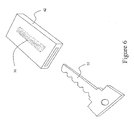
- FIG. 6 illustrates an alternative embodiment of the invention, where the RFID tag 30 is permanently incorporated into a plastic sheath or sleeve 42 by injection molding or other means.
- the key 32 can be conveniently inserted or removed from the sheath or sleeve 42.
- the RFID tag 30 residing in the sheath or sleeve 42 can be reprogrammed and reused upon removal of the key 32.
- a RFID tag 30 can be attached or adhered to a surface of the sheath or sleeve 42.
- Figure 7 illustrates another alternative embodiment, where the RFID tag 30 is permanently incorporated into a member 44.
- the member 44 may be any shape, for instance a disc, cube, or cylinder and may be manufactured out of plastic by injection molding or other means.
- the member 44, with the incorporated RFID tag 30, can be attached to the key 32 by means of chain, strap or other ligament 46 through a hole 48 in the head 38 of the key 32. Because RFID tags 30 can be relatively expensive, the tag 30 attached to the key 32 can be reused or recycled after the key 32 is ultimately sold to the consumer. In an alternative embodiment, an RFID tag 30 can be attached to adhered to a surface of the member.
- an RFID system may utilize RFID tags that are attached or affixed to a container or multiple containers holding numerous keys. Such a container could hold a "manufactured lot" or "keys in bulk.”
- the information stored on the RFID tag can contain information that is general to the keys in the container, such as number and type of keys or who manufactured the keys.
- RFID readers transmit and receive RF signals and can gather information stored on RFID tags 30.
- a RFID reader can also receive and respond to commands from a host computer and transfer data gathered from RFID tags 30 to the host computer.
- RFID readers There are various types of RFID readers. Fixed RFID readers can be permanently affixed to stationery objects such as walls, or mounted on stands or portals. Tunnel readers can be mounted on conveyors. Mobile readers can be mounted on forklifts or pickers. Hand held readers provide portability and close range. The selection of a reader depends on the demands of a specific key supply chain node.
- RFID software can be utilized for many different purposes in RFID systems.
- Reader software or middleware can be responsible for RFID reader configuration and administration, data filtering and event management via business rules written specifically for each node in a supply chain 10 .
- Network and web integration software can be responsible for routing gathered data to the correct application and correct node in the supply chain 10 , for guaranteeing delivery and for interfacing with applications.
- Application software can be responsible for creating a database for tracking and counting key inventory by location.
- User interface software can generate a graphical dash board that supports an RFID system user in making timely business decisions based on the information displayed, such as type of keys, by revealing the stock keeping unit ("SKU"), and location and number of specific keys regarding the disposition of inventories across the key supply chain 10 . Decisions made based on displayed information include increasing or decreasing the rate of production for specific keys, decreasing or increasing safety stock levels at any node, restocking a retail location, holding a sale to decrease overstock inventory and diverting inventory from one location to another.
- the system could be configured to notify the system user of the need to take action or to actually perform the action required according to a set of predetermined business rules.
- the system may automatically restock keys or key blanks at a given location but not at another by electronically ordering only the necessary items at the necessary locations.
- the user interface software may provide this information on a local store basis, regional basis, or by national store brand. Additional insights can be gained from near real time inventory tracking, include identification of stores and shifts at which significant trends or cycles are taking place or in which shrinkage occurs. These insights can be used to take appropriate action to maximize sales and minimize losses. Furthermore, trends and projections from historical data can be plotted on graphs and evaluated through "what if" scenarios to determine the optimal response. All of these rules, decisions, and methods can be based on data gathered by the RFID reader or combinations of RFID readers that are used to track and gather information from the key RFID tags 30.
- FIG 8 illustrates an element that can be incorporated into an RFID system to increase efficiency and accuracy in the retail portion 22 of the supply chain 10, an RFID-enabled merchandising rack 50.
- This rack 50 is disclosed in U.S. Patent Application No. 10/633,933 , as part of a key identification system ("KID system"), which is attached hereto as Appendix A.
- KID system key identification system
- This rack 50 can be utilized in retail facilities to store keys and key blanks 32 .
- the rack 50 can facilitate organizing and displaying the keys 32 .
- Figure 8 illustrates keys 32 displayed on spindles or pegs 52 . In an alternative embodiment, keys 32 can be displayed in bins. Bins can be used for key blanks kept in bulk quantities due to their status as "fast movers.”
- the rack 50 can utilize one or more RFID readers and a number of multiplexed antennas.
- these antennas may serve as the spindle or peg 52 upon which the keys 32 are stored and displayed.
- Each antenna similar to typical readers, creates a separate read zone of radio frequency energy which reads information from any RFID tagged key 32 in or entering into the read zone.
- Multi-colored light emitting diodes (LED's) 54 may be located above the spindles 52 (as shown in Figure 8 ) or at the end of the spindles 52 to serve as visual indicators to be energized based on circumstance.
- the rack may utilize one or more RFID readers, one or more antennas that may be multiplexed and a device for measuring the weight of keys 32 stored in each bin.
- the number of keys in each bin is estimated by dividing the total weight of the keys 32 in a bin by the weight of a single key 32 of the type in the bin.
- radio frequencies that can be utilized by RFID systems used in a supply chain 10. These frequencies include, but are not limited to, low frequency (approximately 125-135 KHz), high frequency (approximately 13.56 MHz) and ultra high frequency (approximately 860-930 MHz).
- the preferred mode for the RFID systems and for the RFID-enabled merchandising rack 50 is 13.56 MHz. It provides the best compromise between RFID tag 30 cost and ability to provide distinct and appropriate read zones for the RFID-enabled merchandising rack 50 .
- the RFID-enabled merchandising rack 50 may communicate with other components of the system.
- the rack 50 can communicate with an RFID reader, which then communicates with a host computer. This may allow inventory and other data to be used by the system to make decisions through application logic or allow a user of the system to make decisions based on display information shown through a user interface.
- RFID radio frequency identification
- LAN local area network
- WLAN wireless local area network
- a communication interface between a host computer and a system user can be a vital element in an RFID system.
- the communication of information or data to a system user can be converted to actionable information on which business decisions are made.
- the actionable information can includes graphic and numerical representations of inventory at each store location, each region of the country, or each distribution facility.
- the user interface can represent this information in graphic, tabular and numeric form by time period. Typically, only a sale should cause a decrease in store level inventory; therefore, it is valuable to compare the decrease in inventory to point of sale (“POS”) data to analyze if a shrinkage problem exists in the supply chain 10 .
- the user interface can also represents information in graphic, tabular and numeric form by time period for each truck shipment, each trucking region, each shipment on a ship, each shipment on a shipping line and each manufacturer.
- An RFID system that utilizes an RFID-enabled merchandizing rack 50 can be used in many ways to gain efficiency and accuracy in a supply chain.
- One example is to use an RFID system when restocking a RFID-enabled merchandising rack 50 in a retail environment.
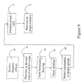
- Figure 9 shows a method of restocking a merchandising rack 50.
- a stock clerk picks up individual keys for evaluation and placement on individual spindles 52 .
- the accuracy of the restocking relies on the retail clerk's eyes, mind and hands. This extremely repetitive set of actions provides many opportunities for error.
- the retail clerk places a key 32 with an RFID tag 30 in the read zone of an RFID reader 62.
- the RFID reader reads information 64 from the attached tag 32 and queries 66 a database located on a host computer.
- the host computer returns information identifying the proper spindle 54 or bin on which the key 32 should be placed 68.
- the host computer sends a command to the rack 50 to energize 70 the LED 54 that corresponds with the correct spindle 52 or bin.
- the clerk then placed 72 the key 32 on the proper spindle or in the proper bin.
- the process may continue so that when the key bearing the RFID tag enters the appropriate read zone the LED 54 is again energized or an audible noise is produced indicating that the key blank 32 has been put on the correct spindle 52 or in the proper bin. If the key 32 enters the wrong read zone, an LED or audible noise is produced indicating that the key has been put on the wrong spindle or in the wrong bin.
- the date and time the key 32 was stored or displayed can be recorded by the RFID system and the store inventory and accounts payable accounts automatically updated.
- the identity of the stocking clerk can also be captured if he or she is wearing or possesses a RFID identity tag which passes through a read zone.
- the RFID system allows each retail location the freedom to determine on which spindle to stock each type of key.
- the system does not require every store to stock a particular key or SKU number at the same predetermined location as all others stores. This is valuable because different stores and different geographies have preferences for different makes and types of keys and an RFID system with an RFID-enabled merchandising rack facilitates this choice. As a result, the rack allows for improved utilization of the rack space by each individual store location.
- Figure 10 illustrates a method for selecting key blanks for correctly producing duplicate keys.
- the original key is placed in the read zone of an RFID reader 80 in an attempt to read information from its RFID tag. If information can be read 82 from the original key an accurate identification can be made automatically.
- the reader can relay the information to a host computer 84 , winch can direct the merchandising rack 50 to energize the proper LED 86 indicating the spindle on which the key blank that matches the original is located.
- the user can utilize a KID system 90 to identify the proper key blank.
- the host computer can send a signal to the merchandising rack 50 to energize the LED 86 that corresponds to the proper spindle.
- the reader can read the RFID tag of the key blank that has been selected to confirm that the proper key has been selected 94. If the correct key has been selected and removed from the rack 50, an LED on the merchandising rack 50 can be energized or an audible sound can be produced to indicate success. If the wrong key has been removed, another LED on the merchandising rack 50 can be energized or a different audible sound can be produced to indicate that the wrong key blank has been selected. Alternatively, when the user has selected and removed the key blank 32 from the indicated spindle 92, the reader can be triggered to initiate an inventory. The inventory of the spindle with the removed key will be decremented by one.
- an LED can be energized or audible sound produced to notify the user. Conversely, if the wrong key blank has been selected, an LED can be energized or audible sound produced to notify the user of improper selection.
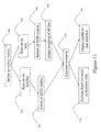
- Figure 11 illustrates a method for real time or near real time inventory recording and shrinkage tracking and prevention.
- an inventory requirement may be performed in order to determine actual inventory levels.
- Actual inventory levels can be compared to expected inventory levels to determine if inventory has been lost or stolen.
- actual inventory levels can be compared to business rules to determine if more inventory should be ordered or if existing orders should be cancelled. Determination of actual inventory begins with the initiation of an inventory inquiry 100.
- An inventory inquiry can be initiated by a system user or can be initiated by the host computer or RFID reader processing an automated rule. If keys are stored 102 on spindles 52 on a merchandizing rack 50, RFID readers on the rack 50 can be initiated 104 to inventory the rack 50. RFID readers will read all tags 30 that are within read zones and calculate an inventory 110. Alternatively if the keys are stored and displayed in bulk 106, all the bins can be weighed 108 and number of keys calculated 110 .
- Inventory inquiries may be automated to occur periodically or as requested by a user through a user interface.
- the host computer may request the inventory data or the data may be filtered by the middleware used by the readers and only communicated to the host computer if the inventory has changed in some fashion. In this way, real time or near real time inventory from every merchandising rack can be communicated to a host computer to be acted upon by automated business logic 112 or for incorporation into the information display on a user interface 114.
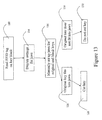
- Figures 12 and 13 illustrate methods for using an RFID system with an RFID-enabled key cutter.
- the use of such a cutter can prevent miscutting of key blanks and thus help eliminate the waste and frustration that accompanies the cutting and attempted use of miscut key blanks.
- a key blank When a key blank has been selected for cutting, it is placed into the jaws of a key cutter for holding during the cutting process. The jaws of the key cutter are set up to receive the key blank and hold it in proper position for cutting. Similarly, the original key (i.e. the one to be duplicated) is placed into a similar pair of jaws so it can be held in proper position for tracing.
- an RFID reader reads the RFID tag of the key blank 120 and communicates the key blank's identity to the key cutter 122.
- the cutter will automatically set up its jaws to accept the key blank and the original key 124 . If the original fits into the jaw configuration as set up 126, the user knows the correct key blank may have been chosen 128. If the original does not match the jaw configuration 130, the user knows that wrong key blank may have been selected 132 and that to proceed with cutting might result in a miscut.
- a manual mode is shown.
- the blank key is read by a reader 120 and jaw setting are displayed via LED or other visual means 134 to instruct the user to set up the jaws for both the key blank and original key.
- the user than manually sets up the jaws 136 . Again, if the original does not match the jaw configuration as set up 130, the user knows the wrong key blank may have been selected 132 and that to proceed with cutting may result in a miscut. If the original key fits into the jaw configuration 126 , the blank key was properly selected 128 .
- the RFID reader used for the RFID-enabled key cutter may be the same reader and antenna that are part of the RFID-enabled merchandising rack or, alternatively, the reader may be part of the merchandising rack and the antenna part of the key cutter or, alternatively, both the reader and antenna may be part of the key cutter.
- RFID systems can be utilized to achieve efficiency and accuracy throughout the supply chain 10. Once a RFID tag 30 is incorporated or attached to each key 32, the RFID tag 30 and the information it holds can be utilized to achieve improvements in accuracy and efficiency.
- a supply chain can include original manufacturers 12, carriers who move the product 14, 18, customs officials that inspect the product 16, suppliers and distributors 20 , retailers 22 , and end users 24 . Increases in accuracy and efficiency can be gained by providing easy and convenient access to information concerning keys or groups of keys 32 stored on RFID tags 30 at each nodes of a supply chain 10 and utilizing that information in making business decisions.
- the RFID tags 30 can be attached to the keys or key blanks 32 at many points in a supply chain 10 ; however, applying the tag 32 at the point of manufacturing offers the most downstream benefit.
- the key industry supply chain 10 begins in the manufacturing facility 12 , where original keys, prefabricated keys, and replacement keys 32 are produced from raw materials.
- a step in the manufacturing process is the incorporation or attachment of a RFID tag 30 to the key 32.
- RFID tag 30 is fabricated at the manufacturing facility 12
- several types of useful information can be written to the RFID tag 30 for use later in the supply chain 10. Such information includes, for example, key type, lot number, name of manufacturer, and manufacturing date. This information can also be helpful to the manufacturer by being used to prepare keys and key lots 32 for packaging and shipping.
- the keys 32 are typically packed in boxes and loaded onto pallets for shipping.
- the individual RFID tags 30 can be read to insure that the proper quantity and type of keys are loaded into each box or onto each pallet.
- RFID tags 30 can also be affixed to each box and to each pallet. Useful information can be written to these tags 30 , such as, box quantity, pallet quantity, originating address, destination address, shipment date, and employee identification. This information can later be used by the manufacturer to assemble products for final shipment and insure that orders are accurately fulfilled. A reading of the assembled products by a reader can be communicated to a host computer and can be used to produce a bill of lading for use with the shipment.
- the carrier can utilize a reader to establish that the quantity and type of keys that are being transferred are correct and accurate. The capabilities of RFID technology make this check quick and easy. Once the proper quantity and product is confirmed, the carrier can write further useful information to the RFID tag 30, such as receiving date, shipment date, and identity of the worker accepting the shipment.
- the goods may have to be inspected by national or state authorities 16.
- Inspectors can confirm the quantity and type of goods by reading the RFID tags 30 on the keys, boxes, and pallets, which can be compared to the bill of lading. This action reduces the time needed to perform standard inspections. Once the inspection is complete, the inspector can write information to the RFID tags 30, such as inspection date, inspection location, and inspector's identity.
- the shipping process 14, 18 may occur several times in the supply chain 10 .
- Keys 32 such as any retail commodity, can be handled by many middlemen before reaching the final retailer 22. These middlemen include, for example, suppliers, distributors, wholesalers, and consolidators 20 . These types of organizations can confirm the details of an arriving shipment by reading the information on the RFID tags 30 on the keys, boxes, and pallets and comparing it to the information on the bill of lading. This check can insure that no products were lost or stolen during shipment. Once the RFID tag 30 readings confirm the accuracy of the shipment, the information on the tags 30 can be used to appropriately stock or repackage the keys, update inventory records, and reconcile accounts receivable.
- tags Further useful information can then be written to the tags, such as receiving date, storage location, and workers identify. If the supplier choices to divide the shipment or consolidate it with other goods, the information on the tags 30 can be written or rewritten to correctly identify the quantity, location, and other critical information.
- a supplier, distributor, or other similar organization 20 When a supplier, distributor, or other similar organization 20 is prepared to ship an order of keys 32 to a retailer or a middleman, it can utilize the same methods manufactures use when shipping products.
- the supplier or distributor can write shipment information to tags 32 located on each key, each box, and each pallet. This information includes origination address, destination address, retailer specific serial numbers, and shipment dates.
- the shipment carrier can utilize the RFID tags 30 in the same manner as described above for carriers that deal directly with the manufacturer.
- the RFID tags 30 can be used in a variety of ways to increase efficiency and accuracy.
- the retailer 22 can read the RFID tags 30 to insure that the proper products and quantities are present and can add information to the tags 30 by writing a receiving date, along with the identity of the employee processing the shipment.
- the RFID tags 30 can be read to determine the proper stocking location for each key or lot 32 and that location information can be written to the tag 30.
- General readings of the inventory can provide many benefits. Continuous readings can provide real time inventory, which can be proactively forwarded to suppliers and other business partners. Periodic readings can be made of the inventory to insure that no improper removal or theft has occurred since the last reading. In addition, specific readings can be conducted to find the location of a specific key or key lot.
- the RFID tags 30 can be utilized to quickly locate a specific key 32 and to insure that the proper key 32 is being sold or proper replacement key is being cut. This reduces errors in sales and waste due to miscuts. In the case of replacement keys, it is important to be able to quickly identify the location of the proper key blank 32, which matches the original key to be copied.
- a reader can read the RFID tags on the retail floor and retrieve the location of the specific blank that matches the original key provided by a customer. This eliminates the need for employees to manually search the inventory and can even eliminate the need for the employee to determine which blank is appropriate.
- a general inventory reading of products on the retail floor can be taken and compared to sales records and warn of theft problems or improper shelving of keys.
- the key cutter itself may be designed to receive instructions based on information on an RFID tag 32 and to set itself up to receive the selected key blank in order to eliminate miscuts resulting from improper key cutter set up.
- the maintenance of real time or near real time inventory information constitutes another application of RFID technology that is valuable throughout the key industry supply chain 10. It is desirable for all partners in the supply chain - manufacturers 12, carriers 14,18, distributors 20, suppliers 20, and retailers 22 - to be able to quickly obtain and share inventory information with one another. It is highly beneficial for one partner to know the quantity of product currently in the possession of another partner. For example, a manufacturer can adjust its output by knowing the amount of keys that are currently inventoried at the distributor, or a supplier can prepare shipments or initiate additional orders bases on the number of keys the retailer has in inventory. One method of obtaining this information is for the manufacturer or supplier to proactively count the inventory downstream. This can be accomplished by initiating readers located at the downstream locations.
- These readers can be configured to accept remote commands via the internet or a dedicated network connection. This enables a manufacturer to send a command, through the internet or dedicated network connection, to a reader that is located in the supplier's warehouse. The reader can then read all the RFID tags 30 in the warehouse and relay, though the internet or dedicated network connection, the number of a particular key type located in the warehouse. This allows the manufacturer to obtain instant information without having to rely upon responses from the supplier.
- This same method can be used by the supplier to determine when a retailer needs a new shipment of keys. The same method can be used to determine the upstream supply. It is useful for a retailer to determine if the supplier has sufficient inventory to fulfill the retailer's needs. If the retailer finds a lack of goods to fulfill its needs, it can either inform the supplier that more product is needed or search other suppliers' inventories to fulfill the need.
- the end user 24 of a key 32 may also derives benefit from the application of RFID tags 30 on keys 32.
- the RFID tag 30 can be used to greatly reduce the chances that a miscut will not occur, which frees the end user 24 of the frustration and waste of time caused by miscuts.
- the RFID tag 24 can be configured to contain additional memory for use as mobile data storage by the end user 24 .
- An end user 24 may use the key 32 to hold retrievable data, such as automobile warranty information or dealer maintenance records on a automobile key that would convenience the user and save time.
- Security information can also be written onto the tag 30 on a key 32, such as the end user's 24 name or a personal identification number ("PIN"). This information can be used to insure that unauthorized copies of the key 32 are not made.
- a service location or retailer of blank keys 32 that duplicates keys may review the security information, such as the owner's name, and cross check that against picture ID provided by the end user 24, to insure that the owner of the key is the one requesting a duplicate key. For an added layer of security or to preserve the owners anonymity, a duplicate would only be made if a proper PIN number was provided by the customer, which matched the pin number stored on the RFID tag 30 on the key 32 .
- the present invention has numerous additional uses than solely for the key industry and key supply chain 10.
- the present invention is equally applicable to other applications wherein the tracking of inventory of a multitude of like but not identical products through manufacturing, distribution and retailing in a merchandising rack that both stores and displays provides utility via improved business efficiencies.
Abstract
Description
- This non-provisional application claims the benefit of
U.S. Provisional Patent Application No. 60/609,188 , entitled "Radio Frequency Identification (RFID) System for Manufacturing, Distributing and Retailing of Keys," filed September 10, 2004, the specification of which is hereby incorporated in its entirety. - This invention relates generally to the application of Radio Frequency Identification ("RFID") technology to the key industry or similar industries with relatively fungible, yet nuanced products. Specifically, the invention relates to systems that include the use of RFID tags to identify a key or a group of keys for purposes of gaining efficiency and accuracy in the supply chain.
- The identification of objects that are relatively fungible, but possess minute yet important nuances or details, can be a difficult, tedious and time consuming. As will be readily recognized by those familiar with such enterprises, a failure to accurately identify such objects with regularity can have unintended or undesirable consequences.
- This difficulty of identification causes additional difficulties when counting, inventorying, distributing and retailing such fungible objects. These difficulties may occur throughout the entire supply chain for these objects or products - from manufacturing through distribution and into retailing. The key industry is one such industry in which the relatively fungible nature of the products leads to difficulties in identification, counting, inventorying, distributing, and retailing.
- The key industry supply chain includes many "nodes" at which key or key blanks change hands. For example, keys are handled by manufacturers, truckers, customs agents, shippers, wholesalers, and retailers, many of which may be located overseas and often handle hundreds, if not thousands, of types of keys or key blanks. Many of these keys or key blanks are not readily distinguishable from other similar keys or key blanks, which adds complexity and cost to the supply chain. At each node in the supply chain, many administrative tasks must be completed, such as inventorying and counting the keys in a shipment. At each node, transmittal and bill of lading documents must be reviewed and created. Currently, these processes are accomplished via expensive, inaccurate manual counts and human visual reviews. The current processes may result in higher than required safety stocks, stock outs, lost sales, miscut keys and other unnecessary expenses.
-
Utility patent application 10/633,933 - The present invention generally provides apparatus and methods for tracking, counting and inventorying keys throughout the supply chain, from manufacturing through retailing to the end user. In addition, the present invention provides apparatus and methods for improving the accuracy of duplicating keys. The apparatus and methods generally rely on Radio Frequency Identification (RFID) technology, where information is stored to and collected from RFID tags that are located proximate to keys. The apparatus and methods provided for in this invention improve efficiency and accuracy in the key supply chain.
-
Figure 1 is a chart illustrating a supply chain for the key industry; -
Figure 2 an exploded view of a RFID tag attached to a key by a one-sided adhesive label; -
Figure 3 is a perspective view of a RFID tag attached to a key body; -
Figure 4 is a perspective view of a RFID tag attached to a head of a key; -
Figure 5 is a perspective view of a RFID tag incorporated into the head of a key; -
Figure 6 is a perspective view of a RFID tag attached to a sheath for a key; -
Figure 7 is a perspective view of a RFID tag incorporated into a cylinder, which is attached to a key; -
Figure 8 is a perspective view of a RFID-enabled merchandising rack; -
Figure 9 is a process chart illustrating a method for restocking a RFID-enabled merchandising rack; -
Figure 10 is a process chart illustrating a method for choosing a proper key blank to make a duplicate key; -
Figure 11 is a process chart illustrating a method for determining the inventory of keys in a RFID-enabled merchandising rack; -
Figure 12 is a process chart illustrating a method for using an RFID-enabled key cutter; -
Figure 13 is a process chart illustrating a method for using an RFID-enabled key cutter. - This application will present Radio Frequency Identification (RFID) systems designed to address the fungibility difficulties that occur throughout the key industry supply chain, including key duplication, and to gain heretofore unattainable efficiencies by incorporating RFID technology into the manufacture, distribution, and retail sale of keys and key blanks.
- RFID systems are capable of identifying, counting, and tracking RFID tagged keys through the use of solid state silicon chips and radio waves. RFID has numerous advantages versus existing methods and technologies currently used in the key industry. Current methods include manual counting, mechanical counting, and universal product code (UPC) systems. The automated nature of RFID reduces labor, increases accuracy and provides higher quality information for identifying, counting, and tracking keys. Custom Software can be part of an RFID system to evaluate, utilize, and manipulate information gathered to reduce costs and increase accuracy and efficiency throughout the key supply chain. For example, software can automate the creation of transmittal and bill of lading, can reduce inventory expenses by reducing safety stocks throughout the supply chain, and can increase sales by eliminating stock outs throughout the key supply chain. Automatic identification by RFID also facilitates other transactions, for example, proper key blank selection for cutting a duplicate key and identifying inventory losses or shrinkage.
- An RFID system can be comprised of a variety of components and can be configured in a variety of ways. Depending on the purpose served by an RFID system, the system may comprise combinations of the following hardware: RFID tags attached to individual products, shipping containers, and pallets; RFID readers, attached or incorporated into merchandising display racks, loading and unloading equipment, shipping vehicles, and warehousing locations; RFID multiplexers, attached or incorporated into merchandising racks, loading and unloading equipment, shipping vehicles, and warehousing locations; handheld or portable RFID readers; computer hardware, such as computers, servers, monitors, and printers; telecommunications hardware, such as modems and routers; and key cutting machines. Also incorporated into RFID systems can be software components, including: RFID reader software or middleware; database software; telecommunications software; network and internet integration software; and user interface or graphic interface software.
- Those skilled in the art will readily recognize that RFID systems included in this application can be comprised of any combination of hardware and software components detailed in this application. In addition, those skilled in the art will readily appreciate that combinations of hardware and software components that are similar or equivalent to those described in this application are also included in this application.
- The present invention discloses methods of utilizing RFID systems to increase accuracy and efficiency in a supply chain used in the key industry.
Figure 1 shows nodes of atypical supply chain 10 used for the key industry. The illustration ofFigure 1 is exemplary only and asupply chain 10 can comprise any combination of the nodes shown and could, in addition, include nodes that are not illustrated inFigure 1 . In the exemplary illustration a key or key blank originates at akey manufacturer 12. Keys leaves the manufacturing facility, normally via atrucker 14, and may have to pass through acustoms inspection 16 if the key is passing through an international or state boarder. The keys may then be shipped 18 and re-inspected bycustoms 16 upon reaching a destination country. The keys may then be moved by atrucker 14 to a supplier, distributor, orwholesaler 20. The keys will then be sent aretailer 22, who will sell the keys or key blanks to theend user 24. - In order to efficiently utilize an RFID system to track keys moving through a
supply chain 10, RFID tags can be incorporated or attached to keys, key blanks, prefabricated keys, original keys, and the like. For the purposes of this application, the terms "key" and "key blank" will include keys, key blanks, prefabricated keys, original keys, groups of keys, and the like. Tags can be attached to or incorporated into keys in a variety of ways. - Referring to
Figure 2 , one embodiment of anRFID tag 30 attached to akey 32 is illustrated.Figure 2 is an exploded view showing a key 32, anRFID tag 30, and a one-sidedadhesive UPC label 34. ARFID tag 30 can be attached to the adhesive side of theUPC label 34, which is then attached to the key 32. The use of a UPC one-sided label 34 is for convenience, as UPC labels are commonly used in the key industry to identify keys. As the key market adjusts to the introduction of RFID technology, there will be a period of overlap where the current UPC systems will coexist with novel RFID systems. This embodiment accounts for that overlap. An alternative embodiment is to use a blank one-sided adhesive label to secure a tag to a key. This embodiment may be more practical when keys pass through asupply chain 10 that has fully adopted RFID technology. -
Figure 3 illustrates another embodiment of atag 30 attached to a key 32. In this embodiment, theRFID tag 30 is affixed directly to the key 32 itself. Atag 30 can be affixed either permanently or in a manner that allows thetag 30 to be removed at any point in thesupply chain 10. Optionally, the affixing of theRFID tag 30 can be limited to thehead 36 of the key 32, as illustrated inFigure 4 . This area of the key can be designed to provide ample room for the placement of anRFID tag 30. In addition, thehead 36 of the key 32 is not affected by the cutting of teeth into a key 32 and would be more likely left undisturbed by the process of cutting a replacement key. - In another embodiment, only the silicon chip portion of an RFID tag is affixed directly to a metal key. In this embodiment, the key itself serves as the antenna by which the information is relayed to an RFID reader. The placement of the chip could be anywhere on the key that allows for contact with a metal portion of the key.
-
Figure 5 illustrates an alternative embodiment of the invention where anRFID tag 30 is incorporated directly into the key 32. One optional method of achieving this is to make all, or a portion, of the key 32 out of a plastic material. It is common for keys to be manufactured with aplastic head 38 and ametal body 40, which extends from theplastic head 38. In addition, with advancements in thermal set plastics and other polymer technologies, it is practical to manufacture an entire key 32 out of a plastic material. AnRFID tag 30 can be incorporated into a key 32 by embedding thetag 30 in a plastic portion of the key during the molding process used to manufacture the plastic portion of the key.Figure 5 illustrates an embodiment where anRFID tag 30 is incorporated into theplastic head 38 of a key 32. -
Figure 6 illustrates an alternative embodiment of the invention, where theRFID tag 30 is permanently incorporated into a plastic sheath orsleeve 42 by injection molding or other means. The key 32 can be conveniently inserted or removed from the sheath orsleeve 42. TheRFID tag 30 residing in the sheath orsleeve 42 can be reprogrammed and reused upon removal of the key 32. In an alternative embodiment, aRFID tag 30 can be attached or adhered to a surface of the sheath orsleeve 42. -
Figure 7 illustrates another alternative embodiment, where theRFID tag 30 is permanently incorporated into amember 44. Themember 44 may be any shape, for instance a disc, cube, or cylinder and may be manufactured out of plastic by injection molding or other means. Themember 44, with the incorporatedRFID tag 30, can be attached to the key 32 by means of chain, strap orother ligament 46 through ahole 48 in thehead 38 of the key 32. Because RFID tags 30 can be relatively expensive, thetag 30 attached to the key 32 can be reused or recycled after the key 32 is ultimately sold to the consumer. In an alternative embodiment, anRFID tag 30 can be attached to adhered to a surface of the member. - In addition to using RFID tags that are attaching or affixing directly to keys, an RFID system may utilize RFID tags that are attached or affixed to a container or multiple containers holding numerous keys. Such a container could hold a "manufactured lot" or "keys in bulk." The information stored on the RFID tag can contain information that is general to the keys in the container, such as number and type of keys or who manufactured the keys.
- Once an
RFID tag 30 is attached to a key 32 or a container of keys, information regarding thekeys 32 or key lot can be stored or "written" onto thetag 30. This information can be retrieved using RFID readers. RFID readers transmit and receive RF signals and can gather information stored on RFID tags 30. A RFID reader can also receive and respond to commands from a host computer and transfer data gathered fromRFID tags 30 to the host computer. There are various types of RFID readers. Fixed RFID readers can be permanently affixed to stationery objects such as walls, or mounted on stands or portals. Tunnel readers can be mounted on conveyors. Mobile readers can be mounted on forklifts or pickers. Hand held readers provide portability and close range. The selection of a reader depends on the demands of a specific key supply chain node. - RFID software can be utilized for many different purposes in RFID systems. Reader software or middleware can be responsible for RFID reader configuration and administration, data filtering and event management via business rules written specifically for each node in a
supply chain 10. Network and web integration software can be responsible for routing gathered data to the correct application and correct node in thesupply chain 10, for guaranteeing delivery and for interfacing with applications. Application software can be responsible for creating a database for tracking and counting key inventory by location. - User interface software can generate a graphical dash board that supports an RFID system user in making timely business decisions based on the information displayed, such as type of keys, by revealing the stock keeping unit ("SKU"), and location and number of specific keys regarding the disposition of inventories across the
key supply chain 10. Decisions made based on displayed information include increasing or decreasing the rate of production for specific keys, decreasing or increasing safety stock levels at any node, restocking a retail location, holding a sale to decrease overstock inventory and diverting inventory from one location to another. The system could be configured to notify the system user of the need to take action or to actually perform the action required according to a set of predetermined business rules. Thus, the system may automatically restock keys or key blanks at a given location but not at another by electronically ordering only the necessary items at the necessary locations. Furthermore, the user interface software may provide this information on a local store basis, regional basis, or by national store brand. Additional insights can be gained from near real time inventory tracking, include identification of stores and shifts at which significant trends or cycles are taking place or in which shrinkage occurs. These insights can be used to take appropriate action to maximize sales and minimize losses. Furthermore, trends and projections from historical data can be plotted on graphs and evaluated through "what if" scenarios to determine the optimal response. All of these rules, decisions, and methods can be based on data gathered by the RFID reader or combinations of RFID readers that are used to track and gather information from the key RFID tags 30. -
Figure 8 illustrates an element that can be incorporated into an RFID system to increase efficiency and accuracy in theretail portion 22 of thesupply chain 10, an RFID-enabledmerchandising rack 50. Thisrack 50 is disclosed inU.S. Patent Application No. 10/633,933 , as part of a key identification system ("KID system"), which is attached hereto as Appendix A. Thisrack 50 can be utilized in retail facilities to store keys andkey blanks 32. Therack 50 can facilitate organizing and displaying thekeys 32.Figure 8 illustrateskeys 32 displayed on spindles or pegs 52. In an alternative embodiment,keys 32 can be displayed in bins. Bins can be used for key blanks kept in bulk quantities due to their status as "fast movers." - In the embodiment illustrated in
Figure 8 , therack 50 can utilize one or more RFID readers and a number of multiplexed antennas. In an alternative embodiment, these antennas may serve as the spindle or peg 52 upon which thekeys 32 are stored and displayed. Each antenna, similar to typical readers, creates a separate read zone of radio frequency energy which reads information from any RFID tagged key 32 in or entering into the read zone. Multi-colored light emitting diodes (LED's) 54 may be located above the spindles 52 (as shown inFigure 8 ) or at the end of thespindles 52 to serve as visual indicators to be energized based on circumstance. - For an embodiment of a RFID-enabled merchandising rack that stores and displays bulk key and
key blanks 32 in bins, the rack may utilize one or more RFID readers, one or more antennas that may be multiplexed and a device for measuring the weight ofkeys 32 stored in each bin. The number of keys in each bin is estimated by dividing the total weight of thekeys 32 in a bin by the weight of asingle key 32 of the type in the bin. - There are many radio frequencies that can be utilized by RFID systems used in a
supply chain 10. These frequencies include, but are not limited to, low frequency (approximately 125-135 KHz), high frequency (approximately 13.56 MHz) and ultra high frequency (approximately 860-930 MHz). The preferred mode for the RFID systems and for the RFID-enabledmerchandising rack 50 is 13.56 MHz. It provides the best compromise betweenRFID tag 30 cost and ability to provide distinct and appropriate read zones for the RFID-enabledmerchandising rack 50. - In an RFID system, the RFID-enabled
merchandising rack 50 may communicate with other components of the system. For instance, therack 50 can communicate with an RFID reader, which then communicates with a host computer. This may allow inventory and other data to be used by the system to make decisions through application logic or allow a user of the system to make decisions based on display information shown through a user interface. There are multiple methods for establishing communication between the components of a RFID system. These methods include, but are not limited to, a dialer connecting to a hard-wired telephone line, a cell phone connecting to a network, and through a local area network (LAN) or wireless local area network (WLAN). - A communication interface between a host computer and a system user can be a vital element in an RFID system. The communication of information or data to a system user can be converted to actionable information on which business decisions are made. The actionable information can includes graphic and numerical representations of inventory at each store location, each region of the country, or each distribution facility. The user interface can represent this information in graphic, tabular and numeric form by time period. Typically, only a sale should cause a decrease in store level inventory; therefore, it is valuable to compare the decrease in inventory to point of sale ("POS") data to analyze if a shrinkage problem exists in the
supply chain 10. In addition, the user interface can also represents information in graphic, tabular and numeric form by time period for each truck shipment, each trucking region, each shipment on a ship, each shipment on a shipping line and each manufacturer. - An RFID system that utilizes an RFID-enabled
merchandizing rack 50 can be used in many ways to gain efficiency and accuracy in a supply chain. One example is to use an RFID system when restocking a RFID-enabledmerchandising rack 50 in a retail environment.Figure 9 shows a method of restocking amerchandising rack 50. When a new shipment ofkeys 32 is received 60, a stock clerk picks up individual keys for evaluation and placement onindividual spindles 52. Currently, the accuracy of the restocking relies on the retail clerk's eyes, mind and hands. This extremely repetitive set of actions provides many opportunities for error. With the RFID-enabledmerchandising rack 50, the retail clerk places a key 32 with anRFID tag 30 in the read zone of anRFID reader 62. The RFID reader readsinformation 64 from the attachedtag 32 and queries 66 a database located on a host computer. The host computer returns information identifying theproper spindle 54 or bin on which the key 32 should be placed 68. The host computer sends a command to therack 50 to energize 70 theLED 54 that corresponds with thecorrect spindle 52 or bin. The clerk then placed 72 the key 32 on the proper spindle or in the proper bin. Alternatively, the process may continue so that when the key bearing the RFID tag enters the appropriate read zone theLED 54 is again energized or an audible noise is produced indicating that the key blank 32 has been put on thecorrect spindle 52 or in the proper bin. If the key 32 enters the wrong read zone, an LED or audible noise is produced indicating that the key has been put on the wrong spindle or in the wrong bin. In addition, the date and time the key 32 was stored or displayed can be recorded by the RFID system and the store inventory and accounts payable accounts automatically updated. In addition, the identity of the stocking clerk can also be captured if he or she is wearing or possesses a RFID identity tag which passes through a read zone. - The RFID system allows each retail location the freedom to determine on which spindle to stock each type of key. The system does not require every store to stock a particular key or SKU number at the same predetermined location as all others stores. This is valuable because different stores and different geographies have preferences for different makes and types of keys and an RFID system with an RFID-enabled merchandising rack facilitates this choice. As a result, the rack allows for improved utilization of the rack space by each individual store location.
-
Figure 10 illustrates a method for selecting key blanks for correctly producing duplicate keys. When a retail customer seeks to duplicate an original key, the selection of the proper key blank is critical. The original key is placed in the read zone of anRFID reader 80 in an attempt to read information from its RFID tag. If information can be read 82 from the original key an accurate identification can be made automatically. The reader can relay the information to ahost computer 84, winch can direct themerchandising rack 50 to energize theproper LED 86 indicating the spindle on which the key blank that matches the original is located. If the original does not contain an RFID tag or if the RFID tag cannot be read by thereader 88, then the user can utilize aKID system 90 to identify the proper key blank. After the KID system has identified the proper blank for selection, the host computer can send a signal to themerchandising rack 50 to energize theLED 86 that corresponds to the proper spindle. - Once the user has selected and removed a key blank 32 from the indicated
spindle 92, the reader can read the RFID tag of the key blank that has been selected to confirm that the proper key has been selected 94. If the correct key has been selected and removed from therack 50, an LED on themerchandising rack 50 can be energized or an audible sound can be produced to indicate success. If the wrong key has been removed, another LED on themerchandising rack 50 can be energized or a different audible sound can be produced to indicate that the wrong key blank has been selected. Alternatively, when the user has selected and removed the key blank 32 from the indicatedspindle 92, the reader can be triggered to initiate an inventory. The inventory of the spindle with the removed key will be decremented by one. If the identity of the decremented SKU matches the identity of the original key, then the proper key has been selected and an LED can be energized or audible sound produced to notify the user. Conversely, if the wrong key blank has been selected, an LED can be energized or audible sound produced to notify the user of improper selection. -
Figure 11 illustrates a method for real time or near real time inventory recording and shrinkage tracking and prevention. Periodically, an inventory requirement may be performed in order to determine actual inventory levels. Actual inventory levels can be compared to expected inventory levels to determine if inventory has been lost or stolen. In addition, actual inventory levels can be compared to business rules to determine if more inventory should be ordered or if existing orders should be cancelled. Determination of actual inventory begins with the initiation of aninventory inquiry 100. An inventory inquiry can be initiated by a system user or can be initiated by the host computer or RFID reader processing an automated rule. If keys are stored 102 onspindles 52 on amerchandizing rack 50, RFID readers on therack 50 can be initiated 104 to inventory therack 50. RFID readers will read alltags 30 that are within read zones and calculate aninventory 110. Alternatively if the keys are stored and displayed inbulk 106, all the bins can be weighed 108 and number of keys calculated 110. - Inventory inquiries may be automated to occur periodically or as requested by a user through a user interface. The host computer may request the inventory data or the data may be filtered by the middleware used by the readers and only communicated to the host computer if the inventory has changed in some fashion. In this way, real time or near real time inventory from every merchandising rack can be communicated to a host computer to be acted upon by
automated business logic 112 or for incorporation into the information display on auser interface 114. -
Figures 12 and13 illustrate methods for using an RFID system with an RFID-enabled key cutter. The use of such a cutter can prevent miscutting of key blanks and thus help eliminate the waste and frustration that accompanies the cutting and attempted use of miscut key blanks. When a key blank has been selected for cutting, it is placed into the jaws of a key cutter for holding during the cutting process. The jaws of the key cutter are set up to receive the key blank and hold it in proper position for cutting. Similarly, the original key (i.e. the one to be duplicated) is placed into a similar pair of jaws so it can be held in proper position for tracing. - As shown in
Figure 12 , an RFID reader reads the RFID tag of the key blank 120 and communicates the key blank's identity to thekey cutter 122. The cutter will automatically set up its jaws to accept the key blank and theoriginal key 124. If the original fits into the jaw configuration as set up 126, the user knows the correct key blank may have been chosen 128. If the original does not match thejaw configuration 130, the user knows that wrong key blank may have been selected 132 and that to proceed with cutting might result in a miscut. - As shown in
Figure 13 , a manual mode is shown. In this mode, the blank key is read by areader 120 and jaw setting are displayed via LED or othervisual means 134 to instruct the user to set up the jaws for both the key blank and original key. The user than manually sets up thejaws 136. Again, if the original does not match the jaw configuration as set up 130, the user knows the wrong key blank may have been selected 132 and that to proceed with cutting may result in a miscut. If the original key fits into thejaw configuration 126, the blank key was properly selected 128. - It should be noted that the RFID reader used for the RFID-enabled key cutter may be the same reader and antenna that are part of the RFID-enabled merchandising rack or, alternatively, the reader may be part of the merchandising rack and the antenna part of the key cutter or, alternatively, both the reader and antenna may be part of the key cutter.
- As has been discussed previously, RFID systems can be utilized to achieve efficiency and accuracy throughout the
supply chain 10. Once aRFID tag 30 is incorporated or attached to each key 32, theRFID tag 30 and the information it holds can be utilized to achieve improvements in accuracy and efficiency. As illustrated inFigure 1 , a supply chain can includeoriginal manufacturers 12, carriers who move theproduct product 16, suppliers anddistributors 20,retailers 22, andend users 24. Increases in accuracy and efficiency can be gained by providing easy and convenient access to information concerning keys or groups ofkeys 32 stored onRFID tags 30 at each nodes of asupply chain 10 and utilizing that information in making business decisions. - It should be noted that the RFID tags 30 can be attached to the keys or
key blanks 32 at many points in asupply chain 10; however, applying thetag 32 at the point of manufacturing offers the most downstream benefit. - The key
industry supply chain 10 begins in themanufacturing facility 12, where original keys, prefabricated keys, andreplacement keys 32 are produced from raw materials. Preferably, a step in the manufacturing process is the incorporation or attachment of aRFID tag 30 to the key 32. Once the key 32 is fabricated at themanufacturing facility 12, several types of useful information can be written to theRFID tag 30 for use later in thesupply chain 10. Such information includes, for example, key type, lot number, name of manufacturer, and manufacturing date. This information can also be helpful to the manufacturer by being used to prepare keys andkey lots 32 for packaging and shipping. Thekeys 32 are typically packed in boxes and loaded onto pallets for shipping. As thekeys 32 are being loaded into boxes and then onto pallets, the individual RFID tags 30 can be read to insure that the proper quantity and type of keys are loaded into each box or onto each pallet. RFID tags 30 can also be affixed to each box and to each pallet. Useful information can be written to thesetags 30, such as, box quantity, pallet quantity, originating address, destination address, shipment date, and employee identification. This information can later be used by the manufacturer to assemble products for final shipment and insure that orders are accurately fulfilled. A reading of the assembled products by a reader can be communicated to a host computer and can be used to produce a bill of lading for use with the shipment. - When an order of
keys 32 leaves amanufacturing facility 12, it is often handled and transported to a destination by acargo carrier RFID tag 30, such as receiving date, shipment date, and identity of the worker accepting the shipment. - At many points during shipping, the goods may have to be inspected by national or
state authorities 16. Inspectors can confirm the quantity and type of goods by reading the RFID tags 30 on the keys, boxes, and pallets, which can be compared to the bill of lading. This action reduces the time needed to perform standard inspections. Once the inspection is complete, the inspector can write information to the RFID tags 30, such as inspection date, inspection location, and inspector's identity. - The
shipping process supply chain 10.Keys 32, such as any retail commodity, can be handled by many middlemen before reaching thefinal retailer 22. These middlemen include, for example, suppliers, distributors, wholesalers, andconsolidators 20. These types of organizations can confirm the details of an arriving shipment by reading the information on the RFID tags 30 on the keys, boxes, and pallets and comparing it to the information on the bill of lading. This check can insure that no products were lost or stolen during shipment. Once theRFID tag 30 readings confirm the accuracy of the shipment, the information on thetags 30 can be used to appropriately stock or repackage the keys, update inventory records, and reconcile accounts receivable. Further useful information can then be written to the tags, such as receiving date, storage location, and workers identify. If the supplier choices to divide the shipment or consolidate it with other goods, the information on thetags 30 can be written or rewritten to correctly identify the quantity, location, and other critical information. - When a supplier, distributor, or other
similar organization 20 is prepared to ship an order ofkeys 32 to a retailer or a middleman, it can utilize the same methods manufactures use when shipping products. The supplier or distributor can write shipment information totags 32 located on each key, each box, and each pallet. This information includes origination address, destination address, retailer specific serial numbers, and shipment dates. The shipment carrier can utilize the RFID tags 30 in the same manner as described above for carriers that deal directly with the manufacturer. - Once a shipment arrives at a
retailer 22 the RFID tags 30 can be used in a variety of ways to increase efficiency and accuracy. Upon arrival, theretailer 22 can read the RFID tags 30 to insure that the proper products and quantities are present and can add information to thetags 30 by writing a receiving date, along with the identity of the employee processing the shipment. When stocking thekeys 32 at a merchandizing center, the RFID tags 30 can be read to determine the proper stocking location for each key orlot 32 and that location information can be written to thetag 30. General readings of the inventory can provide many benefits. Continuous readings can provide real time inventory, which can be proactively forwarded to suppliers and other business partners. Periodic readings can be made of the inventory to insure that no improper removal or theft has occurred since the last reading. In addition, specific readings can be conducted to find the location of a specific key or key lot. - On the retail floor the RFID tags 30 can be utilized to quickly locate a specific key 32 and to insure that the
proper key 32 is being sold or proper replacement key is being cut. This reduces errors in sales and waste due to miscuts. In the case of replacement keys, it is important to be able to quickly identify the location of the proper key blank 32, which matches the original key to be copied. A reader can read the RFID tags on the retail floor and retrieve the location of the specific blank that matches the original key provided by a customer. This eliminates the need for employees to manually search the inventory and can even eliminate the need for the employee to determine which blank is appropriate. A general inventory reading of products on the retail floor can be taken and compared to sales records and warn of theft problems or improper shelving of keys. In addition, the key cutter itself may be designed to receive instructions based on information on anRFID tag 32 and to set itself up to receive the selected key blank in order to eliminate miscuts resulting from improper key cutter set up. - The maintenance of real time or near real time inventory information constitutes another application of RFID technology that is valuable throughout the key
industry supply chain 10. It is desirable for all partners in the supply chain -manufacturers 12,carriers distributors 20,suppliers 20, and retailers 22 - to be able to quickly obtain and share inventory information with one another. It is highly beneficial for one partner to know the quantity of product currently in the possession of another partner. For example, a manufacturer can adjust its output by knowing the amount of keys that are currently inventoried at the distributor, or a supplier can prepare shipments or initiate additional orders bases on the number of keys the retailer has in inventory. One method of obtaining this information is for the manufacturer or supplier to proactively count the inventory downstream. This can be accomplished by initiating readers located at the downstream locations. These readers can be configured to accept remote commands via the internet or a dedicated network connection. This enables a manufacturer to send a command, through the internet or dedicated network connection, to a reader that is located in the supplier's warehouse. The reader can then read all the RFID tags 30 in the warehouse and relay, though the internet or dedicated network connection, the number of a particular key type located in the warehouse. This allows the manufacturer to obtain instant information without having to rely upon responses from the supplier. This same method can be used by the supplier to determine when a retailer needs a new shipment of keys. The same method can be used to determine the upstream supply. It is useful for a retailer to determine if the supplier has sufficient inventory to fulfill the retailer's needs. If the retailer finds a lack of goods to fulfill its needs, it can either inform the supplier that more product is needed or search other suppliers' inventories to fulfill the need. - The
end user 24 of a key 32 may also derives benefit from the application of RFID tags 30 onkeys 32. As seen above, when theend user 24 returns to the retailer to duplicate a key 32, theRFID tag 30 can be used to greatly reduce the chances that a miscut will not occur, which frees theend user 24 of the frustration and waste of time caused by miscuts. In addition, theRFID tag 24 can be configured to contain additional memory for use as mobile data storage by theend user 24. Anend user 24 may use the key 32 to hold retrievable data, such as automobile warranty information or dealer maintenance records on a automobile key that would convenience the user and save time. - Security information can also be written onto the
tag 30 on a key 32, such as the end user's 24 name or a personal identification number ("PIN"). This information can be used to insure that unauthorized copies of the key 32 are not made. A service location or retailer ofblank keys 32 that duplicates keys may review the security information, such as the owner's name, and cross check that against picture ID provided by theend user 24, to insure that the owner of the key is the one requesting a duplicate key. For an added layer of security or to preserve the owners anonymity, a duplicate would only be made if a proper PIN number was provided by the customer, which matched the pin number stored on theRFID tag 30 on the key 32. - It should also be clear from this disclosure that the present invention has numerous additional uses than solely for the key industry and
key supply chain 10. The present invention is equally applicable to other applications wherein the tracking of inventory of a multitude of like but not identical products through manufacturing, distribution and retailing in a merchandising rack that both stores and displays provides utility via improved business efficiencies.
Claims (34)
- A key assembly, consisting:a. a key, andb. an RFID tag attached to the key.
- The key assembly of claim 1, further comprising an adhesive label, wherein the RFID tag is attached to the key by the adhesive label.
- The key assembly of claim 2 wherein the adhesive label is a universal product code label.
- The key assembly of claim 1, wherein the key includes a polymeric head, further wherein the RFID tag is attached to the key by the tag being incorporated into the head of the key.
- A key assembly, consisting:a. a key;b. an sheath, into which the key can be selectively positioned; andc. a RFID tag attached to the sheath.
- The key assembly of claim 5, wherein the RFID tag is attached to the sheath by being incorporated into the body of the sheath.
- A key assembly, comprising:a. a key;b. an RFID tag holder;c. an RFID tag attached to the RFID tag holder; andd. an attachment device to attach the RFID tag holder to the key.
- The key assembly of claim 7, wherein the RFID tag is attached to the RFID tag holder by being incorporated into the body of the member.
- A system for restocking a merchandising rack comprising:a. an RFID-enabled merchandising rack, comprising:i. at least one display means; andii. at least one indicator means positioned near the at least one display means;b. an RFID reader; andc. a database.
- The system in claim 9 wherein the display means is a spindle.
- The system in claim 9 wherein the display means is a bin.
- The system in claim 9 wherein the indicator means is a light emitting diode.
- A method for restocking a merchandising rack comprising the following steps:a. receiving of a shipment of keys;b. individually placing keys in the read zone of an RFID reader;c. reading information from an RFID tag located proximate to the key;d. determining proper location on the rack to store key; ande. indicating the proper location.
- A method for selecting proper key blank for the cutting of a duplicated key comprising the following steps:a. placing an original key in the read zone of a RFID reader;b. reading information from an RFID tag attached to the key;c. processing information through a host computer to determine proper key blank to be used; andd. directing a merchandise rack to energize a light emitting diode proximate to the proper key blank.
- A method for calculating the inventory of keys on a merchandising rack comprising the following steps:a. initiating an inventory inquiry by initiating at least one RFID reader;b. gathering RFID information from each key located on a merchandising rack; andc. calculating inventory of each type of key located on the merchandising rack based on the RFID information.
- The method of claim 15 further comprising the steps:a. displaying the inventory through a user interface; andb. performing functions based on inventory and predetermined business rules.
- A method for cutting duplicate keys comprising the following steps:a. selecting a blank to be cut into a duplicate key;b. reading information from an RFID tag on the key blank with an RFID reader;c. setting jaws of a cutter to accommodate an original key and the duplicate key based on information from RFID tag; andd. manually testing the fit of the original key into the jaws.
- A method for moving keys through a supply chain comprising the following steps:a. placing an RFID tag proximate to at least one key;b. storing information specific to the at least one key on the RFID tag;c. moving the at least one key from a first node in the supply chain to a second node in the supply chain;d. reading information from the RFID tag; ande. processing business rules to determine if an action needs to be initiated based on information from the RFID tag.
- The method of claim 18 wherein the first node is a manufacturing facility and the information stored on the RFID tag is the type of key, name of manufacturer, and manufacturing date.
- A method for preparing keys for movement through a supply chain comprising the following steps:a. placing an RFID tag proximate to at least one key;b. storing information specific to the at least one key on the RFID tag;c. assembling keys into a group for shipping;d. reading all RFID tags in the group of keys; ande. producing a bill of lading for group of keys based on information read from all RFID tags.
- A method for using real time inventory information comprising the steps:a. initiating a reading of key inventory at one node of a supply chain;b. utilizing remote communication means to initiate a reading of a key inventory at at least one other node in the supply chain;c. processing inventory readings by comparing inventory to business rules; andd. determining actions to be taken based on the inventory readings.
- A method of authorizing duplication of a key comprising the following steps:a. placing unique information on an RFID tag attached to an original key;b. retrieving unique information from the RFID tag when duplicating the original key;c. comparing the unique information with information provided by a person wanting to duplicate the key; andd. duplicating the key if the unique information and the provided information are a match.
- The method of claim 22 wherein the unique information is the name of an owner of the key.
- The method of claim 22 wherein the unique information is a personal identification number.
- A RFID-enabled merchandising rack comprising:a. a display means having a plurality of display zones;b. an RFID reader zone for reading a key characteristic from an RFID attached to a key;c. a database stored on a computer readable medium for storing information related to the key characteristic and information related to the proper display zone for the key as a function of the key characteristic; andd. an indicator means for identifying the proper display zone to display the key.
- The RFID-enabled merchandising rack of claim 25 comprising a plurality of RFID reader zones.
- The RFID-enabled merchandising rack of claim 26 wherein the RFID reader zones are created by a plurality of antennas.
- The RFID-enabled merchandising rack of claim 27 wherein the antennas are spindles configured to support a key.
- The RFID-enabled merchandising rack of claim 25 further comprising a communications link for selectively connecting to a host computer.
- The RFID-enabled merchandising rack of claim 29 wherein the merchandising rack communicates a signal to the host computer indicative of the key inventory on the merchandising rack.
- The RFID-enabled merchandising rack of claim 25 further comprising an input means for reprogramming the database to change the location of the display zone for a key as a function of the key characteristic.
- The RFID-enabled merchandising rack of claim 25 wherein the display zones comprise one or more bins.
- The RFID-enabled merchandising rack of claim 32 wherein each bin comprises a RFID reader zone.
- The RFID-enabled merchandising rack of claim 25 further comprising indicator means for identifying that a key is in the wrong display zone.
Applications Claiming Priority (2)
| Application Number | Priority Date | Filing Date | Title |
|---|---|---|---|
| US60918804P | 2004-09-10 | 2004-09-10 | |
| EP20050794641 EP1789916B1 (en) | 2004-09-10 | 2005-09-12 | Radio frequency identification (rfid) system for manufacturing, distribution and retailing of keys |
Related Parent Applications (2)
| Application Number | Title | Priority Date | Filing Date |
|---|---|---|---|
| EP20050794641 Division EP1789916B1 (en) | 2004-09-10 | 2005-09-12 | Radio frequency identification (rfid) system for manufacturing, distribution and retailing of keys |
| EP05794641.0 Division | 2005-09-12 |
Publications (3)
| Publication Number | Publication Date |
|---|---|
| EP1923823A2 true EP1923823A2 (en) | 2008-05-21 |
| EP1923823A3 EP1923823A3 (en) | 2008-07-02 |
| EP1923823B1 EP1923823B1 (en) | 2010-11-03 |
Family
ID=35502718
Family Applications (2)
| Application Number | Title | Priority Date | Filing Date |
|---|---|---|---|
| EP20050794641 Not-in-force EP1789916B1 (en) | 2004-09-10 | 2005-09-12 | Radio frequency identification (rfid) system for manufacturing, distribution and retailing of keys |
| EP20080151635 Not-in-force EP1923823B1 (en) | 2004-09-10 | 2005-09-12 | Radio frequency identification (RFID) system for manufacturing, distribution and retailing of keys |
Family Applications Before (1)
| Application Number | Title | Priority Date | Filing Date |
|---|---|---|---|
| EP20050794641 Not-in-force EP1789916B1 (en) | 2004-09-10 | 2005-09-12 | Radio frequency identification (rfid) system for manufacturing, distribution and retailing of keys |
Country Status (8)
| Country | Link |
|---|---|
| US (1) | US7849721B2 (en) |
| EP (2) | EP1789916B1 (en) |
| CN (1) | CN101057251A (en) |
| AT (2) | ATE386993T1 (en) |
| DE (2) | DE602005024629D1 (en) |
| ES (2) | ES2353369T3 (en) |
| MX (1) | MX2007002653A (en) |
| WO (1) | WO2006031822A2 (en) |
Cited By (2)
| Publication number | Priority date | Publication date | Assignee | Title |
|---|---|---|---|---|
| WO2013032679A1 (en) * | 2011-08-31 | 2013-03-07 | Hy-Ko Products Company | Data key and method of using same |
| US9798695B2 (en) | 2012-08-07 | 2017-10-24 | Nokia Technologies Oy | Access control for wireless memory |
Families Citing this family (46)
| Publication number | Priority date | Publication date | Assignee | Title |
|---|---|---|---|---|
| US20060212398A1 (en) * | 2005-03-17 | 2006-09-21 | Dorma Door Controls, Inc. | Key security method and system |
| US7411508B2 (en) * | 2005-06-17 | 2008-08-12 | Perkinemer Las, Inc. | Methods and systems for locating and identifying labware using radio-frequency identification tags |
| US7999656B2 (en) * | 2005-10-26 | 2011-08-16 | Sentrilock, Llc | Electronic lock box with key presence sensing |
| GB2435323B (en) * | 2006-02-16 | 2008-11-26 | Ashley Gordon Kemp | Key registration system |
| FR2909470B1 (en) * | 2006-12-01 | 2009-04-03 | Eastman Kodak Co | SELECTION TARGET FOR MULTIMEDIA POINTER EQUIPMENT |
| US20090266736A1 (en) * | 2008-04-25 | 2009-10-29 | Drug Plastics & Glass Company, Inc. | Container having an identification device molded therein and method of making same |
| US20090287589A1 (en) * | 2008-05-16 | 2009-11-19 | Fivel Steven E | Mobile, compact communication device including rfid |
| CN101619637B (en) * | 2008-07-02 | 2012-12-05 | 彰彬工业股份有限公司 | Lockset capable of accumulating unlocking times |
| NL2002564C2 (en) * | 2009-02-25 | 2010-08-26 | Sixense Corp B V | Identificatiesysteem voor objecten, of producten op een display. |
| DE102009057060A1 (en) * | 2009-12-04 | 2011-06-09 | Bayerische Motoren Werke Aktiengesellschaft | Key, particularly motor vehicle key, has receptacle for detachable mounting of remote inquiry card by user, where receiving medium is separated from logic unit, which is electrically integrated in motor vehicle key |
| CN101775921B (en) * | 2009-12-31 | 2015-07-15 | 马宇尘 | Radio frequency identification key |
| CN101775922B (en) * | 2009-12-31 | 2015-11-25 | 马宇尘 | A kind of radio frequency guide-passage key, lock cylinder system and its implementation |
| US9073133B1 (en) * | 2010-07-15 | 2015-07-07 | The Hillman Group, Inc. | Key blank and carrier adapted for positioning a key blank in a cutter during bit cutting |
| US9468982B1 (en) | 2010-07-15 | 2016-10-18 | The Hillman Group, Inc. | Automated key duplication system and method |
| US20120186314A1 (en) * | 2011-01-20 | 2012-07-26 | Pom Products Llc. | Keychain reminder device |
| JP2012168774A (en) * | 2011-02-15 | 2012-09-06 | Sony Corp | Storage tag issuing terminal, storage tag issuing server, advertisement server, supplier identification server, storage tag, storage tag issuing method, and advertisement method |
| ES2400144B1 (en) * | 2011-07-22 | 2014-03-05 | Bodega Matarromera, S.L. | PROCEDURE FOR OBTAINING INFORMATION OF A PRODUCT DURING TRACEABILITY. |
| TWI571772B (en) * | 2011-10-31 | 2017-02-21 | 財團法人資訊工業策進會 | Virtual mouse driving apparatus and virtual mouse simulation method |
| CN103164824A (en) * | 2011-12-13 | 2013-06-19 | 苏州艾隆科技有限公司 | Check machine system and method for improving check machine system accuracy |
| US8626331B2 (en) | 2012-01-04 | 2014-01-07 | Keyme, Inc. | Systems and methods for managing key information |
| US9225383B2 (en) | 2012-03-14 | 2015-12-29 | Geoforce, Inc. | System and method for implementation of a direct sequence spread spectrum transmitter |
| EP2645298A1 (en) | 2012-03-30 | 2013-10-02 | austriamicrosystems AG | Portable object and information transmission system |
| US9082102B2 (en) * | 2012-04-10 | 2015-07-14 | Geoforce, Inc. | System and method for remote equipment data management |
| US9049641B2 (en) | 2012-04-10 | 2015-06-02 | Geoforce, Inc. | Apparatus and method for radio frequency silencing in oil and gas operations, excavation sites, and other environments |
| US9916555B2 (en) | 2012-04-10 | 2018-03-13 | Geoforce, Inc. | Location tracking with integrated identification of cargo carrier contents and related system and method |
| US8967469B2 (en) * | 2013-02-25 | 2015-03-03 | Ideal Innovations Incorporated | System and method for tracking items by means of longwave, magnetic signal tagging |
| PE20151898A1 (en) | 2013-03-15 | 2016-01-15 | Spectrum Brands Inc | WIRELESS ACCESS RESTRICTION SYSTEM WITH INTEGRATED ANTENNA, TOUCH ACTIVATION AND LIGHT COMMUNICATION METHOD |
| GB201309701D0 (en) * | 2013-05-30 | 2013-07-17 | Chambers Gregory | Transponder key testing device |
| USD737566S1 (en) * | 2013-06-19 | 2015-09-01 | Brynetta Gaddis | Retainer device |
| US9950375B2 (en) | 2013-06-24 | 2018-04-24 | The Hillman Group, Inc. | Sequentialized key duplication system |
| US9243426B2 (en) * | 2013-08-16 | 2016-01-26 | The Hillman Group, Inc. | Multi-piece key assembly |
| US9563885B2 (en) | 2014-07-03 | 2017-02-07 | Keyme, Inc. | Systems and methods for duplicating transponder keys and managing key information thereof |
| JP6361832B2 (en) * | 2015-09-15 | 2018-07-25 | 株式会社村田製作所 | Key with wireless communication device and key lock with wireless communication device |
| CN105261093B (en) * | 2015-10-08 | 2018-07-20 | 扬州市职业大学 | A kind of intelligent key cabinet based on touch screen and PLC |
| CA3017635A1 (en) | 2016-03-22 | 2017-09-28 | Spectrum Brands, Inc. | Garage door opener with touch sensor authentication |
| WO2018165146A1 (en) | 2017-03-06 | 2018-09-13 | Cummins Filtration Ip, Inc. | Genuine filter recognition with filter monitoring system |
| US10344500B2 (en) * | 2017-07-28 | 2019-07-09 | Aaron Murphy | Key guard system |
| US11450158B2 (en) | 2018-01-05 | 2022-09-20 | Spectrum Brands, Inc. | Touch isolated electronic lock |
| US10296537B1 (en) * | 2018-02-01 | 2019-05-21 | Walter C. Waltereze | System and method for identifying a lock associated with a given key |
| US11227455B2 (en) | 2018-03-18 | 2022-01-18 | Hy-Ko Products Company Llc | Distributed cloning tool assembly, system, and method for replication of vehicle access devices |
| WO2020039737A1 (en) * | 2018-08-22 | 2020-02-27 | 三菱日立パワーシステムズ株式会社 | Member attachment support system and member attachment support method |
| WO2020037354A1 (en) | 2018-08-22 | 2020-02-27 | Inspectrealestate.Com.Au Pty Ltd | Key management system |
| DE102019110509A1 (en) | 2019-04-23 | 2020-10-29 | Aeg Identifikationssysteme Gmbh | Passive radio transmission device |
| CN113408493B (en) * | 2021-07-27 | 2022-10-11 | 四川万物理想科技有限公司 | Key ring identity recognition method |
| US11629525B1 (en) * | 2021-07-27 | 2023-04-18 | Marc Tobias | Lock system with multifactor authentication |
| CN114881056A (en) * | 2022-04-08 | 2022-08-09 | 烟台东方威思顿电气有限公司 | Electric energy meter boxing detection method |
Citations (1)
| Publication number | Priority date | Publication date | Assignee | Title |
|---|---|---|---|---|
| US4673932A (en) | 1983-12-29 | 1987-06-16 | Revlon, Inc. | Rapid inventory data acquistion system |
Family Cites Families (87)
| Publication number | Priority date | Publication date | Assignee | Title |
|---|---|---|---|---|
| US3841120A (en) * | 1973-03-28 | 1974-10-15 | K Gartner | Multiple part key for conventional locks |
| US3958105A (en) * | 1975-04-10 | 1976-05-18 | Schlage Electronics, Inc. | Electronic recognition and identification system for identifying several master keys |
| US4200227A (en) * | 1978-12-26 | 1980-04-29 | Lemelson Jerome H | Key assembly for electronic system |
| US4247177A (en) * | 1979-01-15 | 1981-01-27 | Marks Alvin M | 3D Multichrome filters for spectacle frames |
| JPS60119873A (en) * | 1983-11-29 | 1985-06-27 | 日産自動車株式会社 | Locking controller for vehicle |
| DE3536377A1 (en) * | 1985-10-11 | 1987-04-16 | Bayerische Motoren Werke Ag | SAFETY DEVICE FOR MOTOR VEHICLES |
| ATE48171T1 (en) | 1987-05-22 | 1989-12-15 | Key Matic Ind Inc | KEY STORAGE AND INVENTORY. |
| US4939917A (en) * | 1989-12-14 | 1990-07-10 | Cartwright Edward V | Key control of important security keys |
| US5232528A (en) * | 1991-07-23 | 1993-08-03 | American Consumer Products, Inc. | Key with label and method of attaching same |
| US5933086A (en) * | 1991-09-19 | 1999-08-03 | Schlage Lock Company | Remotely-operated self-contained electronic lock security system assembly |
| DE4221142C2 (en) * | 1992-06-27 | 1998-02-19 | Kiekert Ag | Central locking system for a motor vehicle |
| US5351409A (en) * | 1992-12-16 | 1994-10-04 | Axxess Entry Technologies | Key identifier method and apparatus |
| US6427504B1 (en) * | 1993-08-26 | 2002-08-06 | Strattec Security Corporation | Key assembly for vehicle ignition locks |
| US6035677A (en) * | 1993-08-26 | 2000-03-14 | Strattec Security Corporation | Key assembly for vehicle ignition locks |
| US5365235A (en) * | 1993-09-07 | 1994-11-15 | Ford Motor Company | Method and apparatus for reducing residual RF power in a transmitter/receiver antenna |
| JP3298736B2 (en) * | 1994-04-28 | 2002-07-08 | 本田技研工業株式会社 | Portable electronic equipment for vehicles |
| DE19520211A1 (en) * | 1994-06-03 | 1996-02-01 | Strattec Security Corp | Electronic locking arrangement for a lock system |
| US6900720B2 (en) * | 2001-12-27 | 2005-05-31 | Micro Enhanced Technology, Inc. | Vending machines with field-programmable locks |
| US5807042A (en) * | 1995-06-07 | 1998-09-15 | Almblad; Robert | Method and apparatus for automatically making keys |
| DE19505190A1 (en) * | 1995-02-16 | 1996-08-22 | Marquardt Gmbh | Electronic key |
| US5874896A (en) * | 1996-08-26 | 1999-02-23 | Palomar Technologies Corporation | Electronic anti-shoplifting system employing an RFID tag |
| US6308542B1 (en) * | 1996-10-11 | 2001-10-30 | Ortech Co. | Key assemblies and methods of making same |
| CA2187705C (en) * | 1996-10-11 | 1999-08-24 | Corrado Bordonaro | Compact key retaining system |
| US5952937A (en) * | 1997-03-12 | 1999-09-14 | Ut Automotive Dearborn, Inc. | System and method of updating communications in a security system |
| US6064747A (en) * | 1997-05-13 | 2000-05-16 | Axxess Technologies, Inc. | Method and apparatus for using light to identify a key |
| DE19723039A1 (en) * | 1997-06-02 | 1998-12-03 | Andreas Wisuschil | Security holder of key-blade or whole key, with sheath and insulating filling |
| US6152662A (en) * | 1997-07-31 | 2000-11-28 | Machine Magic, Llc | Key duplication apparatus and method |
| US5908273A (en) * | 1997-07-31 | 1999-06-01 | Machine Magic-Llc | Key duplication apparatus and method |
| US6710701B2 (en) * | 1998-04-22 | 2004-03-23 | Gilbarco Inc. | Rfid tag location using tag or host interaction record |
| US6204764B1 (en) * | 1998-09-11 | 2001-03-20 | Key-Trak, Inc. | Object tracking system with non-contact object detection and identification |
| WO2000016564A1 (en) * | 1998-09-11 | 2000-03-23 | Key-Trak, Inc. | Object control and tracking system with zonal transition detection |
| ATE202428T1 (en) * | 1999-01-23 | 2001-07-15 | Ident Gmbh X | RFID TRANSPONDER WITH PRINTABLE SURFACE |
| FR2794161B1 (en) * | 1999-05-28 | 2001-08-10 | Siemens Automotive Sa | ELECTRONIC KEY FOR MOTOR VEHICLE |
| JP3545647B2 (en) * | 1999-06-11 | 2004-07-21 | 株式会社アルファ | Electronic key structure |
| WO2000077704A2 (en) * | 1999-06-11 | 2000-12-21 | Creative Golf Designs, Inc. | Inventory control system |
| US6386007B1 (en) * | 1999-06-14 | 2002-05-14 | Siemens Automotive Corporation | Key fob with valet and car locator feature |
| DE19943498C2 (en) * | 1999-09-10 | 2002-03-07 | Kiekert Ag | Vehicle key for remote-controlled vehicle locking systems |
| DE29917257U1 (en) * | 1999-10-01 | 2000-05-18 | Mwl Mittweidaer Leiterplatteng | Glued product label with EAN no. in plain text / barcode and integrated film transponder for product identification |
| US6457337B1 (en) * | 2000-06-14 | 2002-10-01 | Motorola, Inc. | Key, lock, and key and lock system |
| EP1342203A4 (en) * | 2000-09-05 | 2005-05-11 | Gap Inc | System and method for using radio frequency identification in retail operations |
| GB2369475A (en) * | 2000-11-27 | 2002-05-29 | Schlumberger Ind Ltd | Electricity prepayment key sheath |
| US6600418B2 (en) * | 2000-12-12 | 2003-07-29 | 3M Innovative Properties Company | Object tracking and management system and method using radio-frequency identification tags |
| US6952156B2 (en) * | 2000-12-28 | 2005-10-04 | Cnh America Llc | Transponder communication and control system for a vehicle |
| JP2003150733A (en) | 2001-11-12 | 2003-05-23 | Dainippon Printing Co Ltd | Route management system |
| US8321302B2 (en) * | 2002-01-23 | 2012-11-27 | Sensormatic Electronics, LLC | Inventory management system |
| US6681990B2 (en) * | 2002-05-31 | 2004-01-27 | Sap Aktiengesellschaft | Item tracking systems and real-time inventory management |
| US7406439B2 (en) * | 2002-01-31 | 2008-07-29 | International Business Machines Corporation | Inventory controls with radio frequency identification |
| US20040069850A1 (en) * | 2002-01-31 | 2004-04-15 | De Wilde Eric D. | Truck cargo management rfid tags and interrogators |
| US7551057B2 (en) * | 2005-11-04 | 2009-06-23 | Lear Corporation | Remote entry system with increased transmit power and reduced quiescent current |
| US20030200778A1 (en) * | 2002-04-24 | 2003-10-30 | Intellikey Corporation | Biometric electronic key with build in proximity detector and infrared communication as dual verification |
| US7236085B1 (en) * | 2002-06-18 | 2007-06-26 | Smartlok Systems, Inc. | Lock with remotely activated lockout feature |
| US6672118B1 (en) * | 2002-07-08 | 2004-01-06 | Edward E. Wright | Apparatus and method for retaining keys |
| US6933849B2 (en) * | 2002-07-09 | 2005-08-23 | Fred Sawyer | Method and apparatus for tracking objects and people |
| US20040024730A1 (en) * | 2002-08-02 | 2004-02-05 | Brown Thomas M. | Inventory management of products |
| MXPA05001361A (en) * | 2002-08-02 | 2005-10-05 | Hy Ko Products Co | Object identification system. |
| US6863848B2 (en) * | 2002-08-30 | 2005-03-08 | Signet Armorlite, Inc. | Methods for preparing composite photochromic ophthalmic lenses |
| US20040143505A1 (en) * | 2002-10-16 | 2004-07-22 | Aram Kovach | Method for tracking and disposition of articles |
| JP4047715B2 (en) * | 2002-12-11 | 2008-02-13 | 株式会社東海理化電機製作所 | Security system and portable device for security system |
| EP1584073B1 (en) * | 2003-01-17 | 2007-11-14 | Keso Ag | Electronic locking device and safety key |
| FR2851783B1 (en) * | 2003-02-28 | 2005-04-08 | Valeo Securite Habitacle Sas | KEY HOUSING |
| JP3835427B2 (en) * | 2003-04-10 | 2006-10-18 | 株式会社デンソー | Portable transmitter |
| DE10322853A1 (en) * | 2003-05-21 | 2004-12-16 | Volkswagen Ag | Key system for a motor vehicle |
| JP2004353404A (en) * | 2003-05-30 | 2004-12-16 | Denso Corp | Portable unit for electronic key system |
| JP4643152B2 (en) * | 2004-01-30 | 2011-03-02 | 株式会社デンソー | Electronic key system portable machine |
| US7275822B2 (en) * | 2004-03-18 | 2007-10-02 | Essilor International (Compagnie Generale D'optique) | Progressive addition lenses with adjusted image magnification |
| JP2005290905A (en) * | 2004-04-02 | 2005-10-20 | Tokai Rika Co Ltd | Case structure of portable device |
| US20060053848A1 (en) * | 2004-09-14 | 2006-03-16 | Riad Ghabra | Vehicle ignition lock |
| US7713452B2 (en) * | 2004-12-30 | 2010-05-11 | Essilor International Compagnie Generale D'optique | Compounds that absorb ultraviolet light, methods of their preparation and optical lenses containing them |
| US20060159260A1 (en) * | 2005-01-14 | 2006-07-20 | Eaton Corporation | Method and communication system employing secure key exchange for encoding and decoding messages between nodes of a communication network |
| US20060202798A1 (en) * | 2005-03-08 | 2006-09-14 | Siemens Vdo Automotive Corporation | Frequency hopping for passive start and entry systems |
| JP4510698B2 (en) * | 2005-05-19 | 2010-07-28 | 株式会社東海理化電機製作所 | Mechanical key |
| US8970346B2 (en) * | 2005-05-20 | 2015-03-03 | Continental Automotive Systems, Inc. | Signal sensitivity control during passive authentication |
| US20060266089A1 (en) * | 2005-05-26 | 2006-11-30 | Dimig Steven J | Hybrid key |
| US20070033974A1 (en) * | 2005-08-11 | 2007-02-15 | Anthony Calavenna | Protective case for a fob |
| US7520152B2 (en) * | 2005-09-13 | 2009-04-21 | Eaton Corporation | Lock device and system employing a door lock device |
| US20070195262A1 (en) * | 2006-02-23 | 2007-08-23 | Herbert Mosse | Method for providing a polarizing layer on an optical element |
| US7370501B2 (en) * | 2006-03-22 | 2008-05-13 | Kabushiki Kaisha Honda Lock | Key unit |
| US7841673B2 (en) * | 2006-05-11 | 2010-11-30 | Gm Global Technology Operations, Inc. | Vehicle braking system |
| CA2665490C (en) * | 2006-10-03 | 2014-06-17 | The Trustees Of The University Of Pennsylvania | Method for treatment of macular degeneration |
| FR2907922B1 (en) * | 2006-10-30 | 2009-02-13 | Essilor Int | PROCESS FOR MANUFACTURING A SERIES OF OPHTHALMIC GLASSES AND FILM SHEET USED IN SUCH A METHOD. |
| FR2908896B1 (en) * | 2006-11-17 | 2009-02-06 | Essilor Int | COLORFUL COLOR OPHTHALMIC LENSES FOR MYOPES. |
| FR2908897B1 (en) * | 2006-11-17 | 2009-03-06 | Essilor Int | COLORFUL COLOR OPHTHALMIC LENSES. |
| FR2908898B1 (en) * | 2006-11-17 | 2009-02-06 | Essilor Int | COLORED OPHTHALMIC LENSES FOR DYSLEXICS. |
| US20080129448A1 (en) * | 2006-12-01 | 2008-06-05 | Reichling Anita L | Key rf fob |
| US7634932B2 (en) * | 2006-12-01 | 2009-12-22 | Chrysler Group Llc | Fob integrated key |
| US7360383B1 (en) * | 2006-12-27 | 2008-04-22 | Hsueh-Liang Chang | Key sheath |
| US20100004330A1 (en) * | 2008-07-02 | 2010-01-07 | Li Lin Huang | Anti-oxidative content material used in drink and food manufacturing method |
-
2005
- 2005-09-12 ES ES08151635T patent/ES2353369T3/en active Active
- 2005-09-12 AT AT05794641T patent/ATE386993T1/en not_active IP Right Cessation
- 2005-09-12 ES ES05794641T patent/ES2301063T3/en active Active
- 2005-09-12 WO PCT/US2005/032584 patent/WO2006031822A2/en active IP Right Grant
- 2005-09-12 DE DE200560024629 patent/DE602005024629D1/en active Active
- 2005-09-12 AT AT08151635T patent/ATE487199T1/en not_active IP Right Cessation
- 2005-09-12 EP EP20050794641 patent/EP1789916B1/en not_active Not-in-force
- 2005-09-12 US US11/224,194 patent/US7849721B2/en not_active Expired - Fee Related
- 2005-09-12 EP EP20080151635 patent/EP1923823B1/en not_active Not-in-force
- 2005-09-12 MX MX2007002653A patent/MX2007002653A/en active IP Right Grant
- 2005-09-12 DE DE200560004930 patent/DE602005004930T2/en active Active
- 2005-09-12 CN CNA2005800380230A patent/CN101057251A/en active Pending
Patent Citations (1)
| Publication number | Priority date | Publication date | Assignee | Title |
|---|---|---|---|---|
| US4673932A (en) | 1983-12-29 | 1987-06-16 | Revlon, Inc. | Rapid inventory data acquistion system |
Cited By (4)
| Publication number | Priority date | Publication date | Assignee | Title |
|---|---|---|---|---|
| US9963908B2 (en) | 2004-09-10 | 2018-05-08 | Hy-Ko Products Company | Data key and method of using same |
| US10480214B2 (en) | 2004-09-10 | 2019-11-19 | Hy-Ko Products Company | Data key and method of using same |
| WO2013032679A1 (en) * | 2011-08-31 | 2013-03-07 | Hy-Ko Products Company | Data key and method of using same |
| US9798695B2 (en) | 2012-08-07 | 2017-10-24 | Nokia Technologies Oy | Access control for wireless memory |
Also Published As
| Publication number | Publication date |
|---|---|
| EP1789916A2 (en) | 2007-05-30 |
| ES2301063T3 (en) | 2008-06-16 |
| ES2353369T3 (en) | 2011-03-01 |
| CN101057251A (en) | 2007-10-17 |
| WO2006031822A3 (en) | 2006-05-26 |
| EP1789916B1 (en) | 2008-02-20 |
| ATE386993T1 (en) | 2008-03-15 |
| US7849721B2 (en) | 2010-12-14 |
| DE602005024629D1 (en) | 2010-12-16 |
| US20060059964A1 (en) | 2006-03-23 |
| DE602005004930D1 (en) | 2008-04-03 |
| ATE487199T1 (en) | 2010-11-15 |
| MX2007002653A (en) | 2007-07-05 |
| WO2006031822A2 (en) | 2006-03-23 |
| DE602005004930T2 (en) | 2009-02-26 |
| EP1923823A3 (en) | 2008-07-02 |
| EP1923823B1 (en) | 2010-11-03 |
Similar Documents
| Publication | Publication Date | Title |
|---|---|---|
| EP1923823B1 (en) | Radio frequency identification (RFID) system for manufacturing, distribution and retailing of keys | |
| US8074481B2 (en) | Radio frequency identification (RFID) system for manufacturing, distribution and retailing of keys | |
| CN108292387B (en) | System and method for tracking products in an open loop supply or value chain | |
| US20020038267A1 (en) | System and method for using radio frequency identification in retail operations | |
| Sahin et al. | Performance evaluation of a traceability system. An application to the radio frequency identification technology | |
| Palevich | Lean sustainable supply chain the: How to create a green infrastructure with lean technologies | |
| Loebbecke | RFID technology and applications in the retail supply chain: The early metro group pilot | |
| US20160364681A1 (en) | Inventory system and method | |
| KR20070072555A (en) | Warehouse system | |
| JP2003002417A (en) | Physical distribution warehouse system having optimal management flow | |
| Zadorozhnyi et al. | INNOVATION MANAGEMENT AND AUTOMATED ACCOUNTING IN THE CHAOTIC STORAGE LOGISTICS. | |
| WO2007086808A2 (en) | System and method for monitoring the status of an inventory item | |
| JP6817687B2 (en) | Inventory management system and inventory management method | |
| US20060186998A1 (en) | Association of business processes with scanning of physical objects | |
| JP2002002916A (en) | Physical distribution control system | |
| Azevedo et al. | RFID technology in retailing: an exploratory study on fashion apparels | |
| Bahr | Radio frequency identification and time-driven activity based costing: RFID-TDABC | |
| Hamilton et al. | Overcoming visibility issues in a small-to-medium retailer using automatic identification and data capture technology: an evolutionary approach | |
| Milic et al. | Pallet tracking and cost optimization of the flow of goods in logistics operations by serial shipping container code | |
| Aslekar | IoT in Inventory Management | |
| Gan et al. | System architecture and data design for RFID-based item level track and trace | |
| CN103310289A (en) | RFID control system based on the Internet | |
| Panigrahy et al. | Automation of supply chain management in Rourkela Steel Plant | |
| JP2020184173A (en) | Product management system and product management method | |
| Morán et al. | Auto-ID Use Case: Improving Differential Item Pricing in a Retail Company–Impact on Existing Procedures and Information Systems |
Legal Events
| Date | Code | Title | Description |
|---|---|---|---|
| PUAI | Public reference made under article 153(3) epc to a published international application that has entered the european phase |
Free format text: ORIGINAL CODE: 0009012 |
|
| AC | Divisional application: reference to earlier application |
Ref document number: 1789916 Country of ref document: EP Kind code of ref document: P |
|
| AK | Designated contracting states |
Kind code of ref document: A2 Designated state(s): AT BE BG CH CY CZ DE DK EE ES FI FR GB GR HU IE IS IT LI LT LU LV MC NL PL PT RO SE SI SK TR |
|
| RIN1 | Information on inventor provided before grant (corrected) |
Inventor name: STEINBERG, ROBERT Inventor name: DIVELY, SANDRA Inventor name: BASS, MICHAEL A. Inventor name: RYAL, RICHARD W. |
|
| PUAL | Search report despatched |
Free format text: ORIGINAL CODE: 0009013 |
|
| AK | Designated contracting states |
Kind code of ref document: A3 Designated state(s): AT BE BG CH CY CZ DE DK EE ES FI FR GB GR HU IE IS IT LI LT LU LV MC NL PL PT RO SE SI SK TR |
|
| 17P | Request for examination filed |
Effective date: 20081218 |
|
| AKX | Designation fees paid |
Designated state(s): AT BE BG CH CY CZ DE DK EE ES FI FR GB GR HU IE IS IT LI LT LU LV MC NL PL PT RO SE SI SK TR |
|
| 17Q | First examination report despatched |
Effective date: 20090223 |
|
| GRAP | Despatch of communication of intention to grant a patent |
Free format text: ORIGINAL CODE: EPIDOSNIGR1 |
|
| GRAS | Grant fee paid |
Free format text: ORIGINAL CODE: EPIDOSNIGR3 |
|
| GRAA | (expected) grant |
Free format text: ORIGINAL CODE: 0009210 |
|
| AC | Divisional application: reference to earlier application |
Ref document number: 1789916 Country of ref document: EP Kind code of ref document: P |
|
| AK | Designated contracting states |
Kind code of ref document: B1 Designated state(s): AT BE BG CH CY CZ DE DK EE ES FI FR GB GR HU IE IS IT LI LT LU LV MC NL PL PT RO SE SI SK TR |
|
| REG | Reference to a national code |
Ref country code: GB Ref legal event code: FG4D |
|
| REG | Reference to a national code |
Ref country code: CH Ref legal event code: EP |
|
| REG | Reference to a national code |
Ref country code: IE Ref legal event code: FG4D |
|
| REF | Corresponds to: |
Ref document number: 602005024629 Country of ref document: DE Date of ref document: 20101216 Kind code of ref document: P |
|
| REG | Reference to a national code |
Ref country code: ES Ref legal event code: FG2A Effective date: 20110217 |
|
| REG | Reference to a national code |
Ref country code: NL Ref legal event code: VDEP Effective date: 20101103 |
|
| LTIE | Lt: invalidation of european patent or patent extension |
Effective date: 20101103 |
|
| PG25 | Lapsed in a contracting state [announced via postgrant information from national office to epo] |
Ref country code: LT Free format text: LAPSE BECAUSE OF FAILURE TO SUBMIT A TRANSLATION OF THE DESCRIPTION OR TO PAY THE FEE WITHIN THE PRESCRIBED TIME-LIMIT Effective date: 20101103 |
|
| PG25 | Lapsed in a contracting state [announced via postgrant information from national office to epo] |
Ref country code: BG Free format text: LAPSE BECAUSE OF FAILURE TO SUBMIT A TRANSLATION OF THE DESCRIPTION OR TO PAY THE FEE WITHIN THE PRESCRIBED TIME-LIMIT Effective date: 20110203 Ref country code: NL Free format text: LAPSE BECAUSE OF FAILURE TO SUBMIT A TRANSLATION OF THE DESCRIPTION OR TO PAY THE FEE WITHIN THE PRESCRIBED TIME-LIMIT Effective date: 20101103 Ref country code: FI Free format text: LAPSE BECAUSE OF FAILURE TO SUBMIT A TRANSLATION OF THE DESCRIPTION OR TO PAY THE FEE WITHIN THE PRESCRIBED TIME-LIMIT Effective date: 20101103 Ref country code: LV Free format text: LAPSE BECAUSE OF FAILURE TO SUBMIT A TRANSLATION OF THE DESCRIPTION OR TO PAY THE FEE WITHIN THE PRESCRIBED TIME-LIMIT Effective date: 20101103 Ref country code: AT Free format text: LAPSE BECAUSE OF FAILURE TO SUBMIT A TRANSLATION OF THE DESCRIPTION OR TO PAY THE FEE WITHIN THE PRESCRIBED TIME-LIMIT Effective date: 20101103 Ref country code: IS Free format text: LAPSE BECAUSE OF FAILURE TO SUBMIT A TRANSLATION OF THE DESCRIPTION OR TO PAY THE FEE WITHIN THE PRESCRIBED TIME-LIMIT Effective date: 20110303 Ref country code: SE Free format text: LAPSE BECAUSE OF FAILURE TO SUBMIT A TRANSLATION OF THE DESCRIPTION OR TO PAY THE FEE WITHIN THE PRESCRIBED TIME-LIMIT Effective date: 20101103 Ref country code: SI Free format text: LAPSE BECAUSE OF FAILURE TO SUBMIT A TRANSLATION OF THE DESCRIPTION OR TO PAY THE FEE WITHIN THE PRESCRIBED TIME-LIMIT Effective date: 20101103 Ref country code: PT Free format text: LAPSE BECAUSE OF FAILURE TO SUBMIT A TRANSLATION OF THE DESCRIPTION OR TO PAY THE FEE WITHIN THE PRESCRIBED TIME-LIMIT Effective date: 20110303 |
|
| PG25 | Lapsed in a contracting state [announced via postgrant information from national office to epo] |
Ref country code: GR Free format text: LAPSE BECAUSE OF FAILURE TO SUBMIT A TRANSLATION OF THE DESCRIPTION OR TO PAY THE FEE WITHIN THE PRESCRIBED TIME-LIMIT Effective date: 20110204 |
|
| PG25 | Lapsed in a contracting state [announced via postgrant information from national office to epo] |
Ref country code: EE Free format text: LAPSE BECAUSE OF FAILURE TO SUBMIT A TRANSLATION OF THE DESCRIPTION OR TO PAY THE FEE WITHIN THE PRESCRIBED TIME-LIMIT Effective date: 20101103 Ref country code: CZ Free format text: LAPSE BECAUSE OF FAILURE TO SUBMIT A TRANSLATION OF THE DESCRIPTION OR TO PAY THE FEE WITHIN THE PRESCRIBED TIME-LIMIT Effective date: 20101103 Ref country code: BE Free format text: LAPSE BECAUSE OF FAILURE TO SUBMIT A TRANSLATION OF THE DESCRIPTION OR TO PAY THE FEE WITHIN THE PRESCRIBED TIME-LIMIT Effective date: 20101103 |
|
| PG25 | Lapsed in a contracting state [announced via postgrant information from national office to epo] |
Ref country code: DK Free format text: LAPSE BECAUSE OF FAILURE TO SUBMIT A TRANSLATION OF THE DESCRIPTION OR TO PAY THE FEE WITHIN THE PRESCRIBED TIME-LIMIT Effective date: 20101103 Ref country code: RO Free format text: LAPSE BECAUSE OF FAILURE TO SUBMIT A TRANSLATION OF THE DESCRIPTION OR TO PAY THE FEE WITHIN THE PRESCRIBED TIME-LIMIT Effective date: 20101103 Ref country code: PL Free format text: LAPSE BECAUSE OF FAILURE TO SUBMIT A TRANSLATION OF THE DESCRIPTION OR TO PAY THE FEE WITHIN THE PRESCRIBED TIME-LIMIT Effective date: 20101103 Ref country code: SK Free format text: LAPSE BECAUSE OF FAILURE TO SUBMIT A TRANSLATION OF THE DESCRIPTION OR TO PAY THE FEE WITHIN THE PRESCRIBED TIME-LIMIT Effective date: 20101103 |
|
| PLBE | No opposition filed within time limit |
Free format text: ORIGINAL CODE: 0009261 |
|
| STAA | Information on the status of an ep patent application or granted ep patent |
Free format text: STATUS: NO OPPOSITION FILED WITHIN TIME LIMIT |
|
| 26N | No opposition filed |
Effective date: 20110804 |
|
| REG | Reference to a national code |
Ref country code: DE Ref legal event code: R097 Ref document number: 602005024629 Country of ref document: DE Effective date: 20110804 |
|
| PG25 | Lapsed in a contracting state [announced via postgrant information from national office to epo] |
Ref country code: MC Free format text: LAPSE BECAUSE OF NON-PAYMENT OF DUE FEES Effective date: 20110930 |
|
| REG | Reference to a national code |
Ref country code: CH Ref legal event code: PL |
|
| REG | Reference to a national code |
Ref country code: IE Ref legal event code: MM4A |
|
| PG25 | Lapsed in a contracting state [announced via postgrant information from national office to epo] |
Ref country code: CH Free format text: LAPSE BECAUSE OF NON-PAYMENT OF DUE FEES Effective date: 20110930 Ref country code: IE Free format text: LAPSE BECAUSE OF NON-PAYMENT OF DUE FEES Effective date: 20110912 Ref country code: LI Free format text: LAPSE BECAUSE OF NON-PAYMENT OF DUE FEES Effective date: 20110930 |
|
| PG25 | Lapsed in a contracting state [announced via postgrant information from national office to epo] |
Ref country code: CY Free format text: LAPSE BECAUSE OF EXPIRATION OF PROTECTION Effective date: 20101103 Ref country code: LU Free format text: LAPSE BECAUSE OF NON-PAYMENT OF DUE FEES Effective date: 20110912 |
|
| PG25 | Lapsed in a contracting state [announced via postgrant information from national office to epo] |
Ref country code: TR Free format text: LAPSE BECAUSE OF FAILURE TO SUBMIT A TRANSLATION OF THE DESCRIPTION OR TO PAY THE FEE WITHIN THE PRESCRIBED TIME-LIMIT Effective date: 20101103 |
|
| PG25 | Lapsed in a contracting state [announced via postgrant information from national office to epo] |
Ref country code: HU Free format text: LAPSE BECAUSE OF FAILURE TO SUBMIT A TRANSLATION OF THE DESCRIPTION OR TO PAY THE FEE WITHIN THE PRESCRIBED TIME-LIMIT Effective date: 20101103 |
|
| REG | Reference to a national code |
Ref country code: FR Ref legal event code: PLFP Year of fee payment: 12 |
|
| REG | Reference to a national code |
Ref country code: FR Ref legal event code: PLFP Year of fee payment: 13 |
|
| REG | Reference to a national code |
Ref country code: FR Ref legal event code: PLFP Year of fee payment: 14 |
|
| PGFP | Annual fee paid to national office [announced via postgrant information from national office to epo] |
Ref country code: IT Payment date: 20180920 Year of fee payment: 14 Ref country code: FR Payment date: 20180925 Year of fee payment: 14 Ref country code: DE Payment date: 20180927 Year of fee payment: 14 |
|
| PGFP | Annual fee paid to national office [announced via postgrant information from national office to epo] |
Ref country code: GB Payment date: 20180927 Year of fee payment: 14 |
|
| PGFP | Annual fee paid to national office [announced via postgrant information from national office to epo] |
Ref country code: ES Payment date: 20181001 Year of fee payment: 14 |
|
| REG | Reference to a national code |
Ref country code: DE Ref legal event code: R119 Ref document number: 602005024629 Country of ref document: DE |
|
| PG25 | Lapsed in a contracting state [announced via postgrant information from national office to epo] |
Ref country code: DE Free format text: LAPSE BECAUSE OF NON-PAYMENT OF DUE FEES Effective date: 20200401 |
|
| PG25 | Lapsed in a contracting state [announced via postgrant information from national office to epo] |
Ref country code: IT Free format text: LAPSE BECAUSE OF NON-PAYMENT OF DUE FEES Effective date: 20190912 |
|
| GBPC | Gb: european patent ceased through non-payment of renewal fee |
Effective date: 20190912 |
|
| PG25 | Lapsed in a contracting state [announced via postgrant information from national office to epo] |
Ref country code: FR Free format text: LAPSE BECAUSE OF NON-PAYMENT OF DUE FEES Effective date: 20190930 Ref country code: GB Free format text: LAPSE BECAUSE OF NON-PAYMENT OF DUE FEES Effective date: 20190912 |
|
| REG | Reference to a national code |
Ref country code: ES Ref legal event code: FD2A Effective date: 20210128 |
|
| PG25 | Lapsed in a contracting state [announced via postgrant information from national office to epo] |
Ref country code: ES Free format text: LAPSE BECAUSE OF NON-PAYMENT OF DUE FEES Effective date: 20190913 |