EP1919060A2 - Battery management system and driving method thereof - Google Patents
Battery management system and driving method thereof Download PDFInfo
- Publication number
- EP1919060A2 EP1919060A2 EP07119357A EP07119357A EP1919060A2 EP 1919060 A2 EP1919060 A2 EP 1919060A2 EP 07119357 A EP07119357 A EP 07119357A EP 07119357 A EP07119357 A EP 07119357A EP 1919060 A2 EP1919060 A2 EP 1919060A2
- Authority
- EP
- European Patent Office
- Prior art keywords
- battery
- pulse pattern
- management system
- pulse
- charge
- Prior art date
- Legal status (The legal status is an assumption and is not a legal conclusion. Google has not performed a legal analysis and makes no representation as to the accuracy of the status listed.)
- Granted
Links
- 238000000034 method Methods 0.000 title claims abstract description 22
- 238000007599 discharging Methods 0.000 claims abstract description 11
- 230000010287 polarization Effects 0.000 description 9
- 238000001816 cooling Methods 0.000 description 5
- 238000010586 diagram Methods 0.000 description 4
- 238000002485 combustion reaction Methods 0.000 description 3
- 238000004891 communication Methods 0.000 description 3
- 230000003247 decreasing effect Effects 0.000 description 3
- 239000000446 fuel Substances 0.000 description 3
- 238000012935 Averaging Methods 0.000 description 2
- 238000003915 air pollution Methods 0.000 description 2
- 230000002093 peripheral effect Effects 0.000 description 2
- 230000005355 Hall effect Effects 0.000 description 1
- UFHFLCQGNIYNRP-UHFFFAOYSA-N Hydrogen Chemical compound [H][H] UFHFLCQGNIYNRP-UHFFFAOYSA-N 0.000 description 1
- QVGXLLKOCUKJST-UHFFFAOYSA-N atomic oxygen Chemical compound [O] QVGXLLKOCUKJST-UHFFFAOYSA-N 0.000 description 1
- 238000006243 chemical reaction Methods 0.000 description 1
- 230000002542 deteriorative effect Effects 0.000 description 1
- 239000007789 gas Substances 0.000 description 1
- 239000001257 hydrogen Substances 0.000 description 1
- 229910052739 hydrogen Inorganic materials 0.000 description 1
- 230000010354 integration Effects 0.000 description 1
- 239000001301 oxygen Substances 0.000 description 1
- 229910052760 oxygen Inorganic materials 0.000 description 1
- 230000035939 shock Effects 0.000 description 1
Images

Classifications
-
- H—ELECTRICITY
- H02—GENERATION; CONVERSION OR DISTRIBUTION OF ELECTRIC POWER
- H02J—CIRCUIT ARRANGEMENTS OR SYSTEMS FOR SUPPLYING OR DISTRIBUTING ELECTRIC POWER; SYSTEMS FOR STORING ELECTRIC ENERGY
- H02J7/00—Circuit arrangements for charging or depolarising batteries or for supplying loads from batteries
- H02J7/02—Circuit arrangements for charging or depolarising batteries or for supplying loads from batteries for charging batteries from ac mains by converters
- H02J7/04—Regulation of charging current or voltage
-
- H—ELECTRICITY
- H02—GENERATION; CONVERSION OR DISTRIBUTION OF ELECTRIC POWER
- H02J—CIRCUIT ARRANGEMENTS OR SYSTEMS FOR SUPPLYING OR DISTRIBUTING ELECTRIC POWER; SYSTEMS FOR STORING ELECTRIC ENERGY
- H02J7/00—Circuit arrangements for charging or depolarising batteries or for supplying loads from batteries
- H02J7/007—Regulation of charging or discharging current or voltage
- H02J7/00711—Regulation of charging or discharging current or voltage with introduction of pulses during the charging process
-
- B—PERFORMING OPERATIONS; TRANSPORTING
- B60—VEHICLES IN GENERAL
- B60L—PROPULSION OF ELECTRICALLY-PROPELLED VEHICLES; SUPPLYING ELECTRIC POWER FOR AUXILIARY EQUIPMENT OF ELECTRICALLY-PROPELLED VEHICLES; ELECTRODYNAMIC BRAKE SYSTEMS FOR VEHICLES IN GENERAL; MAGNETIC SUSPENSION OR LEVITATION FOR VEHICLES; MONITORING OPERATING VARIABLES OF ELECTRICALLY-PROPELLED VEHICLES; ELECTRIC SAFETY DEVICES FOR ELECTRICALLY-PROPELLED VEHICLES
- B60L50/00—Electric propulsion with power supplied within the vehicle
- B60L50/50—Electric propulsion with power supplied within the vehicle using propulsion power supplied by batteries or fuel cells
-
- H—ELECTRICITY
- H02—GENERATION; CONVERSION OR DISTRIBUTION OF ELECTRIC POWER
- H02J—CIRCUIT ARRANGEMENTS OR SYSTEMS FOR SUPPLYING OR DISTRIBUTING ELECTRIC POWER; SYSTEMS FOR STORING ELECTRIC ENERGY
- H02J7/00—Circuit arrangements for charging or depolarising batteries or for supplying loads from batteries
- H02J7/007—Regulation of charging or discharging current or voltage
- H02J7/00712—Regulation of charging or discharging current or voltage the cycle being controlled or terminated in response to electric parameters
- H02J7/007182—Regulation of charging or discharging current or voltage the cycle being controlled or terminated in response to electric parameters in response to battery voltage
Definitions
- aspects of the present invention relate to a battery management system. More particularly, aspects of the present invention relate to a battery management system that can be used in a vehicle using electrical energy.
- An electric vehicle uses an electric motor operating by electrical energy output from a battery. Since the electric vehicle generally uses a battery formed of at least one battery pack including a plurality of rechargeable/dischargeable (or secondary) cells, there is merit in that the electric vehicle generates no emission gases and produces less noise.
- Hybrid vehicle commonly refers to a gasoline-electric hybrid vehicle that uses gasoline to power an internal-combustion engine and a battery to power an electric motor. Recently, hybrid vehicles using an internal-combustion engine and fuel cells and hybrid vehicles using a battery and fuel cells have been developed. The fuel cells directly produce electrical energy through a chemical reaction between hydrogen and oxygen, which are continuously provided.
- BMS battery management system
- the battery management system needs to measure an accurate open circuit voltage (OCV) so as to measure an accurate SOC.
- OCV open circuit voltage
- the OCV may not be accurately measured as polarization and internal resistance in the battery, is generated.
- a length of time to correct the polarization is required to accurately measure the OCV.
- a battery management system includes a sensing unit and a main control unit (MCU).
- the sensing unit measures a voltage of a battery.
- the MCU controls a charge/discharge of the battery, generates charge/discharge pulse pattern waveforms, measures a voltage value of at least one pulse pattern among the charge/discharge pulse pattern waveforms, and sets an average of the measured voltage to an open circuit voltage (OCV).
- OCV open circuit voltage
- a State of Charge (SOC) of the battery is estimated from the OCV setting.
- the sensing unit transmits the at least one measured voltage value to the MCU.
- the MCU may charge the battery to a predetermined level if the battery is fully discharged, and the MCU may discharge the battery to the predetermined level if the battery is fully charged.
- the predetermined SOC level is 60%.
- the MCU generates the charge/discharge pulse pattern waveform after the battery is charged/discharged to the predetermined level.
- the battery charge/discharge pulse pattern waveform is formed of a plurality of pulse patterns, each formed by repeating charge and discharge of the battery once.
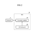
- the MCU includes a pulse pattern controller and an OCV setting unit.
- the pulse pattern controller counts the plurality of battery pulse patterns and stores a maximum peak voltage and a minimum peak voltage of a detected pulse pattern including at least the last pulse among the plurality of counted pulse patterns.
- the OCV setting unit calculates an average value of the maximum peak voltage and the minimum peak voltage of the detected pulse pattern, and sets the average value to an OCV.
- the average comprises an average of the maximum peak voltage and the minimum peak voltage of the at least one pulse pattern.
- the plurality of pulse patterns may comprise 10 pulse patterns.
- the average comprises an average of the maximum and minimum peak voltages of a 10th pulse pattern. More preferably, the average comprises an average of the maximum and minimum peak voltages of an 8th, a 9th, and a 10th pulse pattern.
- the MCU may generate the charge/discharge pulse pattern waveform while the vehicle is operating and/or while the vehicle is accelerating. Also, the MCU may generate the charge/discharge pulse pattern waveform while the battery is under a load.
- a driving method is provided to a battery management system for setting an OCV of a battery.
- the driving method includes: determining whether a battery is fully charged or fully discharged, and charging/discharging the battery to a predetermined SOC level of the battery; generating a plurality of battery charge/discharge pulse patterns, and counting the pulse patterns; and calculating an average value of a maximum peak voltage and a minimum peak voltage of a detected pulse pattern including at least the last pulse, and setting the average value to an OCV.
- the battery charge/discharge pulse pattern waveform is formed of a plurality of pulse patterns generated by repeating charge and discharge of the battery once.
- the SOC of the battery may be estimated from the OCV setting.
- the plurality of pulse patterns comprises 10 pulses.
- the at least one detected pulse pattern comprises an 8th, a 9th, and the last pulse pattern.
- the average value comprises an average of the maximum peak voltages and the minimum peak voltages of the 8th, the 9th, and the last pulse pattern.
- the average value comprises an average of all of the maximum peak voltages and the minimum peak voltages of the plurality of pulse patterns.
- the driving method may further comprise storing the maximum peak voltage and the minimum peak voltage of the at least one detected pulse pattern.
- FIG. 1 shows a diagram representing a battery, a battery management system (BMS), and peripheral devices of the BMS according to aspects of the present invention.
- the hybrid electric vehicle system includes a battery management system 1, a battery 2, a current sensor 3, a cooling fan 4, a fuse 5, a main switch 6, a motor control unit (MTCU) 7, an inverter 8, and a motor generator 9.
- the battery 2 includes a plurality of sub-packs 2a to 2h having a plurality of battery cells coupled in series, a first output terminal 2_OUT1, a second output terminal 2_OUT2, and a safety switch 2_SW.
- the sub-packs 2a to 2h are coupled in series but need not be limited thereto.
- the sub-packs 2a to 2h may be coupled in series with another component or device disposed therebetween.
- the safety switch 2 SW is disposed between the sub-pack 2d and the sub-pack 2e. While 8 sub-packs 2a to 2h are exemplified and each sub-pack is a group of a plurality of battery cells according to aspects of the present invention, it is not limited thereto.
- the battery 2 may include more or fewer sub-packs and battery cells, both of which may be arranged in series or parallel.
- the safety switch 2_SW is manually turned on/off to guarantee the safety of a worker when performing operations on the battery or replacing the battery.
- the safety switch 2_SW is provided between the sub-pack 2d and the sub-pack 2e but is not limited thereto.
- the first output terminal 2_OUT1 and the second output terminal 2_OUT2 are coupled to the inverter 8 via the current sensor 2 and the fuse 5 and the main switch 6, respectively.
- the current sensor 3 measures an output current of the battery 2 and outputs the measured output current to a sensing unit 10 of the BMS 1.
- the current sensor 3 may be a hall current transformer (Hall CT) that uses the Hall Effect via a hall element to measure a current and output an analog current signal corresponding to the measured current value.
- the current sensor 3 may also be an ammeter disposed in a load line or a shunt resistor, which outputs a voltage signal corresponding to a current value through a resistor inserted in the load line.
- the cooling fan 4 cools down heat generated by charging and discharging the battery 2 in response to a control signal from the BMS 1.
- the cooling fan 4 prevents the battery 2 and the charging/discharging efficiency thereof from deteriorating due to temperature increases.
- the fuse 5 prevents an overflow current, which may be caused by a short circuit of the battery 2, from being transmitted to the battery 2. That is, when an over-current is generated, the fuse 5 is disconnects or breaks the circuit so as to interrupt the current from overflowing and damaging the battery 2.
- the main switch 6 turns the battery 2 on and off in response to the control signals of the BMS 1 or control signals of the MTCU 7.
- the main switch 6 further protects the battery 2 from unusual phenomena, such as an overflowing voltage, an overflowing current, and high temperatures.
- the BMS 1 includes a sensing unit 10, a micro control unit (MCU) 20, an internal power supplier 30, a cell balance unit 40, a storage unit 50, a communication unit 60, a protection circuit unit 70, a power-on reset unit 80, and an external interface 90.
- MCU micro control unit
- the BMS 1 includes a sensing unit 10, a micro control unit (MCU) 20, an internal power supplier 30, a cell balance unit 40, a storage unit 50, a communication unit 60, a protection circuit unit 70, a power-on reset unit 80, and an external interface 90.
- MCU micro control unit
- the sensing unit 10 measures a voltage of the battery and transmits the measured voltage to the MCU 20.
- a voltage at an output terminal of the battery will be referred to as a battery voltage.
- the sensing unit 10 may also measure a current of the battery 2 and transmit the measured current to the MCU 20.
- the MCU 20 determines a state of charge (SOC) of the battery 2 based on the battery voltage transmitted from the sensing unit 10, and generates information that indicates the SOC of the battery 2. Then, the MCU 20 transmits the generated information to the MTCU 7 of the vehicle.
- SOC state of charge
- the MCU 20 controls a charge or discharge of the battery 2 by transmitting to the battery 2 a predetermined number of battery charge/discharge pulse pattern waveforms, such that a voltage of the battery 2 can have a predetermined number of maximum and minimum peaks, in order to measure an accurate OCV of the battery 2.
- the alternating charging/discharging of the battery according to the predetermined number of pulse pattern waveforms has the purpose of reducing polarization (or polarized resistance) of the battery 2, then the MCU 20 calculates an accurate OCV by using a portion of the pulse pattern waveforms.
- the MCU 20 sets an OCV setting from which an accurate SOC of the battery is determined by measuring and calculating a voltage of a predetermined number of pulse patterns of a battery charge/discharge pulse pattern waveform generated while the vehicle is being operated.
- the internal power supplier 30 supplies power to the BMS 1 by using a backup battery (not shown).
- the cell balance unit 40 balances the SOC of each cell in the battery 2. That is, cells relatively more charged are discharged, and cells relatively less charged are charged.
- the storage unit 50 stores data of the current SOC and a current state of health (SOH) when the power source of the BMS 1 is turned off.
- the communication unit 60 communicates with the MTCU 7 of the vehicle.
- the protection circuit unit 70 uses firmware elements to protect the battery 2 from shocks, overflowing currents, and low voltages.
- the power-on reset unit 80 resets the overall system when the power source of the BMS 1 is turned on.
- the external interface 90 couples BMS 1 auxiliary devices, such as the cooling fan 4 and the main switch 6, to the MCU 20. While the cooling fan 4 and the main switch 6 are shown as assistance devices for the BMS 1, the BMS 1 is not limited thereto. For example, other auxiliary devices may be included or the present auxiliary devices may be excluded.
- the MTCU 7 determines a torque state based on information from an accelerator, a brake, and a vehicle speed, and controls an output of the motor generator 9 so that the output corresponds to torque information. That is, the MTCU 7 controls a switching operation of the inverter 8, and controls the output of the motor generator 9 so that the output corresponds to the torque information.
- the MTCU 7 receives the SOC of the battery 2 from the MCU 20 through the communication unit 60, and controls the SOC level of the battery 2 toward a target level (e.g., 55%). For example, when the SOC level transmitted from the MCU 20 is lower than 55%, the MTCU 7 controls a switch to control the inverter 8 so as to output power toward the battery 2 and charge the battery 2.
- the MTCU 7 controls the switch of the inverter 8 to output the power toward the motor generator 9 and discharge the battery 2. In such case, current flows from the battery 2 to power the vehicle.
- the inverter 8 controls the battery 2 to be charged or discharged in response to the control signal from the MTCU 7.
- the motor generator 9 uses the electrical energy of the battery to drive the vehicle based on the torque information transmitted from the MTCU 7.
- FIG. 2 shows a schematic diagram of the MCU 20 of the BMS 1 of FIG. 1.
- the MCU 20 includes a pulse pattern controller 210 and an OCV setting unit 220.
- the pulse pattern controller 210 determines whether the battery 2 is fully charged or fully discharged, and discharges the battery 2 to a SOC value of 60% at a 1C rate when the battery 2 is fully charged and charges the battery 2 to a SOC value of 60% at a 1C rate when the battery 2 is fully discharged.
- a charge current and a discharge current of a battery are measured in C-rate, which represents the amount of charge/discharge current required for fully charging/discharging the battery within one hour.
- the pulse pattern controller 210 charges or discharges the battery 2 to a SOC value of 60% at a 1C rate, and controls the charge/discharge operation of the battery 2 so as to control a voltage of the battery 2 to have a plurality of pulse pattern waveforms.
- each of the plurality of pulse pattern waveforms is formed of a plurality of pulse patterns, each of which is discharging and charging the battery 2 once.
- the pulse pattern controller 210 eliminates polarization and internal resistance in the battery 2, by using the battery charge/discharge pulse pattern waveform.
- the pulse pattern controller 210 controls a SOC of the battery 2 toward a constant level when the battery 2 is fully charged or fully discharged and controls the charge/discharge operation of the battery 2 so as to generate the plurality of battery pulse patterns. In more detail, the pulse pattern controller 210 determines whether the battery 2 is fully charged or fully discharged, discharges the battery 2 to a SOC value of 60% at a 1C rate when the battery 2 is fully charged, and charges the battery 2 to a SOC value of 60% at a 1C rate when the battery 2 is fully discharged.
- the pulse pattern controller 210 controls a battery charge/discharge pulse pattern waveform after the battery 2 is charged or discharged.
- each of the plurality of battery charge/discharge pulse pattern waveforms is formed of 10 pulse patterns, and each pulse pattern repeats charge and discharge of the battery 2 once.
- the pulse pattern controller 210 counts a waveform formed of 10 pulses, from the first pulse to the 10th pulse, and stops counting after the pulse pattern controller 210 counts 10 times.
- the pulse pattern controller stores a maximum peak voltage and a minimum peak voltage among battery voltages of the detected pulse patterns.
- the detected pulse pattern may include at least the last pulse among the plurality of pulse patterns.
- the OCV setting unit 220 adds the maximum peak voltage and the minimum peak voltage of pulse pattern from the 8th detected pulse pattern to the 10th detected pulse pattern transmitted from the pulse pattern controller 210, and calculates an average of the maximum and minimum peak voltages. Then, the OCV setting unit 220 sets the calculated average value to an OCV setting.
- the OCV setting unit 220 integrates a voltage of a detected pulse pattern that may include at least the last pulse and divides the integration result by time, and then sets a division result to the OCV setting.
- the OCV setting unit 220 may set an average value of maximum and minimum peak voltages of three detected pulse patterns among the plurality of pulse patterns, but this is not restrictive.
- the OCV setting unit 220 may use the last pulse or the OCV setting unit 220 may average several previous pulses to set the OCV setting.
- the described embodiment may be modified in various different ways.
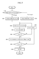
- FIG. 3 is a flowchart representing a driving method of the battery management system (BMS 1) according to aspects of the present invention.
- the MCU 20 of the BMS 1 determines whether the battery 2 is fully charged or fully discharged. When it is determined in operation (S100) that the battery 2 is fully charged, the MCU 20 discharges the fully charged battery to a predetermined SOC level of 60% at a 1C rate in operation (S200). When it is determined in operation (S100) that the battery 2 is fully discharged, the MCU 20 charges the fully discharged battery 2 to the predetermined SOC level of 60% at a 1C rate in operation (S300).
- a charge current and a discharge current of a battery is measured in C-rate, which represents the amount of charge/discharge current required to fully charge/discharge the battery within one hour.
- the predetermined SOC level needs not be 60%.
- the MCU 20 controls a voltage of the battery 2 by applying a battery charge/discharge pulse pattern waveform in operation (S400).
- the battery charge/discharge pulse pattern waveform is formed of 10 pulse patterns, wherein each of the 10 pulse patterns charges the battery 2 and discharges the battery 2 once.
- the MCU 20 counts the battery charge/discharge pulse patterns in operation (S500). Then, the MCU 20 determines whether it has counted the pulse pattern more than 8 times in operation (S600). When it is determined in operation (S600) that the MCU 20 has counted the pulse pattern fewer than 8 times, the MCU 20 increments the number of counting by 1, in operation (S700). Then, the MCU 20 returns to the operation (S400).
- the MCU 200 sets the 8th pulse pattern to the 10th pulse pattern as detected pulse patterns, and stores a maximum peak voltage and a minimum peak voltage of each pulse pattern of the detected pulse patterns in operation (S800). Then, whether counting of the pulse pattern has been performed 10 times is determined in operation (S900). When a result of the determination in operation (S900) shows that the counting of the pulse pattern has been performed less than 10 times, the counting of the pulse pattern is performed one more time and incremented in operation (S700). Then, the process is returned to operation (S400).
- the MCU 200 calculates an average value of the maximum peak voltages and the minimum peak voltages from the detected pulse patterns stored in operation (S800) and the average value (of the maximum and minimum voltages) is set as the OCV setting, in operation (S1000). The OCV setting is then used to estimate the SOC of the battery 2.
- the driving method is described as averaging the maximum and minimum peak voltages of the 8th through 10th pulse patterns
- the MCU 200 is not limited thereto.
- the OCV setting may be determined by only averaging the minimum peak voltages of the 8th through 10th pulse patterns.
- only the maximum and minimum peak voltages of the 10th pulse pattern may be averaged to determine the OCV setting from which the SOC of the battery 2 is determined.
- the battery management system and the driving method according to aspects of the present invention use a detected pulse pattern to set an OCV setting from which a more accurate SOC may be estimated.
- the battery management system determines whether the battery is in the fully-charged state or in the fully-discharged state, and charges or discharges the battery to a predetermined SOC level of 60% at a 1C rate according to a result of the determination. Then, the battery management system controls a charge/discharge pulse pattern waveform of the battery and counts a pulse pattern. A maximum peak voltage and a minimum peak voltage of each counted pulse pattern is stored, and an average value of maximum peak voltages and the minimum peak voltages of the 8th counted pulse pattern to the 10th counted pulse pattern is calculated. The calculated average value is set as the OCV setting.
- the polarization voltage can be decreased in order to reduce the polarization phenomenon.
- the pulse pattern voltage is compulsorily applied inside the battery 2 and the polarization voltage can be decreased by the pulse pattern voltage.
- the more pulses are applied to the battery the more the polarization voltage can be decreased.
- the period of applying the pulses is restricted. Therefore, to exactly calculate the OCV, the present invention averages only the last pulses. Accordingly, an accurate OCV can be set while the vehicle is operating and/or accelerating or while the battery is under a load. Accordingly, the battery management system and the driving method of the battery management system can measure an accurate SOC.
- errors in SOC estimation can be reduced by reducing an error that may be generated when setting an OCV setting, and therefore overcharge and over-discharge of the battery can be prevented.
Abstract
Description
- Aspects of the present invention relate to a battery management system. More particularly, aspects of the present invention relate to a battery management system that can be used in a vehicle using electrical energy.
- Vehicles with internal combustion engines using gasoline or diesel have caused serious air pollution. Accordingly, various attempts to develop electric or hybrid vehicles have recently been made to reduce such air pollution.
- An electric vehicle uses an electric motor operating by electrical energy output from a battery. Since the electric vehicle generally uses a battery formed of at least one battery pack including a plurality of rechargeable/dischargeable (or secondary) cells, there is merit in that the electric vehicle generates no emission gases and produces less noise.
- "Hybrid vehicle" commonly refers to a gasoline-electric hybrid vehicle that uses gasoline to power an internal-combustion engine and a battery to power an electric motor. Recently, hybrid vehicles using an internal-combustion engine and fuel cells and hybrid vehicles using a battery and fuel cells have been developed. The fuel cells directly produce electrical energy through a chemical reaction between hydrogen and oxygen, which are continuously provided.
- Since battery performance directly affects the performance of the vehicle using electrical energy, it is required that each battery cell has great performance. Also, a battery management system (BMS) is necessary to measure a voltage and a current of the overall battery to efficiently manage charging/discharging operations of each battery cell therein.
- In general, the battery management system needs to measure an accurate open circuit voltage (OCV) so as to measure an accurate SOC. When a vehicle is driven at a constant speed or is stopped, and a charging and discharging operation of the battery is not performed, the OCV may not be accurately measured as polarization and internal resistance in the battery, is generated. A length of time to correct the polarization is required to accurately measure the OCV. However, it is difficult to guarantee such a time when a hybrid vehicle is driven. Accordingly, an error in measuring the OCV measured after only a short time or before the correction of the polarization may cause an error in the calculation of the SOC.
- The above information disclosed in this Background section is only for enhancement of understanding of the background of the invention and therefore it may contain information that does not form the prior art that is already known in this country to a person of ordinary skill in the art.
- Aspects of the present invention have been made in an effort to provide a battery management system having advantages of estimating an accurate state of charge (SOC) by accurately measuring an open circuit voltage (OCV), and a driving method thereof.
- A battery management system according to an embodiment of the present invention includes a sensing unit and a main control unit (MCU). The sensing unit measures a voltage of a battery. The MCU controls a charge/discharge of the battery, generates charge/discharge pulse pattern waveforms, measures a voltage value of at least one pulse pattern among the charge/discharge pulse pattern waveforms, and sets an average of the measured voltage to an open circuit voltage (OCV). A State of Charge (SOC) of the battery is estimated from the OCV setting. The sensing unit transmits the at least one measured voltage value to the MCU.
- The MCU may charge the battery to a predetermined level if the battery is fully discharged, and the MCU may discharge the battery to the predetermined level if the battery is fully charged. Preferably, the predetermined SOC level is 60%. Preferably, the MCU generates the charge/discharge pulse pattern waveform after the battery is charged/discharged to the predetermined level.
- Herein, the battery charge/discharge pulse pattern waveform is formed of a plurality of pulse patterns, each formed by repeating charge and discharge of the battery once.
- In addition, the MCU includes a pulse pattern controller and an OCV setting unit. The pulse pattern controller counts the plurality of battery pulse patterns and stores a maximum peak voltage and a minimum peak voltage of a detected pulse pattern including at least the last pulse among the plurality of counted pulse patterns. The OCV setting unit calculates an average value of the maximum peak voltage and the minimum peak voltage of the detected pulse pattern, and sets the average value to an OCV.
- Preferably, the average comprises an average of the maximum peak voltage and the minimum peak voltage of the at least one pulse pattern. The plurality of pulse patterns may comprise 10 pulse patterns.
- Preferably, the average comprises an average of the maximum and minimum peak voltages of a 10th pulse pattern. More preferably, the average comprises an average of the maximum and minimum peak voltages of an 8th, a 9th, and a 10th pulse pattern.
- The MCU may generate the charge/discharge pulse pattern waveform while the vehicle is operating and/or while the vehicle is accelerating. Also, the MCU may generate the charge/discharge pulse pattern waveform while the battery is under a load.
- A driving method according to another embodiment of the present invention is provided to a battery management system for setting an OCV of a battery. The driving method includes: determining whether a battery is fully charged or fully discharged, and charging/discharging the battery to a predetermined SOC level of the battery; generating a plurality of battery charge/discharge pulse patterns, and counting the pulse patterns; and calculating an average value of a maximum peak voltage and a minimum peak voltage of a detected pulse pattern including at least the last pulse, and setting the average value to an OCV.
- In addition, the battery charge/discharge pulse pattern waveform is formed of a plurality of pulse patterns generated by repeating charge and discharge of the battery once.
- The SOC of the battery may be estimated from the OCV setting.
- Preferably, the plurality of pulse patterns comprises 10 pulses. Preferably, the at least one detected pulse pattern comprises an 8th, a 9th, and the last pulse pattern. Preferably, the average value comprises an average of the maximum peak voltages and the minimum peak voltages of the 8th, the 9th, and the last pulse pattern. Alternatively, the average value comprises an average of all of the maximum peak voltages and the minimum peak voltages of the plurality of pulse patterns.
- The driving method may further comprise storing the maximum peak voltage and the minimum peak voltage of the at least one detected pulse pattern.
- Additional aspects and/or advantages of the invention will be set forth in part in the description which follows and, in part, will be obvious from the description, or may be learned by practice of the invention.
- These and/or other aspects and advantages of the invention will become apparent and more readily appreciated from the following description of the embodiments, taken in conjunction with the accompanying drawings of which:
- FIG. 1 shows a diagram representing a battery, a battery management system (BMS), and peripheral devices of the BMS;
- FIG. 2 shows a schematic diagram of the MCU of the BMS of FIG. 1; and
- FIG. 3 is a flowchart representing a driving method of the BMS according to aspects of the present invention.
- Reference will now be made in detail to the present embodiments of the present invention, examples of which are illustrated in the accompanying drawings, wherein like reference numerals refer to the like elements throughout. The embodiments are described below in order to explain the present invention by referring to the figures.
- FIG. 1 shows a diagram representing a battery, a battery management system (BMS), and peripheral devices of the BMS according to aspects of the present invention. As shown in FIG. 1, the hybrid electric vehicle system according to aspects of the present invention includes a
battery management system 1, abattery 2, acurrent sensor 3, a cooling fan 4, afuse 5, a main switch 6, a motor control unit (MTCU) 7, aninverter 8, and amotor generator 9. - The
battery 2 includes a plurality ofsub-packs 2a to 2h having a plurality of battery cells coupled in series, a first output terminal 2_OUT1, a second output terminal 2_OUT2, and a safety switch 2_SW. Thesub-packs 2a to 2h are coupled in series but need not be limited thereto. Thesub-packs 2a to 2h may be coupled in series with another component or device disposed therebetween. Thesafety switch 2 SW is disposed between thesub-pack 2d and thesub-pack 2e. While 8sub-packs 2a to 2h are exemplified and each sub-pack is a group of a plurality of battery cells according to aspects of the present invention, it is not limited thereto. Thebattery 2 may include more or fewer sub-packs and battery cells, both of which may be arranged in series or parallel. The safety switch 2_SW is manually turned on/off to guarantee the safety of a worker when performing operations on the battery or replacing the battery. The safety switch 2_SW is provided between the sub-pack 2d and the sub-pack 2e but is not limited thereto. The first output terminal 2_OUT1 and the second output terminal 2_OUT2 are coupled to theinverter 8 via thecurrent sensor 2 and thefuse 5 and the main switch 6, respectively. - The
current sensor 3 measures an output current of thebattery 2 and outputs the measured output current to asensing unit 10 of theBMS 1. In further detail, thecurrent sensor 3 may be a hall current transformer (Hall CT) that uses the Hall Effect via a hall element to measure a current and output an analog current signal corresponding to the measured current value. Thecurrent sensor 3 may also be an ammeter disposed in a load line or a shunt resistor, which outputs a voltage signal corresponding to a current value through a resistor inserted in the load line. - The cooling fan 4 cools down heat generated by charging and discharging the
battery 2 in response to a control signal from theBMS 1. The cooling fan 4 prevents thebattery 2 and the charging/discharging efficiency thereof from deteriorating due to temperature increases. - The
fuse 5 prevents an overflow current, which may be caused by a short circuit of thebattery 2, from being transmitted to thebattery 2. That is, when an over-current is generated, thefuse 5 is disconnects or breaks the circuit so as to interrupt the current from overflowing and damaging thebattery 2. - The main switch 6 turns the
battery 2 on and off in response to the control signals of theBMS 1 or control signals of the MTCU 7. The main switch 6 further protects thebattery 2 from unusual phenomena, such as an overflowing voltage, an overflowing current, and high temperatures. - The
BMS 1 includes asensing unit 10, a micro control unit (MCU) 20, aninternal power supplier 30, acell balance unit 40, astorage unit 50, acommunication unit 60, aprotection circuit unit 70, a power-onreset unit 80, and anexternal interface 90. - The
sensing unit 10 measures a voltage of the battery and transmits the measured voltage to theMCU 20. Hereinafter, a voltage at an output terminal of the battery will be referred to as a battery voltage. Thesensing unit 10 may also measure a current of thebattery 2 and transmit the measured current to theMCU 20. - The
MCU 20 determines a state of charge (SOC) of thebattery 2 based on the battery voltage transmitted from thesensing unit 10, and generates information that indicates the SOC of thebattery 2. Then, theMCU 20 transmits the generated information to the MTCU 7 of the vehicle. In addition, theMCU 20 controls a charge or discharge of thebattery 2 by transmitting to thebattery 2 a predetermined number of battery charge/discharge pulse pattern waveforms, such that a voltage of thebattery 2 can have a predetermined number of maximum and minimum peaks, in order to measure an accurate OCV of the battery 2.The alternating charging/discharging of the battery according to the predetermined number of pulse pattern waveforms has the purpose of reducing polarization (or polarized resistance) of thebattery 2, then theMCU 20 calculates an accurate OCV by using a portion of the pulse pattern waveforms. A voltage drop due to internal resistance has not to be taken into account, because no current flows inside thebattery 2 during the period of applying the pulse pattern waveform to the battery 2.Therefore, theMCU 20 sets an OCV setting from which an accurate SOC of the battery is determined by measuring and calculating a voltage of a predetermined number of pulse patterns of a battery charge/discharge pulse pattern waveform generated while the vehicle is being operated. - The
internal power supplier 30 supplies power to theBMS 1 by using a backup battery (not shown). Thecell balance unit 40 balances the SOC of each cell in thebattery 2. That is, cells relatively more charged are discharged, and cells relatively less charged are charged. Thestorage unit 50 stores data of the current SOC and a current state of health (SOH) when the power source of theBMS 1 is turned off. - The
communication unit 60 communicates with the MTCU 7 of the vehicle. Theprotection circuit unit 70 uses firmware elements to protect thebattery 2 from shocks, overflowing currents, and low voltages. The power-onreset unit 80 resets the overall system when the power source of theBMS 1 is turned on. Theexternal interface 90 couples BMS 1 auxiliary devices, such as the cooling fan 4 and the main switch 6, to theMCU 20. While the cooling fan 4 and the main switch 6 are shown as assistance devices for theBMS 1, theBMS 1 is not limited thereto. For example, other auxiliary devices may be included or the present auxiliary devices may be excluded. - The MTCU 7 determines a torque state based on information from an accelerator, a brake, and a vehicle speed, and controls an output of the
motor generator 9 so that the output corresponds to torque information. That is, the MTCU 7 controls a switching operation of theinverter 8, and controls the output of themotor generator 9 so that the output corresponds to the torque information. In addition, the MTCU 7 receives the SOC of thebattery 2 from theMCU 20 through thecommunication unit 60, and controls the SOC level of thebattery 2 toward a target level (e.g., 55%). For example, when the SOC level transmitted from theMCU 20 is lower than 55%, the MTCU 7 controls a switch to control theinverter 8 so as to output power toward thebattery 2 and charge thebattery 2. In such case, current flows toward thebattery 2 to charge thebattery 2. When the SOC level is greater than 55%, the MTCU 7 controls the switch of theinverter 8 to output the power toward themotor generator 9 and discharge thebattery 2. In such case, current flows from thebattery 2 to power the vehicle. - The
inverter 8 controls thebattery 2 to be charged or discharged in response to the control signal from the MTCU 7. Themotor generator 9 uses the electrical energy of the battery to drive the vehicle based on the torque information transmitted from the MTCU 7. - FIG. 2 shows a schematic diagram of the
MCU 20 of theBMS 1 of FIG. 1. As shown in FIG. 2, theMCU 20 includes apulse pattern controller 210 and anOCV setting unit 220. - The
pulse pattern controller 210 determines whether thebattery 2 is fully charged or fully discharged, and discharges thebattery 2 to a SOC value of 60% at a 1C rate when thebattery 2 is fully charged and charges thebattery 2 to a SOC value of 60% at a 1C rate when thebattery 2 is fully discharged. Herein, a charge current and a discharge current of a battery are measured in C-rate, which represents the amount of charge/discharge current required for fully charging/discharging the battery within one hour. Thepulse pattern controller 210 charges or discharges thebattery 2 to a SOC value of 60% at a 1C rate, and controls the charge/discharge operation of thebattery 2 so as to control a voltage of thebattery 2 to have a plurality of pulse pattern waveforms. - In this case, each of the plurality of pulse pattern waveforms is formed of a plurality of pulse patterns, each of which is discharging and charging the
battery 2 once. In addition, thepulse pattern controller 210 eliminates polarization and internal resistance in thebattery 2, by using the battery charge/discharge pulse pattern waveform. - The
pulse pattern controller 210 controls a SOC of thebattery 2 toward a constant level when thebattery 2 is fully charged or fully discharged and controls the charge/discharge operation of thebattery 2 so as to generate the plurality of battery pulse patterns. In more detail, thepulse pattern controller 210 determines whether thebattery 2 is fully charged or fully discharged, discharges thebattery 2 to a SOC value of 60% at a 1C rate when thebattery 2 is fully charged, and charges thebattery 2 to a SOC value of 60% at a 1C rate when thebattery 2 is fully discharged. - In addition, the
pulse pattern controller 210 controls a battery charge/discharge pulse pattern waveform after thebattery 2 is charged or discharged. In such case, each of the plurality of battery charge/discharge pulse pattern waveforms is formed of 10 pulse patterns, and each pulse pattern repeats charge and discharge of thebattery 2 once. Thepulse pattern controller 210 counts a waveform formed of 10 pulses, from the first pulse to the 10th pulse, and stops counting after thepulse pattern controller 210 counts 10 times. Herein, when the number of the pulse waveforms is greater than or equal to 8, the pulse pattern controller stores a maximum peak voltage and a minimum peak voltage among battery voltages of the detected pulse patterns. The detected pulse pattern may include at least the last pulse among the plurality of pulse patterns. - The
OCV setting unit 220 adds the maximum peak voltage and the minimum peak voltage of pulse pattern from the 8th detected pulse pattern to the 10th detected pulse pattern transmitted from thepulse pattern controller 210, and calculates an average of the maximum and minimum peak voltages. Then, theOCV setting unit 220 sets the calculated average value to an OCV setting. - According to the OCV setting method of the
BMS 1, theOCV setting unit 220 integrates a voltage of a detected pulse pattern that may include at least the last pulse and divides the integration result by time, and then sets a division result to the OCV setting. - That is, the
OCV setting unit 220 according to aspects of the present invention may set an average value of maximum and minimum peak voltages of three detected pulse patterns among the plurality of pulse patterns, but this is not restrictive. TheOCV setting unit 220 may use the last pulse or theOCV setting unit 220 may average several previous pulses to set the OCV setting. In addition, the described embodiment may be modified in various different ways. - FIG. 3 is a flowchart representing a driving method of the battery management system (BMS 1) according to aspects of the present invention. In operation (S100), the
MCU 20 of theBMS 1 determines whether thebattery 2 is fully charged or fully discharged. When it is determined in operation (S100) that thebattery 2 is fully charged, theMCU 20 discharges the fully charged battery to a predetermined SOC level of 60% at a 1C rate in operation (S200). When it is determined in operation (S100) that thebattery 2 is fully discharged, theMCU 20 charges the fully dischargedbattery 2 to the predetermined SOC level of 60% at a 1C rate in operation (S300). Herein, a charge current and a discharge current of a battery is measured in C-rate, which represents the amount of charge/discharge current required to fully charge/discharge the battery within one hour. However, the predetermined SOC level needs not be 60%. - After charging or discharging the
battery 2 to the predetermined SOC level (e.g. 60%), theMCU 20 controls a voltage of thebattery 2 by applying a battery charge/discharge pulse pattern waveform in operation (S400). In this case, the battery charge/discharge pulse pattern waveform is formed of 10 pulse patterns, wherein each of the 10 pulse patterns charges thebattery 2 and discharges thebattery 2 once. TheMCU 20 counts the battery charge/discharge pulse patterns in operation (S500). Then, theMCU 20 determines whether it has counted the pulse pattern more than 8 times in operation (S600). When it is determined in operation (S600) that theMCU 20 has counted the pulse pattern fewer than 8 times, theMCU 20 increments the number of counting by 1, in operation (S700). Then, theMCU 20 returns to the operation (S400). - When it is determined in operation (S600) that the
MCU 20 has counted the pulse pattern at least 8 times, theMCU 200 sets the 8th pulse pattern to the 10th pulse pattern as detected pulse patterns, and stores a maximum peak voltage and a minimum peak voltage of each pulse pattern of the detected pulse patterns in operation (S800). Then, whether counting of the pulse pattern has been performed 10 times is determined in operation (S900). When a result of the determination in operation (S900) shows that the counting of the pulse pattern has been performed less than 10 times, the counting of the pulse pattern is performed one more time and incremented in operation (S700). Then, the process is returned to operation (S400). - When a result of the determination in operation (S900) shows that the counting of the pulse pattern has been performed 10 times, the
MCU 200 calculates an average value of the maximum peak voltages and the minimum peak voltages from the detected pulse patterns stored in operation (S800) and the average value (of the maximum and minimum voltages) is set as the OCV setting, in operation (S1000). The OCV setting is then used to estimate the SOC of thebattery 2. - Although the driving method is described as averaging the maximum and minimum peak voltages of the 8th through 10th pulse patterns, the
MCU 200 is not limited thereto. For example, the OCV setting may be determined by only averaging the minimum peak voltages of the 8th through 10th pulse patterns. Or, only the maximum and minimum peak voltages of the 10th pulse pattern may be averaged to determine the OCV setting from which the SOC of thebattery 2 is determined. - As described, the battery management system and the driving method according to aspects of the present invention use a detected pulse pattern to set an OCV setting from which a more accurate SOC may be estimated. The battery management system determines whether the battery is in the fully-charged state or in the fully-discharged state, and charges or discharges the battery to a predetermined SOC level of 60% at a 1C rate according to a result of the determination. Then, the battery management system controls a charge/discharge pulse pattern waveform of the battery and counts a pulse pattern. A maximum peak voltage and a minimum peak voltage of each counted pulse pattern is stored, and an average value of maximum peak voltages and the minimum peak voltages of the 8th counted pulse pattern to the 10th counted pulse pattern is calculated. The calculated average value is set as the OCV setting.
- According to aspects of the present invention, the polarization voltage can be decreased in order to reduce the polarization phenomenon. The pulse pattern voltage is compulsorily applied inside the
battery 2 and the polarization voltage can be decreased by the pulse pattern voltage. The more pulses are applied to the battery, the more the polarization voltage can be decreased. However, the period of applying the pulses is restricted. Therefore, to exactly calculate the OCV, the present invention averages only the last pulses. Accordingly, an accurate OCV can be set while the vehicle is operating and/or accelerating or while the battery is under a load. Accordingly, the battery management system and the driving method of the battery management system can measure an accurate SOC. - In addition, errors in SOC estimation can be reduced by reducing an error that may be generated when setting an OCV setting, and therefore overcharge and over-discharge of the battery can be prevented.
Claims (20)
- A driving method of a battery management system (1) to control the charge/discharge of a battery (2), the driving method comprising:determining whether the battery (2) is fully charged or fully discharged;charging/discharging the battery (2) to a state of charge (SOC) of a predetermined level;generating a battery charge/discharge pulse pattern waveform comprising a plurality of pulse patterns;counting the pulse patterns;calculating an average value of a maximum peak voltage and a minimum peak voltage of at least one detected pulse pattern including the last pulse pattern; andsetting the average value to an OCV setting.
- The driving method of claim 1, wherein each of the plurality of pulse patterns charges and discharges the battery (2) once.
- The driving method of one of the preceding claims, further comprising estimating the SOC of the battery (2) from the OCV setting.
- The driving method of one of the preceding claims, wherein the plurality of pulse patterns comprises 10 pulses.
- The driving method of claim 4, wherein the at least one detected pulse pattern comprises an 8th, a 9th, and the last pulse pattern.
- The driving method of claim 5, wherein the average value comprises an average of the maximum peak voltages and the minimum peak voltages of the 8th, the 9th, and the last pulse pattern.
- The driving method of one of the preceding claims, further comprising storing the maximum peak voltage and the minimum peak voltage of the at least one detected pulse pattern.
- The driving method of one of claims 1-3, wherein the average value comprises an average of all of the maximum peak voltages and the minimum peak voltages of the plurality of pulse patterns.
- A battery management system (1) for a vehicle, comprising:a sensing unit (10) to measure a voltage of a battery (2); anda main control unit MCU (20) to control a charge/discharge of the battery (2), to generate a charge/discharge pulse pattern waveform comprising a plurality of pulse patterns, to measure at least one voltage value of at least one pulse pattern, and to set an average of the at least one measured voltage value to an open circuit voltage (OCV) setting from which a state of charge (SOC) of the battery (2) is estimated,wherein the sensing unit (10) transmits the at least one measured voltage value to the MCU (20).
- The battery management system of claim 9, wherein the MCU (20) charges the battery (2) to a predetermined level if the battery is fully discharged, and the MCU (20) discharges the battery (2) to the predetermined level if the battery (2) is fully charged.
- The battery management system of claim 10, wherein the predetermined SOC level is 60%.
- The battery management system of one of claims 10 and 11,
wherein the MCU (20) generates the charge/discharge pulse pattern waveform after the battery (2) is charged/discharged to the predetermined level. - The battery management system of one of claims 9-12, wherein each of the plurality of pulse patterns charges and discharges the battery once.
- The battery management system of one of claims 9-13, wherein the MCU (20) comprises:a pulse pattern controller (210) to count a number of the pulse patterns and to store a maximum peak voltage and a minimum peak voltage of a detected pulse pattern including at least the last pulse pattern of the counted number of pulse patterns; andan OCV setting unit (220) to calculate an average value of the maximum peak voltage and the minimum peak voltage of the counted number of pulse patterns, and setting the average value to an OCV setting.
- The battery management system of claim 14, wherein the average comprises an average of the maximum peak voltage and the minimum peak voltage of the at least one pulse pattern.
- The battery management system of one of claims 9-15, wherein the plurality of pulse patterns comprises 10 pulse patterns.
- The battery management system of claim 16, wherein the average comprises an average of the maximum and minimum peak voltages of a 10th pulse pattern.
- The battery management system of claim 16, wherein the average comprises an average of the maximum and minimum peak voltages of an 8th, a 9th, and a 10th pulse pattern.
- The battery management system of one of claims 9-18, wherein the MCU (20) generates the charge/discharge pulse pattern waveform while the vehicle is operating and/or while the vehicle is accelerating.
- The battery management system of one of claims 9-19, wherein the MCU (20) generates the charge/discharge pulse pattern waveform while the battery (2) is under a load.
Applications Claiming Priority (1)
| Application Number | Priority Date | Filing Date | Title |
|---|---|---|---|
| KR1020060107224A KR100839384B1 (en) | 2006-11-01 | 2006-11-01 | Battery management system and driving method thereof |
Publications (3)
| Publication Number | Publication Date |
|---|---|
| EP1919060A2 true EP1919060A2 (en) | 2008-05-07 |
| EP1919060A3 EP1919060A3 (en) | 2008-05-21 |
| EP1919060B1 EP1919060B1 (en) | 2012-03-14 |
Family
ID=39137002
Family Applications (1)
| Application Number | Title | Priority Date | Filing Date |
|---|---|---|---|
| EP07119357A Expired - Fee Related EP1919060B1 (en) | 2006-11-01 | 2007-10-26 | Battery management system and driving method thereof |
Country Status (5)
| Country | Link |
|---|---|
| US (1) | US20080100265A1 (en) |
| EP (1) | EP1919060B1 (en) |
| JP (1) | JP4949086B2 (en) |
| KR (1) | KR100839384B1 (en) |
| CN (1) | CN101174710B (en) |
Cited By (2)
| Publication number | Priority date | Publication date | Assignee | Title |
|---|---|---|---|---|
| CN103802684A (en) * | 2012-11-03 | 2014-05-21 | 贺怀远 | Charging and discharging device of electric automobile |
| WO2018056567A1 (en) * | 2016-09-26 | 2018-03-29 | Samsung Electronics Co., Ltd. | Apparatus and method for battery management |
Families Citing this family (20)
| Publication number | Priority date | Publication date | Assignee | Title |
|---|---|---|---|---|
| KR100737003B1 (en) * | 2005-12-14 | 2007-07-09 | 현대자동차주식회사 | Method for determining optimal drive point in series and parallel hybrid car |
| US8264207B2 (en) * | 2007-10-16 | 2012-09-11 | Ford Global Technologies, Llc | Method and system for pulse charging an automotive battery |
| KR101187766B1 (en) * | 2008-08-08 | 2012-10-05 | 주식회사 엘지화학 | Apparatus and Method for cell balancing based on battery's voltage variation pattern |
| JP5448865B2 (en) * | 2010-01-18 | 2014-03-19 | 三菱重工業株式会社 | Battery system |
| JP5704108B2 (en) * | 2012-03-30 | 2015-04-22 | トヨタ自動車株式会社 | Battery system and estimation method |
| JP5704156B2 (en) * | 2012-12-25 | 2015-04-22 | 株式会社デンソー | Battery system |
| US20140350875A1 (en) * | 2013-05-27 | 2014-11-27 | Scott Allen Mullin | Relaxation model in real-time estimation of state-of-charge in lithium polymer batteries |
| US9915703B2 (en) | 2013-10-16 | 2018-03-13 | Ford Global Technologies, Llc | Voltage sensing system and method |
| CN103529394B (en) * | 2013-10-24 | 2015-09-09 | 国家电网公司 | A kind of energy storage system capacity pick-up unit and method |
| CN104714181B (en) * | 2013-12-11 | 2017-10-27 | 广州汽车集团股份有限公司 | It is a kind of to obtain voltage and the method and system of battery charge state relation |
| KR101630409B1 (en) * | 2014-06-11 | 2016-06-14 | 주식회사 엘지화학 | Apparatus and method for estimating battery state and battery pack using it |
| CN104527448B (en) * | 2015-01-04 | 2016-08-17 | 南车株洲电力机车有限公司 | A kind of voltage balance control method and system |
| CN104908605A (en) * | 2015-06-15 | 2015-09-16 | 王凤成 | BMS (Battery Management System) decentralized detection and centralized management system of modularized lithium batteries |
| JP6421986B2 (en) * | 2015-07-29 | 2018-11-14 | スズキ株式会社 | Secondary battery charging rate estimation method, charging rate estimation device, and soundness estimation device |
| KR102634814B1 (en) * | 2016-11-16 | 2024-02-07 | 삼성전자주식회사 | Method and apparatus for estimating battery state |
| CN106501732A (en) * | 2016-12-14 | 2017-03-15 | 中国电力科学研究院 | A kind of method and system for being estimated to Clock battery dump energy |
| CN108254691B (en) * | 2016-12-28 | 2021-10-01 | 硅谷实验室公司 | Method and apparatus for charge measurement in a system using a DC-DC converter of PFM |
| US10996281B2 (en) | 2016-12-28 | 2021-05-04 | Silicon Laboratories Inc. | Charge measurement calibration in a system using a pulse frequency modulated DC-DC converter |
| KR102458526B1 (en) * | 2018-02-07 | 2022-10-25 | 주식회사 엘지에너지솔루션 | Apparatus and method for estimating soc base on operating state of battery |
| JP2024510053A (en) * | 2022-02-18 | 2024-03-06 | 寧徳時代新能源科技股▲分▼有限公司 | Battery module charging system and its control method, device, unit and storage medium |
Citations (3)
| Publication number | Priority date | Publication date | Assignee | Title |
|---|---|---|---|---|
| US5523667A (en) * | 1992-01-27 | 1996-06-04 | Feldstein; Robert S. | Alkaline battery charger and method of operating same |
| US6154011A (en) * | 1997-09-15 | 2000-11-28 | Commonwealth Scientifc And Industrial Research Organisation | Charging of batteries |
| US20050099162A1 (en) * | 2003-11-06 | 2005-05-12 | Yi Ding | System and method for charging a battery |
Family Cites Families (6)
| Publication number | Priority date | Publication date | Assignee | Title |
|---|---|---|---|---|
| FR2421430A1 (en) * | 1978-03-29 | 1979-10-26 | Peugeot | DEVICE TO SIMULATE THE OPERATION OF AN ACCUMULATOR BATTERY, IN PARTICULAR A TRACTION BATTERY FOR AN ELECTRIC VEHICLE |
| FI112730B (en) * | 1995-09-05 | 2003-12-31 | Nokia Corp | Determination of the accumulator voltage between the charge and the charging device for accumulators |
| US6366056B1 (en) * | 1999-06-08 | 2002-04-02 | Enrev Corporation | Battery charger for lithium based batteries |
| KR100505382B1 (en) * | 2003-06-20 | 2005-08-02 | 주식회사 파워로직스 | Method for deciding battery soc amounting time of hev |
| US7442470B2 (en) * | 2004-10-12 | 2008-10-28 | Matsushita Electric Industrial Co., Ltd. | High power output non-aqueous electrolyte secondary battery |
| KR20060098146A (en) * | 2005-03-09 | 2006-09-18 | 주식회사 엘지화학 | Method of setting initial value of soc of battery using ocv temperature hysteresis |
-
2006
- 2006-11-01 KR KR1020060107224A patent/KR100839384B1/en not_active IP Right Cessation
-
2007
- 2007-03-13 JP JP2007063359A patent/JP4949086B2/en not_active Expired - Fee Related
- 2007-09-10 US US11/852,575 patent/US20080100265A1/en not_active Abandoned
- 2007-09-30 CN CN2007101514002A patent/CN101174710B/en not_active Expired - Fee Related
- 2007-10-26 EP EP07119357A patent/EP1919060B1/en not_active Expired - Fee Related
Patent Citations (3)
| Publication number | Priority date | Publication date | Assignee | Title |
|---|---|---|---|---|
| US5523667A (en) * | 1992-01-27 | 1996-06-04 | Feldstein; Robert S. | Alkaline battery charger and method of operating same |
| US6154011A (en) * | 1997-09-15 | 2000-11-28 | Commonwealth Scientifc And Industrial Research Organisation | Charging of batteries |
| US20050099162A1 (en) * | 2003-11-06 | 2005-05-12 | Yi Ding | System and method for charging a battery |
Cited By (3)
| Publication number | Priority date | Publication date | Assignee | Title |
|---|---|---|---|---|
| CN103802684A (en) * | 2012-11-03 | 2014-05-21 | 贺怀远 | Charging and discharging device of electric automobile |
| WO2018056567A1 (en) * | 2016-09-26 | 2018-03-29 | Samsung Electronics Co., Ltd. | Apparatus and method for battery management |
| US11309717B2 (en) | 2016-09-26 | 2022-04-19 | Samsung Electronics Co., Ltd. | Apparatus and method for battery management |
Also Published As
| Publication number | Publication date |
|---|---|
| US20080100265A1 (en) | 2008-05-01 |
| CN101174710B (en) | 2012-03-07 |
| KR100839384B1 (en) | 2008-06-19 |
| EP1919060A3 (en) | 2008-05-21 |
| JP2008116433A (en) | 2008-05-22 |
| EP1919060B1 (en) | 2012-03-14 |
| KR20080039654A (en) | 2008-05-07 |
| CN101174710A (en) | 2008-05-07 |
| JP4949086B2 (en) | 2012-06-06 |
Similar Documents
| Publication | Publication Date | Title |
|---|---|---|
| EP1919060B1 (en) | Battery management system and driving method thereof | |
| US8060322B2 (en) | Battery management system and driving method thereof | |
| EP1777794B1 (en) | Battery management system and method of determining a state of charge of a battery | |
| EP1914559B1 (en) | Battery management system (BMS) and driving method thereof | |
| EP1801947B1 (en) | Method for compensating state of charge of battery and battery management system using the same | |
| EP1801605B1 (en) | Method for compensating state of charge of a battery and battery management system using the same | |
| EP1897772B1 (en) | Battery management system and driving method thereof | |
| EP1801604B1 (en) | Method for compensating state of charge of battery and battery management system using the same | |
| US7800345B2 (en) | Battery management system and method of operating same | |
| US7652449B2 (en) | Battery management system and driving method thereof | |
| US7634369B2 (en) | Battery management system (BMS) and driving method thereof | |
| EP1801606B1 (en) | Method for compensating state of charge of battery, battery management system using the method, and hybrid vehicle having the battery management system | |
| US7684942B2 (en) | Battery management system and driving method thereof | |
| US20050073315A1 (en) | Method and apparatus for estimating state of charge of secondary battery | |
| KR101552903B1 (en) | Management system and method of battery | |
| KR101117636B1 (en) | Method of estimating SOC for battery and battery management system using the same |
Legal Events
| Date | Code | Title | Description |
|---|---|---|---|
| PUAI | Public reference made under article 153(3) epc to a published international application that has entered the european phase |
Free format text: ORIGINAL CODE: 0009012 |
|
| PUAL | Search report despatched |
Free format text: ORIGINAL CODE: 0009013 |
|
| 17P | Request for examination filed |
Effective date: 20071026 |
|
| AK | Designated contracting states |
Kind code of ref document: A2 Designated state(s): AT BE BG CH CY CZ DE DK EE ES FI FR GB GR HU IE IS IT LI LT LU LV MC MT NL PL PT RO SE SI SK TR |
|
| AX | Request for extension of the european patent |
Extension state: AL BA HR MK RS |
|
| AK | Designated contracting states |
Kind code of ref document: A3 Designated state(s): AT BE BG CH CY CZ DE DK EE ES FI FR GB GR HU IE IS IT LI LT LU LV MC MT NL PL PT RO SE SI SK TR |
|
| AX | Request for extension of the european patent |
Extension state: AL BA HR MK RS |
|
| AKX | Designation fees paid |
Designated state(s): DE FR GB HU |
|
| GRAP | Despatch of communication of intention to grant a patent |
Free format text: ORIGINAL CODE: EPIDOSNIGR1 |
|
| GRAS | Grant fee paid |
Free format text: ORIGINAL CODE: EPIDOSNIGR3 |
|
| GRAA | (expected) grant |
Free format text: ORIGINAL CODE: 0009210 |
|
| AK | Designated contracting states |
Kind code of ref document: B1 Designated state(s): DE FR GB HU |
|
| REG | Reference to a national code |
Ref country code: GB Ref legal event code: FG4D |
|
| RIN1 | Information on inventor provided before grant (corrected) |
Inventor name: TAE, YONG-JUN,LEGAL & IP TEAM Inventor name: LIM, GYE-JONG,LEGAL & IP TEAM Inventor name: KIM, BEOM-GYU,LEGAL & IP TEAM Inventor name: YUN, HAN-SEOK,LEGAL & IP TEAM Inventor name: CHOI, SOO-SEOK,LEGAL & IP TEAM Inventor name: LEE, YOUNG-JO,LEGAL & IP TEAM Inventor name: PARK, HO-YOUNG,LEGAL & IP TEAM |
|
| REG | Reference to a national code |
Ref country code: DE Ref legal event code: R096 Ref document number: 602007021270 Country of ref document: DE Effective date: 20120503 |
|
| PLBE | No opposition filed within time limit |
Free format text: ORIGINAL CODE: 0009261 |
|
| STAA | Information on the status of an ep patent application or granted ep patent |
Free format text: STATUS: NO OPPOSITION FILED WITHIN TIME LIMIT |
|
| 26N | No opposition filed |
Effective date: 20121217 |
|
| REG | Reference to a national code |
Ref country code: DE Ref legal event code: R097 Ref document number: 602007021270 Country of ref document: DE Effective date: 20121217 |
|
| PG25 | Lapsed in a contracting state [announced via postgrant information from national office to epo] |
Ref country code: HU Free format text: LAPSE BECAUSE OF FAILURE TO SUBMIT A TRANSLATION OF THE DESCRIPTION OR TO PAY THE FEE WITHIN THE PRESCRIBED TIME-LIMIT Effective date: 20071026 |
|
| REG | Reference to a national code |
Ref country code: FR Ref legal event code: PLFP Year of fee payment: 9 |
|
| PGFP | Annual fee paid to national office [announced via postgrant information from national office to epo] |
Ref country code: FR Payment date: 20150923 Year of fee payment: 9 |
|
| PGFP | Annual fee paid to national office [announced via postgrant information from national office to epo] |
Ref country code: GB Payment date: 20151021 Year of fee payment: 9 Ref country code: DE Payment date: 20151020 Year of fee payment: 9 |
|
| REG | Reference to a national code |
Ref country code: DE Ref legal event code: R119 Ref document number: 602007021270 Country of ref document: DE |
|
| GBPC | Gb: european patent ceased through non-payment of renewal fee |
Effective date: 20161026 |
|
| REG | Reference to a national code |
Ref country code: FR Ref legal event code: ST Effective date: 20170630 |
|
| PG25 | Lapsed in a contracting state [announced via postgrant information from national office to epo] |
Ref country code: FR Free format text: LAPSE BECAUSE OF NON-PAYMENT OF DUE FEES Effective date: 20161102 Ref country code: DE Free format text: LAPSE BECAUSE OF NON-PAYMENT OF DUE FEES Effective date: 20170503 Ref country code: GB Free format text: LAPSE BECAUSE OF NON-PAYMENT OF DUE FEES Effective date: 20161026 |