EP1918196A1 - Pilot flight control stick haptic feedback system and method - Google Patents
Pilot flight control stick haptic feedback system and method Download PDFInfo
- Publication number
- EP1918196A1 EP1918196A1 EP07119237A EP07119237A EP1918196A1 EP 1918196 A1 EP1918196 A1 EP 1918196A1 EP 07119237 A EP07119237 A EP 07119237A EP 07119237 A EP07119237 A EP 07119237A EP 1918196 A1 EP1918196 A1 EP 1918196A1
- Authority
- EP
- European Patent Office
- Prior art keywords
- pilot
- user interface
- motor
- aircraft
- control surface
- Prior art date
- Legal status (The legal status is an assumption and is not a legal conclusion. Google has not performed a legal analysis and makes no representation as to the accuracy of the status listed.)
- Granted
Links
Images


Classifications
-
- B—PERFORMING OPERATIONS; TRANSPORTING
- B64—AIRCRAFT; AVIATION; COSMONAUTICS
- B64C—AEROPLANES; HELICOPTERS
- B64C13/00—Control systems or transmitting systems for actuating flying-control surfaces, lift-increasing flaps, air brakes, or spoilers
- B64C13/02—Initiating means
- B64C13/04—Initiating means actuated personally
- B64C13/10—Initiating means actuated personally comprising warning devices
-
- B—PERFORMING OPERATIONS; TRANSPORTING
- B64—AIRCRAFT; AVIATION; COSMONAUTICS
- B64C—AEROPLANES; HELICOPTERS
- B64C13/00—Control systems or transmitting systems for actuating flying-control surfaces, lift-increasing flaps, air brakes, or spoilers
- B64C13/24—Transmitting means
- B64C13/38—Transmitting means with power amplification
- B64C13/50—Transmitting means with power amplification using electrical energy
- B64C13/503—Fly-by-Wire
Definitions
- the present invention relates to aircraft flight control systems and, more particularly, to a pilot flight control stick haptic feedback system and method for an aircraft flight control system.
- Aircraft typically include a plurality of flight control surfaces that, when controllably positioned, guide the movement of the aircraft from one destination to another.
- the number and type of flight control surfaces included in an aircraft may vary, but typically include both primary flight control surfaces and secondary flight control surfaces.
- the primary flight control surfaces are those that are used to control aircraft movement in the pitch, yaw, and roll axes
- the secondary flight control surfaces are those that are used to influence the lift or drag (or both) of the aircraft.
- the primary flight control surfaces typically include a pair of elevators, a rudder, and a pair of ailerons
- the secondary flight control surfaces typically include a plurality of flaps, slats, and spoilers.
- the positions of the aircraft flight control surfaces are typically controlled using a flight control surface actuation system.
- the flight control surface actuation system in response to position commands that originate from either the flight crew or an aircraft autopilot, moves the aircraft flight control surfaces to the commanded positions. In most instances, this movement is effected via actuators that are coupled to the flight control surfaces.
- the position commands that originate from the flight crew are supplied via some type of input control mechanism.
- many aircraft include two yoke and wheel type of mechanisms, one for the pilot and one for the co-pilot. Either mechanism can be used to generate desired flight control surface position commands.
- aircraft are being implemented with side stick type mechanisms. Most notably in aircraft that employ a fly-by-wire system. Similar to the traditional yoke and wheel mechanisms, it is common to include multiple side sticks in the cockpit, one for the pilot and one for the co-pilot. Most side sticks are implemented with some type of mechanism for providing force feedback (or "haptic feedback") to the user, be it the pilot or the co-pilot.
- one or more orthogonally arranged springs are used to provide force feedback.
- one or more electric motors are used to supply the force feedback.
- the above-described force feedback mechanisms are generally safe and reliable, each does suffer certain drawbacks.
- the feedback mechanisms may not provide variable force feedback based on actual aircraft conditions.
- the electric motor implementations are usually provided in double or triple redundant arrangements, which can increase overall system size, weight, and costs, and are usually implemented with force sensors, which also adds to system cost and complexity.
- the feedback loop with force sensors and electric motors can be difficult to tune for acceptable haptic feedback because the motor is typically separated from the force sensor. This can lead to the addition of various other components and complexities.
- pilot side stick feedback mechanism that provides variable force feedback based on actual aircraft conditions and/or that can be implemented with relatively lightweight and/or relatively inexpensive components.
- the present invention addresses one or more of these needs.
- a pilot flight control stick haptic feedback system includes a pilot user interface, a position sensor, a pilot motor, and a control circuit.
- the pilot user interface is configured to receive user input and, upon receipt thereof, to move to a position at a movement rate.
- the position sensor is coupled to, and is configured to sense the position of, the pilot user interface.
- the position sensor is further configured to supply a pilot user interface position signal representative of the pilot user interface position.
- the pilot motor is coupled to the pilot user interface, and is further coupled to receive pilot motor feedback signals.
- the pilot motor is operable, upon receipt of the pilot motor feedback signals, to supply a feedback force to the pilot user interface at a magnitude based on the pilot motor feedback signals.
- the control circuit is coupled to receive at least the pilot user interface position signal and configured to determine the pilot user interface movement rate, aircraft control surface slew rate capacity, and aircraft control surface load rate capacity, and to supply the pilot motor feedback signals to the pilot motor based at least in part on the determined pilot user interface movement rate, the determined aircraft control surface slew rate capacity, and the determined aircraft control surface load rate capacity.
- a pilot flight control stick haptic feedback system for an aircraft includes a pilot user interface, a position sensor, a pilot motor, and a control circuit.
- the pilot user interface is configured to receive user input and, upon receipt thereof, to move to a position.
- the position sensor is coupled to, and is configured to sense the position of, the pilot user interface, the position sensor is further configured to supply a pilot user interface position signal representative of the pilot user interface position.
- the pilot motor is coupled to the pilot user interface and to receive pilot motor feedback signals and is operable to supply a feedback force to the pilot user interface at a magnitude based on the pilot motor feedback signals.
- the control circuit is coupled to receive at least the pilot user interface position signal and is configured to determine an aerodynamic stall risk of the aircraft based on the pilot user interface position, and to supply the pilot motor feedback signals to the pilot motor based at least in part on the determined aerodynamic stall risk of the aircraft.
- a method of controlling haptic feedback to one or more aircraft flight control system user interfaces includes determining the movement rate of a pilot user interface, determining aircraft control surface slew rate capacity, and determining aircraft control surface load rate capacity.
- the haptic feedback is supplied to the pilot user interface at a magnitude that is based at least in part on the determined pilot user interface movement rate, the determined aircraft control surface slew rate capacity, and the determined aircraft control surface load rate capacity.
- a method of controlling haptic feedback to one or more aircraft flight control system user interfaces includes determining pilot user interface position and an aerodynamic stall risk based on the determined pilot user interface position.
- the haptic feedback is supplied to the pilot user interface at a magnitude that is based at least in part on the determined aerodynamic stall risk.
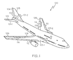
- FIG. 1 is a perspective view of an exemplary aircraft depicting primary and secondary flight control surfaces
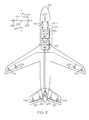
- FIG. 2 is a schematic depicting portions of an exemplary flight control surface actuation system according one embodiment of the present invention
- FIG. 3 is a functional block diagram of the flight control surface actuation system of FIG. 2, depicting certain portions thereof in slightly more detail;
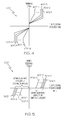
- FIG. 4 graphically depicts an exemplary motor feedback torque versus flight control stick position function that may be implemented by the flight control surface actuation system of FIG. 2;
- FIG. 5 depicts an exemplary added motor feedback torque versus flight control stick movement rate function that may be implemented by the flight control surface actuation system of FIG. 2;
- FIG. 6 depicts a graph of an exemplary aircraft flight envelope and stall boundaries for various flight control stick positions that may be implemented by the flight control surface actuation system of FIG. 2.
- the aircraft 100 includes first and second horizontal stabilizers 101-1 and 101-2, respectively, a vertical stabilizer 103, and first and second wings 105-1 and 105-2, respectively.
- An elevator 102 is disposed on each horizontal stabilizer 101-1, 101-2
- a rudder 104 is disposed on the vertical stabilizer 103
- an aileron 106 is disposed on each wing 105-1, 105-2.
- a plurality of flaps 108, slats 112, and spoilers 114 are disposed on each wing 105-1, 105-2.
- the elevators 102, the rudder 104, and the ailerons 106 are typically referred to as the primary flight control surfaces, and the flaps 108, the slats 112, and the spoilers 114 are typically referred to as the secondary flight control surfaces.
- the primary flight control surfaces 102-106 control aircraft movements about the aircraft pitch, yaw, and roll axes.
- the elevators 102 are used to control aircraft movement about the pitch axis
- the rudder 104 is used to control aircraft movement about the yaw axis
- the ailerons 106 control aircraft movement about the roll axis. It is noted, however, that aircraft movement about the yaw axis can also be achieved by varying the thrust levels from the engines on opposing sides of the aircraft 100. It will additionally be appreciated that the aircraft 100 could include horizontal stabilizers (not shown).
- the secondary control surfaces 108-114 influence the lift and drag of the aircraft 100.
- the flaps 108 and slats 112 may be moved from retracted positions to extended positions. In the extended position, the flaps 108 increase both lift and drag, and enable the aircraft 100 to descend more steeply for a given airspeed, and also enable the aircraft 100 get airborne over a shorter distance.
- the slats 112, in the extended position increase lift, and are typically used in conjunction with the flaps 108.
- the spoilers 114 reduce lift and when moved from retracted positions to extended positions, which is typically done during aircraft landing operations, may be used as air brakes to assist in slowing the aircraft 100.
- the flight control surfaces 102-114 are moved to commanded positions via a flight control surface actuation system 200, an exemplary embodiment of which is shown in FIG. 2.
- the flight control surface actuation system 200 includes one or more flight control units 202, a plurality of primary flight control surface actuators, which include elevator actuators 204, rudder actuators 206, and aileron actuators 208.
- the system 200 may be implemented with more than one flight control unit 202. However, for ease of description and illustration, only a single, multi-channel control unit 202 is depicted. It will additionally be appreciated that one or more functions of the control unit 202 could be implemented using a plurality of devices.
- the flight control surface actuation system 200 additionally includes a plurality of secondary control surface actuators, such as flap actuators, slat actuators, and spoiler actuators.
- secondary control surface actuators such as flap actuators, slat actuators, and spoiler actuators.
- the operation of the secondary flight control surfaces 108-114 and the associated actuators is not needed to fully describe and enable the present invention.
- the secondary flight control surfaces and actuators are not depicted in FIG. 2, nor are these devices further described.
- the flight control surface actuation system 200 may additionally be implemented using various numbers and types of primary flight control surface actuators 204-208.
- the number and type of primary flight control surface actuators 204-208 per primary flight control surface 102-106 may be varied. In the depicted embodiment, however, the system 200 is implemented such that two primary flight control surface actuators 204-208 are coupled to each primary flight control surface 102-106.
- each of the primary flight control surface actuators 204-208 are preferably a linear-type actuator, such as, for example, a ballscrew actuator. It will be appreciated that this number and type of primary flight control surface actuators 204-208 are merely exemplary of a particular embodiment, and that other numbers and types of actuators 204-208 could also be used.
- the flight control unit 202 is configured to receive aircraft flight control surface position commands from one or more input control mechanisms.
- the system 200 includes two user interfaces, a pilot user interface 210-1 and a co-pilot user interface 210-2, and one or more motor control circuits 212.
- the pilot 210-1 and co-pilot 210-2 user interfaces are both implemented as flight control sticks. It will be appreciated that in some embodiments, the system 200 could be implemented with more or less than this number of flight control sticks 210.
- each flight control unit 202 and each motor control circuit 212 could be integrated into a control circuit 215, as depicted in phantom in FIG. 2. Nonetheless, the motor control circuit 212, in response to position signals supplied from one or both flight control sticks 210, supplies flight control surface position signals to the flight control unit 202.
- the flight control unit 202 in response to the flight control surface position signals, supplies power to the appropriate primary flight control surface actuators 204-208, to move the appropriate primary flight control surfaces 102-106 to positions that will cause the aircraft 100 to implement the commanded maneuver. As depicted in phantom in FIG.
- the system 200 can be configured such that one or more signals from the user interfaces 210, such as the just-mentioned position signals, are supplied directly to the flight control unit 202, or are supplied to one or more aircraft data buses for communication to the flight control unit 202.
- FIG. 3 is also a functional block diagram of the flight control surface actuation system 200 depicting portions thereof in slightly more detail
- the flight control sticks 210 are each coupled to a gimbal assembly 302 (e.g., 302-1, 302-2), and are each configured to move, in response to input from either a pilot or a co-pilot, to a control position in a rotational direction.
- a gimbal assembly 302 e.g., 302-1, 302-2
- each flight control stick 210 is configured to rotate, from a null position 220 to a control position, about two perpendicular rotational axes, which in the depicted embodiment are a pitch axis 222 and a roll axis 224.
- the flight control stick 210 rotates about the pitch axis 222.
- the flight control stick 210 rotates about the roll axis 224.
- flight control stick 210 may be moved in a combined forward-port direction, a combined forward-starboard direction, a combined aft-port direction, or a combined aft-starboard direction, and back to or through the null position 220, to thereby implement a combined aircraft pitch and roll maneuver.
- the flight control sticks 210 are each configured to supply position signals 306 to either the motor control circuit 212, the flight control unit 202, or both, that are representative of its position.
- at least two position sensors 308 e.g., 308-1, 308-2 are coupled to each flight control stick 210, though it will be appreciated that more or less than this number of position sensors could be used. No matter the specific number, it will be appreciated that the position sensors 308 may be implemented using any one of numerous types of position sensors including, but not limited to, RVDTs and LVDTs.
- the motor control circuit 212 upon receipt of the position signals 306, supplies flight control surface position signals 312 to the flight control unit 202, which in turn supplies power to the appropriate primary flight control surface actuators 204-208, to move the appropriate primary flight control surfaces 102-106 to the appropriate positions, to thereby implement a desired maneuver.
- the flight control unit 202 may receive the position signals 306 directly from the positions sensors 308 and, in response, supply power to the appropriate primary flight control surface actuators 204-208, to move the appropriate primary flight control surfaces 102-106 to the appropriate positions.
- the flight control unit 202 may additionally include an auto-pilot, which may process the control surface commands before the commands are supplied to the primary flight control surface actuators 204-208. Also, the flight control surface position signals 312 supplied from the motor control circuit 212 to the flight control unit 202 may be based on an average of pilot and co-pilot stick positions 210.
- the motor control circuit 212 also receives one or more force feedback influence signals 314 from the flight control unit 202, and supplies motor drive signals 316 to one or two pilot motors 318-1, 318-2, or one or two co-pilot motor 318-3, 318-4, or various combinations thereof.
- the motors 318 which are each coupled to one of the flight control sticks 210 via associated gear sets 322 (e.g., 322-1, 322-2, 322-3, 322-4), are each operable, upon receipt of the motor drive signals 316, to supply a feedback force to the associated flight control stick 210.
- the motor drive signals 316 are variable in magnitude, based on the position of the flight control sticks 210, the slew rate of the flight control sticks 210, and various aircraft and control surface conditions, as represented by the one or more feedback influence signals 314.
- the motor drive signals 316 supplied to the pilot flight control stick 210-1 is also preferably variable in magnitude based on the position of the co-pilot flight control stick 210-2, and vice-versa.
- the flight control sticks 210 in response to the feedback force supplied from the associated motors 318, supplies haptic feedback to the pilot or co-pilot, as the case may be.
- current feedback signals 324 are supplied to the motor control circuit 212.
- current feedback and commutation signals 318 are supplied to the motor control circuit 212.
- the flight control unit 202 supplies one or more force feedback influence signals 314 to the motor control circuit 212.
- the feedback influence signals 31 vary in dependence upon various aircraft and control surface conditions.
- these signals include signals representative of control surface load rate limits, control surface slew rate limits, control surface no-load positions, and control surface stop positions. It will be appreciated that one or more of these parameters may vary with aircraft conditions.
- control surface load rate limits and control surface slew rate limits may vary with aircraft speed, angle-of-attack, etc.
- the flight control unit 202 receives a plurality of signals representative of aircraft conditions.
- these signals include primary flight control surface position signals 326, aircraft speed 328, aircraft altitude 332, and aircraft attitude 334.
- the flight control unit 202 may also receive a signal representative of aircraft operating envelope 336. It will be appreciated that one or more of these signals may be supplied from individual sensors that are dedicated to the system 200 or shared with other systems in the aircraft, or supplied via one or more data buses within the aircraft. No matter the specific source of each signal that is supplied to the flight control unit 202, the control unit 202 is further operable, in response to one or more of these signals 326-336, to supply the force feedback influence signals 314 to the motor control circuit 212.
- the force feedback influence signals 314, like the motor drive signals 316, are preferably variable in magnitude, based on the aircraft and control surface conditions, as represented by each of the aircraft condition signals 328-336, and the control surface position signals 326.
- the motor drive signals 316 supplied by the motor control circuit 212 vary in magnitude based, at least in part, on the position of the flight control sticks 210, the movement rate of the flight control sticks 210, and various aircraft and control surface conditions, as represented by the one or more feedback influence signals 314.
- the motor control circuit 212 is configured, upon receipt of the position signals 306, to determine the movement rate of the flight control sticks 210.
- the motor control circuit 212 is also configured, based on the force feedback influence signals 314, to determine aircraft control surface slew rate capacity, and aircraft control surface load rate capacity for the appropriate flight control surfaces.
- the motor drive signals 316 that the motor control circuit 212 supplies to the motors 318 is based, at least in part, on the determined control stick movement rate, the determined aircraft control surface slew rate capacity, and the determined aircraft control surface load rate capacity.
- FIG. 4 depicts an exemplary motor feedback torque versus flight control stick position function 400 that the motor control circuit 212 may implement
- FIG. 5 depicts an exemplary added motor feedback torque versus flight control stick movement rate that the motor control circuit 212 may implement.
- the torque versus position function 400 and the added torque versus rate function 500 are each depicted as a family of torques versus positions (402-1, 402-2, 402-3, ..., 402-N) and added torques versus rates (502-1, 502-2, 502-3, ..., 502-N), respectively, for various aircraft speeds, ranging from relatively low aircraft speeds 402-1, 502-1 to relatively high aircraft speeds 402-N, 502-N.
- the motor drive signals 316 that the motor control circuit 212 supplies to the motors 318 is such that the haptic feedback supplied by the motors 318, for a given control stick position, increases as aircraft speed increases.
- the motor drive signals 316 that the motor control circuit 212 supplies to the appropriate motors 318 will not result in increased haptic feedback to the flight control sticks 210.
- the motor control circuit 212 will supply motor drive signals to the appropriate motors 318 that cause the motors 318 to additional haptic feedback to the flight control stick 210.
- the control surface slew rates may vary with aircraft conditions, such as aircraft attitude and/or speed.
- FIG. 5 depicts, the added torque versus rate function 500 varies with aircraft speed.
- the motor drive signals 316 may vary based on a determination of an aerodynamic stall risk. More specifically, it is generally known that each aircraft has a predetermined operating envelope that may vary with various aircraft operating conditions, including the position of the flight control sticks 210. For example, and with reference now to FIG. 6, an allowable flight region 602 and an aerodynamic stall region 604 versus flight control stick positions (e.g., pitch and yaw) are graphically depicted. It will be appreciated that the flight envelope region 602 and aerodynamic stall region 604 will typically vary with aircraft and various other flight conditions.
- the motor control unit 212 and/or flight control unit 202 determines the aerodynamic stall risk of the aircraft.
- the motor drive signals 316 supplied to the motors 318 are then based on the determined aerodynamic stall risk. For example, if the flight control stick 210 is moved to a position that will cause, or will soon cause, an aerodynamic stall risk, the motor drive signals 316 will cause the motors 318 to supply an increased haptic feedback force to the flight control stick 210.
- the motor drive signals 316 that the motor control circuit 212 supplies to the motors 318 may also vary based on a mismatch in pilot and co-pilot stick positions, and on the control surface positions (e.g., a relatively high feedback force is supplied when control surface stops are reached).
- the pilot and co-pilot stick position deviation function can be overridden.
- the system 200 further includes a co-pilot override switch 338 and a pilot override switch 342.
- Each of these switches 338, 342 may be implemented as hardware switches or software switches, and are each movable between first and second positions.
- the motor control circuit 212 When the switches 338, 342 are in the first position, the motor control circuit 212 is responsive to the position signals 306 supplied from both the pilot and co-pilot flight control sticks 210, and the flight control surface position signals 312 supplied to the flight control unit 202 are preferably an average of the pilot and co-pilot flight control stick positions 210. Conversely, when the co-pilot 338 or pilot 342 override switch is in the second position, the motor control circuit 212 is responsive to only the position signal 306 supplied from the pilot or the co-pilot flight control stick, respectively.
- the system 200 described herein does not include a force sensor. Rather, by knowing the characteristics of the motors 318 and gear sets 322, the desired force feel can be determined and transmitted to the gripping point of the flight control sticks 210 without the feedback from a force sensor. If certain properties of the motors 318 and gear sets 322, such as friction or inertia, are undesirable, these properties can be cancelled or replaced by more desirable properties by the control laws and algorithms of the control unit 212. It is noted that often-times properties such as centering preload, mass, damping and hysteresis are specified by the end user. In addition, any undesirable effects introduced by accommodating these requirements, such as high-frequency chatter or oscillation, can be eliminated by proper filtering of the various control signals (motor position, speed and current). In this manner, the force sensor is not only eliminated, but is also improved upon.
Abstract
Description
- This application claims the benefit of
U.S. Provisional Application No. 60/854,764 filed October 26, 2006 - The present invention relates to aircraft flight control systems and, more particularly, to a pilot flight control stick haptic feedback system and method for an aircraft flight control system.
- Aircraft typically include a plurality of flight control surfaces that, when controllably positioned, guide the movement of the aircraft from one destination to another. The number and type of flight control surfaces included in an aircraft may vary, but typically include both primary flight control surfaces and secondary flight control surfaces. The primary flight control surfaces are those that are used to control aircraft movement in the pitch, yaw, and roll axes, and the secondary flight control surfaces are those that are used to influence the lift or drag (or both) of the aircraft. Although some aircraft may include additional control surfaces, the primary flight control surfaces typically include a pair of elevators, a rudder, and a pair of ailerons, and the secondary flight control surfaces typically include a plurality of flaps, slats, and spoilers.
- The positions of the aircraft flight control surfaces are typically controlled using a flight control surface actuation system. The flight control surface actuation system, in response to position commands that originate from either the flight crew or an aircraft autopilot, moves the aircraft flight control surfaces to the commanded positions. In most instances, this movement is effected via actuators that are coupled to the flight control surfaces.
- Typically, the position commands that originate from the flight crew are supplied via some type of input control mechanism. For example, many aircraft include two yoke and wheel type of mechanisms, one for the pilot and one for the co-pilot. Either mechanism can be used to generate desired flight control surface position commands. More recently, however, aircraft are being implemented with side stick type mechanisms. Most notably in aircraft that employ a fly-by-wire system. Similar to the traditional yoke and wheel mechanisms, it is common to include multiple side sticks in the cockpit, one for the pilot and one for the co-pilot. Most side sticks are implemented with some type of mechanism for providing force feedback (or "haptic feedback") to the user, be it the pilot or the co-pilot. In some implementations, one or more orthogonally arranged springs are used to provide force feedback. In other implementations, one or more electric motors are used to supply the force feedback.
- Although the above-described force feedback mechanisms are generally safe and reliable, each does suffer certain drawbacks. For example, the feedback mechanisms may not provide variable force feedback based on actual aircraft conditions. Moreover, the electric motor implementations are usually provided in double or triple redundant arrangements, which can increase overall system size, weight, and costs, and are usually implemented with force sensors, which also adds to system cost and complexity. Moreover, the feedback loop with force sensors and electric motors can be difficult to tune for acceptable haptic feedback because the motor is typically separated from the force sensor. This can lead to the addition of various other components and complexities.
- Hence, there is a need for a pilot side stick feedback mechanism that provides variable force feedback based on actual aircraft conditions and/or that can be implemented with relatively lightweight and/or relatively inexpensive components. The present invention addresses one or more of these needs.
- In one embodiment, and by way of example only, a pilot flight control stick haptic feedback system includes a pilot user interface, a position sensor, a pilot motor, and a control circuit. The pilot user interface is configured to receive user input and, upon receipt thereof, to move to a position at a movement rate. The position sensor is coupled to, and is configured to sense the position of, the pilot user interface. The position sensor is further configured to supply a pilot user interface position signal representative of the pilot user interface position. The pilot motor is coupled to the pilot user interface, and is further coupled to receive pilot motor feedback signals. The pilot motor is operable, upon receipt of the pilot motor feedback signals, to supply a feedback force to the pilot user interface at a magnitude based on the pilot motor feedback signals. The control circuit is coupled to receive at least the pilot user interface position signal and configured to determine the pilot user interface movement rate, aircraft control surface slew rate capacity, and aircraft control surface load rate capacity, and to supply the pilot motor feedback signals to the pilot motor based at least in part on the determined pilot user interface movement rate, the determined aircraft control surface slew rate capacity, and the determined aircraft control surface load rate capacity.
- In another exemplary embodiment, a pilot flight control stick haptic feedback system for an aircraft includes a pilot user interface, a position sensor, a pilot motor, and a control circuit. The pilot user interface is configured to receive user input and, upon receipt thereof, to move to a position. The position sensor is coupled to, and is configured to sense the position of, the pilot user interface, the position sensor is further configured to supply a pilot user interface position signal representative of the pilot user interface position. The pilot motor is coupled to the pilot user interface and to receive pilot motor feedback signals and is operable to supply a feedback force to the pilot user interface at a magnitude based on the pilot motor feedback signals. The control circuit is coupled to receive at least the pilot user interface position signal and is configured to determine an aerodynamic stall risk of the aircraft based on the pilot user interface position, and to supply the pilot motor feedback signals to the pilot motor based at least in part on the determined aerodynamic stall risk of the aircraft.
- In still another exemplary embodiment, a method of controlling haptic feedback to one or more aircraft flight control system user interfaces includes determining the movement rate of a pilot user interface, determining aircraft control surface slew rate capacity, and determining aircraft control surface load rate capacity. The haptic feedback is supplied to the pilot user interface at a magnitude that is based at least in part on the determined pilot user interface movement rate, the determined aircraft control surface slew rate capacity, and the determined aircraft control surface load rate capacity.
- In yet another exemplary embodiment, a method of controlling haptic feedback to one or more aircraft flight control system user interfaces includes determining pilot user interface position and an aerodynamic stall risk based on the determined pilot user interface position. The haptic feedback is supplied to the pilot user interface at a magnitude that is based at least in part on the determined aerodynamic stall risk.
- Other independent features and advantages of the preferred flight control stick haptic feedback system and method will become apparent from the following detailed description, taken in conjunction with the accompanying drawings which illustrate, by way of example, the principles of the invention.
- The present invention will hereinafter be described in conjunction with the following drawing figures, wherein like numerals denote like elements, and wherein:
- FIG. 1 is a perspective view of an exemplary aircraft depicting primary and secondary flight control surfaces;
- FIG. 2 is a schematic depicting portions of an exemplary flight control surface actuation system according one embodiment of the present invention;
- FIG. 3 is a functional block diagram of the flight control surface actuation system of FIG. 2, depicting certain portions thereof in slightly more detail;
- FIG. 4 graphically depicts an exemplary motor feedback torque versus flight control stick position function that may be implemented by the flight control surface actuation system of FIG. 2;
- FIG. 5 depicts an exemplary added motor feedback torque versus flight control stick movement rate function that may be implemented by the flight control surface actuation system of FIG. 2; and
- FIG. 6 depicts a graph of an exemplary aircraft flight envelope and stall boundaries for various flight control stick positions that may be implemented by the flight control surface actuation system of FIG. 2.
- The following detailed description is merely exemplary in nature and is not intended to limit the invention or the application and uses of the invention. Furthermore, there is no intention to be bound by any theory presented in the preceding background or the following detailed description.
- Turning first to FIG. 1, a perspective view of an exemplary aircraft is shown. In the illustrated embodiment, the
aircraft 100 includes first and second horizontal stabilizers 101-1 and 101-2, respectively, avertical stabilizer 103, and first and second wings 105-1 and 105-2, respectively. Anelevator 102 is disposed on each horizontal stabilizer 101-1, 101-2, arudder 104 is disposed on thevertical stabilizer 103, and anaileron 106 is disposed on each wing 105-1, 105-2. In addition, a plurality offlaps 108,slats 112, andspoilers 114 are disposed on each wing 105-1, 105-2. Theelevators 102, therudder 104, and theailerons 106 are typically referred to as the primary flight control surfaces, and theflaps 108, theslats 112, and thespoilers 114 are typically referred to as the secondary flight control surfaces. - The primary flight control surfaces 102-106 control aircraft movements about the aircraft pitch, yaw, and roll axes. Specifically, the
elevators 102 are used to control aircraft movement about the pitch axis, therudder 104 is used to control aircraft movement about the yaw axis, and theailerons 106 control aircraft movement about the roll axis. It is noted, however, that aircraft movement about the yaw axis can also be achieved by varying the thrust levels from the engines on opposing sides of theaircraft 100. It will additionally be appreciated that theaircraft 100 could include horizontal stabilizers (not shown). - The secondary control surfaces 108-114 influence the lift and drag of the
aircraft 100. For example, during aircraft take-off and landing operations, when increased lift is desirable, theflaps 108 andslats 112 may be moved from retracted positions to extended positions. In the extended position, theflaps 108 increase both lift and drag, and enable theaircraft 100 to descend more steeply for a given airspeed, and also enable theaircraft 100 get airborne over a shorter distance. Theslats 112, in the extended position, increase lift, and are typically used in conjunction with theflaps 108. Thespoilers 114, on the other hand, reduce lift and when moved from retracted positions to extended positions, which is typically done during aircraft landing operations, may be used as air brakes to assist in slowing theaircraft 100. - The flight control surfaces 102-114 are moved to commanded positions via a flight control
surface actuation system 200, an exemplary embodiment of which is shown in FIG. 2. In the depicted embodiment, the flight controlsurface actuation system 200 includes one or moreflight control units 202, a plurality of primary flight control surface actuators, which includeelevator actuators 204,rudder actuators 206, andaileron actuators 208. It will be appreciated that thesystem 200 may be implemented with more than oneflight control unit 202. However, for ease of description and illustration, only a single,multi-channel control unit 202 is depicted. It will additionally be appreciated that one or more functions of thecontrol unit 202 could be implemented using a plurality of devices. - Before proceeding further, it is noted that the flight control
surface actuation system 200 additionally includes a plurality of secondary control surface actuators, such as flap actuators, slat actuators, and spoiler actuators. However, the operation of the secondary flight control surfaces 108-114 and the associated actuators is not needed to fully describe and enable the present invention. Thus, for added clarity, ease of description, and ease of illustration, the secondary flight control surfaces and actuators are not depicted in FIG. 2, nor are these devices further described. - Returning now to the description, the flight control
surface actuation system 200 may additionally be implemented using various numbers and types of primary flight control surface actuators 204-208. In addition, the number and type of primary flight control surface actuators 204-208 per primary flight control surface 102-106 may be varied. In the depicted embodiment, however, thesystem 200 is implemented such that two primary flight control surface actuators 204-208 are coupled to each primary flight control surface 102-106. Moreover, each of the primary flight control surface actuators 204-208 are preferably a linear-type actuator, such as, for example, a ballscrew actuator. It will be appreciated that this number and type of primary flight control surface actuators 204-208 are merely exemplary of a particular embodiment, and that other numbers and types of actuators 204-208 could also be used. - No matter the specific number, configuration, and implementation of the
flight control units 202 and the primary flight control surface actuators 204-208, theflight control unit 202 is configured to receive aircraft flight control surface position commands from one or more input control mechanisms. In the depicted embodiment, thesystem 200 includes two user interfaces, a pilot user interface 210-1 and a co-pilot user interface 210-2, and one or moremotor control circuits 212. As will be described in more detail below, the pilot 210-1 and co-pilot 210-2 user interfaces are both implemented as flight control sticks. It will be appreciated that in some embodiments, thesystem 200 could be implemented with more or less than this number of flight control sticks 210. It will additionally be appreciated that the system could be implemented with more than onemotor control circuit 212, and that eachflight control unit 202 and eachmotor control circuit 212 could be integrated into acontrol circuit 215, as depicted in phantom in FIG. 2. Nonetheless, themotor control circuit 212, in response to position signals supplied from one or both flight control sticks 210, supplies flight control surface position signals to theflight control unit 202. Theflight control unit 202, in response to the flight control surface position signals, supplies power to the appropriate primary flight control surface actuators 204-208, to move the appropriate primary flight control surfaces 102-106 to positions that will cause theaircraft 100 to implement the commanded maneuver. As depicted in phantom in FIG. 2, in other embodiments thesystem 200 can be configured such that one or more signals from the user interfaces 210, such as the just-mentioned position signals, are supplied directly to theflight control unit 202, or are supplied to one or more aircraft data buses for communication to theflight control unit 202. - Turning now to FIG. 3, which is also a functional block diagram of the flight control
surface actuation system 200 depicting portions thereof in slightly more detail, the flight control sticks 210 are each coupled to a gimbal assembly 302 (e.g., 302-1, 302-2), and are each configured to move, in response to input from either a pilot or a co-pilot, to a control position in a rotational direction. Although the configuration of the flight control sticks 210 may vary, in the depicted embodiment, and with quick reference to FIG. 2, each flight control stick 210 is configured to rotate, from anull position 220 to a control position, about two perpendicular rotational axes, which in the depicted embodiment are apitch axis 222 and aroll axis 224. More specifically, if the pilot or co-pilot moves the flight control stick 210 in aforward direction 226 or anaft direction 228, to thereby control aircraft pitch, the flight control stick 210 rotates about thepitch axis 222. Similarly, if the pilot or co-pilot moves the flight control stick 210 in aport direction 232 or astarboard direction 234, to thereby control aircraft roll, the flight control stick 210 rotates about theroll axis 224. It will additionally be appreciated that the flight control stick 210 may be moved in a combined forward-port direction, a combined forward-starboard direction, a combined aft-port direction, or a combined aft-starboard direction, and back to or through thenull position 220, to thereby implement a combined aircraft pitch and roll maneuver. - Returning once again to FIG. 3, the flight control sticks 210, as noted above, are each configured to supply position signals 306 to either the
motor control circuit 212, theflight control unit 202, or both, that are representative of its position. To do so, at least two position sensors 308 (e.g., 308-1, 308-2) are coupled to each flight control stick 210, though it will be appreciated that more or less than this number of position sensors could be used. No matter the specific number, it will be appreciated that the position sensors 308 may be implemented using any one of numerous types of position sensors including, but not limited to, RVDTs and LVDTs. Themotor control circuit 212, at least in some embodiments, upon receipt of the position signals 306, supplies flight control surface position signals 312 to theflight control unit 202, which in turn supplies power to the appropriate primary flight control surface actuators 204-208, to move the appropriate primary flight control surfaces 102-106 to the appropriate positions, to thereby implement a desired maneuver. Alternatively, and as mentioned above and as depicted in phantom in FIG. 3, theflight control unit 202 may receive the position signals 306 directly from the positions sensors 308 and, in response, supply power to the appropriate primary flight control surface actuators 204-208, to move the appropriate primary flight control surfaces 102-106 to the appropriate positions. Theflight control unit 202 may additionally include an auto-pilot, which may process the control surface commands before the commands are supplied to the primary flight control surface actuators 204-208. Also, the flight control surface position signals 312 supplied from themotor control circuit 212 to theflight control unit 202 may be based on an average of pilot and co-pilot stick positions 210. - As FIG. 3 additionally depicts, the
motor control circuit 212 also receives one or more force feedback influence signals 314 from theflight control unit 202, and supplies motor drive signals 316 to one or two pilot motors 318-1, 318-2, or one or two co-pilot motor 318-3, 318-4, or various combinations thereof. The motors 318, which are each coupled to one of the flight control sticks 210 via associated gear sets 322 (e.g., 322-1, 322-2, 322-3, 322-4), are each operable, upon receipt of the motor drive signals 316, to supply a feedback force to the associated flight control stick 210. As will be described in more detail further below, the motor drive signals 316 are variable in magnitude, based on the position of the flight control sticks 210, the slew rate of the flight control sticks 210, and various aircraft and control surface conditions, as represented by the one or more feedback influence signals 314. The motor drive signals 316 supplied to the pilot flight control stick 210-1 is also preferably variable in magnitude based on the position of the co-pilot flight control stick 210-2, and vice-versa. The flight control sticks 210, in response to the feedback force supplied from the associated motors 318, supplies haptic feedback to the pilot or co-pilot, as the case may be. Preferably, current feedback signals 324 are supplied to themotor control circuit 212. Moreover, in a particular preferred embodiment, in which the motors 318 are implemented as permanent magnet brushless machine, current feedback and commutation signals 318 are supplied to themotor control circuit 212. - The
flight control unit 202, as noted above, supplies one or more force feedback influence signals 314 to themotor control circuit 212. The feedback influence signals 314, as was also noted above, vary in dependence upon various aircraft and control surface conditions. Although the number and types of force feedback influence signals 314 may vary, in the depicted embodiment these signals include signals representative of control surface load rate limits, control surface slew rate limits, control surface no-load positions, and control surface stop positions. It will be appreciated that one or more of these parameters may vary with aircraft conditions. For example, control surface load rate limits and control surface slew rate limits may vary with aircraft speed, angle-of-attack, etc. As such, and as FIG. 3 additionally depicts, theflight control unit 202 receives a plurality of signals representative of aircraft conditions. Although the specific number of signals, and the conditions of which each signal is representative of, may vary, in the depicted embodiment, these signals include primary flight control surface position signals 326,aircraft speed 328,aircraft altitude 332, andaircraft attitude 334. In addition, theflight control unit 202 may also receive a signal representative ofaircraft operating envelope 336. It will be appreciated that one or more of these signals may be supplied from individual sensors that are dedicated to thesystem 200 or shared with other systems in the aircraft, or supplied via one or more data buses within the aircraft. No matter the specific source of each signal that is supplied to theflight control unit 202, thecontrol unit 202 is further operable, in response to one or more of these signals 326-336, to supply the force feedback influence signals 314 to themotor control circuit 212. The force feedback influence signals 314, like the motor drive signals 316, are preferably variable in magnitude, based on the aircraft and control surface conditions, as represented by each of the aircraft condition signals 328-336, and the control surface position signals 326. - As was noted above, the motor drive signals 316 supplied by the
motor control circuit 212 vary in magnitude based, at least in part, on the position of the flight control sticks 210, the movement rate of the flight control sticks 210, and various aircraft and control surface conditions, as represented by the one or more feedback influence signals 314. In particular, it is noted that themotor control circuit 212 is configured, upon receipt of the position signals 306, to determine the movement rate of the flight control sticks 210. Themotor control circuit 212 is also configured, based on the force feedback influence signals 314, to determine aircraft control surface slew rate capacity, and aircraft control surface load rate capacity for the appropriate flight control surfaces. The motor drive signals 316 that themotor control circuit 212 supplies to the motors 318 is based, at least in part, on the determined control stick movement rate, the determined aircraft control surface slew rate capacity, and the determined aircraft control surface load rate capacity. - The above-described variation in haptic feedback may be more fully appreciated by referring to FIGS. 4-6. In particular, FIG. 4 depicts an exemplary motor feedback torque versus flight control
stick position function 400 that themotor control circuit 212 may implement, and FIG. 5 depicts an exemplary added motor feedback torque versus flight control stick movement rate that themotor control circuit 212 may implement. The torque versusposition function 400 and the added torque versusrate function 500 are each depicted as a family of torques versus positions (402-1, 402-2, 402-3, ..., 402-N) and added torques versus rates (502-1, 502-2, 502-3, ..., 502-N), respectively, for various aircraft speeds, ranging from relatively low aircraft speeds 402-1, 502-1 to relatively high aircraft speeds 402-N, 502-N. From the depicted torque versusposition function 400, it may be appreciated that the motor drive signals 316 that themotor control circuit 212 supplies to the motors 318 is such that the haptic feedback supplied by the motors 318, for a given control stick position, increases as aircraft speed increases. Moreover, from the depicted added torque versusrate function 500 it may be appreciated that if the movement rate of the flight control sticks 210 does not exceed the determined control surface slew rate capacity (or capacities), the motor drive signals 316 that themotor control circuit 212 supplies to the appropriate motors 318 will not result in increased haptic feedback to the flight control sticks 210. Conversely, if the movement rate of the flight control sticks 210 does exceed the determined control surface slew rate capacity (or capacities), themotor control circuit 212 will supply motor drive signals to the appropriate motors 318 that cause the motors 318 to additional haptic feedback to the flight control stick 210. The control surface slew rates, as may be appreciated, may vary with aircraft conditions, such as aircraft attitude and/or speed. Thus, as FIG. 5 depicts, the added torque versusrate function 500 varies with aircraft speed. - In addition to the above, the motor drive signals 316 may vary based on a determination of an aerodynamic stall risk. More specifically, it is generally known that each aircraft has a predetermined operating envelope that may vary with various aircraft operating conditions, including the position of the flight control sticks 210. For example, and with reference now to FIG. 6, an
allowable flight region 602 and anaerodynamic stall region 604 versus flight control stick positions (e.g., pitch and yaw) are graphically depicted. It will be appreciated that theflight envelope region 602 andaerodynamic stall region 604 will typically vary with aircraft and various other flight conditions. Nonetheless, themotor control unit 212 and/orflight control unit 202, based in part on the position of the flight control stick 210, determines the aerodynamic stall risk of the aircraft. The motor drive signals 316 supplied to the motors 318 are then based on the determined aerodynamic stall risk. For example, if the flight control stick 210 is moved to a position that will cause, or will soon cause, an aerodynamic stall risk, the motor drive signals 316 will cause the motors 318 to supply an increased haptic feedback force to the flight control stick 210. - The motor drive signals 316 that the
motor control circuit 212 supplies to the motors 318 may also vary based on a mismatch in pilot and co-pilot stick positions, and on the control surface positions (e.g., a relatively high feedback force is supplied when control surface stops are reached). In the depicted embodiment, the pilot and co-pilot stick position deviation function can be overridden. More specifically, and with reference once again to FIG. 3, it is seen that thesystem 200 further includes aco-pilot override switch 338 and apilot override switch 342. Each of theseswitches switches motor control circuit 212 is responsive to the position signals 306 supplied from both the pilot and co-pilot flight control sticks 210, and the flight control surface position signals 312 supplied to theflight control unit 202 are preferably an average of the pilot and co-pilot flight control stick positions 210. Conversely, when theco-pilot 338 orpilot 342 override switch is in the second position, themotor control circuit 212 is responsive to only the position signal 306 supplied from the pilot or the co-pilot flight control stick, respectively. - The
system 200 described herein does not include a force sensor. Rather, by knowing the characteristics of the motors 318 and gear sets 322, the desired force feel can be determined and transmitted to the gripping point of the flight control sticks 210 without the feedback from a force sensor. If certain properties of the motors 318 and gear sets 322, such as friction or inertia, are undesirable, these properties can be cancelled or replaced by more desirable properties by the control laws and algorithms of thecontrol unit 212. It is noted that often-times properties such as centering preload, mass, damping and hysteresis are specified by the end user. In addition, any undesirable effects introduced by accommodating these requirements, such as high-frequency chatter or oscillation, can be eliminated by proper filtering of the various control signals (motor position, speed and current). In this manner, the force sensor is not only eliminated, but is also improved upon. - While at least one exemplary embodiment has been presented in the foregoing detailed description of the invention, it should be appreciated that a vast number of variations exist. It should also be appreciated that the exemplary embodiment or exemplary embodiments are only examples, and are not intended to limit the scope, applicability, or configuration of the invention in any way. Rather, the foregoing detailed description will provide those skilled in the art with a convenient road map for implementing an exemplary embodiment of the invention. It being understood that various changes may be made in the function and arrangement of elements described in an exemplary embodiment without departing from the scope of the invention as set forth in the appended claims.
Claims (10)
- A pilot flight control stick haptic feedback system, comprising:a pilot user interface (210-1) configured to receive user input and, upon receipt thereof, to move to a position at a movement rate;a position sensor (308-1) coupled to, and configured to sense the position of, the pilot user interface (210-1), the position sensor (308-1) further configured to supply a pilot user interface position signal representative of the pilot user interface position;a pilot motor (318-1, 318-2) coupled to the pilot user interface (210-1), the pilot motor (318-1, 318-2) further coupled to receive pilot motor feedback signals and operable, upon receipt thereof, to supply a feedback force to the pilot user interface (210-1) at a magnitude based on the pilot motor feedback signals; anda control circuit (215) coupled to receive at least the pilot user interface position signal and configured to:(i) determine the pilot user interface movement rate, aircraft control surface slew rate capacity, and aircraft control surface load rate capacity, and(ii) supply the pilot motor feedback signals to the pilot motor (318-1, 318-2) based at least in part on the determined pilot user interface movement rate, the determined aircraft control surface slew rate capacity, and the determined aircraft control surface load rate capacity.
- The system of Claim 1, wherein:the control circuit (215) comprises a motor control circuit (212) and a flight control unit (202) coupled to the motor control circuit (212);the flight control unit (202) is configured to supply one or more force feedback influence signals (314) to the motor control circuit (212); andthe motor control circuit (212) is configured, in response to the one or more force feedback influence signals (314), to determine aircraft control surface slew rate capacity and aircraft control surface load rate capacity.
- The system of Claim 2, wherein the one or more force feedback influence signals (314) comprise one or more signals representative of control surface load rate limits, control surface slew rate limits, control surface no-load positions, or control surface stop positions.
- The system of Claim 1, wherein the control circuit (215) is further configured to supply the pilot motor feedback signals to the pilot motor (318-1, 318-2) based at least in part on flight control surface stop positions.
- The system of Claim 1, wherein the control circuit (215) is further configured to:determine an aerodynamic stall risk based on the pilot user interface position; andsupply the pilot motor feedback signals to the pilot motor (318-1, 318-2) based further in part on the determined aerodynamic stall risk.
- The system of Claim 1, further comprising:a co-pilot user interface (210-2) configured to receive user input and, upon receipt thereof, to move to a position at a movement rate;a co-pilot position sensor (308-2) coupled to, and configured to sense the position of, the co-pilot user interface (210-2), the co-pilot position sensor (308-2) further configured to supply a co-pilot user interface position signal representative of the co-pilot user interface position; anda co-pilot motor (318-3, 318-4) coupled to the co-pilot user interface (210-2), the co-pilot motor (318-3, 318-4) further coupled to receive co-pilot motor feedback signals and operable, upon receipt thereof, to supply a feedback force to the co-pilot user interface (210-2) at a magnitude based on the co-pilot motor feedback signals,wherein the control circuit (215) is further coupled to receive the co-pilot user interface position signal and is further configured to:(i) determine the pilot and co-pilot user interface movement rates, and(ii) supply the pilot and co-pilot motor feedback signals to the pilot and co-pilot motors (318-1, 318-2, 318-3, 318-4), respectively, based further in part on the co-pilot user interface movement rate.
- A pilot flight control stick haptic feedback system for an aircraft, the system comprising:a pilot user interface (210-1) configured to receive user input and, upon receipt thereof, to move to a position;a position sensor (308-1) coupled to, and configured to sense the position of, the pilot user interface (210-1), the position sensor (308-1) further configured to supply a pilot user interface position signal representative of the pilot user interface position;a pilot motor (318-1, 318-2) coupled to the pilot user interface (210-1), the pilot motor (318-1, 318-2) further coupled to receive pilot motor feedback signals and operable, upon receipt thereof, to supply a feedback force to the pilot user interface (210-1) at a magnitude based on the pilot motor feedback signals; anda control circuit (215) coupled to receive at least the pilot user interface position signal and configured to (i) determine an aerodynamic stall risk of the aircraft based on the pilot user interface position and (ii) supply the pilot motor feedback signals to the pilot motor (318-1, 318-2) based at least in part on the determined aerodynamic stall risk of the aircraft.
- A method of controlling haptic feedback to one or more aircraft flight control system user interfaces, the method comprising the steps of:determining movement rate of a pilot user interface (210-1);determining aircraft control surface slew rate capacity;determining aircraft control surface load rate capacity; andsupplying the haptic feedback to the pilot user interface (210-1) at a magnitude that is based at least in part on the determined pilot user interface movement rate, the determined aircraft control surface slew rate capacity, and the determined aircraft control surface load rate capacity.
- The method of Claim 8, further comprising:determining aircraft control surface slew rate capacity and aircraft control surface load rate capacity from one or more aircraft flight conditions.
- A method of controlling haptic feedback to one or more aircraft flight control system user interfaces, the method comprising the steps of:determining pilot user interface position;determining an aerodynamic stall risk based on the determined pilot user interface position; andsupplying the haptic feedback to the pilot user interface (210-1) at a magnitude that is based at least in part on the determined aerodynamic stall risk.
Applications Claiming Priority (2)
| Application Number | Priority Date | Filing Date | Title |
|---|---|---|---|
| US85476406P | 2006-10-26 | 2006-10-26 | |
| US11/739,479 US7658349B2 (en) | 2006-10-26 | 2007-04-24 | Pilot flight control stick haptic feedback system and method |
Publications (2)
| Publication Number | Publication Date |
|---|---|
| EP1918196A1 true EP1918196A1 (en) | 2008-05-07 |
| EP1918196B1 EP1918196B1 (en) | 2009-10-07 |
Family
ID=38963117
Family Applications (1)
| Application Number | Title | Priority Date | Filing Date |
|---|---|---|---|
| EP07119237A Expired - Fee Related EP1918196B1 (en) | 2006-10-26 | 2007-10-24 | Pilot flight control stick haptic feedback system and method |
Country Status (3)
| Country | Link |
|---|---|
| US (1) | US7658349B2 (en) |
| EP (1) | EP1918196B1 (en) |
| DE (1) | DE602007002683D1 (en) |
Cited By (12)
| Publication number | Priority date | Publication date | Assignee | Title |
|---|---|---|---|---|
| EP2279941A1 (en) | 2009-07-28 | 2011-02-02 | Eurocopter | Variable damping of haptic feedback for kinematic linkage to change the flight attitude of an aircraft |
| FR2952448A1 (en) * | 2009-11-06 | 2011-05-13 | Ratier Figeac Soc | DEVICE FOR ELECTRONIC CONTROL OF A MULTIFUNCTIONAL MICROCONTROLLER DRIVER, STEERING DEVICE AND AIRCRAFT |
| FR2952447A1 (en) * | 2009-11-06 | 2011-05-13 | Ratier Figeac Soc | ELECTRONIC CONTROL DEVICE FOR OPERATING A CRUISE MONITORING DRIVER, STEERING DEVICE AND AIRCRAFT |
| CN102452478A (en) * | 2010-10-22 | 2012-05-16 | 伍德沃德Mpc股份有限公司 | Line replaceable fly-by-wire control columns with push-pull interconnect rods |
| US8196857B2 (en) | 2009-06-04 | 2012-06-12 | Eurocopter | Variable ratio crank for a manual flight control linkage of a rotary wing aircraft |
| US8729848B2 (en) | 2010-12-22 | 2014-05-20 | Woodward Mpc Inc. | Fail-passive variable gradient control stick drive system |
| US8814103B2 (en) | 2010-07-28 | 2014-08-26 | Woodward Mpc, Inc. | Position control system for cross coupled operation of fly-by-wire control columns |
| US9051045B2 (en) | 2010-07-28 | 2015-06-09 | Woodward Mpc, Inc. | Indirect drive active control column |
| WO2015128162A1 (en) * | 2014-02-28 | 2015-09-03 | Sagem Defense Securite | A flight control device for an aircraft |
| US9405312B2 (en) | 2010-07-28 | 2016-08-02 | Woodward Mpc, Inc. | Active control column with manually activated reversion to passive control column |
| EP2960746B1 (en) | 2014-06-25 | 2017-12-27 | Iveco Magirus Ag | Control system and method for controlling the movement of an aerial apparatus |
| WO2020234011A1 (en) * | 2019-05-20 | 2020-11-26 | Florian Maier | Method and device for controlling motors in the film and broadcasting industry |
Families Citing this family (20)
| Publication number | Priority date | Publication date | Assignee | Title |
|---|---|---|---|---|
| US8725321B2 (en) * | 2006-05-17 | 2014-05-13 | Textron Innovations Inc. | Flight control system |
| US9340278B2 (en) | 2006-05-17 | 2016-05-17 | Textron Innovations, Inc. | Flight control system |
| CA2683132C (en) * | 2007-04-05 | 2013-10-29 | Bombardier Inc. | Multi-axis serially redundant, single channel, multi-path fly-by-wire flight control system |
| US8078340B2 (en) * | 2007-11-12 | 2011-12-13 | Honeywell International Inc. | Active user interface haptic feedback and linking control system using either force or position data |
| US9156546B2 (en) * | 2008-03-11 | 2015-10-13 | The Boeing Company | Active-inceptor tactile-cueing hands-off rate-limit |
| FR2934065B1 (en) * | 2008-07-17 | 2010-08-27 | Airbus France | DEVICE FOR DETERMINING THE POSITION OF A GAS LEVER IN AN AIRCRAFT |
| DE102010019236B4 (en) * | 2010-05-03 | 2014-07-17 | Deutsches Zentrum für Luft- und Raumfahrt e.V. | Contact recognition |
| CN103782502B (en) * | 2011-07-26 | 2017-11-17 | 莫戈公司 | motor clamping system |
| WO2014025772A2 (en) * | 2012-08-06 | 2014-02-13 | University Of Miami | Systems and methods for responsive neurorehabilitation |
| FR3012112B1 (en) * | 2013-10-22 | 2017-04-21 | Ratier Figeac Soc | METHOD FOR MONITORING THE OPERATION OF AN AIRCRAFT DRIVING DEVICE AND AIRCRAFT DRIVING DEVICE SO MONITORED |
| US20150274279A1 (en) * | 2014-03-31 | 2015-10-01 | Wyatt Logan Sinko | Method and system for control input detection |
| US10118688B2 (en) | 2015-08-18 | 2018-11-06 | Woodward, Inc. | Inherently balanced control stick |
| WO2018039988A1 (en) * | 2016-08-31 | 2018-03-08 | SZ DJI Technology Co., Ltd. | Methods and systems for brushless motor control |
| KR102622032B1 (en) * | 2016-10-21 | 2024-01-10 | 삼성전자주식회사 | Unmanned flying vehicle and flying control method thereof |
| US10074245B2 (en) * | 2017-01-10 | 2018-09-11 | Woodward, Inc. | Force feel using a brushless DC motor |
| US10737769B1 (en) * | 2017-02-21 | 2020-08-11 | Jack Hohner | Tactile feedback aircraft control grip |
| EP3505440B1 (en) | 2017-12-28 | 2022-03-09 | Goodrich Actuation Systems SAS | Horizontal stabilizer trim actuator assembly |
| US11009892B2 (en) | 2019-03-19 | 2021-05-18 | Honeywell International Inc. | Active human-machine user interface feedback system with spherical motor |
| US11235885B2 (en) * | 2019-12-20 | 2022-02-01 | Pratt & Whitney Canada Corp. | Method and system for determining a throttle position of an aircraft |
| US11854738B2 (en) * | 2021-12-02 | 2023-12-26 | Cirrus Logic Inc. | Slew control for variable load pulse-width modulation driver and load sensing |
Citations (5)
| Publication number | Priority date | Publication date | Assignee | Title |
|---|---|---|---|---|
| EP0384806A1 (en) * | 1989-02-20 | 1990-08-29 | AEROSPATIALE Société Nationale Industrielle | Control device with a pivoting handle, especially for aircraft, and system incorporating two of such devices |
| US5489830A (en) * | 1994-09-09 | 1996-02-06 | Mcdonnell Douglas Corporation | Control system with loadfeel and backdrive |
| US20030094539A1 (en) * | 2000-05-16 | 2003-05-22 | Schaeffer Joseph M. | Power lever tactile cueing system |
| WO2003081554A1 (en) * | 2002-03-21 | 2003-10-02 | Bell Helicopter Textron Inc. | Method and apparatus for tactile cueing of aircraft controls |
| WO2005044622A2 (en) * | 2003-10-28 | 2005-05-19 | United States Of America As Represented By The Administrator Of The National Aeronautics And Space Administration | Method and apparatus for loss of control inhibitor systems |
Family Cites Families (19)
| Publication number | Priority date | Publication date | Assignee | Title |
|---|---|---|---|---|
| US2983469A (en) * | 1956-08-31 | 1961-05-09 | Gen Electric | Maneuver limiter for aircraft |
| US3015458A (en) * | 1956-10-01 | 1962-01-02 | Gen Electric | Stall and high speed bufffeting limiter for aircraft |
| US3094300A (en) * | 1960-06-23 | 1963-06-18 | Sperry Rand Corp | Flight path control system |
| US3578267A (en) * | 1968-11-21 | 1971-05-11 | Lear Siegler Inc | Control system with multiple function capability |
| US3960348A (en) * | 1975-08-04 | 1976-06-01 | United Technologies Corporation | Aerodynamic surface control feel augmentation system |
| US4150803A (en) * | 1977-10-05 | 1979-04-24 | Fernandez Carlos P | Two axes controller |
| US4477043A (en) * | 1982-12-15 | 1984-10-16 | The United States Of America As Represented By The Secretary Of The Air Force | Biodynamic resistant control stick |
| DE3416969A1 (en) * | 1984-05-08 | 1985-11-14 | Messerschmitt-Bölkow-Blohm GmbH, 8012 Ottobrunn | METHOD AND DEVICE FOR STABILIZING THE TAX FORCE IN A TURNING PLANE |
| US4659313A (en) * | 1985-11-01 | 1987-04-21 | New Flite Inc. | Control yoke apparatus for computerized aircraft simulation |
| US4795296A (en) * | 1986-11-17 | 1989-01-03 | California Institute Of Technology | Hand-held robot end effector controller having movement and force control |
| US5213282A (en) * | 1991-08-28 | 1993-05-25 | United Technologies Corporation | Maneuver feel system for a rotary wing aircraft |
| US5291113A (en) * | 1992-10-06 | 1994-03-01 | Honeywell Inc. | Servo coupled hand controllers |
| FR2708112B1 (en) * | 1993-07-22 | 1995-09-01 | Ratier Figeac Soc | Control device with a control handle, in particular a servo-controlled mini-handle for aircraft. |
| FR2728537A1 (en) * | 1994-12-21 | 1996-06-28 | Eurocopter France | DEVICE FOR ACTUATING A CONTROL MEMBER FOR AN AIRCRAFT, IN PARTICULAR A HELICOPTER, WITH ELECTRIC FLIGHT CONTROLS |
| JPH0924898A (en) * | 1995-07-12 | 1997-01-28 | Teijin Seiki Co Ltd | Steering device for small aircraft |
| US6459228B1 (en) * | 2001-03-22 | 2002-10-01 | Mpc Products Corporation | Dual input servo coupled control sticks |
| US6648269B2 (en) * | 2001-12-10 | 2003-11-18 | Sikorsky Aircraft Corporation | Trim augmentation system for a rotary wing aircraft |
| US20030183728A1 (en) * | 2002-03-29 | 2003-10-02 | The Boeing Company | Aircraft control surface controller and associated method |
| US6644600B1 (en) * | 2002-04-25 | 2003-11-11 | Rockwell Collins, Inc. | Method and system for providing manipulation restraining forces for a stick controller on an aircraft |
-
2007
- 2007-04-24 US US11/739,479 patent/US7658349B2/en not_active Expired - Fee Related
- 2007-10-24 EP EP07119237A patent/EP1918196B1/en not_active Expired - Fee Related
- 2007-10-24 DE DE602007002683T patent/DE602007002683D1/en active Active
Patent Citations (5)
| Publication number | Priority date | Publication date | Assignee | Title |
|---|---|---|---|---|
| EP0384806A1 (en) * | 1989-02-20 | 1990-08-29 | AEROSPATIALE Société Nationale Industrielle | Control device with a pivoting handle, especially for aircraft, and system incorporating two of such devices |
| US5489830A (en) * | 1994-09-09 | 1996-02-06 | Mcdonnell Douglas Corporation | Control system with loadfeel and backdrive |
| US20030094539A1 (en) * | 2000-05-16 | 2003-05-22 | Schaeffer Joseph M. | Power lever tactile cueing system |
| WO2003081554A1 (en) * | 2002-03-21 | 2003-10-02 | Bell Helicopter Textron Inc. | Method and apparatus for tactile cueing of aircraft controls |
| WO2005044622A2 (en) * | 2003-10-28 | 2005-05-19 | United States Of America As Represented By The Administrator Of The National Aeronautics And Space Administration | Method and apparatus for loss of control inhibitor systems |
Cited By (20)
| Publication number | Priority date | Publication date | Assignee | Title |
|---|---|---|---|---|
| US8196857B2 (en) | 2009-06-04 | 2012-06-12 | Eurocopter | Variable ratio crank for a manual flight control linkage of a rotary wing aircraft |
| EP2279941A1 (en) | 2009-07-28 | 2011-02-02 | Eurocopter | Variable damping of haptic feedback for kinematic linkage to change the flight attitude of an aircraft |
| FR2952448A1 (en) * | 2009-11-06 | 2011-05-13 | Ratier Figeac Soc | DEVICE FOR ELECTRONIC CONTROL OF A MULTIFUNCTIONAL MICROCONTROLLER DRIVER, STEERING DEVICE AND AIRCRAFT |
| FR2952447A1 (en) * | 2009-11-06 | 2011-05-13 | Ratier Figeac Soc | ELECTRONIC CONTROL DEVICE FOR OPERATING A CRUISE MONITORING DRIVER, STEERING DEVICE AND AIRCRAFT |
| US8659257B2 (en) | 2009-11-06 | 2014-02-25 | Ratier Figeac | Electronic operational control device for a piloting member with cross-monitoring, piloting device and aircraft |
| US8814103B2 (en) | 2010-07-28 | 2014-08-26 | Woodward Mpc, Inc. | Position control system for cross coupled operation of fly-by-wire control columns |
| US9405312B2 (en) | 2010-07-28 | 2016-08-02 | Woodward Mpc, Inc. | Active control column with manually activated reversion to passive control column |
| US9051045B2 (en) | 2010-07-28 | 2015-06-09 | Woodward Mpc, Inc. | Indirect drive active control column |
| US8469317B2 (en) | 2010-10-22 | 2013-06-25 | Woodward Mpc, Inc. | Line replaceable, fly-by-wire control columns with push-pull interconnect rods |
| JP2012091779A (en) * | 2010-10-22 | 2012-05-17 | Woodward Mpc Inc | Line replaceable, fly-by-wire control column with push-pull interconnect rod |
| CN102452478A (en) * | 2010-10-22 | 2012-05-16 | 伍德沃德Mpc股份有限公司 | Line replaceable fly-by-wire control columns with push-pull interconnect rods |
| GB2484830B (en) * | 2010-10-22 | 2013-03-27 | Woodward Mpc Inc | Line replaceable, fly-by-wire control columns with push-pull interconnect rods |
| CN102452478B (en) * | 2010-10-22 | 2016-03-23 | 伍德沃德Mpc股份有限公司 | The removable Flight By Wire of circuit with push-pull type interconnected rod controls post |
| US8729848B2 (en) | 2010-12-22 | 2014-05-20 | Woodward Mpc Inc. | Fail-passive variable gradient control stick drive system |
| WO2015128162A1 (en) * | 2014-02-28 | 2015-09-03 | Sagem Defense Securite | A flight control device for an aircraft |
| CN106061837A (en) * | 2014-02-28 | 2016-10-26 | 赛峰电子与防务公司 | A flight control device for an aircraft |
| US9738374B2 (en) | 2014-02-28 | 2017-08-22 | Safran Electronics & Defense | Flight control device for an aircraft |
| EP2960746B1 (en) | 2014-06-25 | 2017-12-27 | Iveco Magirus Ag | Control system and method for controlling the movement of an aerial apparatus |
| WO2020234011A1 (en) * | 2019-05-20 | 2020-11-26 | Florian Maier | Method and device for controlling motors in the film and broadcasting industry |
| US11899343B2 (en) | 2019-05-20 | 2024-02-13 | Florian Maier | Method and device for controlling motors in the film and broadcast industry |
Also Published As
| Publication number | Publication date |
|---|---|
| US20080099629A1 (en) | 2008-05-01 |
| EP1918196B1 (en) | 2009-10-07 |
| DE602007002683D1 (en) | 2009-11-19 |
| US7658349B2 (en) | 2010-02-09 |
Similar Documents
| Publication | Publication Date | Title |
|---|---|---|
| EP1918196B1 (en) | Pilot flight control stick haptic feedback system and method | |
| EP2076432B1 (en) | Cogless motor driven active user interface haptic feedback system | |
| EP1908685B1 (en) | Motor balanced active user interface assembly | |
| EP2058227B1 (en) | Active user interface haptic feedback and linking control system using either force or position data | |
| US8240617B2 (en) | Variable damping of haptic feedback for a flight-attitude changing linkage of an aircraft | |
| EP2134598B1 (en) | Vertical speed and flight path command algorithm for displacement collective utilizing tactile cueing and tactile feedback | |
| US20070235594A1 (en) | Pilot flight control stick feedback system | |
| US8080966B2 (en) | Motor control architecture for simultaneously controlling multiple motors | |
| US7770842B2 (en) | Aircraft flight control surface actuation system communication architecture | |
| US8002220B2 (en) | Rate limited active pilot inceptor system and method | |
| KR101323836B1 (en) | Emergency piloting by means of a series actuator for a manual flight control system in an aircraft | |
| EP1942388A1 (en) | Active pilot flight control stick system with passive electromagnetic feedback | |
| EP2583896B1 (en) | Methods and Systems for Providing Constant-Feel, Multi-Axis Tactile Cues | |
| EP1977970A2 (en) | User interface passive haptic feedback system | |
| EP2112063A2 (en) | Active pilot inceptor with self warm-up | |
| US11667375B2 (en) | System and method of VTOL vehicle flight control inceptors | |
| EP2078997A2 (en) | Human-machine interface with variable null breakout force | |
| EP1781538B1 (en) | Aircraft flight control surface actuation system communication architecture | |
| EP3478576A1 (en) | Split-aileron control | |
| EP3193230B1 (en) | Pilot activated trim for fly-by-wire aircraft |
Legal Events
| Date | Code | Title | Description |
|---|---|---|---|
| PUAI | Public reference made under article 153(3) epc to a published international application that has entered the european phase |
Free format text: ORIGINAL CODE: 0009012 |
|
| 17P | Request for examination filed |
Effective date: 20071024 |
|
| AK | Designated contracting states |
Kind code of ref document: A1 Designated state(s): AT BE BG CH CY CZ DE DK EE ES FI FR GB GR HU IE IS IT LI LT LU LV MC MT NL PL PT RO SE SI SK TR |
|
| AX | Request for extension of the european patent |
Extension state: AL BA HR MK RS |
|
| 17Q | First examination report despatched |
Effective date: 20080625 |
|
| AKX | Designation fees paid |
Designated state(s): DE FR GB |
|
| GRAP | Despatch of communication of intention to grant a patent |
Free format text: ORIGINAL CODE: EPIDOSNIGR1 |
|
| GRAS | Grant fee paid |
Free format text: ORIGINAL CODE: EPIDOSNIGR3 |
|
| GRAA | (expected) grant |
Free format text: ORIGINAL CODE: 0009210 |
|
| AK | Designated contracting states |
Kind code of ref document: B1 Designated state(s): DE FR GB |
|
| REG | Reference to a national code |
Ref country code: GB Ref legal event code: FG4D |
|
| REF | Corresponds to: |
Ref document number: 602007002683 Country of ref document: DE Date of ref document: 20091119 Kind code of ref document: P |
|
| PLBE | No opposition filed within time limit |
Free format text: ORIGINAL CODE: 0009261 |
|
| STAA | Information on the status of an ep patent application or granted ep patent |
Free format text: STATUS: NO OPPOSITION FILED WITHIN TIME LIMIT |
|
| 26N | No opposition filed |
Effective date: 20100708 |
|
| REG | Reference to a national code |
Ref country code: FR Ref legal event code: PLFP Year of fee payment: 9 |
|
| PGFP | Annual fee paid to national office [announced via postgrant information from national office to epo] |
Ref country code: GB Payment date: 20150924 Year of fee payment: 9 |
|
| PGFP | Annual fee paid to national office [announced via postgrant information from national office to epo] |
Ref country code: FR Payment date: 20150924 Year of fee payment: 9 |
|
| PGFP | Annual fee paid to national office [announced via postgrant information from national office to epo] |
Ref country code: DE Payment date: 20151030 Year of fee payment: 9 |
|
| REG | Reference to a national code |
Ref country code: DE Ref legal event code: R119 Ref document number: 602007002683 Country of ref document: DE |
|
| GBPC | Gb: european patent ceased through non-payment of renewal fee |
Effective date: 20161024 |
|
| REG | Reference to a national code |
Ref country code: FR Ref legal event code: ST Effective date: 20170630 |
|
| PG25 | Lapsed in a contracting state [announced via postgrant information from national office to epo] |
Ref country code: GB Free format text: LAPSE BECAUSE OF NON-PAYMENT OF DUE FEES Effective date: 20161024 Ref country code: FR Free format text: LAPSE BECAUSE OF NON-PAYMENT OF DUE FEES Effective date: 20161102 Ref country code: DE Free format text: LAPSE BECAUSE OF NON-PAYMENT OF DUE FEES Effective date: 20170503 |
|
| P01 | Opt-out of the competence of the unified patent court (upc) registered |
Effective date: 20230525 |