EP1916524A1 - Rotatable test element - Google Patents
Rotatable test element Download PDFInfo
- Publication number
- EP1916524A1 EP1916524A1 EP06020219A EP06020219A EP1916524A1 EP 1916524 A1 EP1916524 A1 EP 1916524A1 EP 06020219 A EP06020219 A EP 06020219A EP 06020219 A EP06020219 A EP 06020219A EP 1916524 A1 EP1916524 A1 EP 1916524A1
- Authority
- EP
- European Patent Office
- Prior art keywords
- sample
- test element
- axis
- zone
- porous
- Prior art date
- Legal status (The legal status is an assumption and is not a legal conclusion. Google has not performed a legal analysis and makes no representation as to the accuracy of the status listed.)
- Ceased
Links
Images


Classifications
-
- B—PERFORMING OPERATIONS; TRANSPORTING
- B01—PHYSICAL OR CHEMICAL PROCESSES OR APPARATUS IN GENERAL
- B01L—CHEMICAL OR PHYSICAL LABORATORY APPARATUS FOR GENERAL USE
- B01L3/00—Containers or dishes for laboratory use, e.g. laboratory glassware; Droppers
- B01L3/50—Containers for the purpose of retaining a material to be analysed, e.g. test tubes
- B01L3/502—Containers for the purpose of retaining a material to be analysed, e.g. test tubes with fluid transport, e.g. in multi-compartment structures
- B01L3/5027—Containers for the purpose of retaining a material to be analysed, e.g. test tubes with fluid transport, e.g. in multi-compartment structures by integrated microfluidic structures, i.e. dimensions of channels and chambers are such that surface tension forces are important, e.g. lab-on-a-chip
- B01L3/502753—Containers for the purpose of retaining a material to be analysed, e.g. test tubes with fluid transport, e.g. in multi-compartment structures by integrated microfluidic structures, i.e. dimensions of channels and chambers are such that surface tension forces are important, e.g. lab-on-a-chip characterised by bulk separation arrangements on lab-on-a-chip devices, e.g. for filtration or centrifugation
-
- B—PERFORMING OPERATIONS; TRANSPORTING
- B01—PHYSICAL OR CHEMICAL PROCESSES OR APPARATUS IN GENERAL
- B01L—CHEMICAL OR PHYSICAL LABORATORY APPARATUS FOR GENERAL USE
- B01L3/00—Containers or dishes for laboratory use, e.g. laboratory glassware; Droppers
- B01L3/50—Containers for the purpose of retaining a material to be analysed, e.g. test tubes
- B01L3/502—Containers for the purpose of retaining a material to be analysed, e.g. test tubes with fluid transport, e.g. in multi-compartment structures
- B01L3/5023—Containers for the purpose of retaining a material to be analysed, e.g. test tubes with fluid transport, e.g. in multi-compartment structures with a sample being transported to, and subsequently stored in an absorbent for analysis
-
- B—PERFORMING OPERATIONS; TRANSPORTING
- B01—PHYSICAL OR CHEMICAL PROCESSES OR APPARATUS IN GENERAL
- B01L—CHEMICAL OR PHYSICAL LABORATORY APPARATUS FOR GENERAL USE
- B01L3/00—Containers or dishes for laboratory use, e.g. laboratory glassware; Droppers
- B01L3/50—Containers for the purpose of retaining a material to be analysed, e.g. test tubes
- B01L3/502—Containers for the purpose of retaining a material to be analysed, e.g. test tubes with fluid transport, e.g. in multi-compartment structures
- B01L3/5027—Containers for the purpose of retaining a material to be analysed, e.g. test tubes with fluid transport, e.g. in multi-compartment structures by integrated microfluidic structures, i.e. dimensions of channels and chambers are such that surface tension forces are important, e.g. lab-on-a-chip
- B01L3/50273—Containers for the purpose of retaining a material to be analysed, e.g. test tubes with fluid transport, e.g. in multi-compartment structures by integrated microfluidic structures, i.e. dimensions of channels and chambers are such that surface tension forces are important, e.g. lab-on-a-chip characterised by the means or forces applied to move the fluids
-
- B—PERFORMING OPERATIONS; TRANSPORTING
- B01—PHYSICAL OR CHEMICAL PROCESSES OR APPARATUS IN GENERAL
- B01L—CHEMICAL OR PHYSICAL LABORATORY APPARATUS FOR GENERAL USE
- B01L3/00—Containers or dishes for laboratory use, e.g. laboratory glassware; Droppers
- B01L3/50—Containers for the purpose of retaining a material to be analysed, e.g. test tubes
- B01L3/502—Containers for the purpose of retaining a material to be analysed, e.g. test tubes with fluid transport, e.g. in multi-compartment structures
- B01L3/5027—Containers for the purpose of retaining a material to be analysed, e.g. test tubes with fluid transport, e.g. in multi-compartment structures by integrated microfluidic structures, i.e. dimensions of channels and chambers are such that surface tension forces are important, e.g. lab-on-a-chip
- B01L3/502738—Containers for the purpose of retaining a material to be analysed, e.g. test tubes with fluid transport, e.g. in multi-compartment structures by integrated microfluidic structures, i.e. dimensions of channels and chambers are such that surface tension forces are important, e.g. lab-on-a-chip characterised by integrated valves
-
- B—PERFORMING OPERATIONS; TRANSPORTING
- B01—PHYSICAL OR CHEMICAL PROCESSES OR APPARATUS IN GENERAL
- B01L—CHEMICAL OR PHYSICAL LABORATORY APPARATUS FOR GENERAL USE
- B01L2200/00—Solutions for specific problems relating to chemical or physical laboratory apparatus
- B01L2200/06—Fluid handling related problems
- B01L2200/0605—Metering of fluids
-
- B—PERFORMING OPERATIONS; TRANSPORTING
- B01—PHYSICAL OR CHEMICAL PROCESSES OR APPARATUS IN GENERAL
- B01L—CHEMICAL OR PHYSICAL LABORATORY APPARATUS FOR GENERAL USE
- B01L2300/00—Additional constructional details
- B01L2300/06—Auxiliary integrated devices, integrated components
- B01L2300/0627—Sensor or part of a sensor is integrated
- B01L2300/0663—Whole sensors
-
- B—PERFORMING OPERATIONS; TRANSPORTING
- B01—PHYSICAL OR CHEMICAL PROCESSES OR APPARATUS IN GENERAL
- B01L—CHEMICAL OR PHYSICAL LABORATORY APPARATUS FOR GENERAL USE
- B01L2300/00—Additional constructional details
- B01L2300/06—Auxiliary integrated devices, integrated components
- B01L2300/0681—Filter
-
- B—PERFORMING OPERATIONS; TRANSPORTING
- B01—PHYSICAL OR CHEMICAL PROCESSES OR APPARATUS IN GENERAL
- B01L—CHEMICAL OR PHYSICAL LABORATORY APPARATUS FOR GENERAL USE
- B01L2300/00—Additional constructional details
- B01L2300/06—Auxiliary integrated devices, integrated components
- B01L2300/069—Absorbents; Gels to retain a fluid
-
- B—PERFORMING OPERATIONS; TRANSPORTING
- B01—PHYSICAL OR CHEMICAL PROCESSES OR APPARATUS IN GENERAL
- B01L—CHEMICAL OR PHYSICAL LABORATORY APPARATUS FOR GENERAL USE
- B01L2300/00—Additional constructional details
- B01L2300/08—Geometry, shape and general structure
- B01L2300/0803—Disc shape
- B01L2300/0806—Standardised forms, e.g. compact disc [CD] format
-
- B—PERFORMING OPERATIONS; TRANSPORTING
- B01—PHYSICAL OR CHEMICAL PROCESSES OR APPARATUS IN GENERAL
- B01L—CHEMICAL OR PHYSICAL LABORATORY APPARATUS FOR GENERAL USE
- B01L2300/00—Additional constructional details
- B01L2300/08—Geometry, shape and general structure
- B01L2300/0861—Configuration of multiple channels and/or chambers in a single devices
-
- B—PERFORMING OPERATIONS; TRANSPORTING
- B01—PHYSICAL OR CHEMICAL PROCESSES OR APPARATUS IN GENERAL
- B01L—CHEMICAL OR PHYSICAL LABORATORY APPARATUS FOR GENERAL USE
- B01L2400/00—Moving or stopping fluids
- B01L2400/04—Moving fluids with specific forces or mechanical means
- B01L2400/0403—Moving fluids with specific forces or mechanical means specific forces
- B01L2400/0406—Moving fluids with specific forces or mechanical means specific forces capillary forces
-
- B—PERFORMING OPERATIONS; TRANSPORTING
- B01—PHYSICAL OR CHEMICAL PROCESSES OR APPARATUS IN GENERAL
- B01L—CHEMICAL OR PHYSICAL LABORATORY APPARATUS FOR GENERAL USE
- B01L2400/00—Moving or stopping fluids
- B01L2400/04—Moving fluids with specific forces or mechanical means
- B01L2400/0403—Moving fluids with specific forces or mechanical means specific forces
- B01L2400/0409—Moving fluids with specific forces or mechanical means specific forces centrifugal forces
-
- B—PERFORMING OPERATIONS; TRANSPORTING
- B01—PHYSICAL OR CHEMICAL PROCESSES OR APPARATUS IN GENERAL
- B01L—CHEMICAL OR PHYSICAL LABORATORY APPARATUS FOR GENERAL USE
- B01L2400/00—Moving or stopping fluids
- B01L2400/06—Valves, specific forms thereof
- B01L2400/0688—Valves, specific forms thereof surface tension valves, capillary stop, capillary break
-
- B—PERFORMING OPERATIONS; TRANSPORTING
- B01—PHYSICAL OR CHEMICAL PROCESSES OR APPARATUS IN GENERAL
- B01L—CHEMICAL OR PHYSICAL LABORATORY APPARATUS FOR GENERAL USE
- B01L2400/00—Moving or stopping fluids
- B01L2400/08—Regulating or influencing the flow resistance
- B01L2400/082—Active control of flow resistance, e.g. flow controllers
-
- Y—GENERAL TAGGING OF NEW TECHNOLOGICAL DEVELOPMENTS; GENERAL TAGGING OF CROSS-SECTIONAL TECHNOLOGIES SPANNING OVER SEVERAL SECTIONS OF THE IPC; TECHNICAL SUBJECTS COVERED BY FORMER USPC CROSS-REFERENCE ART COLLECTIONS [XRACs] AND DIGESTS
- Y10—TECHNICAL SUBJECTS COVERED BY FORMER USPC
- Y10T—TECHNICAL SUBJECTS COVERED BY FORMER US CLASSIFICATION
- Y10T436/00—Chemistry: analytical and immunological testing
- Y10T436/11—Automated chemical analysis
- Y10T436/110833—Utilizing a moving indicator strip or tape
-
- Y—GENERAL TAGGING OF NEW TECHNOLOGICAL DEVELOPMENTS; GENERAL TAGGING OF CROSS-SECTIONAL TECHNOLOGIES SPANNING OVER SEVERAL SECTIONS OF THE IPC; TECHNICAL SUBJECTS COVERED BY FORMER USPC CROSS-REFERENCE ART COLLECTIONS [XRACs] AND DIGESTS
- Y10—TECHNICAL SUBJECTS COVERED BY FORMER USPC
- Y10T—TECHNICAL SUBJECTS COVERED BY FORMER US CLASSIFICATION
- Y10T436/00—Chemistry: analytical and immunological testing
- Y10T436/11—Automated chemical analysis
- Y10T436/111666—Utilizing a centrifuge or compartmented rotor
Definitions
- the invention relates to a test element, which is substantially disc-shaped and flat and about a central axis which is perpendicular to the disc-shaped test element plane, rotatable, comprising a sample application port for discharging a liquid sample, a porous, absorbent matrix and a sample channel, of the Sample introduction opening to the porous, absorbent matrix is sufficient. Furthermore, the invention relates to a method for determining an analyte with the aid of the test element.
- test carriers eg. B. Test strips offered. Prominent examples of these are test strips for the determination of the blood glucose value or test strips for urinalysis.
- test carriers usually integrate several functions (eg the storage of reagents in dried form or, albeit less frequently, in solution, the separation of undesired sample constituents, in particular of red blood cells from whole blood, in immunoassays, the so-called Free separation, the dosing of sample volumes, the transport of sample liquid from outside a device into a device, the control of the sequence of individual reaction steps, etc.).
- the function of the sample transport is often accomplished by means of absorbent materials (eg papers or fleeces), by means of capillary channels or by application of external driving forces (such as pressure, suction) or by means of centrifugal force.
- Disc-shaped test carriers so-called LabDiscs or optical BioDiscs, continue the idea of controlled sample transport by means of centrifugal force (centrifugal force).
- Such Disc-shaped, CompactDisc-like test carriers allow miniaturization through the use of microfluidic structures and at the same time the parallelization of processes by repeated application of identical structures for the parallel processing of similar analyzes from a sample or identical analyzes from different samples.
- optical BioDiscs the integration of optically stored digital data for the identification of the test carriers or the control of the analysis systems on the optical BioDiscs is possible.
- BioDiscs In addition to the miniaturization and parallelization of analyzes and the integration of digital data on optical discs, BioDiscs generally have the advantage that they can be manufactured using established manufacturing methods and measured using established evaluation technology. In the chemical and biochemical components of such optical BioDiscs usually a recourse to known chemical and biochemical components is possible.
- a disadvantage of the optical LabDiscs or Biodiscs based purely on centrifugal and capillary forces is that the immobilization of reagents is difficult and the accuracy of detection suffers. Especially in detection systems based on specific binding reactions, such.
- As immunoassays lacks compared to conventional test strip systems, the volume component, especially in the so-called. Bound-Free separation.
- BioDiscs with channels and channel-like structures for liquid transport on the one hand and voluminous absorbent materials in these structures (at least partially) on the other.
- WO 2005/001429 (Phan et al. ) describes optical bio-discs which have membrane pieces as reagent carriers in parts of the channel system. The reagents are dissolved by a liquid supplied to the disc, resulting in buffered reagent solutions, which are then contacted with the sample.
- optical bio-disks which contain absorbent membranes or papers for moving a sample liquid, separating particulate sample components, carrying reagents, and analyzing the sample.
- the sample is first applied to a blood separation membrane near the outer edge of the bio-disk and migrates radially therethrough to a reagent paper located closer to the center of the bio-disk. Thereafter, the sample is again moved radially outward, ie away from the center of the bio-disk, and flows through a so-called Analysis membrane.
- the outward movement takes place via chromatography, which is supported by rotation of the bio-disk and the centrifugal force acting thereon on the sample.
- US 2002/0076354 A1 discloses bio-optical discs having, in addition to a channel system for the transport of a liquid sample, a so-called “capture layer".
- the latter can for example consist of nitrocellulose.
- the "interception layer” is traversed by means of centrifugal forces during rotation of the disk.
- a disadvantage of the concepts of the prior art is that just for specific binding assays, such.
- immunoassays targeted control of the reaction and residence times of the sample liquid after receiving the reagents and after flowing into the porous, absorbent matrix is not possible.
- the object of the invention is to eliminate the disadvantages of the prior art.
- the invention relates to a test element according to claim 1 or 14, a measuring system according to claim 18, the use thereof according to claim 19, as well as a method according to claim 15.
- Advantageous embodiments and preferred embodiments of the invention are the subject of the dependent claims.
- test element is essentially disc-shaped and planar. It is rotatable about a central axis which is perpendicular to the disk-shaped test element plane.
- the test element is a circular disc, comparable to a compact disc.
- the invention is not limited to this form of the disc, but can readily be found in non-symmetrical or non-circular discs use.
- the test element first contains a sample introduction opening into which a liquid sample can be pipetted or introduced in another way.
- the Sample loading aperture can either be close to the axis (ie near the center of the disc) or far away from the axis (ie near the edge of the disc).
- the test element contains at least one channel, which can transfer the liquid sample from the off-axis position into an axis-near position by means of capillary forces.
- the sample application opening can open directly into a sample channel.
- the sample introduction opening can first open into a reservoir located behind it, into which the sample flows before it continues to flow into the sample channel.
- a hydrophilization of the surfaces of the fluidic structures may be necessary and / or the use of structures that promote the formation of capillary forces.
- test element contains a porous, absorbent matrix which accommodates at least part of the liquid sample.
- the matrix has an off-axis first end and an off-axis second end.
- the test element also has a sample channel that extends from the sample introduction port to the off-axis first end of the porous absorbent matrix. At least once, the sample channel passes through an area close to the axis, which is closer to the central axis than the first end of the porous matrix, which is remote from the axis.
- the porous, absorbent matrix has an axis-proximate second end.
- the off-axis first end of the porous, absorbent matrix is in contact with the sample channel, in which the sample can be moved by capillary forces and / or centrifugal forces and / or other external forces, such as overpressure or underpressure.
- the liquid sample - possibly after taking up reagents and / or dilution media and / or precluding reactions - reaches the off-axis first end of the porous, absorbent matrix, it is taken up in the matrix and transported through the suction forces.
- the porous, absorbent matrix is a paper, membrane or web.
- the porous absorbent matrix typically contains one or more zones of immobilized reagents.
- specific binding agents such as specific binding partners, such as antigens, antibodies, (poly) haptens, streptavidin, polystreptavidin, and the like, are immobilized in the absorbent matrix. They serve to selectively capture from the sample flowing through the absorbent matrix the analyte or analyte-derived and related species.
- an antibody to the analyte may be immobilized in the porous, bibulous matrix which will then capture the analyte (in this case, an antigen or hapten) from the sample and also immobilize it in the bibulous matrix.
- the analyte can be made detectable by further reactions, for example by further contacting with a labeled bindable partner, for example by a label which can be visually, optically or fluorescently detected.
- the porous, absorbent matrix with the second end close to the axis adjoins another absorbent material, so that this liquid can absorb from the matrix.
- the matrix and other material overlap slightly for this purpose.
- the other material serves on the one hand to support the suction of the matrix, on the other hand as a receiving zone for liquid, which has already passed through the matrix.
- the further material may consist of the same or different materials, such as the matrix.
- the matrix may be a membrane and the other absorbent material may be a nonwoven or a paper. Other combinations are of course possible as well.
- the test element according to the invention is characterized in a preferred embodiment in that the sample channel contains zones of different dimensions and / or for different functions.
- the sample channel may contain a zone containing soluble or suspendible reagents in the sample. These can be dissolved or suspended in the liquid sample when it flows in or through it and can react with the analyte in the sample or with other sample components.
- the different zones in the sample channel may also differ in that there are zones with capillary activity and those without.
- zones of high hydrophilicity and low hydrophilicity may be included.
- the individual zones can virtually seamlessly pass into each other or through certain barriers, such as valves, in particular non-closing valves, such as geometric valves or hydrophobes be separated from each other.
- the reagents in the sample channel are preferably in dried or lyophilized form. However, it is also conceivable, although less preferred, for reagents to be present in liquid form in the test element according to the invention.
- the reagents can be introduced into the test element in a manner known per se.
- the test element preferably contains at least two layers, a bottom layer into which the fluidic structures are introduced, and a cover layer, which as a rule contains no further structures apart from the inlet openings for liquids and the vent openings.
- the introduction of reagents during the preparation of the test device is usually carried out before the upper part of the test element (cover layer) is applied to the lower part (bottom layer). At this time, the fluidic structures are open in the lower part, so that a dosage of the reagents in liquid or dried form is readily possible.
- the introduction of the reagents can be done for example by printing or dispensing.
- the reagents into the test element by placing them in the test element impregnated in absorbent materials such as papers, nonwovens or membranes. After placing the reagents and inserting the absorbent materials, such as the porous, absorbent matrix (membrane) and optionally other absorbent materials (non-woven waste etc.) upper and lower part of the test element are connected to each other, for example, clipped, welded, glued and such more.
- absorbent materials such as papers, nonwovens or membranes.
- the bottom layer in addition to the fluidic structures also has the inlet openings for liquids and the vent openings.
- the cover layer may be formed completely without openings, with the possible exception of a central recess for receiving a drive unit.
- the upper part simply consist of a plastic film which is glued or welded to the lower part.
- the sample channel contains a zone for separating particulate matter from the liquid sample.
- this zone serves to separate the cellular sample components. From blood can be so by separating in particular the red blood cells (erythrocytes) almost colorless plasma or serum which is usually better suited for subsequent visual or optical detection methods than the strongly colored blood.
- the separation of cellular sample components by centrifugation, d. H. by fast rotation of the test element after filling with liquid sample contains suitably dimensioned and geometrically designed channels and / or chambers for this purpose.
- the test element for the separation of cellular blood components contains an erythrocyte collection zone (erythrocyte chamber or erythrocyte trap) and a serum or plasma collection zone (serum or plasma chamber).
- valves In control the flow of the sample liquid in the test element, it may contain valves, in particular so-called non-closing or geometric valves or hydrophobic barriers, especially in the sample channel.
- valves or hydrophobic barriers can be used to ensure that a targeted temporal and spatial control of the sample flow through the sample channel and the individual zone of the test element is possible.
- the sample channel may have a sample metering zone, which allows a precise measurement of the - initially in excess abandoned - sample.
- the sample metering zone extends from the sample application opening via a corresponding piece of a sample channel to a valve in the fluidic structure, in particular a geometric valve or a hydrophobic barrier.
- the sample application opening can initially receive an excess of sample material.
- the sample either driven by capillary forces or by centrifugation, flows from the sample application zone into the channel structure and fills it up to the valve. Excess sample initially remains in the sample application zone.
- a sample excess chamber adjacent to the sample application zone and branching off from the sample channel is filled, for example by capillary forces or by centrifuging the test element. It must be ensured that the sample volume to be measured is initially not transported across the valve by suitably selecting the valve. As soon as excess sample is trapped in the appropriate transfer chamber, there is a well-defined sample volume between the valve of the sample channel on one side and the entrance to the sample overflow chamber on the other side. By applying external forces, in particular by starting another centrifugation, this defined sample volume now extends beyond the valve emotional. All fluidic areas that lie after the valve and come into contact with the sample are now filled with a precisely defined sample volume.
- the sample channel may also have an inflow for other liquids except the sample liquid.
- a second channel open, the z. B. can be filled with a washing or reagent liquid.
- the inventive system of measuring device and test element is used to determine an analyte in a liquid sample.
- the measuring device contains at least one drive for the rotation of the test element and an evaluation optics for evaluating the visual or optical signal of the test element.
- the optics of the measuring device can be used for fluorescence measurement with spatially resolved detection.
- d. H. planar evaluation optics is typically used to illuminate the detection area of the test element and possibly the excitation of optically detectable markers an LED or a laser.
- the detection of the optical signal is by CMOS or CCD (typically 640 x 480 pixels).
- the beam path is direct or folded (eg via mirrors or prisms).
- the illumination or excitation is typically effected by means of an illumination line which illuminates the detection area of the test element, preferably perpendicular to the detection and control lines.
- the detection can be done here via a diode array.
- the rotational movement of the device can be utilized for the illumination and evaluation of the second dimension in order to scan with the diode array over the area of the test element to be evaluated.
- a DC motor with encoder or a stepper motor can be used as drive for rotating and positioning of the test element.
- the temperature of the test element in the device is made indirectly, for example by heating or cooling the plate on which rests the disc-shaped test element in the device.
- the measurement of the temperature is preferably carried out without contact.
- the method according to the invention serves to detect an analyte in a liquid sample.
- the sample is first introduced into the sample application opening of the test element according to the invention.
- the test element is rotated about its central axis: The sample is transported from the sample application opening to the off-axis end of the porous, absorbent matrix.
- the rotation of the test element then becomes so far slows or stops that the sample or a material obtained from the sample as it flows through the test element from the off-axis to the near-axis end of the porous, absorbent matrix is sucked.
- the analyte is finally visually or optically detected in the porous, absorbent matrix or a downstream zone.
- the detection can be carried out according to the principle of the sandwich assay or in the form of a competitive assay.
- the further liquid may in particular be a buffer, preferably a washing buffer, or a reagent liquid.
- the porous, absorbent matrix transports the liquid from an off-axis end to an off-axis end, i. H. from the periphery of the disk-shaped test element in the direction of the axis of rotation.
- the centrifugal force which can also be used to move the liquids, counteracts this direction of transport exactly.
- Targeted control of the rotation of the test element therefore makes it possible to slow down or stop the flow of the sample liquid in the porous, absorbent matrix, so that targeted and defined reaction conditions can be maintained.
- the use of the porous absorbent matrix which serves essentially as a scavenger matrix for bound-free separation in immunoassays, allows efficient capture of sample components during the immunoassay.
- FIG. 1 shows a schematic representation of a plan view of a preferred embodiment of the test element according to the invention. For the sake of clarity, only the layer of the test element which contains the fluidic structures is shown. The embodiment shown here contains only one opening for introducing sample and / or washing liquid. The separation of interfering sample components is done in this embodiment) after the sample has been contacted with reagents.
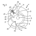
- FIG. 2 schematically shows a further preferred embodiment of the test element according to the invention. Again, only the structure has been shown, which has the fluidic elements of the test element. In this embodiment of the test element there are two separate sample and wash buffer application ports. A separation of the cellular sample components takes place here already before the sample is brought into contact with reagents.
- FIG. 3 shows a variant of the embodiment according to FIG. 1 in a schematic representation. Again, the separation of cellular sample components, after which the sample was brought into contact with reagents. However, the structure according to FIG. 3 has a separate feed for washing liquid.
- FIG. 4 shows a further preferred embodiment of the test element according to the invention in a schematic view analogous to FIG. 2.
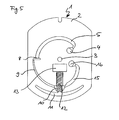
- FIG. 5 represents a slight further development of the test element according to FIG. 3.
- FIG. 5 contains a different geometric arrangement of the waste nonwoven and another type of valve at the end of the sample metering section.
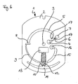
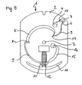
- FIG. 6 schematically shows a plan view of a further development of the test element according to FIG. 5.
- the embodiment according to FIG. 6 contains a fluidic structure for receiving a sample excess.
- FIG. 7 is a schematic representation of a further variant of the test element according to FIG. 3. Functionally, the fluidic structures are essentially analogous to those of FIG. 3. However, they are geometrically differently aligned and designed.
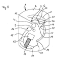
- FIG. 8 schematically shows a further preferred embodiment of the test element according to the invention.
- the structures in FIG. 8 essentially correspond to the functions which are already known by the test element according to FIG.
- FIG. 9 schematically shows a plan view of an alternative to the test element according to FIG. 6.
- the embodiment according to FIG. 9 contains an off-axis sample application opening, which initially brings the sample nearer to the center of the test element via a capillary, that is to say in FIG an off-axis area.
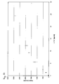
- FIG. 10 shows the typical curve for troponin T measurements in whole blood samples (concentration of troponin T in ng / ml plotted against the signal strength (counts)). The samples were supplemented with recombinant troponin T to the respective concentration. The data belong to Example 2 and were obtained with the aid of test elements according to FIG. 6 / Example 1.
- FIGS. 1 to 9 show different preferred embodiments of the test element (1) according to the invention.
- each of the substrate (2) containing the fluidic structures and the central recess (drive hole 3) is shown.
- the disk-shaped test element (1) according to the invention also generally comprises a cover layer, which in the figures provides clarity is not shown half.
- the cover layer can also carry structures, but as a rule it will have no structures other than the openings for the samples and / or further liquids to be dispensed onto the test element.
- the cover layer can also be designed completely without openings, for example in the form of a film, which is connected to the substrate and terminates the structures located therein.
- FIGS. 1 to 9 show fluidic structures that perform largely similar functions, although they differ in detail from embodiment to embodiment.
- the basic structure and the basic function will therefore be explained in more detail here with reference to the embodiment according to FIG.
- the embodiments according to FIGS. 2 to 9 will subsequently be explained in more detail merely with reference to the specific differences in order to avoid unnecessary repetitions.
- FIG. 1 shows a first preferred embodiment of the disk-shaped test element (1) according to the invention.
- the test element (1) contains a substrate (2) containing the fluidic and microfluidic and chromatographic structures.
- the substrate (2) is covered by a corresponding counterpart (cover layer) (not shown), which contains sample application and ventilation openings which lead to the structures in the substrate (2). correspond.
- Both the cover layer and the substrate (2) have a central recess (3) which, in cooperation with a corresponding drive unit in a measuring device, makes it possible to rotate the disk-shaped test element (1).
- the test element accordinging to one of FIGS.
- Sample liquid in particular whole blood, is supplied to the test element (1) via the sample application opening (4). Driven by capillary forces and / or centrifugal forces, the sample liquid fills the sample dosing zone (5).
- the sample metering zone (5) can also contain the dried reagents. It is limited by the Kapillarstopps (6 and 8), which may be formed for example as a hydrophobic barrier or as a geometric / non-closing valve.
- the limitation of the sample dosing zone (5) by the capillary stops (6, 8) ensures that a defined sample volume is taken up and passed on into the fluidic zones which lie downstream of the sample dosing zone (5).
- channel (9) is used to start the separation of red blood cells and other cellular sample components.
- the reagents contained in the sample dosing zone (5) are already dissolved in the sample when the sample enters the channel (9).
- the entry of the sample in channel (9) via the capillary stop (8) leads to a mixing of the reagents in the sample.
- the reagent-sample mixture is directed into the fluidic structures (10) (serum / plasma collection zone) and (11) (erythrocyte collection zone). Due to the centrifugal forces acting on the reagent-sample mixture, plasma or serum is separated from red blood cells. The red blood cells collect in the process Erythrocyte collection zone (11) while the plasma remains substantially in the collection zone (10).
- the membranes or nonwovens for separating particulate sample components use (for example, glass fiber webs or asymmetrically porous plastic membranes for separating red blood cells from whole blood) generally referred to as blood-separating membranes or nonwovens), the sample volume can be exploited much more effectively with the test elements according to the invention, as there are virtually no dead volumes (eg, volume of fiber interstices or pores) from which the sample can not be withdrawn.
- these prior art blood separation membranes and webs tend in part to undesirably adsorb sample components (e.g., proteins) or destroy (lysate) cells, which is also not observed with the test elements of the present invention.
- the reagent-plasma mixture (which has formed in the presence of the analyte in the case of an immunoassay, for example sandwich complexes of analyte and antibody conjugates) by the suction of the porous-absorbent matrix (12) incorporated into and passed through them.
- the immobilized binding partners contained in the membrane (12) capture the analyte-containing complexes in the detection zone and bound unbound labeled conjugate in the control zone.
- the nonwoven (13) adjoining the porous, absorbent matrix supports the movement of the sample through the membrane (12).
- the fleece (13) also serves to receive the sample after flowing through the membrane (12).
- wash buffer is pipetted into the sample application opening (4).
- the washing buffer flows through the corresponding fluidic structures of the test element (1) and, in particular, washes the membrane (12), where the bound analyte complexes are now located, thus removing excess reagent residues.
- the washing step may be repeated one or more times so as to improve the signal-to-background ratio. This allows an optimization of the detection limit for the analyte and an increase of the dynamic measuring range.
- the sample channel in which the liquid sample in the test element (1) is transported from the sample application opening (4) to the first end of the membrane (12) remote from the axis comprises In this case, the sample dosing zone (5), the capillary stop (8), the channel (9), the serum / plasma collection zone (10) and the erythrocyte chamber (11). In other embodiments, the sample channel may consist of more or fewer individual zones / chambers.
- FIGS. 3, 5, 6, 7 and 9 show essentially analogous embodiments to FIG. 1.
- FIG. 3 differs from FIG. 1 in that on the one hand, no container for excess sample (7) adjoins the sample application opening (4) and at the end of the Probenendosierabitess (5) no capillary stop is present (ie here a metered sample application is required) and on the other hand, that a separate addition port (16) for other liquids, such as.
- washing buffer, and an associated channel (15) are present, which can transport the buffer to the membrane (12).
- the transport of the buffer to the membrane (12) can be based on capillary forces or centrifugal forces.
- the embodiment according to FIG. 5 is largely identical to the embodiment according to FIG. 3.
- the two embodiments differ only in the shape of the waste fleece (13) and in that the test element according to FIG. 5 has a capillary stop (8) at the end of the sample-metering section (FIG. 5).
- FIG. 6 is again essentially identical to the embodiment according to FIG. 5 and differs therefrom by the additional presence of a container for sample excess (7) in the region between the sample metering opening (4) and the sample metering zone (5).
- a container for sample excess (7) in the region between the sample metering opening (4) and the sample metering zone (5).
- no metered application of the sample is required (analogous to FIG. 1).
- the embodiment of the test element (1) according to the invention according to FIG. 7 substantially corresponds to the test element (1) of FIG. 6. Both embodiments have the same fluidic structures and functions. Only the arrangement and geometric design is different.
- the embodiment according to FIG. 7 has additional ventilation openings (17), which are necessary due to the different dimensioning of the fluidic structures in comparison to FIG. 6 in order to allow filling of the structures with samples or washing liquid.
- Channel (9) is designed here as a thin capillary, which is filled only during rotation of the test element (ie overcoming the capillary stop (8) is possible only by means of centrifugal force).
- the test element (1) according to FIG. 7 it is possible with the test element (1) according to FIG. 7 to remove recovered plasma from the erythrocyte collection zone 11; This is done by the decanter unit 18, which finally discharges into the serum / plasma collection zone 10.
- test element (1) according to the invention according to FIG. 9 essentially corresponds to the test element (1) of FIG. 6. Both embodiments have the same fluidic structures and functions. Only the arrangement and geometric design is different.
- the embodiment according to FIG. 9 basically has a further outward, that is, away from the axis, sample application opening (4). This can be advantageous if the test element (1) for filling with sample is already introduced in a measuring device. In this case, the user can be made more easily accessible to the sample application opening (4) than is possible with test elements according to Figures 1 to 8, where the sample application opening (4) is arranged close to the axis (ie remote from the outer edge of the test element).
- the separation of the cellular sample components from the sample liquid takes place before the sample comes into contact with reagents.
- This has the advantage that the use of whole blood or plasma or serum as a sample material does not lead to different measurement results, since always initially plasma or serum comes into contact with the reagents and the dissolution / incubation / reaction behavior should be practically the same .
- the liquid sample is first applied to the test element (1) via the sample application opening (4). By capillary forces and / or centrifugal forces, the sample is then transported from the sample application opening (4) in the channel structures.
- the sample is transferred into a sample metering section (5) after it has been introduced into the sample application opening (4), and then a serum / plasma separation from the whole blood is effected by rotation.
- the unwanted cellular sample constituents essentially erythrocytes, accumulate in the erythrocyte trap (11), while serum or plasma accumulate in the zone (10).
- the serum is removed from the zone (10) via a capillary and transported further into the channel structure (9), where dried reagents are accommodated and are dissolved when the sample flows in.
- the sample-reagent mixture of channel structure (9) can overcome the capillary stop (14) and thus reach the membrane (12) via the channel (15).
- the sample-reagent mixture is transported via the membrane (12) into the waste nonwoven (13).
- FIG. 2 and FIG. 4 differ from one another in that a container for sample excess (7) is provided in FIG. 2, while the embodiment according to Figure 4 does not provide such a function.
- a metered application of the sample is expedient here.
- FIG. 8 shows a variant of the embodiments according to FIGS. 2 and 4.
- the sample is transferred by centrifugation into an erythrocyte separation structure (10, 11).
- the area denoted by (10) serves as a serum / plasma collection zone (10) from which serum or plasma freed from cells is passed on via a capillary channel (21) after centrifuging.
- Chamber (20) serves as a collecting reservoir for excess serum or plasma, which after complete filling of the sample dosing section (5) possibly flows from the serum / plasma collection zone (10). All other functions and structures are analogous to FIGS. 1 to 7.
- the hydrophilic or hydrophobic properties of the surfaces of the test element (1) By deliberately designing the hydrophilic or hydrophobic properties of the surfaces of the test element (1), it can be achieved that the sample liquid and / or washing liquids are moved either only with the aid of rotation and the resulting centrifugal forces or by a combination of centrifugal forces and capillary forces. The latter requires at least partially hydrophilized surfaces in the fluidic structures of the test element (1).
- test elements according to the invention according to FIGS. 1, 2, 6, 7, 8 and 9 have an automatic functionality which allows a relatively accurate measurement of a sample aliquot from a sample which has been applied in excess to the test element allowed (so-called "metering system").
- This metering system is a further subject of the present invention. It essentially comprises the elements 4, 5, 6, and 7 of the illustrated test elements (1).
- Sample liquid in particular whole blood, is supplied to the test element (1) via the sample application opening (4). Driven by capillary forces and / or centrifugal forces, the sample liquid fills the sample dosing zone (5).
- the sample metering zone (5) can also contain the dried reagents.
- the Kapillarstopps (6 and 8) which may be formed for example as a hydrophobic barrier or as geometric / non-closing valves.
- the limitation of the sample dosing zone (5) by the capillary stops (6, 8) ensures that a defined sample volume is taken up and passed on into the fluidic zones which lie downstream of the sample dosing zone (5).
- a possible excess sample from the sample application opening (4) and the sample dosing (5) is transferred to the sample surplus container (7) while the measured amount of sample is transferred from the sample dosing zone (5) to the channel (9).
- sample liquid can be applied in excess to a test element.
- the measurement of a relatively accurate sample aliquot, which is then further processed in the test element also takes place here by the interaction of a metering chamber and an overflow chamber, these two zones - unlike the present invention - by a narrow, but at least during filling always liquid exchange enabling contact.
- Sample liquid is here directly separated during filling of the test element in a part which is passed through a wide channel in the "metering chamber", and a part which flows through a narrow channel in the "overflow chamber”.
- the test element is set in rotation and any excess sample is diverted into the "overflow chamber” so that only the desired, measured sample volume remains in the "metering chamber", which is subsequently processed further.
- a disadvantage of the embodiment of the metering system according to US 5,061,381 is that for sample volumes that are placed on the test element and which correspond exactly to the minimum volume or only slightly larger than the minimum volume, there is a risk that the dosing is underdosed, since always a portion of the sample from the beginning unhindered in the "overflow chamber" flows.
- a capillary stop hydrophobic barrier or a geometric or non-closing valve
- the capillary stop prevents sample from entering the sample excess zone before the sample dosing zone is completely filled. Also for sample volumes that are applied to the test element and which correspond exactly to the minimum volume or are only slightly larger than the minimum volume, it is ensured that the sample dosing zone is completely filled.
- a substrate (2) according to FIG. 6 is produced from polycarbonate (PC) (alternatively polystyrene (PS), ABS plastic or polymethyl methacrylate (PMMA) is also possible as material) (dimensions approx. 60 ⁇ 80 mm 2 ).
- a transition from shallower to deeper structures is usually only possible for liquids in the fluidic structures, if external force (eg centrifugal force) acts on them.
- Such transitions act as geometric (non-closing) valves.
- the substrate (2) also has the sample and buffer addition openings (4, 16), ventilation openings (17) and the central recess (3).
- the surface of the substrate (2), which has the fluidic structures, can then be cleaned by means of plasma treatment and hydrophilized.
- reagents required for analyte detection eg biotinylated anti-analyte antibodies and anti-analyte antibodies labeled with a fluorescence label
- sample dosing section (5) eg biotinylated anti-analyte antibodies and anti-analyte antibodies labeled with a fluorescence label
- the reagent solutions are composed as follows: Biotinylated antibody: 50 mM Mes pH 5.6; 100 ⁇ g / ml biotinylated monoclonal anti-troponin T antibody Labeled antibodies 50 mM Hepes pH 7.4, with squaric acid derivative Fluorescent dye JG9 (embedded in polystyrene latex particles) fluorescently labeled monoclonal anti-troponin T antibodies (0.35 percent solution)
- porous matrix (12) nitrocellulose membrane on plastic carrier film, 21x5 mm 2 , reinforced with 100 micron PE film cellulose nitrate membrane (type CN 140 Sartorius, Germany)
- an analyte detection line polystreptavidin
- a control line polyhapten
- aqueous streptavidin solution (4.75 mg / ml) is applied by line dosing to the above-described cellulose nitrate membrane.
- the dosage is selected (dosage 0.12 ml / min, web speed 3 m / min), that a line with a width of about 0.4 mm is formed. This line is used to detect the analyte to be determined and contains about 0.95 ⁇ g streptavidin per membrane.
- an aqueous troponin T polyhapten solution of 0.3 mg / ml is applied under identical dosing conditions. This line serves as a functional check of the test element and contains approx. 0.06 ⁇ g polyhapten per test.
- the cover (film or injection molded part without Fluidik Modellen, which may or may be hydrophilized) is applied and optionally permanently connected to the substrate (2), preferably glued, welded or clipped.
- the substrate is turned and in the corresponding recess the waste nonwoven fabric (13) (13 x 7 x 1.5 mm 3 fleece 100 parts of glass fiber (diameter 0.49 to 0.58 microns, length 1000 microns) and 5 Divide polyvinyl alcohol fibers (Kuralon VPB 105-2 from Kuraray) with a basis weight of about 180 g / m 2 ), which is then fixed by means of an adhesive tape in the substrate (2).
- the waste nonwoven fabric 13 x 7 x 1.5 mm 3 fleece 100 parts of glass fiber (diameter 0.49 to 0.58 microns, length 1000 microns) and 5 Divide polyvinyl alcohol fibers (Kuralon VPB 105-2 from Kuraray) with a basis weight of about 180 g / m 2 ), which is then fixed by means of an adhesive tape in the substrate (2).
- the quasi self-dosing sample receiving unit (comprising the sample application opening (4), the sample dosing (5) and the structures limiting it (capillary stop (8) and container for excess sample (7)) ensures that regardless of the on the test element (1) discontinued Amount of sample (if it exceeds a minimum volume (in this example 27 ⁇ l)) if different test elements are used, reproducibly the same amount of samples.
- the reagents in the entire sample metering section (5) preferably in the form of alternating reagent spots (ie smaller, almost punctiform reagent areas), in combination with a rapid filling of the sample metering section (5) with sample, a homogeneous dissolution of the reagents in the entire sample volume is achieved , Especially if the filling is much faster than the release.
- a virtually complete dissolution of the reagents so that here again an increased reproducibility compared to conventional, based on absorbent materials test elements (test strips, bio-discs with reagent pads, etc.) is observed.
- test element On the test element according to Example 1, 27 .mu.l of whole blood to which different amounts of recombinant troponin T were added, abandoned. The test element is then further treated on the basis of the procedure given in Table 1 and finally measured the fluorescence signals for different concentrations.
- Table 1 Measurement procedure Time (min: sec) Duration (min: sec) Rotation at revolutions per minute action 00:00 01:00 0 Add 27 ⁇ l sample; Dissolve the reagents 01:00 02:00 5000 Erythrocyte separation and incubation 03:00 01:00 800 Chromatography (generate signal) 04:00 12:10 0 Add 12 ⁇ l washing buffer 1 ) 04:10 02:00 800 Wash buffer transport and chromatography 06:10 12:10 0 Add 12 ⁇ l washing buffer 1 ) 06:20 02:00 800 Wash buffer transport and chromatography 08:20 12:10 0 Add 12 ⁇ l washing buffer 1 ) 08:30 02:00 800 Wash buffer transport and chromatography 10:30 0 measure up 1) 100 mM Hepes, pH 8.0; 150 mM NaCl; 0.095% sodium azide.
- the measured data are shown in FIG.
- the respective measurement signals (in counts) are plotted against the concentration of recombinant troponin T (c (TnT)) in [ng / ml].
- the actual troponin T concentration in the whole blood samples was determined using the reference method "Roche Diagnostics Elecsys Troponin T Test".
- the detection limit for the quantitatively evaluable measuring range with the test element according to the invention is shifted downwards (Cardiac Troponin T: 0.1 ng / ml, invention: 0.02 ng / ml) and the dynamic measuring range after dilated at the top (Cardiac Troponin T: 2.0 ng / ml, invention: 20 ng / ml).
- the test elements according to the invention show improved precision.
Landscapes
- Chemical & Material Sciences (AREA)
- Health & Medical Sciences (AREA)
- General Health & Medical Sciences (AREA)
- Analytical Chemistry (AREA)
- Hematology (AREA)
- Clinical Laboratory Science (AREA)
- Chemical Kinetics & Catalysis (AREA)
- Dispersion Chemistry (AREA)
- Molecular Biology (AREA)
- Life Sciences & Earth Sciences (AREA)
- Automatic Analysis And Handling Materials Therefor (AREA)
- Investigating Or Analysing Biological Materials (AREA)
- Investigating, Analyzing Materials By Fluorescence Or Luminescence (AREA)
Abstract
Description
Die Erfindung betrifft ein Testelement, das im Wesentlichen scheibenförmig und eben ist und um eine zentrale Achse, die senkrecht zur scheibenförmigen Testelementebene liegt, rotierbar ist, enthaltend eine Probenaufgabeöffnung zur Aufgabe einer flüssigen Probe, eine poröse, saugfähige Matrix und einen Probenkanal, der von der Probenaufgabeöffnung zur porösen, saugfähigen Matrix reicht. Weiterhin betrifft die Erfindung ein Verfahren zur Bestimmung eines Analyten mit Hilfe des Testelements.The invention relates to a test element, which is substantially disc-shaped and flat and about a central axis which is perpendicular to the disc-shaped test element plane, rotatable, comprising a sample application port for discharging a liquid sample, a porous, absorbent matrix and a sample channel, of the Sample introduction opening to the porous, absorbent matrix is sufficient. Furthermore, the invention relates to a method for determining an analyte with the aid of the test element.
Prinzipiell kann man die Systeme, die zur Analyse von flüssigen Probenmaterialien oder von Probenmaterialien, die in flüssige Form überführt werden können, in zwei Klassen unterteilen: zum einen gibt es Analysensysteme, die ausschließlich mit sog. Nassreagenzien arbeiten, zum anderen gibt es Systeme, die mit sog. Trockenreagenzien arbeiten. Insbesondere in der medizinischen Diagnostik, aber auch in der Umwelt- und Prozessanalytik, haben sich im Bereich der fest eingerichteten Labors vor allem die ersteren Systeme durchgesetzt, während letztere Systeme vor allem im Bereich der Analytik "vor Ort" eingesetzt werden.In principle, one can subdivide the systems, which are used for the analysis of liquid sample materials or sample materials, which can be converted into liquid form, into two classes: on the one hand there are analysis systems, which work exclusively with so-called wet reagents, on the other hand there are systems, which work with so-called dry reagents. Particularly in medical diagnostics, but also in environmental and process analysis, the former systems have prevailed in the field of permanently installed laboratories, while the latter systems are used primarily in the field of "on-site" analytics.
Im Bereich der medizinischen Diagnostik werden Analysensysteme mit Trockenreagenzien insbesondere in Form von sog. Testträgern, z. B. Teststreifen angeboten. Prominente Beispiele hierfür sind Teststreifen für die Bestimmung des Blutzuckerwertes oder Teststreifen für Urinuntersuchungen. Solche Testträger integrieren in der Regel mehrere Funktionen (z. B. die Bevorratung von Reagenzien in getrockneter Form oder - wenn auch seltener - in Lösung; die Abtrennung von unerwünschten Probenbestandteilen, insbesondere von roten Blutkörperchen aus Vollblut; bei Immunoassays, die sog. Bound-Free-Trennung; die Dosierung von Probenvolumina; den Transport von Probenflüssigkeit von außerhalb eines Gerätes in ein Gerät hinein; die Steuerung der zeitlichen Abfolge von einzelnen Reaktionsschritten; usw.). Die Funktion des Probentransports wird dabei oft mittels saugfähiger Materialien (z. B. Papiere oder Vliese), mittels Kapillarkanälen oder durch Anwendung äußerer Triebkräfte (wie z. B. Druck; Saugen) oder mittels Zentrifugalkraft bewerkstelligt. Scheibenförmige Testträger, sog. LabDiscs oder optische BioDiscs, führen die Idee des gesteuerten Probentransports mittels Zentrifugalkraft (Fliehkraft) fort. Solche scheibenförmigen, CompactDisc-ähnlichen Testträger ermöglichen die Miniaturisierung durch Nutzung von mikrofluidischen Strukturen und gleichzeitig die Parallelisierung von Vorgängen durch wiederholtes Aufbringen identischer Strukturen für die parallele Abarbeitung ähnlicher Analysen aus einer Probe bzw. identische Analysen aus unterschiedlichen Proben. Gerade im Bereich der optischen BioDiscs ist die Integration von optisch gespeicherten digitalen Daten für die Identifizierung der Testträger oder die Steuerung der Analysensysteme auf den optischen BioDiscs möglich.In the field of medical diagnostics, analysis systems with dry reagents, in particular in the form of so-called test carriers, eg. B. Test strips offered. Prominent examples of these are test strips for the determination of the blood glucose value or test strips for urinalysis. Such test carriers usually integrate several functions (eg the storage of reagents in dried form or, albeit less frequently, in solution, the separation of undesired sample constituents, in particular of red blood cells from whole blood, in immunoassays, the so-called Free separation, the dosing of sample volumes, the transport of sample liquid from outside a device into a device, the control of the sequence of individual reaction steps, etc.). The function of the sample transport is often accomplished by means of absorbent materials (eg papers or fleeces), by means of capillary channels or by application of external driving forces (such as pressure, suction) or by means of centrifugal force. Disc-shaped test carriers, so-called LabDiscs or optical BioDiscs, continue the idea of controlled sample transport by means of centrifugal force (centrifugal force). Such Disc-shaped, CompactDisc-like test carriers allow miniaturization through the use of microfluidic structures and at the same time the parallelization of processes by repeated application of identical structures for the parallel processing of similar analyzes from a sample or identical analyzes from different samples. Especially in the field of optical BioDiscs the integration of optically stored digital data for the identification of the test carriers or the control of the analysis systems on the optical BioDiscs is possible.
Neben der Miniaturisierung und Parallelisierung von Analysen und der Integration von digitalen Daten auf optische Discs haben BioDiscs im Allgemeinen den Vorteil, dass sie mittels etablierter Herstellverfahren hergestellt und mittels etablierter Auswertetechnologie gemessen werden können. Bei den chemischen und biochemischen Komponenten solcher optischen BioDiscs ist meist ein Rückgriff auf bekannte Chemie - und Biochemie-Komponenten - möglich. Nachteilig an den rein auf Zentrifugal- und Kapillarkräften beruhenden optischen LabDiscs oder Biodiscs ist, dass die Immobilisierung von Reagenzien schwer ist und die Nachweisgenauigkeit leidet. Insbesondere bei Nachweissystemen, die auf spezifischen Bindereaktionen beruhen, wie z. B. Immunoassays, fehlt im Vergleich zu herkömmlichen Teststreifensystemen die Volumenkomponente, insbesondere bei der sog. Bound-Free-Trennung.In addition to the miniaturization and parallelization of analyzes and the integration of digital data on optical discs, BioDiscs generally have the advantage that they can be manufactured using established manufacturing methods and measured using established evaluation technology. In the chemical and biochemical components of such optical BioDiscs usually a recourse to known chemical and biochemical components is possible. A disadvantage of the optical LabDiscs or Biodiscs based purely on centrifugal and capillary forces is that the immobilization of reagents is difficult and the accuracy of detection suffers. Especially in detection systems based on specific binding reactions, such. As immunoassays, lacks compared to conventional test strip systems, the volume component, especially in the so-called. Bound-Free separation.
Aus diesem Grund gibt es vor allem im Bereich der Immunoassays seit kurzem Ansätze, Hybride aus herkömmlichen Teststreifen und BioDiscs zu etablieren. Das Ergebnis sind BioDiscs mit Kanälen und kanalartigen Strukturen für den Flüssigkeitstransport einerseits und voluminösen saugfähigen Materialien in diesen Strukturen (zumindest teilweise) andererseits.For this reason, there are recently approaches, especially in the field of immunoassays, to establish hybrids of conventional test strips and BioDiscs. The result is BioDiscs with channels and channel-like structures for liquid transport on the one hand and voluminous absorbent materials in these structures (at least partially) on the other.
Aus
Nachteilig an den Konzepten des Standes der Technik ist, dass gerade für spezifische Bindungsassays, wie z. B. Immunoassays eine gezielte Steuerung der Reaktions- und Verweilzeiten der Probenflüssigkeit nach Aufnahme der Reagenzien und nach dem Einströmen in die poröse, saugfähige Matrix nicht möglich ist.A disadvantage of the concepts of the prior art is that just for specific binding assays, such. As immunoassays targeted control of the reaction and residence times of the sample liquid after receiving the reagents and after flowing into the porous, absorbent matrix is not possible.
Aufgabe der Erfindung ist es, die Nachteile des Standes der Technik zu beseitigen.The object of the invention is to eliminate the disadvantages of the prior art.
Diese Aufgabe wird durch den Gegenstand der Erfindung gelöst.This object is achieved by the subject matter of the invention.
Gegenstand der Erfindung ist ein Testelement gemäß Anspruch 1 bzw. 14, ein Messsystem gemäß Anspruch 18, deren Verwendung gemäß Anspruch 19, sowie ein Verfahren gemäß Anspruch 15. Vorteilhafte Ausgestaltungen und bevorzugte Ausführungsformen der Erfindung sind Gegenstand der abhängigen Patentansprüche.The invention relates to a test element according to
Das erfindungsgemäße Testelement ist im Wesentlichen scheibenförmig und eben. Es ist um eine zentrale Achse, die senkrecht zur scheibenförmigen Testelementebene liegt, rotierbar. Typischerweise ist das Testelement eine kreisrunde Scheibe, vergleichbar einer Compactdisc. Die Erfindung ist jedoch nicht auf diese Form der Scheibe beschränkt, sondern kann ohne weiteres auch bei nicht-symmetrischen oder nicht-kreisförmigen Scheiben Verwendung finden.The test element according to the invention is essentially disc-shaped and planar. It is rotatable about a central axis which is perpendicular to the disk-shaped test element plane. Typically, the test element is a circular disc, comparable to a compact disc. However, the invention is not limited to this form of the disc, but can readily be found in non-symmetrical or non-circular discs use.
Als Bestandteile enthält das Testelement zunächst eine Probenaufgabeöffnung, in die eine flüssige Probe pipettiert oder auf andere Weise eingebracht werden kann. Die Probenaufgabeöffnung kann entweder achsennah (d. h. nahe am Zentrum der Scheibe) oder achsenfern (d. h. in der Nähe des Randes der Scheibe) sein. Für den Fall, dass die Probenaufgabeöffnung achsenfern liegt enthält das Testelement zumindest einen Kanal, der mittels Kapillarkräften die flüssige Probe von der achsenfernen Position in eine achsennahe Position überführen kann.As constituents, the test element first contains a sample introduction opening into which a liquid sample can be pipetted or introduced in another way. The Sample loading aperture can either be close to the axis (ie near the center of the disc) or far away from the axis (ie near the edge of the disc). In the event that the sample application opening is remote from the axis, the test element contains at least one channel, which can transfer the liquid sample from the off-axis position into an axis-near position by means of capillary forces.
Die Probenaufgabeöffnung kann dabei direkt in einen Probenkanal münden. Es ist jedoch auch möglich, dass die Probenaufgabeöffnung zunächst in ein dahinter liegendes Reservoir mündet, in das die Probe einströmt, bevor sie in den Probenkanal weiterfließt. Durch geeignete Dimensionierung kann dafür gesorgt werden, dass die Probe von der Probenaufgabenöffnung ohne weiteres Zutun in den nachfolgenden fluidischen Strukturen hineinströmt. Dazu kann eine Hydrophilisierung der Oberflächen der fluidischen Strukturen notwendig sein und/oder die Verwendung von Strukturen, die das Entstehen von Kapillarkräften fördern. Es ist jedoch auch möglich, das Befüllen der fluidischen Strukturen des erfindungsgemäßen Testelements aus der Probenaufgabeöffnung erst nach Einwirken einer äußeren Kraft, vorzugsweise einer Zentrifugalkraft, zu ermöglichen.The sample application opening can open directly into a sample channel. However, it is also possible for the sample introduction opening to first open into a reservoir located behind it, into which the sample flows before it continues to flow into the sample channel. By suitable dimensioning, it can be ensured that the sample flows from the sample application opening into the subsequent fluidic structures without any further action. For this purpose, a hydrophilization of the surfaces of the fluidic structures may be necessary and / or the use of structures that promote the formation of capillary forces. However, it is also possible to allow the filling of the fluidic structures of the test element according to the invention from the sample application opening only after the action of an external force, preferably a centrifugal force.
Weiterhin enthält das Testelement eine poröse, saugfähige Matrix, die zumindest einen Teil der flüssigen Probe aufnimmt. Die Matrix weist ein achsenfernes erstes Ende und ein achsennahes zweites Ende auf.Furthermore, the test element contains a porous, absorbent matrix which accommodates at least part of the liquid sample. The matrix has an off-axis first end and an off-axis second end.
Das Testelement besitzt darüber hinaus einen Probenkanal, der von der Probenaufgabeöffnung zum achsenfernen ersten Ende der porösen, saugfähigen Matrix reicht. Der Probenkanal durchläuft dabei mindestens einmal einen achsennahen Bereich, der näher an der zentralen Achse liegt als das achsenferne erste Ende der porösen Matrix.The test element also has a sample channel that extends from the sample introduction port to the off-axis first end of the porous absorbent matrix. At least once, the sample channel passes through an area close to the axis, which is closer to the central axis than the first end of the porous matrix, which is remote from the axis.
Wesentlich am Testelement der vorliegenden Erfindung ist, dass die poröse, saugfähige Matrix ein achsennahes zweites Ende aufweist. Das achsenferne erste Ende der porösen, saugfähigen Matrix steht dabei mit dem Probenkanal, in dem die Probe durch Kapillarkräfte und/oder Zentrifugalkräfte und/oder andere externe Kräfte, wie Über- oder Unterdruck, bewegt werden kann, in Kontakt. Sobald die flüssige Probe - ggf. nach Aufnahme von Reagenzien und/oder Verdünnungsmedien und/oder dem Ablaufen von Vorreaktionen - das achsenferne erste Ende der porösen, saugfähigen Matrix erreicht, wird sie in die Matrix aufgenommen und durch die Saugkräfte durch sie hindurch transportiert.Essential to the test element of the present invention is that the porous, absorbent matrix has an axis-proximate second end. The off-axis first end of the porous, absorbent matrix is in contact with the sample channel, in which the sample can be moved by capillary forces and / or centrifugal forces and / or other external forces, such as overpressure or underpressure. As soon as the liquid sample - possibly after taking up reagents and / or dilution media and / or precluding reactions - reaches the off-axis first end of the porous, absorbent matrix, it is taken up in the matrix and transported through the suction forces.
Typischerweise ist die poröse, saugfähige Matrix ein Papier, eine Membran oder ein Vlies.Typically, the porous, absorbent matrix is a paper, membrane or web.
Die poröse, saugfähige Matrix enthält in der Regel eine oder mehrere Zonen mit immobilisierten Reagenzien.The porous absorbent matrix typically contains one or more zones of immobilized reagents.
Typischerweise sind in der saugfähigen Matrix spezifische Bindereagenzien, beispielsweise spezifische Bindepartner, wie Antigene, Antikörper, (Poly-)Haptene, Streptavidin, Polystreptavidin und dergleichen mehr, immobilisiert. Sie dienen dazu, aus der durch die saugfähige Matrix fließenden Probe gezielt den Analyten oder vom Analyten abgeleitete und mit diesem in Beziehung stehende Spezies abzufangen. So kann beispielsweise im Fall von Immunoassays ein Antikörper gegen den Analyten in der porösen, saugfähigen Matrix immobilisiert vorliegen, der dann den Analyten (in diesem Fall ein Antigen oder Hapten) aus der Probe abfangen und ebenfalls in der saugfähigen Matrix immobilisieren. Der Analyt kann dabei durch weitere Reaktionen, beispielsweise durch weiteres Inkontaktbringen mit einem markierten bindefähigen Partner, detektierbar gemacht werden, beispielsweise durch ein visuell, optisch oder fluoreszenzoptisch nachweisbares Label.Typically, specific binding agents, such as specific binding partners, such as antigens, antibodies, (poly) haptens, streptavidin, polystreptavidin, and the like, are immobilized in the absorbent matrix. They serve to selectively capture from the sample flowing through the absorbent matrix the analyte or analyte-derived and related species. For example, in the case of immunoassays, an antibody to the analyte may be immobilized in the porous, bibulous matrix which will then capture the analyte (in this case, an antigen or hapten) from the sample and also immobilize it in the bibulous matrix. The analyte can be made detectable by further reactions, for example by further contacting with a labeled bindable partner, for example by a label which can be visually, optically or fluorescently detected.
In einer bevorzugten Ausgestaltung des erfindungsgemäßen Testelements grenzt die poröse, saugfähige Matrix mit dem achsennahen zweiten Ende an ein weiteres saugfähiges Material, so dass dieses Flüssigkeit aus der Matrix aufnehmen kann. Typischerweise überlappen die Matrix und das weitere Material sich zu diesem Zweck geringfügig. Das weitere Material dient dabei einerseits zur Unterstützung der Saugwirkung der Matrix, andererseits als Aufnahmezone für Flüssigkeit, die bereits die Matrix durchlaufen hat. Das weitere Material kann dabei aus denselben oder unterschiedlichen Materialien, wie die Matrix, bestehen. Beispielsweise kann die Matrix eine Membran sein und das weitere saugfähige Material ein Vlies oder ein Papier. Andere Kombinationen sind natürlich ebenso möglich.In a preferred embodiment of the test element according to the invention, the porous, absorbent matrix with the second end close to the axis adjoins another absorbent material, so that this liquid can absorb from the matrix. Typically, the matrix and other material overlap slightly for this purpose. The other material serves on the one hand to support the suction of the matrix, on the other hand as a receiving zone for liquid, which has already passed through the matrix. The further material may consist of the same or different materials, such as the matrix. For example, the matrix may be a membrane and the other absorbent material may be a nonwoven or a paper. Other combinations are of course possible as well.
Das erfindungsgemäße Testelement zeichnet sich in einer bevorzugten Ausführungsform dadurch aus, dass der Probenkanal Zonen unterschiedlicher Dimensionen und/oder für unterschiedliche Funktionen enthält. Beispielsweise kann der Probenkanal eine Zone enthalten, die lösliche oder in der Probe suspendierbare Reagenzien enthält. Diese können beim Ein- oder Durchströmen der flüssigen Probe in dieser gelöst oder suspendiert werden und eine Reaktion mit dem Analyten in der Probe oder mit anderen Probenbestandteilen eingehen.The test element according to the invention is characterized in a preferred embodiment in that the sample channel contains zones of different dimensions and / or for different functions. For example, the sample channel may contain a zone containing soluble or suspendible reagents in the sample. These can be dissolved or suspended in the liquid sample when it flows in or through it and can react with the analyte in the sample or with other sample components.
Die unterschiedlichen Zonen im Probenkanal können sich auch dadurch unterscheiden, dass es Zonen mit Kapillaraktivität gibt und solche ohne. Darüber hinaus können Zonen mit hoher Hydrophilie und niedriger Hydrophilie enthalten sein. Die einzelnen Zonen können quasi nahtlos ineinander übergeben oder durch gewisse Barrieren, beispielsweise Ventile, insbesondere nicht schließende Ventile, wie geometrische Ventile oder Hydrophobsperren voneinander getrennt sein.The different zones in the sample channel may also differ in that there are zones with capillary activity and those without. In addition, zones of high hydrophilicity and low hydrophilicity may be included. The individual zones can virtually seamlessly pass into each other or through certain barriers, such as valves, in particular non-closing valves, such as geometric valves or hydrophobes be separated from each other.
Die Reagenzien im Probenkanal liegen bevorzugt in getrockneter oder lyophilisierter Form vor. Es ist jedoch auch denkbar, wenn auch weniger bevorzugt, dass Reagenzien in flüssiger Form im erfindungsgemäßen Testelement vorliegen.The reagents in the sample channel are preferably in dried or lyophilized form. However, it is also conceivable, although less preferred, for reagents to be present in liquid form in the test element according to the invention.
Die Reagenzien können in an sich bekannter Weise in das Testelement eingebracht werden. Bevorzugt enthält das Testelement mindestens zwei Schichten, eine Bodenschicht, in die die fluidischen Strukturen eingebracht sind und eine Deckschicht, die in der Regel außer den Einlassöffnungen für Flüssigkeiten und den Entlüftungsöffnungen keine weiteren Strukturen enthält. Das Einbringen von Reagenzien während der Herstellung des Testdevices erfolgt in der Regel bevor das Oberteil des Testelements (Deckschicht) auf das Unterteil (Bodenschicht) aufgebracht wird. Zu diesem Zeitpunkt liegen die fluidischen Strukturen im Unterteil offen, so dass eine Dosierung der Reagenzien in flüssiger oder getrockneter Form ohne weiteres möglich ist. Das Einbringen der Reagenzien kann dabei beispielsweise durch Drucken oder Dispensieren erfolgen. Es ist auch möglich, die Reagenzien dadurch in das Testelement einzubringen, dass sie in saugfähigen Materialien, wie Papieren, Vliesen oder Membranen imprägniert in das Testelement eingelegt werden. Nach dem Platzieren der Reagenzien und dem Einlegen der saugfähigen Materialien, beispielsweise der porösen, saugfähigen Matrix (Membran) und gegebenenfalls weiterer saugfähiger Materialien (Waste-Vlies etc.) werden Ober- und Unterteil des Testelements miteinander verbunden, beispielsweise verklipst, verschweißt, verklebt und dergleichen mehr.The reagents can be introduced into the test element in a manner known per se. The test element preferably contains at least two layers, a bottom layer into which the fluidic structures are introduced, and a cover layer, which as a rule contains no further structures apart from the inlet openings for liquids and the vent openings. The introduction of reagents during the preparation of the test device is usually carried out before the upper part of the test element (cover layer) is applied to the lower part (bottom layer). At this time, the fluidic structures are open in the lower part, so that a dosage of the reagents in liquid or dried form is readily possible. The introduction of the reagents can be done for example by printing or dispensing. It is also possible to incorporate the reagents into the test element by placing them in the test element impregnated in absorbent materials such as papers, nonwovens or membranes. After placing the reagents and inserting the absorbent materials, such as the porous, absorbent matrix (membrane) and optionally other absorbent materials (non-woven waste etc.) upper and lower part of the test element are connected to each other, for example, clipped, welded, glued and such more.
Alternativ ist es möglich, dass die Bodenschicht neben den fluidischen Strukturen auch die Einlassöffnungen für Flüssigkeiten und die Entlüftungsöffnungen aufweist. In diesem Fall kann die Deckschicht völlig ohne Öffnungen ausgebildet sein, gegebenenfalls mit Ausnahme einer zentralen Aussparung zur Aufnahme einer Antriebseinheit. Besonders in diesem Fall kann das Oberteil einfach aus einer Kunststofffolie bestehen, die auf das Unterteil aufgeklebt oder mit diesem verschweißt wird.Alternatively, it is possible that the bottom layer in addition to the fluidic structures also has the inlet openings for liquids and the vent openings. In this case, the cover layer may be formed completely without openings, with the possible exception of a central recess for receiving a drive unit. Especially in this case, the upper part simply consist of a plastic film which is glued or welded to the lower part.
Üblicherweise enthält der Probenkanal eine Zone zum Abtrennen partikulärer Bestandteile aus der flüssigen Probe. Insbesondere falls als Probenmaterial Blut oder andere Körperflüssigkeiten mit zellulären Bestandteilen verwendet werden dient diese Zone dem Abtrennen der zellulären Probenbestandteile. Aus Blut kann so durch Abtrennen insbesondere der roten Blutkörperchen (Erythrozyten) nahezu farbloses Plasma oder Serum gewonnen werden, das sich für nachfolgende visuelle oder optische Nachweismethoden in der Regel besser eignet als das stark gefärbte Blut.Typically, the sample channel contains a zone for separating particulate matter from the liquid sample. In particular, if blood or other bodily fluids containing cellular components are used as the sample material, this zone serves to separate the cellular sample components. From blood can be so by separating in particular the red blood cells (erythrocytes) almost colorless plasma or serum which is usually better suited for subsequent visual or optical detection methods than the strongly colored blood.
Vorzugsweise erfolgt das Abtrennen zellulärer Probenbestandteile durch Zentrifugation, d. h. durch schnelles Rotieren des Testelements nach Befüllen mit flüssiger Probe. Das erfindungsgemäße Testelement enthält zu diesem Zweck geeignet dimensionierte und geometrisch gestaltete Kanäle und/oder Kammern. Insbesondere enthält das Testelement für die Abtrennung von zellulären Blutbestandteilen eine Erythrozytensammelzone (Erythrozytenkammer oder Erythrozytenfalle) und eine Serum- bzw. Plasmasammelzone (Serum- bzw. Plasmakammer).Preferably, the separation of cellular sample components by centrifugation, d. H. by fast rotation of the test element after filling with liquid sample. The test element according to the invention contains suitably dimensioned and geometrically designed channels and / or chambers for this purpose. In particular, the test element for the separation of cellular blood components contains an erythrocyte collection zone (erythrocyte chamber or erythrocyte trap) and a serum or plasma collection zone (serum or plasma chamber).
Zur Steuerung des Fließens der Probenflüssigkeit im Testelement kann dieses vor allem im Probenkanal Ventile, insbesondere sogenannte non-closing oder geometrische Ventile oder Hydrophobsperren, enthalten.To control the flow of the sample liquid in the test element, it may contain valves, in particular so-called non-closing or geometric valves or hydrophobic barriers, especially in the sample channel.
Durch die Ventile oder Hydrophobsperren kann sichergestellt werden, dass eine gezielte zeitliche und räumliche Steuerung des Probenflusses durch den Probenkanal und die einzelne Zone des Testelements möglich wird.The valves or hydrophobic barriers can be used to ensure that a targeted temporal and spatial control of the sample flow through the sample channel and the individual zone of the test element is possible.
Insbesondere kann der Probenkanal eine Probendosierzone aufweisen, die ein genaues Abmessen der - zunächst im Überschuss aufgegebenen - Probe erlaubt. In einer bevorzugten Ausführungsform reicht die Probendosierzone von der Probenaufgabeöffnung über ein entsprechendes Stück eines Probenkanals bis zu einem Ventil in der Fluidikstruktur, insbesondere einem geometrischen Ventil oder einer Hydrophobsperre. Die Probenaufgabeöffnung kann dabei zunächst einen Überschuss an Probenmaterial aufnehmen. Die Probe fließt entweder getrieben durch Kapillarkräfte oder durch Zentrifugation angetrieben von der Probenaufgabenzone in die Kanalstruktur und füllt diese bis zum Ventil. Überschüssige Probe bleibt dabei zunächst in der Probenaufgabezone. Erst wenn die Kanalstruktur bis zum Ventil gefüllt ist, wird eine an die Probenaufgabezone angrenzende und vom Probenkanal abzweigende Probenüberschusskammer befüllt, beispielsweise durch Kapillarkräfte oder durch Zentrifugieren des Testelements. Dabei muss sichergestellt werden, dass durch geeignete Wahl des Ventils das abzumessende Probenvolumen vorerst nicht über das Ventil hinweg transportiert wird. Sobald überschüssige Probe in der entsprechenden Überlautkammer abgefangen ist, befindet sich zwischen dem Ventil des Probenkanals auf der einen Seite und dem Eingang zur Probenüberlaufkammer auf der anderen Seite ein genau definiertes Probenvolumen. Durch Anlegen externer Kräfte, insbesondere durch Starten einer weiteren Zentrifugation wird dieses definierte Probenvolumen nun über das Ventil hinaus bewegt. Alle fluidischen Bereiche, die nach dem Ventil liegen und mit der Probe in Kontakt kommen, werden nun zunächst mit einem genau definierten Probenvolumen befüllt.In particular, the sample channel may have a sample metering zone, which allows a precise measurement of the - initially in excess abandoned - sample. In a preferred embodiment, the sample metering zone extends from the sample application opening via a corresponding piece of a sample channel to a valve in the fluidic structure, in particular a geometric valve or a hydrophobic barrier. The sample application opening can initially receive an excess of sample material. The sample, either driven by capillary forces or by centrifugation, flows from the sample application zone into the channel structure and fills it up to the valve. Excess sample initially remains in the sample application zone. Only when the channel structure is filled to the valve, a sample excess chamber adjacent to the sample application zone and branching off from the sample channel is filled, for example by capillary forces or by centrifuging the test element. It must be ensured that the sample volume to be measured is initially not transported across the valve by suitably selecting the valve. As soon as excess sample is trapped in the appropriate transfer chamber, there is a well-defined sample volume between the valve of the sample channel on one side and the entrance to the sample overflow chamber on the other side. By applying external forces, in particular by starting another centrifugation, this defined sample volume now extends beyond the valve emotional. All fluidic areas that lie after the valve and come into contact with the sample are now filled with a precisely defined sample volume.
Der Probenkanal kann weiterhin einen Zufluss für weitere Flüssigkeiten außer der Probenflüssigkeit aufweisen. Beispielsweise kann in den Probenkanal ein zweiter Kanal münden, der z. B. mit einer Wasch- oder Reagenzflüssigkeit befüllbar ist.The sample channel may also have an inflow for other liquids except the sample liquid. For example, in the sample channel, a second channel open, the z. B. can be filled with a washing or reagent liquid.
Das erfindungsgemäße System aus Messgerät und Testelement dient zur Bestimmung eines Analyten in einer flüssigen Probe. Das Messgerät enthält dabei unter anderem zumindest einen Antrieb für die Rotation des Testelements und eine Auswerteoptik zum Auswerten des visuellen oder optischen Signals des Testelements.The inventive system of measuring device and test element is used to determine an analyte in a liquid sample. Among other things, the measuring device contains at least one drive for the rotation of the test element and an evaluation optics for evaluating the visual or optical signal of the test element.
Vorzugsweise kann die Optik des Messgeräts zur Fluoreszensmessung mit ortsaufgelöster Detektion eingesetzt werden. Bei zweidimensionaler, d. h. flächiger Auswerteoptik, wird typischerweise zur Beleuchtung des Nachweisbereichs des Testelements und ggf. der Anregung von optisch detektierbaren Markierungen eine LED oder ein Laser eingesetzt. Die Detektion des optischen Signals erfolgt mittels CMOS oder CCD (typischerweise mit 640 x 480 Pixel). Der Strahlengang ist direkt oder gefaltet (z. B. über Spiegel bzw. Prismen).Preferably, the optics of the measuring device can be used for fluorescence measurement with spatially resolved detection. For two-dimensional, d. H. planar evaluation optics, is typically used to illuminate the detection area of the test element and possibly the excitation of optically detectable markers an LED or a laser. The detection of the optical signal is by CMOS or CCD (typically 640 x 480 pixels). The beam path is direct or folded (eg via mirrors or prisms).
Bei anamorphotischer Optik wird typischerweise die Beleuchtung bzw. Anregung mittels Beleuchtungsstrich, der den Nachweisbereich des Testelements vorzugsweise senkrecht zu den Nachweis- und Kontrollstrichen beleuchtet, bewirkt. Die Detektion kann hier über eine Diodenzeile erfolgen. Für die Beleuchtung und Auswertung der 2. Dimension kann in diesem Fall die Drehbewegung des Devices ausgenutzt werden, um so mit der Diodenzeile über den auszuwertenden flächigen Bereich des Testelements zu scannen.In the case of anamorphic optics, the illumination or excitation is typically effected by means of an illumination line which illuminates the detection area of the test element, preferably perpendicular to the detection and control lines. The detection can be done here via a diode array. In this case, the rotational movement of the device can be utilized for the illumination and evaluation of the second dimension in order to scan with the diode array over the area of the test element to be evaluated.
Als Antrieb zum Rotieren und Positionieren des Testelements kann ein DC-Motor mit Encoder oder ein Schrittmotor eingesetzt werden.As drive for rotating and positioning of the test element, a DC motor with encoder or a stepper motor can be used.
Vorzugsweise wird die Temperierung des Testelements im Gerät indirekt vorgenommen, beispielsweise durch Heizen oder Kühlen der Platte, auf die das scheibenförmige Testelement im Gerät aufliegt. Die Messung der Temperatur erfolgt vorzugsweise kontaktlos.Preferably, the temperature of the test element in the device is made indirectly, for example by heating or cooling the plate on which rests the disc-shaped test element in the device. The measurement of the temperature is preferably carried out without contact.
Das erfindungsgemäße Verfahren dient zum Nachweis eines Analyten in einer flüssigen Probe. Dabei wird die Probe zunächst in die Probenaufgabeöffnung des erfindungsgemäßen Testelements aufgegeben. Anschließend wird das Testelement um seine zentrale Achse rotiert: Dabei wird die Probe von der Probenaufgabeöffnung zum achsenfernen Ende der porösen, saugfähigen Matrix transportiert. Die Rotation des Testelements wird dann soweit verlangsamt bzw. gestoppt, dass die Probe oder ein beim Durchströmen des Testelements aus der Probe gewonnenes Material vom achsenfernen zum achsennahen Ende der porösen, saugfähigen Matrix gesaugt wird. Der Analyt wird schließlich in der porösen, saugfähigen Matrix oder einer ihr nachgelagerten Zone visuell oder optisch nachgewiesen.The method according to the invention serves to detect an analyte in a liquid sample. In this case, the sample is first introduced into the sample application opening of the test element according to the invention. Subsequently, the test element is rotated about its central axis: The sample is transported from the sample application opening to the off-axis end of the porous, absorbent matrix. The rotation of the test element then becomes so far slows or stops that the sample or a material obtained from the sample as it flows through the test element from the off-axis to the near-axis end of the porous, absorbent matrix is sucked. The analyte is finally visually or optically detected in the porous, absorbent matrix or a downstream zone.
Insbesondere im Zusammenhang mit Immunoassays kann der Nachweis nach dem Prinzip des Sandwichassays oder in Form eines kompetitiven Tests durchgeführt werden.In particular in connection with immunoassays, the detection can be carried out according to the principle of the sandwich assay or in the form of a competitive assay.
Es ist auch möglich, dass nach der Rotation des Testelements eine weitere Flüssigkeit auf das Testelement aufgegeben wird, die nach der Probe vom achsenfernen zum achsennahen Ende der porösen, saugfähigen Matrix gesaugt wird.It is also possible that after the rotation of the test element, a further liquid is applied to the test element, which is sucked after the sample from the off-axis to the near-axis end of the porous, absorbent matrix.
Die weitere Flüssigkeit kann insbesondere ein Puffer, bevorzugt ein Waschpuffer, oder eine Reagenzflüssigkeit sein. Durch die Zugabe der weiteren Flüssigkeit kann insbesondere im Zusammenhang mit Immunoassays ein im Vergleich zu herkömmlichen Teststreifen verbessertes Signal zu Hintergrundverhältnis erzielt werden, da die Zugabe der Flüssigkeit quasi als Waschschritt nach der Bound-Free-Trennung eingesetzt werden kann.The further liquid may in particular be a buffer, preferably a washing buffer, or a reagent liquid. By adding the further liquid, in particular in connection with immunoassays, a signal improved in comparison with conventional test strips can be achieved in the background ratio, since the addition of the liquid can be used virtually as a washing step after the bound-free separation.
Die Erfindung weist die folgenden Vorteile aufThe invention has the following advantages
Die Kombination des Flüssigkeitstransports mittels Zentrifugalkräften und mittels Saugkräften in porösen, saugfähigen Matrixmaterialien erlaubt eine präzise Steuerung von Flüssigkeitsströmen. Erfindungsgemäß transportiert die poröse, saugfähige Matrix die Flüssigkeit von einem achsenfernen Ende hin zu einem achsennahen Ende, d. h. von der Peripherie des scheibenförmigen Testelements hin in Richtung der Drehachse. Die Zentrifugalkraft, die ebenfalls zum Bewegen der Flüssigkeiten benutzt werden kann, wirkt dieser Transportrichtung genau entgegen. Durch gezielte Steuerung der Rotation des Testelements ist es deshalb möglich, den Fluss der Probenflüssigkeit in der porösen, saugfähigen Matrix zu verlangsamen oder zu stoppen, sodass gezielte und definierte Reaktionsbedingungen eingehalten werden können. Gleichzeitig erlaubt die Verwendung der porösen, saugfähigen Matrix, die im Wesentlichen als Abfangmatrix für die Bound-Free-Separation in Immunoassays dient, ein effizientes Abfangen von Probenbestandteilen im Verlauf des Immunoassays.The combination of liquid transport by means of centrifugal forces and suction forces in porous, absorbent matrix materials allows precise control of liquid flows. According to the invention, the porous, absorbent matrix transports the liquid from an off-axis end to an off-axis end, i. H. from the periphery of the disk-shaped test element in the direction of the axis of rotation. The centrifugal force, which can also be used to move the liquids, counteracts this direction of transport exactly. Targeted control of the rotation of the test element therefore makes it possible to slow down or stop the flow of the sample liquid in the porous, absorbent matrix, so that targeted and defined reaction conditions can be maintained. At the same time, the use of the porous absorbent matrix, which serves essentially as a scavenger matrix for bound-free separation in immunoassays, allows efficient capture of sample components during the immunoassay.
Die Erfindung wird durch die nachfolgenden Beispiele und Figuren näher erläutert. Hierbei wird jeweils auf immunologische Sandwichassays Bezug genommen. Die Erfindung ist jedoch nicht hierauf beschränkt. Sie kann auf andere Arten der Immunoassays, insbesondere auch auf kompetitive Immunoassays, oder andere Arten von spezifischen Bindungsassays (beispielsweise solche, die als Bindepartner Zucker und Lectine, Hormone und deren Rezeptoren, oder auch komplementäre Nukleinsäurepaare verwenden) ebenfalls angewandt werden. Typische Vertreter dieser spezifischen Bindeassays sind dem Fachmann an sich bekannt (im Zusammenhang mit Immunoassays wird hier ausdrücklich auf die Figuren 1 und 2 und die dazugehörigen Beschreibungspassagen des Dokuments
Figur 1 zeigt in schematischer Darstellung eine Aufsicht auf eine bevorzugte Ausführungsform des erfindungsgemäßen Testelements. Der Klarheit halber ist dabei lediglich die Schicht des Testelements dargestellt, die die fluidischen Strukturen enthält. Die gezeigte Ausführungsform enthält dabei nur eine Öffnung zum Einbringen von Proben- und/oder Waschflüssigkeit. Die Abtrennung störender Probenbestandteile erfolgt in dieser Ausführungsform) nach dem die Probe mit Reagenzien kontaktiert wurde.FIG. 1 shows a schematic representation of a plan view of a preferred embodiment of the test element according to the invention. For the sake of clarity, only the layer of the test element which contains the fluidic structures is shown. The embodiment shown here contains only one opening for introducing sample and / or washing liquid. The separation of interfering sample components is done in this embodiment) after the sample has been contacted with reagents.
Figur 2 zeigt schematisch eine weitere bevorzugte Ausführungsform des erfindungsgemäßen Testelements. Auch hier wurde lediglich die Struktur abgebildet, die die fluidischen Elemente des Testelements aufweist. In dieser Ausführungsform des Testelements gibt es zwei separate Proben- und Waschpufferaufgabeöffhungen. Eine Abtrennung der zellulären Probenbestandteile erfolgt hier bereits, bevor die Probe mit Reagenzien in Kontakt gebracht wird.FIG. 2 schematically shows a further preferred embodiment of the test element according to the invention. Again, only the structure has been shown, which has the fluidic elements of the test element. In this embodiment of the test element there are two separate sample and wash buffer application ports. A separation of the cellular sample components takes place here already before the sample is brought into contact with reagents.
Figur 3 zeigt eine Variante der Ausführungsform gemäß Figur 1 in schematischer Darstellung. Auch hier erfolgt die Abtrennung zellulärer Probenbestandteile, nach dem die Probe mit Reagenzien in Kontakt gebracht wurde. Allerdings weist die Struktur gemäß Figur 3 eine separate Zuführung für Waschflüssigkeit auf.FIG. 3 shows a variant of the embodiment according to FIG. 1 in a schematic representation. Again, the separation of cellular sample components, after which the sample was brought into contact with reagents. However, the structure according to FIG. 3 has a separate feed for washing liquid.
Figur 4 zeigt eine weitere bevorzugte Ausführungsform des erfindungsgemäßen Testelements in schematischer Ansicht analog Figur 2.FIG. 4 shows a further preferred embodiment of the test element according to the invention in a schematic view analogous to FIG. 2.
Figur 5 stellt eine geringfügige Weiterentwicklung des Testelements gemäß Figur 3 dar. Im Unterschied zur Ausführungsform gemäß Figur 3 enthält Figur 5 eine andere geometrische Anordnung des Waste-Vlieses und eine andere Art von Ventil am Ende des Probendosierabschnittes.FIG. 5 represents a slight further development of the test element according to FIG. 3. In contrast to the embodiment according to FIG. 3, FIG. 5 contains a different geometric arrangement of the waste nonwoven and another type of valve at the end of the sample metering section.
Figur 6 zeigt schematisch eine Aufsicht auf eine Weiterentwicklung des Testelements gemäß Figur 5. Im Unterschied zu der Ausführungsform gemäß Figur 5 enthält die Ausführungsform gemäß Figur 6 eine fluidische Struktur zur Aufnahme eines Probenüberschusses.FIG. 6 schematically shows a plan view of a further development of the test element according to FIG. 5. In contrast to the embodiment according to FIG. 5, the embodiment according to FIG. 6 contains a fluidic structure for receiving a sample excess.
Figur 7 ist eine schematische Darstellung einer weiteren Variante des Testelements gemäß Figur 3. Funktional sind die fluidischen Strukturen im Wesentlichen analog denen von Figur 3. Allerdings sind sie geometrisch anders ausgerichtet und gestaltet.FIG. 7 is a schematic representation of a further variant of the test element according to FIG. 3. Functionally, the fluidic structures are essentially analogous to those of FIG. 3. However, they are geometrically differently aligned and designed.
Figur 8 zeigt schematisch eine weitere bevorzugte Ausführungsform des erfindungsgemäßen Testelements. Die Strukturen in Figur 8 entsprechen dabei im Wesentlichen den Funktionen, die durch das Testelement gemäß Figur 4 bereits bekannt sind.FIG. 8 schematically shows a further preferred embodiment of the test element according to the invention. The structures in FIG. 8 essentially correspond to the functions which are already known by the test element according to FIG.
Figur 9 zeigt schematisch eine Aufsicht auf eine Alternative zum Testelement gemäß Figur 6. Im Unterschied zu der Ausführungsform gemäß Figur 6 enthält die Ausführungsform gemäß Figur 9 eine achsenferne Probenaufgabeöffnung, die die Probe über eine Kapillare zunächst näher ans Zentrum des Testelements heranführt, das heißt in einen achsennahen Bereich.FIG. 9 schematically shows a plan view of an alternative to the test element according to FIG. 6. In contrast to the embodiment according to FIG. 6, the embodiment according to FIG. 9 contains an off-axis sample application opening, which initially brings the sample nearer to the center of the test element via a capillary, that is to say in FIG an off-axis area.
Figur 10 zeigt den typischen Kurvenverlauf für Troponin T-Messungen in Vollblutproben (Konzentration an Troponin T in ng/ml aufgetragen gegen die Signalstärke (counts)). Die Proben wurden mit rekombinantem Troponin T auf die jeweilige Konzentration aufgestockt. Die Daten gehören zu Beispiel 2 und wurden mit Hilfe von Testelementen gemäß Figur 6/ Beispiel 1 erhalten.FIG. 10 shows the typical curve for troponin T measurements in whole blood samples (concentration of troponin T in ng / ml plotted against the signal strength (counts)). The samples were supplemented with recombinant troponin T to the respective concentration. The data belong to Example 2 and were obtained with the aid of test elements according to FIG. 6 / Example 1.
Die Ziffern und Abkürzungen in den Figuren haben die folgende Bedeutung:
- 1
- scheibenförmiges Testelement (Disk)
- 2
- Substrat (z. B. ein- oder mehrteilig, Spritzguss, gefräst, aus Schichten aufgebaut ...)
- 3
- zentrale Aussparung (Antriebsloch)
- 4
- Probenaufgabeöffnung
- 5
- Probendosierzone (Dosierabschnitt des Kanals)
- 6
- Kapillarstopp (z. B. hydrophobe Barriere, geometrisches/nicht-schließendes Ventil)
- 7
- Behälter für Probenüberschuss
- 8
- Kapillarstopp (z. B. hydrophobe Barriere, geometrisches/nicht-schließendes Ventil)
- 9
- Kanal
- 10
- Serum-/Plasmasammelzone (Serum-/Plasmakammer)
- 11
- Erythrozytensammelzone (Erythrozytenkammer)
- 12
- poröse, saugfähige Matrix (Membran)
- 13
- Waste (Vlies)
- 14
- Kapillarstopp (z. B. hydrophobe Barriere, geometrisches/nicht-schließendes Ventil)
- 15
- Kanal
- 16
- Zugabeöffnung für weitere Flüssigkeiten, z. B. Waschpuffer
- 17
- Entlüftungsöffnung
- 18
- Dekantierkanal
- 19
- Kapillarstopp (z. B. hydrophobe Barriere, geometrisches/nicht-schließendes Ventil)
- 20
- Auffangreservoir
- 21
- Kapillarkanal
- 1
- disk-shaped test element (disk)
- 2
- Substrate (eg one or more parts, injection molding, milled, built up from layers ...)
- 3
- central recess (drive hole)
- 4
- Sample application opening
- 5
- Sample dosing zone (dosing section of the channel)
- 6
- Capillary stop (eg hydrophobic barrier, geometric / non-closing valve)
- 7
- Container for sample surplus
- 8th
- Capillary stop (eg hydrophobic barrier, geometric / non-closing valve)
- 9
- channel
- 10
- Serum / plasma collection zone (serum / plasma chamber)
- 11
- Erythrocyte collection zone (erythrocyte chamber)
- 12
- porous, absorbent matrix (membrane)
- 13
- Waste (fleece)
- 14
- Capillary stop (eg hydrophobic barrier, geometric / non-closing valve)
- 15
- channel
- 16
- Addition opening for other liquids, eg. B. wash buffer
- 17
- vent
- 18
- Decanting channel
- 19
- Capillary stop (eg hydrophobic barrier, geometric / non-closing valve)
- 20
- collection reservoir
- 21
- capillary
Die Figuren 1 bis 9 zeigen unterschiedliche bevorzugte Ausführungsformen des erfindungsgemäßen Testelements (1). Im Wesentlichen ist jeweils das Substrat (2), enthaltend die fluidischen Strukturen und die zentrale Aussparung (Antriebsloch 3), abgebildet. Neben dem Substrat, das zum Beispiel ein oder mehrteilig sein kann, und mittels Spritzguss, Fräsen oder durch Laminieren von entsprechenden Schichten aufgebaut sein kann, enthält das erfindungsgemäße, scheibenförmige Testelement (1) auch in der Regel eine Deckschicht, die in den Figuren der Übersichtlichkeit halber nicht dargestellt ist. Grundsätzlich kann die Deckschicht ebenfalls Strukturen tragen, in der Regel aber wird sie außer den Öffnungen für die Proben und/oder weiteren auf das Testelement aufzugebenden Flüssigkeiten keinerlei Strukturen aufweisen. Die Deckschicht kann auch vollkommen ohne Öffnungen gestaltet sein, beispielsweise in Form einer Folie, die mit dem Substrat verbunden ist und die darin befindlichen Strukturen abschließt.FIGS. 1 to 9 show different preferred embodiments of the test element (1) according to the invention. In essence, each of the substrate (2) containing the fluidic structures and the central recess (drive hole 3) is shown. In addition to the substrate, which can be one or more parts, for example, and can be constructed by means of injection molding, milling or by laminating corresponding layers, the disk-shaped test element (1) according to the invention also generally comprises a cover layer, which in the figures provides clarity is not shown half. In principle, the cover layer can also carry structures, but as a rule it will have no structures other than the openings for the samples and / or further liquids to be dispensed onto the test element. The cover layer can also be designed completely without openings, for example in the form of a film, which is connected to the substrate and terminates the structures located therein.
Die Ausführungsformen, die in den Figuren 1 bis 9 dargestellt sind, zeigen fluidische Strukturen, die weitgehend gleiche Funktionen erfüllen, auch wenn sie im Detail von Ausführungsform zu Ausführungsform sich unterscheiden. Der grundsätzliche Aufbau und die grundsätzliche Funktion soll deshalb hier näher anhand der Ausführungsform gemäß Figur 1 erläutert werden. Die Ausführungsformen gemäß Figur 2 bis 9 werden anschließend lediglich anhand der spezifischen Unterschiede zueinander näher erläutert, um unnötige Wiederholungen zu vermeiden.The embodiments illustrated in FIGS. 1 to 9 show fluidic structures that perform largely similar functions, although they differ in detail from embodiment to embodiment. The basic structure and the basic function will therefore be explained in more detail here with reference to the embodiment according to FIG. The embodiments according to FIGS. 2 to 9 will subsequently be explained in more detail merely with reference to the specific differences in order to avoid unnecessary repetitions.
Figur 1 zeigt eine erste bevorzugte Ausführungsform des erfindungsgemäßen, scheibenförmigen Testelements (1). Das Testelement (1) enthält ein Substrat (2), welches die fluidischen und mikrofluidischen sowie chromatographischen Strukturen enthält. Das Substrat (2) ist durch ein entsprechendes Gegenstück (Deckschicht) abgedeckt (nicht gezeigt), welches Probenaufgabe und Lüftungsöffnungen enthält, die zu den Strukturen im Substrat (2) korrespondieren. Sowohl die Deckschicht als auch das Substrat (2) weisen eine zentrale Aussparung (3) auf, die im Zusammenwirken mit einer entsprechenden Antriebseinheit in einem Messgerät ein Rotieren des scheibenförmigen Testelements (1) ermöglichen. Alternativ ist es möglich, dass das Testelement (gemäß einer der Figuren 1 bis 9) keine solche zentrale Aussparung (3) aufweist und der Antrieb über eine entsprechend den äußeren Konturen des Testelements gestaltete Antriebseinheit des Messgeräts rotiert wird, beispielsweise einen rotierenden Teller, in den das Testelement in eine seiner Form entsprechenden Vertiefung eingelegt wird.FIG. 1 shows a first preferred embodiment of the disk-shaped test element (1) according to the invention. The test element (1) contains a substrate (2) containing the fluidic and microfluidic and chromatographic structures. The substrate (2) is covered by a corresponding counterpart (cover layer) (not shown), which contains sample application and ventilation openings which lead to the structures in the substrate (2). correspond. Both the cover layer and the substrate (2) have a central recess (3) which, in cooperation with a corresponding drive unit in a measuring device, makes it possible to rotate the disk-shaped test element (1). Alternatively, it is possible that the test element (according to one of FIGS. 1 to 9) has no such central recess (3) and the drive is rotated via a drive unit of the measuring device designed in accordance with the outer contours of the test element, for example a rotating plate into which the test element is inserted into a recess corresponding to its shape.
Probenflüssigkeit, insbesondere Vollblut, wird dem Testelement (1) über die Probenaufgabeöffnung (4) zugeführt. Angetrieben durch Kapillarkräfte und/oder Zentrifugalkräfte füllt die Probenflüssigkeit die Probendosierzone (5). Die Probendosierzone (5) kann dabei auch die getrockneten Reagenzien beinhalten. Sie wird durch die Kapillarstopps (6 und 8), die beispielsweise als hydrophobe Barriere oder als geometrisches/nicht schließendes Ventil ausgebildet sein können, begrenzt. Die Begrenzung der Probendosierzone (5) durch die Kapillarstopps (6, 8) gewährleistet dabei, dass ein definiertes Probenvolumen aufgenommen und in die fluidischen Zonen, die stromabwärts der Probendosierzone (5) liegen, weitergegeben wird. Bei Rotation des Testelements (1) wird ein eventueller Probenüberschuss von der Probenaufgabeöffnung (4) und der Probendosierzone (5) in den Behälter für Probenüberschuss (7) überführt, während die abgemessene Menge an Probe aus der Probendosierzone (5) in den Kanal (9) überführt wird.Sample liquid, in particular whole blood, is supplied to the test element (1) via the sample application opening (4). Driven by capillary forces and / or centrifugal forces, the sample liquid fills the sample dosing zone (5). The sample metering zone (5) can also contain the dried reagents. It is limited by the Kapillarstopps (6 and 8), which may be formed for example as a hydrophobic barrier or as a geometric / non-closing valve. The limitation of the sample dosing zone (5) by the capillary stops (6, 8) ensures that a defined sample volume is taken up and passed on into the fluidic zones which lie downstream of the sample dosing zone (5). Upon rotation of the test element (1), any sample excess is transferred from the sample application port (4) and sample dosing zone (5) to the sample overflow container (7) while the measured amount of sample from the sample dosing zone (5) enters the channel (9 ) is transferred.
Bei entsprechenden Rotationsgeschwindigkeiten wird in Kanal (9) die Abtrennung roter Blutkörperchen und anderer zellulärer Probenbestandteile gestartet. Die in der Probendosierzone (5) enthaltenen Reagenzien sind beim Eintritt der Probe in den Kanal (9) bereits gelöst in der Probe vorhanden. Der Eintritt der Probe in Kanal (9) über den Kapillarstopp (8) führt dabei zu einer Durchmischung der Reagenzien in der Probe.At appropriate rotational speeds, channel (9) is used to start the separation of red blood cells and other cellular sample components. The reagents contained in the sample dosing zone (5) are already dissolved in the sample when the sample enters the channel (9). The entry of the sample in channel (9) via the capillary stop (8) leads to a mixing of the reagents in the sample.
Die Möglichkeit der zeitlichen Steuerung der Rotationsvorgänge, die mit dem erfindungsgemäßen Testelement möglich sind, erlaubt dabei eine gezielte Steuerung der Verweilzeiten und damit der Inkubationszeit der Probe mit Reagenzien und der Reaktionszeiten.The possibility of temporal control of the rotation processes that are possible with the test element according to the invention, thereby allowing a targeted control of the residence times and thus the incubation time of the sample with reagents and the reaction times.
Während der Rotation wird die Reagenz-Proben-Mischung in die fluidischen Strukturen (10) (Serum-/Plasmasammelzone) und (11) (Erythrozytensammelzone) geleitet. Aufgrund der Zentrifugalkräfte, die auf die Reagenz-Proben-Mischung wirken, wird Plasma bzw. Serum von roten Blutkörperchen getrennt. Die roten Blutkörperchen sammeln sich dabei in der Erythrozytensammelzone (11), während das Plasma im Wesentlichen in der Sammelzone (10) verbleibt.During rotation, the reagent-sample mixture is directed into the fluidic structures (10) (serum / plasma collection zone) and (11) (erythrocyte collection zone). Due to the centrifugal forces acting on the reagent-sample mixture, plasma or serum is separated from red blood cells. The red blood cells collect in the process Erythrocyte collection zone (11) while the plasma remains substantially in the collection zone (10).
Im Gegensatz zu Testelementen, die Membranen oder Vliese zum Abtrennen partikulärer Probenbestandteile nutzen (beispielsweise Glasfaservliese oder asymmetrisch poröse Kunststoffmembranen zum Abtrennen roter Blutkörperchen aus Vollblut) allgemein als Blut abtrennende Membranen oder Vliese bezeichnet) kann das Probenvolumen mit den erfindungsgemäßen Testelementen wesentlich effektiver ausgenutzt werden, da praktisch keine Totvolumina (z. B. Volumen der Faserzwischenräume oder Poren) vorhanden sind, aus denen die Probe nicht wieder entnommen werden kann. Außerdem neigen diese Blut abtrennenden Membranen und Vliese des Standes der Technik teilweise zur unerwünschten Adsorption von Probenbestandteilen (z. B. Proteinen) oder zur Zerstörung (Lyse) von Zellen, was mit den erfindungsgemäßen Testelementen ebenfalls nicht beobachtet wird.In contrast to test elements, the membranes or nonwovens for separating particulate sample components use (for example, glass fiber webs or asymmetrically porous plastic membranes for separating red blood cells from whole blood) generally referred to as blood-separating membranes or nonwovens), the sample volume can be exploited much more effectively with the test elements according to the invention, as there are virtually no dead volumes (eg, volume of fiber interstices or pores) from which the sample can not be withdrawn. In addition, these prior art blood separation membranes and webs tend in part to undesirably adsorb sample components (e.g., proteins) or destroy (lysate) cells, which is also not observed with the test elements of the present invention.
Wird die Rotation des Testelements (1) angehalten oder verlangsamt, wird das Reagenz-Plasma-Gemisch (in dem sich bei Anwesenheit des Analyten im Falle eines Immunoassays, beispielsweise Sandwichkomplexe aus Analyt- und Antikörperkonjugaten gebildet haben) durch die Saugwirkung der porös-saugfähigen Matrix (12) in diese aufgenommen und durch diese hindurchgeleitet. Im Fall von Immunoassays werden durch die immobilisierten Bindepartner, die in der Membran (12) enthalten sind, die analythaltigen Komplexe in der Nachweiszone abgefangen und in der Kontrollzone ungebundenes, gelabeltes Konjugat gebunden. Das an die poröse, saugfähige Matrix angrenzende Vlies (13) unterstützt dabei die Bewegung der Probe durch die Membran (12). Das Vlies (13) dient darüber hinaus der Aufnahme der Probe nach dem Durchströmen der Membran (12).If the rotation of the test element (1) is stopped or slowed down, the reagent-plasma mixture (which has formed in the presence of the analyte in the case of an immunoassay, for example sandwich complexes of analyte and antibody conjugates) by the suction of the porous-absorbent matrix (12) incorporated into and passed through them. In the case of immunoassays, the immobilized binding partners contained in the membrane (12) capture the analyte-containing complexes in the detection zone and bound unbound labeled conjugate in the control zone. The nonwoven (13) adjoining the porous, absorbent matrix supports the movement of the sample through the membrane (12). The fleece (13) also serves to receive the sample after flowing through the membrane (12).
Nachdem die flüssige Probe die fluidische Struktur des Testelements (1) von der Probenaufgabeöffnung (4) bis zum Vlies (13) durchströmt hat, wird in einem nachfolgenden Schritt Waschpuffer in die Probenaufgabeöffnung (4) pipettiert. Durch dieselbe Kombination von Kapillar-, Zentrifugal- und chromatographischen Kräften durchströmt der Waschpuffer die entsprechenden fluidischen Strukturen des Testelements (1) und wäscht insbesondere die Membran (12), wo sich nunmehr die gebundenen Analytkomplexe befinden und entfernt so überschüssige Reagenzreste. Der Waschschritt kann ein oder mehrmals wiederholt werden, um so das Signal-zu-Hintergrundverhältnis zu verbessern. Das erlaubt eine Optimierung der Nachweisgrenze für den Analyten und eine Erhöhung des dynamischen Messbereichs.After the liquid sample has flowed through the fluidic structure of the test element (1) from the sample application opening (4) to the fleece (13), in a subsequent step, wash buffer is pipetted into the sample application opening (4). By means of the same combination of capillary, centrifugal and chromatographic forces, the washing buffer flows through the corresponding fluidic structures of the test element (1) and, in particular, washes the membrane (12), where the bound analyte complexes are now located, thus removing excess reagent residues. The washing step may be repeated one or more times so as to improve the signal-to-background ratio. This allows an optimization of the detection limit for the analyte and an increase of the dynamic measuring range.
Der Probenkanal, in dem die flüssige Probe im Testelement (1) von der Probenaufgabeöffnung (4) zum achsenfernen ersten Ende der Membran (12) transportiert wird, umfasst im vorliegenden Fall die Probendosierzone (5), den Kapillarstopp (8), den Kanal (9), die Serum-/Plasmasammelzone (10) und die Erythrozytenkammer (11). In anderen Ausführungsformen kann der Probenkanal aus mehr oder weniger Einzelzonen/-breichen/kammern bestehen.The sample channel in which the liquid sample in the test element (1) is transported from the sample application opening (4) to the first end of the membrane (12) remote from the axis comprises In this case, the sample dosing zone (5), the capillary stop (8), the channel (9), the serum / plasma collection zone (10) and the erythrocyte chamber (11). In other embodiments, the sample channel may consist of more or fewer individual zones / chambers.
Die Figuren 3, 5, 6, 7 und 9 zeigen im Wesentlichen analoge Ausführungsformen zu Figur 1. Figur 3 unterscheidet sich von Figur 1 dadurch, dass sich einerseits an die Probenaufgabeöffnung (4) kein Behälter für Probenüberschuss (7) anschließt und am Ende des Probendosierabschnitts (5) kein Kapillarstopp vorhanden ist (d. h. hier ist ein dosierter Probenauftrag erforderlich) und andererseits dadurch, dass eine separate Zugabeöffnung (16) für weitere Flüssigkeiten, wie z. B. Waschpuffer, und ein dazugehöriger Kanal (15) vorhanden sind, der den Puffer zur Membran (12) transportieren kann. Der Transport des Puffers zur Membran (12) kann dabei auf Kapillarkräften oder Zentrifugalkräften beruhen.FIGS. 3, 5, 6, 7 and 9 show essentially analogous embodiments to FIG. 1. FIG. 3 differs from FIG. 1 in that on the one hand, no container for excess sample (7) adjoins the sample application opening (4) and at the end of the Probenendosierabschnitts (5) no capillary stop is present (ie here a metered sample application is required) and on the other hand, that a separate addition port (16) for other liquids, such as. As washing buffer, and an associated channel (15) are present, which can transport the buffer to the membrane (12). The transport of the buffer to the membrane (12) can be based on capillary forces or centrifugal forces.
Die Ausführungsform gemäß Figur 5 ist weitgehend identisch mit der Ausführungsform gemäß Figur 3. Die beiden Ausführungsformen unterscheiden sich lediglich durch die Form des Waste-Vlieses (13) und dadurch, dass das Testelement gemäß Figur 5 einen Kapillarstopp (8) am Ende des Probendosierabschnitts (5) aufweist.The embodiment according to FIG. 5 is largely identical to the embodiment according to FIG. 3. The two embodiments differ only in the shape of the waste fleece (13) and in that the test element according to FIG. 5 has a capillary stop (8) at the end of the sample-metering section (FIG. 5).
Die Ausführungsform gemäß Figur 6 ist wiederum im Wesentlichen identisch mit der Ausführungsform gemäß Figur 5 und unterscheidet sich von dieser durch das zusätzliche Vorhandensein eines Behälters für Probenüberschuss (7) im Bereich zwischen der Probendosieröffnung (4) und der Probendosierzone (5). Hier ist kein dosiertes Aufbringen der Probe erforderlich (analog Figur 1).The embodiment according to FIG. 6 is again essentially identical to the embodiment according to FIG. 5 and differs therefrom by the additional presence of a container for sample excess (7) in the region between the sample metering opening (4) and the sample metering zone (5). Here, no metered application of the sample is required (analogous to FIG. 1).
Die Ausführungsform des erfindungsgemäßen Testelements (1) gemäß Figur 7 entspricht im Wesentlichen dem Testelement (1) der Figur 6. Beide Ausführungsformen weisen die gleichen fluidischen Strukturen und Funktionen auf. Lediglich die Anordnung und geometrische Ausgestaltung ist unterschiedlich. Die Ausführungsform gemäß Figur 7 weist zusätzliche Entlüftungsöffnungen (17) auf, die aufgrund der andersartigen Dimensionierung der fluidischen Strukturen im Vergleich zu Figur 6 notwendig sind, um ein Befüllen der Strukturen mit Proben oder Waschflüssigkeit zu ermöglichen. Kanal (9) ist hier als dünne Kapillare ausgestaltet, die erst beim Rotieren des Testelements befüllt wird (d. h. ein Überwinden des Kapillarstopps (8) ist nur mittels Zentrifugalkraft möglich). Bereits während der Rotation ist es mit dem Testelement (1) gemäß Figur 7 möglich, gewonnenes Plasma aus der Erythrozytensammelzone 11 abzuführen; dazu dient die Dekantiereinheit 18, die schließlich in die Serum-/Plasmasammelzone 10 mündet.The embodiment of the test element (1) according to the invention according to FIG. 7 substantially corresponds to the test element (1) of FIG. 6. Both embodiments have the same fluidic structures and functions. Only the arrangement and geometric design is different. The embodiment according to FIG. 7 has additional ventilation openings (17), which are necessary due to the different dimensioning of the fluidic structures in comparison to FIG. 6 in order to allow filling of the structures with samples or washing liquid. Channel (9) is designed here as a thin capillary, which is filled only during rotation of the test element (ie overcoming the capillary stop (8) is possible only by means of centrifugal force). Already during the rotation, it is possible with the test element (1) according to FIG. 7 to remove recovered plasma from the
Die Ausführungsform des erfindungsgemäßen Testelements (1) gemäß Figur 9 entspricht im Wesentlichen dem Testelement (1) der Figur 6. Beide Ausführungsformen weisen die gleichen fluidischen Strukturen und Funktionen auf. Lediglich die Anordnung und geometrische Ausgestaltung ist unterschiedlich. Die Ausführungsform gemäß Figur 9 weist grundsätzlich eine weiter außen, das heißt achsferne, Probenaufgabeöffnung (4) auf. Dies kann vorteilhaft sein, wenn das Testelement (1) zum Befüllen mit Probe bereits in einem Messgerät eingebracht ist. Dem Benutzer kann in diesem Fall die Probenaufgabeöffnung (4) leichter zugänglich gemacht werden als dies bei Testelementen gemäß Figur 1 bis 8 möglich ist, wo die Probenaufgabeöffnung (4) jeweils achsnah (d. h. entfernt vom äußeren Rand des Testelements) angeordnet ist.The embodiment of the test element (1) according to the invention according to FIG. 9 essentially corresponds to the test element (1) of FIG. 6. Both embodiments have the same fluidic structures and functions. Only the arrangement and geometric design is different. The embodiment according to FIG. 9 basically has a further outward, that is, away from the axis, sample application opening (4). This can be advantageous if the test element (1) for filling with sample is already introduced in a measuring device. In this case, the user can be made more easily accessible to the sample application opening (4) than is possible with test elements according to Figures 1 to 8, where the sample application opening (4) is arranged close to the axis (ie remote from the outer edge of the test element).
Im Gegensatz zur Ausführungsform gemäß Figur 1, 3, 5, 6, 7 und 9 findet in den Ausführungsformen gemäß Figur 2, 4 und 8 die Abtrennung der zellulären Probenbestandteile aus der Probenflüssigkeit statt, bevor die Probe mit Reagenzien in Kontakt kommt. Das hat den Vorteil, dass die Verwendung von Vollblut oder Plasma bzw. Serum als Probenmaterial nicht zu unterschiedlichen Messergebnissen führt, da stets zunächst Plasma bzw. Serum mit den Reagenzien in Kontakt kommt und das Auflöse-/Inkubations-/Reaktionsverhalten damit praktisch gleich sein sollte. Auch in den Ausführungsformen gemäß Figur 2, 4 und 8 wird die flüssige Probe zunächst über die Probenaufgabeöffnung (4) auf das Testelement (1) aufgegeben. Durch Kapillarkräfte und/oder Zentrifugalkräfte wird die Probe anschließend von der Probenaufgabeöffnung (4) in die Kanalstrukturen weitertransportiert. In den Ausführungsformen gemäß Figur 2 und 4 wird die Probe nach dem Aufgeben in die Probenaufgabeöffnung (4) in einem Probendosierabschnitt (5) überführt und anschließend durch Rotation eine Serum-/Plasmaabtrennung vom Vollblut bewirkt. Die unerwünschten zellulären Probenbestandteile, im Wesentlichen Erythrozyten, sammeln sich dabei in der Erythrozytenfalle (11), während Serum bzw. Plasma sich in der Zone (10) ansammeln. Über eine Kapillare wird das Serum aus der Zone (10) entnommen und in die Kanalstruktur (9) weitertransportiert, wo getrocknete Reagenzien untergebracht sind und beim Einströmen der Probe gelöst werden. Durch nochmaliges Rotieren des Testelements (1) kann die Proben-Reagenz-Mischung aus Kanalstruktur (9) den Kapillarstopp (14) überwinden und so über den Kanal (15) zur Membran (12) gelangen. Beim Verlangsamen oder Anhalten der Rotation wird die Proben-Reagenz-Mischung über die Membran (12) in das Waste-Vlies (13) transportiert.In contrast to the embodiment according to FIGS. 1, 3, 5, 6, 7 and 9, in the embodiments according to FIGS. 2, 4 and 8 the separation of the cellular sample components from the sample liquid takes place before the sample comes into contact with reagents. This has the advantage that the use of whole blood or plasma or serum as a sample material does not lead to different measurement results, since always initially plasma or serum comes into contact with the reagents and the dissolution / incubation / reaction behavior should be practically the same , Also in the embodiments according to FIGS. 2, 4 and 8, the liquid sample is first applied to the test element (1) via the sample application opening (4). By capillary forces and / or centrifugal forces, the sample is then transported from the sample application opening (4) in the channel structures. In the embodiments according to FIGS. 2 and 4, the sample is transferred into a sample metering section (5) after it has been introduced into the sample application opening (4), and then a serum / plasma separation from the whole blood is effected by rotation. The unwanted cellular sample constituents, essentially erythrocytes, accumulate in the erythrocyte trap (11), while serum or plasma accumulate in the zone (10). The serum is removed from the zone (10) via a capillary and transported further into the channel structure (9), where dried reagents are accommodated and are dissolved when the sample flows in. By rotating the test element (1) again, the sample-reagent mixture of channel structure (9) can overcome the capillary stop (14) and thus reach the membrane (12) via the channel (15). When slowing or stopping the rotation, the sample-reagent mixture is transported via the membrane (12) into the waste nonwoven (13).
Die Ausführungsformen gemäß Figur 2 und Figur 4 unterscheiden sich dabei darin, dass in Figur 2 ein Behälter für Probenüberschuss (7) vorgesehen ist, während die Ausführungsform gemäß Figur 4 eine solche Funktion nicht vorsieht. Wie in der Ausführungsform gemäß Figur 3 ist hier ein dosiertes Aufbringen der Probe zweckmäßig.The embodiments according to FIG. 2 and FIG. 4 differ from one another in that a container for sample excess (7) is provided in FIG. 2, while the embodiment according to Figure 4 does not provide such a function. As in the embodiment according to FIG. 3, a metered application of the sample is expedient here.
Figur 8 zeigt eine Variante der Ausführungsformen gemäß Figuren 2 und 4. Hier wird die Probe unmittelbar nach der Probenaufgabeöffnung (4) nach Passieren eines ersten geometrischen Ventils (19) durch Zentrifugation in eine Erythrozytenabtrennstruktur (10,11) überführt. Der mit (10) bezeichnete Bereich dient dabei als Serum-/Plasmasammelzone (10), aus der von Zellen befreites Serum bzw. Plasma nach dem Zentrifugieren über einen Kapillarkanal (21) weitergeleitet wird. Kammer (20) dient als Auffangreservoir für überschüssiges Serum bzw. Plasma, das nach vollständigem Befüllen des Probendosierabschnitts (5) unter Umständen aus der Serum-/Plasmasammelzone (10) nachfließt. Alle anderen Funktionen und Strukturen sind analog den Figuren 1 bis 7.FIG. 8 shows a variant of the embodiments according to FIGS. 2 and 4. Here, immediately after the sample application opening (4), after passing through a first geometric valve (19), the sample is transferred by centrifugation into an erythrocyte separation structure (10, 11). The area denoted by (10) serves as a serum / plasma collection zone (10) from which serum or plasma freed from cells is passed on via a capillary channel (21) after centrifuging. Chamber (20) serves as a collecting reservoir for excess serum or plasma, which after complete filling of the sample dosing section (5) possibly flows from the serum / plasma collection zone (10). All other functions and structures are analogous to FIGS. 1 to 7.
Durch gezieltes Gestalten der hydrophilen bzw. hydrophoben Eigenschaften der Oberflächen des Testelements (1) kann erreicht werden, dass ein Bewegen der Probenflüssigkeit und/oder Waschflüssigkeiten entweder nur mit Hilfe der Rotation und der daraus resultierenden Zentrifugalkräfte erfolgt oder durch eine Kombination von Zentrifugalkräften und Kapillarkräften. Letzteres erfordert zumindest teilweise hydrophilisierte Oberflächen in den fluidischen Strukturen des Testelements (1).By deliberately designing the hydrophilic or hydrophobic properties of the surfaces of the test element (1), it can be achieved that the sample liquid and / or washing liquids are moved either only with the aid of rotation and the resulting centrifugal forces or by a combination of centrifugal forces and capillary forces. The latter requires at least partially hydrophilized surfaces in the fluidic structures of the test element (1).
Wie weiter oben im Zusammenhang mit Figur 1 bereits beschrieben, weisen die erfindungsgemäßen Testelemente gemäß den Figuren 1, 2, 6, 7, 8 und 9 eine automatische Funktionalität auf, die ein verhältnismäßig genaues Abmessen eines Probenaliquots aus einer im Überschuss auf das Testelement aufgegebenen Probe erlaubt (so genanntes "Metering-System"). Dieses Metering-System ist ein weiterer Gegenstand der vorliegenden Erfindung. Es umfasst im Wesentlichen die Elementen 4, 5, 6, und 7 der dargestellten Testelemente (1). Probenflüssigkeit, insbesondere Vollblut, wird dem Testelement (1) über die Probenaufgabeöffnung (4) zugeführt. Angetrieben durch Kapillarkräfte und/oder Zentrifugalkräfte füllt die Probenflüssigkeit die Probendosierzone (5). Die Probendosierzone (5) kann dabei auch die getrockneten Reagenzien beinhalten. Sie wird durch die Kapillarstopps (6 und 8), die beispielsweise als hydrophobe Barriere oder als geometrische/nicht schließende Ventile ausgebildet sein können, begrenzt. Die Begrenzung der Probendosierzone (5) durch die Kapillarstopps (6, 8) gewährleistet dabei, dass ein definiertes Probenvolumen aufgenommen und in die fluidischen Zonen, die stromabwärts der Probendosierzone (5) liegen, weitergegeben wird. Bei Rotation des Testelements (1) wird ein eventueller Probenüberschuss von der Probenaufgabeöffnung (4) und der Probendosierzone (5) in den Behälter für Probenüberschuss (7) überführt, während die abgemessene Menge an Probe aus der Probendosierzone (5) in den Kanal (9) überführt wird. Alternativ ist es auch möglich, anstelle der durch Rotation erzeugten Kraft, die die Probe bewegt, auch andere Kräfte hierzu einzusetzen, z. B. durch Anlegen eines Überdrucks auf der Probeneingangsseite bzw. eines Unterdrucks an der Probenausgangsseite. Das dargestellte Metering-System ist folglich nicht zwingend an rotierbare Testelemente gebunden, sondern kann auch in anderen Testelementen Anwendung finden.As already described above in connection with FIG. 1, the test elements according to the invention according to FIGS. 1, 2, 6, 7, 8 and 9 have an automatic functionality which allows a relatively accurate measurement of a sample aliquot from a sample which has been applied in excess to the test element allowed (so-called "metering system"). This metering system is a further subject of the present invention. It essentially comprises the
Ähnliche Metering-Systeme sind beispielsweise aus
Nachteilig an der Ausgestaltung des Metering-Systems gemäß
Dieses Problem wird bei der vorliegend vorgeschlagenen Ausgestaltung des Metering-Systems dadurch gelöst, dass zwischen Dosierzone und der Zone für den Probenüberschuss ein Kapillarstopp (hydrophobe Barriere bzw. ein geometrisches bzw. nicht-schließendes Ventil) angeordnet wird. Beim Befüllen des Testelements mit Probe wird deshalb zunächst die Probe praktisch ausschließlich in die Dosierzone geleitet. Der Kapillarstopp verhindert dabei, dass Probe in die Zone für den Probenüberschuss einfließen kann, bevor die Probendosierzone vollständig gefüllt ist. Auch bei Probenvolumina, die auf das Testelement aufgegeben werden und die genau dem Mindestvolumen entsprechen oder nur geringfügig größer sind als das Mindestvolumen, ist so sichergestellt, dass die Probendosierzone vollständig gefüllt ist.This problem is solved in the presently proposed embodiment of the metering system in that a capillary stop (hydrophobic barrier or a geometric or non-closing valve) is arranged between the metering zone and the zone for the sample excess. When filling the test element with sample, therefore, the sample is first conducted almost exclusively in the dosing. The capillary stop prevents sample from entering the sample excess zone before the sample dosing zone is completely filled. Also for sample volumes that are applied to the test element and which correspond exactly to the minimum volume or are only slightly larger than the minimum volume, it is ensured that the sample dosing zone is completely filled.
Herstellung eines Testelements gemäß Figur 6Production of a test element according to FIG. 6
Mittels Spritzguss wird aus Polycarbonat (PC) (alternativ ist auch Polystyrol (PS), ABS-Kunststoff oder Polymethylmethacrylat (PMMA) als Material möglich) ein Substrat (2) gemäß Figur 6 gefertigt (Abmessungen ca. 60 x 80 mm2). Die einzelnen Kanäle und Zonen (fluidische Strukturen) haben dabei die folgenden Dimensionen (Tiefe der Strukturen (t) und ggf. deren Volumen (V); die Ziffern verweisen auf Figur 6 und die darin gezeigten Strukturen):
Ein Übergang von weniger tiefen auf tiefere Strukturen ist dabei in der Regel für Flüssigkeiten in den Fluidikstrukturen nur möglich, wenn von außen Kraft (z. B. Zentrifugalkraft) einwirkt. Solche Übergänge wirken als geometrische (nicht-schließende) Ventile.A transition from shallower to deeper structures is usually only possible for liquids in the fluidic structures, if external force (eg centrifugal force) acts on them. Such transitions act as geometric (non-closing) valves.
Das Substrat (2) weist neben den fluidischen Strukturen (s. o.) noch die Proben- und Pufferzugabeöffnungen (4,16), Entlüftungsöffnungen (17) und die zentrale Aussparung (3) auf.In addition to the fluidic structures (see above), the substrate (2) also has the sample and buffer addition openings (4, 16), ventilation openings (17) and the central recess (3).
Die Oberfläche des Substrats (2), die die fluidischen Strukturen aufweist, kann anschließend mittels Plasmabehandlung gereinigt und hydrophiliert werden.The surface of the substrate (2), which has the fluidic structures, can then be cleaned by means of plasma treatment and hydrophilized.
Ein Teil der für den Analytnachweis erforderlichen Reagenzien (z. B. biotinylierte Anti-Analyt-Antikörper und mit einem Fluoreszenzlabel markierte Anti-Analyt-Antikörper) werden mittels Piezodosierung als Lösung abwechselnd als punktförmige Reagenzienspots in den Probendosierabschnitt (5) eingebracht und anschließend getrocknet, so dass praktisch seine gesamte innere Fläche mit Reagenzien belegt ist.Part of the reagents required for analyte detection (eg biotinylated anti-analyte antibodies and anti-analyte antibodies labeled with a fluorescence label) are introduced into the sample dosing section (5) alternately as a solution by means of piezo-dosing as a solution and then dried, so that virtually its entire inner surface is occupied with reagents.
Die Reagenzlösungen sind dabei wie folgt zusammengesetzt:
In eine entsprechende Aussparung im Substrat (2) wird die poröse Matrix (12) (Nitrocellulosemembran auf Kunststoffträgerfolie; 21x5 mm2; mit 100 µm PE-Folie verstärkte Cellulosenitrat-Membran (Typ CN 140 von Sartorius, Deutschland)), in die mittels Strichimprägnierung (s. u.) eine Analytnachweislinie (Polystreptavidin) und eine Kontrolllinie (Polyhapten) eingebracht wurde, eingelegt und ggf. mittels doppelseitigem Klebeband fixiert.In a corresponding recess in the substrate (2) is the porous matrix (12) (nitrocellulose membrane on plastic carrier film, 21x5 mm 2 , reinforced with 100 micron PE film cellulose nitrate membrane (type CN 140 Sartorius, Germany)), in which by means of line impregnation (see below) an analyte detection line (polystreptavidin) and a control line (polyhapten) was introduced, inserted and optionally fixed by means of double-sided adhesive tape.
Auf die zuvor beschriebene Cellulosenitrat-Membran wird durch Strichdosierung eine wässrige Streptavidinlösung (4,75 mg/ml) aufgebracht. Hierzu wird die Dosierung so gewählt (Dosiermenge 0,12 ml/min, Bahngeschwindigkeit 3 m/min), dass ein Strich mit einer Breite von ca. 0,4 mm entsteht. Dieser Strich dient zum Nachweis des zu bestimmenden Analyts und enthält ca. 0,95 µg Streptavidin pro Membran.An aqueous streptavidin solution (4.75 mg / ml) is applied by line dosing to the above-described cellulose nitrate membrane. For this purpose, the dosage is selected (dosage 0.12 ml / min, web speed 3 m / min), that a line with a width of about 0.4 mm is formed. This line is used to detect the analyte to be determined and contains about 0.95 μg streptavidin per membrane.
In einem Abstand von etwa 4 mm flussabwärts vom Streptavidinstrich wird unter identischen Dosierungsbedingungen eine wässrige Troponin T-Polyhapten-Lösung mit 0,3 mg/ml aufgebracht. Dieser Strich dient als Funktionskontrolle des Testelements und enthält ca. 0,06 µg Polyhapten pro Test.At a distance of about 4 mm downstream of the streptavidin streak, an aqueous troponin T polyhapten solution of 0.3 mg / ml is applied under identical dosing conditions. This line serves as a functional check of the test element and contains approx. 0.06 μg polyhapten per test.
Anschließend wird die Abdeckung (Folie oder Spritzgussteil ohne Fluidikstrukturen, die bzw. das ggf. hydrophiliert sein kann) aufgebracht und gegebenenfalls mit dem Substrat (2) permanent verbunden, vorzugsweise verklebt, verschweißt oder verklipst.Subsequently, the cover (film or injection molded part without Fluidikstrukturen, which may or may be hydrophilized) is applied and optionally permanently connected to the substrate (2), preferably glued, welded or clipped.
Schließlich wird das Substrat gewendet und in die entsprechende Aussparung das Waste-Vlies (13) (13 x 7 x 1,5 mm3 großes Vlies aus 100 Teilen Glasfaser (Durchmesser 0,49 bis 0,58 µm, Länge 1000 µm) und 5 Teilen Polyvinylalkoholfasern (Kuralon VPB 105-2 von Kuraray) mit einem Flächengewicht von ca. 180 g/m2) eingelegt, welches dann mittels eines Klebebandes im Substrat (2) fixiert wird.Finally, the substrate is turned and in the corresponding recess the waste nonwoven fabric (13) (13 x 7 x 1.5 mm 3 fleece 100 parts of glass fiber (diameter 0.49 to 0.58 microns,
Durch die quasi selbstdosierende Probenaufnahmeeinheit (umfassend die Probenaufgabeöffnung (4), den Probendosierabschnitt (5) und den ihn begrenzenden Strukturen (Kapillarstopp (8) und Behälter für Probenüberschuss (7)) wird gewährleistet, dass unabhängig von der auf das Testelement (1) aufgegebenen Probenmenge (sofern sie ein Mindestvolumen (in diesem Beispiel 27 µl) überschreitet) bei Verwendung unterschiedlicher Testelemente reproduzierbar gleiche Probenmengen verwendet werden.By the quasi self-dosing sample receiving unit (comprising the sample application opening (4), the sample dosing (5) and the structures limiting it (capillary stop (8) and container for excess sample (7)) ensures that regardless of the on the test element (1) discontinued Amount of sample (if it exceeds a minimum volume (in this example 27 μl)) if different test elements are used, reproducibly the same amount of samples.
Durch die Verteilung der Reagenzien im gesamten Probendosierabschnitt (5), vorzugsweise in Form sich abwechselnder Reagenzienspots (d. h. kleiner, fast punktförmiger Reagenzienbezirke), in Kombination mit einer raschen Befüllung des Probendosierabschnitt (5) mit Probe wird ein homogenes Lösen der Reagenzien im gesamten Probenvolumen erreicht, insbesondere falls das Befüllen deutlich schneller erfolgt als das Lösen. Darüber hinaus erfolgt ein praktisch vollständiges Lösen der Reagenzien, so dass auch hier wieder eine gesteigerte Reproduzierbarkeit im Vergleich zu herkömmlichen, auf saugfähigen Materialien basierenden Testelementen (Teststreifen, Bio-Disks mit Reagenzienpads etc.) beobachtet wird.Through the distribution of the reagents in the entire sample metering section (5), preferably in the form of alternating reagent spots (ie smaller, almost punctiform reagent areas), in combination with a rapid filling of the sample metering section (5) with sample, a homogeneous dissolution of the reagents in the entire sample volume is achieved , Especially if the filling is much faster than the release. In addition, a virtually complete dissolution of the reagents, so that here again an increased reproducibility compared to conventional, based on absorbent materials test elements (test strips, bio-discs with reagent pads, etc.) is observed.
Auf das Testelement gemäß Beispiel 1 werden 27 µl Vollblut, dem unterschiedliche Mengen an rekombinantem Troponin T beigemischt wurden, aufgegeben. Das Testelement wird anschließend anhand des in Tabelle 1 angegebenen Ablaufs weiterbehandelt und abschließend die Fluoreszenzsignale für unterschiedliche Konzentrationen gemessen.
Die Messdaten sind in Figur 10 wiedergegeben. Dabei sind die jeweiligen Messsignale (in counts) gegen die Konzentration an rekombinantem Troponin T (c (TnT)) in [ng/ml]) aufgetragen. Die tatsächliche Troponin T-Konzentration in den Vollblutproben wurde mit der Referenzmethode "Roche Diagnostics Elecsys Troponin T Test" bestimmt.The measured data are shown in FIG. The respective measurement signals (in counts) are plotted against the concentration of recombinant troponin T (c (TnT)) in [ng / ml]. The actual troponin T concentration in the whole blood samples was determined using the reference method "Roche Diagnostics Elecsys Troponin T Test".
Im Vergleich zu herkömmlichen immunochromatographischen Troponin T-Teststreifen, wie z. B. Cardiac Troponin T von Roche Diagnostics, ist die Nachweisgrenze für den quantitativ auswertbaren Messbereich mit dem erfindungsgemäßen Testelement nach unten verschoben (Cardiac Troponin T: 0,1 ng/ml; Erfindung: 0,02 ng/ml) und der dynamische Messbereich nach oben hin erweitert (Cardiac Troponin T: 2,0 ng/ml; Erfindung: 20 ng/ml). Zugleich zeigen die erfindungsgemäßen Testelemente eine verbesserte Präzision.Compared to conventional immunochromatographic troponin T-test strips, such as. Cardiac Troponin T from Roche Diagnostics, the detection limit for the quantitatively evaluable measuring range with the test element according to the invention is shifted downwards (Cardiac Troponin T: 0.1 ng / ml, invention: 0.02 ng / ml) and the dynamic measuring range after dilated at the top (Cardiac Troponin T: 2.0 ng / ml, invention: 20 ng / ml). At the same time, the test elements according to the invention show improved precision.
Claims (19)
die poröse, saugfähige Matrix weiterhin ein achsennahes zweites Ende aufweist.Test element, which is substantially disc-shaped and flat and is rotatable about a central axis which is perpendicular to the disc-shaped test element plane, containing
the porous, absorbent matrix further comprises an axially proximal second end.
die Probenaufgabeöffnung achsennah ist und der Probenkanal von der achsennahen Probenaufgabeöffnung zum achsenfernen ersten Ende der porösen, saugfähigen Matrix reicht.Test element according to claim 1, characterized in that
the sample application opening is near the axis and the sample channel extends from the near-axis sample application opening to the off-axis first end of the porous, absorbent matrix.
die Probenaufgabeöffnung achsenfern ist und über einen Kapillarkanal mit einem achsennahen Bereich verbunden ist.Test element according to claim 1, characterized in that
the sample application opening is remote from the axis and is connected via a capillary channel to an area near the axis.
die poröse, saugfähige Matrix ein Papier, eine Membran oder ein Vlies ist.Test element according to claim one of the preceding claims, characterized in that
the porous, absorbent matrix is a paper, a membrane or a non-woven.
die poröse, saugfähige Matrix eine oder mehrere Zonen mit immobilisierten Reagenzien enthält.Test element according to claim one of the preceding claims, characterized in that
the porous, bibulous matrix contains one or more zones of immobilized reagents.
nach der Rotation des Testelements eine weitere Flüssigkeit auf das Testelement aufgegeben wird, die nach der Probe vom achsenfernen zum achsennahen Ende der porösen, saugfähigen Matrix gesaugt wird.A method according to claim 15, characterized in that
after the rotation of the test element, a further liquid is applied to the test element, which is sucked after the sample from the off-axis to the near-axis end of the porous, absorbent matrix.
Priority Applications (11)
| Application Number | Priority Date | Filing Date | Title |
|---|---|---|---|
| EP06020219A EP1916524A1 (en) | 2006-09-27 | 2006-09-27 | Rotatable test element |
| CN2007800357229A CN101517413B (en) | 2006-09-27 | 2007-09-27 | Rotatable test element |
| EP07818502.2A EP2069787B1 (en) | 2006-09-27 | 2007-09-27 | Rotatable test element |
| JP2009529607A JP5502482B2 (en) | 2006-09-27 | 2007-09-27 | Rotating test element |
| EP19160587.2A EP3524982B1 (en) | 2006-09-27 | 2007-09-27 | Rotatable test element |
| PCT/EP2007/008419 WO2008037469A1 (en) | 2006-09-27 | 2007-09-27 | Rotatable test element |
| CA2664565A CA2664565C (en) | 2006-09-27 | 2007-09-27 | Rotatable test element |
| ES07818502T ES2724734T3 (en) | 2006-09-27 | 2007-09-27 | Rotary test element |
| ES19160587T ES2933349T3 (en) | 2006-09-27 | 2007-09-27 | rotating test element |
| US12/407,419 US8470588B2 (en) | 2006-09-27 | 2009-03-19 | Rotatable test element |
| HK10101882.7A HK1136626A1 (en) | 2006-09-27 | 2010-02-23 | Rotatable test element |
Applications Claiming Priority (1)
| Application Number | Priority Date | Filing Date | Title |
|---|---|---|---|
| EP06020219A EP1916524A1 (en) | 2006-09-27 | 2006-09-27 | Rotatable test element |
Publications (1)
| Publication Number | Publication Date |
|---|---|
| EP1916524A1 true EP1916524A1 (en) | 2008-04-30 |
Family
ID=37719401
Family Applications (3)
| Application Number | Title | Priority Date | Filing Date |
|---|---|---|---|
| EP06020219A Ceased EP1916524A1 (en) | 2006-09-27 | 2006-09-27 | Rotatable test element |
| EP07818502.2A Active EP2069787B1 (en) | 2006-09-27 | 2007-09-27 | Rotatable test element |
| EP19160587.2A Active EP3524982B1 (en) | 2006-09-27 | 2007-09-27 | Rotatable test element |
Family Applications After (2)
| Application Number | Title | Priority Date | Filing Date |
|---|---|---|---|
| EP07818502.2A Active EP2069787B1 (en) | 2006-09-27 | 2007-09-27 | Rotatable test element |
| EP19160587.2A Active EP3524982B1 (en) | 2006-09-27 | 2007-09-27 | Rotatable test element |
Country Status (8)
| Country | Link |
|---|---|
| US (1) | US8470588B2 (en) |
| EP (3) | EP1916524A1 (en) |
| JP (1) | JP5502482B2 (en) |
| CN (1) | CN101517413B (en) |
| CA (1) | CA2664565C (en) |
| ES (2) | ES2933349T3 (en) |
| HK (1) | HK1136626A1 (en) |
| WO (1) | WO2008037469A1 (en) |
Cited By (7)
| Publication number | Priority date | Publication date | Assignee | Title |
|---|---|---|---|---|
| EP2145682A1 (en) * | 2008-07-18 | 2010-01-20 | Roche Diagnostics GmbH | Test element for analysing a bodily fluid sample for an analyte contained therein, analysis system and method for controlling the movement of a fluid contained in a channel of a test element |
| EP2198964A1 (en) | 2008-11-06 | 2010-06-23 | F. Hoffmann-Roche AG | Method of providing a dry reagent in a micro-fluid system and micro-fluid system |
| WO2011027147A1 (en) * | 2009-09-03 | 2011-03-10 | Vivacta Ltd | Fluid sample collection device |
| WO2011120819A1 (en) | 2010-03-31 | 2011-10-06 | Roche Diagnostics Gmbh | Microfluidic element with multifunctional measurement chamber |
| CN102239410A (en) * | 2008-12-03 | 2011-11-09 | 霍夫曼-拉罗奇有限公司 | Test element having combined control and calibration zone |
| EP2777499A1 (en) * | 2013-03-15 | 2014-09-17 | Ortho-Clinical Diagnostics Inc | Rotatable fluid sample collection device |
| EP3474019A4 (en) * | 2016-06-21 | 2020-05-06 | UNIST (Ulsan National Institute of Science and Technology) | Microfluidic device |
Families Citing this family (44)
| Publication number | Priority date | Publication date | Assignee | Title |
|---|---|---|---|---|
| US8632243B2 (en) * | 2008-03-10 | 2014-01-21 | The Hong Kong Polytechnic University | Microfluidic mixing using continuous acceleration/deceleration methodology |
| EP2133149A1 (en) * | 2008-06-13 | 2009-12-16 | F.Hoffmann-La Roche Ag | Lab-on-disc device |
| EP2329877A1 (en) * | 2009-12-04 | 2011-06-08 | Roche Diagnostics GmbH | Microfluidic element for analysing a fluid sample |
| KR101722548B1 (en) * | 2010-01-29 | 2017-04-03 | 삼성전자주식회사 | Centrifugal Micro-fluidic Device and Method for detecting analytes from liquid specimen |
| EP2369324A1 (en) | 2010-03-23 | 2011-09-28 | F. Hoffmann-La Roche AG | Method for producing an analytical test element, analytical test element, use of an analytical test element and analytical test system |
| JP5728217B2 (en) * | 2010-12-14 | 2015-06-03 | ローム株式会社 | Microchip and inspection or analysis method using the same |
| US11485968B2 (en) | 2012-02-13 | 2022-11-01 | Neumodx Molecular, Inc. | Microfluidic cartridge for processing and detecting nucleic acids |
| US9637775B2 (en) | 2012-02-13 | 2017-05-02 | Neumodx Molecular, Inc. | System and method for processing biological samples |
| US9604213B2 (en) | 2012-02-13 | 2017-03-28 | Neumodx Molecular, Inc. | System and method for processing and detecting nucleic acids |
| US11931740B2 (en) | 2012-02-13 | 2024-03-19 | Neumodx Molecular, Inc. | System and method for processing and detecting nucleic acids |
| US9339812B2 (en) | 2012-02-13 | 2016-05-17 | Neumodx Molecular, Inc. | System and method for processing and detecting nucleic acids |
| WO2014059134A1 (en) * | 2012-10-11 | 2014-04-17 | Siemens Healthcare Diagnostics Inc. | Automation maintenance carrier |
| US20140120544A1 (en) | 2012-10-25 | 2014-05-01 | Neumodx Molecular, Inc. | Method and materials for isolation of nucleic acid materials |
| JP6177996B2 (en) | 2013-04-15 | 2017-08-09 | ベクトン・ディキンソン・アンド・カンパニーBecton, Dickinson And Company | Biological fluid collection device and biological fluid separation test system |
| CA3026548C (en) | 2013-04-15 | 2022-01-04 | Becton, Dickinson And Company | Medical device for collection of a biological sample |
| WO2015026911A1 (en) * | 2013-08-23 | 2015-02-26 | Daktari Diagnostics, Inc. | Microfluidic metering of fluids |
| CA2932269C (en) * | 2013-12-06 | 2022-01-25 | Ortho Clinical Diagnostics, Inc. | Assay device having a wash port |
| EP2944965A1 (en) | 2014-05-13 | 2015-11-18 | Roche Diagnostics GmbH | Rotatable cartridge for measuring a property of a biological sample |
| EP2952258A1 (en) | 2014-06-06 | 2015-12-09 | Roche Diagnostics GmbH | Rotatable cartridge for analyzing a biological sample |
| KR101859860B1 (en) | 2014-06-06 | 2018-05-18 | 에프. 호프만-라 로슈 아게 | Rotatable cartridge with a metering chamber for analyzing a biological sample |
| EP2952257A1 (en) | 2014-06-06 | 2015-12-09 | Roche Diagnostics GmbH | Rotatable cartridge for processing and analyzing a biological sample |
| EP2957890A1 (en) | 2014-06-16 | 2015-12-23 | Roche Diagnostics GmbH | Cartridge with a rotatable lid |
| WO2016066591A1 (en) * | 2014-10-30 | 2016-05-06 | Ge Healthcare Bio-Sciences Ab | Method to determine solvent correction curves |
| JP6600861B2 (en) * | 2015-04-08 | 2019-11-06 | 株式会社パートナーファーム | Solid phase reaction chip and measurement method using the same |
| US10843195B2 (en) | 2015-09-09 | 2020-11-24 | Northwestern University | Devices, systems, and methods for specimen preparation using capillary and centrifugal forces |
| EP3173149A1 (en) | 2015-11-26 | 2017-05-31 | Roche Diagnostics GmbH | Determining a quantity of an analyte in a blood sample |
| EP3184158B1 (en) | 2015-12-21 | 2019-01-16 | Roche Diagniostics GmbH | Blood collector with capillary structure |
| CN109387628A (en) * | 2016-03-14 | 2019-02-26 | 北京康华源科技发展有限公司 | It is centrifugated detection method |
| JP2019507887A (en) * | 2016-03-14 | 2019-03-22 | 北京康華源科技発展有限公司 | Centrifugation detection method and apparatus |
| EP3231513B1 (en) | 2016-04-14 | 2022-03-02 | Roche Diagnostics GmbH | Cartridge and optical measurement of an analyte with said cartridge |
| ES2857735T3 (en) | 2016-11-16 | 2021-09-29 | Hoffmann La Roche | Rotating cartridge with multiple metering chambers |
| CA3049300A1 (en) * | 2017-01-20 | 2018-07-26 | Universite Libre De Bruxelles | Immunoassay methods and devices |
| CN111433606A (en) * | 2017-02-09 | 2020-07-17 | Essenlix公司 | Using determination of different pitch heights |
| US20200238279A1 (en) * | 2017-03-08 | 2020-07-30 | Northwestern University | Devices, systems, and methods for specimen preparation and analysis using capillary and centrifugal forces |
| CN107525923A (en) * | 2017-04-01 | 2017-12-29 | 北京康华源科技发展有限公司 | One kind centrifuges immunochromatography detection method and device |
| WO2018177445A1 (en) * | 2017-04-01 | 2018-10-04 | 北京康华源科技发展有限公司 | Centrifugation immunochromatography detection method and apparatus |
| KR102137306B1 (en) | 2017-11-20 | 2020-07-23 | 주식회사 엘지화학 | A device and method for qualitative and quantitative analysis of heavy metals using a rotary disc system |
| US11433390B2 (en) * | 2017-12-07 | 2022-09-06 | Ion Llc | Methods and systems for a capillary device |
| JP6846388B2 (en) * | 2018-06-26 | 2021-03-24 | シスメックス株式会社 | Measurement cartridge and liquid feeding method |
| CN110614126B (en) * | 2018-06-28 | 2021-04-09 | 北京中科生仪科技有限公司 | Micro-fluidic chip for realizing optical detection and manufacturing method thereof |
| SE542462C2 (en) * | 2018-09-20 | 2020-05-12 | Astrego Diagnostics Ab | Sample loading cartridge for a microfluidic device |
| CN111207242B (en) | 2020-04-18 | 2020-09-01 | 博奥生物集团有限公司 | Fluid actuated control valve and method of use |
| KR102433675B1 (en) * | 2020-07-02 | 2022-08-18 | 주식회사 클리노믹스 | Pa rticle filtration device and method of particle filtration |
| BE1029228B1 (en) * | 2021-03-22 | 2022-10-18 | Unisensor | Microfluidic device |
Citations (4)
| Publication number | Priority date | Publication date | Assignee | Title |
|---|---|---|---|---|
| US5242606A (en) * | 1990-06-04 | 1993-09-07 | Abaxis, Incorporated | Sample metering port for analytical rotor having overflow chamber |
| WO1999058245A1 (en) * | 1998-05-08 | 1999-11-18 | Gyros Ab | Microfluidic device |
| US20040265171A1 (en) * | 2003-06-27 | 2004-12-30 | Pugia Michael J. | Method for uniform application of fluid into a reactive reagent area |
| WO2005009581A2 (en) * | 2003-07-15 | 2005-02-03 | Nagaoka & Co. Ltd. | Methods and apparatus for blood separation and analysis using membranes on an optical bio-disc |
Family Cites Families (14)
| Publication number | Priority date | Publication date | Assignee | Title |
|---|---|---|---|---|
| DE3445816C1 (en) | 1984-12-15 | 1986-06-12 | Behringwerke Ag, 3550 Marburg | Flat diagnostic agent |
| US5160702A (en) * | 1989-01-17 | 1992-11-03 | Molecular Devices Corporation | Analyzer with improved rotor structure |
| US5061381A (en) | 1990-06-04 | 1991-10-29 | Abaxis, Inc. | Apparatus and method for separating cells from biological fluids |
| US6235531B1 (en) * | 1993-09-01 | 2001-05-22 | Abaxis, Inc. | Modified siphons for improved metering precision |
| US5591643A (en) * | 1993-09-01 | 1997-01-07 | Abaxis, Inc. | Simplified inlet channels |
| IL108159A (en) * | 1993-12-23 | 1998-02-08 | Orgenics Ltd | Apparatus for separation, concentration and detection of target molecules in liquid sample |
| WO2002043866A2 (en) | 2000-12-01 | 2002-06-06 | Burstein Technologies, Inc. | Apparatus and methods for separating components of particulate suspension |
| CA2439627A1 (en) * | 2001-03-19 | 2002-09-26 | Gyros Ab | Structural units that define fluidic functions |
| JP2006508790A (en) * | 2002-12-04 | 2006-03-16 | スピンクス インコーポレイテッド | Apparatus and method for programmable microanalytical scale manipulation of fluids |
| US20050014249A1 (en) | 2003-02-21 | 2005-01-20 | Norbert Staimer | Chromatographic analysis on optical bio-discs and methods relating thereto |
| US20050037484A1 (en) | 2003-04-23 | 2005-02-17 | Norbert Staimer | Optical bio-discs including spiral fluidic circuits for performing assays |
| US7390464B2 (en) * | 2003-06-19 | 2008-06-24 | Burstein Technologies, Inc. | Fluidic circuits for sample preparation including bio-discs and methods relating thereto |
| EP1644184A2 (en) | 2003-06-27 | 2006-04-12 | Nagaoka & Co., Ltd. | Fluidic circuits, methods and apparatus for use of whole blood samples in colorimetric assays |
| JP4646204B2 (en) * | 2005-01-27 | 2011-03-09 | ブラザー工業株式会社 | Receiving target, sorting device, and sorting method |
-
2006
- 2006-09-27 EP EP06020219A patent/EP1916524A1/en not_active Ceased
-
2007
- 2007-09-27 EP EP07818502.2A patent/EP2069787B1/en active Active
- 2007-09-27 WO PCT/EP2007/008419 patent/WO2008037469A1/en active Application Filing
- 2007-09-27 CA CA2664565A patent/CA2664565C/en active Active
- 2007-09-27 ES ES19160587T patent/ES2933349T3/en active Active
- 2007-09-27 JP JP2009529607A patent/JP5502482B2/en active Active
- 2007-09-27 ES ES07818502T patent/ES2724734T3/en active Active
- 2007-09-27 CN CN2007800357229A patent/CN101517413B/en active Active
- 2007-09-27 EP EP19160587.2A patent/EP3524982B1/en active Active
-
2009
- 2009-03-19 US US12/407,419 patent/US8470588B2/en active Active
-
2010
- 2010-02-23 HK HK10101882.7A patent/HK1136626A1/en unknown
Patent Citations (4)
| Publication number | Priority date | Publication date | Assignee | Title |
|---|---|---|---|---|
| US5242606A (en) * | 1990-06-04 | 1993-09-07 | Abaxis, Incorporated | Sample metering port for analytical rotor having overflow chamber |
| WO1999058245A1 (en) * | 1998-05-08 | 1999-11-18 | Gyros Ab | Microfluidic device |
| US20040265171A1 (en) * | 2003-06-27 | 2004-12-30 | Pugia Michael J. | Method for uniform application of fluid into a reactive reagent area |
| WO2005009581A2 (en) * | 2003-07-15 | 2005-02-03 | Nagaoka & Co. Ltd. | Methods and apparatus for blood separation and analysis using membranes on an optical bio-disc |
Cited By (14)
| Publication number | Priority date | Publication date | Assignee | Title |
|---|---|---|---|---|
| WO2010006668A1 (en) * | 2008-07-18 | 2010-01-21 | Roche Diagnostics Gmbh | Test element for analysing an analyte present in a sample of body fluid, analysis system and method for controlling the movement of a fluid contained in a channel of a test element |
| EP2145682A1 (en) * | 2008-07-18 | 2010-01-20 | Roche Diagnostics GmbH | Test element for analysing a bodily fluid sample for an analyte contained therein, analysis system and method for controlling the movement of a fluid contained in a channel of a test element |
| EP2198964A1 (en) | 2008-11-06 | 2010-06-23 | F. Hoffmann-Roche AG | Method of providing a dry reagent in a micro-fluid system and micro-fluid system |
| CN102239410A (en) * | 2008-12-03 | 2011-11-09 | 霍夫曼-拉罗奇有限公司 | Test element having combined control and calibration zone |
| CN102239410B (en) * | 2008-12-03 | 2015-05-20 | 霍夫曼-拉罗奇有限公司 | Test element having combined control and calibration zone |
| WO2011027147A1 (en) * | 2009-09-03 | 2011-03-10 | Vivacta Ltd | Fluid sample collection device |
| GB2473425A (en) * | 2009-09-03 | 2011-03-16 | Vivacta Ltd | Fluid Sample Collection Device |
| DE102010013752A1 (en) | 2010-03-31 | 2011-10-06 | Roche Diagnostics Gmbh | Multifunctional detection cuvette |
| WO2011120819A1 (en) | 2010-03-31 | 2011-10-06 | Roche Diagnostics Gmbh | Microfluidic element with multifunctional measurement chamber |
| EP2777499A1 (en) * | 2013-03-15 | 2014-09-17 | Ortho-Clinical Diagnostics Inc | Rotatable fluid sample collection device |
| US9678069B2 (en) | 2013-03-15 | 2017-06-13 | Ortho-Clinical Diagnostics, Inc. | Rotatable fluid sample collection device |
| US10041942B2 (en) | 2013-03-15 | 2018-08-07 | Ortho-Clinical Diagnostics, Inc. | Rotatable fluid sample collection device |
| EP3474019A4 (en) * | 2016-06-21 | 2020-05-06 | UNIST (Ulsan National Institute of Science and Technology) | Microfluidic device |
| US11484883B2 (en) | 2016-06-21 | 2022-11-01 | Unist (Ulsan National Institute Of Science And Technology) | Microfluidic device |
Also Published As
| Publication number | Publication date |
|---|---|
| US8470588B2 (en) | 2013-06-25 |
| CA2664565A1 (en) | 2008-04-03 |
| JP2010505096A (en) | 2010-02-18 |
| EP3524982B1 (en) | 2022-10-19 |
| CN101517413A (en) | 2009-08-26 |
| ES2724734T3 (en) | 2019-09-13 |
| WO2008037469A1 (en) | 2008-04-03 |
| HK1136626A1 (en) | 2010-07-02 |
| CN101517413B (en) | 2013-11-06 |
| US20090191643A1 (en) | 2009-07-30 |
| EP3524982A1 (en) | 2019-08-14 |
| ES2933349T3 (en) | 2023-02-06 |
| JP5502482B2 (en) | 2014-05-28 |
| CA2664565C (en) | 2014-04-01 |
| EP2069787B1 (en) | 2019-03-06 |
| EP2069787A1 (en) | 2009-06-17 |
Similar Documents
| Publication | Publication Date | Title |
|---|---|---|
| EP2069787B1 (en) | Rotatable test element | |
| DE602005005485T2 (en) | ASSAY DEVICE AND METHOD WITH CONTROLLED RIVER | |
| EP0989407B1 (en) | Method for the determination of glycosylated haemoglobin | |
| EP1944078B1 (en) | Device for determining an analyte in a liquid and method | |
| DE60037268T2 (en) | METHOD FOR IMPLEMENTING MAGNETIC CHROMATOGRAPHIC ASSAYS | |
| DE60036420T2 (en) | Microfluidic article | |
| DE69906986T2 (en) | ANALYTICAL TEST APPARATUS AND METHOD | |
| DE60218695T2 (en) | BIOSENSORS AND MEASURING PROCEDURES | |
| EP0073513B2 (en) | Method of carrying out an analytical determination, and suitable means therefor | |
| DE69814052T2 (en) | AUTOMATIC IMMUNOASSAY CASSETTE | |
| US10983119B2 (en) | Device for rapid diagnostic tests to detect antigens with improved sensitivity | |
| EP1495799A2 (en) | Device for the treatment of limited liquid portions | |
| EP3829767B1 (en) | Device and method for guiding a liquid through a porous medium | |
| EP0052769A1 (en) | Method for analytical assays and rotor element for carrying out the method | |
| EP1522343B1 (en) | Analytical testelement including a hydrophilic network for forming a capillary channel, its use and method for determining an analyte in a liquid. | |
| EP0167171A2 (en) | Method and device for performing analytical determinations | |
| DE10001116C2 (en) | Device and method for the optical or electrochemical quantitative determination of chemical or biochemical substances in liquid samples | |
| EP2194381B1 (en) | Testing element with combined control and calibration zone | |
| DE60025758T2 (en) | ANALYSIS DEVICE AND ITS USE | |
| EP0968412B1 (en) | Device and method for carrying out fluorescence immunotests | |
| DE3912901A1 (en) | VESSEL FOR AGGLUTINATION ANALYSIS | |
| EP0457123B1 (en) | Test support for the analytical determination of a component in a sample fluid |
Legal Events
| Date | Code | Title | Description |
|---|---|---|---|
| PUAI | Public reference made under article 153(3) epc to a published international application that has entered the european phase |
Free format text: ORIGINAL CODE: 0009012 |
|
| AK | Designated contracting states |
Kind code of ref document: A1 Designated state(s): AT BE BG CH CY CZ DE DK EE ES FI FR GB GR HU IE IS IT LI LT LU LV MC NL PL PT RO SE SI SK TR |
|
| AX | Request for extension of the european patent |
Extension state: AL BA HR MK RS |
|
| STAA | Information on the status of an ep patent application or granted ep patent |
Free format text: STATUS: THE APPLICATION HAS BEEN REFUSED |
|
| 18R | Application refused |
Effective date: 20080524 |