EP1908428A1 - Expanding cannula - Google Patents
Expanding cannula Download PDFInfo
- Publication number
- EP1908428A1 EP1908428A1 EP07019399A EP07019399A EP1908428A1 EP 1908428 A1 EP1908428 A1 EP 1908428A1 EP 07019399 A EP07019399 A EP 07019399A EP 07019399 A EP07019399 A EP 07019399A EP 1908428 A1 EP1908428 A1 EP 1908428A1
- Authority
- EP
- European Patent Office
- Prior art keywords
- cannula
- tube
- distal end
- cannula assembly
- fluid port
- Prior art date
- Legal status (The legal status is an assumption and is not a legal conclusion. Google has not performed a legal analysis and makes no representation as to the accuracy of the status listed.)
- Granted
Links
Images


Classifications
-
- A—HUMAN NECESSITIES
- A61—MEDICAL OR VETERINARY SCIENCE; HYGIENE
- A61M—DEVICES FOR INTRODUCING MEDIA INTO, OR ONTO, THE BODY; DEVICES FOR TRANSDUCING BODY MEDIA OR FOR TAKING MEDIA FROM THE BODY; DEVICES FOR PRODUCING OR ENDING SLEEP OR STUPOR
- A61M5/00—Devices for bringing media into the body in a subcutaneous, intra-vascular or intramuscular way; Accessories therefor, e.g. filling or cleaning devices, arm-rests
-
- A—HUMAN NECESSITIES
- A61—MEDICAL OR VETERINARY SCIENCE; HYGIENE
- A61B—DIAGNOSIS; SURGERY; IDENTIFICATION
- A61B17/00—Surgical instruments, devices or methods, e.g. tourniquets
- A61B17/34—Trocars; Puncturing needles
- A61B17/3417—Details of tips or shafts, e.g. grooves, expandable, bendable; Multiple coaxial sliding cannulas, e.g. for dilating
- A61B17/3421—Cannulas
-
- A—HUMAN NECESSITIES
- A61—MEDICAL OR VETERINARY SCIENCE; HYGIENE
- A61B—DIAGNOSIS; SURGERY; IDENTIFICATION
- A61B17/00—Surgical instruments, devices or methods, e.g. tourniquets
-
- A—HUMAN NECESSITIES
- A61—MEDICAL OR VETERINARY SCIENCE; HYGIENE
- A61B—DIAGNOSIS; SURGERY; IDENTIFICATION
- A61B17/00—Surgical instruments, devices or methods, e.g. tourniquets
- A61B17/34—Trocars; Puncturing needles
- A61B17/3417—Details of tips or shafts, e.g. grooves, expandable, bendable; Multiple coaxial sliding cannulas, e.g. for dilating
- A61B2017/3419—Sealing means between cannula and body
-
- A—HUMAN NECESSITIES
- A61—MEDICAL OR VETERINARY SCIENCE; HYGIENE
- A61B—DIAGNOSIS; SURGERY; IDENTIFICATION
- A61B17/00—Surgical instruments, devices or methods, e.g. tourniquets
- A61B17/34—Trocars; Puncturing needles
- A61B17/3417—Details of tips or shafts, e.g. grooves, expandable, bendable; Multiple coaxial sliding cannulas, e.g. for dilating
- A61B17/3421—Cannulas
- A61B2017/3443—Cannulas with means for adjusting the length of a cannula
-
- A—HUMAN NECESSITIES
- A61—MEDICAL OR VETERINARY SCIENCE; HYGIENE
- A61B—DIAGNOSIS; SURGERY; IDENTIFICATION
- A61B17/00—Surgical instruments, devices or methods, e.g. tourniquets
- A61B17/34—Trocars; Puncturing needles
- A61B2017/348—Means for supporting the trocar against the body or retaining the trocar inside the body
- A61B2017/3482—Means for supporting the trocar against the body or retaining the trocar inside the body inside
- A61B2017/3484—Anchoring means, e.g. spreading-out umbrella-like structure
-
- A—HUMAN NECESSITIES
- A61—MEDICAL OR VETERINARY SCIENCE; HYGIENE
- A61B—DIAGNOSIS; SURGERY; IDENTIFICATION
- A61B90/00—Instruments, implements or accessories specially adapted for surgery or diagnosis and not covered by any of the groups A61B1/00 - A61B50/00, e.g. for luxation treatment or for protecting wound edges
- A61B90/03—Automatic limiting or abutting means, e.g. for safety
- A61B2090/033—Abutting means, stops, e.g. abutting on tissue or skin
- A61B2090/036—Abutting means, stops, e.g. abutting on tissue or skin abutting on tissue or skin
-
- A—HUMAN NECESSITIES
- A61—MEDICAL OR VETERINARY SCIENCE; HYGIENE
- A61B—DIAGNOSIS; SURGERY; IDENTIFICATION
- A61B90/00—Instruments, implements or accessories specially adapted for surgery or diagnosis and not covered by any of the groups A61B1/00 - A61B50/00, e.g. for luxation treatment or for protecting wound edges
- A61B90/06—Measuring instruments not otherwise provided for
- A61B2090/064—Measuring instruments not otherwise provided for for measuring force, pressure or mechanical tension
- A61B2090/065—Measuring instruments not otherwise provided for for measuring force, pressure or mechanical tension for measuring contact or contact pressure
Definitions
- the present invention relates to methods and apparatus for surgical procedures.
- Minimally invasive surgeries are performed via portals through which a variety of elongated instruments may be passed to gain access to an internal surgical site.
- Cannulas are often inserted into portals to provide a convenient passageway through which the various instruments may pass.
- cannulas are inserted through portals formed in walls of the body, it is desirable that the ends of the cannulas (disposed within the body) remain as close as possible to internal surfaces of the walls such that the ends of the cannulas do not protrude very far into the body to avoid inadvertent contact with and damage to anatomical structures, such as organs or nerves, for example.
- anatomical structures such as organs or nerves
- the present invention provides cannula assemblies that comprise an elongated cannula having an inner tube that is designed to cooperate with a corresponding outer tube.
- the inner and outer tubes are slidably moveable relative to each other in at least one direction.
- Figures 1(a)-(e) illustrate various views of a cannula assembly according to a first exemplary embodiment of the present invention
- Figures 2(a)-(e) illustrate various views of components of a cannula assembly according to a second exemplary embodiment of the present invention
- Figure 3 illustrates an expanded view of a cannula assembly according to a third exemplary embodiment of the present invention
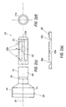
- Figure 4 illustrates a lateral view of an obturator used with the cannula assembly of Figure 3;
- Figures 5(a)-(c) illustrate a top view, a partial cross-sectional view and a lateral view, respectively, of the cannula (inner tube) of the cannula assembly of Figure 3;
- Figures 6(a)-(f) illustrate various views of the proximal end of the cannula (inner tube) of Figures 5(a)-(c);
- Figures 7(a)-(e) illustrate various views of the obturator of Figure 4;
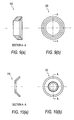
- Figures 8(a)-(d) illustrate various views of the cannula cap of the cannula assembly of Figure 3;
- Figures 9(a) and 9(b) illustrate a cross-sectional view and a top view, respectively, of the end cap of the cannula assembly of Figure 3;
- Figures 10(a) and 10(b) illustrate a cross-sectional view and a top view, respectively, of the pressure ring of the cannula assembly of Figure 3;
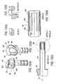
- FIGS 11(a)-(d) illustrate various views of the slider (outer tube) of the cannula assembly of Figure 3;
- Figures 12(a)-(d) illustrate additional views of the slider (outer tube) of the cannula assembly of Figure 3;
- Figure 13 illustrates a surgical site of a shoulder undergoing surgery with the cannula assembly of Figure 3 and with the slider (outer tube) fully expanded within the surgical site;
- Figure 12 illustrates a top view of the cannula assembly of Figure 3 (in the fully expanded position);
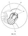
- Figure 15 illustrates a surgical site of a shoulder undergoing surgery with the cannula assembly of Figure 3 and with the slider (outer tube) in a retracted position within the surgical site;
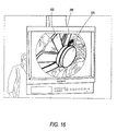
- Figure 16 illustrates a radiological image of a surgical site undergoing surgery, with the cannula assembly of Figure 3 and with the slider (outer tube) fully expanded within the surgical site;
- Figure 17 illustrates a shoulder undergoing surgery, with the cannula assembly of Figure 3 and with the slider (outer tube) in the retracted position, and also with a pressure ring outside the surgical site;
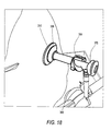
- Figure 18 illustrates a shoulder undergoing surgery, with the cannula assembly of Figure 3 and with the slider (outer tube) in the fully expanded position (inside the surgical site), and also with a pressure ring outside the surgical site.
- the present invention provides a cannula assembly comprising an elongated cannula having an inner tube that is designed to cooperate with a corresponding outer cylindrical sleeve.
- the inner tube is slidably moveable relative to the outer cylindrical sleeve in at least one direction.
- the invention also provides a method of conducting surgery by: (i) providing a cannula assembly having an inner tube in cooperation with a corresponding outer cylindrical sleeve, the inner tube being slidably moveable relative to the cylindrical sleeve in at least one direction; and (ii) conducting at least one surgical procedure employing the cannula assembly.
- the present invention provides a cannula assembly comprising an elongated cannula having an inner tube that is slidably moveable relative to a cylindrical sleeve.
- the distal end of the inner tube includes a plurality of distal radially expanding fingers that are designed to pass through corresponding windows in a distal portion of the cylindrical sleeve.
- the invention provides a cannula assembly with an elongated cannula having an inner tube that is slidably moveable relative to a cylindrical sleeve (outer tube) in both a longitudinal and a rotational direction.
- the cannula assembly comprises a deployment mechanism (for example, a cam mechanism) wherein a member of the inner tube (for example, a protuberance) is designed to move in a first direction (for example, a rotary motion or a helical motion) on an open ramp of a proximal end of the outer tube and to cause a plurality of fingers at a distal portion of the cylindrical sleeve (outer tube) to move in a second direction, which is different from the first direction.
- a deployment mechanism for example, a cam mechanism
- the second direction is a longitudinal direction to allow the plurality of segments to fold and expand in a "flower” type or “mushroom” type arrangement relative to the longitudinal axis of the outer tube.
- the cannula assembly may be optionally provided with a pressure ring designed to provide additional stability to the cannula during surgery.
- the present invention also provides methods of conducting minimally invasive surgery by: (i) providing a cannula assembly of the present invention; and (ii) conducting at least one surgical procedure employing the cannula.
- Figures 1(a)-(e) illustrate an exemplary embodiment of a cannula assembly 100 of the present invention.
- Cannula assembly 100 includes a cannula 50 and a corresponding cylindrical sleeve or outer tube 80.
- the elongated body 10 of cannula 50 is slidably moveable relative to the cylindrical sleeve 80.
- the elongated body 10 of cannula 50 has a distal end 12 and a proximal end 13, as shown in Figure 1(e), for example.
- Radially expanding fingers 55 are provided at distal end 12 of the body 10.
- Cylindrical sleeve 80 is cannulated and designed to receive body 10 of cannula 50. As shown in Figures 1(a)-(e), cylindrical sleeve 80 is provided with a flange 82 at its proximal end and with a plurality of windows 88 at its distal end.
- the radially-expanding fingers 55 can have various shapes and configurations (for example, the rectangular configuration shown in Figure 1(d)).
- the number of fingers 55 of the body 10 corresponds to the number of windows 88 provided on the cylindrical sleeve 80.
- windows 88 have a shape and geometry that is complementary to that of the fingers 55.
- the fingers expand radially outwardly and pass through (through lateral movement, for example) the windows 88 provided in the cylindrical sleeve 80.
- the fingers 55 are designed to engage the inner surface of the body wall to prevent the accidental withdrawal of the cannula from the body. Once engaged, the fingers, passing radially through and beyond windows 88, secure the cannula assembly 100 within an anatomical body.
- a surgeon using only fingertip pressure against the turning member (handle) 70 of the cannula 50 simply pushes body 10 of cannula 50 through outer tube 80 so that threads 71 on the body 10 of cannula 50 engage corresponding threads 81 on the proximal end of the cylindrical sleeve (outer tube) 80, thereby urging the cylindrical sleeve 80 to slide along the cannula body 10.
- This movement causes fingers 55 to expand and deploy through windows 88 in a snap-fit relationship.
- the operator can also withdraw the cannula body 51 outwardly. Fingers 55 are maintained in their expanded and deployed condition by firmly and securely engaging the turning member 70 with the threads.
- Figures 2(a)-(e) illustrate another "inside-out" exemplary embodiment of a cannula assembly 200 of the present invention, according to which a first tube (or cannula) 250 ( Figures 2(c)-(e)) is concentrically movable relative to a corresponding cylindrical sleeve or outer tube 280 ( Figures 2(a)-(b)).
- the elongated body 210 of cannula 250 has a distal end 212 and a proximal end 213, as shown in Figure 2(c), for example.
- a plurality of spaced apart segments 255 are provided at distal end 212 of the body 210 for expanding and securely engaging a distal portion of cylindrical sleeve 280, as explained in detail below.
- the spaced apart segments 255 are circumferentially disposed about and longitudinally co-extensive with the tubular body 210 and secured to the distal end of the cylindrical sleeve such that, when the cylindrical sleeve is slidably urged along the body 210 toward the distal end 212 of the body 210, segments 255 are caused to deploy enabling those members to retract and retain torn or fragmented soft tissue within an anatomical cavity (and also to anchor the cannula within an anatomical cavity with a minimum of penetration of the cannula into an anatomical cavity).
- Segments 255 at the distal end of the inner tube 210 are manufactured so as to be capable of being flexed intermediate their ends enabling them to be fully deployed and expanded within an anatomical cavity. As illustrated in Figures 2(c) and 2(e), segments 255 are in a first position, preferably approximately parallel to longitudinal axis 201. Segments 255 are configured to bend or flex at a midpoint hinge 255a (point A), a proximal hinge 255b (point B) and a distal hinge 255c (point C).
- the flexible hinges may have a thickness that is less than the thickness of the wall of each segment 255 to facilitate bending between the first position and a second (for example, a partially-deployed or a fully-deployed position).
- the hinged structure advantageously provides segments 255 with a controlled degree of longitudinal rigidity in the first position, a bias to the first position and flexibility to move between the first position and the second (partially-deployed or fully-deployed) position.
- segments 255 are in the second (deployed) position with midpoint hinge 255a forming an approximately 90 degree angle and hinges 255b and 255c at angles of approximately forty-five degrees relative to the longitudinal axis 201.
- segments 255 in the second (deployed) position may be at any position between about parallel and about perpendicular to the longitudinal axis.
- Segments 255 can also vary in number, length, outer surface width and radial thickness, depending upon their intended application.
- the means to secure the cylindrical sleeve (outer tube) 280 to the inner tube 210 of cannula 250 (as the cylindrical sleeve is slidably moved along the tubular body) may be provided by any suitable and conventional means, such as at least one detent or aperture 253 ( Figure 2(c)) which mate with at least one protrusion 283 ( Figure 2(a)) at the proximate end of the outer cylindrical sleeve.
- most distal end 284 of the outer tube 280 is provided with a smaller diameter tip 284a (Figure 2(a)) to allow most distal end 212a of the inner tube 250 to stop thereon, for increased retention and a closer fitting relationship.
- Other means such as spot welding or fusion, for example, may also be readily used as will be apparent to those skilled in the art.
- an operator for example, a surgeon
- fingertip pressure against member 270 a cup or a dam
- cannula body 210 slides along the cylindrical sleeve 280.
- This movement causes segments 255 to fold at the hinges and deploy.
- the operator can also withdraw the cannula body 210 outwardly. Segments 255 are maintained in their partially deployed position by firmly and securely engaging protrusions 283 with detents 253.
- Figures 3, 5, 6 and 8-18 illustrate various views of different components of cannula assembly 300 formed according to another exemplary embodiment of the present invention.
- Figures 4 and 7 illustrate various views of an obturator 400 that may be used with the cannula assembly 300, as known in the art.
- cannula assembly 300 also includes an elongated cannula having an inner tube that is slidably moveable relative to a cylindrical sleeve (outer tube).
- the tubes are designed to slidably move relative to each other in both a longitudinal and a rotational direction.
- a deployment mechanism (for example, a cam mechanism) allows a member of the inner tube (for example, a portal such as an irrigation fluid portal) to move in a first direction (for example, by a helical motion) on an open ramp of the outer tube and to cause a plurality of segments at a distal portion of the cylindrical sleeve (outer tube) to move in a second direction (for example, a longitudinal direction).
- the cannula assembly may be optionally provided with a pressure ring designed to provide additional stability to the cannula during surgery.
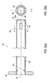
- FIG. 3 illustrates an expanded view of the various components of the cannula assembly 300 of the present invention.
- a first tube (or inner cannula) 350 ( Figures 3, 5 and 6) is concentrically movable relative to a corresponding cylindrical sleeve or outer tube 380 ( Figures 3, 11 and 12).
- Cannula assembly 300 also includes a cannula cap 302 ( Figures 3 and 8(a)-(d)), slot dams 301 (to be placed on locator pins and rotated about 90 degrees relative to each other), an end cap 320 ( Figures 3, 9(a) and 9(b)) and a pressure ring 310 ( Figures 3, 10(a) and 10(b)).
- Elongated body 351 of cannula 350 has a distal end 312a and a proximal end 313a, as shown in Figure 5(c), for example.
- Cup or dam 370 and a fluid port (for example, an irrigation fluid port) 360 are provided at the proximal end 313a of the cannula 350. Additional views of dam 370 and fluid port 360 are provided in Figures 5(a)-(c), Figures 6(a)-(b) and Figures 6(d)-(f).
- Cap 365 for example, a lanyard cap
- lanyard 363 are connected to fluid port 360, as shown in Figure 3.
- fluid port 360 is designed to rotate on an open ramp of the outer tube (slider) 380 and to securely engage and rest within a detent of the open ramp.
- Protuberance 352 at the distal end 312a of the body 351 is designed to securely engage and mate end cap 320 ( Figures 9(a) and 9(b)).
- Protuberance 352 may be fixedly attached to the end cap 320 by spot welding, ultrasonic welding or fusion, for example, or by other means known to those skilled in the art.
- Elongated body 381 of outer tube (slider) 380 also has a distal end 312 and a proximal end 313, as shown in Figure 11(b), for example.
- Elongated body 381 includes an open ramp 399 provided at the proximal end 313 and a plurality of spaced apart segments or members 388 provided at distal end 312.
- the open ramp 399 (shown in Figures 11(a)-(c) and Figures 12(a) and 12(b))) has an outer surface 395, at least a portion of which is provided with a helical configuration.
- region 396 of the ramp 399 has a helical configuration and is delimited by point A and point B (corresponding to detent 399a) on the outer surface 395.
- rotation of the cap 370 relative to the outer tube 380 allows fluid port 360 of cannula 350 to travel on helical region 396 of the ramp 399 from point A (unexpanded position) to point B (fully-expanded or fully-deployed position) and to rest on detent 399a (corresponding to point B) when the device is in the fully-deployed position.
- open ramp 399 may be also provided with a plurality of fenestrations or cutouts 399b ( Figure 11 (a)) and/or protrusions 399c ( Figure 12(a)) that mold easily and that allow a user to easily grasp and securely rotate the device.
- Segments 388 are provided at the distal end 312 of the body 381 for expanding within a body cavity, as explained below.
- the spaced apart segments 388 are circumferentially disposed about and longitudinally co-extensive with the tubular body 381 and secured to the distal end of the slider (cylindrical sleeve or outer tube) 380 such that, when the inner cannula is slidably urged along the tubular body toward the distal end of the tubular body, segments 388 are caused to pivot at the hinges and deploy radially outwardly, enabling those segments to anchor the cannula within an anatomical cavity with a minimum of penetration of the cannula into an anatomical cavity.
- Segments 388 at the distal end of the outer tube 380 are similar to segments 255 described above with reference to the second embodiment, and are manufactured so as to be capable of being flexed intermediate their ends enabling them to be fully deployed and expanded within an anatomical cavity. As illustrated in Figure 12(d), segments 388 are in a first position, preferably approximately parallel to longitudinal axis 301. Segments 388 are configured to bend or flex at a midpoint hinge 388a (point A), a proximal hinge 388b (point B) and a distal hinge 388c (point C).
- the flexible hinges may have a thickness that is less than the thickness of the wall of each segment 388 to facilitate bending between the first position and a second (for example, a deployed or a fully-deployed position).
- the hinged structure advantageously provides segments 388 with a controlled degree of longitudinal rigidity in the first position, a bias to the first position and flexibility to move between the first position and the second deployed position.
- segments 388 are in the second (deployed) position with midpoint hinge 388a forming an approximately 90 degree angle and hinges 388b and 388c at angles of approximately forty-five degrees relative to longitudinal axis 301 (as shown in Figures 13 and 14, for example).
- segments 388 in the second (deployed) position may be at any position between about parallel and about perpendicular to the longitudinal axis.
- Figure 15 illustrates segments 388 partially deployed and forming an angle ⁇ of about 160 degrees at point A (midpoint hinge 388a).
- Segments 388 may be also folded or extended in a position about perpendicular to the longitudinal axis 301 of the outer tube 380 (as shown, for example, in Figure 16). Segments 388 can also vary in number, length, outer surface width and radial thickness, depending upon their intended application.
- Counter-pressure ring 310 ( Figure 3 and Figures 10(a) and 10(b)) is selectively longitudinally positionable on outer tube 380.
- Counter-pressure ring 310 may have various configurations and geometries, for example, such as the one disclosed in U.S. Patent Publication No. 2007/0162066 .
- Counter-pressure ring 310 is preferably made of a material with sufficient structural integrity to function as a counter-pressure to the deployed segments 388.
- Counter-pressure ring 310 can indicate and/or assess the amount of pressure applied to the patient's skin.
- counter-pressure ring 310 is at least partially fabricated of a transparent material such that a visual inspection can be made of the skin of the patient during the surgical procedure.
- Alternative visual indications can be provided by through holes in ring 310 that allow direct visibility to the skin.
- Ring 310 can also include one or more pressure sensors and indicators that measure the amount of applied pressure.
- the planar proximal surface of ring 310 may be optionally tapered in the vicinity of the outer edge to minimize the stress that is applied to the body of the patient.
- an operator inserts inner tube or cannula 350 within outer tube 380 so that fluid port 360 of cannula 350 rests approximately on point A of open ramp 399 of outer tube 380. Grasping open ramp 399, the operator then rotates fluid port 360 along the helical portion 396 of the ramp 399 (from point A to point B), so that cannula body 351 slides along the cylindrical sleeve 380 causing segments 388 to begin folding and expanding (deploying).
- segments 388 achieve a fully-deployed state (second position) and stop deploying when fluid port 360 fully rests on detent 399a of the open ramp 399 (point B).
- the operator inserts inner tube or cannula 350 within outer tube 380 so that fluid port 360 of cannula 350 rests approximately on point A of open ramp 399 of outer tube 380. Grasping open ramp 399, the operator then rotates the cylindrical sleeve 380 so that the fluid port 360 travels along the helical portion 396 of the ramp 399 (from point A to point B), to allow cannula body 351 to slide along the cylindrical sleeve 380 and to cause segments 388 to begin folding and expanding (deploying).
- the length of the body 381 decreases to a minimum length that corresponds to the segments 388 achieving a fully-deployed state (second position).
- the segments 399 stop deploying when fluid port 360 fully rests on detent 399a of the open ramp 399 (point B).
- Figures 17 and 18 illustrate, for example, sequential steps that can be employed in using the cannula assembly of the present invention.
- the cannula assembly 300 is shown being inserted through a body wall 25 and into an anatomical cavity such as a knee joint.
- anatomical cavity such as a knee joint.
- insertion is typically made through a pre-formed incision, such insertion and penetration generally result in torn and fragmented soft tissue which can obstruct or otherwise interfere with the use of an auxiliary surgical instrument.
- Such obstruction or interference is virtually eliminated by using the cannula of the invention.
- an operator urges cannula body 351 to slide along cylindrical sleeve 380 in the direction of arrow C, as illustrated in Figure 3.
- This causes segments 388 to expand and deploy within the cavity, as shown in Figures 13-16.
- fluid port 360 travels on helical ramp 399 from point A to point B ( Figure 18) until segments 388 are fully-deployed within the cavity, contacting and engaging the inner surface of the body wall 25.
- the segments 388 are locked in their fully-expanded and deployed condition (second position).
- the cannula body 351 is also firmly secured within the body wall 25 by counter-pressure ring 310 in direct contact with the patient.
- Counter-pressure ring 310 stabilizes the angular relationship between cannula 300 and the patient's body.
- the combination of deployed segments 388 and ring 310 provides a fluid tight seal between the cannula and the patient's body and accommodate the pulling back on the cannula during surgical procedures without breaking the seal to provide increased visibility within the joint or body cavity of the patient.
- the materials used to fabricate the various components of the cannula assembly 100, 200, 300 of the present invention are not critical provided they are suitable for use in surgical procedures.
- all components of the cannula assembly 100, 200, 300 of the present invention are preferably fabricated from well known and commercially available plastic materials that are suitable for use in surgical procedures, for example, polymers, composites, metals, glass, or combination of these materials, among many others.
- At least some of the components (and preferably all the components) may be formed of transparent or clear materials to allow easy visualization of the surgical site and/or of auxiliary surgical instruments.
- the cannula assembly of the present invention may be preferably a reusable assembly that can be disassembled and sterilized, but it can also be constructed to be a disposable device that is intended for single use applications.
- the cannula assembly 100, 200, 300 of the invention can readily be used in large body cavities such as the abdomen, it is particularly useful in smaller cavities such as joints (i.e., knees, shoulders, elbows, ankles, and the like).
- joints i.e., knees, shoulders, elbows, ankles, and the like.
- the joint is typically inflated with water as opposed to a gas which is typically used in abdominal surgical procedures as the surgical procedures performed within a joint are significantly different from those performed within an abdominal cavity.
- the inside of a joint such as the knee is lined with a layer of a friable tissue called the synovium which is about fractions of a centimeter thick.
- the synovial tissue is often inflamed and is also frequently torn and fragmented.
- a patella fat pad or blob of fat tissue
- inflamed and/or torn and fragmented synovial tissue and the patella fat pad in the knee joint serve to restrict and impede visualization of the joint cavity by the surgeon. This restricted vision is completely eliminated when using the cannula assembly of the present invention.
Abstract
Description
- The present invention relates to methods and apparatus for surgical procedures.
- Minimally invasive surgeries (such as endoscopic surgery) are performed via portals through which a variety of elongated instruments may be passed to gain access to an internal surgical site. Cannulas are often inserted into portals to provide a convenient passageway through which the various instruments may pass. When cannulas are inserted through portals formed in walls of the body, it is desirable that the ends of the cannulas (disposed within the body) remain as close as possible to internal surfaces of the walls such that the ends of the cannulas do not protrude very far into the body to avoid inadvertent contact with and damage to anatomical structures, such as organs or nerves, for example. More importantly, when medical instruments are inserted through the cannulas, it is desirable that the cannulas remain stable and do not easily back out of the walls to negatively affect the surgical procedure.
- Accordingly, there is a need for cannulas that are used in minimally invasive procedures and that remain stable within the body yet very close to internal surfaces of the walls.
- The present invention provides cannula assemblies that comprise an elongated cannula having an inner tube that is designed to cooperate with a corresponding outer tube. The inner and outer tubes are slidably moveable relative to each other in at least one direction.
- Other features and advantages of the present invention will become apparent from the following description of the invention, which refers to the accompanying drawing.
- Figures 1(a)-(e) illustrate various views of a cannula assembly according to a first exemplary embodiment of the present invention;
- Figures 2(a)-(e) illustrate various views of components of a cannula assembly according to a second exemplary embodiment of the present invention;
- Figure 3 illustrates an expanded view of a cannula assembly according to a third exemplary embodiment of the present invention;
- Figure 4 illustrates a lateral view of an obturator used with the cannula assembly of Figure 3;
- Figures 5(a)-(c) illustrate a top view, a partial cross-sectional view and a lateral view, respectively, of the cannula (inner tube) of the cannula assembly of Figure 3;
- Figures 6(a)-(f) illustrate various views of the proximal end of the cannula (inner tube) of Figures 5(a)-(c);
- Figures 7(a)-(e) illustrate various views of the obturator of Figure 4;
- Figures 8(a)-(d) illustrate various views of the cannula cap of the cannula assembly of Figure 3;
- Figures 9(a) and 9(b) illustrate a cross-sectional view and a top view, respectively, of the end cap of the cannula assembly of Figure 3;
- Figures 10(a) and 10(b) illustrate a cross-sectional view and a top view, respectively, of the pressure ring of the cannula assembly of Figure 3;
- Figures 11(a)-(d) illustrate various views of the slider (outer tube) of the cannula assembly of Figure 3;
- Figures 12(a)-(d) illustrate additional views of the slider (outer tube) of the cannula assembly of Figure 3;
- Figure 13 illustrates a surgical site of a shoulder undergoing surgery with the cannula assembly of Figure 3 and with the slider (outer tube) fully expanded within the surgical site;
- Figure 12 illustrates a top view of the cannula assembly of Figure 3 (in the fully expanded position);
- Figure 15 illustrates a surgical site of a shoulder undergoing surgery with the cannula assembly of Figure 3 and with the slider (outer tube) in a retracted position within the surgical site;
- Figure 16 illustrates a radiological image of a surgical site undergoing surgery, with the cannula assembly of Figure 3 and with the slider (outer tube) fully expanded within the surgical site;
- Figure 17 illustrates a shoulder undergoing surgery, with the cannula assembly of Figure 3 and with the slider (outer tube) in the retracted position, and also with a pressure ring outside the surgical site; and
- Figure 18 illustrates a shoulder undergoing surgery, with the cannula assembly of Figure 3 and with the slider (outer tube) in the fully expanded position (inside the surgical site), and also with a pressure ring outside the surgical site.
- In the following detailed description, reference is made to various specific embodiments in which the invention may be practiced. These embodiments are described with sufficient detail to enable those skilled in the art to practice the invention, and it is to be understood that other embodiments may be employed, and that structural and logical changes may be made without departing from the spirit or scope of the present invention.
- The present invention provides a cannula assembly comprising an elongated cannula having an inner tube that is designed to cooperate with a corresponding outer cylindrical sleeve. The inner tube is slidably moveable relative to the outer cylindrical sleeve in at least one direction. The invention also provides a method of conducting surgery by: (i) providing a cannula assembly having an inner tube in cooperation with a corresponding outer cylindrical sleeve, the inner tube being slidably moveable relative to the cylindrical sleeve in at least one direction; and (ii) conducting at least one surgical procedure employing the cannula assembly.
- According to an exemplary embodiment, the present invention provides a cannula assembly comprising an elongated cannula having an inner tube that is slidably moveable relative to a cylindrical sleeve. The distal end of the inner tube includes a plurality of distal radially expanding fingers that are designed to pass through corresponding windows in a distal portion of the cylindrical sleeve.
- In another exemplary embodiment, the invention provides a cannula assembly with an elongated cannula having an inner tube that is slidably moveable relative to a cylindrical sleeve (outer tube) in both a longitudinal and a rotational direction. The cannula assembly comprises a deployment mechanism (for example, a cam mechanism) wherein a member of the inner tube (for example, a protuberance) is designed to move in a first direction (for example, a rotary motion or a helical motion) on an open ramp of a proximal end of the outer tube and to cause a plurality of fingers at a distal portion of the cylindrical sleeve (outer tube) to move in a second direction, which is different from the first direction. In an exemplary embodiment, the second direction is a longitudinal direction to allow the plurality of segments to fold and expand in a "flower" type or "mushroom" type arrangement relative to the longitudinal axis of the outer tube. The cannula assembly may be optionally provided with a pressure ring designed to provide additional stability to the cannula during surgery.
- The present invention also provides methods of conducting minimally invasive surgery by: (i) providing a cannula assembly of the present invention; and (ii) conducting at least one surgical procedure employing the cannula.
- Referring now to the drawings, where like elements are designated by like reference numerals, Figures 1(a)-(e) illustrate an exemplary embodiment of a
cannula assembly 100 of the present invention. Cannulaassembly 100 includes acannula 50 and a corresponding cylindrical sleeve orouter tube 80. Theelongated body 10 ofcannula 50 is slidably moveable relative to thecylindrical sleeve 80. - The
elongated body 10 ofcannula 50 has adistal end 12 and aproximal end 13, as shown in Figure 1(e), for example. Radially expandingfingers 55 are provided atdistal end 12 of thebody 10. -
Cylindrical sleeve 80 is cannulated and designed to receivebody 10 ofcannula 50. As shown in Figures 1(a)-(e),cylindrical sleeve 80 is provided with aflange 82 at its proximal end and with a plurality ofwindows 88 at its distal end. - The radially-expanding
fingers 55 can have various shapes and configurations (for example, the rectangular configuration shown in Figure 1(d)). The number offingers 55 of thebody 10 corresponds to the number ofwindows 88 provided on thecylindrical sleeve 80. Preferably,windows 88 have a shape and geometry that is complementary to that of thefingers 55. In this manner, whenbody 10 ofcannula 50 is inserted in the cylindrical sleeve 80 (as illustrated in Figures 1(a)-(c)), the fingers expand radially outwardly and pass through (through lateral movement, for example) thewindows 88 provided in thecylindrical sleeve 80. Thefingers 55 are designed to engage the inner surface of the body wall to prevent the accidental withdrawal of the cannula from the body. Once engaged, the fingers, passing radially through and beyondwindows 88, secure thecannula assembly 100 within an anatomical body. - To operate, a surgeon using only fingertip pressure against the turning member (handle) 70 of the
cannula 50 simply pushesbody 10 ofcannula 50 throughouter tube 80 so thatthreads 71 on thebody 10 ofcannula 50 engagecorresponding threads 81 on the proximal end of the cylindrical sleeve (outer tube) 80, thereby urging thecylindrical sleeve 80 to slide along thecannula body 10. This movement causesfingers 55 to expand and deploy throughwindows 88 in a snap-fit relationship. As the operator continues to expand and deploy thefingers 55 in this manner, the operator can also withdraw the cannula body 51 outwardly.Fingers 55 are maintained in their expanded and deployed condition by firmly and securely engaging theturning member 70 with the threads. - Figures 2(a)-(e) illustrate another "inside-out" exemplary embodiment of a
cannula assembly 200 of the present invention, according to which a first tube (or cannula) 250 (Figures 2(c)-(e)) is concentrically movable relative to a corresponding cylindrical sleeve or outer tube 280 (Figures 2(a)-(b)). - The
elongated body 210 ofcannula 250 has adistal end 212 and aproximal end 213, as shown in Figure 2(c), for example. A plurality of spacedapart segments 255 are provided atdistal end 212 of thebody 210 for expanding and securely engaging a distal portion ofcylindrical sleeve 280, as explained in detail below. The spacedapart segments 255 are circumferentially disposed about and longitudinally co-extensive with thetubular body 210 and secured to the distal end of the cylindrical sleeve such that, when the cylindrical sleeve is slidably urged along thebody 210 toward thedistal end 212 of thebody 210,segments 255 are caused to deploy enabling those members to retract and retain torn or fragmented soft tissue within an anatomical cavity (and also to anchor the cannula within an anatomical cavity with a minimum of penetration of the cannula into an anatomical cavity). -
Segments 255 at the distal end of theinner tube 210 are manufactured so as to be capable of being flexed intermediate their ends enabling them to be fully deployed and expanded within an anatomical cavity. As illustrated in Figures 2(c) and 2(e),segments 255 are in a first position, preferably approximately parallel tolongitudinal axis 201.Segments 255 are configured to bend or flex at amidpoint hinge 255a (point A), aproximal hinge 255b (point B) and adistal hinge 255c (point C). The flexible hinges may have a thickness that is less than the thickness of the wall of eachsegment 255 to facilitate bending between the first position and a second (for example, a partially-deployed or a fully-deployed position). The hinged structure advantageously providessegments 255 with a controlled degree of longitudinal rigidity in the first position, a bias to the first position and flexibility to move between the first position and the second (partially-deployed or fully-deployed) position. - In an exemplary embodiment,
segments 255 are in the second (deployed) position withmidpoint hinge 255a forming an approximately 90 degree angle and hinges 255b and 255c at angles of approximately forty-five degrees relative to thelongitudinal axis 201. In another exemplary embodiment,segments 255 in the second (deployed) position may be at any position between about parallel and about perpendicular to the longitudinal axis.Segments 255 can also vary in number, length, outer surface width and radial thickness, depending upon their intended application. - The means to secure the cylindrical sleeve (outer tube) 280 to the
inner tube 210 of cannula 250 (as the cylindrical sleeve is slidably moved along the tubular body) may be provided by any suitable and conventional means, such as at least one detent or aperture 253 (Figure 2(c)) which mate with at least one protrusion 283 (Figure 2(a)) at the proximate end of the outer cylindrical sleeve. In addition, mostdistal end 284 of theouter tube 280 is provided with asmaller diameter tip 284a (Figure 2(a)) to allow mostdistal end 212a of theinner tube 250 to stop thereon, for increased retention and a closer fitting relationship. Other means such as spot welding or fusion, for example, may also be readily used as will be apparent to those skilled in the art. - In use, an operator (for example, a surgeon) using only fingertip pressure against member 270 (a cup or a dam) of
cannula 250 simply pushesmember 270 thereby urgingcannula body 210 to slide along thecylindrical sleeve 280. This movement causessegments 255 to fold at the hinges and deploy. As the operator continues to deploysegments 255 in this manner, the operator can also withdraw thecannula body 210 outwardly.Segments 255 are maintained in their partially deployed position by firmly and securely engagingprotrusions 283 withdetents 253. - Figures 3, 5, 6 and 8-18 illustrate various views of different components of
cannula assembly 300 formed according to another exemplary embodiment of the present invention. Figures 4 and 7 illustrate various views of anobturator 400 that may be used with thecannula assembly 300, as known in the art. - The exemplary embodiment illustrated in Figures 3, 5, 6 and 8-18 is similar to the above-described embodiments in that
cannula assembly 300 also includes an elongated cannula having an inner tube that is slidably moveable relative to a cylindrical sleeve (outer tube). However, in this exemplary third embodiment, the tubes are designed to slidably move relative to each other in both a longitudinal and a rotational direction. As detailed below, a deployment mechanism (for example, a cam mechanism) allows a member of the inner tube (for example, a portal such as an irrigation fluid portal) to move in a first direction (for example, by a helical motion) on an open ramp of the outer tube and to cause a plurality of segments at a distal portion of the cylindrical sleeve (outer tube) to move in a second direction (for example, a longitudinal direction). The cannula assembly may be optionally provided with a pressure ring designed to provide additional stability to the cannula during surgery. - Reference is now made to Figure 3 which illustrates an expanded view of the various components of the
cannula assembly 300 of the present invention. A first tube (or inner cannula) 350 (Figures 3, 5 and 6) is concentrically movable relative to a corresponding cylindrical sleeve or outer tube 380 (Figures 3, 11 and 12).Cannula assembly 300 also includes a cannula cap 302 (Figures 3 and 8(a)-(d)), slot dams 301 (to be placed on locator pins and rotated about 90 degrees relative to each other), an end cap 320 (Figures 3, 9(a) and 9(b)) and a pressure ring 310 (Figures 3, 10(a) and 10(b)). -
Elongated body 351 ofcannula 350 has adistal end 312a and aproximal end 313a, as shown in Figure 5(c), for example. Cup ordam 370 and a fluid port (for example, an irrigation fluid port) 360 are provided at theproximal end 313a of thecannula 350. Additional views ofdam 370 andfluid port 360 are provided in Figures 5(a)-(c), Figures 6(a)-(b) and Figures 6(d)-(f). Cap 365 (for example, a lanyard cap) andlanyard 363 are connected tofluid port 360, as shown in Figure 3. As detailed below,fluid port 360 is designed to rotate on an open ramp of the outer tube (slider) 380 and to securely engage and rest within a detent of the open ramp.Protuberance 352 at thedistal end 312a of thebody 351 is designed to securely engage and mate end cap 320 (Figures 9(a) and 9(b)).Protuberance 352 may be fixedly attached to theend cap 320 by spot welding, ultrasonic welding or fusion, for example, or by other means known to those skilled in the art. -
Elongated body 381 of outer tube (slider) 380 also has adistal end 312 and a proximal end 313, as shown in Figure 11(b), for example.Elongated body 381 includes anopen ramp 399 provided at the proximal end 313 and a plurality of spaced apart segments ormembers 388 provided atdistal end 312. The open ramp 399 (shown in Figures 11(a)-(c) and Figures 12(a) and 12(b)) has anouter surface 395, at least a portion of which is provided with a helical configuration. As shown in Figure 11(a), for example,region 396 of theramp 399 has a helical configuration and is delimited by point A and point B (corresponding todetent 399a) on theouter surface 395. - As detailed below and with reference to Figure 11(a), for example, rotation of the
cap 370 relative to theouter tube 380 allowsfluid port 360 ofcannula 350 to travel onhelical region 396 of theramp 399 from point A (unexpanded position) to point B (fully-expanded or fully-deployed position) and to rest ondetent 399a (corresponding to point B) when the device is in the fully-deployed position. To allow movement of thefluid port 360 onhelical region 396,open ramp 399 may be also provided with a plurality of fenestrations orcutouts 399b (Figure 11 (a)) and/or protrusions 399c (Figure 12(a)) that mold easily and that allow a user to easily grasp and securely rotate the device. -
Segments 388 are provided at thedistal end 312 of thebody 381 for expanding within a body cavity, as explained below. The spaced apartsegments 388 are circumferentially disposed about and longitudinally co-extensive with thetubular body 381 and secured to the distal end of the slider (cylindrical sleeve or outer tube) 380 such that, when the inner cannula is slidably urged along the tubular body toward the distal end of the tubular body,segments 388 are caused to pivot at the hinges and deploy radially outwardly, enabling those segments to anchor the cannula within an anatomical cavity with a minimum of penetration of the cannula into an anatomical cavity. -
Segments 388 at the distal end of theouter tube 380 are similar tosegments 255 described above with reference to the second embodiment, and are manufactured so as to be capable of being flexed intermediate their ends enabling them to be fully deployed and expanded within an anatomical cavity. As illustrated in Figure 12(d),segments 388 are in a first position, preferably approximately parallel tolongitudinal axis 301.Segments 388 are configured to bend or flex at amidpoint hinge 388a (point A), aproximal hinge 388b (point B) and a distal hinge 388c (point C). The flexible hinges may have a thickness that is less than the thickness of the wall of eachsegment 388 to facilitate bending between the first position and a second (for example, a deployed or a fully-deployed position). The hinged structure advantageously providessegments 388 with a controlled degree of longitudinal rigidity in the first position, a bias to the first position and flexibility to move between the first position and the second deployed position. - In an exemplary embodiment,
segments 388 are in the second (deployed) position withmidpoint hinge 388a forming an approximately 90 degree angle and hinges 388b and 388c at angles of approximately forty-five degrees relative to longitudinal axis 301 (as shown in Figures 13 and 14, for example). In another exemplary embodiment,segments 388 in the second (deployed) position may be at any position between about parallel and about perpendicular to the longitudinal axis. For example, Figure 15 illustratessegments 388 partially deployed and forming an angle α of about 160 degrees at point A (midpoint hinge 388a).Segments 388 may be also folded or extended in a position about perpendicular to thelongitudinal axis 301 of the outer tube 380 (as shown, for example, in Figure 16).Segments 388 can also vary in number, length, outer surface width and radial thickness, depending upon their intended application. - Counter-pressure ring 310 (Figure 3 and Figures 10(a) and 10(b)) is selectively longitudinally positionable on
outer tube 380.Counter-pressure ring 310 may have various configurations and geometries, for example, such as the one disclosed inU.S. Patent Publication No. 2007/0162066 .Counter-pressure ring 310 is preferably made of a material with sufficient structural integrity to function as a counter-pressure to the deployedsegments 388. -
Counter-pressure ring 310 can indicate and/or assess the amount of pressure applied to the patient's skin. In a preferred embodiment,counter-pressure ring 310 is at least partially fabricated of a transparent material such that a visual inspection can be made of the skin of the patient during the surgical procedure. Alternative visual indications can be provided by through holes inring 310 that allow direct visibility to the skin.Ring 310 can also include one or more pressure sensors and indicators that measure the amount of applied pressure. The planar proximal surface ofring 310 may be optionally tapered in the vicinity of the outer edge to minimize the stress that is applied to the body of the patient. - In use, an operator (for example, a surgeon) inserts inner tube or
cannula 350 withinouter tube 380 so thatfluid port 360 ofcannula 350 rests approximately on point A ofopen ramp 399 ofouter tube 380. Graspingopen ramp 399, the operator then rotatesfluid port 360 along thehelical portion 396 of the ramp 399 (from point A to point B), so thatcannula body 351 slides along thecylindrical sleeve 380 causingsegments 388 to begin folding and expanding (deploying). - As the operator continues to rotate
cannula 350 relative to theouter tube 380,segments 388 achieve a fully-deployed state (second position) and stop deploying whenfluid port 360 fully rests ondetent 399a of the open ramp 399 (point B). - Alternatively, the operator (for example, a surgeon) inserts inner tube or
cannula 350 withinouter tube 380 so thatfluid port 360 ofcannula 350 rests approximately on point A ofopen ramp 399 ofouter tube 380. Graspingopen ramp 399, the operator then rotates thecylindrical sleeve 380 so that thefluid port 360 travels along thehelical portion 396 of the ramp 399 (from point A to point B), to allowcannula body 351 to slide along thecylindrical sleeve 380 and to causesegments 388 to begin folding and expanding (deploying). As the operator continues to rotate theopen ramp 399 and theouter tube 380, the length of thebody 381 decreases to a minimum length that corresponds to thesegments 388 achieving a fully-deployed state (second position). Thesegments 399 stop deploying whenfluid port 360 fully rests ondetent 399a of the open ramp 399 (point B). - Figures 17 and 18 illustrate, for example, sequential steps that can be employed in using the cannula assembly of the present invention. As shown in Figure 17, the
cannula assembly 300 is shown being inserted through abody wall 25 and into an anatomical cavity such as a knee joint. Although insertion is typically made through a pre-formed incision, such insertion and penetration generally result in torn and fragmented soft tissue which can obstruct or otherwise interfere with the use of an auxiliary surgical instrument. Such obstruction or interference is virtually eliminated by using the cannula of the invention. - After the
cannula assembly 300 has been inserted through thebody wall 25 as shown in Figure 17, an operator (for example, a surgeon) urgescannula body 351 to slide alongcylindrical sleeve 380 in the direction of arrow C, as illustrated in Figure 3. This causessegments 388 to expand and deploy within the cavity, as shown in Figures 13-16. As the operator continues to rotatecannula body 351 relative to theouter sleeve 380,fluid port 360 travels onhelical ramp 399 from point A to point B (Figure 18) untilsegments 388 are fully-deployed within the cavity, contacting and engaging the inner surface of thebody wall 25. - As illustrated in Figure 18 (i.e., when the fluid port is at point B on open ramp 399), the
segments 388 are locked in their fully-expanded and deployed condition (second position). Thecannula body 351 is also firmly secured within thebody wall 25 bycounter-pressure ring 310 in direct contact with the patient.Counter-pressure ring 310 stabilizes the angular relationship betweencannula 300 and the patient's body. The combination of deployedsegments 388 andring 310 provides a fluid tight seal between the cannula and the patient's body and accommodate the pulling back on the cannula during surgical procedures without breaking the seal to provide increased visibility within the joint or body cavity of the patient. - The materials used to fabricate the various components of the
cannula assembly cannula assembly - Although the
cannula assembly - For example, the inside of a joint such as the knee is lined with a layer of a friable tissue called the synovium which is about fractions of a centimeter thick. In patients about to undergo arthroscopic surgery, the synovial tissue is often inflamed and is also frequently torn and fragmented. In addition, there is present in the anterior portion of the knee joint a patella fat pad (or blob of fat tissue) which generally measures about 3x5 cm2. Thus, inflamed and/or torn and fragmented synovial tissue and the patella fat pad in the knee joint serve to restrict and impede visualization of the joint cavity by the surgeon. This restricted vision is completely eliminated when using the cannula assembly of the present invention.
- Although the present invention has been described in connection with preferred embodiments, many modifications and variations will become apparent to those skilled in the art. While preferred embodiments of the invention have been described and illustrated above, it should be understood that these are exemplary of the invention and are not to be considered as limiting. Accordingly, it is not intended that the present invention be limited to the illustrated embodiments, but only by the appended claims.
Claims (16)
- A cannula assembly, comprising:a first tube having a first diameter, a proximal end and a distal end;a second tube having a second diameter greater than the first diameter, a proximal end and a distal end;a plurality of spaced apart flexibly movable members positioned on the distal end of the second tube, the plurality of flexibly movable members being circumferentially disposed about and longitudinally co-extensive with the second tube and secured to the distal end of the second tube; andan advancement mechanism provided on the proximal end of the second tube, the advancement mechanism being configured to move one of the first and second tubes relative to the other one of the first and second tubes in at least one direction, the advancement mechanism comprising an open ramp with an outer surface, at least a portion of the outer surface having a helical configuration.
- The cannula assembly of claim 1, wherein the open ramp is configured to allow a member of the first tube to move along the outer surface and to cause the plurality of flexibly movable members to expand from a first position to a second position within a body cavity.
- The cannula assembly of claim 2, wherein the member of the first tube is a fluid port.
- The cannula assembly of claim 2, wherein the first position is an unexpanded position and the second position is a fully-expanded or fully-deployed position.
- The cannula assembly of claim 2, wherein in the first position the second tube has a first length and wherein in the second position the second tube has a second length, the second length being about one third smaller than the first length.
- The cannula assembly of claim 1 further comprising a pressure ring connected to the second tube, the pressure ring being configured to indicate the amount of pressure applied to a patient.
- The cannula assembly of claim 1 further comprising an end cap securely attached to the distal end of the first tube.
- The cannula assembly of claim 1, wherein the flexibly movable members form an angle of between about 45 to about 90 degrees with a longitudinal axis of the first tube when in the fully-deployed position.
- The cannula assembly of claim 1, wherein the flexibly movable members extend in a plane about perpendicular to a longitudinal axis of the first tube when in the fully-deployed position.
- A cannula for use in arthroscopic surgeries, comprising:an outer sleeve having a first diameter, a proximal end, a distal end, a longitudinal axis, a cam mechanism at the proximal end, and a plurality of spaced apart flexible members positioned on the distal end of the outer sleeve;an inner tube having a second diameter smaller than the first diameter, a proximal end, a distal end, a fluid port at the proximal end, the fluid port being configured to engage at least a portion of the cam mechanism of the outer sleeve and to cause the flexible members to fold and deploy in an outward direction relative to the longitudinal axis of the outer sleeve; anda pressure ring disposed on the outer sleeve, the pressure ring being configured to indicate the amount of pressure applied to a patient.
- The cannula of claim 10, wherein the plurality of spaced apart flexible members are circumferentially disposed about and longitudinally co-extensive with the outer sleeve and secured to the distal end of the outer sleeve.
- The cannula of claim 10, wherein the inner tube is securely affixed to an end cap.
- The cannula of claim 10, wherein the cam mechanism comprises an open ramp, at least a portion of the open ramp having a helical surface that allows the fluid port of the inner tube to travel between at least two location points on the helical surface.
- The cannula of claim 10, wherein one of the two location points corresponds to a detent that allows the fluid port to rest within.
- The cannula of claim 10, wherein, when the fluid port rests on the detent of the open ramp, the flexible members are in the fully-deployed position.
- The cannula of claim 10, wherein the cannula is transparent.
Applications Claiming Priority (1)
| Application Number | Priority Date | Filing Date | Title |
|---|---|---|---|
| US84902306P | 2006-10-04 | 2006-10-04 |
Publications (2)
| Publication Number | Publication Date |
|---|---|
| EP1908428A1 true EP1908428A1 (en) | 2008-04-09 |
| EP1908428B1 EP1908428B1 (en) | 2011-01-19 |
Family
ID=38891339
Family Applications (1)
| Application Number | Title | Priority Date | Filing Date |
|---|---|---|---|
| EP07019399A Not-in-force EP1908428B1 (en) | 2006-10-04 | 2007-10-04 | Expanding cannula |
Country Status (8)
| Country | Link |
|---|---|
| EP (1) | EP1908428B1 (en) |
| JP (1) | JP5249231B2 (en) |
| KR (1) | KR101460812B1 (en) |
| AT (1) | ATE495708T1 (en) |
| AU (1) | AU2007303098B2 (en) |
| CA (1) | CA2665482A1 (en) |
| DE (1) | DE602007012033D1 (en) |
| WO (1) | WO2008043038A2 (en) |
Cited By (5)
| Publication number | Priority date | Publication date | Assignee | Title |
|---|---|---|---|---|
| EP2090258A1 (en) * | 2008-02-13 | 2009-08-19 | DePuy Mitek, Inc. | Compression expanded cannula |
| US9119663B2 (en) | 2013-01-24 | 2015-09-01 | Hybrid Cannula LP | Hybrid cannula and methods for manufacturing the same |
| US9149294B2 (en) | 2013-01-24 | 2015-10-06 | Hybrid Cannula LP | Hybrid cannula and methods for manufacturing the same |
| WO2019056871A1 (en) * | 2017-09-20 | 2019-03-28 | 微创(上海)医疗机器人有限公司 | Surgical robot system |
| US11931070B1 (en) | 2020-01-30 | 2024-03-19 | Hybrid Cannula LP | Half pipe cannula and methods of manufacturing and using half pipe cannula |
Families Citing this family (1)
| Publication number | Priority date | Publication date | Assignee | Title |
|---|---|---|---|---|
| DE102011055129A1 (en) * | 2011-11-08 | 2013-05-08 | Aesculap Ag | Surgical Access Device and Surgical Access System |
Citations (4)
| Publication number | Priority date | Publication date | Assignee | Title |
|---|---|---|---|---|
| US5197971A (en) | 1990-03-02 | 1993-03-30 | Bonutti Peter M | Arthroscopic retractor and method of using the same |
| US5857999A (en) | 1995-05-05 | 1999-01-12 | Imagyn Medical Technologies, Inc. | Small diameter introducer for laparoscopic instruments |
| WO2005037079A2 (en) | 2003-10-17 | 2005-04-28 | Tyco Healthcare Group Lp | Expandible surgical access device |
| US20070162066A1 (en) * | 2006-01-10 | 2007-07-12 | Lyon Thomas R | Clear view cannula |
Family Cites Families (5)
| Publication number | Priority date | Publication date | Assignee | Title |
|---|---|---|---|---|
| US5232451A (en) * | 1989-11-22 | 1993-08-03 | Dexide, Inc. | Locking trocar sleeve |
| GB2240926A (en) * | 1990-02-14 | 1991-08-21 | Steven Streatfield Gill | An expansible cannula |
| CA2052310A1 (en) * | 1990-10-09 | 1992-04-10 | Thomas L. Foster | Surgical access sheath |
| US5637097A (en) * | 1992-04-15 | 1997-06-10 | Yoon; Inbae | Penetrating instrument having an expandable anchoring portion |
| JPH0928666A (en) * | 1995-07-21 | 1997-02-04 | Olympus Optical Co Ltd | Trocar |
-
2007
- 2007-10-04 CA CA002665482A patent/CA2665482A1/en not_active Abandoned
- 2007-10-04 WO PCT/US2007/080476 patent/WO2008043038A2/en active Application Filing
- 2007-10-04 AT AT07019399T patent/ATE495708T1/en active
- 2007-10-04 KR KR1020097006535A patent/KR101460812B1/en active IP Right Grant
- 2007-10-04 AU AU2007303098A patent/AU2007303098B2/en not_active Ceased
- 2007-10-04 EP EP07019399A patent/EP1908428B1/en not_active Not-in-force
- 2007-10-04 JP JP2009531614A patent/JP5249231B2/en active Active
- 2007-10-04 DE DE602007012033T patent/DE602007012033D1/en active Active
Patent Citations (4)
| Publication number | Priority date | Publication date | Assignee | Title |
|---|---|---|---|---|
| US5197971A (en) | 1990-03-02 | 1993-03-30 | Bonutti Peter M | Arthroscopic retractor and method of using the same |
| US5857999A (en) | 1995-05-05 | 1999-01-12 | Imagyn Medical Technologies, Inc. | Small diameter introducer for laparoscopic instruments |
| WO2005037079A2 (en) | 2003-10-17 | 2005-04-28 | Tyco Healthcare Group Lp | Expandible surgical access device |
| US20070162066A1 (en) * | 2006-01-10 | 2007-07-12 | Lyon Thomas R | Clear view cannula |
Cited By (11)
| Publication number | Priority date | Publication date | Assignee | Title |
|---|---|---|---|---|
| EP2090258A1 (en) * | 2008-02-13 | 2009-08-19 | DePuy Mitek, Inc. | Compression expanded cannula |
| EP2462884A1 (en) * | 2008-02-13 | 2012-06-13 | DePuy Mitek, Inc. | Compression expanded cannula |
| US9161747B2 (en) | 2008-02-13 | 2015-10-20 | Depuy Mitek, Llc | Compression expanded cannula |
| US9119663B2 (en) | 2013-01-24 | 2015-09-01 | Hybrid Cannula LP | Hybrid cannula and methods for manufacturing the same |
| US9149294B2 (en) | 2013-01-24 | 2015-10-06 | Hybrid Cannula LP | Hybrid cannula and methods for manufacturing the same |
| US9314269B2 (en) | 2013-01-24 | 2016-04-19 | Hybrid Cannula LP | Hybrid cannula and methods for manufacturing the same |
| US9398924B2 (en) | 2013-01-24 | 2016-07-26 | Hybrid Cannula LP | Hybrid cannula and methods for manufacturing the same |
| US10149699B2 (en) | 2013-01-24 | 2018-12-11 | Hybrid Cannula LP | Hybrid cannula and methods for manufacturing the same |
| WO2019056871A1 (en) * | 2017-09-20 | 2019-03-28 | 微创(上海)医疗机器人有限公司 | Surgical robot system |
| US11478316B2 (en) | 2017-09-20 | 2022-10-25 | Shanghai Microport Medbot (Group) Co., Ltd. | Surgical robot system |
| US11931070B1 (en) | 2020-01-30 | 2024-03-19 | Hybrid Cannula LP | Half pipe cannula and methods of manufacturing and using half pipe cannula |
Also Published As
| Publication number | Publication date |
|---|---|
| EP1908428B1 (en) | 2011-01-19 |
| KR101460812B1 (en) | 2014-11-11 |
| ATE495708T1 (en) | 2011-02-15 |
| WO2008043038A3 (en) | 2008-07-03 |
| WO2008043038A2 (en) | 2008-04-10 |
| KR20090058003A (en) | 2009-06-08 |
| AU2007303098B2 (en) | 2013-07-18 |
| CA2665482A1 (en) | 2008-04-10 |
| JP5249231B2 (en) | 2013-07-31 |
| DE602007012033D1 (en) | 2011-03-03 |
| JP2010505549A (en) | 2010-02-25 |
| AU2007303098A1 (en) | 2008-04-10 |
Similar Documents
| Publication | Publication Date | Title |
|---|---|---|
| US8043319B2 (en) | Expanding cannula | |
| US6632197B2 (en) | Clear view cannula | |
| US10085733B2 (en) | Endoscopic system for accessing constrained surgical spaces | |
| AU2004281166B2 (en) | Expandible surgical access device | |
| US5569288A (en) | Safety penetrating instrument | |
| EP2621348B1 (en) | Natural orifice surgery system | |
| US5797888A (en) | Cannula with universal seal and method of introducing instruments therethrough | |
| US7377897B1 (en) | Portal device | |
| US8568308B2 (en) | Customizable, self holding, space retracting arthroscopic/endoscopic cannula system | |
| EP2465450A1 (en) | Self Deploying Bodily Opening Protector | |
| JP6407977B2 (en) | Access device for natural opening | |
| EP1908428B1 (en) | Expanding cannula | |
| US8128601B2 (en) | Portal device | |
| WO2006052281A2 (en) | Clear view cannula | |
| EP2838436B1 (en) | Natural orifice surgery system | |
| EP0589452A1 (en) | A tissue gripping apparatus for use with a cannula or trocar assembly |
Legal Events
| Date | Code | Title | Description |
|---|---|---|---|
| PUAI | Public reference made under article 153(3) epc to a published international application that has entered the european phase |
Free format text: ORIGINAL CODE: 0009012 |
|
| AK | Designated contracting states |
Kind code of ref document: A1 Designated state(s): AT BE BG CH CY CZ DE DK EE ES FI FR GB GR HU IE IS IT LI LT LU LV MC MT NL PL PT RO SE SI SK TR |
|
| AX | Request for extension of the european patent |
Extension state: AL BA HR MK RS |
|
| 17P | Request for examination filed |
Effective date: 20081002 |
|
| 17Q | First examination report despatched |
Effective date: 20081104 |
|
| AKX | Designation fees paid |
Designated state(s): AT BE BG CH CY CZ DE DK EE ES FI FR GB GR HU IE IS IT LI LT LU LV MC MT NL PL PT RO SE SI SK TR |
|
| GRAP | Despatch of communication of intention to grant a patent |
Free format text: ORIGINAL CODE: EPIDOSNIGR1 |
|
| GRAS | Grant fee paid |
Free format text: ORIGINAL CODE: EPIDOSNIGR3 |
|
| GRAA | (expected) grant |
Free format text: ORIGINAL CODE: 0009210 |
|
| AK | Designated contracting states |
Kind code of ref document: B1 Designated state(s): AT BE BG CH CY CZ DE DK EE ES FI FR GB GR HU IE IS IT LI LT LU LV MC MT NL PL PT RO SE SI SK TR |
|
| REG | Reference to a national code |
Ref country code: GB Ref legal event code: FG4D |
|
| REG | Reference to a national code |
Ref country code: CH Ref legal event code: EP |
|
| REG | Reference to a national code |
Ref country code: IE Ref legal event code: FG4D |
|
| REF | Corresponds to: |
Ref document number: 602007012033 Country of ref document: DE Date of ref document: 20110303 Kind code of ref document: P |
|
| REG | Reference to a national code |
Ref country code: DE Ref legal event code: R096 Ref document number: 602007012033 Country of ref document: DE Effective date: 20110303 |
|
| REG | Reference to a national code |
Ref country code: NL Ref legal event code: VDEP Effective date: 20110119 |
|
| LTIE | Lt: invalidation of european patent or patent extension |
Effective date: 20110119 |
|
| PG25 | Lapsed in a contracting state [announced via postgrant information from national office to epo] |
Ref country code: IS Free format text: LAPSE BECAUSE OF FAILURE TO SUBMIT A TRANSLATION OF THE DESCRIPTION OR TO PAY THE FEE WITHIN THE PRESCRIBED TIME-LIMIT Effective date: 20110519 Ref country code: LV Free format text: LAPSE BECAUSE OF FAILURE TO SUBMIT A TRANSLATION OF THE DESCRIPTION OR TO PAY THE FEE WITHIN THE PRESCRIBED TIME-LIMIT Effective date: 20110119 Ref country code: GR Free format text: LAPSE BECAUSE OF FAILURE TO SUBMIT A TRANSLATION OF THE DESCRIPTION OR TO PAY THE FEE WITHIN THE PRESCRIBED TIME-LIMIT Effective date: 20110420 Ref country code: LT Free format text: LAPSE BECAUSE OF FAILURE TO SUBMIT A TRANSLATION OF THE DESCRIPTION OR TO PAY THE FEE WITHIN THE PRESCRIBED TIME-LIMIT Effective date: 20110119 Ref country code: SE Free format text: LAPSE BECAUSE OF FAILURE TO SUBMIT A TRANSLATION OF THE DESCRIPTION OR TO PAY THE FEE WITHIN THE PRESCRIBED TIME-LIMIT Effective date: 20110119 Ref country code: PT Free format text: LAPSE BECAUSE OF FAILURE TO SUBMIT A TRANSLATION OF THE DESCRIPTION OR TO PAY THE FEE WITHIN THE PRESCRIBED TIME-LIMIT Effective date: 20110519 Ref country code: ES Free format text: LAPSE BECAUSE OF FAILURE TO SUBMIT A TRANSLATION OF THE DESCRIPTION OR TO PAY THE FEE WITHIN THE PRESCRIBED TIME-LIMIT Effective date: 20110430 |
|
| PG25 | Lapsed in a contracting state [announced via postgrant information from national office to epo] |
Ref country code: BE Free format text: LAPSE BECAUSE OF FAILURE TO SUBMIT A TRANSLATION OF THE DESCRIPTION OR TO PAY THE FEE WITHIN THE PRESCRIBED TIME-LIMIT Effective date: 20110119 Ref country code: NL Free format text: LAPSE BECAUSE OF FAILURE TO SUBMIT A TRANSLATION OF THE DESCRIPTION OR TO PAY THE FEE WITHIN THE PRESCRIBED TIME-LIMIT Effective date: 20110119 Ref country code: BG Free format text: LAPSE BECAUSE OF FAILURE TO SUBMIT A TRANSLATION OF THE DESCRIPTION OR TO PAY THE FEE WITHIN THE PRESCRIBED TIME-LIMIT Effective date: 20110419 Ref country code: SI Free format text: LAPSE BECAUSE OF FAILURE TO SUBMIT A TRANSLATION OF THE DESCRIPTION OR TO PAY THE FEE WITHIN THE PRESCRIBED TIME-LIMIT Effective date: 20110119 Ref country code: FI Free format text: LAPSE BECAUSE OF FAILURE TO SUBMIT A TRANSLATION OF THE DESCRIPTION OR TO PAY THE FEE WITHIN THE PRESCRIBED TIME-LIMIT Effective date: 20110119 Ref country code: CY Free format text: LAPSE BECAUSE OF FAILURE TO SUBMIT A TRANSLATION OF THE DESCRIPTION OR TO PAY THE FEE WITHIN THE PRESCRIBED TIME-LIMIT Effective date: 20110119 Ref country code: PL Free format text: LAPSE BECAUSE OF FAILURE TO SUBMIT A TRANSLATION OF THE DESCRIPTION OR TO PAY THE FEE WITHIN THE PRESCRIBED TIME-LIMIT Effective date: 20110119 |
|
| PG25 | Lapsed in a contracting state [announced via postgrant information from national office to epo] |
Ref country code: DK Free format text: LAPSE BECAUSE OF FAILURE TO SUBMIT A TRANSLATION OF THE DESCRIPTION OR TO PAY THE FEE WITHIN THE PRESCRIBED TIME-LIMIT Effective date: 20110119 Ref country code: EE Free format text: LAPSE BECAUSE OF FAILURE TO SUBMIT A TRANSLATION OF THE DESCRIPTION OR TO PAY THE FEE WITHIN THE PRESCRIBED TIME-LIMIT Effective date: 20110119 |
|
| PLBE | No opposition filed within time limit |
Free format text: ORIGINAL CODE: 0009261 |
|
| STAA | Information on the status of an ep patent application or granted ep patent |
Free format text: STATUS: NO OPPOSITION FILED WITHIN TIME LIMIT |
|
| PG25 | Lapsed in a contracting state [announced via postgrant information from national office to epo] |
Ref country code: RO Free format text: LAPSE BECAUSE OF FAILURE TO SUBMIT A TRANSLATION OF THE DESCRIPTION OR TO PAY THE FEE WITHIN THE PRESCRIBED TIME-LIMIT Effective date: 20110119 Ref country code: CZ Free format text: LAPSE BECAUSE OF FAILURE TO SUBMIT A TRANSLATION OF THE DESCRIPTION OR TO PAY THE FEE WITHIN THE PRESCRIBED TIME-LIMIT Effective date: 20110119 Ref country code: SK Free format text: LAPSE BECAUSE OF FAILURE TO SUBMIT A TRANSLATION OF THE DESCRIPTION OR TO PAY THE FEE WITHIN THE PRESCRIBED TIME-LIMIT Effective date: 20110119 |
|
| 26N | No opposition filed |
Effective date: 20111020 |
|
| REG | Reference to a national code |
Ref country code: DE Ref legal event code: R097 Ref document number: 602007012033 Country of ref document: DE Effective date: 20111020 |
|
| PG25 | Lapsed in a contracting state [announced via postgrant information from national office to epo] |
Ref country code: MC Free format text: LAPSE BECAUSE OF NON-PAYMENT OF DUE FEES Effective date: 20111031 |
|
| REG | Reference to a national code |
Ref country code: CH Ref legal event code: PL |
|
| PG25 | Lapsed in a contracting state [announced via postgrant information from national office to epo] |
Ref country code: LI Free format text: LAPSE BECAUSE OF NON-PAYMENT OF DUE FEES Effective date: 20111031 Ref country code: CH Free format text: LAPSE BECAUSE OF NON-PAYMENT OF DUE FEES Effective date: 20111031 |
|
| REG | Reference to a national code |
Ref country code: IE Ref legal event code: MM4A |
|
| PG25 | Lapsed in a contracting state [announced via postgrant information from national office to epo] |
Ref country code: IE Free format text: LAPSE BECAUSE OF NON-PAYMENT OF DUE FEES Effective date: 20111004 |
|
| PG25 | Lapsed in a contracting state [announced via postgrant information from national office to epo] |
Ref country code: MT Free format text: LAPSE BECAUSE OF FAILURE TO SUBMIT A TRANSLATION OF THE DESCRIPTION OR TO PAY THE FEE WITHIN THE PRESCRIBED TIME-LIMIT Effective date: 20110119 |
|
| PG25 | Lapsed in a contracting state [announced via postgrant information from national office to epo] |
Ref country code: LU Free format text: LAPSE BECAUSE OF NON-PAYMENT OF DUE FEES Effective date: 20111004 |
|
| PG25 | Lapsed in a contracting state [announced via postgrant information from national office to epo] |
Ref country code: TR Free format text: LAPSE BECAUSE OF FAILURE TO SUBMIT A TRANSLATION OF THE DESCRIPTION OR TO PAY THE FEE WITHIN THE PRESCRIBED TIME-LIMIT Effective date: 20110119 |
|
| PG25 | Lapsed in a contracting state [announced via postgrant information from national office to epo] |
Ref country code: HU Free format text: LAPSE BECAUSE OF FAILURE TO SUBMIT A TRANSLATION OF THE DESCRIPTION OR TO PAY THE FEE WITHIN THE PRESCRIBED TIME-LIMIT Effective date: 20110119 |
|
| PGFP | Annual fee paid to national office [announced via postgrant information from national office to epo] |
Ref country code: FR Payment date: 20131009 Year of fee payment: 7 Ref country code: GB Payment date: 20131002 Year of fee payment: 7 Ref country code: DE Payment date: 20131002 Year of fee payment: 7 Ref country code: AT Payment date: 20130926 Year of fee payment: 7 |
|
| PGFP | Annual fee paid to national office [announced via postgrant information from national office to epo] |
Ref country code: IT Payment date: 20131014 Year of fee payment: 7 |
|
| REG | Reference to a national code |
Ref country code: DE Ref legal event code: R119 Ref document number: 602007012033 Country of ref document: DE |
|
| REG | Reference to a national code |
Ref country code: AT Ref legal event code: MM01 Ref document number: 495708 Country of ref document: AT Kind code of ref document: T Effective date: 20141004 |
|
| GBPC | Gb: european patent ceased through non-payment of renewal fee |
Effective date: 20141004 |
|
| PG25 | Lapsed in a contracting state [announced via postgrant information from national office to epo] |
Ref country code: GB Free format text: LAPSE BECAUSE OF NON-PAYMENT OF DUE FEES Effective date: 20141004 Ref country code: DE Free format text: LAPSE BECAUSE OF NON-PAYMENT OF DUE FEES Effective date: 20150501 |
|
| REG | Reference to a national code |
Ref country code: FR Ref legal event code: ST Effective date: 20150630 |
|
| PG25 | Lapsed in a contracting state [announced via postgrant information from national office to epo] |
Ref country code: IT Free format text: LAPSE BECAUSE OF NON-PAYMENT OF DUE FEES Effective date: 20141004 Ref country code: AT Free format text: LAPSE BECAUSE OF NON-PAYMENT OF DUE FEES Effective date: 20141004 Ref country code: FR Free format text: LAPSE BECAUSE OF NON-PAYMENT OF DUE FEES Effective date: 20141031 |