EP1908057B1 - Method and apparatus for decoding an audio signal - Google Patents
Method and apparatus for decoding an audio signal Download PDFInfo
- Publication number
- EP1908057B1 EP1908057B1 EP06757755A EP06757755A EP1908057B1 EP 1908057 B1 EP1908057 B1 EP 1908057B1 EP 06757755 A EP06757755 A EP 06757755A EP 06757755 A EP06757755 A EP 06757755A EP 1908057 B1 EP1908057 B1 EP 1908057B1
- Authority
- EP
- European Patent Office
- Prior art keywords
- signal
- audio signal
- header
- spatial information
- information
- Prior art date
- Legal status (The legal status is an assumption and is not a legal conclusion. Google has not performed a legal analysis and makes no representation as to the accuracy of the status listed.)
- Active
Links
Images

Classifications
-
- G—PHYSICS
- G10—MUSICAL INSTRUMENTS; ACOUSTICS
- G10L—SPEECH ANALYSIS OR SYNTHESIS; SPEECH RECOGNITION; SPEECH OR VOICE PROCESSING; SPEECH OR AUDIO CODING OR DECODING
- G10L19/00—Speech or audio signals analysis-synthesis techniques for redundancy reduction, e.g. in vocoders; Coding or decoding of speech or audio signals, using source filter models or psychoacoustic analysis
- G10L19/008—Multichannel audio signal coding or decoding using interchannel correlation to reduce redundancy, e.g. joint-stereo, intensity-coding or matrixing
-
- G—PHYSICS
- G10—MUSICAL INSTRUMENTS; ACOUSTICS
- G10L—SPEECH ANALYSIS OR SYNTHESIS; SPEECH RECOGNITION; SPEECH OR VOICE PROCESSING; SPEECH OR AUDIO CODING OR DECODING
- G10L19/00—Speech or audio signals analysis-synthesis techniques for redundancy reduction, e.g. in vocoders; Coding or decoding of speech or audio signals, using source filter models or psychoacoustic analysis
- G10L19/04—Speech or audio signals analysis-synthesis techniques for redundancy reduction, e.g. in vocoders; Coding or decoding of speech or audio signals, using source filter models or psychoacoustic analysis using predictive techniques
- G10L19/16—Vocoder architecture
- G10L19/167—Audio streaming, i.e. formatting and decoding of an encoded audio signal representation into a data stream for transmission or storage purposes
Definitions
- the present invention relates to an audio signal processing, and more particularly, to an apparatus for encoding and decoding an audio signal and method thereof.
- an audio signal encoding apparatus compresses an audio signal into a mono or stereo type downmix signal instead of compressing each channels of a multi-channel audio signal.
- the audio signal encoding apparatus transfers the compressed downmix signal to a decoding apparatus together with a spatial information signal (or, ancillary data signal) or stores the compressed downmix signal and the spatial information signal in a storage medium.
- the spatial information signal which is extracted in downmixing a multi-channel audio signal, is used in restoring an original multi-channel audio signal from a compressed downmix signal.
- the spatial information signal includes a header and spatial information. And, configuration information is included in the header.
- the header is the information for interpreting the spatial information.
- An audio signal decoding apparatus decodes the spatial information using the configuration information included in the header.
- the configuration information which is included in the header, is transferred to a decoding apparatus or stored in a storage medium together with the spatial information.
- An audio signal encoding apparatus multiplexes an encoded downmix signal and the spatial information signal together into a bitstream form and then transfers the multiplexed signal to a decoding apparatus. Since configuration information is invariable in general, a header including configuration information is inserted in a bitstream once. Since configuration information is transmitted with being initially inserted in an audio signal once, an audio signal decoding apparatus has a problem in decoding spatial information due to non-existence of configuration information in case of reproducing the audio signal from a random timing point. Namely, since an audio signal is reproduced from a specific timing point requested by a user instead of being reproduced from an initial part in case of a broadcast, VOD (video on demand) or the like, it is unable to use configuration information transferred by being included in an audio signal. So, it may be unable to decode spatial information.
- Low complexity parametric stereo coding Schuijers E. et.al., CONVENTION OF THE AUDIO ENGINEERING SOCIETY, 8 May 2004, pages 1 to 11 , may be construed to disclose parametric stereo coding technique to efficiently code a stereo audio signal as a monaural signal plus a small amount of stereo parameters.
- the monaural signal can be encoded using any audio coder.
- the stereo parameters can be embedded in the ancillary part of the mono bit stream creating backwards mono compatibility. In the decoder, first the monaural signal is decoded after which the stereo signal is reconstructed from the stereo parameters.
- An object of the present invention is to provide a method and apparatus for decoding an audio signal which enables the audio signal to be decoded even if the audio signal is reproduced from a random point by the audio signal decoding apparatus, by making header selectively included in a frame in the spatial information signal.
- a method of decoding an audio signal includes receiving an audio signal including an audio descriptor, recognizing that the audio signal includes a downmix signal and a spatial information signal using the audio descriptor, and converting the downmix signal to a multi-channel signal using the spatial information signal, wherein the spatial information signal includes a header each a preset temporal or spatial interval.
- an apparatus and method of encoding an audio signal is explained prior to an apparatus and method of decoding an audio signal.
- the decoding apparatus and method according to the present invention are not limited to the following encoding apparatus and method.
- the present invention is applicable to an audio coding scheme for generating a multi-channel using spatial information as well as MP3 (MPEG 1/2-layer III) and AAC (advanced audio coding).
- FIG. 1 is a configurational diagram of an audio signal transferred to an audio signal decoding apparatus from an audio signal encoding apparatus according to one embodiment of the present invention.
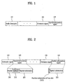
- an audio signal includes an audio descriptor 101, a downmix signal 103 and a spatial information signal 105.
- the audio signal may include ancillary data as well as the audio descriptor 101 and the downmix signal 103.
- the present invention may include the spatial information signal 105 as ancillary data.
- the audio signal may selectively include the audio descriptor 101.
- the audio descriptor 101 is comprised of small number of basic informations necessary for audio decoding such as a transmission rate of a transmitted audio signal, a number of channels, a sampling frequency of compressed data, an identifier indicating a currently used codec and the like.
- An audio signal decoding apparatus is able to know a type of a codec used by an audio signal using the audio descriptor 101.
- the audio signal decoding apparatus is able to know whether a received audio signal is the signal restoring a multi-channel using the spatial information signal 105 and the downmix signal 103.
- the multi-channel may include a virtual 3-dimensional surround as well as an actual multi-channel.
- an audio signal having the spatial information signal 105 and the downmix signal 103 combined together is made audible through one or two channels.
- the audio descriptor 101 is located independent from the downmix or the spatial information signal 103 or 105 included in the audio signal. For instance, the audio descriptor 101 is located within a separate field indicating an audio signal.
- the audio signal decoding apparatus is able to decode the downmix signal 103 using the audio descriptor 101.
- the downmix signal 103 is a signal generated from downmixing a multi-channel.
- the downmix signal 103 can be generated from a downmixing unit (not shown in the drawing) included in an audio signal encoding apparatus (not shown in the drawing) or generated artificially.
- the downmix signal 103 can be categorized into a case of including the spatial information signal 105 and a case of not including the header.
- the header is included in each frame by a frame unit.
- the downmix signal 103 does not include the header, as mentioned in the foregoing description, the downmix signal 103 can be decoded using the audio descriptor 101 by an audio signal decoding apparatus.
- the downmix signal 103 takes either a form of including the header for each frame or a form of not including the header. And, the downmix signal 103 is included in an audio signal in a same manner until contents end.
- the spatial information signal 105 is also categorized into a case of including the header and spatial information and a case of including the spatial information only without including the header.
- the header of the spatial information signal 105 differs from that of the downmix signal 103 in that it is unnecessary to be inserted in each frame identically.
- the spatial information signal 105 is able to use a frame including the header and a frame not including the header together.
- Most of information included in the header of the spatial information signal 105 is configuration information that decodes the spatial information by interpreting the spatial information.
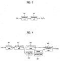
- FIG. 2 is a configurational diagram of an audio signal transferred to an audio signal decoding apparatus from an audio signal encoding apparatus according to another embodiment of the present invention.
- an audio signal includes the downmix signal 103 and the spatial information signal 105. And, the audio signal exists in an ES (elementary stream) form that frames are arranged.
- Each of the downmix signal 103 and the spatial information signal 105 is occasionally transferred as a separate ES form to an audio signal decoding apparatus. And the downmix signal 103 and the spatial information signal 105, as shown in FIG. 2 , can be combined into one ES form to be transferred to the audio signal decoding apparatus.
- the spatial information signal 105 can be included in a position of ancillary data (ancillary data) or additional data (extension data) of the downmix signal 103.
- the audio signal may include signal identification information indicating whether the spatial information signal 105 is combined with the downmix signal 103.
- a frame of the spatial information signal 105 can be categorized into a case of including the header 201 and the spatial information 203 and a case of including the spatial information 203 only.
- the spatial information signal 105 is able to use a frame including the header 201 and a frame not including the header 201 together.
- the header 201 is inserted in the spatial information signal 105 at least once.
- an audio signal encoding apparatus may insert the header 201 into each frame in the spatial information signal 105, periodically insert the header 201 into each fixed interval of frames in the spatial information signal 105 or non-periodically insert the header 201 into each random interval of frames in the spatial information signal 105.
- the audio signal may include information (hereinafter named 'header identification information') indicating whether the header 201 is included in a frame 201.
- the audio signal decoding apparatus extracts the configuration information 205 from the header 201 and then decodes the spatial information 203 transferred after (behind) the header 201 according to the configuration information 205. Since the header 201 is information for decoding by interpreting the spatial information 203, the header 201 is transferred in the early stage of transferring the audio signal.
- the audio signal decoding apparatus decodes the spatial information 203 using the header 201 transferred in the early stage.
- the audio signal decoding apparatus extracts the configuration information 205 from the header 201 different from the former header 201 firstly inserted in the audio signal and is then able to decode the audio signal using the extracted configuration information 205.
- the configuration information 205 extracted from the header 201 inserted in the audio signal may be identical to the former configuration information 205 extracted from the header 201 which had been transferred in the early stage or may not.
- the header 201 is variable, the configuration information 205 is extracted from a new header 201, the extracted configuration information 205 is decoded and the spatial information 203 transmitted behind the header 201 is then decoded. If the header 201 is invariable, it is decided whether the new header 201 is identical to the old header 201 that was previously transferred. If theses two headers 201 are different from each other, it can be detected that an error occurs in an audio signal on an audio signal transfer path.
- the configuration information 205 extracted from the header 201 of the spatial information signal 105 is the information to interpret the spatial information 203.
- the spatial information signal 105 is able to include information (hereinafter named ⁇ time align information') for discriminating a time delay difference between two signals in generating a multi-channel using the downmix signal 103 and the spatial information signal 105 by the audio signal decoding apparatus.
- ⁇ time align information' information for discriminating a time delay difference between two signals in generating a multi-channel using the downmix signal 103 and the spatial information signal 105 by the audio signal decoding apparatus.
- An audio signal transferred to the audio signal decoding apparatus from the audio signal encoding apparatus is parsed by a demultiplexing unit (not shown in the drawing) and is then separated into the downmix signal 103 and the spatial information signal 105.
- the downmix signal 103 separated by the demultiplexing unit is decoded.
- a decoded downmix signal 103 generates a multi-channel using the spatial information signal 105.
- the audio signal decoding apparatus is able to adjust synchronization between two signals, a position of a start point of combining two signals and the like using the time align information (not shown in the drawing) included in the configuration information 205 extracted from the header 201 of the spatial information signal 105.
- Position information 207 of a time slot to which a parameter will be applied is included in the spatial information 203 included in the spatial information signal 105.
- a spatial parameter spatial cue
- ICCs interchannel correlations
- CPCs channel prediction coefficients
- each spatial cue or a bundle of spatial cues will be called 'parameter'.
- N parameters exist in a frame included in the spatial information signal 105
- the N parameters are applied to specific time slot positions of frames, respectively. If information indicating a parameter will be applied to which one of time slots included in a frame is named the position information 207 of the time slot, the audio signal decoding apparatus decodes the spatial information 203 using the position information 207 of the time slot to which the parameter will be applied. In this case, the parameter is included in the spatial information 203.
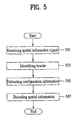
- FIG. 3 is a schematic block diagram of an apparatus for decoding an audio signal according to one embodiment of the present invention.
- an apparatus for decoding an audio signal includes a receiving unit 301 and an extracting unit 303.
- the receiving unit 301 of the audio signal decoding apparatus receives an audio signal transferred in an ES form by an audio signal encoding apparatus via an input terminal IN1.
- the audio signal received by the audio signal decoding apparatus includes an audio descriptor 101 and the downmix signal 103 and may further include the spatial information signal 105 as ancillary data (ancillary data) or additional data (extension data).
- ancillary data ancillary data
- additional data extension data
- the extracting unit 303 of the audio signal decoding apparatus extracts the configuration information 205 from the header 201 included in the received audio signal and then outputs the extracted configuration information 205 via an output terminal OUT1.
- the audio signal may include the header identification information for identifying whether the header 201 is included in a frame.
- the audio signal decoding apparatus identifies whether the header 201 is included in the frame using the header identification information included in the audio signal. If the header 201 is included, the audio signal decoding apparatus extracts the configuration information 205 from the header 201. In the present invention, at least one header 201 is included in the spatial information signal 105.
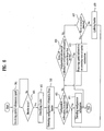
- FIG. 4 is a block diagram of an apparatus for decoding an audio signal according to another embodiment of the present invention.
- an apparatus for decoding an audio signal includes the receiving unit 301, the demultiplexing unit 401, a core decoding unit 403, a multi-channel generating unit 405, a spatial information decoding unit 407 and the extracting unit 303.
- the receiving unit 301 of the audio signal decoding apparatus receives an audio signal transferred in a bitstream form from an audio signal encoding apparatus via an input terminal IN2. And, the receiving unit 301 sends the received audio signal to the demultiplexing unit 401.
- the demultiplexing unit 401 separates the audio signal sent by the receiving unit 301 into an encoded downmix signal 103 and an encoded spatial information signal 105.
- the demultiplexing unit 401 transfers the encoded downmix signal 103 separated from a bitstream to the core decoding unit 403 and transfers the encoded spatial information signal 105 separated from the bitstream to the extracting unit 303.
- the encoded downmix signal 103 is decoded by the core decoding unit 403 and is then transferred to the multi-channel generating unit 405.
- the encoded spatial information signal 105 includes the header 201 and the spatial information 203.
- the extracting unit 303 extracts the configuration information 205 from the header 201.
- the extracting unit 303 is able to discriminate a presence of the header 201 using the header identification information included in the audio signal.
- the header identification information may represent whether the header 201 is included in a frame included in the spatial information signal 105.
- the header identification information may indicate an order of a frame or a bit sequence of the audio signal, in which the configuration information 205 extracted from the header 201 is included if the header 201 is included in the frame.
- the extracting unit 303 extracts the configuration information 205 from the header 201 included in the frame.
- the extracted configuration information 205 is then decoded.
- the spatial information decoding unit 407 decodes the spatial information 203 included in the frame according to decoded configuration information 205.
- the multi-channel generating unit 405 generates a multi-channel signal using the decoded downmix signal 103 and decoded spatial information 203 and then outputs the generated multi-channel signal via an output terminal OUT2.
- FIG. 5 is a flowchart of a method of decoding an audio signal according to one embodiment of the present invention.
- an audio signal decoding apparatus receives the spatial information signal 105 transferred in a bitstream form by an audio signal encoding apparatus (S501).
- the spatial information signal 105 can be categorized into a case of being transferred as an ES separated from the downmix signal 103 and a case of being transferred by being combined with the downmix signal 103.
- the demultiplexing unit 401 of an audio signal separates the received audio signal into the encoded downmix signal 103 and the encoded spatial information signal 105.
- the encoded spatial information signal 105 includes the header 201 and the spatial information 203. If the header 201 is included in a frame of the spatial information signal 105, the audio signal decoding apparatus identifies the header 201 (S503).
- the audio signal decoding apparatus extracts the configuration information 205 from the header 201 (S505).
- the audio signal decoding apparatus decodes the spatial information 203 using the extracted configuration information 205 (S507).
- FIG. 6 is a flowchart of a method of decoding an audio signal according to another embodiment of the present invention.
- an audio signal decoding apparatus receives the spatial information signal 105 transferred in a bitstream form by an audio signal encoding apparatus (S501).
- the spatial information signal 105 can be categorized into a case of being transferred as an ES separated from the downmix signal 103 and a case of being transferred by being included in ancillary data or extension data of the downmix signal 103.
- the demultiplexing unit 401 of an audio signal separates the received audio signal into the encoded downmix signal 103 and the encoded spatial information signal 105.
- the encoded spatial information signal 105 includes the header 201 and the spatial information 203.
- the audio signal decoding apparatus decides whether the header 201 is included in a frame (S601).
- the audio signal decoding apparatus identifies the header 201 (S503).
- the audio signal decoding apparatus then extracts the configuration information 205 from the header 201 (S505).
- the audio signal decoding apparatus decides whether the configuration information 205 extracted from the header 201 is the configuration information 205 extracted from a first header 201 included in the spatial information signal 105 (S603).
- the audio signal decoding apparatus decodes the configuration information 205 (S611) and decodes the spatial information 203 transferred behind the configuration information 205 according to the decoded configuration information 205.
- the audio signal decoding apparatus decides whether the configuration information 205 extracted from the header 201 is identical to the configuration information 205 extracted from the first header 201 (S605).
- the audio signal decoding apparatus decodes the spatial information 203 using the decoded configuration information 205 extracted from the first header 201.
- the audio signal decoding apparatus decides whether an error occurs in the audio signal on a transfer path from the audio signal encoding apparatus to the audio signal decoding apparatus (S607).
- the audio signal decoding apparatus updates the header 201 into the new header 201 (S609).
- the audio signal decoding apparatus then decodes the configuration information 205 extracted from the updated header 201 (S611).
- the audio signal decoding apparatus decodes the spatial information 203 transferred behind the configuration information 205 according to the decoded configuration information 205.
- the audio signal decoding apparatus removes the spatial information 203 included in the frame including the erroneous configuration information 205 or corrects the error of the spatial information 203 (S613).
- FIG. 7 is a flowchart of a method of decoding an audio signal according to a further embodiment of the present invention.
- an audio signal decoding apparatus receives the spatial information signal 105 transferred in a bitstream form by an audio signal encoding apparatus (S501).
- the demultiplexing unit 401 of an audio signal separates the received audio signal into the encoded downmix signal 103 and the encoded spatial information signal 105.
- the position information 207 of the time slot to which a parameter will be applied is included in the spatial information signal 105.
- the audio signal decoding apparatus extracts the position information 207 of the time slot from the spatial information 203 (S701).
- the audio signal decoding apparatus applies a parameter to the corresponding time slot by adjusting a position of the time slot, to which the parameter will be applied, using the extracted position information of the time slot (S703).
- FIG. 8 is a flowchart of a method of obtaining a position information representing quantity according to one embodiment of the present invention.
- a position information representing quantity of a time slot is the number of bits allocated to represent the position information 207 of the time slot.
- the position information representing quantity of the time slot, to which a first parameter is applied can be found by subtracting the number of parameters from the number of time slots, adding 1 to the subtraction result, taking a 2-base logarithm on the added value and applying a ceil function to the logarithm value.
- the position information representing quantity of the time slot, to which the first parameter will be applied can be found by ceil(log 2 (k-i+1)), where 'k' and ⁇ i' are the number of time slots and the number of parameters, respectively.
- the position information representing quantity of the time slot, to which an (N+1) th parameter will be applied is represented as the position information 207 of the time slot to which an N th parameter is applied.
- the position information 207 of the time slot, to which an N th parameter is applied can be found by adding the number of time slots existing between the time slot to which the N th parameter is applied and a time slot to which an (N-1) th parameter is applied to the position information of the time slot to which the (N-1) th parameter is applied and adding 1 to the added value (S801).
- the position information of the time slot to which the (N+1) th parameter will be applied can be found by j(N)+r(N+1)+1, where r(N+1) indicates the number of time slots existing between the time slot to which.the (N+1) th parameter is applied and the time slot to which the N th parameter is applied.
- the time slot position information representing quantity representing the position of the time slot to which the (N+1) th parameter is applied can be obtained.
- the time slot position information representing quantity representing the position of the time slot to which the (N+1) th parameter is applied can be found by subtracting the number of parameters applied to a frame and the position information of the time slot to which the N th parameter is applied from the number of time slots and adding (N+1) to the subtraction value (S803).
- the position information representing quantity of the time slot to which the (N+1) th parameter is applied can be found by ceil (log 2 (k-i+N+1-j(N))), where 'k', 'i' and 'j(N)' are the number of time slots, the number of parameters and the position information 205 ,of the time slot to which an N th parameter is applied, respectively.
- the position information representing quantity of the time slot to which the (N+1) th parameter is applied has the number of allocated bits inverse-proportional to ⁇ N'. Namely, the position information representing quantity of the time slot to which the parameter is applied is a variable value depending on ⁇ N'.
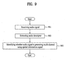
- FIG. 9 is a flowchart of a method of decoding an audio signal according to further embodiment of the present invention.
- An audio signal decoding apparatus receives an audio signal from an audio signal encoding apparatus (S901).
- the audio signal includes the audio descriptor 101, the downmix signal 103 and the spatial information signal 105.
- the audio signal decoding apparatus extracts the audio descriptor 101 included in the audio signal (S903).
- An identifier indicating an audio codec is included in the audio descriptor 101.
- the audio signal decoding apparatus recognizes that the audio signal includes the downmix signal 103 and the spatial information signal 105 using the audio descriptor 101.
- the audio signal decoding apparatus is able to discriminate that the transferred audio signal is a signal for generating a multi-channel, using the spatial information signal 105 (S905).
- the audio signal decoding apparatus converts the downmix signal 103 to a multi-channel signal using the spatial information signal 105.
- the header 201 can be included in the spatial information signal 105 each predetermined interval.
- a method and apparatus for decoding an audio signal according to the present invention can make a header selectively included in a spatial information signal.
- spatial information can be decoded even if the audio signal is reproduced from a random point by the audio signal decoding apparatus.
Abstract
Description
- The present invention relates to an audio signal processing, and more particularly, to an apparatus for encoding and decoding an audio signal and method thereof.
- Generally, an audio signal encoding apparatus compresses an audio signal into a mono or stereo type downmix signal instead of compressing each channels of a multi-channel audio signal. The audio signal encoding apparatus transfers the compressed downmix signal to a decoding apparatus together with a spatial information signal (or, ancillary data signal) or stores the compressed downmix signal and the spatial information signal in a storage medium.
- In this case, the spatial information signal, which is extracted in downmixing a multi-channel audio signal, is used in restoring an original multi-channel audio signal from a compressed downmix signal.
- The spatial information signal includes a header and spatial information. And, configuration information is included in the header. The header is the information for interpreting the spatial information.
- An audio signal decoding apparatus decodes the spatial information using the configuration information included in the header. The configuration information, which is included in the header, is transferred to a decoding apparatus or stored in a storage medium together with the spatial information.
- An audio signal encoding apparatus multiplexes an encoded downmix signal and the spatial information signal together into a bitstream form and then transfers the multiplexed signal to a decoding apparatus. Since configuration information is invariable in general, a header including configuration information is inserted in a bitstream once. Since configuration information is transmitted with being initially inserted in an audio signal once, an audio signal decoding apparatus has a problem in decoding spatial information due to non-existence of configuration information in case of reproducing the audio signal from a random timing point. Namely, since an audio signal is reproduced from a specific timing point requested by a user instead of being reproduced from an initial part in case of a broadcast, VOD (video on demand) or the like, it is unable to use configuration information transferred by being included in an audio signal. So, it may be unable to decode spatial information.
- "Der MPEG-2-Standard: Generische Codierung für Bewegtbilder und zugehörige Audio-Information, Audio-Codierung (Teil 4), Schröder EF et al, Fernseh -und kino-Technik, Vol. 48, no. 7/08, 30 August 1994, pages 364-368, 370-373, discloses the use of headers including spatial information that are incorporated in an enhancement multichannel layer.
- "Proposed changes in MPEG-4 BSAC multi-channel audio coding", Eunmi L. Oh et.al., ISO/IEC JTC1/SC29/WG11 MPEG2004/M11018, 19 July 2004, , may be construed to disclose a technique relating to BSAC multi-channel, involving syntax modifications that would enhance BSAC multi-channel providing backward compatibility.
- "Low complexity parametric stereo coding", Schuijers E. et.al., CONVENTION OF THE AUDIO ENGINEERING SOCIETY, 8 May 2004, , may be construed to disclose parametric stereo coding technique to efficiently code a stereo audio signal as a monaural signal plus a small amount of stereo parameters. The monaural signal can be encoded using any audio coder. The stereo parameters can be embedded in the ancillary part of the mono bit stream creating backwards mono compatibility. In the decoder, first the monaural signal is decoded after which the stereo signal is reconstructed from the stereo parameters.
- There are provided a method and an apparatus according to the independent claims.
- Developments are set forth in the dependent claims.
- An object of the present invention is to provide a method and apparatus for decoding an audio signal which enables the audio signal to be decoded even if the audio signal is reproduced from a random point by the audio signal decoding apparatus, by making header selectively included in a frame in the spatial information signal.
- Preferably, a method of decoding an audio signal includes receiving an audio signal including an audio descriptor, recognizing that the audio signal includes a downmix signal and a spatial information signal using the audio descriptor, and converting the downmix signal to a multi-channel signal using the spatial information signal, wherein the spatial information signal includes a header each a preset temporal or spatial interval.
-
-
FIG. 1 is a configurational diagram of an audio signal according to one embodiment of the present invention. -
FIG. 2 is a configurational diagram of an audio signal according to another embodiment of the present invention. -
FIG. 3 is a block diagram of an apparatus for decoding an audio signal according to one embodiment of the present invention. -
FIG. 4 is a block diagram of an apparatus for decoding an audio signal according to another embodiment of the present invention. -
FIG. 5 is a flowchart of a method of decoding an audio signal according to one embodiment of the present invention. -
FIG. 6 is a flowchart of a method of decoding an audio signal according to another embodiment of the present invention. -
FIG. 7 is a flowchart of a method of decoding an audio signal according to a further embodiment of the present invention. -
FIG. 8 is a flowchart of a method of obtaining a position information representing quantity according to one embodiment of the present invention. -
FIG. 9 is a flowchart of a method of decoding an audio signal according to another further embodiment of the present invention. - Reference will now be made in detail to the preferred embodiments of the present invention, examples of which are illustrated in the accompanying drawings.
- For understanding of the present invention, an apparatus and method of encoding an audio signal is explained prior to an apparatus and method of decoding an audio signal. Yet, the decoding apparatus and method according to the present invention are not limited to the following encoding apparatus and method. And, the present invention is applicable to an audio coding scheme for generating a multi-channel using spatial information as well as MP3 (MPEG 1/2-layer III) and AAC (advanced audio coding).
-
FIG. 1 is a configurational diagram of an audio signal transferred to an audio signal decoding apparatus from an audio signal encoding apparatus according to one embodiment of the present invention. - Referring to
FIG. 1 , an audio signal includes anaudio descriptor 101, adownmix signal 103 and aspatial information signal 105. - In case of using a coding scheme for reproducing an audio signal for broadcasting or the like, the audio signal may include ancillary data as well as the
audio descriptor 101 and thedownmix signal 103. The present invention may include thespatial information signal 105 as ancillary data. In order for an audio signal decoding apparatus to know basic information of audio codec without analyzing an audio signal, the audio signal may selectively include theaudio descriptor 101. Theaudio descriptor 101 is comprised of small number of basic informations necessary for audio decoding such as a transmission rate of a transmitted audio signal, a number of channels, a sampling frequency of compressed data, an identifier indicating a currently used codec and the like. - An audio signal decoding apparatus is able to know a type of a codec used by an audio signal using the
audio descriptor 101. In particular, using theaudio descriptor 101, the audio signal decoding apparatus is able to know whether a received audio signal is the signal restoring a multi-channel using thespatial information signal 105 and thedownmix signal 103. In this case, the multi-channel may include a virtual 3-dimensional surround as well as an actual multi-channel. By the virtual 3-dimensional surround technology, an audio signal having thespatial information signal 105 and thedownmix signal 103 combined together is made audible through one or two channels. - The
audio descriptor 101 is located independent from the downmix or thespatial information signal audio descriptor 101 is located within a separate field indicating an audio signal. - In case that a header is not provided to the
downmix signal 103, the audio signal decoding apparatus is able to decode thedownmix signal 103 using theaudio descriptor 101. - The
downmix signal 103 is a signal generated from downmixing a multi-channel. Thedownmix signal 103 can be generated from a downmixing unit (not shown in the drawing) included in an audio signal encoding apparatus (not shown in the drawing) or generated artificially. - The
downmix signal 103 can be categorized into a case of including thespatial information signal 105 and a case of not including the header. - In case that the
downmix signal 103 includes the header, the header is included in each frame by a frame unit. In case that thedownmix signal 103 does not include the header, as mentioned in the foregoing description, thedownmix signal 103 can be decoded using theaudio descriptor 101 by an audio signal decoding apparatus. Thedownmix signal 103 takes either a form of including the header for each frame or a form of not including the header. And, thedownmix signal 103 is included in an audio signal in a same manner until contents end. - The
spatial information signal 105 is also categorized into a case of including the header and spatial information and a case of including the spatial information only without including the header. The header of thespatial information signal 105 differs from that of thedownmix signal 103 in that it is unnecessary to be inserted in each frame identically. In particular, thespatial information signal 105 is able to use a frame including the header and a frame not including the header together. Most of information included in the header of thespatial information signal 105 is configuration information that decodes the spatial information by interpreting the spatial information. -
FIG. 2 is a configurational diagram of an audio signal transferred to an audio signal decoding apparatus from an audio signal encoding apparatus according to another embodiment of the present invention. - Referring to
FIG. 2 , an audio signal includes thedownmix signal 103 and thespatial information signal 105. And, the audio signal exists in an ES (elementary stream) form that frames are arranged. - Each of the
downmix signal 103 and thespatial information signal 105 is occasionally transferred as a separate ES form to an audio signal decoding apparatus. And thedownmix signal 103 and thespatial information signal 105, as shown inFIG. 2 , can be combined into one ES form to be transferred to the audio signal decoding apparatus. - In case that the
downmix signal 103 and thespatial information signal 105, which are combined into one ES form, are transferred to the audio signal decoding apparatus, the spatial information signal 105 can be included in a position of ancillary data (ancillary data) or additional data (extension data) of thedownmix signal 103. - And, the audio signal may include signal identification information indicating whether the
spatial information signal 105 is combined with thedownmix signal 103. - A frame of the spatial information signal 105 can be categorized into a case of including the
header 201 and thespatial information 203 and a case of including thespatial information 203 only. In particular, thespatial information signal 105 is able to use a frame including theheader 201 and a frame not including theheader 201 together. - In the present invention, the
header 201 is inserted in the spatial information signal 105 at least once. In particular, an audio signal encoding apparatus may insert theheader 201 into each frame in thespatial information signal 105, periodically insert theheader 201 into each fixed interval of frames in the spatial information signal 105 or non-periodically insert theheader 201 into each random interval of frames in thespatial information signal 105. - The audio signal may include information (hereinafter named 'header identification information') indicating whether the
header 201 is included in aframe 201. - In case that the
header 201 is included in thespatial information signal 105, the audio signal decoding apparatus extracts theconfiguration information 205 from theheader 201 and then decodes thespatial information 203 transferred after (behind) theheader 201 according to theconfiguration information 205. Since theheader 201 is information for decoding by interpreting thespatial information 203, theheader 201 is transferred in the early stage of transferring the audio signal. - In case that the
header 201 is not included in thespatial information signal 105, the audio signal decoding apparatus decodes thespatial information 203 using theheader 201 transferred in the early stage. - In case that the
header 201 is lost while the audio signal is transferred to the audio signal decoding apparatus from the audio signal encoding apparatus or in case that the audio signal transferred in a streaming format is decoded from its middle part to be used for broadcasting or the like, it is unable to use theheader 201 that was previously transferred. In this case, the audio signal decoding apparatus extracts theconfiguration information 205 from theheader 201 different from theformer header 201 firstly inserted in the audio signal and is then able to decode the audio signal using the extractedconfiguration information 205. In this case, theconfiguration information 205 extracted from theheader 201 inserted in the audio signal may be identical to theformer configuration information 205 extracted from theheader 201 which had been transferred in the early stage or may not. - If the
header 201 is variable, theconfiguration information 205 is extracted from anew header 201, the extractedconfiguration information 205 is decoded and thespatial information 203 transmitted behind theheader 201 is then decoded. If theheader 201 is invariable, it is decided whether thenew header 201 is identical to theold header 201 that was previously transferred. If theses twoheaders 201 are different from each other, it can be detected that an error occurs in an audio signal on an audio signal transfer path. - The
configuration information 205 extracted from theheader 201 of thespatial information signal 105 is the information to interpret thespatial information 203. - The
spatial information signal 105 is able to include information (hereinafter named `time align information') for discriminating a time delay difference between two signals in generating a multi-channel using thedownmix signal 103 and the spatial information signal 105 by the audio signal decoding apparatus. - An audio signal transferred to the audio signal decoding apparatus from the audio signal encoding apparatus is parsed by a demultiplexing unit (not shown in the drawing) and is then separated into the
downmix signal 103 and thespatial information signal 105. - The
downmix signal 103 separated by the demultiplexing unit is decoded. A decodeddownmix signal 103 generates a multi-channel using thespatial information signal 105. In generating the multi-channel by combining thedownmix signal 103 and thespatial information signal 105, the audio signal decoding apparatus is able to adjust synchronization between two signals, a position of a start point of combining two signals and the like using the time align information (not shown in the drawing) included in theconfiguration information 205 extracted from theheader 201 of thespatial information signal 105. -
Position information 207 of a time slot to which a parameter will be applied is included in thespatial information 203 included in thespatial information signal 105. As a spatial parameter (spatial cue), there is CLDs (channel level differences) indicating an energy difference between audio signals, ICCs (interchannel correlations) indicating closeness or similarity between audio signals, CPCs (channel prediction coefficients) indicating a coefficient predicting an audio signal value using other signals. Hereinafter, each spatial cue or a bundle of spatial cues will be called 'parameter'. - In case N parameters exist in a frame included in the
spatial information signal 105, the N parameters are applied to specific time slot positions of frames, respectively. If information indicating a parameter will be applied to which one of time slots included in a frame is named theposition information 207 of the time slot, the audio signal decoding apparatus decodes thespatial information 203 using theposition information 207 of the time slot to which the parameter will be applied. In this case, the parameter is included in thespatial information 203. -
FIG. 3 is a schematic block diagram of an apparatus for decoding an audio signal according to one embodiment of the present invention. - Referring to
FIG. 3 , an apparatus for decoding an audio signal according to one embodiment of the present invention includes a receivingunit 301 and an extractingunit 303. - The receiving
unit 301 of the audio signal decoding apparatus receives an audio signal transferred in an ES form by an audio signal encoding apparatus via an input terminal IN1. - The audio signal received by the audio signal decoding apparatus includes an
audio descriptor 101 and thedownmix signal 103 and may further include the spatial information signal 105 as ancillary data (ancillary data) or additional data (extension data). - The extracting
unit 303 of the audio signal decoding apparatus extracts theconfiguration information 205 from theheader 201 included in the received audio signal and then outputs the extractedconfiguration information 205 via an output terminal OUT1. - The audio signal may include the header identification information for identifying whether the
header 201 is included in a frame. - The audio signal decoding apparatus identifies whether the
header 201 is included in the frame using the header identification information included in the audio signal. If theheader 201 is included, the audio signal decoding apparatus extracts theconfiguration information 205 from theheader 201. In the present invention, at least oneheader 201 is included in thespatial information signal 105. -
FIG. 4 is a block diagram of an apparatus for decoding an audio signal according to another embodiment of the present invention. - Referring to
FIG. 4 , an apparatus for decoding an audio signal according to another embodiment of the present invention includes the receivingunit 301, thedemultiplexing unit 401, acore decoding unit 403, amulti-channel generating unit 405, a spatialinformation decoding unit 407 and the extractingunit 303. - The receiving
unit 301 of the audio signal decoding apparatus receives an audio signal transferred in a bitstream form from an audio signal encoding apparatus via an input terminal IN2. And, the receivingunit 301 sends the received audio signal to thedemultiplexing unit 401. - The
demultiplexing unit 401 separates the audio signal sent by the receivingunit 301 into an encodeddownmix signal 103 and an encodedspatial information signal 105. Thedemultiplexing unit 401 transfers the encodeddownmix signal 103 separated from a bitstream to thecore decoding unit 403 and transfers the encoded spatial information signal 105 separated from the bitstream to the extractingunit 303. - The encoded
downmix signal 103 is decoded by thecore decoding unit 403 and is then transferred to themulti-channel generating unit 405. The encodedspatial information signal 105 includes theheader 201 and thespatial information 203. - If the
header 201 is included in the encodedspatial information signal 105, the extractingunit 303 extracts theconfiguration information 205 from theheader 201. The extractingunit 303 is able to discriminate a presence of theheader 201 using the header identification information included in the audio signal. In particular, the header identification information may represent whether theheader 201 is included in a frame included in thespatial information signal 105. The header identification information may indicate an order of a frame or a bit sequence of the audio signal, in which theconfiguration information 205 extracted from theheader 201 is included if theheader 201 is included in the frame. - In case of deciding that the
header 201 is included in the frame via the header identification information, the extractingunit 303 extracts theconfiguration information 205 from theheader 201 included in the frame. The extractedconfiguration information 205 is then decoded. - The spatial
information decoding unit 407 decodes thespatial information 203 included in the frame according to decodedconfiguration information 205. - And, the
multi-channel generating unit 405 generates a multi-channel signal using the decodeddownmix signal 103 and decodedspatial information 203 and then outputs the generated multi-channel signal via an output terminal OUT2. -
FIG. 5 is a flowchart of a method of decoding an audio signal according to one embodiment of the present invention. - Referring to
FIG. 5 , an audio signal decoding apparatus receives the spatial information signal 105 transferred in a bitstream form by an audio signal encoding apparatus (S501). - As mentioned in the foregoing description, the spatial information signal 105 can be categorized into a case of being transferred as an ES separated from the
downmix signal 103 and a case of being transferred by being combined with thedownmix signal 103. - The
demultiplexing unit 401 of an audio signal separates the received audio signal into the encodeddownmix signal 103 and the encodedspatial information signal 105. The encodedspatial information signal 105 includes theheader 201 and thespatial information 203. If theheader 201 is included in a frame of thespatial information signal 105, the audio signal decoding apparatus identifies the header 201 (S503). - The audio signal decoding apparatus extracts the
configuration information 205 from the header 201 (S505). - And, the audio signal decoding apparatus decodes the
spatial information 203 using the extracted configuration information 205 (S507). -
FIG. 6 is a flowchart of a method of decoding an audio signal according to another embodiment of the present invention. - Referring to
FIG. 6 , an audio signal decoding apparatus receives the spatial information signal 105 transferred in a bitstream form by an audio signal encoding apparatus (S501). - As mentioned in the foregoing description, the spatial information signal 105 can be categorized into a case of being transferred as an ES separated from the
downmix signal 103 and a case of being transferred by being included in ancillary data or extension data of thedownmix signal 103. - The
demultiplexing unit 401 of an audio signal separates the received audio signal into the encodeddownmix signal 103 and the encodedspatial information signal 105. The encodedspatial information signal 105 includes theheader 201 and thespatial information 203. The audio signal decoding apparatus decides whether theheader 201 is included in a frame (S601). - If the
header 201 is included in the frame, the audio signal decoding apparatus identifies the header 201 (S503). - The audio signal decoding apparatus then extracts the
configuration information 205 from the header 201 (S505). - The audio signal decoding apparatus decides whether the
configuration information 205 extracted from theheader 201 is theconfiguration information 205 extracted from afirst header 201 included in the spatial information signal 105 (S603). - If the
configuration information 205 is extracted from theheader 201 extracted first from the audio signal, the audio signal decoding apparatus decodes the configuration information 205 (S611) and decodes thespatial information 203 transferred behind theconfiguration information 205 according to the decodedconfiguration information 205. - If the
header 201 extracted from the audio signal is not theheader 201 extracted first from thespatial information signal 105, the audio signal decoding apparatus decides whether theconfiguration information 205 extracted from theheader 201 is identical to theconfiguration information 205 extracted from the first header 201 (S605). - If the
configuration information 205 is identical to theconfiguration information 205 extracted from thefirst header 201, the audio signal decoding apparatus decodes thespatial information 203 using the decodedconfiguration information 205 extracted from thefirst header 201. - If the extracted
configuration information 205 is not identical to theconfiguration information 205 extracted from thefirst header 201, the audio signal decoding apparatus decides whether an error occurs in the audio signal on a transfer path from the audio signal encoding apparatus to the audio signal decoding apparatus (S607). - If the
configuration information 205 is variable, the error does not occur even if theconfiguration information 205 is not identical to theconfiguration information 205 extracted from thefirst header 201. Hence, the audio signal decoding apparatus updates theheader 201 into the new header 201 (S609). The audio signal decoding apparatus then decodes theconfiguration information 205 extracted from the updated header 201 (S611). - The audio signal decoding apparatus decodes the
spatial information 203 transferred behind theconfiguration information 205 according to the decodedconfiguration information 205. - If the
configuration information 205, which is invariable, is not identical to theconfiguration information 205 extracted from thefirst header 201, it means that the error occurs on the audio signal transfer path. Hence, the audio signal decoding apparatus removes thespatial information 203 included in the frame including theerroneous configuration information 205 or corrects the error of the spatial information 203 (S613). -
FIG. 7 is a flowchart of a method of decoding an audio signal according to a further embodiment of the present invention. - Referring to
FIG. 7 , an audio signal decoding apparatus receives the spatial information signal 105 transferred in a bitstream form by an audio signal encoding apparatus (S501). - The
demultiplexing unit 401 of an audio signal separates the received audio signal into the encodeddownmix signal 103 and the encodedspatial information signal 105. In this case, theposition information 207 of the time slot to which a parameter will be applied is included in thespatial information signal 105. - The audio signal decoding apparatus extracts the
position information 207 of the time slot from the spatial information 203 (S701). - The audio signal decoding apparatus applies a parameter to the corresponding time slot by adjusting a position of the time slot, to which the parameter will be applied, using the extracted position information of the time slot (S703).
-
FIG. 8 is a flowchart of a method of obtaining a position information representing quantity according to one embodiment of the present invention. A position information representing quantity of a time slot is the number of bits allocated to represent theposition information 207 of the time slot. - The position information representing quantity of the time slot, to which a first parameter is applied, can be found by subtracting the number of parameters from the number of time slots, adding 1 to the subtraction result, taking a 2-base logarithm on the added value and applying a ceil function to the logarithm value. In particular, the position information representing quantity of the time slot, to which the first parameter will be applied, can be found by ceil(log2(k-i+1)), where 'k' and `i' are the number of time slots and the number of parameters, respectively.
- Assuming that `N' is a natural number, the position information representing quantity of the time slot, to which an (N+1)th parameter will be applied, is represented as the
position information 207 of the time slot to which an Nth parameter is applied. In this case, theposition information 207 of the time slot, to which an Nth parameter is applied, can be found by adding the number of time slots existing between the time slot to which the Nth parameter is applied and a time slot to which an (N-1)th parameter is applied to the position information of the time slot to which the (N-1)th parameter is applied and adding 1 to the added value (S801). In particular, the position information of the time slot to which the (N+1)th parameter will be applied can be found by j(N)+r(N+1)+1, where r(N+1) indicates the number of time slots existing between the time slot to which.the (N+1)th parameter is applied and the time slot to which the Nth parameter is applied. - If the
position information 207 of the time slot to which the Nth parameter is applied is found, the time slot position information representing quantity representing the position of the time slot to which the (N+1)th parameter is applied can be obtained. In particular, the time slot position information representing quantity representing the position of the time slot to which the (N+1)th parameter is applied can be found by subtracting the number of parameters applied to a frame and the position information of the time slot to which the Nth parameter is applied from the number of time slots and adding (N+1) to the subtraction value (S803). In particular, the position information representing quantity of the time slot to which the (N+1)th parameter is applied can be found by ceil (log2(k-i+N+1-j(N))), where 'k', 'i' and 'j(N)' are the number of time slots, the number of parameters and theposition information 205 ,of the time slot to which an Nth parameter is applied, respectively. - In case of obtaining the position information representing quantity of the time slot in the above-explained manner, the position information representing quantity of the time slot to which the (N+1)th parameter is applied has the number of allocated bits inverse-proportional to `N'. Namely, the position information representing quantity of the time slot to which the parameter is applied is a variable value depending on `N'.
-
FIG. 9 is a flowchart of a method of decoding an audio signal according to further embodiment of the present invention. - An audio signal decoding apparatus receives an audio signal from an audio signal encoding apparatus (S901). The audio signal includes the
audio descriptor 101, thedownmix signal 103 and thespatial information signal 105. - The audio signal decoding apparatus extracts the
audio descriptor 101 included in the audio signal (S903). An identifier indicating an audio codec is included in theaudio descriptor 101. - The audio signal decoding apparatus recognizes that the audio signal includes the
downmix signal 103 and the spatial information signal 105 using theaudio descriptor 101. In particular, the audio signal decoding apparatus is able to discriminate that the transferred audio signal is a signal for generating a multi-channel, using the spatial information signal 105 (S905). - And, the audio signal decoding apparatus converts the
downmix signal 103 to a multi-channel signal using thespatial information signal 105. As mentioned in the foregoing description, theheader 201 can be included in the spatial information signal 105 each predetermined interval. - As mentioned in the foregoing description, a method and apparatus for decoding an audio signal according to the present invention can make a header selectively included in a spatial information signal.
- And, in case that a plurality of headers are included in the spatial information signal, spatial information can be decoded even if the audio signal is reproduced from a random point by the audio signal decoding apparatus.
- While the present invention has been described and illustrated herein with reference to the preferred embodiments thereof, it will be apparent to those skilled in the art that various modifications and variations can be made therein without departing from the scope of the invention. Thus, it is intended that the present invention covers the modifications and variations of this invention that come within the scope of the appended claims.
Claims (4)
- A method of decoding an audio signal, comprising:receiving (S501) an audio signal including a downmix signal, a spatial information signal categorized into a case of including a header and spatial information and a case of including the spatial information only without the header, and an audio descriptor,recognizing that the audio signal includes the downmix signal and the spatial information signal using the audio descriptor; andobtaining (S503), from the audio signal, header identification information indicating whether a frame of the spatial information signal includes the header or not;if the header identification information indicates that the frame of the spatial information signal includes the header;- extracting (S505) configuration information from the header, wherein at least a time align information is included in the configuration information;- decoding (S507) the spatial information from the spatial information signal using the extracted configuration information;- discriminating a time delay difference between two signals in generating a multichannel signal using the downmix signal and the spatial information signal based on the time align information included in the extracted configuration information; and- converting the downmix signal to the multi-channel signal using the configuration information and the spatial information.
- The method of claim 1, wherein the spatial information signal further includes position information of a time slot.
- The method of claim 2, further comprising:applying (S703) a parameter included in the spatial information signal to a corresponding time slot using position information of the corresponding time slot included in the spatial information signal.
- An apparatus adapted to perform the method according to any one of claims 1 to 3.
Applications Claiming Priority (15)
| Application Number | Priority Date | Filing Date | Title |
|---|---|---|---|
| US69500705P | 2005-06-30 | 2005-06-30 | |
| US71211905P | 2005-08-30 | 2005-08-30 | |
| US71920205P | 2005-09-22 | 2005-09-22 | |
| US72300705P | 2005-10-04 | 2005-10-04 | |
| US72622805P | 2005-10-14 | 2005-10-14 | |
| US72922505P | 2005-10-24 | 2005-10-24 | |
| US73562805P | 2005-11-12 | 2005-11-12 | |
| KR20060004055 | 2006-01-13 | ||
| KR20060004065 | 2006-01-13 | ||
| KR20060004056 | 2006-01-13 | ||
| US78674006P | 2006-03-29 | 2006-03-29 | |
| US79232906P | 2006-04-17 | 2006-04-17 | |
| US80382506P | 2006-06-02 | 2006-06-02 | |
| KR1020060056480A KR20070003574A (en) | 2005-06-30 | 2006-06-22 | Method and apparatus for encoding and decoding an audio signal |
| PCT/KR2006/002583 WO2007004833A2 (en) | 2005-06-30 | 2006-06-30 | Method and apparatus for encoding and decoding an audio signal |
Publications (2)
| Publication Number | Publication Date |
|---|---|
| EP1908057A2 EP1908057A2 (en) | 2008-04-09 |
| EP1908057B1 true EP1908057B1 (en) | 2012-06-20 |
Family
ID=37604659
Family Applications (2)
| Application Number | Title | Priority Date | Filing Date |
|---|---|---|---|
| EP06757754A Active EP1913578B1 (en) | 2005-06-30 | 2006-06-30 | Method and apparatus for decoding an audio signal |
| EP06757755A Active EP1908057B1 (en) | 2005-06-30 | 2006-06-30 | Method and apparatus for decoding an audio signal |
Family Applications Before (1)
| Application Number | Title | Priority Date | Filing Date |
|---|---|---|---|
| EP06757754A Active EP1913578B1 (en) | 2005-06-30 | 2006-06-30 | Method and apparatus for decoding an audio signal |
Country Status (7)
| Country | Link |
|---|---|
| US (2) | US8185403B2 (en) |
| EP (2) | EP1913578B1 (en) |
| JP (1) | JP5006315B2 (en) |
| AU (1) | AU2006266579B2 (en) |
| CA (1) | CA2613885C (en) |
| MX (1) | MX2008000122A (en) |
| WO (2) | WO2007004833A2 (en) |
Families Citing this family (32)
| Publication number | Priority date | Publication date | Assignee | Title |
|---|---|---|---|---|
| EP1691348A1 (en) * | 2005-02-14 | 2006-08-16 | Ecole Polytechnique Federale De Lausanne | Parametric joint-coding of audio sources |
| EP1899958B1 (en) * | 2005-05-26 | 2013-08-07 | LG Electronics Inc. | Method and apparatus for decoding an audio signal |
| JP4988717B2 (en) | 2005-05-26 | 2012-08-01 | エルジー エレクトロニクス インコーポレイティド | Audio signal decoding method and apparatus |
| US8185403B2 (en) * | 2005-06-30 | 2012-05-22 | Lg Electronics Inc. | Method and apparatus for encoding and decoding an audio signal |
| US20070055510A1 (en) * | 2005-07-19 | 2007-03-08 | Johannes Hilpert | Concept for bridging the gap between parametric multi-channel audio coding and matrixed-surround multi-channel coding |
| EP1974346B1 (en) * | 2006-01-19 | 2013-10-02 | LG Electronics, Inc. | Method and apparatus for processing a media signal |
| WO2007091843A1 (en) * | 2006-02-07 | 2007-08-16 | Lg Electronics Inc. | Apparatus and method for encoding/decoding signal |
| CN102768836B (en) * | 2006-09-29 | 2014-11-05 | 韩国电子通信研究院 | Apparatus and method for coding and decoding multi-object audio signal with various channel |
| CN101529504B (en) * | 2006-10-16 | 2012-08-22 | 弗劳恩霍夫应用研究促进协会 | Apparatus and method for multi-channel parameter transformation |
| ATE503245T1 (en) * | 2006-10-16 | 2011-04-15 | Dolby Sweden Ab | ADVANCED CODING AND PARAMETER REPRESENTATION OF MULTI-CHANNEL DOWN-MIXED OBJECT CODING |
| KR100942142B1 (en) | 2007-10-11 | 2010-02-16 | 한국전자통신연구원 | Method and apparatus for transmitting and receiving of the object based audio contents |
| KR101461685B1 (en) * | 2008-03-31 | 2014-11-19 | 한국전자통신연구원 | Method and apparatus for generating side information bitstream of multi object audio signal |
| KR20090110242A (en) * | 2008-04-17 | 2009-10-21 | 삼성전자주식회사 | Method and apparatus for processing audio signal |
| US8903488B2 (en) | 2009-05-28 | 2014-12-02 | Angiodynamics, Inc. | System and method for synchronizing energy delivery to the cardiac rhythm |
| US9895189B2 (en) | 2009-06-19 | 2018-02-20 | Angiodynamics, Inc. | Methods of sterilization and treating infection using irreversible electroporation |
| CN102484547A (en) * | 2009-09-01 | 2012-05-30 | 松下电器产业株式会社 | Digital broadcasting transmission device, digital broadcasting reception device, digital broadcasting reception system |
| EP3739577B1 (en) | 2010-04-09 | 2022-11-23 | Dolby International AB | Mdct-based complex prediction stereo coding |
| WO2012051433A2 (en) | 2010-10-13 | 2012-04-19 | Angiodynamics, Inc. | System and method for electrically ablating tissue of a patient |
| KR20120071072A (en) * | 2010-12-22 | 2012-07-02 | 한국전자통신연구원 | Broadcastiong transmitting and reproducing apparatus and method for providing the object audio |
| US8787454B1 (en) | 2011-07-13 | 2014-07-22 | Google Inc. | Method and apparatus for data compression using content-based features |
| US9078665B2 (en) | 2011-09-28 | 2015-07-14 | Angiodynamics, Inc. | Multiple treatment zone ablation probe |
| US9966080B2 (en) * | 2011-11-01 | 2018-05-08 | Koninklijke Philips N.V. | Audio object encoding and decoding |
| TWI517142B (en) | 2012-07-02 | 2016-01-11 | Sony Corp | Audio decoding apparatus and method, audio coding apparatus and method, and program |
| US9437198B2 (en) | 2012-07-02 | 2016-09-06 | Sony Corporation | Decoding device, decoding method, encoding device, encoding method, and program |
| BR112014004128A2 (en) | 2012-07-02 | 2017-03-21 | Sony Corp | device and decoding method, device and encoding method, and, program |
| EP2741285B1 (en) * | 2012-07-02 | 2019-04-10 | Sony Corporation | Decoding device and method, encoding device and method, and program |
| KR20140046980A (en) | 2012-10-11 | 2014-04-21 | 한국전자통신연구원 | Apparatus and method for generating audio data, apparatus and method for playing audio data |
| EP2790419A1 (en) * | 2013-04-12 | 2014-10-15 | Fraunhofer-Gesellschaft zur Förderung der angewandten Forschung e.V. | Apparatus and method for center signal scaling and stereophonic enhancement based on a signal-to-downmix ratio |
| US9774974B2 (en) | 2014-09-24 | 2017-09-26 | Electronics And Telecommunications Research Institute | Audio metadata providing apparatus and method, and multichannel audio data playback apparatus and method to support dynamic format conversion |
| EP3067885A1 (en) | 2015-03-09 | 2016-09-14 | Fraunhofer-Gesellschaft zur Förderung der angewandten Forschung e.V. | Apparatus and method for encoding or decoding a multi-channel signal |
| US10905492B2 (en) | 2016-11-17 | 2021-02-02 | Angiodynamics, Inc. | Techniques for irreversible electroporation using a single-pole tine-style internal device communicating with an external surface electrode |
| WO2018164681A1 (en) * | 2017-03-08 | 2018-09-13 | Hewlett-Packard Development Company, L.P. | Combined audio signal output |
Family Cites Families (192)
| Publication number | Priority date | Publication date | Assignee | Title |
|---|---|---|---|---|
| US4016886A (en) * | 1974-11-26 | 1977-04-12 | The United States Of America As Represented By The United States Energy Research And Development Administration | Method for localizing heating in tumor tissue |
| DE2800039C2 (en) * | 1978-01-02 | 1984-06-20 | Horst Dr.Med. 6700 Ludwigshafen Kief | Acupuncture device |
| JPS6096079A (en) | 1983-10-31 | 1985-05-29 | Matsushita Electric Ind Co Ltd | Encoding method of multivalue picture |
| GB8408529D0 (en) * | 1984-04-03 | 1984-05-16 | Health Lab Service Board | Concentration of biological particles |
| US4661862A (en) * | 1984-04-27 | 1987-04-28 | Rca Corporation | Differential PCM video transmission system employing horizontally offset five pixel groups and delta signals having plural non-linear encoding functions |
| US4621862A (en) | 1984-10-22 | 1986-11-11 | The Coca-Cola Company | Closing means for trucks |
| JPS6294090A (en) | 1985-10-21 | 1987-04-30 | Hitachi Ltd | Encoding device |
| US4725885A (en) | 1986-12-22 | 1988-02-16 | International Business Machines Corporation | Adaptive graylevel image compression system |
| US5098843A (en) * | 1987-06-04 | 1992-03-24 | Calvin Noel M | Apparatus for the high efficiency transformation of living cells |
| JPH0793584B2 (en) | 1987-09-25 | 1995-10-09 | 株式会社日立製作所 | Encoder |
| DE68925030T2 (en) * | 1988-01-21 | 1996-07-25 | Massachusetts Inst Technology | MOLECULE TRANSPORT THROUGH FABRICS WITH THE USE OF ELECTROPORATION. |
| US5389069A (en) * | 1988-01-21 | 1995-02-14 | Massachusetts Institute Of Technology | Method and apparatus for in vivo electroporation of remote cells and tissue |
| EP0346513A1 (en) * | 1988-06-15 | 1989-12-20 | Etama Ag | Assembly for electrotherapy |
| NL8901032A (en) | 1988-11-10 | 1990-06-01 | Philips Nv | CODER FOR INCLUDING ADDITIONAL INFORMATION IN A DIGITAL AUDIO SIGNAL WITH A PREFERRED FORMAT, A DECODER FOR DERIVING THIS ADDITIONAL INFORMATION FROM THIS DIGITAL SIGNAL, AN APPARATUS FOR RECORDING A DIGITAL SIGNAL ON A CODE OF RECORD. OBTAINED A RECORD CARRIER WITH THIS DEVICE. |
| US5243686A (en) * | 1988-12-09 | 1993-09-07 | Oki Electric Industry Co., Ltd. | Multi-stage linear predictive analysis method for feature extraction from acoustic signals |
| DE69032624T2 (en) | 1989-01-27 | 1999-03-25 | Dolby Lab Licensing Corp | Formatting a coded signal for encoders and decoders of a high quality audio system |
| DE3912605B4 (en) * | 1989-04-17 | 2008-09-04 | Fraunhofer-Gesellschaft zur Förderung der angewandten Forschung e.V. | Digital coding method |
| US6289308B1 (en) * | 1990-06-01 | 2001-09-11 | U.S. Philips Corporation | Encoded wideband digital transmission signal and record carrier recorded with such a signal |
| NL9000338A (en) | 1989-06-02 | 1991-01-02 | Koninkl Philips Electronics Nv | DIGITAL TRANSMISSION SYSTEM, TRANSMITTER AND RECEIVER FOR USE IN THE TRANSMISSION SYSTEM AND RECORD CARRIED OUT WITH THE TRANSMITTER IN THE FORM OF A RECORDING DEVICE. |
| GB8921320D0 (en) | 1989-09-21 | 1989-11-08 | British Broadcasting Corp | Digital video coding |
| US5193537A (en) * | 1990-06-12 | 1993-03-16 | Zmd Corporation | Method and apparatus for transcutaneous electrical cardiac pacing |
| DE69210689T2 (en) * | 1991-01-08 | 1996-11-21 | Dolby Lab Licensing Corp | ENCODER / DECODER FOR MULTI-DIMENSIONAL SOUND FIELDS |
| US5173158A (en) * | 1991-07-22 | 1992-12-22 | Schmukler Robert E | Apparatus and methods for electroporation and electrofusion |
| ES2164640T3 (en) * | 1991-08-02 | 2002-03-01 | Sony Corp | DIGITAL ENCODER WITH DYNAMIC ASSIGNMENT OF QUANTIFICATION BITS. |
| US5425752A (en) * | 1991-11-25 | 1995-06-20 | Vu'nguyen; Dung D. | Method of direct electrical myostimulation using acupuncture needles |
| US6210402B1 (en) * | 1995-11-22 | 2001-04-03 | Arthrocare Corporation | Methods for electrosurgical dermatological treatment |
| DE4209544A1 (en) * | 1992-03-24 | 1993-09-30 | Inst Rundfunktechnik Gmbh | Method for transmitting or storing digitized, multi-channel audio signals |
| JP3104400B2 (en) | 1992-04-27 | 2000-10-30 | ソニー株式会社 | Audio signal encoding apparatus and method |
| US5318563A (en) * | 1992-06-04 | 1994-06-07 | Valley Forge Scientific Corporation | Bipolar RF generator |
| US5634899A (en) * | 1993-08-20 | 1997-06-03 | Cortrak Medical, Inc. | Simultaneous cardiac pacing and local drug delivery method |
| JP3123286B2 (en) | 1993-02-18 | 2001-01-09 | ソニー株式会社 | Digital signal processing device or method, and recording medium |
| CN1119418A (en) * | 1993-02-02 | 1996-03-27 | 怀达医疗公司 | Transurethral needle ablation device and method |
| US5792187A (en) * | 1993-02-22 | 1998-08-11 | Angeion Corporation | Neuro-stimulation to control pain during cardioversion defibrillation |
| US5481643A (en) * | 1993-03-18 | 1996-01-02 | U.S. Philips Corporation | Transmitter, receiver and record carrier for transmitting/receiving at least a first and a second signal component |
| US5403311A (en) * | 1993-03-29 | 1995-04-04 | Boston Scientific Corporation | Electro-coagulation and ablation and other electrotherapeutic treatments of body tissue |
| US5563661A (en) | 1993-04-05 | 1996-10-08 | Canon Kabushiki Kaisha | Image processing apparatus |
| US5511003A (en) * | 1993-11-24 | 1996-04-23 | Intel Corporation | Encoding and decoding video signals using spatial filtering |
| US6125398A (en) | 1993-11-24 | 2000-09-26 | Intel Corporation | Communications subsystem for computer-based conferencing system using both ISDN B channels for transmission |
| US5640159A (en) * | 1994-01-03 | 1997-06-17 | International Business Machines Corporation | Quantization method for image data compression employing context modeling algorithm |
| RU2158970C2 (en) | 1994-03-01 | 2000-11-10 | Сони Корпорейшн | Method for digital signal encoding and device which implements said method, carrier for digital signal recording, method for digital signal decoding and device which implements said method |
| JP3498375B2 (en) * | 1994-07-20 | 2004-02-16 | ソニー株式会社 | Digital audio signal recording device |
| US6549666B1 (en) * | 1994-09-21 | 2003-04-15 | Ricoh Company, Ltd | Reversible embedded wavelet system implementation |
| JPH08123494A (en) | 1994-10-28 | 1996-05-17 | Mitsubishi Electric Corp | Speech encoding device, speech decoding device, speech encoding and decoding method, and phase amplitude characteristic derivation device usable for same |
| JPH08130649A (en) * | 1994-11-01 | 1996-05-21 | Canon Inc | Data processing unit |
| US5636146A (en) * | 1994-11-21 | 1997-06-03 | Phatrat Technology, Inc. | Apparatus and methods for determining loft time and speed |
| KR100209877B1 (en) | 1994-11-26 | 1999-07-15 | 윤종용 | Variable length coding encoder and decoder using multiple huffman table |
| JP3371590B2 (en) | 1994-12-28 | 2003-01-27 | ソニー株式会社 | High efficiency coding method and high efficiency decoding method |
| US5720921A (en) * | 1995-03-10 | 1998-02-24 | Entremed, Inc. | Flow electroporation chamber and method |
| US6041252A (en) * | 1995-06-07 | 2000-03-21 | Ichor Medical Systems Inc. | Drug delivery system and method |
| JP3484832B2 (en) | 1995-08-02 | 2004-01-06 | ソニー株式会社 | Recording apparatus, recording method, reproducing apparatus and reproducing method |
| US5956674A (en) * | 1995-12-01 | 1999-09-21 | Digital Theater Systems, Inc. | Multi-channel predictive subband audio coder using psychoacoustic adaptive bit allocation in frequency, time and over the multiple channels |
| US6010613A (en) * | 1995-12-08 | 2000-01-04 | Cyto Pulse Sciences, Inc. | Method of treating materials with pulsed electrical fields |
| US6047027A (en) | 1996-02-07 | 2000-04-04 | Matsushita Electric Industrial Co., Ltd. | Packetized data stream decoder using timing information extraction and insertion |
| JP3088319B2 (en) | 1996-02-07 | 2000-09-18 | 松下電器産業株式会社 | Decoding device and decoding method |
| US6016452A (en) * | 1996-03-19 | 2000-01-18 | Kasevich; Raymond S. | Dynamic heating method and radio frequency thermal treatment |
| US6399760B1 (en) * | 1996-04-12 | 2002-06-04 | Millennium Pharmaceuticals, Inc. | RP compositions and therapeutic and diagnostic uses therefor |
| US6128597A (en) * | 1996-05-03 | 2000-10-03 | Lsi Logic Corporation | Audio decoder with a reconfigurable downmixing/windowing pipeline and method therefor |
| EP0827312A3 (en) | 1996-08-22 | 2003-10-01 | Marconi Communications GmbH | Method for changing the configuration of data packets |
| US5912636A (en) | 1996-09-26 | 1999-06-15 | Ricoh Company, Ltd. | Apparatus and method for performing m-ary finite state machine entropy coding |
| US5893066A (en) | 1996-10-15 | 1999-04-06 | Samsung Electronics Co. Ltd. | Fast requantization apparatus and method for MPEG audio decoding |
| TW429700B (en) | 1997-02-26 | 2001-04-11 | Sony Corp | Information encoding method and apparatus, information decoding method and apparatus and information recording medium |
| US6134518A (en) * | 1997-03-04 | 2000-10-17 | International Business Machines Corporation | Digital audio signal coding using a CELP coder and a transform coder |
| US6131084A (en) | 1997-03-14 | 2000-10-10 | Digital Voice Systems, Inc. | Dual subframe quantization of spectral magnitudes |
| US6639945B2 (en) * | 1997-03-14 | 2003-10-28 | Microsoft Corporation | Method and apparatus for implementing motion detection in video compression |
| TW405328B (en) | 1997-04-11 | 2000-09-11 | Matsushita Electric Ind Co Ltd | Audio decoding apparatus, signal processing device, sound image localization device, sound image control method, audio signal processing device, and audio signal high-rate reproduction method used for audio visual equipment |
| US5873849A (en) * | 1997-04-24 | 1999-02-23 | Ichor Medical Systems, Inc. | Electrodes and electrode arrays for generating electroporation inducing electrical fields |
| US6272615B1 (en) * | 1997-05-02 | 2001-08-07 | Texas Instruments Incorporated | Data processing device with an indexed immediate addressing mode |
| US5946352A (en) * | 1997-05-02 | 1999-08-31 | Texas Instruments Incorporated | Method and apparatus for downmixing decoded data streams in the frequency domain prior to conversion to the time domain |
| US5890125A (en) * | 1997-07-16 | 1999-03-30 | Dolby Laboratories Licensing Corporation | Method and apparatus for encoding and decoding multiple audio channels at low bit rates using adaptive selection of encoding method |
| US6216034B1 (en) * | 1997-08-01 | 2001-04-10 | Genetronics, Inc. | Method of programming an array of needle electrodes for electroporation therapy of tissue |
| US6055453A (en) * | 1997-08-01 | 2000-04-25 | Genetronics, Inc. | Apparatus for addressing needle array electrodes for electroporation therapy |
| WO1999014935A2 (en) | 1997-09-17 | 1999-03-25 | Matsushita Electric Industrial Co., Ltd. | Optical disc, video data editing apparatus, computer-readable recording medium storing an editing program, reproduction apparatus for the optical disc, and computer-readable recording medium storing a reproduction program |
| US6130418A (en) | 1997-10-06 | 2000-10-10 | U.S. Philips Corporation | Optical scanning unit having a main lens and an auxiliary lens |
| EP1024832A1 (en) * | 1997-10-24 | 2000-08-09 | Children's Medical Center Corporation | METHODS FOR PROMOTING CELL TRANSFECTION $i(IN VIVO) |
| US5966688A (en) | 1997-10-28 | 1999-10-12 | Hughes Electronics Corporation | Speech mode based multi-stage vector quantizer |
| JP2005063655A (en) | 1997-11-28 | 2005-03-10 | Victor Co Of Japan Ltd | Encoding method and decoding method of audio signal |
| JP3022462B2 (en) | 1998-01-13 | 2000-03-21 | 興和株式会社 | Vibration wave encoding method and decoding method |
| ES2247741T3 (en) * | 1998-01-22 | 2006-03-01 | Deutsche Telekom Ag | SIGNAL CONTROLLED SWITCHING METHOD BETWEEN AUDIO CODING SCHEMES. |
| US6208893B1 (en) * | 1998-01-27 | 2001-03-27 | Genetronics, Inc. | Electroporation apparatus with connective electrode template |
| US6440127B2 (en) * | 1998-02-11 | 2002-08-27 | Cosman Company, Inc. | Method for performing intraurethral radio-frequency urethral enlargement |
| JPH11282496A (en) * | 1998-03-30 | 1999-10-15 | Matsushita Electric Ind Co Ltd | Decoding device |
| SE513814C2 (en) * | 1998-03-31 | 2000-11-06 | Aditus Medical Ab | Device for the treatment of diseases with electric fields |
| US6219577B1 (en) * | 1998-04-14 | 2001-04-17 | Global Vascular Concepts, Inc. | Iontophoresis, electroporation and combination catheters for local drug delivery to arteries and other body tissues |
| US6339760B1 (en) | 1998-04-28 | 2002-01-15 | Hitachi, Ltd. | Method and system for synchronization of decoded audio and video by adding dummy data to compressed audio data |
| EP1079890A4 (en) * | 1998-05-08 | 2008-12-03 | Genetronics Inc | Electrically induced vessel vasodilation |
| JPH11330980A (en) * | 1998-05-13 | 1999-11-30 | Matsushita Electric Ind Co Ltd | Decoding device and method and recording medium recording decoding procedure |
| US6122619A (en) * | 1998-06-17 | 2000-09-19 | Lsi Logic Corporation | Audio decoder with programmable downmixing of MPEG/AC-3 and method therefor |
| CA2337652C (en) * | 1998-07-13 | 2013-03-26 | Genetronics, Inc. | Skin and muscle-targeted gene therapy by pulsed electrical field |
| US6212433B1 (en) * | 1998-07-28 | 2001-04-03 | Radiotherapeutics Corporation | Method for treating tumors near the surface of an organ |
| GB2340351B (en) | 1998-07-29 | 2004-06-09 | British Broadcasting Corp | Data transmission |
| MY118961A (en) | 1998-09-03 | 2005-02-28 | Sony Corp | Beam irradiation apparatus, optical apparatus having beam irradiation apparatus for information recording medium, method for manufacturing original disk for information recording medium, and method for manufacturing information recording medium |
| US6298071B1 (en) | 1998-09-03 | 2001-10-02 | Diva Systems Corporation | Method and apparatus for processing variable bit rate information in an information distribution system |
| JP3352406B2 (en) * | 1998-09-17 | 2002-12-03 | 松下電器産業株式会社 | Audio signal encoding and decoding method and apparatus |
| US6148283A (en) | 1998-09-23 | 2000-11-14 | Qualcomm Inc. | Method and apparatus using multi-path multi-stage vector quantizer |
| US6553147B2 (en) | 1998-10-05 | 2003-04-22 | Sarnoff Corporation | Apparatus and method for data partitioning to improving error resilience |
| US6556685B1 (en) * | 1998-11-06 | 2003-04-29 | Harman Music Group | Companding noise reduction system with simultaneous encode and decode |
| US6757659B1 (en) | 1998-11-16 | 2004-06-29 | Victor Company Of Japan, Ltd. | Audio signal processing apparatus |
| JP3346556B2 (en) | 1998-11-16 | 2002-11-18 | 日本ビクター株式会社 | Audio encoding method and audio decoding method |
| WO2000028909A1 (en) * | 1998-11-16 | 2000-05-25 | United States Surgical Corporation | Apparatus for thermal treatment of tissue |
| US6351674B2 (en) * | 1998-11-23 | 2002-02-26 | Synaptic Corporation | Method for inducing electroanesthesia using high frequency, high intensity transcutaneous electrical nerve stimulation |
| US6195024B1 (en) * | 1998-12-11 | 2001-02-27 | Realtime Data, Llc | Content independent data compression method and system |
| US6208276B1 (en) | 1998-12-30 | 2001-03-27 | At&T Corporation | Method and apparatus for sample rate pre- and post-processing to achieve maximal coding gain for transform-based audio encoding and decoding |
| US6631352B1 (en) * | 1999-01-08 | 2003-10-07 | Matushita Electric Industrial Co. Ltd. | Decoding circuit and reproduction apparatus which mutes audio after header parameter changes |
| CA2859333A1 (en) * | 1999-04-07 | 2000-10-12 | Dolby Laboratories Licensing Corporation | Matrix improvements to lossless encoding and decoding |
| US6738663B2 (en) * | 1999-04-09 | 2004-05-18 | Oncostim, A Minnesota Corporation | Implantable device and method for the electrical treatment of cancer |
| JP3323175B2 (en) | 1999-04-20 | 2002-09-09 | 松下電器産業株式会社 | Encoding device |
| US6421467B1 (en) | 1999-05-28 | 2002-07-16 | Texas Tech University | Adaptive vector quantization/quantizer |
| KR100307596B1 (en) | 1999-06-10 | 2001-11-01 | 윤종용 | Lossless coding and decoding apparatuses of digital audio data |
| JP2001006291A (en) | 1999-06-21 | 2001-01-12 | Fuji Film Microdevices Co Ltd | Encoding system judging device of audio signal and encoding system judging method for audio signal |
| US6300108B1 (en) * | 1999-07-21 | 2001-10-09 | The Regents Of The University Of California | Controlled electroporation and mass transfer across cell membranes |
| US7053063B2 (en) * | 1999-07-21 | 2006-05-30 | The Regents Of The University Of California | Controlled electroporation and mass transfer across cell membranes in tissue |
| US6387671B1 (en) * | 1999-07-21 | 2002-05-14 | The Regents Of The University Of California | Electrical impedance tomography to control electroporation |
| US6403348B1 (en) * | 1999-07-21 | 2002-06-11 | The Regents Of The University Of California | Controlled electroporation and mass transfer across cell membranes |
| US20020010491A1 (en) * | 1999-08-04 | 2002-01-24 | Schoenbach Karl H. | Method and apparatus for intracellular electro-manipulation |
| JP3762579B2 (en) | 1999-08-05 | 2006-04-05 | 株式会社リコー | Digital audio signal encoding apparatus, digital audio signal encoding method, and medium on which digital audio signal encoding program is recorded |
| JP4676042B2 (en) * | 1999-10-01 | 2011-04-27 | 帝國製薬株式会社 | Topical analgesic / anti-inflammatory patch containing felbinac |
| US7266501B2 (en) * | 2000-03-02 | 2007-09-04 | Akiba Electronics Institute Llc | Method and apparatus for accommodating primary content audio and secondary content remaining audio capability in the digital audio production process |
| US6697670B2 (en) * | 2001-08-17 | 2004-02-24 | Minnesota Medical Physics, Llc | Apparatus and method for reducing subcutaneous fat deposits by electroporation with improved comfort of patients |
| US6892099B2 (en) * | 2001-02-08 | 2005-05-10 | Minnesota Medical Physics, Llc | Apparatus and method for reducing subcutaneous fat deposits, virtual face lift and body sculpturing by electroporation |
| US20020049586A1 (en) * | 2000-09-11 | 2002-04-25 | Kousuke Nishio | Audio encoder, audio decoder, and broadcasting system |
| US6702808B1 (en) * | 2000-09-28 | 2004-03-09 | Syneron Medical Ltd. | Device and method for treating skin |
| US6636830B1 (en) | 2000-11-22 | 2003-10-21 | Vialta Inc. | System and method for noise reduction using bi-orthogonal modified discrete cosine transform |
| JP4008244B2 (en) | 2001-03-02 | 2007-11-14 | 松下電器産業株式会社 | Encoding device and decoding device |
| US20050043726A1 (en) * | 2001-03-07 | 2005-02-24 | Mchale Anthony Patrick | Device II |
| JP3566220B2 (en) | 2001-03-09 | 2004-09-15 | 三菱電機株式会社 | Speech coding apparatus, speech coding method, speech decoding apparatus, and speech decoding method |
| US7644003B2 (en) * | 2001-05-04 | 2010-01-05 | Agere Systems Inc. | Cue-based audio coding/decoding |
| US7583805B2 (en) | 2004-02-12 | 2009-09-01 | Agere Systems Inc. | Late reverberation-based synthesis of auditory scenes |
| US7292901B2 (en) | 2002-06-24 | 2007-11-06 | Agere Systems Inc. | Hybrid multi-channel/cue coding/decoding of audio signals |
| JP2002335230A (en) | 2001-05-11 | 2002-11-22 | Victor Co Of Japan Ltd | Method and device for decoding audio encoded signal |
| JP2003005797A (en) | 2001-06-21 | 2003-01-08 | Matsushita Electric Ind Co Ltd | Method and device for encoding audio signal, and system for encoding and decoding audio signal |
| US6832111B2 (en) * | 2001-07-06 | 2004-12-14 | Hosheng Tu | Device for tumor diagnosis and methods thereof |
| US7130697B2 (en) * | 2002-08-13 | 2006-10-31 | Minnesota Medical Physics Llc | Apparatus and method for the treatment of benign prostatic hyperplasia |
| GB0119569D0 (en) * | 2001-08-13 | 2001-10-03 | Radioscape Ltd | Data hiding in digital audio broadcasting (DAB) |
| US6994706B2 (en) * | 2001-08-13 | 2006-02-07 | Minnesota Medical Physics, Llc | Apparatus and method for treatment of benign prostatic hyperplasia |
| FR2830767B1 (en) * | 2001-10-12 | 2004-03-12 | Optis France Sa | DEVICE FOR DELIVERING DRUGS BY IONTOPHORESIS OR INTROCULAR ELECTROPORATION |
| EP1308931A1 (en) | 2001-10-23 | 2003-05-07 | Deutsche Thomson-Brandt Gmbh | Decoding of a digital audio signal organised in frames comprising a header |
| KR100480787B1 (en) | 2001-11-27 | 2005-04-07 | 삼성전자주식회사 | Encoding/decoding method and apparatus for key value of coordinate interpolator node |
| RU2319223C2 (en) | 2001-11-30 | 2008-03-10 | Конинклейке Филипс Электроникс Н.В. | Signal encoding method |
| TW569550B (en) | 2001-12-28 | 2004-01-01 | Univ Nat Central | Method of inverse-modified discrete cosine transform and overlap-add for MPEG layer 3 voice signal decoding and apparatus thereof |
| KR20060111735A (en) * | 2002-01-18 | 2006-10-27 | 가부시끼가이샤 도시바 | Video decoding method and apparatus |
| JP2003233395A (en) | 2002-02-07 | 2003-08-22 | Matsushita Electric Ind Co Ltd | Method and device for encoding audio signal and encoding and decoding system |
| EP1341160A1 (en) | 2002-03-01 | 2003-09-03 | Deutsche Thomson-Brandt Gmbh | Method and apparatus for encoding and for decoding a digital information signal |
| CN1639984B (en) | 2002-03-08 | 2011-05-11 | 日本电信电话株式会社 | Digital signal encoding method, decoding method, encoding device, decoding device |
| US6912417B1 (en) * | 2002-04-05 | 2005-06-28 | Ichor Medical Systmes, Inc. | Method and apparatus for delivery of therapeutic agents |
| CN1308913C (en) * | 2002-04-11 | 2007-04-04 | 松下电器产业株式会社 | Encoder and decoder |
| US7275036B2 (en) | 2002-04-18 | 2007-09-25 | Fraunhofer-Gesellschaft Zur Foerderung Der Angewandten Forschung E.V. | Apparatus and method for coding a time-discrete audio signal to obtain coded audio data and for decoding coded audio data |
| JP4714415B2 (en) * | 2002-04-22 | 2011-06-29 | コーニンクレッカ フィリップス エレクトロニクス エヌ ヴィ | Multi-channel audio display with parameters |
| JP4490807B2 (en) * | 2002-05-06 | 2010-06-30 | コヴィディエン アクチェンゲゼルシャフト | System for electrically detecting blood and controlling the generator during electrosurgical procedures |
| US7063698B2 (en) * | 2002-06-14 | 2006-06-20 | Ncontact Surgical, Inc. | Vacuum coagulation probes |
| AU2003244932A1 (en) | 2002-07-12 | 2004-02-02 | Koninklijke Philips Electronics N.V. | Audio coding |
| CN1669358A (en) | 2002-07-16 | 2005-09-14 | 皇家飞利浦电子股份有限公司 | Audio coding |
| KR100602975B1 (en) | 2002-07-19 | 2006-07-20 | 닛본 덴끼 가부시끼가이샤 | Audio decoding apparatus and decoding method and computer-readable recording medium |
| BRPI0305746B1 (en) | 2002-08-07 | 2018-03-20 | Dolby Laboratories Licensing Corporation | SPACE TRANSLATION OF AUDIO CHANNEL |
| US7536305B2 (en) | 2002-09-04 | 2009-05-19 | Microsoft Corporation | Mixed lossless audio compression |
| US7502743B2 (en) * | 2002-09-04 | 2009-03-10 | Microsoft Corporation | Multi-channel audio encoding and decoding with multi-channel transform selection |
| TW567466B (en) | 2002-09-13 | 2003-12-21 | Inventec Besta Co Ltd | Method using computer to compress and encode audio data |
| CA2499212C (en) | 2002-09-17 | 2013-11-19 | Vladimir Ceperkovic | Fast codec with high compression ratio and minimum required resources |
| JP4386695B2 (en) | 2002-11-14 | 2009-12-16 | 日本碍子株式会社 | Method for producing aluminum nitride sintered body |
| JP4084990B2 (en) * | 2002-11-19 | 2008-04-30 | 株式会社ケンウッド | Encoding device, decoding device, encoding method and decoding method |
| JP2004220743A (en) | 2003-01-17 | 2004-08-05 | Sony Corp | Information recording device, information recording control method, information reproducing device, information reproduction control method |
| US7181019B2 (en) | 2003-02-11 | 2007-02-20 | Koninklijke Philips Electronics N. V. | Audio coding |
| WO2004080125A1 (en) | 2003-03-04 | 2004-09-16 | Nokia Corporation | Support of a multichannel audio extension |
| JP2004271812A (en) | 2003-03-07 | 2004-09-30 | Kobe Steel Ltd | Time-series signal encoding device and its method, and time-series signal decoding device and and its method |
| US7211083B2 (en) * | 2003-03-17 | 2007-05-01 | Minnesota Medical Physics, Llc | Apparatus and method for hair removal by electroporation |
| US20040199276A1 (en) | 2003-04-03 | 2004-10-07 | Wai-Leong Poon | Method and apparatus for audio synchronization |
| ATE359687T1 (en) | 2003-04-17 | 2007-05-15 | Koninkl Philips Electronics Nv | AUDIO SIGNAL GENERATION |
| JP2005086486A (en) | 2003-09-09 | 2005-03-31 | Alpine Electronics Inc | Audio system and audio processing method |
| US7447317B2 (en) * | 2003-10-02 | 2008-11-04 | Fraunhofer-Gesellschaft Zur Foerderung Der Angewandten Forschung E.V | Compatible multi-channel coding/decoding by weighting the downmix channel |
| ATE354160T1 (en) | 2003-10-30 | 2007-03-15 | Koninkl Philips Electronics Nv | AUDIO SIGNAL ENCODING OR DECODING |
| US20050137729A1 (en) | 2003-12-18 | 2005-06-23 | Atsuhiro Sakurai | Time-scale modification stereo audio signals |
| SE527670C2 (en) | 2003-12-19 | 2006-05-09 | Ericsson Telefon Ab L M | Natural fidelity optimized coding with variable frame length |
| US8048067B2 (en) * | 2003-12-24 | 2011-11-01 | The Regents Of The University Of California | Tissue ablation with irreversible electroporation |
| US7394903B2 (en) | 2004-01-20 | 2008-07-01 | Fraunhofer-Gesellschaft Zur Forderung Der Angewandten Forschung E.V. | Apparatus and method for constructing a multi-channel output signal or for generating a downmix signal |
| US20050174269A1 (en) * | 2004-02-05 | 2005-08-11 | Broadcom Corporation | Huffman decoder used for decoding both advanced audio coding (AAC) and MP3 audio |
| US7392195B2 (en) | 2004-03-25 | 2008-06-24 | Dts, Inc. | Lossless multi-channel audio codec |
| US7813571B2 (en) | 2004-04-22 | 2010-10-12 | Mitsubishi Electric Corporation | Image encoding apparatus and image decoding apparatus |
| JP2005332449A (en) | 2004-05-18 | 2005-12-02 | Sony Corp | Optical pickup device, optical recording and reproducing device and tilt control method |
| TWM257575U (en) | 2004-05-26 | 2005-02-21 | Aimtron Technology Corp | Encoder and decoder for audio and video information |
| JP2005352396A (en) | 2004-06-14 | 2005-12-22 | Matsushita Electric Ind Co Ltd | Sound signal encoding device and sound signal decoding device |
| JP2006012301A (en) * | 2004-06-25 | 2006-01-12 | Sony Corp | Optical recording/reproducing method, optical pickup device, optical recording/reproducing device, method for manufacturing optical recording medium, and semiconductor laser device |
| US7391870B2 (en) | 2004-07-09 | 2008-06-24 | Fraunhofer-Gesellschaft Zur Foerderung Der Angewandten Forschung E V | Apparatus and method for generating a multi-channel output signal |
| US7261710B2 (en) * | 2004-10-13 | 2007-08-28 | Medtronic, Inc. | Transurethral needle ablation system |
| US8204261B2 (en) | 2004-10-20 | 2012-06-19 | Fraunhofer-Gesellschaft Zur Foerderung Der Angewandten Forschung E.V. | Diffuse sound shaping for BCC schemes and the like |
| JP2006120247A (en) | 2004-10-21 | 2006-05-11 | Sony Corp | Condenser lens and its manufacturing method, exposure apparatus using same, optical pickup apparatus, and optical recording and reproducing apparatus |
| SE0402650D0 (en) * | 2004-11-02 | 2004-11-02 | Coding Tech Ab | Improved parametric stereo compatible coding or spatial audio |
| EP1691348A1 (en) * | 2005-02-14 | 2006-08-16 | Ecole Polytechnique Federale De Lausanne | Parametric joint-coding of audio sources |
| US7573912B2 (en) * | 2005-02-22 | 2009-08-11 | Fraunhofer-Gesellschaft Zur Foerderung Der Angewandten Forschunng E.V. | Near-transparent or transparent multi-channel encoder/decoder scheme |
| US7991610B2 (en) | 2005-04-13 | 2011-08-02 | Fraunhofer-Gesellschaft Zur Foerderung Der Angewandten Forschung E.V. | Adaptive grouping of parameters for enhanced coding efficiency |
| US8185403B2 (en) | 2005-06-30 | 2012-05-22 | Lg Electronics Inc. | Method and apparatus for encoding and decoding an audio signal |
| KR100803205B1 (en) | 2005-07-15 | 2008-02-14 | 삼성전자주식회사 | Method and apparatus for encoding/decoding audio signal |
| JP4876574B2 (en) | 2005-12-26 | 2012-02-15 | ソニー株式会社 | Signal encoding apparatus and method, signal decoding apparatus and method, program, and recording medium |
| US20080052786A1 (en) * | 2006-08-24 | 2008-02-28 | Pei-Cheng Lin | Animal Model of Prostate Cancer and Use Thereof |
-
2006
- 2006-06-30 US US11/994,404 patent/US8185403B2/en active Active
- 2006-06-30 CA CA2613885A patent/CA2613885C/en active Active
- 2006-06-30 WO PCT/KR2006/002583 patent/WO2007004833A2/en active Application Filing
- 2006-06-30 EP EP06757754A patent/EP1913578B1/en active Active
- 2006-06-30 JP JP2008519181A patent/JP5006315B2/en active Active
- 2006-06-30 US US11/994,407 patent/US8214221B2/en active Active
- 2006-06-30 EP EP06757755A patent/EP1908057B1/en active Active
- 2006-06-30 MX MX2008000122A patent/MX2008000122A/en active IP Right Grant
- 2006-06-30 AU AU2006266579A patent/AU2006266579B2/en active Active
- 2006-06-30 WO PCT/KR2006/002581 patent/WO2007004831A1/en active Application Filing
Non-Patent Citations (1)
| Title |
|---|
| SCHUIJERS E ET AL: "Low complexity parametric stereo coding", CONVENTION OF THE AUDIO ENGINEERING SOCIETY, 8 May 2004 (2004-05-08) - 11 May 2004 (2004-05-11), pages 1 - 11, XP008047510 * |
Also Published As
| Publication number | Publication date |
|---|---|
| US8214221B2 (en) | 2012-07-03 |
| CA2613885C (en) | 2014-05-06 |
| EP1908057A2 (en) | 2008-04-09 |
| JP2009500659A (en) | 2009-01-08 |
| WO2007004833A3 (en) | 2007-03-01 |
| WO2007004831A1 (en) | 2007-01-11 |
| AU2006266579B2 (en) | 2009-10-22 |
| US8185403B2 (en) | 2012-05-22 |
| WO2007004833A2 (en) | 2007-01-11 |
| CA2613885A1 (en) | 2007-01-11 |
| EP1913578A1 (en) | 2008-04-23 |
| US20090216543A1 (en) | 2009-08-27 |
| AU2006266579A1 (en) | 2007-01-11 |
| US20090216542A1 (en) | 2009-08-27 |
| JP5006315B2 (en) | 2012-08-22 |
| EP1913578B1 (en) | 2012-08-01 |
| MX2008000122A (en) | 2008-03-18 |
Similar Documents
| Publication | Publication Date | Title |
|---|---|---|
| EP1908057B1 (en) | Method and apparatus for decoding an audio signal | |
| EP1987595B1 (en) | Method and apparatus for processing an audio signal | |
| CN101243490B (en) | Method and apparatus for encoding and decoding an audio signal | |
| US7987097B2 (en) | Method for decoding an audio signal | |
| US8577483B2 (en) | Method for decoding an audio signal | |
| CA2620030C (en) | Method and apparatus for decoding an audio signal | |
| RU2383941C2 (en) | Method and device for encoding and decoding audio signals | |
| TWI412021B (en) | Method and apparatus for encoding and decoding an audio signal | |
| WO2007097550A1 (en) | Method and apparatus for processing an audio signal | |
| ES2389130T3 (en) | Method and apparatus for encoding and decoding an audio signal |
Legal Events
| Date | Code | Title | Description |
|---|---|---|---|
| PUAI | Public reference made under article 153(3) epc to a published international application that has entered the european phase |
Free format text: ORIGINAL CODE: 0009012 |
|
| 17P | Request for examination filed |
Effective date: 20080123 |
|
| AK | Designated contracting states |
Kind code of ref document: A2 Designated state(s): AT BE BG CH CY CZ DE DK EE ES FI FR GB GR HU IE IS IT LI LT LU LV MC NL PL PT RO SE SI SK TR |
|
| DAX | Request for extension of the european patent (deleted) | ||
| 17Q | First examination report despatched |
Effective date: 20090429 |
|
| RAP1 | Party data changed (applicant data changed or rights of an application transferred) |
Owner name: LG ELECTRONICS INC. |
|
| GRAP | Despatch of communication of intention to grant a patent |
Free format text: ORIGINAL CODE: EPIDOSNIGR1 |
|
| RTI1 | Title (correction) |
Free format text: METHOD AND APPARATUS FOR DECODING AN AUDIO SIGNAL |
|
| GRAS | Grant fee paid |
Free format text: ORIGINAL CODE: EPIDOSNIGR3 |
|
| GRAA | (expected) grant |
Free format text: ORIGINAL CODE: 0009210 |
|
| AK | Designated contracting states |
Kind code of ref document: B1 Designated state(s): AT BE BG CH CY CZ DE DK EE ES FI FR GB GR HU IE IS IT LI LT LU LV MC NL PL PT RO SE SI SK TR |
|
| REG | Reference to a national code |
Ref country code: GB Ref legal event code: FG4D |
|
| REG | Reference to a national code |
Ref country code: CH Ref legal event code: EP |
|
| REG | Reference to a national code |
Ref country code: AT Ref legal event code: REF Ref document number: 563434 Country of ref document: AT Kind code of ref document: T Effective date: 20120715 |
|
| REG | Reference to a national code |
Ref country code: IE Ref legal event code: FG4D |
|
| REG | Reference to a national code |
Ref country code: DE Ref legal event code: R096 Ref document number: 602006030335 Country of ref document: DE Effective date: 20120816 |
|
| REG | Reference to a national code |
Ref country code: NL Ref legal event code: T3 |
|
| REG | Reference to a national code |
Ref country code: ES Ref legal event code: FG2A Ref document number: 2387574 Country of ref document: ES Kind code of ref document: T3 Effective date: 20120926 |
|
| PG25 | Lapsed in a contracting state [announced via postgrant information from national office to epo] |
Ref country code: LT Free format text: LAPSE BECAUSE OF FAILURE TO SUBMIT A TRANSLATION OF THE DESCRIPTION OR TO PAY THE FEE WITHIN THE PRESCRIBED TIME-LIMIT Effective date: 20120620 Ref country code: FI Free format text: LAPSE BECAUSE OF FAILURE TO SUBMIT A TRANSLATION OF THE DESCRIPTION OR TO PAY THE FEE WITHIN THE PRESCRIBED TIME-LIMIT Effective date: 20120620 Ref country code: SE Free format text: LAPSE BECAUSE OF FAILURE TO SUBMIT A TRANSLATION OF THE DESCRIPTION OR TO PAY THE FEE WITHIN THE PRESCRIBED TIME-LIMIT Effective date: 20120620 |
|
| REG | Reference to a national code |
Ref country code: AT Ref legal event code: MK05 Ref document number: 563434 Country of ref document: AT Kind code of ref document: T Effective date: 20120620 |
|
| REG | Reference to a national code |
Ref country code: LT Ref legal event code: MG4D Effective date: 20120620 |
|
| PG25 | Lapsed in a contracting state [announced via postgrant information from national office to epo] |
Ref country code: GR Free format text: LAPSE BECAUSE OF FAILURE TO SUBMIT A TRANSLATION OF THE DESCRIPTION OR TO PAY THE FEE WITHIN THE PRESCRIBED TIME-LIMIT Effective date: 20120921 Ref country code: SI Free format text: LAPSE BECAUSE OF FAILURE TO SUBMIT A TRANSLATION OF THE DESCRIPTION OR TO PAY THE FEE WITHIN THE PRESCRIBED TIME-LIMIT Effective date: 20120620 Ref country code: LV Free format text: LAPSE BECAUSE OF FAILURE TO SUBMIT A TRANSLATION OF THE DESCRIPTION OR TO PAY THE FEE WITHIN THE PRESCRIBED TIME-LIMIT Effective date: 20120620 |
|
| PG25 | Lapsed in a contracting state [announced via postgrant information from national office to epo] |
Ref country code: CY Free format text: LAPSE BECAUSE OF FAILURE TO SUBMIT A TRANSLATION OF THE DESCRIPTION OR TO PAY THE FEE WITHIN THE PRESCRIBED TIME-LIMIT Effective date: 20120620 Ref country code: BE Free format text: LAPSE BECAUSE OF FAILURE TO SUBMIT A TRANSLATION OF THE DESCRIPTION OR TO PAY THE FEE WITHIN THE PRESCRIBED TIME-LIMIT Effective date: 20120620 Ref country code: SK Free format text: LAPSE BECAUSE OF FAILURE TO SUBMIT A TRANSLATION OF THE DESCRIPTION OR TO PAY THE FEE WITHIN THE PRESCRIBED TIME-LIMIT Effective date: 20120620 Ref country code: IS Free format text: LAPSE BECAUSE OF FAILURE TO SUBMIT A TRANSLATION OF THE DESCRIPTION OR TO PAY THE FEE WITHIN THE PRESCRIBED TIME-LIMIT Effective date: 20121020 Ref country code: MC Free format text: LAPSE BECAUSE OF NON-PAYMENT OF DUE FEES Effective date: 20120630 Ref country code: CZ Free format text: LAPSE BECAUSE OF FAILURE TO SUBMIT A TRANSLATION OF THE DESCRIPTION OR TO PAY THE FEE WITHIN THE PRESCRIBED TIME-LIMIT Effective date: 20120620 Ref country code: RO Free format text: LAPSE BECAUSE OF FAILURE TO SUBMIT A TRANSLATION OF THE DESCRIPTION OR TO PAY THE FEE WITHIN THE PRESCRIBED TIME-LIMIT Effective date: 20120620 Ref country code: EE Free format text: LAPSE BECAUSE OF FAILURE TO SUBMIT A TRANSLATION OF THE DESCRIPTION OR TO PAY THE FEE WITHIN THE PRESCRIBED TIME-LIMIT Effective date: 20120620 Ref country code: AT Free format text: LAPSE BECAUSE OF FAILURE TO SUBMIT A TRANSLATION OF THE DESCRIPTION OR TO PAY THE FEE WITHIN THE PRESCRIBED TIME-LIMIT Effective date: 20120620 |
|
| REG | Reference to a national code |
Ref country code: CH Ref legal event code: PL |
|
| REG | Reference to a national code |
Ref country code: CH Ref legal event code: PL |
|
| PG25 | Lapsed in a contracting state [announced via postgrant information from national office to epo] |
Ref country code: PT Free format text: LAPSE BECAUSE OF FAILURE TO SUBMIT A TRANSLATION OF THE DESCRIPTION OR TO PAY THE FEE WITHIN THE PRESCRIBED TIME-LIMIT Effective date: 20121022 Ref country code: PL Free format text: LAPSE BECAUSE OF FAILURE TO SUBMIT A TRANSLATION OF THE DESCRIPTION OR TO PAY THE FEE WITHIN THE PRESCRIBED TIME-LIMIT Effective date: 20120620 |
|
| REG | Reference to a national code |
Ref country code: IE Ref legal event code: MM4A |
|
| PLBE | No opposition filed within time limit |
Free format text: ORIGINAL CODE: 0009261 |
|
| STAA | Information on the status of an ep patent application or granted ep patent |
Free format text: STATUS: NO OPPOSITION FILED WITHIN TIME LIMIT |
|
| PG25 | Lapsed in a contracting state [announced via postgrant information from national office to epo] |
Ref country code: CH Free format text: LAPSE BECAUSE OF NON-PAYMENT OF DUE FEES Effective date: 20120630 Ref country code: DK Free format text: LAPSE BECAUSE OF FAILURE TO SUBMIT A TRANSLATION OF THE DESCRIPTION OR TO PAY THE FEE WITHIN THE PRESCRIBED TIME-LIMIT Effective date: 20120620 Ref country code: IE Free format text: LAPSE BECAUSE OF NON-PAYMENT OF DUE FEES Effective date: 20120630 Ref country code: LI Free format text: LAPSE BECAUSE OF NON-PAYMENT OF DUE FEES Effective date: 20120630 |
|
| 26N | No opposition filed |
Effective date: 20130321 |
|
| REG | Reference to a national code |
Ref country code: DE Ref legal event code: R097 Ref document number: 602006030335 Country of ref document: DE Effective date: 20130321 |
|
| PG25 | Lapsed in a contracting state [announced via postgrant information from national office to epo] |
Ref country code: BG Free format text: LAPSE BECAUSE OF FAILURE TO SUBMIT A TRANSLATION OF THE DESCRIPTION OR TO PAY THE FEE WITHIN THE PRESCRIBED TIME-LIMIT Effective date: 20120920 |
|
| PG25 | Lapsed in a contracting state [announced via postgrant information from national office to epo] |
Ref country code: TR Free format text: LAPSE BECAUSE OF FAILURE TO SUBMIT A TRANSLATION OF THE DESCRIPTION OR TO PAY THE FEE WITHIN THE PRESCRIBED TIME-LIMIT Effective date: 20120620 |
|
| PG25 | Lapsed in a contracting state [announced via postgrant information from national office to epo] |
Ref country code: LU Free format text: LAPSE BECAUSE OF NON-PAYMENT OF DUE FEES Effective date: 20120630 |
|
| PG25 | Lapsed in a contracting state [announced via postgrant information from national office to epo] |
Ref country code: HU Free format text: LAPSE BECAUSE OF FAILURE TO SUBMIT A TRANSLATION OF THE DESCRIPTION OR TO PAY THE FEE WITHIN THE PRESCRIBED TIME-LIMIT Effective date: 20060630 |
|
| REG | Reference to a national code |
Ref country code: FR Ref legal event code: PLFP Year of fee payment: 11 |
|
| REG | Reference to a national code |
Ref country code: FR Ref legal event code: PLFP Year of fee payment: 12 |
|
| REG | Reference to a national code |
Ref country code: FR Ref legal event code: PLFP Year of fee payment: 13 |
|
| P01 | Opt-out of the competence of the unified patent court (upc) registered |
Effective date: 20230524 |
|
| PGFP | Annual fee paid to national office [announced via postgrant information from national office to epo] |
Ref country code: NL Payment date: 20230508 Year of fee payment: 18 Ref country code: IT Payment date: 20230509 Year of fee payment: 18 Ref country code: FR Payment date: 20230510 Year of fee payment: 18 Ref country code: DE Payment date: 20230508 Year of fee payment: 18 |
|
| PGFP | Annual fee paid to national office [announced via postgrant information from national office to epo] |
Ref country code: GB Payment date: 20230509 Year of fee payment: 18 Ref country code: ES Payment date: 20230714 Year of fee payment: 18 |