EP1906884B1 - Systems for cardiac valve delivery - Google Patents
Systems for cardiac valve delivery Download PDFInfo
- Publication number
- EP1906884B1 EP1906884B1 EP06788593.9A EP06788593A EP1906884B1 EP 1906884 B1 EP1906884 B1 EP 1906884B1 EP 06788593 A EP06788593 A EP 06788593A EP 1906884 B1 EP1906884 B1 EP 1906884B1
- Authority
- EP
- European Patent Office
- Prior art keywords
- valve
- scapus
- delivery system
- heart
- delivery
- Prior art date
- Legal status (The legal status is an assumption and is not a legal conclusion. Google has not performed a legal analysis and makes no representation as to the accuracy of the status listed.)
- Active
Links
- 238000012384 transportation and delivery Methods 0.000 title claims description 242
- 210000003709 heart valve Anatomy 0.000 title description 149
- 230000003073 embolic effect Effects 0.000 claims description 57
- 230000010412 perfusion Effects 0.000 claims description 20
- 210000005166 vasculature Anatomy 0.000 claims description 13
- 239000000463 material Substances 0.000 claims description 12
- 230000017531 blood circulation Effects 0.000 claims description 8
- 239000008280 blood Substances 0.000 claims description 4
- 210000004369 blood Anatomy 0.000 claims description 4
- 230000005012 migration Effects 0.000 claims description 3
- 238000013508 migration Methods 0.000 claims description 3
- 239000007787 solid Substances 0.000 claims description 3
- 239000010935 stainless steel Substances 0.000 claims description 3
- 229910001220 stainless steel Inorganic materials 0.000 claims description 3
- 238000000034 method Methods 0.000 description 118
- 210000002216 heart Anatomy 0.000 description 90
- 238000001356 surgical procedure Methods 0.000 description 35
- 241001465754 Metazoa Species 0.000 description 28
- 210000001765 aortic valve Anatomy 0.000 description 26
- 238000003384 imaging method Methods 0.000 description 20
- 238000002513 implantation Methods 0.000 description 19
- 239000007943 implant Substances 0.000 description 17
- 210000001519 tissue Anatomy 0.000 description 17
- 238000005452 bending Methods 0.000 description 16
- 238000000429 assembly Methods 0.000 description 15
- 241001494479 Pecora Species 0.000 description 14
- 238000010009 beating Methods 0.000 description 13
- 239000012530 fluid Substances 0.000 description 13
- 210000000709 aorta Anatomy 0.000 description 12
- 208000004434 Calcinosis Diseases 0.000 description 11
- 238000010171 animal model Methods 0.000 description 11
- 230000002308 calcification Effects 0.000 description 10
- 238000005520 cutting process Methods 0.000 description 9
- 210000001105 femoral artery Anatomy 0.000 description 9
- 238000012360 testing method Methods 0.000 description 9
- 230000000712 assembly Effects 0.000 description 8
- 230000006870 function Effects 0.000 description 8
- 210000004115 mitral valve Anatomy 0.000 description 8
- 210000004204 blood vessel Anatomy 0.000 description 7
- 210000000038 chest Anatomy 0.000 description 7
- 238000004090 dissolution Methods 0.000 description 7
- 230000008439 repair process Effects 0.000 description 7
- 239000000243 solution Substances 0.000 description 7
- 210000000591 tricuspid valve Anatomy 0.000 description 7
- 241000282887 Suidae Species 0.000 description 6
- 230000008901 benefit Effects 0.000 description 6
- 210000005240 left ventricle Anatomy 0.000 description 6
- 230000003902 lesion Effects 0.000 description 6
- 210000003102 pulmonary valve Anatomy 0.000 description 6
- 210000000115 thoracic cavity Anatomy 0.000 description 6
- 238000013459 approach Methods 0.000 description 5
- 208000014674 injury Diseases 0.000 description 5
- 238000003780 insertion Methods 0.000 description 5
- 230000037431 insertion Effects 0.000 description 5
- 238000002608 intravascular ultrasound Methods 0.000 description 5
- 230000008733 trauma Effects 0.000 description 5
- 238000011161 development Methods 0.000 description 4
- 230000000149 penetrating effect Effects 0.000 description 4
- 239000004033 plastic Substances 0.000 description 4
- 229920003023 plastic Polymers 0.000 description 4
- 230000001105 regulatory effect Effects 0.000 description 4
- 238000002604 ultrasonography Methods 0.000 description 4
- 208000037260 Atherosclerotic Plaque Diseases 0.000 description 3
- 229910045601 alloy Inorganic materials 0.000 description 3
- 239000000956 alloy Substances 0.000 description 3
- 230000002612 cardiopulmonary effect Effects 0.000 description 3
- 238000002788 crimping Methods 0.000 description 3
- 239000003814 drug Substances 0.000 description 3
- 230000009977 dual effect Effects 0.000 description 3
- 230000002526 effect on cardiovascular system Effects 0.000 description 3
- 230000003601 intercostal effect Effects 0.000 description 3
- 230000007246 mechanism Effects 0.000 description 3
- 229910001000 nickel titanium Inorganic materials 0.000 description 3
- HLXZNVUGXRDIFK-UHFFFAOYSA-N nickel titanium Chemical compound [Ti].[Ti].[Ti].[Ti].[Ti].[Ti].[Ti].[Ti].[Ti].[Ti].[Ti].[Ni].[Ni].[Ni].[Ni].[Ni].[Ni].[Ni].[Ni].[Ni].[Ni].[Ni].[Ni].[Ni].[Ni] HLXZNVUGXRDIFK-UHFFFAOYSA-N 0.000 description 3
- 229920000642 polymer Polymers 0.000 description 3
- 238000011084 recovery Methods 0.000 description 3
- 210000005241 right ventricle Anatomy 0.000 description 3
- 239000000126 substance Substances 0.000 description 3
- 208000024172 Cardiovascular disease Diseases 0.000 description 2
- VEXZGXHMUGYJMC-UHFFFAOYSA-N Hydrochloric acid Chemical compound Cl VEXZGXHMUGYJMC-UHFFFAOYSA-N 0.000 description 2
- 239000003929 acidic solution Substances 0.000 description 2
- 210000003484 anatomy Anatomy 0.000 description 2
- 238000002583 angiography Methods 0.000 description 2
- 230000004888 barrier function Effects 0.000 description 2
- 230000009286 beneficial effect Effects 0.000 description 2
- 238000013130 cardiovascular surgery Methods 0.000 description 2
- 230000001419 dependent effect Effects 0.000 description 2
- 229940079593 drug Drugs 0.000 description 2
- 239000013013 elastic material Substances 0.000 description 2
- 238000005516 engineering process Methods 0.000 description 2
- 238000001727 in vivo Methods 0.000 description 2
- 229910052751 metal Inorganic materials 0.000 description 2
- 239000002184 metal Substances 0.000 description 2
- 229910001092 metal group alloy Inorganic materials 0.000 description 2
- 210000004165 myocardium Anatomy 0.000 description 2
- 230000002093 peripheral effect Effects 0.000 description 2
- 238000000926 separation method Methods 0.000 description 2
- 229910001285 shape-memory alloy Inorganic materials 0.000 description 2
- 230000002966 stenotic effect Effects 0.000 description 2
- 210000001562 sternum Anatomy 0.000 description 2
- 230000004083 survival effect Effects 0.000 description 2
- 230000002792 vascular Effects 0.000 description 2
- OYPRJOBELJOOCE-UHFFFAOYSA-N Calcium Chemical compound [Ca] OYPRJOBELJOOCE-UHFFFAOYSA-N 0.000 description 1
- 241000282693 Cercopithecidae Species 0.000 description 1
- 241000289695 Eutheria Species 0.000 description 1
- 241001272567 Hominoidea Species 0.000 description 1
- 238000011887 Necropsy Methods 0.000 description 1
- 241000288906 Primates Species 0.000 description 1
- 208000037099 Prosthesis Failure Diseases 0.000 description 1
- 241001272562 Simiiformes Species 0.000 description 1
- 241001433070 Xiphoides Species 0.000 description 1
- 238000002679 ablation Methods 0.000 description 1
- 230000002378 acidificating effect Effects 0.000 description 1
- 230000004913 activation Effects 0.000 description 1
- 238000002399 angioplasty Methods 0.000 description 1
- 210000002376 aorta thoracic Anatomy 0.000 description 1
- 210000001367 artery Anatomy 0.000 description 1
- 230000003143 atherosclerotic effect Effects 0.000 description 1
- 210000004763 bicuspid Anatomy 0.000 description 1
- 230000015572 biosynthetic process Effects 0.000 description 1
- 230000036772 blood pressure Effects 0.000 description 1
- 229910052791 calcium Inorganic materials 0.000 description 1
- 239000011575 calcium Substances 0.000 description 1
- 210000002318 cardia Anatomy 0.000 description 1
- 230000000747 cardiac effect Effects 0.000 description 1
- 238000013131 cardiovascular procedure Methods 0.000 description 1
- 230000004087 circulation Effects 0.000 description 1
- 239000011248 coating agent Substances 0.000 description 1
- 238000000576 coating method Methods 0.000 description 1
- 230000001276 controlling effect Effects 0.000 description 1
- 230000006378 damage Effects 0.000 description 1
- 238000001804 debridement Methods 0.000 description 1
- 230000002950 deficient Effects 0.000 description 1
- 238000002716 delivery method Methods 0.000 description 1
- 238000013461 design Methods 0.000 description 1
- 230000006866 deterioration Effects 0.000 description 1
- 201000010099 disease Diseases 0.000 description 1
- 208000037265 diseases, disorders, signs and symptoms Diseases 0.000 description 1
- 230000005611 electricity Effects 0.000 description 1
- 238000011156 evaluation Methods 0.000 description 1
- 239000004744 fabric Substances 0.000 description 1
- 210000003191 femoral vein Anatomy 0.000 description 1
- 230000004217 heart function Effects 0.000 description 1
- 230000037183 heart physiology Effects 0.000 description 1
- 210000005003 heart tissue Anatomy 0.000 description 1
- 230000006872 improvement Effects 0.000 description 1
- 238000000338 in vitro Methods 0.000 description 1
- 229910052500 inorganic mineral Inorganic materials 0.000 description 1
- 238000004519 manufacturing process Methods 0.000 description 1
- 150000002739 metals Chemical class 0.000 description 1
- 239000011707 mineral Substances 0.000 description 1
- 238000002324 minimally invasive surgery Methods 0.000 description 1
- 238000012544 monitoring process Methods 0.000 description 1
- 230000007170 pathology Effects 0.000 description 1
- 230000035479 physiological effects, processes and functions Effects 0.000 description 1
- 229920002635 polyurethane Polymers 0.000 description 1
- 239000004814 polyurethane Substances 0.000 description 1
- 238000002360 preparation method Methods 0.000 description 1
- 230000008569 process Effects 0.000 description 1
- 230000002685 pulmonary effect Effects 0.000 description 1
- 230000005855 radiation Effects 0.000 description 1
- 230000009467 reduction Effects 0.000 description 1
- 238000002271 resection Methods 0.000 description 1
- 238000002432 robotic surgery Methods 0.000 description 1
- 239000000523 sample Substances 0.000 description 1
- 238000011144 upstream manufacturing Methods 0.000 description 1
- 210000001631 vena cava inferior Anatomy 0.000 description 1
- 210000002417 xiphoid bone Anatomy 0.000 description 1
Images


Classifications
-
- A—HUMAN NECESSITIES
- A61—MEDICAL OR VETERINARY SCIENCE; HYGIENE
- A61F—FILTERS IMPLANTABLE INTO BLOOD VESSELS; PROSTHESES; DEVICES PROVIDING PATENCY TO, OR PREVENTING COLLAPSING OF, TUBULAR STRUCTURES OF THE BODY, e.g. STENTS; ORTHOPAEDIC, NURSING OR CONTRACEPTIVE DEVICES; FOMENTATION; TREATMENT OR PROTECTION OF EYES OR EARS; BANDAGES, DRESSINGS OR ABSORBENT PADS; FIRST-AID KITS
- A61F2/00—Filters implantable into blood vessels; Prostheses, i.e. artificial substitutes or replacements for parts of the body; Appliances for connecting them with the body; Devices providing patency to, or preventing collapsing of, tubular structures of the body, e.g. stents
- A61F2/02—Prostheses implantable into the body
- A61F2/24—Heart valves ; Vascular valves, e.g. venous valves; Heart implants, e.g. passive devices for improving the function of the native valve or the heart muscle; Transmyocardial revascularisation [TMR] devices; Valves implantable in the body
- A61F2/2427—Devices for manipulating or deploying heart valves during implantation
-
- A—HUMAN NECESSITIES
- A61—MEDICAL OR VETERINARY SCIENCE; HYGIENE
- A61F—FILTERS IMPLANTABLE INTO BLOOD VESSELS; PROSTHESES; DEVICES PROVIDING PATENCY TO, OR PREVENTING COLLAPSING OF, TUBULAR STRUCTURES OF THE BODY, e.g. STENTS; ORTHOPAEDIC, NURSING OR CONTRACEPTIVE DEVICES; FOMENTATION; TREATMENT OR PROTECTION OF EYES OR EARS; BANDAGES, DRESSINGS OR ABSORBENT PADS; FIRST-AID KITS
- A61F2/00—Filters implantable into blood vessels; Prostheses, i.e. artificial substitutes or replacements for parts of the body; Appliances for connecting them with the body; Devices providing patency to, or preventing collapsing of, tubular structures of the body, e.g. stents
- A61F2/02—Prostheses implantable into the body
- A61F2/24—Heart valves ; Vascular valves, e.g. venous valves; Heart implants, e.g. passive devices for improving the function of the native valve or the heart muscle; Transmyocardial revascularisation [TMR] devices; Valves implantable in the body
- A61F2/2412—Heart valves ; Vascular valves, e.g. venous valves; Heart implants, e.g. passive devices for improving the function of the native valve or the heart muscle; Transmyocardial revascularisation [TMR] devices; Valves implantable in the body with soft flexible valve members, e.g. tissue valves shaped like natural valves
- A61F2/2418—Scaffolds therefor, e.g. support stents
-
- A—HUMAN NECESSITIES
- A61—MEDICAL OR VETERINARY SCIENCE; HYGIENE
- A61F—FILTERS IMPLANTABLE INTO BLOOD VESSELS; PROSTHESES; DEVICES PROVIDING PATENCY TO, OR PREVENTING COLLAPSING OF, TUBULAR STRUCTURES OF THE BODY, e.g. STENTS; ORTHOPAEDIC, NURSING OR CONTRACEPTIVE DEVICES; FOMENTATION; TREATMENT OR PROTECTION OF EYES OR EARS; BANDAGES, DRESSINGS OR ABSORBENT PADS; FIRST-AID KITS
- A61F2/00—Filters implantable into blood vessels; Prostheses, i.e. artificial substitutes or replacements for parts of the body; Appliances for connecting them with the body; Devices providing patency to, or preventing collapsing of, tubular structures of the body, e.g. stents
- A61F2/02—Prostheses implantable into the body
- A61F2/24—Heart valves ; Vascular valves, e.g. venous valves; Heart implants, e.g. passive devices for improving the function of the native valve or the heart muscle; Transmyocardial revascularisation [TMR] devices; Valves implantable in the body
- A61F2/2427—Devices for manipulating or deploying heart valves during implantation
- A61F2/243—Deployment by mechanical expansion
- A61F2/2433—Deployment by mechanical expansion using balloon catheter
-
- A—HUMAN NECESSITIES
- A61—MEDICAL OR VETERINARY SCIENCE; HYGIENE
- A61B—DIAGNOSIS; SURGERY; IDENTIFICATION
- A61B17/00—Surgical instruments, devices or methods, e.g. tourniquets
- A61B17/22—Implements for squeezing-off ulcers or the like on the inside of inner organs of the body; Implements for scraping-out cavities of body organs, e.g. bones; Calculus removers; Calculus smashing apparatus; Apparatus for removing obstructions in blood vessels, not otherwise provided for
- A61B2017/22098—Decalcification of valves
-
- A—HUMAN NECESSITIES
- A61—MEDICAL OR VETERINARY SCIENCE; HYGIENE
- A61F—FILTERS IMPLANTABLE INTO BLOOD VESSELS; PROSTHESES; DEVICES PROVIDING PATENCY TO, OR PREVENTING COLLAPSING OF, TUBULAR STRUCTURES OF THE BODY, e.g. STENTS; ORTHOPAEDIC, NURSING OR CONTRACEPTIVE DEVICES; FOMENTATION; TREATMENT OR PROTECTION OF EYES OR EARS; BANDAGES, DRESSINGS OR ABSORBENT PADS; FIRST-AID KITS
- A61F2/00—Filters implantable into blood vessels; Prostheses, i.e. artificial substitutes or replacements for parts of the body; Appliances for connecting them with the body; Devices providing patency to, or preventing collapsing of, tubular structures of the body, e.g. stents
- A61F2/01—Filters implantable into blood vessels
- A61F2/013—Distal protection devices, i.e. devices placed distally in combination with another endovascular procedure, e.g. angioplasty or stenting
-
- A—HUMAN NECESSITIES
- A61—MEDICAL OR VETERINARY SCIENCE; HYGIENE
- A61F—FILTERS IMPLANTABLE INTO BLOOD VESSELS; PROSTHESES; DEVICES PROVIDING PATENCY TO, OR PREVENTING COLLAPSING OF, TUBULAR STRUCTURES OF THE BODY, e.g. STENTS; ORTHOPAEDIC, NURSING OR CONTRACEPTIVE DEVICES; FOMENTATION; TREATMENT OR PROTECTION OF EYES OR EARS; BANDAGES, DRESSINGS OR ABSORBENT PADS; FIRST-AID KITS
- A61F2/00—Filters implantable into blood vessels; Prostheses, i.e. artificial substitutes or replacements for parts of the body; Appliances for connecting them with the body; Devices providing patency to, or preventing collapsing of, tubular structures of the body, e.g. stents
- A61F2/82—Devices providing patency to, or preventing collapsing of, tubular structures of the body, e.g. stents
- A61F2/86—Stents in a form characterised by the wire-like elements; Stents in the form characterised by a net-like or mesh-like structure
- A61F2/90—Stents in a form characterised by the wire-like elements; Stents in the form characterised by a net-like or mesh-like structure characterised by a net-like or mesh-like structure
- A61F2/91—Stents in a form characterised by the wire-like elements; Stents in the form characterised by a net-like or mesh-like structure characterised by a net-like or mesh-like structure made from perforated sheet material or tubes, e.g. perforated by laser cuts or etched holes
-
- A—HUMAN NECESSITIES
- A61—MEDICAL OR VETERINARY SCIENCE; HYGIENE
- A61F—FILTERS IMPLANTABLE INTO BLOOD VESSELS; PROSTHESES; DEVICES PROVIDING PATENCY TO, OR PREVENTING COLLAPSING OF, TUBULAR STRUCTURES OF THE BODY, e.g. STENTS; ORTHOPAEDIC, NURSING OR CONTRACEPTIVE DEVICES; FOMENTATION; TREATMENT OR PROTECTION OF EYES OR EARS; BANDAGES, DRESSINGS OR ABSORBENT PADS; FIRST-AID KITS
- A61F2/00—Filters implantable into blood vessels; Prostheses, i.e. artificial substitutes or replacements for parts of the body; Appliances for connecting them with the body; Devices providing patency to, or preventing collapsing of, tubular structures of the body, e.g. stents
- A61F2/01—Filters implantable into blood vessels
- A61F2002/018—Filters implantable into blood vessels made from tubes or sheets of material, e.g. by etching or laser-cutting
-
- A—HUMAN NECESSITIES
- A61—MEDICAL OR VETERINARY SCIENCE; HYGIENE
- A61F—FILTERS IMPLANTABLE INTO BLOOD VESSELS; PROSTHESES; DEVICES PROVIDING PATENCY TO, OR PREVENTING COLLAPSING OF, TUBULAR STRUCTURES OF THE BODY, e.g. STENTS; ORTHOPAEDIC, NURSING OR CONTRACEPTIVE DEVICES; FOMENTATION; TREATMENT OR PROTECTION OF EYES OR EARS; BANDAGES, DRESSINGS OR ABSORBENT PADS; FIRST-AID KITS
- A61F2230/00—Geometry of prostheses classified in groups A61F2/00 - A61F2/26 or A61F2/82 or A61F9/00 or A61F11/00 or subgroups thereof
- A61F2230/0002—Two-dimensional shapes, e.g. cross-sections
- A61F2230/0004—Rounded shapes, e.g. with rounded corners
- A61F2230/0006—Rounded shapes, e.g. with rounded corners circular
-
- A—HUMAN NECESSITIES
- A61—MEDICAL OR VETERINARY SCIENCE; HYGIENE
- A61F—FILTERS IMPLANTABLE INTO BLOOD VESSELS; PROSTHESES; DEVICES PROVIDING PATENCY TO, OR PREVENTING COLLAPSING OF, TUBULAR STRUCTURES OF THE BODY, e.g. STENTS; ORTHOPAEDIC, NURSING OR CONTRACEPTIVE DEVICES; FOMENTATION; TREATMENT OR PROTECTION OF EYES OR EARS; BANDAGES, DRESSINGS OR ABSORBENT PADS; FIRST-AID KITS
- A61F2230/00—Geometry of prostheses classified in groups A61F2/00 - A61F2/26 or A61F2/82 or A61F9/00 or A61F11/00 or subgroups thereof
- A61F2230/0002—Two-dimensional shapes, e.g. cross-sections
- A61F2230/0004—Rounded shapes, e.g. with rounded corners
- A61F2230/001—Figure-8-shaped, e.g. hourglass-shaped
-
- A—HUMAN NECESSITIES
- A61—MEDICAL OR VETERINARY SCIENCE; HYGIENE
- A61F—FILTERS IMPLANTABLE INTO BLOOD VESSELS; PROSTHESES; DEVICES PROVIDING PATENCY TO, OR PREVENTING COLLAPSING OF, TUBULAR STRUCTURES OF THE BODY, e.g. STENTS; ORTHOPAEDIC, NURSING OR CONTRACEPTIVE DEVICES; FOMENTATION; TREATMENT OR PROTECTION OF EYES OR EARS; BANDAGES, DRESSINGS OR ABSORBENT PADS; FIRST-AID KITS
- A61F2230/00—Geometry of prostheses classified in groups A61F2/00 - A61F2/26 or A61F2/82 or A61F9/00 or A61F11/00 or subgroups thereof
- A61F2230/0063—Three-dimensional shapes
- A61F2230/0065—Three-dimensional shapes toroidal, e.g. ring-shaped, doughnut-shaped
-
- A—HUMAN NECESSITIES
- A61—MEDICAL OR VETERINARY SCIENCE; HYGIENE
- A61F—FILTERS IMPLANTABLE INTO BLOOD VESSELS; PROSTHESES; DEVICES PROVIDING PATENCY TO, OR PREVENTING COLLAPSING OF, TUBULAR STRUCTURES OF THE BODY, e.g. STENTS; ORTHOPAEDIC, NURSING OR CONTRACEPTIVE DEVICES; FOMENTATION; TREATMENT OR PROTECTION OF EYES OR EARS; BANDAGES, DRESSINGS OR ABSORBENT PADS; FIRST-AID KITS
- A61F2230/00—Geometry of prostheses classified in groups A61F2/00 - A61F2/26 or A61F2/82 or A61F9/00 or A61F11/00 or subgroups thereof
- A61F2230/0063—Three-dimensional shapes
- A61F2230/0067—Three-dimensional shapes conical
-
- A—HUMAN NECESSITIES
- A61—MEDICAL OR VETERINARY SCIENCE; HYGIENE
- A61F—FILTERS IMPLANTABLE INTO BLOOD VESSELS; PROSTHESES; DEVICES PROVIDING PATENCY TO, OR PREVENTING COLLAPSING OF, TUBULAR STRUCTURES OF THE BODY, e.g. STENTS; ORTHOPAEDIC, NURSING OR CONTRACEPTIVE DEVICES; FOMENTATION; TREATMENT OR PROTECTION OF EYES OR EARS; BANDAGES, DRESSINGS OR ABSORBENT PADS; FIRST-AID KITS
- A61F2230/00—Geometry of prostheses classified in groups A61F2/00 - A61F2/26 or A61F2/82 or A61F9/00 or A61F11/00 or subgroups thereof
- A61F2230/0063—Three-dimensional shapes
- A61F2230/0069—Three-dimensional shapes cylindrical
-
- A—HUMAN NECESSITIES
- A61—MEDICAL OR VETERINARY SCIENCE; HYGIENE
- A61F—FILTERS IMPLANTABLE INTO BLOOD VESSELS; PROSTHESES; DEVICES PROVIDING PATENCY TO, OR PREVENTING COLLAPSING OF, TUBULAR STRUCTURES OF THE BODY, e.g. STENTS; ORTHOPAEDIC, NURSING OR CONTRACEPTIVE DEVICES; FOMENTATION; TREATMENT OR PROTECTION OF EYES OR EARS; BANDAGES, DRESSINGS OR ABSORBENT PADS; FIRST-AID KITS
- A61F2230/00—Geometry of prostheses classified in groups A61F2/00 - A61F2/26 or A61F2/82 or A61F9/00 or A61F11/00 or subgroups thereof
- A61F2230/0063—Three-dimensional shapes
- A61F2230/0073—Quadric-shaped
- A61F2230/008—Quadric-shaped paraboloidal
-
- A—HUMAN NECESSITIES
- A61—MEDICAL OR VETERINARY SCIENCE; HYGIENE
- A61F—FILTERS IMPLANTABLE INTO BLOOD VESSELS; PROSTHESES; DEVICES PROVIDING PATENCY TO, OR PREVENTING COLLAPSING OF, TUBULAR STRUCTURES OF THE BODY, e.g. STENTS; ORTHOPAEDIC, NURSING OR CONTRACEPTIVE DEVICES; FOMENTATION; TREATMENT OR PROTECTION OF EYES OR EARS; BANDAGES, DRESSINGS OR ABSORBENT PADS; FIRST-AID KITS
- A61F2250/00—Special features of prostheses classified in groups A61F2/00 - A61F2/26 or A61F2/82 or A61F9/00 or A61F11/00 or subgroups thereof
- A61F2250/0014—Special features of prostheses classified in groups A61F2/00 - A61F2/26 or A61F2/82 or A61F9/00 or A61F11/00 or subgroups thereof having different values of a given property or geometrical feature, e.g. mechanical property or material property, at different locations within the same prosthesis
- A61F2250/0039—Special features of prostheses classified in groups A61F2/00 - A61F2/26 or A61F2/82 or A61F9/00 or A61F11/00 or subgroups thereof having different values of a given property or geometrical feature, e.g. mechanical property or material property, at different locations within the same prosthesis differing in diameter
Definitions
- Provisional Application Serial No. 60/702,892 filed July 27, 2005 ; Provisional Application Serial No. 60/717,879 filed September 16, 2005 ; Provisional Application Serial No. 60/734,429 filed November 8, 2005 ; Provisional Application Serial No. 60/740,694 filed November 29, 2005 ; and Provisional Application Serial No. 60/762,909 filed January 27, 2006 .
- the present invention relates generally to methods and systems for cardiovascular surgery.
- a diseased or damaged heart valve such as annuloplasty (contracting the valve annulus), quadrangular resection (narrowing the valve leaflets), commissurotomy (cutting the valve commissures to separate the valve leaflets), or decalcification of valve and annulus tissue.
- the diseased heart valve may be replaced by a prosthetic valve. Where replacement of a heart valve is indicated, the dysfunctional valve is typically removed and replaced with either a mechanical or tissue valve.
- Open-chest valve replacement surgery has the benefit of permitting the direct implantation of the replacement valve at its intended site.
- This method is highly invasive and often results in significant trauma, risk of complications, as well as an extended hospitalization and painful recovery period for the patient.
- US 6,425,916 B1 relates to a system and method for implanting a cardiac valve which does not require a median sternotomy or major thoracotomy, but the devices and methods of US 6,425,916 B1 are preferably carried out by passing the valve through a blood vessel, preferably the femoral artery.
- Wikipedia Encyclopedia defines a minimally invasive medical procedure as one that is carried out by entering the body through the skin or through a body cavity or anatomical opening, but with the smallest damage possible to these structures.
- Two types of minimally invasive valve procedures that have emerged are percutaneous valve procedures and transapical valve procedures.
- Percutaneous valve procedures pertain to making small incisions in the skin to allow direct access to peripheral vessels or body channels to insert catheters.
- Trans-apical valve procedures pertain to making a small incision in or near the apex of a heart to allow valve access.
- STS Society of Thoracic Surgeons
- AATS American Association for Thoracic Surgery
- SCAI Society for Cardiovascular Angiography and Interventions
- Vassiliades Jr. TA Block PC, Cohn LH, Adams DH, Borer JS, Feldman T, Holmes DR, Laskey WK, Lytle BW, Mack MF, Williams DO.
- Andersen et al. describe a valve prosthesis implanted in a body channel by a way of catheterization in U.S. Patent Nos. 5,411,442 ; 5,840,081 ; 6,168,614 ; and 6,582,462 ; and U.S. Patent Application Serial No. 10/268,253 ( US 2003/36795 A1 ).
- Catheters are hollow flexible tubes which can be passed inside blood vessels to the heart for diagnostic and treatment purposes.
- the delivery of catheter expanded valves through body channels such as that described by Andersen et al. is thus dependent on instruments of sufficiently small diameters, as well as adequate length and flexibility to navigate blood vessels.
- catheter-based valve delivery instrumentation may not be well adapted for trans-apical procedures.
- catheters are designed to be long, flexible and bendable to navigate long distances through the vasculature. Catheters are also frequently susceptible to twisting. As a result, catheters are typically thin and made of flexible materials such as plastics or polymers.
- Catheters are also designed to be disposed on guidewires to better direct the catheter to the correct location. Even so, it is difficult to steadily and accurately deliver tools and devices over long distances. This is especially true in high flow situations such as a beating heart and in places offering the catheters a substantial amount of space to move within.
- Correct and accurate placement of a heart valve requires both accurate longitudinal positioning as well as rotational positioning. It is important to correctly place the valve as much as possible into a position that mimics that of the native valve to maximize durability and function. It is also important to prevent placement of the valve in a manner that blocks the left and right coronary outflow (as in the case of the aortic valve). There is hence a need to accurately maneuver and steer the valve during implantation. There is also a need for a device that is more suitable for delivering valves during trans-apical procedures.
- a flexible leaflet valve such as a stented tissue valve
- balloon-expandable valves there is hence a need for devices designed to make sure the valve stays on the balloon during inflation.
- Macoviak et al. present a filter catheter used to capture potential emboli within the aorta during heart surgery and cardiopulmonary bypass in U.S. Patent Application Serial No. 10/108,245 ( US 2002/161394 A1 ).
- the filters described by Macoviak are adapted for use during cardiopulmonary bypass, and not during beating heart surgery.
- the filters described by Macoviak are also intended to be inserted through the femoral artery and further fail to incorporate a temporary valve, useful for capturing large amounts of debris while performing beating heart surgeries. There is hence a need for a filter system better suited for percutaneous and trans-apical valve surgeries.
- the present invention is disclosed in independent claim 1 and the claims dependent on it and it provides systems for performing cardiovascular surgery, wherein access to the heart or great vessels is provided through the heart muscle.
- access is provided through the apical area of the heart.
- the apical area of the heart is generally the blunt rounded inferior extremity of the heart formed by the left and right ventricles. In normal healthy humans, it generally lies behind the fifth left intercostal space from the mid-sternal line.
- the unique anatomical structure of the apical area permits the introduction of various surgical devices and tools into the heart without significant disruption of the natural mechanical and electrical heart function. Because the systems of the present invention permit direct access to the heart and great vessels through the apex, they are not limited by the size constraints which are presented by minimally invasive percutaneous valve surgeries. While access to the heart through peripheral (e.g. femoral, jugular, etc) vessels in percutaneous methods are limited to the diameter of the vessel (approximately 1 to 8 mm), access to the heart through the apical area is significantly larger (approximately 1 to 25 mm or more). Thus, apical access to the heart permits greater flexibility with respect to the types of devices and surgical methods that may be performed in the heart and great vessels.
- peripheral e.g. femoral, jugular, etc
- trans-apical procedures it is intended for such procedures to encompass access to the heart through any wall thereof, and not to be limited to access through the apex only.
- the apical area is particularly well suited for the purposes of the present invention, for certain applications, it may be desirable to access the heart at different locations, all of which are within the scope of the present invention.
- a method for delivering a prosthesis to a target site in or near a heart comprises introducing a delivery system into the heart, preferably at or near the apex of the heart, wherein a prosthesis is disposed on the delivery member attached to the delivery system, advancing the prosthesis to the target site, and disengaging the prosthesis from the delivery member at the target site for implantation.
- a method for delivering a prosthesis to a pre-existing man-made valve within or near a heart is provided.
- the present invention also provides an implant system for delivering a prosthesis to a target site in or near a heart.
- the implant system comprises a delivery system, an access system, and a prosthesis.
- the access system is a trocar, cannula, or other suitable device to penetrate the heart, preferably at or near the apex of the heart; and the delivery system is substantially rigid and movably disposed within the trocar, wherein a prosthetic valve is disposed on the delivery member attached to the delivery system.
- the delivery system is termed a ScapusTM system.
- the term "ScapusTM" denotes a slender or elongated rod shaped support structure that is substantially rigid.
- the delivery system comprises a ScapusTM and a delivery member.
- the delivery system may be used to deliver a variety of prosthetic heart valves, including stented and stentless tissue valves.
- the delivery member comprises a mechanical or inflatable expanding member to facilitate implantation of the prosthetic valve at the target site.
- the delivery member is a balloon.
- the delivery member is a device used to expand folded valves.
- the delivery member may comprise an inflatable balloon member, whose distal and proximal ends have substantially larger cross-sectional areas than the portion of the balloon covered by the prosthesis, to prevent prosthesis migration.
- the delivery system may comprise a duct or perfusion tube to allow blood flow through the delivery member during the procedure.
- a substantially thin, stiff guide-stick is inserted into the catheter to give it similar characteristics as a ScapusTM.
- a substantially thin, stiff guide-sleeve slides on the outside of a catheter to give it similar characteristics as a ScapusTM.
- the delivery systems described herein may be used to deliver prosthetic valves to all four valves of the heart including the aortic valve, mitral valve, tricuspid valve, and pulmonary valve.
- Different anatomical features for the different heart valves may call for different design heart valves. Therefore, in one embodiment of the present invention, the prostheses are designed to match the anatomy of the target valve position.
- the prosthesis is composed of a tissue valve mounted in a stent.
- One group of patients that will benefit from a trans-apical procedure is patients who have had previous valve replacements, and where replacement valves are failing. Rather than performing yet another open-chest procedure, many of these patients may be candidates for trans-apical valve replacements. This is especially the case for older patients who may not tolerate the stress of a new open-chest procedure. For these patients, who have a failing valve, one may seat the new trans-apical delivered prosthesis inside the failing valve. Therefore, in one embodiment of the present invention, the new prosthesis matches the configuration of the failing valve. Some patients who have had previous valve replacements, and whose valve replacement valves are failing may also be candidates for percutaneous valve procedures. For these patients, who have a failing valve, one may seat the new percutaneously delivered prosthesis inside the failing valve.
- the present invention also provides for devices for providing distal embolic protection and a temporary valve.
- the distal embolic protection system provides a filter member for trapping embolic material that concurrently functions as a temporary valve.
- the filter and temporary valve assembly prevents flush back of embolic material and debris, while still allowing fluid flow into the filter during surgery.
- the valve-filter combination may be compressed and expanded to allow entry into small blood vessels or other body cavities.
- the filter assembly is implanted in the heart or great vessel of the heart, downstream from the surgical site.
- a valvuloplasty balloon is inflated to increase the effective orifice area of a heart valve.
- the valvuloplasty balloon slides over the guide wire or actuation sleeve connected to the distal embolic protection device.
- a ScapusTM delivery system may be of a larger diameter than that of a catheter and is thus better suited for containing imaging transducers.
- an imaging transducer is placed onto the delivery system.
- an external imaging transducer may be provided to view the operating field. Imaging systems may be used at any time or throughout the duration of the surgery.
- Imaging systems are well-known to those skilled in the art and include transesophageal echo, transthoracic echo, intravascular ultrasound imaging (IVUS), intracardiac echo (ICE), or an injectable dye that is radiopaque. Cinefluoroscopy may also be utilized.
- a positioning balloon is used to help position the ScapusTM correctly such that the new prosthesis (or alternatively other tools) land in the proper location.
- system may further comprise means to remove at least a portion of the patient's heart valve by a cutting tool that is disposed on the delivery system.
- the devices of the present invention may be adapted to provide a valve decalcification system, wherein the delivery system is capable of providing a dissolution solution to the treatment site by access through the apical area of the heart.
- the delivery system may be a catheter or a ScapusTM that is configured with means to both introduce and remove the dissolution solution to the treatment site.
- the delivery system may also provide means for isolating the treatment site to prevent the dissolution solution from entering into the patient's circulatory system.
- Such means for isolating the treatment site may include a barrier, such as a dual balloon system on the catheter that inflates on both sides of the treatment site.
- the present invention provides systems for creating a calcified animal model for use in the development and testing of cardiac valves.
- the current invention may also be utilized for the mitral valve, tricuspid valve, and the pulmonary valve.
- FIGS. 1 through 16 show embodiments of the methods and systems of the present invention for the repair, removal, and/or delivery of prosthetic valves, and also for providing distal embolic protection and a temporary valve during cardiovascular procedures.
- FIG. 1 is a partial front view of the chest 11 of a patient 10 and shows the position of a surgical tool 29 in relation to other anatomical landmarks, such as the sternum 13, xiphoid 14, ribs 15, and heart 12.
- a surgical tool 29 is depicted as entering the body cavity through the fifth intercostal space 16 and through the apex of the heart 12.
- the surgical tool 29 is seen inserted through an access system 31.
- the surgical tool 29 may contain devices or systems used for surgical procedures in or on the heart or the greater vessels of the heart.
- the surgical tool 29 is a delivery system.
- the surgical tool 29 may be a distal embolic protection device.
- the surgical tool 29 may enter the body cavity through various other locations 17A, 17B and 17C in the chest 11.
- the surgical tool 29 may be a plurality of devices.
- the surgical tool 29 is both a delivery system and a distal embolic protection system.
- the implant system comprises an access system, delivery system, and a prosthesis.
- the prosthesis is a heart valve prosthesis.
- the access system 31 is a trocar, cannula, or other suitable device for penetrating the apex 18 of the heart 12.
- the delivery system is composed of a delivery member, wherein the prosthetic valve is disposed on the delivery member.
- the delivery system is substantially rigid.
- the substantially rigid support structure of the delivery system is called a ScapusTM. Inherent in its definition, the term ScapusTM implies a rigid support structure with other devices, tools, and assemblies attached to it.
- the delivery member of the delivery system is attached to the ScapusTM:
- catheters are designed to be flexible to navigate long distances. Catheters must also be able to twist and bend to move through bends in the vasculature, such as those encountered in percutaneous procedures. Catheters are also designed to be disposed on guidewires to better direct the catheter to the correct location. Even with the use of guidewires, it is difficult to steadily and accurately deliver tools and devices over long distances. This is especially true in high flow situations such as a beating heart procedure. Correct and accurate placement of a heart valve requires both accurate longitudinal positioning as well as rotational positioning.
- valve It is important to correctly place the valve as much as possible into a position that mimics that of the native valve to maximize durability and function. It is also important to prevent placement of the valve in a manner that blocks the left and right coronary outflow (as in the case of the aortic valve).
- An object of the present invention is therefore to provide a delivery system that is substantially rigid to resist any unintended bending and torsion.
- a ScapusTM in contrast to a catheter, provides sufficient rigidity to accurately and precisely deliver a prosthesis during a beating heart procedure.
- a ScapusTM delivery system is designed not twist or bend unless intended by the operator.
- the ScapusTM of the present invention can incorporate junctions or other means of bending at predetermined points to allow the operator to adjust the direction or angle of the delivery path in a controlled fashion.
- the ScapusTM provides rigid support between the operator and the distal portion of the delivery system located in the heart.
- a ScapusTM delivery system may incorporate a larger cross-sectional area since access through the heart walls provides a larger access port diameter (in some instances up to 25 mm or more) compared with the vasculature (0 to 8 mm or less).
- the ScapusTM is made of a material that substantially resists bending and torsion.
- a material that substantially resists bending and torsion.
- One example of such a material is stainless steel or substantially strong polymer plastics.
- the ScapusTM is a solid rod. In yet another embodiment of the current invention, the ScapusTM is a hollow rod.
- a ScapusTM may contain one or more lumens for moving fluid.
- a ScapusTM may also contain actuating members such as rods, wires, guidewires, or catheters.
- a ScapusTM may also conduct or transmit electricity or electrical signals and may also transmit light or light signals.
- a ScapusTM may also transmit radiation or other forms of energy such as ultrasound, ultraviolet light, infrared light, or gamma rays.
- a catheter used for percutaneous valve procedures are typically longer than 50cm to navigate through the vasculature.
- the ScapusTM length can be less than 50cm.
- the length of the ScapusTM can be about 15-30 cm in total, of which about 10 cm may be inserted into heart, and the remaining length left outside.
- the methods and systems of the present invention may be used to implant a variety of heart valve prosthesis known in the art, including stented and stentless tissue valves.
- the methods and systems of the present invention may also be used to implant a variety of stents.
- the prosthetic delivery member is located towards the distal end of the delivery system.
- Stented valves may be expandable by mechanical or balloon expansion devices, or they may be self-expanding.
- Self-expanding stents may be constructed from elastic materials such as memory shaped metal alloys. An example of a memory shaped metal alloy is that of Nitinol. The valves are expanded using the valve expansion member located on the delivery system.
- the delivery member is a mechanically actuated device used to expand stented valves.
- the delivery member is a balloon expansion device.
- the delivery member is a balloon used for radial expansion.
- the delivery member contains a self-expandable heart valve. There are numerous methods and systems for releasing a self-expandable heart valve. One example is U.S. Patent No. 6,682,558 .
- Stented valves may also be expandable by unfolding the valve.
- the valve may be unfolded by using a balloon or mechanical expansion device.
- the folded valves may be self-expanding.
- Self-expanding stents may be constructed from elastic materials such as memory shaped alloys.
- the valves are expanded using the valve expansion member located on the delivery system.
- the delivery member is a mechanically actuated device used to expand stented valves that have been folded.
- the delivery member is a balloon expansion device. In such an embodiment, the balloon and stented valve have been folded together. When inflated, the balloon and stented valve return to their original shape.
- the stent making up the stented valve is typically made from a non-memory shaped alloy.
- suitable materials include stainless steel, polymers, plastics, and non-memory shaped metals.
- the delivery member is used to unfold stented valves made from memory shaped alloys.
- the delivery member consists of a hollow tube in which the stented valve is placed into and a plate or actuating mechanism just proximal to the valve used to push out the valve out of the hollow tube.
- the methods and devices of the present invention may also be used to implant a stentless prosthetic heart valve.
- the delivery member is adapted to position the tissue valve at the target site and the deliver member further comprises a means to suture or staple the tissue valve to the valve annulus.
- Access systems suitable for use in connection with the present invention typically comprise a hollow lumen and a first and second ends.
- the access system 31 is a trocar.
- the first end comprises a means for penetrating the heart tissue and the second end comprises a port through which the valve delivery system may be introduced into the hollow lumen of the trocar and into the heart.
- FIG. 2 depicts an access system 31 penetrating through the apex 18 of the heart 12.
- the moving direction of the access system 31 is indicated by the arrow 19.
- the access system 31 can enter either the right ventricle 20 or the left ventricle 21.
- the trocar 31 would preferably pass through the left ventricle 21. This yields direct access to the aortic or mitral valve.
- the trocar 31 would preferably pass through the right ventricle 20.
- the access system 31 further comprises a valve disposed within its lumen.
- the valve is designed to reduce significant backflow of blood out of the heart 12 after the access system 31 is inserted into the beating heart 12, while at the same time permitting the introduction of the delivery member and other surgical devices in through the access system 31.
- Other suitable access systems 31 and devices are well known in the art and are disclosed in U.S. Patent Nos. 5,972,030 ; 6,269,819 ; 6,461,366 ; 6,478,806 ; and 6,613,063 .
- the operator places a pursestring suture on the apex 18 of the heart 12 to create a seal around the access system 31.
- Another embodiment of the present invention allows the use of the ScapusTM delivery system without an access system 31. It is contemplated that the physician becomes familiar with the advantages of the present invention and thus may find it unnecessary to use a trocar. In the latter case, the distal embolic protection system and the delivery system is placed directly through an incision in the apex 18 or other area of the heart wall. In another embodiment of the current invention, a delivery sleeve or delivery sheath is placed on the delivery system.
- an off-the-shelf valvuloplasty balloon catheter is introduced through the access system 31 into the apex 18 of the heart 12, positioning the balloon of the catheter within the valve and valve annulus.
- Valvuloplasty balloons are well known to anyone skilled in the art. Once the balloon is placed within the valve, it may be inflated to widen a stiff or narrowed heart valve (stenotic heart valve) improving blood flow through the heart and to the rest of the body.
- Previous methods for performing valvuloplasty required the insertion of a catheter typically through the femoral artery or femoral vein which is then guided through the heart and positioned through the diseased heart valve. The methods and devices of this present invention, however, provide a more direct route to the valve to be treated.
- the delivery member of the delivery system described in the current invention is used to valvuloplasty the diseased valve.
- the delivery member of the delivery system is first guided to the diseased heart valve and positioned within the valve and valve annulus. After expanding the valve orifice, the delivery system is withdrawn from the access system 31 and a new prosthetic valve is placed onto the valve delivery system. The valve delivery system is further introduced through the access system 31 and the delivery member moved into position within the valve orifice to expand and implant the valve.
- two independent delivery members are contained on the delivery system.
- the delivery system 67 includes a ScapusTM 46, a perfusion tube 49, and two independently operated balloon delivery members 90 and 91.
- the delivery system 67 allows the delivery system 67 to be used both for valvuloplasty and valve delivery.
- the most distal delivery member 91 is first guided to the diseased heart valve and positioned within the valve and valve annulus. After expanding the valve orifice, the delivery system 67 is moved such that the second most proximal delivery member 90, onto which the prosthetic valve is placed, is moved within the valve and valve annulus to expand and implant the valve.
- the ScapusTM 46 shown in Figure 3 is a catheter.
- the catheter is a multilumen catheter.
- the present invention further provides balloons that are shaped such that the distal and proximal ends of the balloon, not covered by the prosthetic valve, are larger in area, and thus prevents migration of the valve.
- a balloon may take the shape of a "dog-bone”.
- FIG. 4 shows a balloon 50 delivery member whose proximal end 70 and distal end 71 have a larger cross sectional area than the middle portion of the balloon in intimate contact with the prosthetic valve 100.
- FIG. 4 also shows a perfusion tube 49 extending through the balloon from the proximal end 70 to the distal end 71 of the balloon delivery member 50 allowing fluid to flow through the length of the balloon delivery member 50.
- the balloon delivery member 50 does not contain a perfusion tube 49.
- the orientation of the prosthetic valve 100 on the balloon delivery member 50 shown in FIG. 4 in relation to the proximal end 70 and distal end 71 of the balloon delivery member 50 depends on the implantation method in relation to the blood flow direction through the native valve. The orientation shown in FIG. 4 is preferred for apical implantation.
- the prosthetic valve 100 is oriented the opposite direction on the balloon delivery member 50.
- the distal end 71 and proximal end 70 of the balloon delivery member 50 has a material coating that has a larger coefficient of friction with the prosthetic valve as opposed to the middle portion of the balloon delivery member 50.
- a material that has a larger coefficient of friction with a prosthetic valve as compared to the balloon is cloth. Increasing the roughness in the plastic making up the balloon will also increase the coefficient of friction with the prosthetic valve.
- the "dog-bone” shape balloon delivery member 50 described herein is not limited to ScapusTM delivery systems. Such balloons can be utilized in any type of stent delivery. Thus, in one embodiment of the present invention, the "dog-bone” balloon delivery member 50 described herein may be utilized in any type of stent or prosthetic valve delivery system. In one embodiment of the present invention, the "dog-bone” balloon delivery member 50 is utilized on a catheter valve delivery system, such as those used for percutaneous valve delivery.
- FIG. 5 depicts a delivery system 67 consisting of a ScapusTM 46, balloon inflation tube 45, proximal balloon delivery member connector 48, distal balloon member connector 51, perfusion tube 49, and a balloon delivery member 50.
- the proximal balloon delivery member connector 48 and the distal balloon delivery member connector 51 have a hole or a plurality of holes allowing blood to flow through the perfusion tube 49 and hence through the balloon delivery member 50.
- the ScapusTM 46 comprises a substantially rigid solid rod.
- the ScapusTM 46 and the balloon inflation tube 45 are glued or fused together at a plurality of points along the extent of the ScapusTM 46.
- the ScapusTM 46 contains one or more inside lumens.
- the balloon inflation tube 45 is disposed within the ScapusTM 46.
- the balloon inflation tube 45 is one of the internal lumens of the ScapusTM 46.
- the ScapusTM 46 may be bent in a controlled fashion, using a bending force. As used herein, bending force here means bending moment that can be created by the use of the operators' hands. The ScapusTM 46 cannot be bent by the much smaller forces imposed by the blood flow and the beating heart.
- the ScapusTM 46 may further incorporate junctions or other bending means that allow for operator-controlled bending of the ScapusTM 46 at predetermined points.
- FIG. 5 also shows a distal embolic protection assembly 68.
- the distal embolic protection assembly consists of a frame 55 and a porous bags 56.
- the distal inlet portion of the filter mouth 53 includes a temporary valve.
- the delivery system 67 is inserted through the trocar 31 into the left ventricle 21 and advanced towards the native aortic valve of the heart 12.
- the delivery system 67 may be composed of a substantially rigid ScapusTM 46 and a delivery member.
- the heart valve prosthesis 100 is disposed around the balloon delivery member 50 and delivered to the target site for implantation.
- the length of balloon delivery members 50 suitable for the purposes of the present invention will depend on the height of the prosthetic valve 100 to be implanted.
- FIG. 6 shows a delivery system 67 comprising a perfusion tube 49, balloon delivery member 50, and a ScapusTM 46.
- the ScapusTM 46 is rigidly attached to the perfusion tube 49.
- the ScapusTM 46 has a lumen that extends to the balloon delivery member 50 and serves to inflate and deflate the balloon.
- the actuation sleeve 43 and guidewire 41 is loosely disposed within the perfusion tube 49.
- the distal embolic protection assembly 68, actuation sleeve 43 and guidewire 41 within activation sleeve 43 is movably disposed within the ScapusTM 46 of the delivery system 67 and balloon delivery member 50 shown in FIG. 6 .
- the distal embolic protection assembly 68 may be collapsed and moved through the ScapusTM 46 and balloon delivery member 50.
- the delivery system shown in FIG. 6 is inserted through the trocar 31 in two steps: first the distal embolic protection assembly 68; second the delivery system 67 and balloon delivery member 50.
- the distal embolic protection assembly 68 After having introduced the trocar 31 through the apex 18 of the heart 12, the distal embolic protection assembly 68 is moved in a collapsed configuration through the trocar 31 and the left ventricle 21 and placed downstream from the aortic valve. Once the distal embolic protection assembly 68 is in position, the distal embolic protection assembly 68 is expanded to seal the inside circumference of the aorta. Expansion takes place by moving the actuation sleeve 43 relative to the guidewire 41. All circulation through the aorta will hence have to be filtered in the porous bag 56 of the distal embolic protection assembly 68.
- the guidewire 41 and actuation sleeve 43 extends from the proximal side of the distal embolic protection assembly 68 to the outside of the body 10 and is accessible to the operator.
- the actuation sleeve 43 may also be used as a guidewire to move the ScapusTM 46 into position.
- the ScapusTM delivery system may be loosely disposed on a guidewire 41.
- the perfusion tube 49 functions as the actuation sleeve 43 to open and collapse the distal embolic protection catheter.
- Distal embolic protection assemblies 68 may be introduced through the apex 18 of the heart 12. Such embodiments are summarized in co owned U.S. Application No. 10/938,410 ( US 2005/119688 A1 ). Distal embolic protection assemblies 68 may also be inserted through arteries such as the femoral artery such as those disclosed by Macoviak, et al in U.S. Application No. 10/108,245 ( US 2002/161394 A1 ). In another embodiment of the present invention, the distal embolic protection filter assembly 68 is introduced through the femoral artery and moved to the aortic arch, positioned just downstream of the aortic valve as shown in FIG. 7 .
- a delivery sheath 66 is used to collapse the filter assembly composed of the filter frame 55 and the porous bag 56.
- a guidewire 65 is attached to the frame 55 on the proximal side of the filter assembly 68 and continues through the aortic valve and out through the trocar 31 and out through the body 10.
- the guidewire 65 may be used for guiding the delivery system 67 into position through the trocar 31 and the apex 18 of the heart.
- the way the guidewire 65 is attached to the mouth of the filter 55 is for illustrational purposes only.
- Other aortic filter systems described in prior art for femoral artery insertion may also be adapted for this procedure.
- the delivery sheath 66 shown in FIG. 7 is a ScapusTM 46 delivery system.
- the ScapusTM 46 delivery system may slide across the guidewire.
- the porous bag 56 may also be inserted and removed through the delivery system.
- the ScapusTM 46 of the delivery system 67 slides over the actuation sleeve 43 through the apex 18 of the heart 12.
- the delivery system 67 slides over the guidewire 41 or 65, depending on the configuration of the distal embolic protection assembly.
- the balloon delivery member 50 is positioned in the aorta and within the aortic valve and aortic valve annulus.
- the distal embolic protection system 68 and valve delivery system 67 is inserted through the apex 18 together.
- a collapsed replacement heart valve prosthesis 100 is disposed on the balloon delivery member 50.
- the delivery system 67 with the attached replacement prosthetic valve slides over the actuation sleeve and is introduced into the port of the access system 31 and through the apex 18 of the heart 12.
- the balloon delivery member 50 with the attached heart valve prosthesis 100 is positioned in the aorta and within the aortic valve and aortic valve annulus.
- the balloon delivery member 50 is expanded by moving fluid through the balloon inflation tube 45.
- the balloon inflation tube 45 connects fluid to the balloon delivery member 50.
- the device used to move fluid through the balloon inflation tube 45 is a syringe.
- the balloon delivery member 50 expands in a radial direction when filled with fluid through the balloon inflation tube 45 causing the replacement prosthetic valve 100 to exert force against the existing valvular leaflets and the walls of the vessel.
- valve replacement procedure described herein is done more than once.
- a repeat procedure may, for example, be performed in patients who cannot tolerate an open chest surgery.
- the balloon delivery member 50 is deflated and the valve delivery system 67 is withdrawn from the body.
- the distal embolic protection assembly 68 is further withdrawn from the body 10.
- the distal embolic protection assembly 68 and the valve delivery system 67 are withdrawn from the body together.
- a distal embolic protection assembly 68 is not utilized.
- the distal embolic protection assembly 68 is left in the body for some time (up to 7 days) after the operation to make sure that the porous bag 56 of the distal embolic filter assembly 67 has collected all the debris.
- FIG. 8 shows an implanted heart valve prosthesis 100 positioned in the aortic valve position.
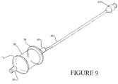
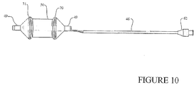
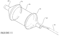
- FIGS. 9 , 10 , and 11 show a ScapusTM delivery system comprising a ScapusTM 46, luer fitting 62, perfusion tube 49 and a dog-bone shaped balloon delivery member 50.
- the luer fitting 62 is attached to the proximal side of the ScapusTM 46 and may be used to direct fluid for opening and closing the balloon delivery member 50.
- the balloon delivery member 50 is tightly disposed around the perfusion tube 49.
- the perfusion tube 49 is attached to the ScapusTM 46. Fluid may flow through the luer fitting 62, through the ScapusTM 46 and into the balloon delivery member 50 to inflate and deflate the balloon.
- a ScapusTM delivery system may also be used in a open surgery situation.
- a ScapusTM delivery system is used in non-beating heart surgeries.
- a ScapusTM delivery system may be used in an open chest surgery or robotic surgery.
- the preferred delivery system for delivering heart valves and tools in a trans-apical or trans-heart procedure is a ScapusTM delivery system. If a ScapusTM delivery system is not available, however, one may convert a catheter into a delivery system that is similar to a ScapusTM delivery system.
- a substantially thin, stiff guide stick is inserted into the catheter to give it similar characteristics as a ScapusTM.
- the guide-stick is loosely disposed within the catheter and occupies the space that a guidewire would otherwise occupy. But as opposed to a guidewire that cannot resist bending, a guide-stick is substantially rigid and can resist any unintended bending and torsion.
- a guide-stick disposed within a catheter in contrast to a catheter by itself, provides sufficient rigidity such that the resulting delivery system may more accurately and more precisely deliver a prosthesis during a beating heart procedure.
- the resulting delivery system is designed not to bend unless intended by the operator.
- the resulting delivery system can incorporate junctions or other means of bending at predetermined points to allow the operator to adjust the direction or angle of the delivery path in a controlled fashion.
- a substantially stiff guide-sleeve is loosely disposed on the outside of a catheter to give it similar characteristics as a ScapusTM delivery system.
- the catheter is loosely disposed within the delivery sleeve.
- the described delivery sleeve is substantially rigid and can resist any unintended bending and torsion.
- a guide-sleeve loosely disposed on a catheter in contrast to a catheter by itself, provides sufficient rigidity such that the resulting delivery system may more accurately and more precisely deliver a heart valve prosthesis 100 during a beating heart procedure.
- the resulting delivery system is designed not to bend unless intended by the operator.
- the resulting delivery system can incorporate junctions or other means of bending at predetermined points to allow the operator to adjust the direction or angle of the delivery path in a controlled fashion.
- the heart valve prosthesis 100 is shipped to the operating room in an expanded configuration.
- the heart valve prosthesis 100 is crimped down in diameter using crimpers known to anyone skilled in the art while the heart valve prosthesis 100 is loosely disposed around a delivery member.
- the crimping process occurs with the operating room or in vicinity of the operating room.
- the heart valve prosthesis 100 is further delivered to the target site for implantation.
- the heart valve prosthesis 100 is shipped to the operating room in a crimped configuration.
- the heart valve prosthesis 100 is crimped at the manufacturing facility in a careful, consistent, and controlled manner.
- the heart valve prosthesis 100 may be crimped directly onto a delivery member, such as a balloon delivery member 50.
- the heart valve prosthesis 100 may be crimped down to a size such that the internal diameter of the heart valve prosthesis 100 matches the external diameter of the delivery member.
- the heart valve prosthesis 100 remains in a crimped configuration until the heart valve prosthesis 100 reaches the operating room. Crimping the heart valve prosthesis 100 in a controlled environment will minimize structural deterioration to the heart valve prosthesis 100 and will simplify the procedure in the operating room.
- the crimped heart valve prosthesis 100 is disposed around the delivery member, and the heart valve prosthesis 100 is further delivered to the target site for implantation.
- a ScapusTM delivery system may be of a larger diameter than that of a catheter and is thus better suited for containing imaging transducers.
- an imaging transducer is placed onto the delivery system.
- the imaging transducer is placed within the delivery member.
- the imaging transducer is placed just proximal and/or distal to the delivery member.
- An external imaging transducer may be provided to view the operating field and imaging systems may be used at any time or throughout the duration of the surgery.
- the valvuloplasty assembly may include IVUS or other imaging sensors. Such imaging technology can be used to inspect native valve annulus and size the required heart valve prosthesis 100 after valvuloplasty has been completed.
- Imaging systems are well-known to anyone skilled in the art and include transesophageal echo, transthoracic echo, intravascular ultrasound imaging (IVUS), intracardiac echo (ICE), or an injectable dye that is radiopaque. Cinefluoroscopy may also be utilized.
- IVUS intravascular ultrasound imaging
- ICE intracardiac echo
- an injectable dye that is radiopaque or an injectable dye that is radiopaque.
- Cinefluoroscopy may also be utilized.
- the placement of imaging probes in relation to a balloon delivery member 50 has previously been described in co-owned PCT/US/04/33026 filed October 6, 2004 .
- the present invention also provides a method or system for removing the native valve with a valve removal device by access through the apical area of the heart.
- the valve removal may be accomplished as taught in co-pending U.S. Patent Application Serial Nos. 10/375,718 and 10/680,562 ( US 2003/216764 A1 and US 2005/75724 A1 ).
- the method may further comprise the step of removing at least a portion of the patient's heart valve by means of a cutting tool that is disposed on the ScapusTM.
- the cutting tool may be made of an electrically conductive metal that provides radiofrequency energy to the cutting tool for enhanced valve removal.
- the high frequency energy ablation is well known in the art.
- the delivery member includes cutting means comprising a plurality of jaw elements, each jaw element having a sharp end enabling the jaw element to cut through at least a portion of the native valve.
- the cutting means comprises a plurality of electrode elements, wherein radiofrequency energy is delivered to each electrode element, enabling the electrode element to cut through at least a portion of the native valve.
- the cutting means comprises a plurality of ultrasound transducer elements, wherein ultrasound energy is delivered to each transducer element enabling the transducer element to cut through at least a portion of the native valve.
- a ScapusTM with a valve removal system disposed on it is introduced through the apex and positioned substantially in the vicinity of the aortic valve.
- the native valve leaflets and debris e.g. calcium and valve leaflets
- the parts that are not contained by the valve removal systems are caught in the distal embolic protection filter.
- FIG. 5 and FIG. 6 show examples of distal embolic protection assemblies 68 and its relation to the delivery system 67. It is important that the distal embolic protection filter provides a means for trapping embolic material and debris. In one embodiment, it is also desired that the distal embolic protection filter provides a temporary valve. The filter and temporary valve assembly prevents flush back of blood, embolic material and debris, while still allowing fluid flow into the filter during surgery. The temporary valve may also temporarily do the work of an adjacent heart valve, such as the aortic valve. Thus in one embodiment of the present invention, the distal embolic protection assembly 68 provides a filter member for trapping embolic material that concurrently functions as a temporary valve.
- Distal embolic protection assemblies 68 used in both trans-apical and percutaneous procedures must be compressed and expanded to allow entry into small blood vessels or other body cavities. Combining both a one-way valve and a filter basket mechanism requires a significant amount of hardware making it difficult to compress the filter down sufficiently to be used during trans-apical and percutaneous procedures.
- FIG. 12 shows a sub-component of a distal embolic protection filter system that incorporates both a filter and the function of a temporary valve.
- the proximal mouth 73 of the filter consists of a proximal frame 74 that pushes against and makes a seal with the surrounding vasculature.
- the proximal frame 74 may, for example, push and seal against the inner wall of the aorta, causing all emboli and debris to flow through the filter assembly.
- the proximal frame 74 is made out of a shape memory alloy such as Nitinol, allowing it to expand into position.
- the distal end 76 of the filter sub-assembly is shown open. In other words, debris not caught in the filter mesh 78 may continue out through the distal end 76 of the filter sub-assembly, moving past the distal frame75.
- the distal frame 75 is made out of a shape memory alloy such as nitinol, allowing it to maintain an open configuration.
- FIG. 13 shows three inter-connected filter sub-assemblies shown in FIG. 12 . Although three sub-assemblies are shown, any number of two or more sub-assemblies will work.
- the length from the proximal frame to the distal frame of each sub-assembly is slightly different, thus separating the filters meshes of the different filter sub-assemblies 78, 79, and 82.
- the proximal frame 74 is shared by all the different filter sub-assemblies.
- a plurality of filter sub-assemblies are interconnected at the large inlet of the filters, while the downstream sides of the sub-assemblies have smaller openings allowing debris to flow through.
- the outermost filter-assembly is closed at the downstream end.
- cardiovascular tissue such as blood vessels and heart valves
- cardiovascular disease A variety of different methods have been developed to treat cardiovascular diseases associated with calcified atherosclerotic plaques and lesions. Such methods include mechanical removal or reduction of the lesion, such as bypass surgery, balloon angioplasty, mechanical debridement, atherectomy, and valve replacement.
- Calcified atherosclerotic plaques and lesions may also be treated by chemical means which may be delivered to the affected area by various catheter devices.
- U.S. Patent No. 6,562,020 by Constantz et al. discloses methods and systems for dissolving vascular calcified lesions using an acidic solution.
- a catheter delivers an acidic fluid to a localized vascular site.
- Such a system may, for example, decalcify a calcified heart valve by applying an acidic solution (such as hydrochloric acid, etc.)
- Constantz et al. The current percutaneous anti-calcification system disclosed by Constantz et al. is inserted through the femoral artery. Insertion through the femoral artery is impractical in the case of a trans-apical procedure as it requires another incision into the patient.
- the system by Constantz et al. may be adapted such that the delivery member controlling and holding the decalcification system is moved from the proximal side (i.e. side of the operator as in the case of femoral access) to the distal side.
- the methods and devices of the present invention may be adapted to provide a valve decalcification system, wherein a ScapusTM system is capable of providing the dissolution solution to the treatment site by access through the apical area of the heart.
- Suitable dissolution solutions are known in the art and are generally characterized as those which are capable of increasing the proton concentration at the treatment site to a desired level sufficient to at least partially dissolve the mineral component of a calcified atherosclerotic lesion.
- a trans-apical delivered ScapusTM system may also provide means for isolating the treatment site to prevent the dissolution solution from entering into the patient's circulatory system.
- the decalcification systems described and incorporated for reference above is adapted to be disposed on a ScapusTM as opposed to a catheter.
- Such means for isolating the treatment site may include a barrier, such as a dual balloon system on the catheter that inflate on both sides of the treatment site.
- FIG. 14 shows such a delivery system where a multilumen ScapusTM 46 connects to a perfusion tube 49 which in turn connects two balloons, a proximal balloon 92 and a distal balloon 93.
- the two balloons are shown inflated and in intimate contact with the walls of the aorta 94.
- the perfusion tube 49 is not present and the proximal balloon 92 and the distal balloon 93 are intimately in contact with the ScapusTM 43.
- Fluid may flow through the ScapusTM 46 to inflate the proximal balloon 92 and distal balloon 93 as well as provide the dissolution solution to the treatment site confined by the proximal balloon 92 and distal balloon 93.
- Andersen's intent and objective is to describe an expandable valve that is placed within a body channel or vasculature and uses the intimate contact created within the vasculature, body channel, or native valve as support to allow implantation.
- an expandable heart valve prosthesis 100 is implanted within a previously implanted man-made heart valve prosthesis and uses the intimate contact created with the previously implanted heart valve prosthesis for support. If the previously implanted heart valve prosthesis is removed, one will concurrently remove the expandable heart valve prosthesis 100 located within the previously implanted heart valve prosthesis.
- an expandable heart valve prosthesis 100 is mounted within a previously implanted heart valve prosthesis located within a heart.
- the expandable heart valve prosthesis 100 may be any valve that can be delivered minimally invasively, such as percutaneous or transapically delivered valves.
- the expandable heart valve prosthesis 100 is a balloon-expandable heart valve.
- the expandable heart valve prosthesis 100 is the 3F EntrataTM heart valve.
- the expandable heart valve prosthesis 100 is a self-expandable heart valve.
- the expandable heart valve prosthesis 100 is a valve expanded using some other mechanical or actuating means.
- the previously implanted heart valve prosthesis may be any valve either native or man-made.
- the previously implanted heart valve prosthesis is a mechanical valve.
- the previously implanted heart valve prosthesis is a tissue valve.
- the previously implanted heart valve prosthesis may also be made out of polyurethane or be a tissue-engineered valve.
- the previously implanted heart valve prosthesis can be an expandable heart valve.
- more than one expandable heart valve prosthesis 100 may be implanted within a previously implanted heart valve prosthesis. As such, multiple minimally invasive heart valve deliveries may be conducted without removing the existing valve or existing valves.
- the previously implanted heart valve prosthesis may be an aortic valve, mitral valve, pulmonary valve, or a tricuspid valve.
- the previously implanted heart valve prosthesis may also be a a homograft valve or a xenograft valve.
- Examples of previously implanted heart valve prosthesis include, but are not limited to, the Edwards Perimount Valve, the Edwards BioPhysio Valve, the Medtronic Hancock I Valve, the Medtronic Hancock M.O. Valve, the Medtronic Hancock II Valve, the Medtronic Mosaic Valve, the Medtronic Intact Valve, the Medtronic Freestyle Valve, the St. Jude Toronto Stentless Porcine Valve (SPV), and the St. Jude Prima Valve.
- the expandable heart valve prosthesis 100 may be made to fit well within the previously implanted heart valve prosthesis.
- the posts of the expandable heart valve prosthesis 100 are coordinated to fit the posts of the previously implanted heart valve prosthesis.
- the posts of the expandable heart valve prosthesis 100 matches the orientation for the posts of the previously implanted heart valve prosthesis.
- the inter-post separation angles of the expandable heart valve prosthesis 100 add up to 360°.
- the inter-post separation angle of the heart valve prosthesis 100 is 120°, 120°, and 120°; or 135°, 120°, and 105°; or 135°, 105°, and 120°; or 120°, 135°, and 105°; or 120°, 105°, and 135°; or 105°, 135°, and 120°; or 105°, 120°, and 135°.
- FIG. 15 shows an exploded view of FIG. 16 where a heart valve prosthesis 100 is shown implanted within a previously implanted heart valve prosthesis 101.
- the inflow ring or annulus 105 of the heart valve prosthesis 100 is aligned with the inflow ring or annulus 115 of the previously implanted heart valve prosthesis 101.
- the commissural posts 106 of the heart valve prosthesis 100 is aligned with the commissural posts 116 of the previously implanted heart valve prosthesis 101.
- the previously implanted heart valve prosthesis 101 is the same size or one size larger than the expandable heart valve prosthesis 100.
- the expandable heart valve prosthesis 100 is either 25mm or 27mm in size.
- the expandable heart valve prosthesis 100 is the same size as the previously implanted heart valve prosthesis 101.
- the expandable heart valve prosthesis 100 is larger than the previously implanted heart valve prosthesis 101.
- the expandable heart valve prosthesis 100 is smaller than the previously implanted heart valve prosthesis 101.
- Clinical records will specify the exact size used during an earlier implant.
- the size of the previously implanted heart valve prosthesis 101 will thus be known.
- In-vitro tests will show the best size expandable heart valve prosthesis 100 for a specific size and type target valve.
- the optimal size expandable heart valve can thus be determined from the clinical records from the previous heart valve implant.
- the size of the expandable heart valve prosthesis 100 to be used is determined from clinical records of prior implants.
- an expandable stent is implanted within a previously implanted heart valve prosthesis 101 prior to implanting the expandable heart valve prosthesis 100.
- valvuloplasty is used to expand the orifice of the previously implanted heart valve prosthesis 101 before implanting an expandable heart valve prosthesis 100 or before implanting an expandable stent.
- any delivery system may be used to deliver the expandable heart valve prosthesis 100.
- the delivery system is a catheter.
- the delivery system is a ScapusTM.
- the expandable heart valve prosthesis 100 may be delivered through any access point to the heart.
- the expandable heart valve prosthesis 100 is delivered minimally invasively.
- the expandable heart valve prosthesis 100 is delivered percutaneously.
- the expandable heart valve prosthesis 100 is delivered transapically.
- a ScapusTM valve delivery system may also be utilized in the case of self-expandable valves.
- the delivery system may be used for percutaneous valve delivery, trans-apical valve delivery, trans-heart delivery.
- the ScapusTM delivery system may be utilized in more invasive cardiac procedures such as open heart procedures.
- the ScapusTM delivery system is well suited for delivering the 3F Enable Aortic Heart ValveTM and the other valves described in co-owned U.S. applications entitled "Minimally Invasive Valve Replacement System" with the following application numbers: 10/680,733 ; 10/680,719 ; 10/680,728 ; 10/680,560 ; 10/680,716 ; 10/680,717 ; 10/680,732 ; 10/680,562 ; 10/680,068 ; 10/680,075 ; 10/680,069 ; 10/680,070 ; 10/680,071 ; and 10/680,567 ( US 2005/0075584 A1 ; US 2005/0075712 A1 ; US 2005/0075713 A1 ; US 2005/0075717 A1 ; US 2005/0075718 A1 ; US 2005/0075719 A1 ; US 2005/0075720 A1 ; US 2005/00757
- cardiac valves places in the heart of certain animal models calcify quickly may be used as basis for creating calcified animal models for use in the development and testing of cardiac valves.
- Open heart surgery valve replacement on adolescent sheep typically results in less than 40% success/survival in the aortic position, owing to the very small valve sizes and the use of full bypass.
- Open heart surgery valve replacement on adolescent sheep typically results in more than 80% success/survival in the mitral position owing to the larger valve sizes and the use of beating heart, partial bypass.
- Placing replacement valves in the mitral position during animal testing is not just used to reduce costs but is also considered a "worst-case" position due to higher backpressures. Replacement aortic and mitral valves are therefore frequently placed in the mitral position during animal studies.
- tissue valves are first implanted in adolescent sheep. The animals are survived for 10-200 days and the performance evaluated. Because of the increased propensity for calcification in animals, all the valves implanted are expected to be stenotic and/or incompetent due to calcification of tissue leaflets. Sheep may be evaluated at regular intervals using echo.
- Using either a percutaneous or trans-apical implant techniques place replacement heart valves within the calcified valves of adolescent sheep. Survive the test animals for 20 weeks (150 +/- 10 days) or as required by regulatory authorities. Monitor the replacement valves. Necropsy, pathology, and post mortem histology may be performed.
- the present invention may be divided in two phases:
- a calcified animal model is created by replacing the native valves of adolescent sheep with commercially available valves and surviving the animals.
- the heart valve replacement procedure is an on-pump procedure.
- the heart valve replacement procedure is a minimally invasive heart valve procedure, such as a percutaneous heart valve replacement procedure, or a trans-apical valve procedure. In the latter embodiment, the method described herein would allow testing of a minimally invasive heart valve repeat-procedure.
- the heart valve replacement procedure is conducted endoscopically. In yet another embodiment of the current invention, the heart valve replacement procedure is conducted using robots.
- drugs are utilized to adjust the rate of calcification.
- the valve implanted during Phase I is coated with a chemical substance used to adjust the rate of calcification.
- valve implanted is a tissue valve.
- the valve implanted is a mechanical valve.
- Implanted heart valves may include aortic valves, mitral valves, tricuspid valves, or pulmonary valves.
- a replacement valve may not necessarily be implanted in its intended position.
- an aortic valve may be implanted in the mitral position of the animal.
- a replacement aortic valve is implanted in the mitral position.
- multiple valves are implanted in different positions at the same time.
- valves are implanted in animals whose heart physiology and flow dynamics, as well as biochemistry, match humans as close as possible. Sheep and pigs are thus frequently used for heart valve testing.
- sheep is used as the animal model.
- pigs are used as the animal model. Any other primate may be used as an animal model.
- animals of subclass eutheria are used as the animal model.
- animals of the suborder anthropoidea e.g. monkeys and apes.
- the age of an animal affects the rate of calcification.
- the age of the animal is the equivalent of adolescence.
- the animals used are adults.
- Different monitoring equipment such as ultrasound, MRI, CT, and cinefluoroscopy, are used during the course of Phase I and Phase II.
- echo is used at 60, 90, and 120 days during Phase I to monitor the implanted valves.
- the animals in Phase I are survived for 90-120 days.
- the length of Phase I depends on factors such as what type of animal used and what type of tissue valves used.
- the valves may be monitored during Phase I. It may be possible to go to Phase II earlier based upon in-vivo evaluation.
- valves are implanted within the calcified valve orifices.
- Implant procedures include, but are not limited to minimally invasive valve procedures, percutaneous valve procedures, trans-apical valve procedure, on-pump valve procedure, endoscopic valve procedure, and robotic valve procedure.
- drugs are utilized to adjust the rate of calcification.
- the valve implanted during Phase II is coated with a chemical substance used to adjust the rate of calcification.
- Tissue valves include, but are not limited to tissue valve, mechanical valves, aortic valves, mitral valves, tricuspid valves, pulmonary valves.
- a replacement valve may not necessarily be implanted in its intended position.
- an aortic valve may be implanted in the mitral position of the animal.
- a replacement aortic valve is implanted in the mitral position.
- the animals in Phase I are survived for 20 weeks (150 +/- 10 days).
- the length of Phase II depends on guidelines provided by regulatory bodies.
- the minimally invasive valve delivery is conducted using a SCAPUSTM delivery system.
- the valve utilized is the 3F Therapeutics, Inc. EntrataTM valve.
- a balloon is used in the inferior vena cava to regulate pressure during the procedure.
- the replacement valve in Phase II is seated within the calcified valve orifice of the valve replacement conducted in Phase I. In another embodiment of the present invention, the replacement valve in Phase II is seated just upstream from the calcified valve orifice of the valve replacement conducted in Phase I. In another embodiment of the present invention, the replacement valve in Phase II is seated just downstream from the calcified valve orifice of the valve replacement conducted in Phase I.
Description
- This application claims priority to Provisional Application Serial No.
60/702,892 filed July 27, 2005 60/717,879 filed September 16, 2005 60/734,429 filed November 8, 2005 60/740,694 filed November 29, 2005 60/762,909 filed January 27, 2006 - The present invention relates generally to methods and systems for cardiovascular surgery.
- Various surgical techniques may be used to repair a diseased or damaged heart valve, such as annuloplasty (contracting the valve annulus), quadrangular resection (narrowing the valve leaflets), commissurotomy (cutting the valve commissures to separate the valve leaflets), or decalcification of valve and annulus tissue. Alternatively, the diseased heart valve may be replaced by a prosthetic valve. Where replacement of a heart valve is indicated, the dysfunctional valve is typically removed and replaced with either a mechanical or tissue valve.
- A number of different strategies have been used to repair or replace a defective heart valve. Open-heart valve repair or replacement surgery is a long and tedious procedure and involves a gross thoracotomy, usually in the form of a median sternotomy. In this procedure, a saw or other cutting instrument is used to cut the sternum longitudinally and the two opposing halves of the anterior or ventral portion of the rib cage are spread apart. A large opening into the thoracic cavity is thus created, through which the surgeon may directly visualize and operate upon the heart and other thoracic contents. The patient must typically be placed on cardiopulmonary bypass for the duration of the surgery.
- Open-chest valve replacement surgery has the benefit of permitting the direct implantation of the replacement valve at its intended site. This method, however, is highly invasive and often results in significant trauma, risk of complications, as well as an extended hospitalization and painful recovery period for the patient.
- Minimally invasive valve replacement procedures have emerged as an alternative to open-chest surgery. For example,
US 6,425,916 B1 relates to a system and method for implanting a cardiac valve which does not require a median sternotomy or major thoracotomy, but the devices and methods ofUS 6,425,916 B1 are preferably carried out by passing the valve through a blood vessel, preferably the femoral artery. Wikipedia Encyclopedia defines a minimally invasive medical procedure as one that is carried out by entering the body through the skin or through a body cavity or anatomical opening, but with the smallest damage possible to these structures. Two types of minimally invasive valve procedures that have emerged are percutaneous valve procedures and transapical valve procedures. Percutaneous valve procedures pertain to making small incisions in the skin to allow direct access to peripheral vessels or body channels to insert catheters. Trans-apical valve procedures pertain to making a small incision in or near the apex of a heart to allow valve access. The distinction between percutaneous valve procedures and minimally invasive procedures is also highlighted in a recent position statement of the Society of Thoracic Surgeons (STS), the American Association for Thoracic Surgery (AATS), and the Society for Cardiovascular Angiography and Interventions (SCAI; Vassiliades Jr. TA, Block PC, Cohn LH, Adams DH, Borer JS, Feldman T, Holmes DR, Laskey WK, Lytle BW, Mack MF, Williams DO. The clinical development of percutaneous heart valve technology: a position statement by the Society of Thoracic Surgeons (STS), the American Association for Thoracic Surgery (AATS), and the Society for Cardiovascular Angiography and Interventions (SCAI). J Thorac Cardiovasc Surg. 2005; 129:970-6). Because minimally invasive approaches require smaller incisions, they generally allow for faster patient recovery with less pain and bodily trauma. This, in turn, reduces the medical costs and the overall disruption to the life of the patient. - The use of minimally invasive approaches, however, introduces new complexities to surgery. An inherent difficulty in the minimally invasive percutaneous approach is the limited space that is available within the vasculature. Unlike open heart surgery, percutaneous heart surgery offers a surgical field that is only as large as the diameter of the blood vessel used for access. Consequently, the introduction of tools and prosthetic devices becomes a great deal more complicated as compared to open-chest surgeries. The device must be dimensioned and configured to permit it to be introduced into the vasculature, maneuvered therethrough, and positioned at a desired location. This may involve passage through significant convolutions, at some distance from the initial point of introduction, before placement can be made at the intended site.
- Andersen et al. describe a valve prosthesis implanted in a body channel by a way of catheterization in
U.S. Patent Nos. 5,411,442 ;5,840,081 ;6,168,614 ; and6,582,462 ; andU.S. Patent Application Serial No. 10/268,253 (US 2003/36795 A1 ). Catheters are hollow flexible tubes which can be passed inside blood vessels to the heart for diagnostic and treatment purposes. The delivery of catheter expanded valves through body channels such as that described by Andersen et al. is thus dependent on instruments of sufficiently small diameters, as well as adequate length and flexibility to navigate blood vessels. - Minimally invasive trans-apical valve replacement procedures have emerged as an alternative to both open-chest surgery and percutaneous valve surgeries. Bergheim et al. present improved methods and systems for cardia valve delivery in
U.S. Patent Application Serial Nos. 60/702,892 and10/831,770 US 2005/240200 A1 - In-vivo studies have shown that catheter-based valve delivery instrumentation may not be well adapted for trans-apical procedures. When inserting balloon catheters, as described in
U.S. Patent No. 6,582,462 andU.S. Patent Application Serial No. 10/831,770 , it is difficult to steer the balloon and the valve into position resulting from the lack of rigidity and the inherent flexibility of catheters. This is especially true in minimally invasive trans-apical valve procedures. By their very nature, catheters are designed to be long, flexible and bendable to navigate long distances through the vasculature. Catheters are also frequently susceptible to twisting. As a result, catheters are typically thin and made of flexible materials such as plastics or polymers. Catheters are also designed to be disposed on guidewires to better direct the catheter to the correct location. Even so, it is difficult to steadily and accurately deliver tools and devices over long distances. This is especially true in high flow situations such as a beating heart and in places offering the catheters a substantial amount of space to move within. Correct and accurate placement of a heart valve requires both accurate longitudinal positioning as well as rotational positioning. It is important to correctly place the valve as much as possible into a position that mimics that of the native valve to maximize durability and function. It is also important to prevent placement of the valve in a manner that blocks the left and right coronary outflow (as in the case of the aortic valve). There is hence a need to accurately maneuver and steer the valve during implantation. There is also a need for a device that is more suitable for delivering valves during trans-apical procedures. - During balloon-inflation of a flexible leaflet valve, such as a stented tissue valve, it is desired that the valve remain on the balloon until it is firmly positioned at the site of implantation. In the case of balloon-expandable valves, there is hence a need for devices designed to make sure the valve stays on the balloon during inflation.
- Bergheim further presents methods and assemblies for distal embolic protection in
U.S. Patent Application Serial No. 10/938,410 (US 2005/119688 A1 ). Here, Bergheim describes distal embolic protection assemblies for use during trans-apical valve surgery. In order to accommodate a distal embolic protection assembly alongside other valve insertion and replacement devices, it is important that the distal embolic protection assembly collapses down to a substantially small diameter to minimize the space it occupies - Macoviak et al. present a filter catheter used to capture potential emboli within the aorta during heart surgery and cardiopulmonary bypass in
U.S. Patent Application Serial No. 10/108,245 (US 2002/161394 A1 ). The filters described by Macoviak are adapted for use during cardiopulmonary bypass, and not during beating heart surgery. The filters described by Macoviak are also intended to be inserted through the femoral artery and further fail to incorporate a temporary valve, useful for capturing large amounts of debris while performing beating heart surgeries. There is hence a need for a filter system better suited for percutaneous and trans-apical valve surgeries. - Accordingly, while open-heart surgery produces beneficial results for many patients, numerous others who might benefit from such surgery are unable or unwilling to undergo the trauma and risks of current techniques. Therefore, what is needed are methods and devices for performing heart valve repair and replacement as well as other procedures within the heart and great vessels of the heart that provide greater ease of access to the heart valves than the current minimally invasive techniques, while at the same time reducing the trauma, risks, recovery time and pain that accompany more invasive techniques.
- The present invention is disclosed in independent claim 1 and the claims dependent on it and it provides systems for performing cardiovascular surgery, wherein access to the heart or great vessels is provided through the heart muscle. In preferred embodiments, access is provided through the apical area of the heart. The apical area of the heart is generally the blunt rounded inferior extremity of the heart formed by the left and right ventricles. In normal healthy humans, it generally lies behind the fifth left intercostal space from the mid-sternal line.
- The unique anatomical structure of the apical area permits the introduction of various surgical devices and tools into the heart without significant disruption of the natural mechanical and electrical heart function. Because the systems of the present invention permit direct access to the heart and great vessels through the apex, they are not limited by the size constraints which are presented by minimally invasive percutaneous valve surgeries. While access to the heart through peripheral (e.g. femoral, jugular, etc) vessels in percutaneous methods are limited to the diameter of the vessel (approximately 1 to 8 mm), access to the heart through the apical area is significantly larger (approximately 1 to 25 mm or more). Thus, apical access to the heart permits greater flexibility with respect to the types of devices and surgical methods that may be performed in the heart and great vessels.
- Accordingly, it is one object of this invention to provide devices for the repair, removal, and/or replacement of valves or their valve function by access through the heart muscle, particularly through the apical area of the heart. It should be noted that while reference is made herein of trans-apical procedures, it is intended for such procedures to encompass access to the heart through any wall thereof, and not to be limited to access through the apex only. While the apical area is particularly well suited for the purposes of the present invention, for certain applications, it may be desirable to access the heart at different locations, all of which are within the scope of the present invention.
- In one example of the present invention, a method for delivering a prosthesis to a target site in or near a heart is provided. The method comprises introducing a delivery system into the heart, preferably at or near the apex of the heart, wherein a prosthesis is disposed on the delivery member attached to the delivery system, advancing the prosthesis to the target site, and disengaging the prosthesis from the delivery member at the target site for implantation. In another embodiment of the current invention, a method for delivering a prosthesis to a pre-existing man-made valve within or near a heart is provided.
- The present invention also provides an implant system for delivering a prosthesis to a target site in or near a heart. In one embodiment of the present invention, the implant system comprises a delivery system, an access system, and a prosthesis. In one embodiment of the present invention, the access system is a trocar, cannula, or other suitable device to penetrate the heart, preferably at or near the apex of the heart; and the delivery system is substantially rigid and movably disposed within the trocar, wherein a prosthetic valve is disposed on the delivery member attached to the delivery system. In one embodiment of the present invention, the delivery system is termed a Scapus™ system. The term "Scapus™" denotes a slender or elongated rod shaped support structure that is substantially rigid. The term substantially rigid implies structural stability to withstand fluid pressures and other forces without unintended deformation. On the other hand, the Scapus™ may encompass junctions or other means of controlled bending to allow for directional control by the operator at predetermined points along the length of the Scapus™. In one embodiment of the current invention, the delivery system comprises a Scapus™ and a delivery member.
- The delivery system may be used to deliver a variety of prosthetic heart valves, including stented and stentless tissue valves. In one embodiment of the present invention, the delivery member comprises a mechanical or inflatable expanding member to facilitate implantation of the prosthetic valve at the target site. In another embodiment of the present invention, the delivery member is a balloon. In another embodiment of the present invention, the delivery member is a device used to expand folded valves. In yet another embodiment of the present invention, the delivery member may comprise an inflatable balloon member, whose distal and proximal ends have substantially larger cross-sectional areas than the portion of the balloon covered by the prosthesis, to prevent prosthesis migration. In a further embodiment of the present invention, the delivery system may comprise a duct or perfusion tube to allow blood flow through the delivery member during the procedure.
- It is a further object of the current invention to provide systems for converting a catheter into a Scapus™ delivery system. In one embodiment of the current invention, a substantially thin, stiff guide-stick is inserted into the catheter to give it similar characteristics as a Scapus™. In another embodiment of the current invention, a substantially thin, stiff guide-sleeve slides on the outside of a catheter to give it similar characteristics as a Scapus™.
- The delivery systems described herein may be used to deliver prosthetic valves to all four valves of the heart including the aortic valve, mitral valve, tricuspid valve, and pulmonary valve. Different anatomical features for the different heart valves (bicuspid vs. tricuspid valves) may call for different design heart valves. Therefore, in one embodiment of the present invention, the prostheses are designed to match the anatomy of the target valve position. In another embodiment of the current invention, the prosthesis is composed of a tissue valve mounted in a stent.
- One group of patients that will benefit from a trans-apical procedure is patients who have had previous valve replacements, and where replacement valves are failing. Rather than performing yet another open-chest procedure, many of these patients may be candidates for trans-apical valve replacements. This is especially the case for older patients who may not tolerate the stress of a new open-chest procedure. For these patients, who have a failing valve, one may seat the new trans-apical delivered prosthesis inside the failing valve. Therefore, in one embodiment of the present invention, the new prosthesis matches the configuration of the failing valve. Some patients who have had previous valve replacements, and whose valve replacement valves are failing may also be candidates for percutaneous valve procedures. For these patients, who have a failing valve, one may seat the new percutaneously delivered prosthesis inside the failing valve.
- The present invention also provides for devices for providing distal embolic protection and a temporary valve. In one embodiment of the present invention, the distal embolic protection system provides a filter member for trapping embolic material that concurrently functions as a temporary valve. The filter and temporary valve assembly prevents flush back of embolic material and debris, while still allowing fluid flow into the filter during surgery. The valve-filter combination may be compressed and expanded to allow entry into small blood vessels or other body cavities. In one embodiment of the present invention, the filter assembly is implanted in the heart or great vessel of the heart, downstream from the surgical site.
- In one embodiment of the present invention, a valvuloplasty balloon is inflated to increase the effective orifice area of a heart valve. In another embodiment of the present invention, the valvuloplasty balloon slides over the guide wire or actuation sleeve connected to the distal embolic protection device.
- Since a transapical procedure does not provide direct line of sight, sufficient imaging of the heart, valves, and other structures is important to provide diagnostics, guidance and feed-back during the procedure. A Scapus™ delivery system may be of a larger diameter than that of a catheter and is thus better suited for containing imaging transducers. Thus in one embodiment of the present invention, an imaging transducer is placed onto the delivery system. In another embodiment of the present invention, an external imaging transducer may be provided to view the operating field. Imaging systems may be used at any time or throughout the duration of the surgery. Imaging systems are well-known to those skilled in the art and include transesophageal echo, transthoracic echo, intravascular ultrasound imaging (IVUS), intracardiac echo (ICE), or an injectable dye that is radiopaque. Cinefluoroscopy may also be utilized.
- In another embodiment of the present invention, a positioning balloon is used to help position the Scapus™ correctly such that the new prosthesis (or alternatively other tools) land in the proper location.
- In yet another embodiment of the present invention, the system may further comprise means to remove at least a portion of the patient's heart valve by a cutting tool that is disposed on the delivery system.
- In a further embodiment of the present invention, the devices of the present invention may be adapted to provide a valve decalcification system, wherein the delivery system is capable of providing a dissolution solution to the treatment site by access through the apical area of the heart. The delivery system may be a catheter or a Scapus™ that is configured with means to both introduce and remove the dissolution solution to the treatment site. The delivery system may also provide means for isolating the treatment site to prevent the dissolution solution from entering into the patient's circulatory system. Such means for isolating the treatment site may include a barrier, such as a dual balloon system on the catheter that inflates on both sides of the treatment site.
- The present invention provides systems for creating a calcified animal model for use in the development and testing of cardiac valves.
- Although many of the above embodiments are referenced with respect to the aortic valve in the heart, the current invention may also be utilized for the mitral valve, tricuspid valve, and the pulmonary valve.
- The above aspects and other objects, features and advantages of the present invention will become apparent to those skilled in the art from the following description of the preferred embodiments taken together with the accompanying figures.
-
-
FIG. 1 is a partial front view of a patient's chest showing a prosthesis introduced into the apex of the heart through the fifth intercostal space using an implant system. -
FIG. 2 depicts a trocar penetrating the apex of the heart and into the left ventricle. -
FIG. 3 shows two independent balloon delivery members contained on the Scapus™ delivery system for providing both valvuloplasty and valve delivery. -
FIG. 4 shows a prosthetic valve disposed onto a "dog-bone" shaped balloon. -
FIG. 5 shows a Scapus™ delivery system and a distal embolic protection assembly. -
FIG. 6 shows a Scapus™ delivery system and a distal embolic protection assembly. -
FIG. 7 shows the distal embolic protection system positioned in the aorta and inserted through the femoral artery. -
FIG. 8 shows a prosthetic valve implanted in the heart. -
FIG. 9 shows a Scapus™ delivery system. -
FIG. 10 shows a Scapus™ delivery system. -
FIG. 11 shows a close-up of a balloon delivery member of a Scapus™ delivery system. -
FIG. 12 shows a distal embolic protection subsystem. -
FIG. 13 shows a temporary valve distal embolic protection system. -
FIG. 14 shows a dual balloon system for providing a valve decalcification system. -
FIG. 15 shows an exploded view of a heart valve implanted inside a previously implanted heart valve. -
FIG. 16 shows an a heart valve implanted inside a previously implanted heart valve. -
FIGS. 1 through 16 show embodiments of the methods and systems of the present invention for the repair, removal, and/or delivery of prosthetic valves, and also for providing distal embolic protection and a temporary valve during cardiovascular procedures. -
FIG. 1 is a partial front view of thechest 11 of apatient 10 and shows the position of asurgical tool 29 in relation to other anatomical landmarks, such as thesternum 13, xiphoid 14,ribs 15, andheart 12. Asurgical tool 29 is depicted as entering the body cavity through the fifthintercostal space 16 and through the apex of theheart 12. Thesurgical tool 29 is seen inserted through anaccess system 31. Thesurgical tool 29 may contain devices or systems used for surgical procedures in or on the heart or the greater vessels of the heart. In one embodiment of the current invention, thesurgical tool 29 is a delivery system. In another embodiment of the current invention, thesurgical tool 29 may be a distal embolic protection device. Thesurgical tool 29 may enter the body cavity through variousother locations chest 11. In another embodiment of the current invention, thesurgical tool 29 may be a plurality of devices. In one embodiment of the current invention, thesurgical tool 29 is both a delivery system and a distal embolic protection system. - In one embodiment of the present invention, the implant system comprises an access system, delivery system, and a prosthesis. In one embodiment of the current invention, the prosthesis is a heart valve prosthesis. In another embodiment of the current invention, the
access system 31 is a trocar, cannula, or other suitable device for penetrating the apex 18 of theheart 12. In another embodiment of the current invention, the delivery system is composed of a delivery member, wherein the prosthetic valve is disposed on the delivery member. In another embodiment of the current invention, the delivery system is substantially rigid. In yet another embodiment of the current invention, the substantially rigid support structure of the delivery system is called a Scapus™. Inherent in its definition, the term Scapus™ implies a rigid support structure with other devices, tools, and assemblies attached to it. In one embodiment of the current invention, the delivery member of the delivery system is attached to the Scapus™: - The delivery system described in the current invention presents major advances over the use of catheters as delivery systems for procedures in close vicinity of the heart. By their very nature, catheters are designed to be flexible to navigate long distances. Catheters must also be able to twist and bend to move through bends in the vasculature, such as those encountered in percutaneous procedures. Catheters are also designed to be disposed on guidewires to better direct the catheter to the correct location. Even with the use of guidewires, it is difficult to steadily and accurately deliver tools and devices over long distances. This is especially true in high flow situations such as a beating heart procedure. Correct and accurate placement of a heart valve requires both accurate longitudinal positioning as well as rotational positioning. It is important to correctly place the valve as much as possible into a position that mimics that of the native valve to maximize durability and function. It is also important to prevent placement of the valve in a manner that blocks the left and right coronary outflow (as in the case of the aortic valve).
- Accurate delivery of cardiac valves in trans-apical procedures requires accurate and precise longitudinal and rotational positioning. Longitudinal positioning implies positioning along the length of the aorta. Rotational positioning implies rotational positioning around the lengthwise direction of the aorta. The route from the apex of the heart to all four cardiac valves is also a substantially straight line, meaning that the maneuvering features such as bending, twisting, and torsion of a catheter are not typically desired. In fact, the inherent maneuvering features of a catheter are disadvantageous in this procedure as it allows bending and torsion and is not able to hold the delivery member in place during valve implantation. The blood flow and pressure inherent in a beating heart procedure in combination with a catheter delivery system therefore does not allow accurate and precise delivery of prosthetic valves.
- An object of the present invention is therefore to provide a delivery system that is substantially rigid to resist any unintended bending and torsion. A Scapus™, in contrast to a catheter, provides sufficient rigidity to accurately and precisely deliver a prosthesis during a beating heart procedure. A Scapus™ delivery system is designed not twist or bend unless intended by the operator. The Scapus™ of the present invention can incorporate junctions or other means of bending at predetermined points to allow the operator to adjust the direction or angle of the delivery path in a controlled fashion.
- In one embodiment of the present invention, the Scapus™ provides rigid support between the operator and the distal portion of the delivery system located in the heart. In contrast to catheter delivery systems, a Scapus™ delivery system may incorporate a larger cross-sectional area since access through the heart walls provides a larger access port diameter (in some instances up to 25 mm or more) compared with the vasculature (0 to 8 mm or less).
- In one embodiment of the current invention, the Scapus™ is made of a material that substantially resists bending and torsion. One example of such a material is stainless steel or substantially strong polymer plastics.
- In one embodiment of the current invention, the Scapus™ is a solid rod. In yet another embodiment of the current invention, the Scapus™ is a hollow rod. A Scapus™ may contain one or more lumens for moving fluid. A Scapus™ may also contain actuating members such as rods, wires, guidewires, or catheters. A Scapus™ may also conduct or transmit electricity or electrical signals and may also transmit light or light signals. A Scapus™ may also transmit radiation or other forms of energy such as ultrasound, ultraviolet light, infrared light, or gamma rays.
- A catheter used for percutaneous valve procedures are typically longer than 50cm to navigate through the vasculature. By contrast, the Scapus™ length can be less than 50cm. In preferred embodiments of the present invention, the length of the Scapus™ can be about 15-30 cm in total, of which about 10 cm may be inserted into heart, and the remaining length left outside.
- The methods and systems of the present invention may be used to implant a variety of heart valve prosthesis known in the art, including stented and stentless tissue valves. The methods and systems of the present invention may also be used to implant a variety of stents. In one embodiment of the present invention, the prosthetic delivery member is located towards the distal end of the delivery system. Stented valves may be expandable by mechanical or balloon expansion devices, or they may be self-expanding. Self-expanding stents may be constructed from elastic materials such as memory shaped metal alloys. An example of a memory shaped metal alloy is that of Nitinol. The valves are expanded using the valve expansion member located on the delivery system. In one embodiment of the present invention, the delivery member is a mechanically actuated device used to expand stented valves. In another embodiment of the current invention, the delivery member is a balloon expansion device. In another embodiment of the present invention, the delivery member is a balloon used for radial expansion. In yet another embodiment of the current invention, the delivery member contains a self-expandable heart valve. There are numerous methods and systems for releasing a self-expandable heart valve. One example is
U.S. Patent No. 6,682,558 . - Stented valves may also be expandable by unfolding the valve. The valve may be unfolded by using a balloon or mechanical expansion device. Alternatively, the folded valves may be self-expanding. Self-expanding stents may be constructed from elastic materials such as memory shaped alloys. The valves are expanded using the valve expansion member located on the delivery system. In one embodiment of the present invention, the delivery member is a mechanically actuated device used to expand stented valves that have been folded. In another embodiment of the current invention, the delivery member is a balloon expansion device. In such an embodiment, the balloon and stented valve have been folded together. When inflated, the balloon and stented valve return to their original shape. When unfolding a stented valve using a mechanical expansion device or a balloon, the stent making up the stented valve is typically made from a non-memory shaped alloy. Examples of suitable materials include stainless steel, polymers, plastics, and non-memory shaped metals. In another embodiment of the present invention, the delivery member is used to unfold stented valves made from memory shaped alloys. In one embodiment of the present invention, the delivery member consists of a hollow tube in which the stented valve is placed into and a plate or actuating mechanism just proximal to the valve used to push out the valve out of the hollow tube.
- Alternatively, the methods and devices of the present invention may also be used to implant a stentless prosthetic heart valve. In one embodiment of the present invention, the delivery member is adapted to position the tissue valve at the target site and the deliver member further comprises a means to suture or staple the tissue valve to the valve annulus.
- Examples of suitable prosthetic valves are disclosed in the following commonly owned patents:
U.S. Patent Nos. 6,682,559 ;5,480,424 ;5,713,950 ;5,824,063 ;6,092,529 ;6,270,526 ;6,673,109 ;6,719,787 ;6,719,788 ; and6,719,789 . Examples of other valve assemblies suitable for use in connection with the present invention are described inU.S. Patent Nos. 5,411,552 ;6,458,153 ;6,461,382 ; and6,582,462 . Yet another valve suitable for use in connection with the present invention is disclosed inU.S. Patent Application Serial No. 10/680,071 (US 2005/75731 A1 ). - Access systems suitable for use in connection with the present invention typically comprise a hollow lumen and a first and second ends. In one embodiment of the present invention, the
access system 31 is a trocar. The first end comprises a means for penetrating the heart tissue and the second end comprises a port through which the valve delivery system may be introduced into the hollow lumen of the trocar and into the heart.FIG. 2 depicts anaccess system 31 penetrating through the apex 18 of theheart 12. The moving direction of theaccess system 31 is indicated by thearrow 19. Theaccess system 31 can enter either theright ventricle 20 or theleft ventricle 21. To access the aortic or mitral valve, thetrocar 31 would preferably pass through theleft ventricle 21. This yields direct access to the aortic or mitral valve. To access the pulmonary or tricuspid valve, thetrocar 31 would preferably pass through theright ventricle 20. - In another embodiment of the present invention, the
access system 31 further comprises a valve disposed within its lumen. The valve is designed to reduce significant backflow of blood out of theheart 12 after theaccess system 31 is inserted into the beatingheart 12, while at the same time permitting the introduction of the delivery member and other surgical devices in through theaccess system 31. Othersuitable access systems 31 and devices are well known in the art and are disclosed inU.S. Patent Nos. 5,972,030 ;6,269,819 ;6,461,366 ;6,478,806 ; and6,613,063 . - In one embodiment of the present invention, the operator places a pursestring suture on the apex 18 of the
heart 12 to create a seal around theaccess system 31. Another embodiment of the present invention allows the use of the Scapus™ delivery system without anaccess system 31. It is contemplated that the physician becomes familiar with the advantages of the present invention and thus may find it unnecessary to use a trocar. In the latter case, the distal embolic protection system and the delivery system is placed directly through an incision in the apex 18 or other area of the heart wall. In another embodiment of the current invention, a delivery sleeve or delivery sheath is placed on the delivery system. - In one embodiment of the present invention, an off-the-shelf valvuloplasty balloon catheter is introduced through the
access system 31 into the apex 18 of theheart 12, positioning the balloon of the catheter within the valve and valve annulus. Valvuloplasty balloons are well known to anyone skilled in the art. Once the balloon is placed within the valve, it may be inflated to widen a stiff or narrowed heart valve (stenotic heart valve) improving blood flow through the heart and to the rest of the body. Previous methods for performing valvuloplasty required the insertion of a catheter typically through the femoral artery or femoral vein which is then guided through the heart and positioned through the diseased heart valve. The methods and devices of this present invention, however, provide a more direct route to the valve to be treated. - In another embodiment of the present invention, the delivery member of the delivery system described in the current invention is used to valvuloplasty the diseased valve. In such an embodiment, the delivery member of the delivery system is first guided to the diseased heart valve and positioned within the valve and valve annulus. After expanding the valve orifice, the delivery system is withdrawn from the
access system 31 and a new prosthetic valve is placed onto the valve delivery system. The valve delivery system is further introduced through theaccess system 31 and the delivery member moved into position within the valve orifice to expand and implant the valve. - In yet another embodiment of the present invention, two independent delivery members are contained on the delivery system. Such a system is shown in
FIG. 3 . Here, thedelivery system 67 includes aScapus™ 46, aperfusion tube 49, and two independently operatedballoon delivery members delivery system 67 to be used both for valvuloplasty and valve delivery. In such an embodiment, the mostdistal delivery member 91 is first guided to the diseased heart valve and positioned within the valve and valve annulus. After expanding the valve orifice, thedelivery system 67 is moved such that the second mostproximal delivery member 90, onto which the prosthetic valve is placed, is moved within the valve and valve annulus to expand and implant the valve. In a further embodiment of the present invention, noperfusion tube 49 is present and theballoons Scapus™ 46. The use of twoballoons Figure 3 is not only practical in trans-apical valve procedures, but also in percutaneous valve procedures. Thus, in one embodiment of the present invention, theScapus™ 46 shown inFigure 3 is a catheter. In a further embodiment of the foregoing embodiment, the catheter is a multilumen catheter. - Regardless of the type of valve delivery member utilized, it is important that the prosthetic valve remain securely attached to the delivery member during implantation. This is especially true if the operator accidentally or intentionally lowers the pressure in the ballon (via a syringe, etc). Thus, the present invention further provides balloons that are shaped such that the distal and proximal ends of the balloon, not covered by the prosthetic valve, are larger in area, and thus prevents migration of the valve. Such a balloon may take the shape of a "dog-bone".
-
FIG. 4 shows aballoon 50 delivery member whoseproximal end 70 anddistal end 71 have a larger cross sectional area than the middle portion of the balloon in intimate contact with theprosthetic valve 100.FIG. 4 also shows aperfusion tube 49 extending through the balloon from theproximal end 70 to thedistal end 71 of theballoon delivery member 50 allowing fluid to flow through the length of theballoon delivery member 50. In one embodiment of the present invention, theballoon delivery member 50 does not contain aperfusion tube 49. The orientation of theprosthetic valve 100 on theballoon delivery member 50 shown inFIG. 4 in relation to theproximal end 70 anddistal end 71 of theballoon delivery member 50 depends on the implantation method in relation to the blood flow direction through the native valve. The orientation shown inFIG. 4 is preferred for apical implantation. In another embodiment of the present invention, theprosthetic valve 100 is oriented the opposite direction on theballoon delivery member 50. - In one embodiment of the present invention, the
distal end 71 andproximal end 70 of theballoon delivery member 50 has a material coating that has a larger coefficient of friction with the prosthetic valve as opposed to the middle portion of theballoon delivery member 50. In the case of aballoon delivery member 50, an example of a material that has a larger coefficient of friction with a prosthetic valve as compared to the balloon is cloth. Increasing the roughness in the plastic making up the balloon will also increase the coefficient of friction with the prosthetic valve. - The "dog-bone" shape
balloon delivery member 50 described herein is not limited to Scapus™ delivery systems. Such balloons can be utilized in any type of stent delivery. Thus, in one embodiment of the present invention, the "dog-bone"balloon delivery member 50 described herein may be utilized in any type of stent or prosthetic valve delivery system. In one embodiment of the present invention, the "dog-bone"balloon delivery member 50 is utilized on a catheter valve delivery system, such as those used for percutaneous valve delivery. -
FIG. 5 depicts adelivery system 67 consisting of aScapus™ 46, balloon inflation tube 45, proximal balloondelivery member connector 48, distalballoon member connector 51,perfusion tube 49, and aballoon delivery member 50. In a preferred embodiment of the present invention, the proximal balloondelivery member connector 48 and the distal balloondelivery member connector 51 have a hole or a plurality of holes allowing blood to flow through theperfusion tube 49 and hence through theballoon delivery member 50. In another preferred embodiment, theScapus™ 46 comprises a substantially rigid solid rod. In one embodiment of the present invention, theScapus™ 46 and the balloon inflation tube 45 are glued or fused together at a plurality of points along the extent of theScapus™ 46. In another embodiment of the present invention, theScapus™ 46 contains one or more inside lumens. In yet another embodiment of the current invention, the balloon inflation tube 45 is disposed within theScapus™ 46. In another embodiment of the current invention, the balloon inflation tube 45 is one of the internal lumens of theScapus™ 46. In yet another embodiment of the current invention, theScapus™ 46 may be bent in a controlled fashion, using a bending force. As used herein, bending force here means bending moment that can be created by the use of the operators' hands. TheScapus™ 46 cannot be bent by the much smaller forces imposed by the blood flow and the beating heart. TheScapus™ 46 may further incorporate junctions or other bending means that allow for operator-controlled bending of theScapus™ 46 at predetermined points. -
FIG. 5 also shows a distalembolic protection assembly 68. The distal embolic protection assembly consists of aframe 55 and aporous bags 56. In one embodiment of the present invention, the distal inlet portion of thefilter mouth 53 includes a temporary valve. - In one embodiment of the present invention, the
delivery system 67 is inserted through thetrocar 31 into theleft ventricle 21 and advanced towards the native aortic valve of theheart 12. Thedelivery system 67 may be composed of a substantiallyrigid Scapus™ 46 and a delivery member. Theheart valve prosthesis 100 is disposed around theballoon delivery member 50 and delivered to the target site for implantation. The length ofballoon delivery members 50 suitable for the purposes of the present invention will depend on the height of theprosthetic valve 100 to be implanted. -
FIG. 6 shows adelivery system 67 comprising aperfusion tube 49,balloon delivery member 50, and aScapus™ 46. Here, theScapus™ 46 is rigidly attached to theperfusion tube 49. In one embodiment of the current invention, theScapus™ 46 has a lumen that extends to theballoon delivery member 50 and serves to inflate and deflate the balloon. Theactuation sleeve 43 and guidewire 41 is loosely disposed within theperfusion tube 49. - In one embodiment of the present invention, the distal
embolic protection assembly 68,actuation sleeve 43 and guidewire 41 withinactivation sleeve 43 is movably disposed within theScapus™ 46 of thedelivery system 67 andballoon delivery member 50 shown inFIG. 6 . In yet a further embodiment of the present invention, the distalembolic protection assembly 68 may be collapsed and moved through theScapus™ 46 andballoon delivery member 50. In one embodiment of the present invention, the delivery system shown inFIG. 6 is inserted through thetrocar 31 in two steps: first the distalembolic protection assembly 68; second thedelivery system 67 andballoon delivery member 50. After having introduced thetrocar 31 through the apex 18 of theheart 12, the distalembolic protection assembly 68 is moved in a collapsed configuration through thetrocar 31 and theleft ventricle 21 and placed downstream from the aortic valve. Once the distalembolic protection assembly 68 is in position, the distalembolic protection assembly 68 is expanded to seal the inside circumference of the aorta. Expansion takes place by moving theactuation sleeve 43 relative to theguidewire 41. All circulation through the aorta will hence have to be filtered in theporous bag 56 of the distalembolic protection assembly 68. Theguidewire 41 andactuation sleeve 43 extends from the proximal side of the distalembolic protection assembly 68 to the outside of thebody 10 and is accessible to the operator. In one embodiment of the present invention, theactuation sleeve 43 may also be used as a guidewire to move theScapus™ 46 into position. Thus in one embodiment of the current invention, the Scapus™ delivery system may be loosely disposed on aguidewire 41. In yet another embodiment of the present invention, theperfusion tube 49 functions as theactuation sleeve 43 to open and collapse the distal embolic protection catheter. - Distal
embolic protection assemblies 68 may be introduced through the apex 18 of theheart 12. Such embodiments are summarized in co ownedU.S. Application No. 10/938,410 (US 2005/119688 A1 ). Distalembolic protection assemblies 68 may also be inserted through arteries such as the femoral artery such as those disclosed byMacoviak, et al in U.S. Application No. 10/108,245 (US 2002/161394 A1 ). In another embodiment of the present invention, the distal embolicprotection filter assembly 68 is introduced through the femoral artery and moved to the aortic arch, positioned just downstream of the aortic valve as shown inFIG. 7 . Adelivery sheath 66 is used to collapse the filter assembly composed of thefilter frame 55 and theporous bag 56. In a further embodiment of the current invention, aguidewire 65 is attached to theframe 55 on the proximal side of thefilter assembly 68 and continues through the aortic valve and out through thetrocar 31 and out through thebody 10. Theguidewire 65 may be used for guiding thedelivery system 67 into position through thetrocar 31 and the apex 18 of the heart. The way theguidewire 65 is attached to the mouth of thefilter 55 is for illustrational purposes only. Anyone skilled in the art will appreciate there are many different ways of attaching a guidewire to themouth 55 of the filter and different opening and closing mechanism for the filter. Other aortic filter systems described in prior art for femoral artery insertion may also be adapted for this procedure. - In one embodiment of the current invention, the
delivery sheath 66 shown inFIG. 7 is aScapus™ 46 delivery system. TheScapus™ 46 delivery system may slide across the guidewire. Theporous bag 56 may also be inserted and removed through the delivery system. - Once the distal
embolic protection assembly 68 has been placed into position, theScapus™ 46 of thedelivery system 67 slides over theactuation sleeve 43 through the apex 18 of theheart 12. In one embodiment of the present invention, thedelivery system 67 slides over theguidewire balloon delivery member 50 is positioned in the aorta and within the aortic valve and aortic valve annulus. In one embodiment of the present invention, the distalembolic protection system 68 andvalve delivery system 67 is inserted through the apex 18 together. - A collapsed replacement
heart valve prosthesis 100 is disposed on theballoon delivery member 50. Thedelivery system 67 with the attached replacement prosthetic valve slides over the actuation sleeve and is introduced into the port of theaccess system 31 and through the apex 18 of theheart 12. Theballoon delivery member 50 with the attachedheart valve prosthesis 100 is positioned in the aorta and within the aortic valve and aortic valve annulus. Theballoon delivery member 50 is expanded by moving fluid through the balloon inflation tube 45. The balloon inflation tube 45 connects fluid to theballoon delivery member 50. In one embodiment of the present invention, the device used to move fluid through the balloon inflation tube 45 is a syringe. Theballoon delivery member 50 expands in a radial direction when filled with fluid through the balloon inflation tube 45 causing the replacementprosthetic valve 100 to exert force against the existing valvular leaflets and the walls of the vessel. - In one embodiment of the present invention, the valve replacement procedure described herein is done more than once. A repeat procedure may, for example, be performed in patients who cannot tolerate an open chest surgery.
- Once the
heart valve prosthesis 100 is implanted, theballoon delivery member 50 is deflated and thevalve delivery system 67 is withdrawn from the body. The distalembolic protection assembly 68 is further withdrawn from thebody 10. In one embodiment of the present invention, the distalembolic protection assembly 68 and thevalve delivery system 67 are withdrawn from the body together. In one embodiment of the present invention, a distalembolic protection assembly 68 is not utilized. In yet another embodiment of the present invention, the distalembolic protection assembly 68 is left in the body for some time (up to 7 days) after the operation to make sure that theporous bag 56 of the distalembolic filter assembly 67 has collected all the debris. -
FIG. 8 shows an implantedheart valve prosthesis 100 positioned in the aortic valve position. -
FIGS. 9 ,10 , and11 show a Scapus™ delivery system comprising aScapus™ 46, luer fitting 62,perfusion tube 49 and a dog-bone shapedballoon delivery member 50. The luer fitting 62 is attached to the proximal side of theScapus™ 46 and may be used to direct fluid for opening and closing theballoon delivery member 50. Theballoon delivery member 50 is tightly disposed around theperfusion tube 49. Theperfusion tube 49 is attached to theScapus™ 46. Fluid may flow through the luer fitting 62, through theScapus™ 46 and into theballoon delivery member 50 to inflate and deflate the balloon. - It is important to note that although the different inventions described herein is typically described in reference to trans-apical valve implantation, they may also be used in non-beating heart surgeries. A Scapus™ delivery system, for example, may also be used in a open surgery situation. Thus, in one embodiment of the current invention, a Scapus™ delivery system is used in non-beating heart surgeries. In another embodiment of the current invention, a Scapus™ delivery system may be used in an open chest surgery or robotic surgery.
- The preferred delivery system for delivering heart valves and tools in a trans-apical or trans-heart procedure is a Scapus™ delivery system. If a Scapus™ delivery system is not available, however, one may convert a catheter into a delivery system that is similar to a Scapus™ delivery system.
- In one embodiment of the current invention, a substantially thin, stiff guide stick is inserted into the catheter to give it similar characteristics as a Scapus™. The guide-stick is loosely disposed within the catheter and occupies the space that a guidewire would otherwise occupy. But as opposed to a guidewire that cannot resist bending, a guide-stick is substantially rigid and can resist any unintended bending and torsion. A guide-stick disposed within a catheter, in contrast to a catheter by itself, provides sufficient rigidity such that the resulting delivery system may more accurately and more precisely deliver a prosthesis during a beating heart procedure. The resulting delivery system is designed not to bend unless intended by the operator. The resulting delivery system can incorporate junctions or other means of bending at predetermined points to allow the operator to adjust the direction or angle of the delivery path in a controlled fashion.
- In another embodiment of the current invention, a substantially stiff guide-sleeve is loosely disposed on the outside of a catheter to give it similar characteristics as a Scapus™ delivery system. The catheter is loosely disposed within the delivery sleeve. The described delivery sleeve is substantially rigid and can resist any unintended bending and torsion. A guide-sleeve loosely disposed on a catheter, in contrast to a catheter by itself, provides sufficient rigidity such that the resulting delivery system may more accurately and more precisely deliver a
heart valve prosthesis 100 during a beating heart procedure. The resulting delivery system is designed not to bend unless intended by the operator. The resulting delivery system can incorporate junctions or other means of bending at predetermined points to allow the operator to adjust the direction or angle of the delivery path in a controlled fashion. - In one embodiment of the present invention, the
heart valve prosthesis 100 is shipped to the operating room in an expanded configuration. Theheart valve prosthesis 100 is crimped down in diameter using crimpers known to anyone skilled in the art while theheart valve prosthesis 100 is loosely disposed around a delivery member. The crimping process occurs with the operating room or in vicinity of the operating room. Theheart valve prosthesis 100 is further delivered to the target site for implantation. - In one embodiment of the current invention, the
heart valve prosthesis 100 is shipped to the operating room in a crimped configuration. Theheart valve prosthesis 100 is crimped at the manufacturing facility in a careful, consistent, and controlled manner. Theheart valve prosthesis 100 may be crimped directly onto a delivery member, such as aballoon delivery member 50. Alternatively, theheart valve prosthesis 100 may be crimped down to a size such that the internal diameter of theheart valve prosthesis 100 matches the external diameter of the delivery member. Theheart valve prosthesis 100 remains in a crimped configuration until theheart valve prosthesis 100 reaches the operating room. Crimping theheart valve prosthesis 100 in a controlled environment will minimize structural deterioration to theheart valve prosthesis 100 and will simplify the procedure in the operating room. When reaching the operating room, the crimpedheart valve prosthesis 100 is disposed around the delivery member, and theheart valve prosthesis 100 is further delivered to the target site for implantation. - Since a transapical procedure does not provide direct line of sight, sufficient imaging of the heart, valves, and other structures is important to provide diagnostics, guidance and feed-back during the procedure. A Scapus™ delivery system may be of a larger diameter than that of a catheter and is thus better suited for containing imaging transducers. Thus in one embodiment of the present invention, an imaging transducer is placed onto the delivery system. In one embodiment of the current invention, the imaging transducer is placed within the delivery member. In another embodiment of the present invention, the imaging transducer is placed just proximal and/or distal to the delivery member.
- An external imaging transducer may be provided to view the operating field and imaging systems may be used at any time or throughout the duration of the surgery. The valvuloplasty assembly may include IVUS or other imaging sensors. Such imaging technology can be used to inspect native valve annulus and size the required
heart valve prosthesis 100 after valvuloplasty has been completed. - Imaging systems are well-known to anyone skilled in the art and include transesophageal echo, transthoracic echo, intravascular ultrasound imaging (IVUS), intracardiac echo (ICE), or an injectable dye that is radiopaque. Cinefluoroscopy may also be utilized. The placement of imaging probes in relation to a
balloon delivery member 50 has previously been described in co-ownedPCT/US/04/33026 filed October 6, 2004 . - The present invention also provides a method or system for removing the native valve with a valve removal device by access through the apical area of the heart. By way of example, the valve removal may be accomplished as taught in co-pending
U.S. Patent Application Serial Nos. 10/375,718 and10/680,562 US 2003/216764 A1 andUS 2005/75724 A1 ). - In one embodiment of the present invention, the method may further comprise the step of removing at least a portion of the patient's heart valve by means of a cutting tool that is disposed on the Scapus™. In another aspect of the present invention, the cutting tool may be made of an electrically conductive metal that provides radiofrequency energy to the cutting tool for enhanced valve removal. The high frequency energy ablation is well known in the art.
- In another embodiment of the present invention, the delivery member includes cutting means comprising a plurality of jaw elements, each jaw element having a sharp end enabling the jaw element to cut through at least a portion of the native valve. In another aspect, the cutting means comprises a plurality of electrode elements, wherein radiofrequency energy is delivered to each electrode element, enabling the electrode element to cut through at least a portion of the native valve. In a further aspect of the present invention, the cutting means comprises a plurality of ultrasound transducer elements, wherein ultrasound energy is delivered to each transducer element enabling the transducer element to cut through at least a portion of the native valve.
- A Scapus™ with a valve removal system disposed on it is introduced through the apex and positioned substantially in the vicinity of the aortic valve. The native valve leaflets and debris (e.g. calcium and valve leaflets) are removed. The parts that are not contained by the valve removal systems are caught in the distal embolic protection filter.
- The present invention also provides for devices and methods for providing distal embolic protection during the procedure.
FIG. 5 andFIG. 6 show examples of distalembolic protection assemblies 68 and its relation to thedelivery system 67. It is important that the distal embolic protection filter provides a means for trapping embolic material and debris. In one embodiment, it is also desired that the distal embolic protection filter provides a temporary valve. The filter and temporary valve assembly prevents flush back of blood, embolic material and debris, while still allowing fluid flow into the filter during surgery. The temporary valve may also temporarily do the work of an adjacent heart valve, such as the aortic valve. Thus in one embodiment of the present invention, the distalembolic protection assembly 68 provides a filter member for trapping embolic material that concurrently functions as a temporary valve. - Distal
embolic protection assemblies 68 used in both trans-apical and percutaneous procedures must be compressed and expanded to allow entry into small blood vessels or other body cavities. Combining both a one-way valve and a filter basket mechanism requires a significant amount of hardware making it difficult to compress the filter down sufficiently to be used during trans-apical and percutaneous procedures. -
FIG. 12 shows a sub-component of a distal embolic protection filter system that incorporates both a filter and the function of a temporary valve. Theproximal mouth 73 of the filter consists of aproximal frame 74 that pushes against and makes a seal with the surrounding vasculature. Theproximal frame 74 may, for example, push and seal against the inner wall of the aorta, causing all emboli and debris to flow through the filter assembly. In one embodiment of the present invention, theproximal frame 74 is made out of a shape memory alloy such as Nitinol, allowing it to expand into position. - The
distal end 76 of the filter sub-assembly is shown open. In other words, debris not caught in thefilter mesh 78 may continue out through thedistal end 76 of the filter sub-assembly, moving past the distal frame75. In one embodiment of the present invention, thedistal frame 75 is made out of a shape memory alloy such as nitinol, allowing it to maintain an open configuration. -
FIG. 13 shows three inter-connected filter sub-assemblies shown inFIG. 12 . Although three sub-assemblies are shown, any number of two or more sub-assemblies will work. The length from the proximal frame to the distal frame of each sub-assembly is slightly different, thus separating the filters meshes of thedifferent filter sub-assemblies proximal frame 74 is shared by all the different filter sub-assemblies. - Thus, in one embodiment of the present invention, a plurality of filter sub-assemblies are interconnected at the large inlet of the filters, while the downstream sides of the sub-assemblies have smaller openings allowing debris to flow through. In one embodiment of the current invention, the outermost filter-assembly is closed at the downstream end. As such, the device provides less flow restriction as the blood flows into the porous bags (i.e. downstream from the aortic valve) as opposed to the reverse. This means that the device also functions as a one-way valve.
- The formation of atherosclerotic plaques and lesions on cardiovascular tissue, such as blood vessels and heart valves, is a major component of cardiovascular disease. A variety of different methods have been developed to treat cardiovascular diseases associated with calcified atherosclerotic plaques and lesions. Such methods include mechanical removal or reduction of the lesion, such as bypass surgery, balloon angioplasty, mechanical debridement, atherectomy, and valve replacement.
- Calcified atherosclerotic plaques and lesions may also be treated by chemical means which may be delivered to the affected area by various catheter devices. For example,
U.S. Patent No. 6,562,020 by Constantz et al. discloses methods and systems for dissolving vascular calcified lesions using an acidic solution. A catheter delivers an acidic fluid to a localized vascular site. Such a system may, for example, decalcify a calcified heart valve by applying an acidic solution (such as hydrochloric acid, etc.) - The current percutaneous anti-calcification system disclosed by Constantz et al. is inserted through the femoral artery. Insertion through the femoral artery is impractical in the case of a trans-apical procedure as it requires another incision into the patient. The system by Constantz et al. may be adapted such that the delivery member controlling and holding the decalcification system is moved from the proximal side (i.e. side of the operator as in the case of femoral access) to the distal side.
- Accordingly, in another embodiment of the present invention, the methods and devices of the present invention may be adapted to provide a valve decalcification system, wherein a Scapus™ system is capable of providing the dissolution solution to the treatment site by access through the apical area of the heart. Suitable dissolution solutions are known in the art and are generally characterized as those which are capable of increasing the proton concentration at the treatment site to a desired level sufficient to at least partially dissolve the mineral component of a calcified atherosclerotic lesion.
- A trans-apical delivered Scapus™ system may also provide means for isolating the treatment site to prevent the dissolution solution from entering into the patient's circulatory system. Thus in one embodiment of the current invention the decalcification systems described and incorporated for reference above is adapted to be disposed on a Scapus™ as opposed to a catheter. Such means for isolating the treatment site may include a barrier, such as a dual balloon system on the catheter that inflate on both sides of the treatment site.
-
FIG. 14 shows such a delivery system where amultilumen Scapus™ 46 connects to aperfusion tube 49 which in turn connects two balloons, aproximal balloon 92 and adistal balloon 93. The two balloons are shown inflated and in intimate contact with the walls of theaorta 94. In one embodiment of the present invention, theperfusion tube 49 is not present and theproximal balloon 92 and thedistal balloon 93 are intimately in contact with theScapus™ 43. Fluid may flow through theScapus™ 46 to inflate theproximal balloon 92 anddistal balloon 93 as well as provide the dissolution solution to the treatment site confined by theproximal balloon 92 anddistal balloon 93. - It is one objective of the current invention to provide systems and methods for implanting an expandable heart valve within a target valve located within a heart. Such a procedure is beneficial in older or diseased patients who have previously received a valve implant and who cannot or does not want to undergo the trauma of another open heart surgery. Implanting an expandable heart valve within an existing target heart valve allows the use of minimally invasive implantation techniques such as percutaneous or trans-apical valve implantation techniques.
- The current methods and systems are distinctly different from
Andersen et al. disclosed in U.S. Patent No. 6,582,462 who describes the implantation of a valve in a body channel or the vasculature. Andersen's intent and objective is to describe an expandable valve that is placed within a body channel or vasculature and uses the intimate contact created within the vasculature, body channel, or native valve as support to allow implantation. In the present invention, an expandableheart valve prosthesis 100 is implanted within a previously implanted man-made heart valve prosthesis and uses the intimate contact created with the previously implanted heart valve prosthesis for support. If the previously implanted heart valve prosthesis is removed, one will concurrently remove the expandableheart valve prosthesis 100 located within the previously implanted heart valve prosthesis. - In one embodiment of the current invention, an expandable
heart valve prosthesis 100 is mounted within a previously implanted heart valve prosthesis located within a heart. The expandableheart valve prosthesis 100 may be any valve that can be delivered minimally invasively, such as percutaneous or transapically delivered valves. In one embodiment of the current invention, the expandableheart valve prosthesis 100 is a balloon-expandable heart valve. In another embodiment of the present invention, the expandableheart valve prosthesis 100 is the 3F Entrata™ heart valve. In another embodiment of the current invention, the expandableheart valve prosthesis 100 is a self-expandable heart valve. In yet another embodiment of the present invention, the expandableheart valve prosthesis 100 is a valve expanded using some other mechanical or actuating means. - The previously implanted heart valve prosthesis may be any valve either native or man-made. In one embodiment of the current invention, the previously implanted heart valve prosthesis is a mechanical valve. In another embodiment of the present invention, the previously implanted heart valve prosthesis is a tissue valve. The previously implanted heart valve prosthesis may also be made out of polyurethane or be a tissue-engineered valve. In one embodiment of the current invention, the previously implanted heart valve prosthesis can be an expandable heart valve. In yet a further embodiment of the current invention, more than one expandable
heart valve prosthesis 100 may be implanted within a previously implanted heart valve prosthesis. As such, multiple minimally invasive heart valve deliveries may be conducted without removing the existing valve or existing valves. The previously implanted heart valve prosthesis may be an aortic valve, mitral valve, pulmonary valve, or a tricuspid valve. The previously implanted heart valve prosthesis may also be a a homograft valve or a xenograft valve. Examples of previously implanted heart valve prosthesis include, but are not limited to, the Edwards Perimount Valve, the Edwards BioPhysio Valve, the Medtronic Hancock I Valve, the Medtronic Hancock M.O. Valve, the Medtronic Hancock II Valve, the Medtronic Mosaic Valve, the Medtronic Intact Valve, the Medtronic Freestyle Valve, the St. Jude Toronto Stentless Porcine Valve (SPV), and the St. Jude Prima Valve. - The expandable
heart valve prosthesis 100 may be made to fit well within the previously implanted heart valve prosthesis. In one instance, the posts of the expandableheart valve prosthesis 100 are coordinated to fit the posts of the previously implanted heart valve prosthesis. Thus in one embodiment of the present invention, the posts of the expandableheart valve prosthesis 100 matches the orientation for the posts of the previously implanted heart valve prosthesis. In one embodiment of the present invention, the inter-post separation angles of the expandableheart valve prosthesis 100 add up to 360°. In other embodiments of the present invention, the inter-post separation angle of theheart valve prosthesis 100 is 120°, 120°, and 120°; or 135°, 120°, and 105°; or 135°, 105°, and 120°; or 120°, 135°, and 105°; or 120°, 105°, and 135°; or 105°, 135°, and 120°; or 105°, 120°, and 135°. -
FIG. 15 shows an exploded view ofFIG. 16 where aheart valve prosthesis 100 is shown implanted within a previously implantedheart valve prosthesis 101. In a preferred embodiment, the inflow ring orannulus 105 of theheart valve prosthesis 100 is aligned with the inflow ring orannulus 115 of the previously implantedheart valve prosthesis 101. In another preferred embodiment, thecommissural posts 106 of theheart valve prosthesis 100 is aligned with thecommissural posts 116 of the previously implantedheart valve prosthesis 101. - It should be noted that although reference is made herein to a
heart valve 100 implanted into a previously implantedheart valve prosthesis 101 inside the aorta, it is intended for such valve procedures to encompass any location within theheart 12, and not to be limited to the aorta. - In a preferred embodiment of the current invention, the previously implanted
heart valve prosthesis 101 is the same size or one size larger than the expandableheart valve prosthesis 100. For purpose of example, if the previously implantedheart valve prosthesis 101 is 27mm, the expandableheart valve prosthesis 100 is either 25mm or 27mm in size. Thus, in one embodiment of the current invention, the expandableheart valve prosthesis 100 is the same size as the previously implantedheart valve prosthesis 101. In another embodiment of the current invention, the expandableheart valve prosthesis 100 is larger than the previously implantedheart valve prosthesis 101. In another embodiment of the current invention, the expandableheart valve prosthesis 100 is smaller than the previously implantedheart valve prosthesis 101. - Clinical records will specify the exact size used during an earlier implant. The size of the previously implanted
heart valve prosthesis 101 will thus be known. In-vitro tests will show the best size expandableheart valve prosthesis 100 for a specific size and type target valve. The optimal size expandable heart valve can thus be determined from the clinical records from the previous heart valve implant. Thus in one embodiment of the present invention, the size of the expandableheart valve prosthesis 100 to be used is determined from clinical records of prior implants. - In one embodiment of the current invention, an expandable stent is implanted within a previously implanted
heart valve prosthesis 101 prior to implanting the expandableheart valve prosthesis 100. In another embodiment of the current invention, valvuloplasty is used to expand the orifice of the previously implantedheart valve prosthesis 101 before implanting an expandableheart valve prosthesis 100 or before implanting an expandable stent.. - Any delivery system may be used to deliver the expandable
heart valve prosthesis 100. In one embodiment of the current invention, the delivery system is a catheter. In another embodiment of the current invention, the delivery system is a Scapus™. The expandableheart valve prosthesis 100 may be delivered through any access point to the heart. In one embodiment of the present invention, the expandableheart valve prosthesis 100 is delivered minimally invasively. In one embodiment of the present invention, the expandableheart valve prosthesis 100 is delivered percutaneously. In another embodiment of the present invention, the expandableheart valve prosthesis 100 is delivered transapically. - The benefits of a Scapus™ valve delivery system may also be utilized in the case of self-expandable valves. As such, the delivery system may be used for percutaneous valve delivery, trans-apical valve delivery, trans-heart delivery. In addition to these delivery techniques, the Scapus™ delivery system may be utilized in more invasive cardiac procedures such as open heart procedures.
- The Scapus™ delivery system is well suited for delivering the 3F Enable Aortic Heart Valve™ and the other valves described in co-owned U.S. applications entitled "Minimally Invasive Valve Replacement System" with the following application numbers:
10/680,733 10/680,719 10/680,728 10/680,560 10/680,716 10/680,717 10/680,732 10/680,562 10/680,068 10/680,075 10/680,069 10/680,070 10/680,071 10/680,567 US 2005/0075584 A1 ;US 2005/0075712 A1 ;US 2005/0075713 A1 ;US 2005/0075717 A1 ;US 2005/0075718 A1 ;US 2005/0075719 A1 ;US 2005/0075720 A1 ;US 2005/0075724 A1 ,US 2005/0075726 A1 ;US 2005/0075728 A1 ,US 2005/0075729 A1 ;US 2005/0075730 A1 ;US 2005/0075731 A1 ;US 2005/0096738 A1 ). - Current tissue heart valve replacements gradually calcify after implanted in the heart. Such is also the case when implanting replacement heart valves in animals such as pigs or sheep. In fact, replacement heart valves intended for human use typically calcify faster when implanted in animals such as pigs or sheep. Because of difference in flow dynamics, physiology, and biochemistry, the best performing commercially available heart valves will typically show signs of calcification in pigs and sheep within 10-200 days. Standard animal models used for pre-clinical valve testing is frequently sheep, but pigs may also be used. Adolescent sheep have great propensity to calcify bioprosthetic valves.
- The fact that cardiac valves places in the heart of certain animal models calcify quickly may be used as basis for creating calcified animal models for use in the development and testing of cardiac valves.
- Open heart surgery valve replacement on adolescent sheep typically results in less than 40% success/survival in the aortic position, owing to the very small valve sizes and the use of full bypass. Open heart surgery valve replacement on adolescent sheep typically results in more than 80% success/survival in the mitral position owing to the larger valve sizes and the use of beating heart, partial bypass. Placing replacement valves in the mitral position during animal testing is not just used to reduce costs but is also considered a "worst-case" position due to higher backpressures. Replacement aortic and mitral valves are therefore frequently placed in the mitral position during animal studies.
- Accordingly, it is one object of the present invention to provide methods and systems for the creation of a calcified animal model. Commercially available tissue valves are first implanted in adolescent sheep. The animals are survived for 10-200 days and the performance evaluated. Because of the increased propensity for calcification in animals, all the valves implanted are expected to be stenotic and/or incompetent due to calcification of tissue leaflets. Sheep may be evaluated at regular intervals using echo.
- It is another object of the present invention to utilize the calcification model described above in the development and testing of cardiac valves. Using either a percutaneous or trans-apical implant techniques, place replacement heart valves within the calcified valves of adolescent sheep. Survive the test animals for 20 weeks (150 +/- 10 days) or as required by regulatory authorities. Monitor the replacement valves. Necropsy, pathology, and post mortem histology may be performed.
- The present invention may be divided in two phases:
- I. Create a calcified animal model by replacing the native valves of adolescent sheep with commercially available valves and surviving the animals for 10-200 days.
- II. Implant minimally invasive valves within the calcified valve orifices using a minimally invasive valve procedure.
- In phase I of the invention, a calcified animal model is created by replacing the native valves of adolescent sheep with commercially available valves and surviving the animals. In one embodiment of the present invention, the heart valve replacement procedure is an on-pump procedure. In another embodiment of the present invention, the heart valve replacement procedure is a minimally invasive heart valve procedure, such as a percutaneous heart valve replacement procedure, or a trans-apical valve procedure. In the latter embodiment, the method described herein would allow testing of a minimally invasive heart valve repeat-procedure. In one embodiment of the current invention, the heart valve replacement procedure is conducted endoscopically. In yet another embodiment of the current invention, the heart valve replacement procedure is conducted using robots.
- In one embodiment of the present invention, drugs are utilized to adjust the rate of calcification. In another embodiment, the valve implanted during Phase I is coated with a chemical substance used to adjust the rate of calcification.
- Any valve may be implanted during Phase I. In one embodiment of the present invention, the valve implanted is a tissue valve. In another embodiment of the present invention, the valve implanted is a mechanical valve. Implanted heart valves may include aortic valves, mitral valves, tricuspid valves, or pulmonary valves. A replacement valve may not necessarily be implanted in its intended position. As an example, an aortic valve may be implanted in the mitral position of the animal. Thus in one embodiment of the present invention, a replacement aortic valve is implanted in the mitral position. In one embodiment of the current invention, multiple valves are implanted in different positions at the same time.
- In a preferred embodiment of the current invention, valves are implanted in animals whose heart physiology and flow dynamics, as well as biochemistry, match humans as close as possible. Sheep and pigs are thus frequently used for heart valve testing. Thus, in one embodiment of the current invention, sheep is used as the animal model. In another embodiment of the current invention, pigs are used as the animal model. Any other primate may be used as an animal model. In one embodiment of the current invention, animals of subclass eutheria are used as the animal model. In another embodiment of the current invention, animals of the suborder anthropoidea (e.g. monkeys and apes).
- The age of an animal affects the rate of calcification. Thus, in one embodiment of the current invention, the age of the animal is the equivalent of adolescence. In another embodiment of the current invention, the animals used are adults.
- It is one object of the current invention to survive sufficient animals to the end of Phase II such that pre-clinical regulatory requirements are met for different regulatory bodies. It is expected that some animals will not survive the valve replacements during phase I. Further animals may perish during the duration of Phase I. Further animals will perish during the replacement implants during Phase II as well as during the duration of Phase II. In one preferred embodiment of the present invention, an excess number of animals are used to start Phase I such that sufficient numbers of animals are survived all the way through Phase II. The exact number of animals needed for the start of Phase I depends on numerous variables including the operator, the type of animal, the type of procedures.
- It is one object of the current invention to monitor the progression of calcification and diseases related to implanted valves. Different monitoring equipment such as ultrasound, MRI, CT, and cinefluoroscopy, are used during the course of Phase I and Phase II. In one embodiment of the present invention, echo is used at 60, 90, and 120 days during Phase I to monitor the implanted valves.
- In one embodiment of the present invention, the animals in Phase I are survived for 90-120 days. The length of Phase I depends on factors such as what type of animal used and what type of tissue valves used. The valves may be monitored during Phase I. It may be possible to go to Phase II earlier based upon in-vivo evaluation.
- In Phase II of the invention, valves are implanted within the calcified valve orifices. Implant procedures include, but are not limited to minimally invasive valve procedures, percutaneous valve procedures, trans-apical valve procedure, on-pump valve procedure, endoscopic valve procedure, and robotic valve procedure.
- In one embodiment of the present invention, drugs are utilized to adjust the rate of calcification. In another embodiment, the valve implanted during Phase II is coated with a chemical substance used to adjust the rate of calcification.
- Any valve may be implanted during Phase II. Tissue valves include, but are not limited to tissue valve, mechanical valves, aortic valves, mitral valves, tricuspid valves, pulmonary valves. A replacement valve may not necessarily be implanted in its intended position. As an example, an aortic valve may be implanted in the mitral position of the animal. Thus in one embodiment of the present invention, a replacement aortic valve is implanted in the mitral position.
- In one embodiment of the present invention, the animals in Phase I are survived for 20 weeks (150 +/- 10 days).. The length of Phase II depends on guidelines provided by regulatory bodies.
- In one embodiment of the current invention, the minimally invasive valve delivery is conducted using a SCAPUSTM delivery system. In one embodiment of the present invention, the valve utilized is the 3F Therapeutics, Inc. EntrataTM valve. In one embodiment of the present invention, a balloon is used in the inferior vena cava to regulate pressure during the procedure.
- In one embodiment of the current invention, the replacement valve in Phase II is seated within the calcified valve orifice of the valve replacement conducted in Phase I. In another embodiment of the present invention, the replacement valve in Phase II is seated just upstream from the calcified valve orifice of the valve replacement conducted in Phase I. In another embodiment of the present invention, the replacement valve in Phase II is seated just downstream from the calcified valve orifice of the valve replacement conducted in Phase I.
- Therefore, it should be clearly understood that the forms of the present invention described above and shown in the figures of the accompanying drawings are illustrative only and are not intended to limit the scope of the present invention.
Claims (15)
- A balloon expandable, stented valve replacement scapus delivery system (67) comprising:an elongated, substantially rigid scapus (46);a valve replacement (100) detachably positioned about the scapus (46) and capable of being folded so as to temporarily reduce the valve diameter from 50% to 90%;a collapsible stent positioned about the exterior of the valve (100), the collapsible stent having a circular inflow rim and a circular outflow rim connected by a plurality of longitudinal support posts;a first inflatable balloon delivery member (50) positioned about the scapus (46) at the distal end of the stented valve replacement (100), the first inflatable balloon delivery member (50), when inflated, having a larger diameter than the stented valve (100) in order to prevent migration of the stented valve (100); anda second inflatable balloon delivery member (50) positioned about the scapus (46) at the proximal end of the stented valve replacement (100), the second inflatable balloon delivery member (50), when inflated, having a larger diameter than the stented valve replacement (100) in order to further prevent migration of the stented valve (100).
- A stented valve replacement scapus delivery system (67) as claimed in Claim 1, wherein the stent is made of stainless steel.
- A stented valve replacement scapus delivery system (67) as claimed in Claim 1 or Claim 2, wherein the stent has three parallel support posts attached to the circular inflow and outflow rims at about 120° intervals.
- A stented valve replacement scapus delivery system (67) as claimed in any preceding claim, wherein the stented valve (100) circumferentially surrounds a balloon delivery member middle portion that is operatively connected to the first and second inflatable balloon delivery members (50) for simultaneous inflation.
- A stented valve replacement scapus delivery system (67) as claimed in Claim 4, wherein the first and second inflatable balloon delivery members (50) have a larger coefficient of friction than the balloon delivery member middle portion.
- A stented valve replacement scapus delivery system (67) as claimed in Claim 4 or Claim 5, wherein the delivery system (67) further includes a perfusion tube (49) positioned about the scapus (46), the perfusion tube being operatively connected to one or more holes in the distally mounted first inflatable balloon delivery member (50) in order to allow blood flow through the perfusion tube.
- A stented valve replacement scapus delivery system (67) as claimed in Claim 6, wherein both the second inflatable balloon delivery member (50) and the balloon delivery middle portion are also operatively connected to the perfusion tube in order to allow for blood flow.
- A stented valve replacement scapus delivery system (67) as claimed in any of Claims 4 to 7, wherein a balloon inflation member, adapted to inflate the first and second inflatable balloon delivery members (50) and the balloon delivery middle portion, is secured to the exterior of the scapus (46) at a plurality of locations.
- A stented valve replacement scapus delivery system (67) as claimed in any preceding claim, wherein the scapus (46) is a hollow rod containing one or more lumens within the hollow rod cavity.
- A stented valve replacement scapus delivery system (67) as claimed in any of Claims 1 to 8, wherein the scapus (46) is a solid rod.
- A stented valve replacement scapus delivery system (67) as claimed in any of Claims 1 to 8, wherein the scapus (46) is a catheter with a substantially rigid guide-stick loosely disposed within the said catheter.
- A stented valve replacement scapus delivery system (67) as claimed in any of Claims 1 to 8, wherein the scapus (46) is a catheter with a substantially rigid guide-sleeve loosely disposed around said catheter.
- A stented valve replacement scapus delivery system (67) as claimed in any preceding claim, further comprising
a compressible distal embolic protection filter (68) detachably positioned about the scapus (46), the distal embolic protection filter (68) being formed of one or more truncated porous bags (56), having an open filter mouth (53) located adjacent the distal end of the stented valve (100) so as to operate, when expanded, as a temporary valve (100) and prevent flush back of blood, embolic material and other debris. - A stented valve replacement scapus delivery system (67) as claimed in Claim 13, wherein said distal embolic protection filter (68) comprises:a compressible frame (55) located at the proximal end of the embolic protection filter (68) that makes a seal with the surrounding vasculature;a first compressible porous bag (56), having an open filter mouth (53) at its proximal end and connected to the compressible frame (55), and whose distal end is open; anda second compressible porous bag (56) enveloping the first compressible porous bag (56), having an open filter mouth (53) at its proximal end and connected to the compressible frame (55), and whose distal end is open.
- A stented valve replacement scapus delivery system (67) as claimed in Claim 14, wherein the distal end of the second compressible porous bag (56) is closed.
Applications Claiming Priority (6)
| Application Number | Priority Date | Filing Date | Title |
|---|---|---|---|
| US70289205P | 2005-07-27 | 2005-07-27 | |
| US71787905P | 2005-09-16 | 2005-09-16 | |
| US73442905P | 2005-11-08 | 2005-11-08 | |
| US74069405P | 2005-11-29 | 2005-11-29 | |
| US76290906P | 2006-01-27 | 2006-01-27 | |
| PCT/US2006/029080 WO2007016187A2 (en) | 2005-07-27 | 2006-07-26 | Methods and systems for cardiac valve delivery |
Publications (3)
| Publication Number | Publication Date |
|---|---|
| EP1906884A2 EP1906884A2 (en) | 2008-04-09 |
| EP1906884A4 EP1906884A4 (en) | 2013-04-03 |
| EP1906884B1 true EP1906884B1 (en) | 2016-06-22 |
Family
ID=37709147
Family Applications (1)
| Application Number | Title | Priority Date | Filing Date |
|---|---|---|---|
| EP06788593.9A Active EP1906884B1 (en) | 2005-07-27 | 2006-07-26 | Systems for cardiac valve delivery |
Country Status (6)
| Country | Link |
|---|---|
| US (2) | US8790396B2 (en) |
| EP (1) | EP1906884B1 (en) |
| AU (2) | AU2006275808B2 (en) |
| CA (2) | CA2616841C (en) |
| IL (1) | IL189002A0 (en) |
| WO (1) | WO2007016187A2 (en) |
Cited By (19)
| Publication number | Priority date | Publication date | Assignee | Title |
|---|---|---|---|---|
| US9974647B2 (en) | 2014-06-12 | 2018-05-22 | Caisson Interventional, LLC | Two stage anchor and mitral valve assembly |
| US10080656B2 (en) | 2012-04-19 | 2018-09-25 | Caisson Interventional Llc | Heart valve assembly systems and methods |
| US10117741B2 (en) | 2013-10-23 | 2018-11-06 | Caisson Interventional, LLC | Methods and systems for heart valve therapy |
| US10265166B2 (en) | 2015-12-30 | 2019-04-23 | Caisson Interventional, LLC | Systems and methods for heart valve therapy |
| US10285810B2 (en) | 2012-04-19 | 2019-05-14 | Caisson Interventional, LLC | Valve replacement systems and methods |
| US10856984B2 (en) | 2017-08-25 | 2020-12-08 | Neovasc Tiara Inc. | Sequentially deployed transcatheter mitral valve prosthesis |
| US10940001B2 (en) | 2012-05-30 | 2021-03-09 | Neovasc Tiara Inc. | Methods and apparatus for loading a prosthesis onto a delivery system |
| US11311376B2 (en) | 2019-06-20 | 2022-04-26 | Neovase Tiara Inc. | Low profile prosthetic mitral valve |
| US11357622B2 (en) | 2016-01-29 | 2022-06-14 | Neovase Tiara Inc. | Prosthetic valve for avoiding obstruction of outflow |
| US11389291B2 (en) | 2013-04-04 | 2022-07-19 | Neovase Tiara Inc. | Methods and apparatus for delivering a prosthetic valve to a beating heart |
| US11413139B2 (en) | 2011-11-23 | 2022-08-16 | Neovasc Tiara Inc. | Sequentially deployed transcatheter mitral valve prosthesis |
| US11419720B2 (en) | 2010-05-05 | 2022-08-23 | Neovasc Tiara Inc. | Transcatheter mitral valve prosthesis |
| US11439506B2 (en) | 2014-10-23 | 2022-09-13 | Caisson Interventional Llc | Systems and methods for heart valve therapy |
| US11464631B2 (en) | 2016-11-21 | 2022-10-11 | Neovasc Tiara Inc. | Methods and systems for rapid retraction of a transcatheter heart valve delivery system |
| US11491006B2 (en) | 2019-04-10 | 2022-11-08 | Neovasc Tiara Inc. | Prosthetic valve with natural blood flow |
| US11497602B2 (en) | 2012-02-14 | 2022-11-15 | Neovasc Tiara Inc. | Methods and apparatus for engaging a valve prosthesis with tissue |
| US11602429B2 (en) | 2019-04-01 | 2023-03-14 | Neovasc Tiara Inc. | Controllably deployable prosthetic valve |
| US11737872B2 (en) | 2018-11-08 | 2023-08-29 | Neovasc Tiara Inc. | Ventricular deployment of a transcatheter mitral valve prosthesis |
| US11779742B2 (en) | 2019-05-20 | 2023-10-10 | Neovasc Tiara Inc. | Introducer with hemostasis mechanism |
Families Citing this family (303)
| Publication number | Priority date | Publication date | Assignee | Title |
|---|---|---|---|---|
| EP0850607A1 (en) | 1996-12-31 | 1998-07-01 | Cordis Corporation | Valve prosthesis for implantation in body channels |
| US6454799B1 (en) | 2000-04-06 | 2002-09-24 | Edwards Lifesciences Corporation | Minimally-invasive heart valves and methods of use |
| US6733525B2 (en) | 2001-03-23 | 2004-05-11 | Edwards Lifesciences Corporation | Rolled minimally-invasive heart valves and methods of use |
| US6893460B2 (en) | 2001-10-11 | 2005-05-17 | Percutaneous Valve Technologies Inc. | Implantable prosthetic valve |
| US20080249504A1 (en) | 2007-04-06 | 2008-10-09 | Lattouf Omar M | Instrument port |
| US8114114B2 (en) | 2002-08-27 | 2012-02-14 | Emboline, Inc. | Embolic protection device |
| US20060259137A1 (en) | 2003-10-06 | 2006-11-16 | Jason Artof | Minimally invasive valve replacement system |
| ITTO20040135A1 (en) | 2004-03-03 | 2004-06-03 | Sorin Biomedica Cardio Spa | CARDIAC VALVE PROSTHESIS |
| EP1734903B2 (en) | 2004-03-11 | 2022-01-19 | Percutaneous Cardiovascular Solutions Pty Limited | Percutaneous heart valve prosthesis |
| US8425539B2 (en) * | 2004-04-12 | 2013-04-23 | Xlumena, Inc. | Luminal structure anchoring devices and methods |
| US7331010B2 (en) * | 2004-10-29 | 2008-02-12 | International Business Machines Corporation | System, method and storage medium for providing fault detection and correction in a memory subsystem |
| EP3511047B1 (en) | 2004-12-08 | 2024-03-13 | Boston Scientific Scimed, Inc. | Apparatus for performing needle guided interventions |
| ITTO20050074A1 (en) | 2005-02-10 | 2006-08-11 | Sorin Biomedica Cardio Srl | CARDIAC VALVE PROSTHESIS |
| US8777967B2 (en) * | 2005-06-09 | 2014-07-15 | Xlumena, Inc. | Methods and devices for anchoring to tissue |
| US8784437B2 (en) * | 2005-06-09 | 2014-07-22 | Xlumena, Inc. | Methods and devices for endosonography-guided fundoplexy |
| WO2007058857A2 (en) | 2005-11-10 | 2007-05-24 | Arshad Quadri | Balloon-expandable, self-expanding, vascular prosthesis connecting stent |
| WO2008013915A2 (en) | 2006-07-28 | 2008-01-31 | Arshad Quadri | Percutaneous valve prosthesis and system and method for implanting same |
| CA3106148A1 (en) * | 2006-09-08 | 2008-03-13 | Edwards Lifesciences Corporation | Delivery apparatus for prosthetic heart valve |
| EP2083901B1 (en) * | 2006-10-16 | 2017-12-27 | Medtronic Ventor Technologies Ltd. | Transapical delivery system with ventriculo-arterial overflow bypass |
| WO2008066881A1 (en) | 2006-11-29 | 2008-06-05 | Amir Belson | Embolic protection device |
| US8057539B2 (en) | 2006-12-19 | 2011-11-15 | Sorin Biomedica Cardio S.R.L. | System for in situ positioning of cardiac valve prostheses without occluding blood flow |
| US8070799B2 (en) | 2006-12-19 | 2011-12-06 | Sorin Biomedica Cardio S.R.L. | Instrument and method for in situ deployment of cardiac valve prostheses |
| US8236045B2 (en) | 2006-12-22 | 2012-08-07 | Edwards Lifesciences Corporation | Implantable prosthetic valve assembly and method of making the same |
| US9232959B2 (en) | 2007-01-02 | 2016-01-12 | Aquabeam, Llc | Multi fluid tissue resection methods and devices |
| US20080269877A1 (en) * | 2007-02-05 | 2008-10-30 | Jenson Mark L | Systems and methods for valve delivery |
| US20080262603A1 (en) * | 2007-04-23 | 2008-10-23 | Sorin Biomedica Cardio | Prosthetic heart valve holder |
| WO2008150796A1 (en) * | 2007-05-29 | 2008-12-11 | Kassab Ghassan S | Devices, systems, and methods for valve removal |
| US9504486B2 (en) * | 2010-04-19 | 2016-11-29 | Cvdevices, Llc | Devices, systems, and methods for valve removal |
| JP5248606B2 (en) | 2007-06-26 | 2013-07-31 | セント ジュード メディカル インコーポレイテッド | Device for implanting a collapsible / expandable prosthetic heart valve |
| DE602007009082D1 (en) * | 2007-07-12 | 2010-10-21 | Sorin Biomedica Cardio Srl | Compression device for an expandable heart valve prosthesis |
| US8006535B2 (en) | 2007-07-12 | 2011-08-30 | Sorin Biomedica Cardio S.R.L. | Expandable prosthetic valve crimping device |
| ES2384199T3 (en) | 2007-08-24 | 2012-07-02 | St. Jude Medical, Inc. | Prosthetic aortic heart valves |
| US8808367B2 (en) * | 2007-09-07 | 2014-08-19 | Sorin Group Italia S.R.L. | Prosthetic valve delivery system including retrograde/antegrade approach |
| US8114154B2 (en) | 2007-09-07 | 2012-02-14 | Sorin Biomedica Cardio S.R.L. | Fluid-filled delivery system for in situ deployment of cardiac valve prostheses |
| AU2008305600B2 (en) | 2007-09-26 | 2013-07-04 | St. Jude Medical, Inc. | Collapsible prosthetic heart valves |
| WO2009045334A1 (en) | 2007-09-28 | 2009-04-09 | St. Jude Medical, Inc. | Collapsible/expandable prosthetic heart valves with native calcified leaflet retention features |
| US9532868B2 (en) | 2007-09-28 | 2017-01-03 | St. Jude Medical, Inc. | Collapsible-expandable prosthetic heart valves with structures for clamping native tissue |
| US9848981B2 (en) | 2007-10-12 | 2017-12-26 | Mayo Foundation For Medical Education And Research | Expandable valve prosthesis with sealing mechanism |
| WO2010070649A1 (en) | 2008-12-21 | 2010-06-24 | Mor Research Applications Ltd. | Elongated body for deployment in a coronary sinus |
| US9180004B2 (en) | 2008-01-16 | 2015-11-10 | St. Jude Medical, Inc. | Delivery and retrieval systems for collapsible/expandable prosthetic heart valves |
| CA3063001A1 (en) | 2008-02-29 | 2009-09-03 | Edwards Lifesciences Corporation | Expandable member for deploying a prosthetic device |
| EP3622910A1 (en) | 2008-03-06 | 2020-03-18 | AquaBeam LLC | Tissue ablation and cautery with optical energy carried in fluid stream |
| US8454632B2 (en) * | 2008-05-12 | 2013-06-04 | Xlumena, Inc. | Tissue anchor for securing tissue layers |
| US20090281379A1 (en) * | 2008-05-12 | 2009-11-12 | Xlumena, Inc. | System and method for transluminal access |
| US8728153B2 (en) * | 2008-05-14 | 2014-05-20 | Onset Medical Corporation | Expandable transapical sheath and method of use |
| US8668668B2 (en) * | 2008-05-14 | 2014-03-11 | Onset Medical Corporation | Expandable iliac sheath and method of use |
| US8323335B2 (en) | 2008-06-20 | 2012-12-04 | Edwards Lifesciences Corporation | Retaining mechanisms for prosthetic valves and methods for using |
| ES2584315T3 (en) | 2008-07-15 | 2016-09-27 | St. Jude Medical, Inc. | Collapsible and re-expandable prosthetic heart valve sleeve designs and complementary technological applications |
| US8652202B2 (en) | 2008-08-22 | 2014-02-18 | Edwards Lifesciences Corporation | Prosthetic heart valve and delivery apparatus |
| US8721714B2 (en) | 2008-09-17 | 2014-05-13 | Medtronic Corevalve Llc | Delivery system for deployment of medical devices |
| JP2012504031A (en) | 2008-09-29 | 2012-02-16 | カルディアック バルブ テクノロジーズ,インコーポレーテッド | Heart valve |
| CA2739275C (en) | 2008-10-01 | 2017-01-17 | Impala, Inc. | Delivery system for vascular implant |
| US8690936B2 (en) | 2008-10-10 | 2014-04-08 | Edwards Lifesciences Corporation | Expandable sheath for introducing an endovascular delivery device into a body |
| US8834563B2 (en) | 2008-12-23 | 2014-09-16 | Sorin Group Italia S.R.L. | Expandable prosthetic valve having anchoring appendages |
| JP5659168B2 (en) | 2009-02-27 | 2015-01-28 | セント・ジュード・メディカル,インコーポレイテッド | Foldable prosthetic heart valve stent features |
| US20100228280A1 (en) * | 2009-03-09 | 2010-09-09 | Adam Groothuis | Methods and devices for treatment of lumenal systems |
| US8715207B2 (en) | 2009-03-19 | 2014-05-06 | Sorin Group Italia S.R.L. | Universal valve annulus sizing device |
| WO2010111621A1 (en) * | 2009-03-26 | 2010-09-30 | Sorin Group Usa, Inc. | Annuloplasty sizers for minimally invasive procedures |
| AU2010236288A1 (en) | 2009-04-15 | 2011-10-20 | Cardiaq Valve Technologies, Inc. | Vascular implant and delivery system |
| US8734484B2 (en) * | 2009-04-21 | 2014-05-27 | Medtronic, Inc. | System and method for closure of an internal opening in tissue, such as a trans-apical access opening |
| US20100268029A1 (en) * | 2009-04-21 | 2010-10-21 | Xlumena, Inc. | Methods and apparatus for advancing a device from one body lumen to another |
| US9364259B2 (en) * | 2009-04-21 | 2016-06-14 | Xlumena, Inc. | System and method for delivering expanding trocar through a sheath |
| US20110137394A1 (en) * | 2009-05-29 | 2011-06-09 | Xlumena, Inc. | Methods and systems for penetrating adjacent tissue layers |
| EP2250975B1 (en) * | 2009-05-13 | 2013-02-27 | Sorin Biomedica Cardio S.r.l. | Device for the in situ delivery of heart valves |
| US8353953B2 (en) * | 2009-05-13 | 2013-01-15 | Sorin Biomedica Cardio, S.R.L. | Device for the in situ delivery of heart valves |
| US9168105B2 (en) * | 2009-05-13 | 2015-10-27 | Sorin Group Italia S.R.L. | Device for surgical interventions |
| WO2010138277A1 (en) * | 2009-05-29 | 2010-12-02 | Xlumena, Inc. | Apparatus and method for deploying stent across adjacent tissue layers |
| US9730790B2 (en) | 2009-09-29 | 2017-08-15 | Edwards Lifesciences Cardiaq Llc | Replacement valve and method |
| US20110313515A1 (en) | 2010-06-21 | 2011-12-22 | Arshad Quadri | Replacement heart valve |
| US8449599B2 (en) | 2009-12-04 | 2013-05-28 | Edwards Lifesciences Corporation | Prosthetic valve for replacing mitral valve |
| CA2799610C (en) * | 2010-05-19 | 2014-12-09 | St. Jude Medical, Cardiology Division, Inc. | Balloon expandable platform with retaining features for a collapsible valve |
| IT1400327B1 (en) | 2010-05-21 | 2013-05-24 | Sorin Biomedica Cardio Srl | SUPPORT DEVICE FOR VALVULAR PROSTHESIS AND CORRESPONDING CORRESPONDENT. |
| WO2011159342A1 (en) | 2010-06-17 | 2011-12-22 | St. Jude Medical, Inc. | Collapsible heart valve with angled frame |
| EP2590595B1 (en) | 2010-07-09 | 2015-08-26 | Highlife SAS | Transcatheter atrio-ventricular valve prosthesis |
| US9119717B2 (en) | 2010-07-15 | 2015-09-01 | St. Jude Medical, Inc. | Retainers for transcatheter heart valve delivery systems |
| US10130470B2 (en) | 2010-08-17 | 2018-11-20 | St. Jude Medical, Llc | Sleeve for facilitating movement of a transfemoral catheter |
| US9039759B2 (en) | 2010-08-24 | 2015-05-26 | St. Jude Medical, Cardiology Division, Inc. | Repositioning of prosthetic heart valve and deployment |
| US8814931B2 (en) | 2010-08-24 | 2014-08-26 | St. Jude Medical, Cardiology Division, Inc. | Staged deployment devices and methods for transcatheter heart valve delivery systems |
| US8973234B2 (en) | 2010-09-17 | 2015-03-10 | St. Jude Medical, Cardiology Division, Inc. | Assembly and method for loading a self-expanding collapsible heart valve |
| WO2012036741A2 (en) | 2010-09-17 | 2012-03-22 | St. Jude Medical, Cardiology Division, Inc. | Staged deployment devices and methods for transcatheter heart valve delivery |
| JP2013540481A (en) | 2010-09-17 | 2013-11-07 | セント・ジュード・メディカル,カーディオロジー・ディヴィジョン,インコーポレイテッド | Retainer for transcatheter heart valve delivery system |
| USD684692S1 (en) | 2010-09-20 | 2013-06-18 | St. Jude Medical, Inc. | Forked ends |
| JP2013540484A (en) | 2010-09-20 | 2013-11-07 | セント・ジュード・メディカル,カーディオロジー・ディヴィジョン,インコーポレイテッド | Valve leaflet mounting device in foldable artificial valve |
| USD652927S1 (en) | 2010-09-20 | 2012-01-24 | St. Jude Medical, Inc. | Surgical stent |
| USD653343S1 (en) | 2010-09-20 | 2012-01-31 | St. Jude Medical, Inc. | Surgical cuff |
| USD652926S1 (en) | 2010-09-20 | 2012-01-24 | St. Jude Medical, Inc. | Forked end |
| USD660432S1 (en) | 2010-09-20 | 2012-05-22 | St. Jude Medical, Inc. | Commissure point |
| USD654170S1 (en) | 2010-09-20 | 2012-02-14 | St. Jude Medical, Inc. | Stent connections |
| USD660967S1 (en) | 2010-09-20 | 2012-05-29 | St. Jude Medical, Inc. | Surgical stent |
| USD660433S1 (en) | 2010-09-20 | 2012-05-22 | St. Jude Medical, Inc. | Surgical stent assembly |
| USD648854S1 (en) | 2010-09-20 | 2011-11-15 | St. Jude Medical, Inc. | Commissure points |
| USD653341S1 (en) | 2010-09-20 | 2012-01-31 | St. Jude Medical, Inc. | Surgical stent |
| USD653342S1 (en) | 2010-09-20 | 2012-01-31 | St. Jude Medical, Inc. | Stent connections |
| USD654169S1 (en) | 2010-09-20 | 2012-02-14 | St. Jude Medical Inc. | Forked ends |
| EP2618784B1 (en) | 2010-09-23 | 2016-05-25 | Edwards Lifesciences CardiAQ LLC | Replacement heart valves and delivery devices |
| WO2012100211A2 (en) * | 2011-01-20 | 2012-07-26 | Hansen Medical, Inc. | System and method for endoluminal and transluminal therapy |
| US9717593B2 (en) | 2011-02-01 | 2017-08-01 | St. Jude Medical, Cardiology Division, Inc. | Leaflet suturing to commissure points for prosthetic heart valve |
| EP2670357B1 (en) | 2011-02-02 | 2019-03-20 | St. Jude Medical, LLC | System for loading a collapsible heart valve into a delivery device |
| ES2641902T3 (en) | 2011-02-14 | 2017-11-14 | Sorin Group Italia S.R.L. | Sutureless anchoring device for cardiac valve prostheses |
| EP2486894B1 (en) | 2011-02-14 | 2021-06-09 | Sorin Group Italia S.r.l. | Sutureless anchoring device for cardiac valve prostheses |
| US9155619B2 (en) | 2011-02-25 | 2015-10-13 | Edwards Lifesciences Corporation | Prosthetic heart valve delivery apparatus |
| EP2522307B1 (en) * | 2011-05-08 | 2020-09-30 | ITSO Medical AB | Device for delivery of medical devices to a cardiac valve |
| US20120303048A1 (en) | 2011-05-24 | 2012-11-29 | Sorin Biomedica Cardio S.R.I. | Transapical valve replacement |
| US9289282B2 (en) | 2011-05-31 | 2016-03-22 | Edwards Lifesciences Corporation | System and method for treating valve insufficiency or vessel dilatation |
| US9119716B2 (en) | 2011-07-27 | 2015-09-01 | Edwards Lifesciences Corporation | Delivery systems for prosthetic heart valve |
| AU2012286789B2 (en) | 2011-07-28 | 2016-10-27 | St. Jude Medical, Cardiology Division, Inc. | System for loading a collapsible heart valve |
| WO2013016107A1 (en) | 2011-07-28 | 2013-01-31 | St. Jude Medical, Inc. | Expandable radiopaque marker for transcatheter aortic valve implantation |
| US8893370B2 (en) | 2011-07-28 | 2014-11-25 | St. Jude Medical, Cardiology Division, Inc. | System for loading a collapsible heart valve |
| US9060860B2 (en) | 2011-08-18 | 2015-06-23 | St. Jude Medical, Cardiology Division, Inc. | Devices and methods for transcatheter heart valve delivery |
| WO2013059603A1 (en) * | 2011-10-19 | 2013-04-25 | Don Michael T Anthony | Apparatus and procedure for trapping embolic debris |
| WO2013063124A1 (en) | 2011-10-25 | 2013-05-02 | Boston Scientific Scimed, Inc. | Embolic debris deflector |
| US8968354B2 (en) | 2011-10-26 | 2015-03-03 | Boston Scientific Scimed, Inc. | Extended protection embolic filter |
| WO2013082555A1 (en) * | 2011-12-02 | 2013-06-06 | Cox Brian J | Embolic protection device and methods of use |
| US20130158654A1 (en) * | 2011-12-20 | 2013-06-20 | Boston Scientific Scimed, Inc. | Heart valve replacement catheter |
| WO2013103979A1 (en) | 2012-01-06 | 2013-07-11 | Emboline, Inc. | Integrated embolic protection devices |
| EP2819599B1 (en) | 2012-02-29 | 2018-05-23 | Procept Biorobotics Corporation | Automated image-guided tissue resection and treatment |
| US9532871B2 (en) | 2012-05-04 | 2017-01-03 | St. Jude Medical, Cardiology Division, Inc. | Delivery system deflection mechanism |
| US9277990B2 (en) | 2012-05-04 | 2016-03-08 | St. Jude Medical, Cardiology Division, Inc. | Hypotube shaft with articulation mechanism |
| EP2854654B1 (en) | 2012-05-17 | 2019-11-06 | Boston Scientific Scimed, Inc. | Devices for access across adjacent tissue layers |
| US9480561B2 (en) | 2012-06-26 | 2016-11-01 | St. Jude Medical, Cardiology Division, Inc. | Apparatus and method for aortic protection and TAVI planar alignment |
| US9289292B2 (en) | 2012-06-28 | 2016-03-22 | St. Jude Medical, Cardiology Division, Inc. | Valve cuff support |
| US9554902B2 (en) | 2012-06-28 | 2017-01-31 | St. Jude Medical, Cardiology Division, Inc. | Leaflet in configuration for function in various shapes and sizes |
| US9615920B2 (en) | 2012-06-29 | 2017-04-11 | St. Jude Medical, Cardiology Divisions, Inc. | Commissure attachment feature for prosthetic heart valve |
| US9241791B2 (en) | 2012-06-29 | 2016-01-26 | St. Jude Medical, Cardiology Division, Inc. | Valve assembly for crimp profile |
| US9918837B2 (en) | 2012-06-29 | 2018-03-20 | St. Jude Medical, Cardiology Division, Inc. | System to assist in the release of a collapsible stent from a delivery device |
| US20140005776A1 (en) | 2012-06-29 | 2014-01-02 | St. Jude Medical, Cardiology Division, Inc. | Leaflet attachment for function in various shapes and sizes |
| US10004597B2 (en) | 2012-07-03 | 2018-06-26 | St. Jude Medical, Cardiology Division, Inc. | Stent and implantable valve incorporating same |
| US9808342B2 (en) | 2012-07-03 | 2017-11-07 | St. Jude Medical, Cardiology Division, Inc. | Balloon sizing device and method of positioning a prosthetic heart valve |
| US9510946B2 (en) | 2012-09-06 | 2016-12-06 | Edwards Lifesciences Corporation | Heart valve sealing devices |
| US9295549B2 (en) | 2012-10-12 | 2016-03-29 | St. Jude Medical, Cardiology Division, Inc. | Valve holder and loading integration |
| US10524909B2 (en) | 2012-10-12 | 2020-01-07 | St. Jude Medical, Cardiology Division, Inc. | Retaining cage to permit resheathing of a tavi aortic-first transapical system |
| US9801721B2 (en) | 2012-10-12 | 2017-10-31 | St. Jude Medical, Cardiology Division, Inc. | Sizing device and method of positioning a prosthetic heart valve |
| US10231867B2 (en) | 2013-01-18 | 2019-03-19 | Auris Health, Inc. | Method, apparatus and system for a water jet |
| US9186238B2 (en) | 2013-01-29 | 2015-11-17 | St. Jude Medical, Cardiology Division, Inc. | Aortic great vessel protection |
| US9314163B2 (en) | 2013-01-29 | 2016-04-19 | St. Jude Medical, Cardiology Division, Inc. | Tissue sensing device for sutureless valve selection |
| US9387073B2 (en) | 2013-01-29 | 2016-07-12 | St. Jude Medical, Cardiology Division, Inc. | Delivery device distal sheath connector |
| US9655719B2 (en) | 2013-01-29 | 2017-05-23 | St. Jude Medical, Cardiology Division, Inc. | Surgical heart valve flexible stent frame stiffener |
| US9439763B2 (en) | 2013-02-04 | 2016-09-13 | Edwards Lifesciences Corporation | Prosthetic valve for replacing mitral valve |
| US9168129B2 (en) | 2013-02-12 | 2015-10-27 | Edwards Lifesciences Corporation | Artificial heart valve with scalloped frame design |
| WO2014130160A1 (en) | 2013-02-21 | 2014-08-28 | St. Jude Medical, Cardiology Division, Inc. | Transapical passive articulation delivery system design |
| JP6342431B2 (en) | 2013-02-21 | 2018-06-13 | ボストン サイエンティフィック サイムド,インコーポレイテッドBoston Scientific Scimed,Inc. | Stent for forming anastomosis and medical device including the stent |
| US9901470B2 (en) | 2013-03-01 | 2018-02-27 | St. Jude Medical, Cardiology Division, Inc. | Methods of repositioning a transcatheter heart valve after full deployment |
| US9844435B2 (en) | 2013-03-01 | 2017-12-19 | St. Jude Medical, Cardiology Division, Inc. | Transapical mitral valve replacement |
| US10583002B2 (en) | 2013-03-11 | 2020-03-10 | Neovasc Tiara Inc. | Prosthetic valve with anti-pivoting mechanism |
| US9119713B2 (en) | 2013-03-11 | 2015-09-01 | St. Jude Medical, Cardiology Division, Inc. | Transcatheter valve replacement |
| WO2014143126A1 (en) | 2013-03-12 | 2014-09-18 | St. Jude Medical, Cardiology Division, Inc. | Self-actuating sealing portions for paravalvular leak protection |
| US10314698B2 (en) | 2013-03-12 | 2019-06-11 | St. Jude Medical, Cardiology Division, Inc. | Thermally-activated biocompatible foam occlusion device for self-expanding heart valves |
| US9636222B2 (en) | 2013-03-12 | 2017-05-02 | St. Jude Medical, Cardiology Division, Inc. | Paravalvular leak protection |
| US10271949B2 (en) | 2013-03-12 | 2019-04-30 | St. Jude Medical, Cardiology Division, Inc. | Paravalvular leak occlusion device for self-expanding heart valves |
| US9339274B2 (en) | 2013-03-12 | 2016-05-17 | St. Jude Medical, Cardiology Division, Inc. | Paravalvular leak occlusion device for self-expanding heart valves |
| US9398951B2 (en) | 2013-03-12 | 2016-07-26 | St. Jude Medical, Cardiology Division, Inc. | Self-actuating sealing portions for paravalvular leak protection |
| US9730791B2 (en) | 2013-03-14 | 2017-08-15 | Edwards Lifesciences Cardiaq Llc | Prosthesis for atraumatically grasping intralumenal tissue and methods of delivery |
| US9131982B2 (en) | 2013-03-14 | 2015-09-15 | St. Jude Medical, Cardiology Division, Inc. | Mediguide-enabled renal denervation system for ensuring wall contact and mapping lesion locations |
| US20140277427A1 (en) | 2013-03-14 | 2014-09-18 | Cardiaq Valve Technologies, Inc. | Prosthesis for atraumatically grasping intralumenal tissue and methods of delivery |
| US9326856B2 (en) | 2013-03-14 | 2016-05-03 | St. Jude Medical, Cardiology Division, Inc. | Cuff configurations for prosthetic heart valve |
| US9681951B2 (en) | 2013-03-14 | 2017-06-20 | Edwards Lifesciences Cardiaq Llc | Prosthesis with outer skirt and anchors |
| MX361339B (en) | 2013-05-20 | 2018-12-04 | Edwards Lifesciences Corp | Prosthetic heart valve delivery apparatus. |
| US10744035B2 (en) | 2013-06-11 | 2020-08-18 | Auris Health, Inc. | Methods for robotic assisted cataract surgery |
| US9883942B2 (en) | 2013-06-18 | 2018-02-06 | St. Jude Medical, Cardiology Division, Inc. | Transapical introducer |
| US10321991B2 (en) | 2013-06-19 | 2019-06-18 | St. Jude Medical, Cardiology Division, Inc. | Collapsible valve having paravalvular leak protection |
| WO2014210299A1 (en) * | 2013-06-27 | 2014-12-31 | Bridges Charles R | Device, system, and method for implanting a prosthetic heart valve |
| US10426661B2 (en) | 2013-08-13 | 2019-10-01 | Auris Health, Inc. | Method and apparatus for laser assisted cataract surgery |
| USD730520S1 (en) | 2013-09-04 | 2015-05-26 | St. Jude Medical, Cardiology Division, Inc. | Stent with commissure attachments |
| USD730521S1 (en) | 2013-09-04 | 2015-05-26 | St. Jude Medical, Cardiology Division, Inc. | Stent with commissure attachments |
| US9867611B2 (en) | 2013-09-05 | 2018-01-16 | St. Jude Medical, Cardiology Division, Inc. | Anchoring studs for transcatheter valve implantation |
| US9566153B2 (en) | 2013-09-12 | 2017-02-14 | St. Jude Medical, Cardiology Division, Inc. | Alignment of an implantable medical device |
| US10117742B2 (en) | 2013-09-12 | 2018-11-06 | St. Jude Medical, Cardiology Division, Inc. | Stent designs for prosthetic heart valves |
| WO2015038615A1 (en) | 2013-09-12 | 2015-03-19 | St. Jude Medical, Cardiology Division, Inc. | Atraumatic interface in an implant delivery device |
| US9913715B2 (en) | 2013-11-06 | 2018-03-13 | St. Jude Medical, Cardiology Division, Inc. | Paravalvular leak sealing mechanism |
| US9700409B2 (en) | 2013-11-06 | 2017-07-11 | St. Jude Medical, Cardiology Division, Inc. | Reduced profile prosthetic heart valve |
| EP2870946B1 (en) | 2013-11-06 | 2018-10-31 | St. Jude Medical, Cardiology Division, Inc. | Paravalvular leak sealing mechanism |
| US9549818B2 (en) | 2013-11-12 | 2017-01-24 | St. Jude Medical, Cardiology Division, Inc. | Pneumatically power-assisted tavi delivery system |
| EP3071149B1 (en) | 2013-11-19 | 2022-06-01 | St. Jude Medical, Cardiology Division, Inc. | Sealing structures for paravalvular leak protection |
| US9622863B2 (en) | 2013-11-22 | 2017-04-18 | Edwards Lifesciences Corporation | Aortic insufficiency repair device and method |
| EP3073964A1 (en) | 2013-11-27 | 2016-10-05 | St. Jude Medical, Cardiology Division, Inc. | Cuff stitching reinforcement |
| US10098734B2 (en) | 2013-12-05 | 2018-10-16 | Edwards Lifesciences Corporation | Prosthetic heart valve and delivery apparatus |
| ES2771900T3 (en) | 2013-12-19 | 2020-07-07 | St Jude Medical Cardiology Div Inc | Valve-sleeve fixings for prosthetic heart valve |
| US9943408B2 (en) | 2014-01-08 | 2018-04-17 | St. Jude Medical, Cardiology Division, Inc. | Basket delivery system |
| US20150209141A1 (en) | 2014-01-24 | 2015-07-30 | St. Jude Medical, Cardiology Division, Inc. | Stationary intra-annular halo designs for paravalvular leak (pvl) reduction-passive channel filling cuff designs |
| US9820852B2 (en) | 2014-01-24 | 2017-11-21 | St. Jude Medical, Cardiology Division, Inc. | Stationary intra-annular halo designs for paravalvular leak (PVL) reduction—active channel filling cuff designs |
| US10292711B2 (en) | 2014-02-07 | 2019-05-21 | St. Jude Medical, Cardiology Division, Inc. | Mitral valve treatment device having left atrial appendage closure |
| US9867556B2 (en) | 2014-02-07 | 2018-01-16 | St. Jude Medical, Cardiology Division, Inc. | System and method for assessing dimensions and eccentricity of valve annulus for trans-catheter valve implantation |
| CA2938614C (en) | 2014-02-21 | 2024-01-23 | Edwards Lifesciences Cardiaq Llc | Delivery device for controlled deployement of a replacement valve |
| USD755384S1 (en) | 2014-03-05 | 2016-05-03 | Edwards Lifesciences Cardiaq Llc | Stent |
| US9763778B2 (en) | 2014-03-18 | 2017-09-19 | St. Jude Medical, Cardiology Division, Inc. | Aortic insufficiency valve percutaneous valve anchoring |
| EP3119351B1 (en) | 2014-03-18 | 2021-10-20 | St. Jude Medical, Cardiology Division, Inc. | Mitral valve replacement toggle cell securement |
| EP3119352B1 (en) | 2014-03-21 | 2023-12-20 | St. Jude Medical, Cardiology Division, Inc. | Leaflet abrasion mitigation |
| CR20160424A (en) | 2014-03-26 | 2016-12-08 | St Jude Medical Cardiology Div Inc | Transcather mitral valve stent frames |
| WO2015152980A1 (en) | 2014-03-31 | 2015-10-08 | St. Jude Medical, Cardiology Division, Inc. | Paravalvular sealing via extended cuff mechanisms |
| EP3131504B1 (en) | 2014-04-14 | 2023-03-15 | St. Jude Medical, Cardiology Division, Inc. | Leaflet abrasion mitigation in prosthetic heart valves |
| ES2795358T3 (en) | 2014-05-16 | 2020-11-23 | St Jude Medical Cardiology Div Inc | Subannular sealing for paravalvular leak protection |
| US9668858B2 (en) | 2014-05-16 | 2017-06-06 | St. Jude Medical, Cardiology Division, Inc. | Transcatheter valve with paravalvular leak sealing ring |
| EP3142605A1 (en) | 2014-05-16 | 2017-03-22 | St. Jude Medical, Cardiology Division, Inc. | Stent assembly for use in prosthetic heart valves |
| CA3161000A1 (en) | 2014-05-19 | 2015-11-26 | Edwards Lifesciences Cardiaq Llc | Replacement mitral valve with annular flap |
| US10500042B2 (en) | 2014-05-22 | 2019-12-10 | St. Jude Medical, Cardiology Division, Inc. | Stents with anchoring sections |
| US9532870B2 (en) | 2014-06-06 | 2017-01-03 | Edwards Lifesciences Corporation | Prosthetic valve for replacing a mitral valve |
| EP2954875B1 (en) | 2014-06-10 | 2017-11-15 | St. Jude Medical, Cardiology Division, Inc. | Stent cell bridge for cuff attachment |
| US10195026B2 (en) | 2014-07-22 | 2019-02-05 | Edwards Lifesciences Corporation | Mitral valve anchoring |
| US10058424B2 (en) | 2014-08-21 | 2018-08-28 | Edwards Lifesciences Corporation | Dual-flange prosthetic valve frame |
| EP3009104B1 (en) | 2014-10-14 | 2019-11-20 | St. Jude Medical, Cardiology Division, Inc. | Flexible catheter and methods of forming same |
| US9750605B2 (en) | 2014-10-23 | 2017-09-05 | Caisson Interventional, LLC | Systems and methods for heart valve therapy |
| US9987117B2 (en) * | 2014-11-06 | 2018-06-05 | Furqan Tejani | Thromboembolic protection device |
| US10924846B2 (en) * | 2014-12-12 | 2021-02-16 | Nuance Communications, Inc. | System and method for generating a self-steering beamformer |
| US10314699B2 (en) | 2015-03-13 | 2019-06-11 | St. Jude Medical, Cardiology Division, Inc. | Recapturable valve-graft combination and related methods |
| US10070954B2 (en) | 2015-03-24 | 2018-09-11 | St. Jude Medical, Cardiology Division, Inc. | Mitral heart valve replacement |
| WO2016154166A1 (en) | 2015-03-24 | 2016-09-29 | St. Jude Medical, Cardiology Division, Inc. | Prosthetic mitral valve |
| US20160287279A1 (en) | 2015-04-01 | 2016-10-06 | Auris Surgical Robotics, Inc. | Microsurgical tool for robotic applications |
| EP3280359A1 (en) | 2015-04-07 | 2018-02-14 | St. Jude Medical, Cardiology Division, Inc. | System and method for intraprocedural assessment of geometry and compliance of valve annulus for trans-catheter valve implantation |
| US10010417B2 (en) | 2015-04-16 | 2018-07-03 | Edwards Lifesciences Corporation | Low-profile prosthetic heart valve for replacing a mitral valve |
| US10064718B2 (en) | 2015-04-16 | 2018-09-04 | Edwards Lifesciences Corporation | Low-profile prosthetic heart valve for replacing a mitral valve |
| US10441416B2 (en) | 2015-04-21 | 2019-10-15 | Edwards Lifesciences Corporation | Percutaneous mitral valve replacement device |
| US10376363B2 (en) | 2015-04-30 | 2019-08-13 | Edwards Lifesciences Cardiaq Llc | Replacement mitral valve, delivery system for replacement mitral valve and methods of use |
| WO2016201024A1 (en) | 2015-06-12 | 2016-12-15 | St. Jude Medical, Cardiology Division, Inc. | Heart valve repair and replacement |
| CA2990872C (en) | 2015-06-22 | 2022-03-22 | Edwards Lifescience Cardiaq Llc | Actively controllable heart valve implant and methods of controlling same |
| US10092400B2 (en) | 2015-06-23 | 2018-10-09 | Edwards Lifesciences Cardiaq Llc | Systems and methods for anchoring and sealing a prosthetic heart valve |
| US10639149B2 (en) | 2015-07-16 | 2020-05-05 | St. Jude Medical, Cardiology Division, Inc. | Sutureless prosthetic heart valve |
| US10117744B2 (en) | 2015-08-26 | 2018-11-06 | Edwards Lifesciences Cardiaq Llc | Replacement heart valves and methods of delivery |
| US10575951B2 (en) | 2015-08-26 | 2020-03-03 | Edwards Lifesciences Cardiaq Llc | Delivery device and methods of use for transapical delivery of replacement mitral valve |
| US10350066B2 (en) | 2015-08-28 | 2019-07-16 | Edwards Lifesciences Cardiaq Llc | Steerable delivery system for replacement mitral valve and methods of use |
| WO2017040774A1 (en) | 2015-09-03 | 2017-03-09 | St. Jude Medical, Cardiology Division, Inc. | Introducer sheath having expandable portions |
| US9949749B2 (en) | 2015-10-30 | 2018-04-24 | Auris Surgical Robotics, Inc. | Object capture with a basket |
| US9955986B2 (en) | 2015-10-30 | 2018-05-01 | Auris Surgical Robotics, Inc. | Basket apparatus |
| US10231793B2 (en) * | 2015-10-30 | 2019-03-19 | Auris Health, Inc. | Object removal through a percutaneous suction tube |
| US11259920B2 (en) | 2015-11-03 | 2022-03-01 | Edwards Lifesciences Corporation | Adapter for prosthesis delivery device and methods of use |
| US10470876B2 (en) | 2015-11-10 | 2019-11-12 | Edwards Lifesciences Corporation | Transcatheter heart valve for replacing natural mitral valve |
| US10376364B2 (en) | 2015-11-10 | 2019-08-13 | Edwards Lifesciences Corporation | Implant delivery capsule |
| USD815744S1 (en) | 2016-04-28 | 2018-04-17 | Edwards Lifesciences Cardiaq Llc | Valve frame for a delivery system |
| EP3454785B1 (en) | 2016-05-13 | 2021-11-17 | St. Jude Medical, Cardiology Division, Inc. | Heart valve with stent having varying cell densities |
| US10667907B2 (en) | 2016-05-13 | 2020-06-02 | St. Jude Medical, Cardiology Division, Inc. | Systems and methods for device implantation |
| US10350062B2 (en) | 2016-07-21 | 2019-07-16 | Edwards Lifesciences Corporation | Replacement heart valve prosthesis |
| CA3033666A1 (en) | 2016-08-19 | 2018-02-22 | Edwards Lifesciences Corporation | Steerable delivery system for replacement mitral valve and methods of use |
| CN109843219B (en) | 2016-08-26 | 2022-04-05 | 爱德华兹生命科学公司 | Multi-part replacement heart valve prosthesis |
| US10548722B2 (en) | 2016-08-26 | 2020-02-04 | St. Jude Medical, Cardiology Division, Inc. | Prosthetic heart valve with paravalvular leak mitigation features |
| US10456249B2 (en) | 2016-09-15 | 2019-10-29 | St. Jude Medical, Cardiology Division, Inc. | Prosthetic heart valve with paravalvular leak mitigation features |
| WO2018071880A1 (en) | 2016-10-14 | 2018-04-19 | Inceptus Medical, Llc | Braiding machine and methods of use |
| EP3531977A1 (en) | 2016-10-28 | 2019-09-04 | St. Jude Medical, Cardiology Division, Inc. | Prosthetic mitral valve |
| US10758348B2 (en) | 2016-11-02 | 2020-09-01 | Edwards Lifesciences Corporation | Supra and sub-annular mitral valve delivery system |
| CN106420128B (en) * | 2016-11-25 | 2019-06-21 | 徐英恺 | A kind of bracket positioning system |
| WO2018102525A1 (en) | 2016-12-02 | 2018-06-07 | St. Jude Medical, Cardiology Division, Inc. | Transcatheter delivery system with two modes of actuation |
| WO2018102520A1 (en) | 2016-12-02 | 2018-06-07 | St. Jude Medical, Cardiology Division, Inc. | Transcatheter delivery system with transverse wheel actuation |
| US10653523B2 (en) | 2017-01-19 | 2020-05-19 | 4C Medical Technologies, Inc. | Systems, methods and devices for delivery systems, methods and devices for implanting prosthetic heart valves |
| US10561495B2 (en) | 2017-01-24 | 2020-02-18 | 4C Medical Technologies, Inc. | Systems, methods and devices for two-step delivery and implantation of prosthetic heart valve |
| EP3585305A1 (en) | 2017-02-23 | 2020-01-01 | Boston Scientific Scimed, Inc. | Medical drain device |
| EP3554391A4 (en) | 2017-02-24 | 2020-09-16 | Inceptus Medical LLC | Vascular occlusion devices and methods |
| WO2018160790A1 (en) | 2017-03-03 | 2018-09-07 | St. Jude Medical, Cardiology Division, Inc. | Transcatheter mitral valve design |
| EP3592291A1 (en) | 2017-03-10 | 2020-01-15 | St. Jude Medical, Cardiology Division, Inc. | Transseptal mitral valve delivery system |
| EP3595586A1 (en) | 2017-03-16 | 2020-01-22 | St. Jude Medical, Cardiology Division, Inc. | Retainers for transcatheter heart valve delivery systems |
| WO2018183393A1 (en) | 2017-03-28 | 2018-10-04 | Auris Health, Inc. | Shaft actuating handle |
| US10285574B2 (en) | 2017-04-07 | 2019-05-14 | Auris Health, Inc. | Superelastic medical instrument |
| AU2018250049B2 (en) | 2017-04-07 | 2023-06-29 | Auris Health, Inc. | Patient introducer alignment |
| US10932905B2 (en) | 2017-05-05 | 2021-03-02 | St. Jude Medical, Cardiology Division, Inc. | Introducer sheath having expandable portions |
| USD875935S1 (en) | 2017-05-15 | 2020-02-18 | St. Jude Medical, Cardiology Division, Inc. | Stent having tapered struts |
| USD875250S1 (en) | 2017-05-15 | 2020-02-11 | St. Jude Medical, Cardiology Division, Inc. | Stent having tapered aortic struts |
| USD889653S1 (en) | 2017-05-15 | 2020-07-07 | St. Jude Medical, Cardiology Division, Inc. | Stent having tapered struts |
| US10898324B2 (en) | 2017-05-15 | 2021-01-26 | St. Jude Medical, Cardiology Division, Inc. | Transcatheter delivery system with wheel actuation |
| CN110996855B (en) | 2017-07-06 | 2022-05-06 | 爱德华兹生命科学公司 | Steerable rail delivery system |
| US10722357B2 (en) | 2017-07-18 | 2020-07-28 | St. Jude Medical, Cardiology Division, Inc. | Flushable loading base |
| WO2019075444A1 (en) | 2017-10-14 | 2019-04-18 | Inceptus Medical. Llc | Braiding machine and methods of use |
| US11382751B2 (en) | 2017-10-24 | 2022-07-12 | St. Jude Medical, Cardiology Division, Inc. | Self-expandable filler for mitigating paravalvular leak |
| US11006939B2 (en) | 2017-12-08 | 2021-05-18 | Tendyne Holdings, Inc. | Introducer sheath with seal and methods of using the same |
| CN111712216B (en) | 2018-01-07 | 2024-01-26 | 苏州杰成医疗科技有限公司 | Heart valve prosthesis and delivery |
| CN111818877B (en) | 2018-01-25 | 2023-12-22 | 爱德华兹生命科学公司 | Delivery system for assisting in recapture and repositioning of replacement valves after deployment |
| US10898326B2 (en) | 2018-02-20 | 2021-01-26 | St. Jude Medical, Cardiology Division, Inc. | Crimping heart valve with nitinol braid |
| US11051934B2 (en) | 2018-02-28 | 2021-07-06 | Edwards Lifesciences Corporation | Prosthetic mitral valve with improved anchors and seal |
| US11813413B2 (en) | 2018-03-27 | 2023-11-14 | St. Jude Medical, Cardiology Division, Inc. | Radiopaque outer cuff for transcatheter valve |
| US11504231B2 (en) | 2018-05-23 | 2022-11-22 | Corcym S.R.L. | Cardiac valve prosthesis |
| WO2019224582A1 (en) | 2018-05-23 | 2019-11-28 | Sorin Group Italia S.R.L. | A loading system for an implantable prosthesis and related loading method |
| JP7267309B2 (en) | 2018-06-07 | 2023-05-01 | オーリス ヘルス インコーポレイテッド | Robotic medical system with high-strength instruments |
| CN112367928A (en) | 2018-06-28 | 2021-02-12 | 奥瑞斯健康公司 | Medical system combined with pulley sharing |
| EP3806772A4 (en) | 2018-08-15 | 2022-03-30 | Auris Health, Inc. | Medical instruments for tissue cauterization |
| EP3806758A4 (en) | 2018-08-17 | 2022-04-06 | Auris Health, Inc. | Bipolar medical instrument |
| US11351028B2 (en) * | 2018-09-04 | 2022-06-07 | 4C Medical Technologies, Inc. | Stent loading device with fluid reservoir |
| US11857441B2 (en) | 2018-09-04 | 2024-01-02 | 4C Medical Technologies, Inc. | Stent loading device |
| EP3852679A1 (en) | 2018-09-20 | 2021-07-28 | St. Jude Medical, Cardiology Division, Inc. | Attachment of leaflets to prosthetic heart valve |
| US11864849B2 (en) | 2018-09-26 | 2024-01-09 | Auris Health, Inc. | Systems and instruments for suction and irrigation |
| WO2020076447A1 (en) | 2018-10-08 | 2020-04-16 | Auris Health, Inc. | Systems and instruments for tissue sealing |
| US11364117B2 (en) | 2018-10-15 | 2022-06-21 | St. Jude Medical, Cardiology Division, Inc. | Braid connections for prosthetic heart valves |
| US11464658B2 (en) * | 2018-10-25 | 2022-10-11 | Medtronic Vascular, Inc. | Implantable medical device with cavitation features |
| WO2020123267A1 (en) | 2018-12-10 | 2020-06-18 | St. Jude Medical, Cardiology Division, Inc. | Prosthetic tricuspid valve replacement design |
| US11135053B2 (en) * | 2018-12-18 | 2021-10-05 | Lifetech Scientific (Shenzhen) Co., Ltd | Implantation method of artificial heart valve |
| US11950863B2 (en) | 2018-12-20 | 2024-04-09 | Auris Health, Inc | Shielding for wristed instruments |
| US11273030B2 (en) | 2018-12-26 | 2022-03-15 | St. Jude Medical, Cardiology Division, Inc. | Elevated outer cuff for reducing paravalvular leakage and increasing stent fatigue life |
| US11426200B2 (en) | 2018-12-28 | 2022-08-30 | St. Jude Medical, Cardiology Division, Inc. | Operating handle for selective deflection or rotation of a catheter |
| WO2020154100A1 (en) | 2019-01-25 | 2020-07-30 | Auris Health, Inc. | Vessel sealer with heating and cooling capabilities |
| CN113677296A (en) | 2019-02-13 | 2021-11-19 | 艾姆伯莱恩公司 | Catheter with integrated embolic protection device |
| CN113613566A (en) | 2019-03-25 | 2021-11-05 | 奥瑞斯健康公司 | Systems and methods for medical suturing |
| US11622857B2 (en) * | 2019-06-07 | 2023-04-11 | Medtronic, Inc. | Balloon expandable transcatheter valve deployment devices and methods |
| WO2020263629A1 (en) | 2019-06-27 | 2020-12-30 | Auris Health, Inc. | Systems and methods for a medical clip applier |
| US11109928B2 (en) | 2019-06-28 | 2021-09-07 | Auris Health, Inc. | Medical instruments including wrists with hybrid redirect surfaces |
| EP4003230A1 (en) | 2019-07-31 | 2022-06-01 | St. Jude Medical, Cardiology Division, Inc. | Alternate stent caf design for tavr |
| US11896330B2 (en) | 2019-08-15 | 2024-02-13 | Auris Health, Inc. | Robotic medical system having multiple medical instruments |
| PL243172B1 (en) * | 2019-08-23 | 2023-07-10 | Balton Spolka Z Ograniczona Odpowiedzialnoscia | Molding heart valve balloon and method of its manufacture, a balloon intravascular system containing a molded balloon and a set containing an intravascular system |
| US10959792B1 (en) | 2019-09-26 | 2021-03-30 | Auris Health, Inc. | Systems and methods for collision detection and avoidance |
| WO2021064536A1 (en) | 2019-09-30 | 2021-04-08 | Auris Health, Inc. | Medical instrument with capstan |
| US11737835B2 (en) | 2019-10-29 | 2023-08-29 | Auris Health, Inc. | Braid-reinforced insulation sheath |
| CN114901188A (en) | 2019-12-31 | 2022-08-12 | 奥瑞斯健康公司 | Dynamic pulley system |
| WO2021137071A1 (en) | 2019-12-31 | 2021-07-08 | Auris Health, Inc. | Advanced basket drive mode |
| US11931253B2 (en) | 2020-01-31 | 2024-03-19 | 4C Medical Technologies, Inc. | Prosthetic heart valve delivery system: ball-slide attachment |
| US11938022B2 (en) * | 2020-06-26 | 2024-03-26 | Highlife Sas | Transcatheter valve prosthesis and method for implanting the same |
| EP4171427A1 (en) | 2020-06-29 | 2023-05-03 | Auris Health, Inc. | Systems and methods for detecting contact between a link and an external object |
| EP4171428A1 (en) | 2020-06-30 | 2023-05-03 | Auris Health, Inc. | Robotic medical system with collision proximity indicators |
| US11357586B2 (en) | 2020-06-30 | 2022-06-14 | Auris Health, Inc. | Systems and methods for saturated robotic movement |
| CN112842324A (en) * | 2021-01-07 | 2021-05-28 | 复旦大学 | Balloon type heart valve in-vivo measuring device |
Citations (5)
| Publication number | Priority date | Publication date | Assignee | Title |
|---|---|---|---|---|
| US5792106A (en) * | 1993-12-02 | 1998-08-11 | Scimed Life Systems, Inc. | In situ stent forming catheter |
| US6273910B1 (en) * | 1999-03-11 | 2001-08-14 | Advanced Cardiovascular Systems, Inc. | Stent with varying strut geometry |
| US6293959B1 (en) * | 1998-11-16 | 2001-09-25 | Cordis Corporation | Balloon catheter and stent delivery system having enhanced stent retention and method |
| US6616675B1 (en) * | 1996-02-02 | 2003-09-09 | Transvascular, Inc. | Methods and apparatus for connecting openings formed in adjacent blood vessels or other anatomical structures |
| US20040243230A1 (en) * | 2003-05-20 | 2004-12-02 | The Cleveland Clinic Foundation | Apparatus and methods for repair of a cardiac valve |
Family Cites Families (61)
| Publication number | Priority date | Publication date | Assignee | Title |
|---|---|---|---|---|
| JPS6041203Y2 (en) * | 1979-04-03 | 1985-12-14 | 富士写真光機株式会社 | Curved tube part of endoscope |
| US4423725A (en) * | 1982-03-31 | 1984-01-03 | Baran Ostap E | Multiple surgical cuff |
| DE3535641A1 (en) * | 1985-10-05 | 1987-04-09 | Manfred Wolfgang Dr Helzel | TWO COMPARTMENT CATHETER |
| US4771777A (en) * | 1987-01-06 | 1988-09-20 | Advanced Cardiovascular Systems, Inc. | Perfusion type balloon dilatation catheter, apparatus and method |
| US5158086A (en) * | 1990-07-20 | 1992-10-27 | W. L. Gore & Associates, Inc. | Invasive probe system |
| US5591172A (en) * | 1991-06-14 | 1997-01-07 | Ams Medinvent S.A. | Transluminal implantation device |
| US5370685A (en) * | 1991-07-16 | 1994-12-06 | Stanford Surgical Technologies, Inc. | Endovascular aortic valve replacement |
| CA2074304C (en) * | 1991-08-02 | 1996-11-26 | Cyril J. Schweich, Jr. | Drug delivery catheter |
| JP3181331B2 (en) * | 1991-10-04 | 2001-07-03 | 株式会社町田製作所 | Endoscope |
| US5226888A (en) * | 1991-10-25 | 1993-07-13 | Michelle Arney | Coiled, perfusion balloon catheter |
| US5368566A (en) * | 1992-04-29 | 1994-11-29 | Cardiovascular Dynamics, Inc. | Delivery and temporary stent catheter having a reinforced perfusion lumen |
| DE4305376C1 (en) * | 1993-02-22 | 1994-09-29 | Wolf Gmbh Richard | Medical instrument shaft |
| US5972030A (en) * | 1993-02-22 | 1999-10-26 | Heartport, Inc. | Less-invasive devices and methods for treatment of cardiac valves |
| US5613948A (en) * | 1993-11-12 | 1997-03-25 | Cordis Corporation | Annular perfusion balloon catheter |
| US5807405A (en) * | 1995-09-11 | 1998-09-15 | St. Jude Medical, Inc. | Apparatus for attachment of heart valve holder to heart valve prosthesis |
| US6007517A (en) * | 1996-08-19 | 1999-12-28 | Anderson; R. David | Rapid exchange/perfusion angioplasty catheter |
| US5843027A (en) * | 1996-12-04 | 1998-12-01 | Cardiovascular Dynamics, Inc. | Balloon sheath |
| EP0850607A1 (en) * | 1996-12-31 | 1998-07-01 | Cordis Corporation | Valve prosthesis for implantation in body channels |
| US5800393A (en) * | 1997-03-07 | 1998-09-01 | Sahota; Harvinder | Wire perfusion catheter |
| US6936057B1 (en) * | 1997-05-19 | 2005-08-30 | Cardio Medical Solutions, Inc. (Cms) | Device and method for partially occluding blood vessels using flow-through balloon |
| US6143015A (en) * | 1997-05-19 | 2000-11-07 | Cardio Medical Solutions, Inc. | Device and method for partially occluding blood vessels using flow-through balloon |
| US6056722A (en) * | 1997-09-18 | 2000-05-02 | Iowa-India Investments Company Limited Of Douglas | Delivery mechanism for balloons, drugs, stents and other physical/mechanical agents and methods of use |
| US5984959A (en) * | 1997-09-19 | 1999-11-16 | United States Surgical | Heart valve replacement tools and procedures |
| US6027510A (en) * | 1997-12-08 | 2000-02-22 | Inflow Dynamics Inc. | Stent delivery system |
| AU752267B2 (en) * | 1997-12-15 | 2002-09-12 | Cardeon Corporation | Perfusion shunt apparatus and method |
| US6190406B1 (en) * | 1998-01-09 | 2001-02-20 | Nitinal Development Corporation | Intravascular stent having tapered struts |
| EP0943300A1 (en) * | 1998-03-17 | 1999-09-22 | Medicorp S.A. | Reversible action endoprosthesis delivery device. |
| US6780199B2 (en) * | 1998-05-15 | 2004-08-24 | Advanced Cardiovascular Systems, Inc. | Enhanced stent delivery system |
| US6506180B1 (en) * | 1998-12-28 | 2003-01-14 | Banning G. Lary | Passive perfusion sleeve/placement catheter assembly |
| CA2360587A1 (en) * | 1999-01-15 | 2000-07-20 | Darin C. Gittings | Methods and devices for forming vascular anastomoses |
| DE19904975A1 (en) * | 1999-02-06 | 2000-09-14 | Impella Cardiotech Ag | Device for intravascular heart valve surgery |
| US6425916B1 (en) * | 1999-02-10 | 2002-07-30 | Michi E. Garrison | Methods and devices for implanting cardiac valves |
| US6200325B1 (en) * | 1999-03-31 | 2001-03-13 | Advanced Cardiovascular Systems, Inc. | Balloon catheter and stent deploying catheter system |
| US6786889B1 (en) * | 1999-03-31 | 2004-09-07 | Scimed Life Systems, Inc | Textured and/or marked balloon for stent delivery |
| US6126649A (en) * | 1999-06-10 | 2000-10-03 | Transvascular, Inc. | Steerable catheter with external guidewire as catheter tip deflector |
| US6364900B1 (en) * | 1999-07-14 | 2002-04-02 | Richard R. Heuser | Embolism prevention device |
| US8579966B2 (en) * | 1999-11-17 | 2013-11-12 | Medtronic Corevalve Llc | Prosthetic valve for transluminal delivery |
| US7749245B2 (en) * | 2000-01-27 | 2010-07-06 | Medtronic, Inc. | Cardiac valve procedure methods and devices |
| US6454799B1 (en) * | 2000-04-06 | 2002-09-24 | Edwards Lifesciences Corporation | Minimally-invasive heart valves and methods of use |
| US7238168B2 (en) * | 2000-06-02 | 2007-07-03 | Avantec Vascular Corporation | Exchangeable catheter |
| US6569180B1 (en) * | 2000-06-02 | 2003-05-27 | Avantec Vascular Corporation | Catheter having exchangeable balloon |
| US6764504B2 (en) * | 2001-01-04 | 2004-07-20 | Scimed Life Systems, Inc. | Combined shaped balloon and stent protector |
| JP4125125B2 (en) | 2001-02-16 | 2008-07-30 | コーディス・コーポレイション | Method for manufacturing stent delivery device |
| US7374560B2 (en) * | 2001-05-01 | 2008-05-20 | St. Jude Medical, Cardiology Division, Inc. | Emboli protection devices and related methods of use |
| US6926732B2 (en) * | 2001-06-01 | 2005-08-09 | Ams Research Corporation | Stent delivery device and method |
| US7544206B2 (en) * | 2001-06-29 | 2009-06-09 | Medtronic, Inc. | Method and apparatus for resecting and replacing an aortic valve |
| US6652552B2 (en) * | 2001-07-25 | 2003-11-25 | Rkl Technologies, Inc. | Actuating handle for a surgical instrument |
| US6893460B2 (en) * | 2001-10-11 | 2005-05-17 | Percutaneous Valve Technologies Inc. | Implantable prosthetic valve |
| US6945957B2 (en) * | 2002-12-30 | 2005-09-20 | Scimed Life Systems, Inc. | Valve treatment catheter and methods |
| TWI285385B (en) * | 2003-02-19 | 2007-08-11 | Matsushita Electric Ind Co Ltd | Solid electrolytic capacitor and method for manufacturing same |
| WO2004089253A1 (en) | 2003-04-01 | 2004-10-21 | Cook Incorporated | Percutaneously deployed vascular valves |
| US7241308B2 (en) | 2003-06-09 | 2007-07-10 | Xtent, Inc. | Stent deployment systems and methods |
| US20050075720A1 (en) * | 2003-10-06 | 2005-04-07 | Nguyen Tuoc Tan | Minimally invasive valve replacement system |
| US7381219B2 (en) * | 2003-12-23 | 2008-06-03 | Sadra Medical, Inc. | Low profile heart valve and delivery system |
| US20050137696A1 (en) | 2003-12-23 | 2005-06-23 | Sadra Medical | Apparatus and methods for protecting against embolization during endovascular heart valve replacement |
| US9254213B2 (en) * | 2004-01-09 | 2016-02-09 | Rubicon Medical, Inc. | Stent delivery device |
| US7276078B2 (en) | 2004-06-30 | 2007-10-02 | Edwards Lifesciences Pvt | Paravalvular leak detection, sealing, and prevention |
| US7462191B2 (en) * | 2004-06-30 | 2008-12-09 | Edwards Lifesciences Pvt, Inc. | Device and method for assisting in the implantation of a prosthetic valve |
| EP2481375A3 (en) * | 2004-10-02 | 2013-12-04 | Endoheart AG | Devices for delivery and removal of heart valves |
| US20060247570A1 (en) * | 2005-01-19 | 2006-11-02 | Pokorney James L | Cardiac support cannula device and method |
| US8764820B2 (en) * | 2005-11-16 | 2014-07-01 | Edwards Lifesciences Corporation | Transapical heart valve delivery system and method |
-
2006
- 2006-07-24 US US11/492,486 patent/US8790396B2/en active Active
- 2006-07-26 CA CA2616841A patent/CA2616841C/en not_active Expired - Fee Related
- 2006-07-26 EP EP06788593.9A patent/EP1906884B1/en active Active
- 2006-07-26 CA CA2707755A patent/CA2707755C/en not_active Expired - Fee Related
- 2006-07-26 WO PCT/US2006/029080 patent/WO2007016187A2/en active Application Filing
- 2006-07-26 AU AU2006275808A patent/AU2006275808B2/en not_active Ceased
-
2008
- 2008-01-24 IL IL189002A patent/IL189002A0/en unknown
-
2010
- 2010-06-11 AU AU2010202464A patent/AU2010202464A1/en not_active Abandoned
-
2014
- 2014-06-13 US US14/304,223 patent/US20140296973A1/en not_active Abandoned
Patent Citations (5)
| Publication number | Priority date | Publication date | Assignee | Title |
|---|---|---|---|---|
| US5792106A (en) * | 1993-12-02 | 1998-08-11 | Scimed Life Systems, Inc. | In situ stent forming catheter |
| US6616675B1 (en) * | 1996-02-02 | 2003-09-09 | Transvascular, Inc. | Methods and apparatus for connecting openings formed in adjacent blood vessels or other anatomical structures |
| US6293959B1 (en) * | 1998-11-16 | 2001-09-25 | Cordis Corporation | Balloon catheter and stent delivery system having enhanced stent retention and method |
| US6273910B1 (en) * | 1999-03-11 | 2001-08-14 | Advanced Cardiovascular Systems, Inc. | Stent with varying strut geometry |
| US20040243230A1 (en) * | 2003-05-20 | 2004-12-02 | The Cleveland Clinic Foundation | Apparatus and methods for repair of a cardiac valve |
Cited By (25)
| Publication number | Priority date | Publication date | Assignee | Title |
|---|---|---|---|---|
| US11419720B2 (en) | 2010-05-05 | 2022-08-23 | Neovasc Tiara Inc. | Transcatheter mitral valve prosthesis |
| US11413139B2 (en) | 2011-11-23 | 2022-08-16 | Neovasc Tiara Inc. | Sequentially deployed transcatheter mitral valve prosthesis |
| US11497602B2 (en) | 2012-02-14 | 2022-11-15 | Neovasc Tiara Inc. | Methods and apparatus for engaging a valve prosthesis with tissue |
| US10285810B2 (en) | 2012-04-19 | 2019-05-14 | Caisson Interventional, LLC | Valve replacement systems and methods |
| US10080656B2 (en) | 2012-04-19 | 2018-09-25 | Caisson Interventional Llc | Heart valve assembly systems and methods |
| US10940001B2 (en) | 2012-05-30 | 2021-03-09 | Neovasc Tiara Inc. | Methods and apparatus for loading a prosthesis onto a delivery system |
| US11389294B2 (en) | 2012-05-30 | 2022-07-19 | Neovasc Tiara Inc. | Methods and apparatus for loading a prosthesis onto a delivery system |
| US11617650B2 (en) | 2012-05-30 | 2023-04-04 | Neovasc Tiara Inc. | Methods and apparatus for loading a prosthesis onto a delivery system |
| US11389291B2 (en) | 2013-04-04 | 2022-07-19 | Neovase Tiara Inc. | Methods and apparatus for delivering a prosthetic valve to a beating heart |
| US11833035B2 (en) | 2013-10-23 | 2023-12-05 | Caisson Interventional Llc | Methods and systems for heart valve therapy |
| US10117741B2 (en) | 2013-10-23 | 2018-11-06 | Caisson Interventional, LLC | Methods and systems for heart valve therapy |
| US9974647B2 (en) | 2014-06-12 | 2018-05-22 | Caisson Interventional, LLC | Two stage anchor and mitral valve assembly |
| US10835375B2 (en) | 2014-06-12 | 2020-11-17 | Caisson Interventional, LLC | Two stage anchor and mitral valve assembly |
| US11439506B2 (en) | 2014-10-23 | 2022-09-13 | Caisson Interventional Llc | Systems and methods for heart valve therapy |
| US10265166B2 (en) | 2015-12-30 | 2019-04-23 | Caisson Interventional, LLC | Systems and methods for heart valve therapy |
| US11357622B2 (en) | 2016-01-29 | 2022-06-14 | Neovase Tiara Inc. | Prosthetic valve for avoiding obstruction of outflow |
| US11464631B2 (en) | 2016-11-21 | 2022-10-11 | Neovasc Tiara Inc. | Methods and systems for rapid retraction of a transcatheter heart valve delivery system |
| US10856984B2 (en) | 2017-08-25 | 2020-12-08 | Neovasc Tiara Inc. | Sequentially deployed transcatheter mitral valve prosthesis |
| US11793640B2 (en) | 2017-08-25 | 2023-10-24 | Neovasc Tiara Inc. | Sequentially deployed transcatheter mitral valve prosthesis |
| US11737872B2 (en) | 2018-11-08 | 2023-08-29 | Neovasc Tiara Inc. | Ventricular deployment of a transcatheter mitral valve prosthesis |
| US11602429B2 (en) | 2019-04-01 | 2023-03-14 | Neovasc Tiara Inc. | Controllably deployable prosthetic valve |
| US11491006B2 (en) | 2019-04-10 | 2022-11-08 | Neovasc Tiara Inc. | Prosthetic valve with natural blood flow |
| US11779742B2 (en) | 2019-05-20 | 2023-10-10 | Neovasc Tiara Inc. | Introducer with hemostasis mechanism |
| US11311376B2 (en) | 2019-06-20 | 2022-04-26 | Neovase Tiara Inc. | Low profile prosthetic mitral valve |
| US11931254B2 (en) | 2019-06-20 | 2024-03-19 | Neovasc Tiara Inc. | Low profile prosthetic mitral valve |
Also Published As
| Publication number | Publication date |
|---|---|
| EP1906884A4 (en) | 2013-04-03 |
| AU2006275808B2 (en) | 2010-03-25 |
| CA2707755C (en) | 2013-10-15 |
| CA2616841C (en) | 2010-10-12 |
| WO2007016187A2 (en) | 2007-02-08 |
| EP1906884A2 (en) | 2008-04-09 |
| AU2006275808A1 (en) | 2007-02-08 |
| CA2616841A1 (en) | 2007-02-08 |
| IL189002A0 (en) | 2008-08-07 |
| CA2707755A1 (en) | 2007-02-08 |
| US20140296973A1 (en) | 2014-10-02 |
| AU2010202464A1 (en) | 2010-07-01 |
| US8790396B2 (en) | 2014-07-29 |
| WO2007016187A3 (en) | 2007-10-04 |
| US20070027534A1 (en) | 2007-02-01 |
Similar Documents
| Publication | Publication Date | Title |
|---|---|---|
| EP1906884B1 (en) | Systems for cardiac valve delivery | |
| EP2040645B1 (en) | Minimally invasive valve replacement system | |
| AU2005237510B2 (en) | Method and system for cardiac valve delivery | |
| JP5095625B2 (en) | Transapical heart valve delivery system | |
| US8475521B2 (en) | Streamlined delivery system for in situ deployment of cardiac valve prostheses | |
| US8808367B2 (en) | Prosthetic valve delivery system including retrograde/antegrade approach | |
| CA3005526C (en) | Methods and devices for repair or replacement of heart valves or adjacent tissue without the need for full cardiopulmonary support | |
| EP2033581A1 (en) | Prosthetic valve delivery system including retrograde/antegrade approch | |
| AU2013245514B2 (en) | Methods and systems for cardiac valve delivery | |
| MX2008001339A (en) | Methods and systems for cardiac valve delivery |
Legal Events
| Date | Code | Title | Description |
|---|---|---|---|
| PUAI | Public reference made under article 153(3) epc to a published international application that has entered the european phase |
Free format text: ORIGINAL CODE: 0009012 |
|
| 17P | Request for examination filed |
Effective date: 20080125 |
|
| AK | Designated contracting states |
Kind code of ref document: A2 Designated state(s): AT BE BG CH CY CZ DE DK EE ES FI FR GB GR HU IE IS IT LI LT LU LV MC NL PL PT RO SE SI SK TR |
|
| AX | Request for extension of the european patent |
Extension state: AL BA HR MK RS |
|
| DAX | Request for extension of the european patent (deleted) | ||
| A4 | Supplementary search report drawn up and despatched |
Effective date: 20130305 |
|
| RIC1 | Information provided on ipc code assigned before grant |
Ipc: A61F 2/24 20060101AFI20130227BHEP Ipc: A61F 2/01 20060101ALN20130227BHEP |
|
| 17Q | First examination report despatched |
Effective date: 20140305 |
|
| GRAP | Despatch of communication of intention to grant a patent |
Free format text: ORIGINAL CODE: EPIDOSNIGR1 |
|
| RIC1 | Information provided on ipc code assigned before grant |
Ipc: A61F 2/24 20060101AFI20151005BHEP Ipc: A61F 2/91 20130101ALN20151005BHEP Ipc: A61F 2/01 20060101ALN20151005BHEP |
|
| INTG | Intention to grant announced |
Effective date: 20151029 |
|
| RIC1 | Information provided on ipc code assigned before grant |
Ipc: A61F 2/01 20060101ALN20151019BHEP Ipc: A61F 2/24 20060101AFI20151019BHEP Ipc: A61F 2/91 20130101ALN20151019BHEP |
|
| INTG | Intention to grant announced |
Effective date: 20160105 |
|
| RIC1 | Information provided on ipc code assigned before grant |
Ipc: A61F 2/91 20130101ALN20151214BHEP Ipc: A61F 2/01 20060101ALN20151214BHEP Ipc: A61F 2/24 20060101AFI20151214BHEP |
|
| RAP1 | Party data changed (applicant data changed or rights of an application transferred) |
Owner name: MEDTRONIC 3F THERAPEUTICS, INC. |
|
| GRAS | Grant fee paid |
Free format text: ORIGINAL CODE: EPIDOSNIGR3 |
|
| GRAA | (expected) grant |
Free format text: ORIGINAL CODE: 0009210 |
|
| AK | Designated contracting states |
Kind code of ref document: B1 Designated state(s): AT BE BG CH CY CZ DE DK EE ES FI FR GB GR HU IE IS IT LI LT LU LV MC NL PL PT RO SE SI SK TR |
|
| REG | Reference to a national code |
Ref country code: GB Ref legal event code: FG4D |
|
| REG | Reference to a national code |
Ref country code: CH Ref legal event code: EP |
|
| REG | Reference to a national code |
Ref country code: IE Ref legal event code: FG4D |
|
| REG | Reference to a national code |
Ref country code: AT Ref legal event code: REF Ref document number: 807202 Country of ref document: AT Kind code of ref document: T Effective date: 20160715 |
|
| REG | Reference to a national code |
Ref country code: FR Ref legal event code: PLFP Year of fee payment: 11 |
|
| REG | Reference to a national code |
Ref country code: NL Ref legal event code: FP |
|
| REG | Reference to a national code |
Ref country code: DE Ref legal event code: R096 Ref document number: 602006049399 Country of ref document: DE |
|
| REG | Reference to a national code |
Ref country code: LT Ref legal event code: MG4D |
|
| PG25 | Lapsed in a contracting state [announced via postgrant information from national office to epo] |
Ref country code: LT Free format text: LAPSE BECAUSE OF FAILURE TO SUBMIT A TRANSLATION OF THE DESCRIPTION OR TO PAY THE FEE WITHIN THE PRESCRIBED TIME-LIMIT Effective date: 20160622 Ref country code: FI Free format text: LAPSE BECAUSE OF FAILURE TO SUBMIT A TRANSLATION OF THE DESCRIPTION OR TO PAY THE FEE WITHIN THE PRESCRIBED TIME-LIMIT Effective date: 20160622 |
|
| REG | Reference to a national code |
Ref country code: AT Ref legal event code: MK05 Ref document number: 807202 Country of ref document: AT Kind code of ref document: T Effective date: 20160622 |
|
| PG25 | Lapsed in a contracting state [announced via postgrant information from national office to epo] |
Ref country code: LV Free format text: LAPSE BECAUSE OF FAILURE TO SUBMIT A TRANSLATION OF THE DESCRIPTION OR TO PAY THE FEE WITHIN THE PRESCRIBED TIME-LIMIT Effective date: 20160622 Ref country code: GR Free format text: LAPSE BECAUSE OF FAILURE TO SUBMIT A TRANSLATION OF THE DESCRIPTION OR TO PAY THE FEE WITHIN THE PRESCRIBED TIME-LIMIT Effective date: 20160923 Ref country code: SE Free format text: LAPSE BECAUSE OF FAILURE TO SUBMIT A TRANSLATION OF THE DESCRIPTION OR TO PAY THE FEE WITHIN THE PRESCRIBED TIME-LIMIT Effective date: 20160622 |
|
| PG25 | Lapsed in a contracting state [announced via postgrant information from national office to epo] |
Ref country code: BE Free format text: LAPSE BECAUSE OF NON-PAYMENT OF DUE FEES Effective date: 20160731 |
|
| PG25 | Lapsed in a contracting state [announced via postgrant information from national office to epo] |
Ref country code: IS Free format text: LAPSE BECAUSE OF FAILURE TO SUBMIT A TRANSLATION OF THE DESCRIPTION OR TO PAY THE FEE WITHIN THE PRESCRIBED TIME-LIMIT Effective date: 20161022 Ref country code: IT Free format text: LAPSE BECAUSE OF FAILURE TO SUBMIT A TRANSLATION OF THE DESCRIPTION OR TO PAY THE FEE WITHIN THE PRESCRIBED TIME-LIMIT Effective date: 20160622 Ref country code: CZ Free format text: LAPSE BECAUSE OF FAILURE TO SUBMIT A TRANSLATION OF THE DESCRIPTION OR TO PAY THE FEE WITHIN THE PRESCRIBED TIME-LIMIT Effective date: 20160622 Ref country code: SK Free format text: LAPSE BECAUSE OF FAILURE TO SUBMIT A TRANSLATION OF THE DESCRIPTION OR TO PAY THE FEE WITHIN THE PRESCRIBED TIME-LIMIT Effective date: 20160622 Ref country code: RO Free format text: LAPSE BECAUSE OF FAILURE TO SUBMIT A TRANSLATION OF THE DESCRIPTION OR TO PAY THE FEE WITHIN THE PRESCRIBED TIME-LIMIT Effective date: 20160622 Ref country code: EE Free format text: LAPSE BECAUSE OF FAILURE TO SUBMIT A TRANSLATION OF THE DESCRIPTION OR TO PAY THE FEE WITHIN THE PRESCRIBED TIME-LIMIT Effective date: 20160622 |
|
| PG25 | Lapsed in a contracting state [announced via postgrant information from national office to epo] |
Ref country code: BE Free format text: LAPSE BECAUSE OF FAILURE TO SUBMIT A TRANSLATION OF THE DESCRIPTION OR TO PAY THE FEE WITHIN THE PRESCRIBED TIME-LIMIT Effective date: 20160622 Ref country code: AT Free format text: LAPSE BECAUSE OF FAILURE TO SUBMIT A TRANSLATION OF THE DESCRIPTION OR TO PAY THE FEE WITHIN THE PRESCRIBED TIME-LIMIT Effective date: 20160622 Ref country code: PL Free format text: LAPSE BECAUSE OF FAILURE TO SUBMIT A TRANSLATION OF THE DESCRIPTION OR TO PAY THE FEE WITHIN THE PRESCRIBED TIME-LIMIT Effective date: 20160622 Ref country code: PT Free format text: LAPSE BECAUSE OF FAILURE TO SUBMIT A TRANSLATION OF THE DESCRIPTION OR TO PAY THE FEE WITHIN THE PRESCRIBED TIME-LIMIT Effective date: 20161024 Ref country code: ES Free format text: LAPSE BECAUSE OF FAILURE TO SUBMIT A TRANSLATION OF THE DESCRIPTION OR TO PAY THE FEE WITHIN THE PRESCRIBED TIME-LIMIT Effective date: 20160622 |
|
| REG | Reference to a national code |
Ref country code: CH Ref legal event code: PL |
|
| REG | Reference to a national code |
Ref country code: DE Ref legal event code: R097 Ref document number: 602006049399 Country of ref document: DE |
|
| PG25 | Lapsed in a contracting state [announced via postgrant information from national office to epo] |
Ref country code: MC Free format text: LAPSE BECAUSE OF FAILURE TO SUBMIT A TRANSLATION OF THE DESCRIPTION OR TO PAY THE FEE WITHIN THE PRESCRIBED TIME-LIMIT Effective date: 20160622 |
|
| PG25 | Lapsed in a contracting state [announced via postgrant information from national office to epo] |
Ref country code: CH Free format text: LAPSE BECAUSE OF NON-PAYMENT OF DUE FEES Effective date: 20160731 Ref country code: LI Free format text: LAPSE BECAUSE OF NON-PAYMENT OF DUE FEES Effective date: 20160731 |
|
| PLBE | No opposition filed within time limit |
Free format text: ORIGINAL CODE: 0009261 |
|
| STAA | Information on the status of an ep patent application or granted ep patent |
Free format text: STATUS: NO OPPOSITION FILED WITHIN TIME LIMIT |
|
| GBPC | Gb: european patent ceased through non-payment of renewal fee |
Effective date: 20160922 |
|
| 26N | No opposition filed |
Effective date: 20170323 |
|
| PG25 | Lapsed in a contracting state [announced via postgrant information from national office to epo] |
Ref country code: DK Free format text: LAPSE BECAUSE OF FAILURE TO SUBMIT A TRANSLATION OF THE DESCRIPTION OR TO PAY THE FEE WITHIN THE PRESCRIBED TIME-LIMIT Effective date: 20160622 |
|
| REG | Reference to a national code |
Ref country code: FR Ref legal event code: PLFP Year of fee payment: 12 |
|
| PG25 | Lapsed in a contracting state [announced via postgrant information from national office to epo] |
Ref country code: GB Free format text: LAPSE BECAUSE OF NON-PAYMENT OF DUE FEES Effective date: 20160922 |
|
| PG25 | Lapsed in a contracting state [announced via postgrant information from national office to epo] |
Ref country code: LU Free format text: LAPSE BECAUSE OF NON-PAYMENT OF DUE FEES Effective date: 20160726 Ref country code: SI Free format text: LAPSE BECAUSE OF FAILURE TO SUBMIT A TRANSLATION OF THE DESCRIPTION OR TO PAY THE FEE WITHIN THE PRESCRIBED TIME-LIMIT Effective date: 20160622 |
|
| PG25 | Lapsed in a contracting state [announced via postgrant information from national office to epo] |
Ref country code: HU Free format text: LAPSE BECAUSE OF FAILURE TO SUBMIT A TRANSLATION OF THE DESCRIPTION OR TO PAY THE FEE WITHIN THE PRESCRIBED TIME-LIMIT; INVALID AB INITIO Effective date: 20060726 Ref country code: CY Free format text: LAPSE BECAUSE OF FAILURE TO SUBMIT A TRANSLATION OF THE DESCRIPTION OR TO PAY THE FEE WITHIN THE PRESCRIBED TIME-LIMIT Effective date: 20160622 |
|
| REG | Reference to a national code |
Ref country code: FR Ref legal event code: PLFP Year of fee payment: 13 |
|
| PG25 | Lapsed in a contracting state [announced via postgrant information from national office to epo] |
Ref country code: TR Free format text: LAPSE BECAUSE OF FAILURE TO SUBMIT A TRANSLATION OF THE DESCRIPTION OR TO PAY THE FEE WITHIN THE PRESCRIBED TIME-LIMIT Effective date: 20160622 |
|
| PG25 | Lapsed in a contracting state [announced via postgrant information from national office to epo] |
Ref country code: BG Free format text: LAPSE BECAUSE OF FAILURE TO SUBMIT A TRANSLATION OF THE DESCRIPTION OR TO PAY THE FEE WITHIN THE PRESCRIBED TIME-LIMIT Effective date: 20160622 |
|
| PG25 | Lapsed in a contracting state [announced via postgrant information from national office to epo] |
Ref country code: IE Free format text: LAPSE BECAUSE OF NON-PAYMENT OF DUE FEES Effective date: 20200726 |
|
| PGFP | Annual fee paid to national office [announced via postgrant information from national office to epo] |
Ref country code: NL Payment date: 20220621 Year of fee payment: 17 |
|
| PGFP | Annual fee paid to national office [announced via postgrant information from national office to epo] |
Ref country code: FR Payment date: 20220622 Year of fee payment: 17 |
|
| PGFP | Annual fee paid to national office [announced via postgrant information from national office to epo] |
Ref country code: DE Payment date: 20220621 Year of fee payment: 17 |
|
| REG | Reference to a national code |
Ref country code: DE Ref legal event code: R119 Ref document number: 602006049399 Country of ref document: DE |
|
| REG | Reference to a national code |
Ref country code: NL Ref legal event code: MM Effective date: 20230801 |
|
| PG25 | Lapsed in a contracting state [announced via postgrant information from national office to epo] |
Ref country code: NL Free format text: LAPSE BECAUSE OF NON-PAYMENT OF DUE FEES Effective date: 20230801 |