EP1883355B1 - Milling system for resecting a joint articulation surface - Google Patents
Milling system for resecting a joint articulation surface Download PDFInfo
- Publication number
- EP1883355B1 EP1883355B1 EP06752483.5A EP06752483A EP1883355B1 EP 1883355 B1 EP1883355 B1 EP 1883355B1 EP 06752483 A EP06752483 A EP 06752483A EP 1883355 B1 EP1883355 B1 EP 1883355B1
- Authority
- EP
- European Patent Office
- Prior art keywords
- template
- guide
- mill
- bone
- retainer
- Prior art date
- Legal status (The legal status is an assumption and is not a legal conclusion. Google has not performed a legal analysis and makes no representation as to the accuracy of the status listed.)
- Not-in-force
Links
- 238000003801 milling Methods 0.000 title claims description 33
- 210000000988 bone and bone Anatomy 0.000 claims description 44
- 230000008878 coupling Effects 0.000 claims description 3
- 238000010168 coupling process Methods 0.000 claims description 3
- 238000005859 coupling reaction Methods 0.000 claims description 3
- 239000007943 implant Substances 0.000 description 48
- 210000000689 upper leg Anatomy 0.000 description 40
- 210000002414 leg Anatomy 0.000 description 27
- 238000000034 method Methods 0.000 description 22
- 210000001188 articular cartilage Anatomy 0.000 description 13
- 210000002303 tibia Anatomy 0.000 description 10
- 230000000295 complement effect Effects 0.000 description 7
- 230000008901 benefit Effects 0.000 description 6
- 239000000463 material Substances 0.000 description 6
- 230000006378 damage Effects 0.000 description 5
- 208000014674 injury Diseases 0.000 description 5
- 230000000399 orthopedic effect Effects 0.000 description 5
- 238000002271 resection Methods 0.000 description 5
- 230000015572 biosynthetic process Effects 0.000 description 4
- 230000008733 trauma Effects 0.000 description 4
- 201000010099 disease Diseases 0.000 description 3
- 208000037265 diseases, disorders, signs and symptoms Diseases 0.000 description 3
- 230000001788 irregular Effects 0.000 description 3
- 210000001503 joint Anatomy 0.000 description 3
- 238000011084 recovery Methods 0.000 description 3
- 230000000284 resting effect Effects 0.000 description 3
- 210000004872 soft tissue Anatomy 0.000 description 3
- 230000036346 tooth eruption Effects 0.000 description 3
- 229920004943 Delrin® Polymers 0.000 description 2
- 229910045601 alloy Inorganic materials 0.000 description 2
- 239000000956 alloy Substances 0.000 description 2
- 206010003246 arthritis Diseases 0.000 description 2
- 238000011882 arthroplasty Methods 0.000 description 2
- 238000007796 conventional method Methods 0.000 description 2
- 238000005516 engineering process Methods 0.000 description 2
- 239000002783 friction material Substances 0.000 description 2
- 230000006870 function Effects 0.000 description 2
- 210000004394 hip joint Anatomy 0.000 description 2
- 210000000629 knee joint Anatomy 0.000 description 2
- 229910001000 nickel titanium Inorganic materials 0.000 description 2
- 230000036961 partial effect Effects 0.000 description 2
- 210000004417 patella Anatomy 0.000 description 2
- 230000000717 retained effect Effects 0.000 description 2
- 210000000323 shoulder joint Anatomy 0.000 description 2
- 229910000684 Cobalt-chrome Inorganic materials 0.000 description 1
- 208000027418 Wounds and injury Diseases 0.000 description 1
- 230000003213 activating effect Effects 0.000 description 1
- 210000000544 articulatio talocruralis Anatomy 0.000 description 1
- 239000010952 cobalt-chrome Substances 0.000 description 1
- 239000002131 composite material Substances 0.000 description 1
- 230000003247 decreasing effect Effects 0.000 description 1
- 210000002310 elbow joint Anatomy 0.000 description 1
- 210000002683 foot Anatomy 0.000 description 1
- 238000003780 insertion Methods 0.000 description 1
- 230000037431 insertion Effects 0.000 description 1
- 210000003127 knee Anatomy 0.000 description 1
- 238000013150 knee replacement Methods 0.000 description 1
- 230000000670 limiting effect Effects 0.000 description 1
- 230000013011 mating Effects 0.000 description 1
- 229910052751 metal Inorganic materials 0.000 description 1
- 239000002184 metal Substances 0.000 description 1
- 238000012986 modification Methods 0.000 description 1
- 230000004048 modification Effects 0.000 description 1
- 210000003205 muscle Anatomy 0.000 description 1
- HLXZNVUGXRDIFK-UHFFFAOYSA-N nickel titanium Chemical compound [Ti].[Ti].[Ti].[Ti].[Ti].[Ti].[Ti].[Ti].[Ti].[Ti].[Ti].[Ni].[Ni].[Ni].[Ni].[Ni].[Ni].[Ni].[Ni].[Ni].[Ni].[Ni].[Ni].[Ni].[Ni] HLXZNVUGXRDIFK-UHFFFAOYSA-N 0.000 description 1
- 210000004197 pelvis Anatomy 0.000 description 1
- 230000008569 process Effects 0.000 description 1
- 210000001991 scapula Anatomy 0.000 description 1
- 238000009987 spinning Methods 0.000 description 1
- 230000003068 static effect Effects 0.000 description 1
- 238000001356 surgical procedure Methods 0.000 description 1
- -1 synthetics Substances 0.000 description 1
- 238000011883 total knee arthroplasty Methods 0.000 description 1
- 210000000623 ulna Anatomy 0.000 description 1
- 210000003857 wrist joint Anatomy 0.000 description 1
Images


Classifications
-
- A—HUMAN NECESSITIES
- A61—MEDICAL OR VETERINARY SCIENCE; HYGIENE
- A61B—DIAGNOSIS; SURGERY; IDENTIFICATION
- A61B17/00—Surgical instruments, devices or methods, e.g. tourniquets
- A61B17/16—Bone cutting, breaking or removal means other than saws, e.g. Osteoclasts; Drills or chisels for bones; Trepans
- A61B17/17—Guides or aligning means for drills, mills, pins or wires
- A61B17/1739—Guides or aligning means for drills, mills, pins or wires specially adapted for particular parts of the body
- A61B17/1764—Guides or aligning means for drills, mills, pins or wires specially adapted for particular parts of the body for the knee
- A61B17/1767—Guides or aligning means for drills, mills, pins or wires specially adapted for particular parts of the body for the knee for the patella
-
- A—HUMAN NECESSITIES
- A61—MEDICAL OR VETERINARY SCIENCE; HYGIENE
- A61B—DIAGNOSIS; SURGERY; IDENTIFICATION
- A61B17/00—Surgical instruments, devices or methods, e.g. tourniquets
- A61B17/16—Bone cutting, breaking or removal means other than saws, e.g. Osteoclasts; Drills or chisels for bones; Trepans
- A61B17/1662—Bone cutting, breaking or removal means other than saws, e.g. Osteoclasts; Drills or chisels for bones; Trepans for particular parts of the body
- A61B17/1675—Bone cutting, breaking or removal means other than saws, e.g. Osteoclasts; Drills or chisels for bones; Trepans for particular parts of the body for the knee
-
- A—HUMAN NECESSITIES
- A61—MEDICAL OR VETERINARY SCIENCE; HYGIENE
- A61B—DIAGNOSIS; SURGERY; IDENTIFICATION
- A61B17/00—Surgical instruments, devices or methods, e.g. tourniquets
- A61B17/16—Bone cutting, breaking or removal means other than saws, e.g. Osteoclasts; Drills or chisels for bones; Trepans
- A61B2017/1602—Mills
-
- A—HUMAN NECESSITIES
- A61—MEDICAL OR VETERINARY SCIENCE; HYGIENE
- A61B—DIAGNOSIS; SURGERY; IDENTIFICATION
- A61B90/00—Instruments, implements or accessories specially adapted for surgery or diagnosis and not covered by any of the groups A61B1/00 - A61B50/00, e.g. for luxation treatment or for protecting wound edges
- A61B90/03—Automatic limiting or abutting means, e.g. for safety
- A61B2090/033—Abutting means, stops, e.g. abutting on tissue or skin
- A61B2090/034—Abutting means, stops, e.g. abutting on tissue or skin abutting on parts of the device itself
-
- A—HUMAN NECESSITIES
- A61—MEDICAL OR VETERINARY SCIENCE; HYGIENE
- A61B—DIAGNOSIS; SURGERY; IDENTIFICATION
- A61B90/00—Instruments, implements or accessories specially adapted for surgery or diagnosis and not covered by any of the groups A61B1/00 - A61B50/00, e.g. for luxation treatment or for protecting wound edges
- A61B90/06—Measuring instruments not otherwise provided for
- A61B2090/062—Measuring instruments not otherwise provided for penetration depth
Description
- The present invention relates to milling systems and related guides and mills for resecting at least a portion of a joint articulation surface of a bone and mounting an implant thereat.
- The human body has a variety of movable orthopedic joints such as the knee joint, hip joint, shoulder joint, and the like. These joints are formed by the intersection of two bones. The intersecting end of each bone has a smooth articular surface that is comprised of articular cartilage. As a result of injury, wear, arthritis, disease or other causes, it is occasionally necessary to replace all or part of an orthopedic joint with an artificial implant. This procedure is referred to as a joint replacement or arthroplasty. For example, a total knee arthroplasty comprises cutting off or resecting the articular surfaces at both the distal end of the femur and the proximal end of the tibia. Complementary artificial implants are then mounted on the distal end of the femur and the proximal end of the tibia. Where only a portion of a joint is damaged, a partial joint arthroplasty can be performed. In this procedure, one or more artificial implants replace only a portion of a joint.
- Although joint replacement is now a common procedure that has met with popular success, conventional implants and related mounting techniques have significant shortcomings. One significant drawback of many joint replacements is the extended and painful patient recovery. For example, a traditional knee replacement requires an open procedure wherein a relatively large incision is made which severs a portion of the muscle bounding the femur. The large incision is made so as to fully expose the respective ends of the femur and tibia.
- This exposure is necessary when using conventional techniques to resect the femur and tibia and to mount the implants. For example, resecting the femur and tibia is typically accomplished by a reciprocating saw which requires substantially full exposure of the respective ends of the femur and tibia. Furthermore, some conventional tibial implants are screwed directly into the resected end face of the tibia. Mounting such screws again requires substantially full exposure of the resected end face. In yet other embodiments, the implants are formed with posts projecting therefrom. The posts are received within sockets formed on the resected end face of the tibia and femur. Forming of the sockets and inserting the posts into the sockets requires substantially full exposure of the resected end face of the tibia and femur.
- Substantially the same procedures are often used when resurfacing only a portion of a joint articulation surface. That is, the joint is exposed and a reciprocating saw is used to resect half or a portion of the articular cartilage. The implant is then mounted by using screws or posts. Thus, even in procedures where only a portion of the joint articulation surface is being resurfaced, conventional procedures make an invasive retraction of the soft tissue and remove a large portion of the bone.
-
EP0554959 discloses apparatus for milling a planar surface on a portion of bone in which a milling device is guided across a reference surface of a guide to mill the planar surface on the bone. The guide is attached to a base which is attached to a side of the bone. -
US5653714 discloses a guide for use in milling a bone end. The guide has a planar rectangular base with holes for screwing to a flat bone end to be milled. The guide carries and guides a mill for milling around the flat end. - In general, the more invasive the surgery, the more painful, difficult, and time consuming the patient recovery. Furthermore, extensive resection of bone not only increases bone trauma but can also make subsequent replacement operations more difficult.
- Accordingly, what is needed are systems and methods for preparing a joint articulation surface to receive an implant which are easy to use while minimizing the impact on soft tissue and the amount of bone resection. What is also needed are implants which can be used with such systems that can be mounted with minimum trauma.
- The present invention provides a milling system for resecting at least a portion of a joint articulation surface of a bone as defined in the appended claims.
- Various embodiments of the present invention will now be discussed with reference to the appended drawings. It is appreciated that these drawings depict only typical embodiments of the invention and are therefore not to be considered limiting of its scope.
-
Figure 1 is a perspective view of the distal end of a femur having a trochlear groove; -
Figure 2 is a perspective view of a guide system portion of a milling system mounted on the femur ofFigure 1 ; -
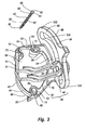
Figure 3 is a perspective view of the guide system shown inFigure 2 ; -
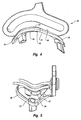
Figure 4 is an elevated left side view of the guide system shown inFigure 3 ; -
Figure 5 is an elevated front view of the guide system shown inFigure 3 ; -
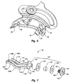
Figure 6 is a bottom perspective view of the guide system shown inFigure 3 ; -
Figure 7 is an exploded view of the guide of the guide system shown inFigure 3 ; -
Figure 8 is a perspective view of the complete milling system mounted on the femur ofFigure 1 ; -
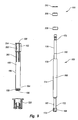
Figure 9 is a disassembled view of the mill assembly of the milling system shown inFigure 8 ; -
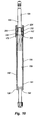
Figure 10 is a cross sectional side view of the mill assembly shown inFigure 9 ; -
Figure 11 is a bottom perspective view of the retainer of the mill assembly shown inFigure 9 ; -
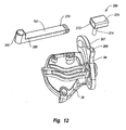
Figure 12 is a disassembled perspective view of the guide system, brace, and shackle of the milling system shown inFigure 8 ; -
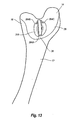
Figure 13 is a perspective view of the femur shown inFigure 1 having an incompleted pocket formed thereon by the milling assembly shown inFigure 8 ; -
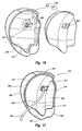
Figure 14 is a perspective view of the femur shown inFigure 13 having the completed pocket formed thereon; -
Figure 15 is a top perspective view of a trochlear implant; -
Figure 16 is a bottom perspective exploded view of the implant shown inFigure 15 ; -
Figure 17 is a bottom perspective view of the implant shown inFigure 15 having a line coupled therewith; -
Figure 18 is a cross sectional side view of the implant shown inFigure 15 along line 18-18; and -
Figure 19 is a perspective view of the femur shown inFigure 14 having the implant ofFigure 16 mounted in the pocket thereof. - The present invention relates to milling systems and related guides and mills for use in resecting an articulation surface of an orthopedic joint so that an implant can be mounted on the resected surface. As used in the specification and appended claims, the term "articulation surface" is broadly intended to include all surfaces of natural articular cartilage forming a portion of an orthopedic joint and all articulation wear surfaces of a bone forming a portion of an orthopedic joint that, as a result of wear, trauma, disease or other causes, has all or a portion of the natural articular cartilage removed.
- In the below illustrated embodiment of the present invention, milling systems and related guides and mills are shown which are specifically designed for mounting a trochlear groove implant at the distal end of a femur. It is appreciated, however, that the illustrated embodiments are simply examples of the present invention and that the same technology can also be used for resecting a portion of the articulation surface at a different location on the same articulation surface or on a variety of other joint surfaces to receive a variety of other different types of implants. By way of example and not by limitation, the present invention can be used for resecting all or a portion of a condyle and then mounting a unicondylar or partial implant. The present invention can also be used for resurfacing an articulation surface of a knee joint, ankle joint, hip joint, shoulder joint, elbow joint, wrist joint, interfrangial joint, or other joints. As such, the milling systems of the present invention can be used for preparing the articulation surface at the proximal or distal end of the femur, tibia, humors, radius, and ulna and on other articulation surfaces of the scapula, pelvis, bones within the foot and hand, and other bone articulation surfaces.
- Depicted in
Figure 1 is adistal end 10 of afemur 12.Distal end 10 has amedial side 14 and alateral side 16 that each extend between ananterior side 18 and aposterior side 20.Distal end 10 offemur 12 terminates at amedial condyle 22 and alateral condyle 24 with atrochlear groove 26 disposed therebetween.Articular cartilage 28 defines an articulation surface fordistal end 10 offemur 12.Articular cartilage 28 terminates at amargin 30. -
Trochlear groove 26 is a channel that guides the movement of the patella as the knee flexes. On occasion, due to arthritis, disease, trauma, or the like, it is necessary to replace a portion of the femur forming the trochlear groove. In the depicted embodiment of the present invention, the illustrated milling system and related guides and mills are designed to form a recessed pocket onfemur 12 at the location oftrochlear groove 26 so that an implant can be mounted within the recessed pocket. - Depicted in
Figure 2 , is aguide system 36 mounted ondistal end 10 offemur 12 overtrochlear grove 26.Guide system 36 forms a portion of the milling system. As depicted inFigure 3 ,guide system 36 comprises atemplate 38 having aguide 40 moveably mounted thereon.Template 38 comprises anannular base 42 having atop surface 44 and an opposingbottom surface 46 that each extend between afirst end 48 and an opposingsecond end 50.Surfaces first side 52 and an opposingsecond side 54.Base 42 can also be defined in terms of having opposingside portions first end portion 33 and an opposingsecond end portion 34. - In one embodiment, as perhaps best depicted in
Figure 4 ,side portions base 42 have a substantially continuous arch extending fromfirst end 48 to opposingsecond end 50. That is,bottom surface 46 has a substantially constant concave curvature while thetop surface 44 has a substantially constant convex curvature. This configuration helps to minimize the size oftemplate 38 to facilitate the greatest ease of insertion during use. In alternative embodiments, however, one or both oftop surface 44 andbottom surface 46 can be flat or have any other desired configuration. - As depicted in
Figure 5 ,end portions base 42 have a substantially V-shaped configuration such thattemplate 38 can sit within trochlear groove 26 (Figure 1 ). In alternative embodiments, such as whentemplate 38 is used for mounting a uni- or partial- condylar implant,end portions Base 42 is typically designed so as to have a contour complementary to the contour of the portion of the bone over whichbase 42 sits during use. - Returning to
Figure 3 ,base 42 also has aninterior surface 56 which bounds anopening 58 that extends throughbase 42 betweentop surface 44 andbottom surface 46. As will be discussed below in greater detail, opening 58 generally corresponds to the size of the pocket that will be formed on the bone. It is appreciated that opening 58 can have a variety of different sizes and shapes depending on the size and location of the area to be resurfaced. In the embodiment depicted,base 42 completely encirclesopening 58. In other embodiments,base 42 can bound only a portion ofopening 58. - A plurality of hubs project from
base 42 intoopening 58. More specifically, afirst hub 60 projects frominterior surface 56 ofbase 42 atfirst end 48. Asecond hub 62 projects frominterior surface 56 ofbase 42 atfirst side 52 ofbase 42 towardsecond end 50. Similarly, athird hub 64 projects frominterior surface 56 intoopening 58 generally at the intersection betweensecond side 54 andsecond end 50. As depicted inFigure 6 , downwardly projecting from eachhub corresponding support leg base 42 off offemur 12. - Support legs 66-68 are configured so that
base 42 can be placed in a stable orientation spaced abovefemur 12. Specifically, the area surroundingtrochlear groove 26 has an irregular configuration due to the irregular configuration ofmedial condyle 22,lateral condyle 24, andtrochlear groove 26. In contrast to trying to configurebase 42 to precisely fit ontrochlear groove 26, the use of three support legs 66-68 provides a stable platform that can be easily designed to supportbase 42 in a stable fashion on a plurality of different sized and shaped femurs. - As depicted in
Figure 2 ,base 42 is supported onfemur 12 as a result ofsupport leg 68 resting againstmedial condyle 22,support leg 67 resting againstlateral condyle 24, andsupport leg 66 resting against thearticular cartilage 28 withintrochlear groove 26. In one alternative embodiment,base 42 can be sized so thatsupport leg 66 rests againstanterior surface 18 outside ofarticular cartilage 28. - In other embodiments, support legs 66-68 can be positioned at different locations on
base 42 and can have a variety of different sizes and shapes. Furthermore, fewer or more support legs can be used. For example,template 38 can be designed with two support legs so that the two support legs and a portion ofbase 42 rest directly againstfemur 12. In yet other embodiments, four or more support legs can be formed projecting frombody 42. In still other embodiments, the support legs can be eliminated andbase 42 mounted directly againstarticular cartilage 28. - In one embodiment of the present invention, means are provided for removably mounting
template 38 ontofemur 12 or some other bone. By way of example and not by limitation, extending through each hub 60-62 and each support leg 66-68 is a corresponding mountinghole Figure 3 . Although not required, in the embodiments depicted each mounting hole 70-72 has anannular shoulder 74 that radially, inwardly projects into the corresponding mounting hole at a location between the opposing ends thereof. Fasteners are designed to pass through mounting holes 70-72 and engagefemur 12 so as to securetemplate 38 tofemur 12. - In the depicted embodiment, the fasteners comprise threaded screws 80. Each
screw 80 comprises anelongated shaft 82 having afirst end 84 and an opposingsecond end 86.Threads 88 are formed alongshaft 82 while anenlarged head 90 is formed atfirst end 84. In the embodiment depicted,enlarged head 90 comprises aflange 91 that encircles and radially outwardly projects fromfirst end 84. Anengagement head 92 extends aboveflange 91 and has a polygonal or non-circular cross section so that a driver can be connected toengagement head 92 for selective rotation ofscrews 80. - It is appreciated that
enlarged head 90 can be formed with a socket, slot(s), or other engaging surfaces to engage with other types of drivers. Eachscrew 80 is configured so thatsecond end 86 can be received within and slid through a corresponding mounting hole 70-72 oftemplate 38.Flange 91 is larger thanannular shoulder 74 within mounting holes 70-72 so thatflange 91 seats againstshoulder 74. - One of the benefits of having mounting holes 70-72 extend through support legs 66-68 is that support legs 66-68 function as guides during placement of the fasteners. In alternative embodiments, however, it is appreciated that other numbers of mounting holes and fasteners can be used and that mounting holes 70-72 need not extend through legs 66-68. For example, two mounting holes or four or more mounting holes can be formed through
base 42 at locations spaced apart from support legs 66-68. In other alternative embodiments, support legs 66-68 can be eliminated and the fasteners can be used to independently suspendtemplate 38 off offemur 12. In this embodiment, tubular guide sleeves can be passed through the -mounting hole to help facilitate alignment of the fasteners. In yet other alternative embodiments, screws 80 can be replaced with other conventional forms of fasteners such as bone anchors, expansion bolts, barbed shafts, and the like. - As also depicted in
Figure 3 ,template 38 further comprises abracket 94 that upwardly projects from and extends along the length ofsecond side 54 ofbase 42.Bracket 94 has aninterior face 96 and opposingexterior face 98 that each extend between afirst end 100 and an opposingsecond end 102. Anelongated guide slot 104 passes throughbracket 94 betweenfaces first end 100 andsecond end 102. In the embodiment depicted,guide slot 104 is arched along the length thereof. -
Guide 40 is movably coupled withbracket 94. Specifically, as depicted inFigure 7 , guide 40 comprises acarriage 110 having a pair of spaced apartarms Carriage 110 comprises disc shapedbase 116 having anoutside face 118 and opposing insideface 120. Atubular stem 122 projects frominside face 120 and is configured to be received withinslot 104 ofbracket 94. A threadedpassage 124 extends into or throughstem 122 andbase 116.Carriage 110 further includes anenlarged head 140 having aninside face 142 and an opposingoutside face 144. A threadedshaft 128 projects frominside face 142 and is configured to threadedly mate withpassage 124. Apolygonal recess 130 is formed onoutside face 144 and is designed to mate with some form of driver. In alternative embodiments,recess 130 can have any desired configuration to mate with other types of drivers. - During assembly, stem 122 is passed into
slot 104 ofbracket 94 while threadedshaft 128 is threaded intostem 122 from the opposing side ofbracket 94. With reference toFigures 3 and7 , by threadingshaft 128 intostem 122,base 116 andhead 140 are fixed on opposing sides ofbracket 94 so as to securecarriage 110 tobracket 94. There is sufficient play betweencarriage 110 andbracket 94 so thatcarriage 110 can freely slide along the length ofguide slot 104 without creating unwanted slop betweencarriage 110 andbracket 94. To facilitate smooth and easy sliding ofguide 40 alongguide slot 104, atubular bearing 134 can be positioned overstem 122 so as to ride against the interior surface ofbracket 94bounding slot 104. Bearing 134 can comprise a sleeve made of low friction material such as Delrin. Other materials or types of bearing, such as ball bearings or roller bearings, can also be used. Furthermore, athrust bearing 136 can be positioned overstem 122 so as to be disposed betweeninside face 120 ofbase 116 and inside face 96 ofbracket 94. Likewise, athrust bearing 138 can be placed over threadedshaft 128 so as to be positioned betweeninside face 142 ofhead 140 andoutside face 98 ofbracket 94.Thrust bearings - In the embodiment depicted,
first arm 112 ofguide 40 comprises an elongatedupper rail 146A and an elongatedlower rail 148A which are spaced apart so as to form anelongated guide slot 149 therebetween. Eachrail first end 150 connected to base 116 and an opposingsecond end 152.Second end 152 ofsecond rail 148A projects farther out thansecond end 152 offirst rail 146A.Second arm 114 is spaced apart from but has substantially the same configuration asfirst arm 112. As such,second arm 114 also includes an elongatedupper rail 146B and a spaced apart, elongatedlower rail 148B that each project frombase 116 and that have aguide slot 149 formed therebetween.Lower rails 148A and B are connected together atsecond end 152 thereof. - As depicted in
Figure 2 , during initial placement oftemplate 38, a threadedend 76 of anelongated handle 77 is threaded into a threaded hole 78 (Figure 3 ) ontemplate 38.Handle 77 can then be used for easy placement and movement oftemplate 38. Other conventional fastening techniques can also be used to removablysecure handle 77 totemplate 38. - Once handle 77 is attached,
template 38 is generally aligned by sight and/or feel by placingsupport leg 68 onmedial condyle 22,support leg 67 onlateral condyle 24, and aligningsupport leg 66 withtrochlear groove 26. Furthermore,template 38 is oriented so that opening 58 is disposed over the area that is desired to be resurfaced. The area ofarticular cartilage 28 disposed within opening 58 is herein referred to as cuttingsurface 79. Slight adjustments in placement oftemplate 38 can also be made to ensure a stable positioning oftemplate 38. Oncetemplate 38 is appropriately positioned, screws 80 or other fasteners are passed through corresponding mounting holes 70-72 ontemplate 38 so as to rigidly fixtemplate 38 tofemur 12. If desired, handle 77 can then be removed fromtemplate 38 or retained in place for assisting with removal oftemplate 38. - Turning to
Figure 8 ,milling system 35 further comprises amill assembly 160 that is supported by both guide 40 and abrace 162 mounted ontemplate 38. As depicted inFigure 9 ,mill assembly 160 comprises amill 166.Mill 166 comprises ashaft 168 having aburr 169 mounted on the end thereof. Specifically,shaft 168 has afirst end 170 and an opposingsecond end 172.Burr 169 is mounted onsecond end 172 so as to radially outwardly project fromshaft 168. In alternative embodiments the sides ofburr 169 can be flush with the side ofshaft 168.Burr 169 is comprised of a plurality of cuttingteeth 173 that enable burr to cut from the side and the bottom. As used in the specification and appended claims, the term "burr" is broadly intended to include any arrangement of cutting teeth or cutting surfaces that when mounted onshaft 168 can be used to cut bone whenshaft 168 is rotated. For example, in contrast to having one or more defined cutting teeth,burr 169 can also comprise a roughened surface that can grind or cut away bone. - It is appreciated that
shaft 168 can have a variety of different configurations. For reasons as will be discussed below in greater detail, in the depicted embodiment,shaft 168 comprises acentral portion 174. An engagingportion 176 extends fromcentral portion 174 tofirst end 170.First end 170 of engagingportion 176 is configured for mating with a drill or other type of driver that can rotatably spinshaft 168. Formed at the junction ofcentral portion 174 and engagingportion 176 is asupport shoulder 178. Anannular locking slot 180 is recessed on and radially encircles engagingportion 176.Shaft 168 also includes aguide portion 182 extending betweencentral portion 174 andburr 169.Guide portion 182 has a diameter smaller than the maximum diameter ofburr 169. - As depicted in
Figures 9 and10 , twoannular bearings first end 170 ofshaft 168 so as to sit againstsupport shoulder 178 ofshaft 168.Bearings clip 210 is then received within lockingslot 180 so as to retainbearings shaft 168. -
Mill assembly 160 also includes atubular sleeve 186 having aninterior surface 188 and anexterior surface 190 each extending between afirst end 192 and an opposingsecond end 194.Interior surface 188 bounds apassage 196 extending throughtubular sleeve 186 between opposing ends 192 and 194. Formed onexterior surface 190 atsecond end 194 are a plurality ofannular grooves 198.Grooves 198 encircletubular sleeve 186 and are spaced apart along the length thereof. In the depicted embodiment, twoannular grooves 198 are shown. In alternative embodiments,sleeve 186 can be provided with one annular groove or three or more. - A plurality of
slots 200 longitudinally extend throughtubular sleeve 186 atfirst end 192.Slots 200 are radially spaced apart so as to form a plurality of flexible, cantileveredfingers 202. Eachfinger 202 has a lockingbarb 204 radially, inwardly projecting frominterior surface 188 atfirst end 192. Anannular support shoulder 205 also radially, inwardly projects frominterior surface 188 of eachfinger 202 at a distance spaced apart frombarbs 204. - During assembly,
second end 172 ofshaft 168 is advanced down throughopening 196 ofsleeve 186 fromfirst end 192. Asbearings first enter passage 196,fingers 202 radially outwardly expand asbearings barbs 204. Oncebearings pass locking barbs 204,fingers 202 resiliently constrict. In turn,bearings sleeve 186 by support shoulders 205. As such,bearings shoulder 205 andbarbs 204, thereby rotatably capturingshaft 168 withintubular sleeve 186. -
Mill assembly 160 also includes aretainer 220 that is moveably mounted onsecond end 194 oftubular sleeve 186. As depicted inFigure 11 ,retainer 220 comprises acentral housing 222 having afront wall 224 and an opposingback wall 226 each extending between afirst end 228 and opposingsecond end 230.Housing 222 has aninterior surface 232 which bounds apassageway 234 extending between opposing ends 228 and 230.Front wall 224 andback wall 226 each have a pair of spaced apart slots 240 and 242 that extend therethrough fromsecond end 230.Channels front wall 224 bound a tab portion 244A offront wall 224 whilechannels back wall 226 bound atab portion 244B ofback wall 226. As will be discussed below in greater detail, posts 246A and 246B outwardly project fromtab portions 244A and 244B, respectively. - Mounted on opposing sides of
housing 222 areresilient arms arm lever portion 250 having an upper end with aflange 252 outwardly projecting thereat and an opposing lower end with acurved locking ridge 254 radially inwardly projecting thereat. A pair of spaced apart spring rails 256 extends from the lower end oflever portion 250 to an upper end of tab portions 244 within channels 240 and 242. In this configuration, by radially inwardly compressingarms flanges 252, lockingridges 254 are radially outwardly separated. In this position,second end 194 oftubular sleeve 186 can be passed down throughpassage 234 ofretainer 220. By releasingarms cause locking ridges 254 to resiliently move back towards each other so as to lock withingrooves 198 oftubular sleeve 186, thereby securingretainer 220 totubular sleeve 186. By again compressingarms tubular sleeve 186 can be moved relative toretainer 220 so that lockingridges 254 can be locked within adifferent grooves 198, thereby movingtubular sleeve 186 relative toretainer 220. - Turning to
Figure 12 , asocket 266 is formed on atop edge 267 ofbracket 94 oftemplate 38. Ashackle 268 comprises ahousing 270 having achannel 272 extending therethrough. Acylindrical post 274 projects fromhousing 270. During assembly, post 274 is received withinsocket 266 so thathousing 270 can freely rotate about the longitudinal axis ofpost 274 aspost 274 rotates withinsocket 266.Brace 162 has afirst end 278 and opposingsecond end 280.Brace 162 is slidably disposed withinchannel 272 ofshackle 268. Ahole 282 extends throughsecond end 280 ofbrace 162 and is adapted to receivetubular sleeve 186 therein such thattubular sleeve 186 can freely slide withinhole 282. - Returning to
Figure 8 , aftertemplate 38 is securely attached tofemur 12, as previously discussed,mill assembly 160 is coupled withtemplate 38 by coupling withguide 40 andbrace 162. Specifically, brace 162 havingtubular sleeve 186 slidably extending throughhole 282 is slidably positioned withinshackle 268. In addition, withretainer 220 coupled withtubular sleeve 186,posts 246A and B ofretainer 220 are slidably disposed withincorresponding guide slots 149 ofguide 40. In this configuration,mill 166 projects down through opening 58 oftemplate 38 so thatburr 169contacts cutting surface 79 offemur 12. - In the assembled configuration,
mill assembly 160 is supported byguide 40 and brace 162 at two spaced apart locations along the length ofmill assembly 160. This configuration ensures thatmill assembly 160 maintains a proper orientation relative to cuttingsurface 79 asmill 166 is moved along cuttingsurface 79. Maintaining proper orientation ofmill 166 helps ensure that the recessed pocket is formed within precise tolerances. - Once
mill assembly 160 is coupled withtemplate 38, a driver (not shown), such as a drill, is coupled withfirst end 170 ofmill 166. By activating the driver,mill 166 rapidly spins withintubular sleeve 186. Spinningburr 169contacts cutting surface 79 so as to enable resecting of cuttingsurface 79. It is appreciated that both guide 40 and brace 162 enablemill 166 to move in a controlled three dimensional pattern within opening 58 oftemplate 38. This not only enablesmill 166 to operate over the three dimensional profile of cuttingsurface 79 but is also enables the operator to form the recessed pocket so that the resected surface of the recessed pocket has a desired three dimensional profile that is optimal for receiving an implant. - Specifically, posts 246A and B of
retainer 220 travel withinguide slots 149 so as to enablemill 166 to travel between opposingsides template 38.Posts 246A and B ride againstlower rails 148A and B whileupper rails 146A and B help to secureretainer 220 betweenarms mill 166. The curved contour ofguide slots 149 also dictates the vertical travel ofmill 166. In turn, guide 40 moves alongguide slot 104 ofbracket 94 so thatmill 166 can move between the opposing ends 48 and 50 oftemplate 38. As such,mill 166 can pass over all of cuttingsurface 79.Guide portion 182 of the shaft ofmill 166 can also ride against and follow alonginterior surface 56 oftemplate 38 so as to form a clean smooth margin of the resected pocket. It is again appreciated that in this embodiment all horizontal and vertical movement ofmill 166 is guided and controlled by the configuration ofguide slots - If desired, the resection of cutting
surface 79 can be performed at stages in depth. As a result,burr 169 is not required to cut as much bone in a single pass. For example, during the initial resection, lockingridges 254 of retainer 220 (Figure 11 ) can be secured within thelower groove 198 on tubular sleeve 186 (Figure 9 ). After the first layer of bone is removed,tubular sleeve 186, and thusmill 166 withburr 169, can be lowered relative toretainer 220 by moving lockingridges 254 into the nexthigher groove 198 using the method as previously discussed. The milling process can then be repeated to remove the next layer of bone. - During the milling process, brace 162 helps to retain
mill 166 in the desired orientation without hampering movement ofmill 166. That is, as a result of the fact thatbrace 162 can freely slide into and out ofshackle 268 and can pivot aboutshackle 268,mill 166 can freely move horizontally within a plane. Furthermore, becausetubular sleeve 186 can freely slide vertically withinhole 282 ofbrace 162,mill 166 can also freely move in a vertical orientation.Brace 162, however, prevents tipping ofmill 166. - It is appreciated that the milling system of the present invention can have a variety of different configurations and embodiments. By way of example and not by limitation, it is appreciated that
guide 40 andretainer 220 function to provide guided movement ofmill 166 and that these structures can have a variety of other designs. For example,upper rails 146A and B can be eliminated;rails post 246A;arms retainer 220 to receive posts 246; and posts 246 can project directly fromtubular sleeve 186 whilearms carriage 110. - In still other embodiments, it is appreciate that there are a variety of conventional, mechanical fastening techniques that can be used and would enable
tubular member 186 to move relative to guide 40 and that would enable guide 40 to move relative tobracket 94. In likemanner brace 162 can be coupled in a variety of different techniques tobracket 94. For example, in contrast to pivoting, shackle 268 can be slidably mounted onbracket 94. It is also appreciated that the placement ofguide 40 and brace 162 can be switched. It is still further appreciate that a variety of different techniques can be used to rotatablysecure mill 166 withintubular sleeve 186. For example, the bearings can be press fit betweentubular sleeve 186 andmill 166 or a tubular cap can be screwed onto the end oftubular sleeve 186 that replaces lockingbarbs 204. It is appreciated that numerous other examples also exist for various alternatives of the present invention. - Once
mill 166 has completed removal of cuttingsurface 79,milling system 35 is removed fromfemur 12 so as to expose a partially completed recessedpocket 310. As shown inFigure 13 ,protrusions 284A-C ofarticulation surface 28 that were covered by support legs 66-68 and through which screws 80 extended, project into recessedpocket 310. The surgeon then uses a hand held mill with burr or other cutting apparatus to selectively removeprotrusions 284A-C so as to form the final recessedpocket 310, as shown inFigure 14 , in which the implant is ultimately mounted. - This technique has a number of benefits. For example, the only portion of
template 38 that contactsarticular cartilage 28 are support legs 66-68. It is possible that during the mounting and/or milling process that support legs 66-68 could damage the area ofarticular cartilage 28 against which support legs 66-68 sit, i.e.,protrusions 284A-C. Becauseprotrusions 284A-C are ultimately removed by resection, however, any damage to the surface area ofprotrusion 284A-C is irrelevant. Furthermore, in this embodiment the holes formed byscrews 80 are retained within thefinal recess pocket 310 and covered by the implant. As such, any potential damage made by the screws is also irrelevant. - As depicted in
Figure 14 ,pocket 310 is bounded by afloor 312 having anencircling side wall 314 upstanding around the perimeter thereof.Pocket 310 has opposingsides proximal end 320 and an opposingdistal end 322. Due to the controlled movement ofmill 166, a rounded,elongated channel 324 is recessed alongfloor 312 in substantial alignment with wheretrochlear groove 26 was previously disposed. That is,channel 324 extends between opposing ends 320 and 322.Floor 312 also has a convex curvature that extends between opposing ends 320 and 322. As will be discussed below in greater detail, the configuration of recessedpocket 310 enables the formation of a low profile trochlear implant having substantially uniform thickness. Furthermore, the formation ofpocket 310 produces a stable platform for the implant having a complementary configuration. - Once recessed
pocket 310 is finished, atunnel 330 is formed extending frompocket 310 to a location spaced apart from thearticular cartilage 28, such asmedial side 14 orlateral side 16 offemur 12.Tunnel 330 can be formed by simply using a drill to manually form the tunnel. That is,tunnel 330 can be drilled by starting at recessedpocket 310 and extending to the lateral or medial side of thefemur 12. - Once
tunnel 330 is formed, a trochlear implant is then secured within the recessedpocket 310. Depicted inFigures 15 and16 is an example of atrochlear implant 340.Trochlear implant 340 comprises abody 342 having anarticular surface 344 and an opposingbottom surface 346 that each extend to aperimeter edge 348.Body 342 is further defined as having aproximal end 350 and adistal end 352 each extending between alateral side 354 and amedial side 356.Articular surface 344 is formed having anelongated channel 376 extending betweenproximal end 350 anddistal end 352 substantially centrally betweensides Channel 376 forms at least a portion of the resurfaced trochlear groove in which the patella rides. - In one embodiment viewed in a plane extending between
sides 354 and 356 (Figure 18 ),channel 376 has a bottom 378 with a concave curvature. The surfaces extending from the concave curvature atbottom 378 toperimeter edge 348 at eachside articular surface 344 has a smooth continuous convex curvature that extends between opposing ends 350 and 352 (Figure 15 ). - Depicted in
Figure 17 , aflexible line 360 is secured totrochlear implant 340. The term "line" is broadly intended to include wire, cable, cord, suture, braded line, combinations thereof or any other type of flexible filament. The line can be made of metal, alloys, synthetics, composites, or any other desired material. The line may comprise braded filaments of a cobalt chrome alloy having a diameter in a range between about 0.25 mm to about 5 mm with about 0.5 mm to about 3 mm being more common and about 0.5 mm to about 2 mm being most common. Other dimensions can also be used. The line can be of any desired length. - The line can also be defined in that for an unsupported length of line of 4 cm, the line has substantially no compressive strength. In other examples, for an unsupported length of line of 4 cm, the line fails under buckling when an axial compressive load of 0.25 Newtons (N), 1 N, 2 N, 5 N, 20 N, or 50 N is applied. That is, different lines can be used that fail under different loads. Stiffer lines can also be used.
- It is also appreciated that the line can be static or resiliently stretchable. Where the line is resiliently stretchable, the line can be comprised of a material having shape memory of pseudo elastic properties. One example of such a material is a nickel titanium alloy sold under the name Nitinol. It is appreciated that sections of the line could be replaced with a spring member such as a coiled spring or rubber or bungee type member.
- Turning to
Figure 16 , formed onbottom surface 346 ofbody 342 is apocket 358. In the example depicted, apost 362 projects from withinpocket 358. A constrictingpassage 364 extends throughpost 362 and is configured to holdflexible line 360. Specifically,line 360 is formed with an enlarged head at one end so that whenline 360 is passed throughpassage 364, the enlarged head is captured withinpassage 364. Secured withinpocket 358 is aninlay 366 of a porous bone ingrowth material.Inlay 366 has anopening 368 formed thereon through which post 362 extends. - Returning to
Figure 17 ,bottom surface 346 andinlay 366 combine to form abone apposition surface 370 oftrochlear implant 340.Bone apposition surface 370 has a configuration complementary to the formation of recessedpocket 310 formed onfemur 12.Bone apposition surface 370 also typically has a configuration complementary toarticular surface 344. Specifically,bone apposition surface 370 is formed having a rounded, outwardly projectingridge 372 that extends betweenproximal end 350 anddistal end 352, substantially centrally betweensides sides 354 and 356 (Figure 18 ),ridge 372 terminates at an apex 374 having a convex curvature. The side surfaces ofridge 372 extending tosides -
Ridge 372 is typically aligned withchannel 376 so thattrochlear implant 340 can have a substantially uniform thickness. For example,bone apposition surface 370 can be substantially complementary toarticular surface 344 so thatimplant 340 has a substantially uniform thickness betweensurfaces implant 340 may be slightly tapered alongperimeter edge 348. Thus, at all locations at least 2 mm in from theperimeter edge 348,body 342 has a thickness extending between thebone apposition surface 370 and thearticular surface 344 that does not vary by more than 30%, 20%, or more commonly 15%. Other percentages can also be used. The actual thickness depends on the desired implant and is typically in a range between about 3 mm to about 10 mm. -
Ridge 372 is also configured to be complementarity received withinchannel 324 formed on recessedpocket 310. Thus,bone apposition surface 370 also has a continuous concave curvature extending between opposing ends 350 and 352. Because of the unique method in whichpocket 310 can be formed,bone apposition surface 370 can be formed having a smooth surface with substantially no stepped shoulders or corners as required in many conventional implants. - Because
implant 340 is configured to fit withinpocket 310,implant 340 has an outer perimeter having a configuration complementary topocket 310. It is appreciated thatimplant 340 as discussed above and depicted herein is only one example of an implant that can be used. In alternative examples,implant 340 can have a variety of different sizes, shapes, configurations, components, and other modifications. For example, spikes or other forms of projections can be formed projecting frombone apposition surface 370. Furthermore, conventional implants using conventional mounting techniques can be secured withinpocked 310. - Finally, turning to
Figure 19 ,trochlear implant 340 is secured within recessedpocket 310 offemur 12. In the depicted arrangement, this is accomplished by passing line 360 (Figure 17 ) within tunnel 330 (Figure 14 ) and then using a tensioner and anchor assembly to secureline 360 withintunnel 330. Conventional techniques can be used to secure implant withinpocket 310. In such techniques,line 360 can be eliminated. - The above disclosure discusses a number of different guides, mills and other related instruments, implants and methods. It is appreciated that the individual components and subcombination of components are novel and can be used independently or mixed and matched with other conventional systems.
- Different features of the embodiments of the present invention provide a number of benefits over conventional systems and methods. For example, in contrast to many conventional processes which require the removal of an entire articulation surface for the mounting of an implant, embodiments of the present invention enable the resurfacing of an isolated location on the articulation surface. As a result, the procedure is less invasive and recovery time is decreased. The milling systems of embodiments of the present invention enable the formation of the pocket while minimizing retraction of soft tissue, minimizing the amount of bone removal, and minimizing the time required to remove the bone and mount the implant. Using a high speed burr as opposed to a saw blade or rasp also has advantages in that the burr requires less effort to cut and can more precisely remove sections of bone. Furthermore, unlike saw blades and rasps, which during use often cover a portion of the bone which is desired to be removed, burrs allow for greater visibility of the bone during removal, thereby improving accuracy of bone removal.
- The milling system is also unique in that the milling system is largely mounted only over the area of the articulation surface that is to be resurfaced. As a result, the potential for unintentional damage to the portion of the surrounding articular surface that is not to be resurfaced is minimized. Another advantage of embodiments of the present invention is that they provide a system that is easy to mount and use on uneven or irregular surfaces, is easy to operate, and is easy to remove. Embodiments of the present invention also provides other advantages which will be apparent to those skilled in the art.
Claims (7)
- A milling system for use in resecting at least a portion of a joint articulation surface of a bone, the system comprising:a template (38) comprising a base (42) having a top surface (44), an opposing bottom surface (46) with an opening extending therebetween;means for removably mounting the template (38) on a bone;a guide (40) movably mounted on the template (38) and projecting across at least a portion of the opening of the template (38), the guide (40) being selectively movable across at least a portion of the opening of the template (38); characterized in thatthe template (38) further comprises a bracket (94) projecting from the base (42) and extending along the length of the opening of the template (38), the guide (40) being coupled with and selectively movable along the length of the bracket (94) and the template further comprising at least two spaced apart support legs (66, 67, 68) projecting from the base (42) so as to extend below the bottom surface (46) anda rotatable mill (160) mounted on the guide (40), the mill being selectively movable along at least a portion of the length of the guide (40).
- The milling system as recited in claim 1, wherein the means for removably mounting the template comprises:at least three spaced apart mounting holes (70,71,72) formed on the template (38); andat least three fasteners (80), each fastener (80) being adapted to pass through a corresponding one of the mounting holes (70, 71, 72) and to engage the bone.
- The milling system as recited in claim 1, wherein the guide (40) comprises a carriage (110) coupled with the bracket (94) and a pair of spaced apart arms (112, 114) projecting from the carriage (110) and across at least a portion of opening of the template (36).
- The milling system as recited in claim 3, further comprising:a retainer (220) having a tubular sleeve (186) coupled therewith, the mill (160) being disposed within the tubular sleeve (186); andmeans for coupling the retainer (220) to the guide (40) so that the retainer (220) can selectively move along the length of the guide (40).
- The milling system as recited in claim 4, wherein the means for coupling the retainer (220) to the guide comprises:each arm (112,114) of the guide (40) having a slot (149) formed along the length thereof; anda post (246A, 246B) projecting from each side of the retainer (220), the retainer (220) being disposed between the arms of the guide (40) with each post (246A, 246B) being slidably disposed within the slot (149) of a corresponding arm (112, 114).
- The milling system as recited in claim 1, further comprising a brace (162) movably mounted on the template (38) so as to extend over a portion of the opening of the template (38), the mill (160) being supported by the brace (162).
- The milling system as recited in claim 6, further comprising a tubular sleeve (186) having a passage (196) extending therethrough, the mill (160) being rotatably disposed within the tubular sleeve (186), the tubular sleeve (186) being coupled with the brace (162).
Applications Claiming Priority (2)
| Application Number | Priority Date | Filing Date | Title |
|---|---|---|---|
| US11/138,016 US7695477B2 (en) | 2005-05-26 | 2005-05-26 | Milling system and methods for resecting a joint articulation surface |
| PCT/US2006/018117 WO2006127283A2 (en) | 2005-05-26 | 2006-05-11 | Milling system for resecting a joint articulation surface |
Publications (2)
| Publication Number | Publication Date |
|---|---|
| EP1883355A2 EP1883355A2 (en) | 2008-02-06 |
| EP1883355B1 true EP1883355B1 (en) | 2015-08-19 |
Family
ID=37074640
Family Applications (1)
| Application Number | Title | Priority Date | Filing Date |
|---|---|---|---|
| EP06752483.5A Not-in-force EP1883355B1 (en) | 2005-05-26 | 2006-05-11 | Milling system for resecting a joint articulation surface |
Country Status (5)
| Country | Link |
|---|---|
| US (1) | US7695477B2 (en) |
| EP (1) | EP1883355B1 (en) |
| JP (1) | JP2008545469A (en) |
| CA (1) | CA2605093A1 (en) |
| WO (1) | WO2006127283A2 (en) |
Families Citing this family (121)
| Publication number | Priority date | Publication date | Assignee | Title |
|---|---|---|---|---|
| US7468075B2 (en) | 2001-05-25 | 2008-12-23 | Conformis, Inc. | Methods and compositions for articular repair |
| US8083745B2 (en) | 2001-05-25 | 2011-12-27 | Conformis, Inc. | Surgical tools for arthroplasty |
| US7534263B2 (en) | 2001-05-25 | 2009-05-19 | Conformis, Inc. | Surgical tools facilitating increased accuracy, speed and simplicity in performing joint arthroplasty |
| US7239908B1 (en) | 1998-09-14 | 2007-07-03 | The Board Of Trustees Of The Leland Stanford Junior University | Assessing the condition of a joint and devising treatment |
| AU772012B2 (en) | 1998-09-14 | 2004-04-08 | Board Of Trustees Of The Leland Stanford Junior University | Assessing the condition of a joint and preventing damage |
| ATE413135T1 (en) | 2000-09-14 | 2008-11-15 | Univ Leland Stanford Junior | ASSESSMENT OF THE CONDITION OF A JOINT AND THE LOSS OF CARTILAGE TISSUE |
| US8951260B2 (en) | 2001-05-25 | 2015-02-10 | Conformis, Inc. | Surgical cutting guide |
| EP1389980B1 (en) | 2001-05-25 | 2011-04-06 | Conformis, Inc. | Methods and compositions for articular resurfacing |
| US8439926B2 (en) | 2001-05-25 | 2013-05-14 | Conformis, Inc. | Patient selectable joint arthroplasty devices and surgical tools |
| US7806898B2 (en) * | 2004-07-09 | 2010-10-05 | Zimmer, Inc. | Modular guide systems and related rasps and methods for resecting a joint articulation surface |
| US8157867B2 (en) | 2004-07-09 | 2012-04-17 | Zimmer, Inc. | Trochlear groove implants and related methods and instruments |
| WO2006127486A2 (en) * | 2005-05-20 | 2006-11-30 | Smith & Nephew, Inc. | Patello-femoral joint implant and instrumentation |
| US7727239B2 (en) * | 2005-06-10 | 2010-06-01 | Zimmer Technology, Inc. | Milling system with guide paths and related methods for resecting a joint articulation surface |
| EP1981409B1 (en) | 2006-02-06 | 2017-01-11 | ConforMIS, Inc. | Patient selectable joint arthroplasty devices and surgical tools |
| US8623026B2 (en) * | 2006-02-06 | 2014-01-07 | Conformis, Inc. | Patient selectable joint arthroplasty devices and surgical tools incorporating anatomical relief |
| US8568487B2 (en) | 2006-02-27 | 2013-10-29 | Biomet Manufacturing, Llc | Patient-specific hip joint devices |
| US8070752B2 (en) | 2006-02-27 | 2011-12-06 | Biomet Manufacturing Corp. | Patient specific alignment guide and inter-operative adjustment |
| US9339278B2 (en) | 2006-02-27 | 2016-05-17 | Biomet Manufacturing, Llc | Patient-specific acetabular guides and associated instruments |
| US9345548B2 (en) | 2006-02-27 | 2016-05-24 | Biomet Manufacturing, Llc | Patient-specific pre-operative planning |
| US8591516B2 (en) | 2006-02-27 | 2013-11-26 | Biomet Manufacturing, Llc | Patient-specific orthopedic instruments |
| US8241293B2 (en) | 2006-02-27 | 2012-08-14 | Biomet Manufacturing Corp. | Patient specific high tibia osteotomy |
| US8608748B2 (en) | 2006-02-27 | 2013-12-17 | Biomet Manufacturing, Llc | Patient specific guides |
| US8608749B2 (en) | 2006-02-27 | 2013-12-17 | Biomet Manufacturing, Llc | Patient-specific acetabular guides and associated instruments |
| US9918740B2 (en) | 2006-02-27 | 2018-03-20 | Biomet Manufacturing, Llc | Backup surgical instrument system and method |
| US8133234B2 (en) | 2006-02-27 | 2012-03-13 | Biomet Manufacturing Corp. | Patient specific acetabular guide and method |
| US20150335438A1 (en) | 2006-02-27 | 2015-11-26 | Biomet Manufacturing, Llc. | Patient-specific augments |
| US9113971B2 (en) | 2006-02-27 | 2015-08-25 | Biomet Manufacturing, Llc | Femoral acetabular impingement guide |
| US9289253B2 (en) | 2006-02-27 | 2016-03-22 | Biomet Manufacturing, Llc | Patient-specific shoulder guide |
| US8377066B2 (en) * | 2006-02-27 | 2013-02-19 | Biomet Manufacturing Corp. | Patient-specific elbow guides and associated methods |
| US8864769B2 (en) | 2006-02-27 | 2014-10-21 | Biomet Manufacturing, Llc | Alignment guides with patient-specific anchoring elements |
| US8535387B2 (en) | 2006-02-27 | 2013-09-17 | Biomet Manufacturing, Llc | Patient-specific tools and implants |
| US8407067B2 (en) | 2007-04-17 | 2013-03-26 | Biomet Manufacturing Corp. | Method and apparatus for manufacturing an implant |
| US8473305B2 (en) | 2007-04-17 | 2013-06-25 | Biomet Manufacturing Corp. | Method and apparatus for manufacturing an implant |
| US7967868B2 (en) | 2007-04-17 | 2011-06-28 | Biomet Manufacturing Corp. | Patient-modified implant and associated method |
| US8298237B2 (en) | 2006-06-09 | 2012-10-30 | Biomet Manufacturing Corp. | Patient-specific alignment guide for multiple incisions |
| US10278711B2 (en) | 2006-02-27 | 2019-05-07 | Biomet Manufacturing, Llc | Patient-specific femoral guide |
| US8603180B2 (en) | 2006-02-27 | 2013-12-10 | Biomet Manufacturing, Llc | Patient-specific acetabular alignment guides |
| US9907659B2 (en) | 2007-04-17 | 2018-03-06 | Biomet Manufacturing, Llc | Method and apparatus for manufacturing an implant |
| US8092465B2 (en) | 2006-06-09 | 2012-01-10 | Biomet Manufacturing Corp. | Patient specific knee alignment guide and associated method |
| US8858561B2 (en) | 2006-06-09 | 2014-10-14 | Blomet Manufacturing, LLC | Patient-specific alignment guide |
| US9173661B2 (en) | 2006-02-27 | 2015-11-03 | Biomet Manufacturing, Llc | Patient specific alignment guide with cutting surface and laser indicator |
| US8282646B2 (en) | 2006-02-27 | 2012-10-09 | Biomet Manufacturing Corp. | Patient specific knee alignment guide and associated method |
| US9795399B2 (en) | 2006-06-09 | 2017-10-24 | Biomet Manufacturing, Llc | Patient-specific knee alignment guide and associated method |
| US7678115B2 (en) * | 2006-06-21 | 2010-03-16 | Howmedia Osteonics Corp. | Unicondylar knee implants and insertion methods therefor |
| US20080183176A1 (en) * | 2007-01-26 | 2008-07-31 | Howmedica Osteonics Corp. | Linked tibial resection guide |
| WO2008112996A1 (en) * | 2007-03-14 | 2008-09-18 | Conformis, Inc. | Surgical tools for arthroplasty |
| US8265949B2 (en) | 2007-09-27 | 2012-09-11 | Depuy Products, Inc. | Customized patient surgical plan |
| ES2802126T3 (en) | 2007-09-30 | 2021-01-15 | Depuy Products Inc | Patient Specific Custom Orthopedic Surgical Instrument |
| US8357111B2 (en) | 2007-09-30 | 2013-01-22 | Depuy Products, Inc. | Method and system for designing patient-specific orthopaedic surgical instruments |
| GB0813659D0 (en) | 2008-07-25 | 2008-09-03 | Smith & Nephew | Fracture putty |
| WO2010014808A2 (en) * | 2008-08-01 | 2010-02-04 | Depuy Products, Inc. | Orthopaedic surgical instrumentation and method for performing a patellofemoral arthroplasty procedure |
| US8562608B2 (en) | 2008-09-19 | 2013-10-22 | Zimmer, Inc. | Patello-femoral milling system |
| JP2012504470A (en) * | 2008-10-02 | 2012-02-23 | マコ サージカル コーポレーション | Artificial joint device for knee joint and method for transplantation and removal thereof |
| US8170641B2 (en) | 2009-02-20 | 2012-05-01 | Biomet Manufacturing Corp. | Method of imaging an extremity of a patient |
| US8808303B2 (en) | 2009-02-24 | 2014-08-19 | Microport Orthopedics Holdings Inc. | Orthopedic surgical guide |
| US9017334B2 (en) | 2009-02-24 | 2015-04-28 | Microport Orthopedics Holdings Inc. | Patient specific surgical guide locator and mount |
| US8808297B2 (en) | 2009-02-24 | 2014-08-19 | Microport Orthopedics Holdings Inc. | Orthopedic surgical guide |
| US20100222782A1 (en) * | 2009-02-27 | 2010-09-02 | Howmedica Osteonics Corp. | Spot facing trochlear groove |
| US8480753B2 (en) | 2009-02-27 | 2013-07-09 | Howmedica Osteonics Corp. | Spot facing trochlear groove |
| BRPI1014917A2 (en) | 2009-04-16 | 2016-04-19 | Conformis Inc | "Patient specific joint arthroplasty devices for ligament repair" |
| DE102009028503B4 (en) | 2009-08-13 | 2013-11-14 | Biomet Manufacturing Corp. | Resection template for the resection of bones, method for producing such a resection template and operation set for performing knee joint surgery |
| EP2493396B1 (en) * | 2009-10-29 | 2016-11-23 | Zimmer, Inc. | Patient-specific mill guide |
| US8632547B2 (en) | 2010-02-26 | 2014-01-21 | Biomet Sports Medicine, Llc | Patient-specific osteotomy devices and methods |
| US9066727B2 (en) | 2010-03-04 | 2015-06-30 | Materialise Nv | Patient-specific computed tomography guides |
| US9271840B2 (en) | 2010-03-10 | 2016-03-01 | John Keggi | Low stress all poly tibial component |
| US9579106B2 (en) | 2010-03-31 | 2017-02-28 | New York Society For The Relief Of The Ruptured And Crippled, Maintaining The Hospital For Special Surgery | Shoulder arthroplasty instrumentation |
| CA2802190A1 (en) | 2010-06-11 | 2011-12-15 | Smith & Nephew, Inc. | Patient-matched instruments |
| US9301846B2 (en) | 2010-08-13 | 2016-04-05 | Smith & Nephew, Inc. | Instruments for knee placement |
| WO2012027402A2 (en) * | 2010-08-23 | 2012-03-01 | Luke Andrew Gibson | Patient-matched instruments |
| US8617170B2 (en) | 2010-09-29 | 2013-12-31 | DePuy Synthes Products, LLC | Customized patient-specific computer controlled cutting system and method |
| US9271744B2 (en) | 2010-09-29 | 2016-03-01 | Biomet Manufacturing, Llc | Patient-specific guide for partial acetabular socket replacement |
| US20120089146A1 (en) | 2010-10-06 | 2012-04-12 | Howmedica Osteonics Corp. | System and method of bone preparation |
| US9968376B2 (en) | 2010-11-29 | 2018-05-15 | Biomet Manufacturing, Llc | Patient-specific orthopedic instruments |
| US9241745B2 (en) | 2011-03-07 | 2016-01-26 | Biomet Manufacturing, Llc | Patient-specific femoral version guide |
| US8715289B2 (en) | 2011-04-15 | 2014-05-06 | Biomet Manufacturing, Llc | Patient-specific numerically controlled instrument |
| US9675400B2 (en) | 2011-04-19 | 2017-06-13 | Biomet Manufacturing, Llc | Patient-specific fracture fixation instrumentation and method |
| US8668700B2 (en) | 2011-04-29 | 2014-03-11 | Biomet Manufacturing, Llc | Patient-specific convertible guides |
| US8956364B2 (en) | 2011-04-29 | 2015-02-17 | Biomet Manufacturing, Llc | Patient-specific partial knee guides and other instruments |
| US8532807B2 (en) | 2011-06-06 | 2013-09-10 | Biomet Manufacturing, Llc | Pre-operative planning and manufacturing method for orthopedic procedure |
| US9084618B2 (en) | 2011-06-13 | 2015-07-21 | Biomet Manufacturing, Llc | Drill guides for confirming alignment of patient-specific alignment guides |
| US8529574B2 (en) | 2011-06-22 | 2013-09-10 | Howmedica Osteonics Corp. | Cutting guide for removal of cam lesion |
| US20130001121A1 (en) | 2011-07-01 | 2013-01-03 | Biomet Manufacturing Corp. | Backup kit for a patient-specific arthroplasty kit assembly |
| US8764760B2 (en) | 2011-07-01 | 2014-07-01 | Biomet Manufacturing, Llc | Patient-specific bone-cutting guidance instruments and methods |
| US8597365B2 (en) | 2011-08-04 | 2013-12-03 | Biomet Manufacturing, Llc | Patient-specific pelvic implants for acetabular reconstruction |
| US9066734B2 (en) | 2011-08-31 | 2015-06-30 | Biomet Manufacturing, Llc | Patient-specific sacroiliac guides and associated methods |
| US9295497B2 (en) | 2011-08-31 | 2016-03-29 | Biomet Manufacturing, Llc | Patient-specific sacroiliac and pedicle guides |
| US9386993B2 (en) | 2011-09-29 | 2016-07-12 | Biomet Manufacturing, Llc | Patient-specific femoroacetabular impingement instruments and methods |
| KR20130046337A (en) | 2011-10-27 | 2013-05-07 | 삼성전자주식회사 | Multi-view device and contol method thereof, display apparatus and contol method thereof, and display system |
| US9451973B2 (en) | 2011-10-27 | 2016-09-27 | Biomet Manufacturing, Llc | Patient specific glenoid guide |
| US9301812B2 (en) | 2011-10-27 | 2016-04-05 | Biomet Manufacturing, Llc | Methods for patient-specific shoulder arthroplasty |
| US9554910B2 (en) | 2011-10-27 | 2017-01-31 | Biomet Manufacturing, Llc | Patient-specific glenoid guide and implants |
| WO2013062848A1 (en) | 2011-10-27 | 2013-05-02 | Biomet Manufacturing Corporation | Patient-specific glenoid guides |
| US9237950B2 (en) | 2012-02-02 | 2016-01-19 | Biomet Manufacturing, Llc | Implant with patient-specific porous structure |
| US9486226B2 (en) | 2012-04-18 | 2016-11-08 | Conformis, Inc. | Tibial guides, tools, and techniques for resecting the tibial plateau |
| US9675471B2 (en) | 2012-06-11 | 2017-06-13 | Conformis, Inc. | Devices, techniques and methods for assessing joint spacing, balancing soft tissues and obtaining desired kinematics for joint implant components |
| US20150223941A1 (en) * | 2012-08-27 | 2015-08-13 | Conformis, Inc. | Methods, Devices and Techniques for Improved Placement and Fixation of Shoulder Implant Components |
| US9204977B2 (en) | 2012-12-11 | 2015-12-08 | Biomet Manufacturing, Llc | Patient-specific acetabular guide for anterior approach |
| US9060788B2 (en) | 2012-12-11 | 2015-06-23 | Biomet Manufacturing, Llc | Patient-specific acetabular guide for anterior approach |
| US9289222B2 (en) | 2013-02-01 | 2016-03-22 | Biomet Sports Medicine, Llc | Apparatus and method for repairing bone defects |
| EP2774555A1 (en) * | 2013-03-05 | 2014-09-10 | WALDEMAR LINK GmbH & Co. KG | Medical tool system |
| US9427334B2 (en) * | 2013-03-08 | 2016-08-30 | Stryker Corporation | Bone pads |
| US9839438B2 (en) | 2013-03-11 | 2017-12-12 | Biomet Manufacturing, Llc | Patient-specific glenoid guide with a reusable guide holder |
| US9579107B2 (en) | 2013-03-12 | 2017-02-28 | Biomet Manufacturing, Llc | Multi-point fit for patient specific guide |
| US9498233B2 (en) | 2013-03-13 | 2016-11-22 | Biomet Manufacturing, Llc. | Universal acetabular guide and associated hardware |
| US9826981B2 (en) | 2013-03-13 | 2017-11-28 | Biomet Manufacturing, Llc | Tangential fit of patient-specific guides |
| US9517145B2 (en) | 2013-03-15 | 2016-12-13 | Biomet Manufacturing, Llc | Guide alignment system and method |
| US20150112349A1 (en) | 2013-10-21 | 2015-04-23 | Biomet Manufacturing, Llc | Ligament Guide Registration |
| US9655727B2 (en) | 2013-12-12 | 2017-05-23 | Stryker Corporation | Extended patellofemoral |
| US10282488B2 (en) | 2014-04-25 | 2019-05-07 | Biomet Manufacturing, Llc | HTO guide with optional guided ACL/PCL tunnels |
| US9408616B2 (en) | 2014-05-12 | 2016-08-09 | Biomet Manufacturing, Llc | Humeral cut guide |
| US9561040B2 (en) | 2014-06-03 | 2017-02-07 | Biomet Manufacturing, Llc | Patient-specific glenoid depth control |
| US9839436B2 (en) | 2014-06-03 | 2017-12-12 | Biomet Manufacturing, Llc | Patient-specific glenoid depth control |
| US9833245B2 (en) | 2014-09-29 | 2017-12-05 | Biomet Sports Medicine, Llc | Tibial tubercule osteotomy |
| US9826994B2 (en) | 2014-09-29 | 2017-11-28 | Biomet Manufacturing, Llc | Adjustable glenoid pin insertion guide |
| US9820868B2 (en) | 2015-03-30 | 2017-11-21 | Biomet Manufacturing, Llc | Method and apparatus for a pin apparatus |
| US10568647B2 (en) | 2015-06-25 | 2020-02-25 | Biomet Manufacturing, Llc | Patient-specific humeral guide designs |
| US10226262B2 (en) | 2015-06-25 | 2019-03-12 | Biomet Manufacturing, Llc | Patient-specific humeral guide designs |
| US9999428B2 (en) * | 2015-06-30 | 2018-06-19 | DePuy Synthes Products, Inc. | Orthopaedic surgical instrument system and method for surgically preparing a patients bone |
| US10722310B2 (en) | 2017-03-13 | 2020-07-28 | Zimmer Biomet CMF and Thoracic, LLC | Virtual surgery planning system and method |
| WO2018213094A1 (en) * | 2017-05-19 | 2018-11-22 | Biomet Manufacturing, Llc | Implant assembly tools |
| US11051829B2 (en) | 2018-06-26 | 2021-07-06 | DePuy Synthes Products, Inc. | Customized patient-specific orthopaedic surgical instrument |
Family Cites Families (51)
| Publication number | Priority date | Publication date | Assignee | Title |
|---|---|---|---|---|
| GB1360485A (en) * | 1971-04-21 | 1974-07-17 | Helfet Arthur Jacob | Replacements for bicondylar joints in natural or artificial human limbs |
| US4964868A (en) * | 1985-07-25 | 1990-10-23 | Harrington Arthritis Research Center | Knee prosthesis |
| US4719908A (en) * | 1986-08-15 | 1988-01-19 | Osteonics Corp. | Method and apparatus for implanting a prosthetic device |
| SE468199B (en) * | 1988-04-11 | 1992-11-23 | Astra Ab | KNAELEDSPROTES |
| GR1000872B (en) | 1989-10-31 | 1993-03-16 | Konstantinos Protogirou | The anchorage of hip and knee protheses with the use of prestressing and the insertion of joint (an articulation) |
| US5035699A (en) * | 1990-01-09 | 1991-07-30 | Dow Corning Wright | Patella track cutter and guide |
| US5100409A (en) * | 1991-03-07 | 1992-03-31 | Dow Corning Wright Corporation | Shaping and trial reduction guide for implantation of femoral prosthesis and method of using same |
| FR2682589B1 (en) | 1991-10-16 | 1994-04-01 | Laboureau Jacques Philippe | TROCHLEEN ELEMENT FOR PROSTHESIS OF FEMORO-PATELLAR BALL JOINT. |
| DE4141153A1 (en) * | 1991-12-13 | 1993-06-17 | Pennig Dietmar | GUIDE DEVICE FOR INSERTING A LEG SCREW |
| US5344423A (en) * | 1992-02-06 | 1994-09-06 | Zimmer, Inc. | Apparatus and method for milling bone |
| US5176684A (en) * | 1992-02-20 | 1993-01-05 | Dow Corning Wright | Modular shaping and trial reduction guide for implantation of posterior-stabilized femoral prosthesis and method of using same |
| US5417695A (en) * | 1992-07-27 | 1995-05-23 | Pfizer Hospital Products Group, Inc. | Instrumentation for preparing a distal femur |
| US5312408A (en) * | 1992-10-21 | 1994-05-17 | Brown Byron L | Apparatus and method of cutting and suctioning the medullary canal of long bones prior to insertion of an endoprosthesis |
| USD357315S (en) * | 1993-03-15 | 1995-04-11 | Zimmer, Inc. | Bone milling template |
| US5334205A (en) * | 1993-06-30 | 1994-08-02 | The United States Of America As Represented By The Secretary Of The Air Force | Sacroiliac joint fixation guide |
| US5474559A (en) * | 1993-07-06 | 1995-12-12 | Zimmer, Inc. | Femoral milling instrumentation for use in total knee arthroplasty with optional cutting guide attachment |
| CA2126627C (en) * | 1993-07-06 | 2005-01-25 | Kim C. Bertin | Femoral milling instrumentation for use in total knee arthroplasty with optional cutting guide attachment |
| US5413606A (en) * | 1993-08-09 | 1995-05-09 | Fisk; Albert W. | Intraoperative method of restoring the surface smoothness of total knee replacement components |
| US5908424A (en) * | 1994-05-16 | 1999-06-01 | Zimmer, Inc, By Said Stalcup, Dietz, Bays And Vanlaningham | Tibial milling guide system |
| US5484446A (en) * | 1994-06-27 | 1996-01-16 | Zimmer, Inc. | Alignment guide for use in orthopaedic surgery |
| USD376202S (en) * | 1994-07-11 | 1996-12-03 | Zimmer, Inc. | Orthopaedic bone cutting guide |
| US5755803A (en) * | 1994-09-02 | 1998-05-26 | Hudson Surgical Design | Prosthetic implant |
| US5609642A (en) * | 1995-02-15 | 1997-03-11 | Smith & Nephew Richards Inc. | Tibial trial prosthesis and bone preparation system |
| US5634927A (en) * | 1995-07-06 | 1997-06-03 | Zimmer, Inc. | Sizing plate and drill guide assembly for orthopaedic knee instrumentation |
| US5709689A (en) * | 1995-09-25 | 1998-01-20 | Wright Medical Technology, Inc. | Distal femur multiple resection guide |
| US5653714A (en) * | 1996-02-22 | 1997-08-05 | Zimmer, Inc. | Dual slide cutting guide |
| US5885035A (en) * | 1996-03-04 | 1999-03-23 | Mtf, Inc. | Trowel filer |
| US6159214A (en) | 1996-07-31 | 2000-12-12 | Michelson; Gary K. | Milling instrumentation and method for preparing a space between adjacent vertebral bodies |
| GB9715440D0 (en) * | 1997-07-22 | 1997-09-24 | Dall Desmond Meiring | Bone grip |
| US6344043B1 (en) * | 1997-11-18 | 2002-02-05 | Michael J. Pappas | Anterior-posterior femoral resection guide with set of detachable collets |
| US6159216A (en) * | 1998-09-09 | 2000-12-12 | Sulzer Orthopedics Inc. | Combination tibial preparation instrumentation |
| US6132468A (en) * | 1998-09-10 | 2000-10-17 | Mansmann; Kevin A. | Arthroscopic replacement of cartilage using flexible inflatable envelopes |
| US6063091A (en) * | 1998-10-13 | 2000-05-16 | Stryker Technologies Corporation | Methods and tools for tibial intermedullary revision surgery and associated tibial components |
| US6436101B1 (en) * | 1999-10-13 | 2002-08-20 | James S. Hamada | Rasp for use in spine surgery |
| US6764491B2 (en) * | 1999-10-21 | 2004-07-20 | Sdgi Holdings, Inc. | Devices and techniques for a posterior lateral disc space approach |
| US7104996B2 (en) * | 2000-01-14 | 2006-09-12 | Marctec. Llc | Method of performing surgery |
| CA2402326A1 (en) * | 2000-03-10 | 2001-09-13 | Smith & Nephew, Inc. | Apparatus for use in arthroplasty of the knees |
| US6355045B1 (en) * | 2000-12-28 | 2002-03-12 | Depuy Orthopaedics, Inc. | Method and apparatus for surgically preparing a tibia for implantation of a prosthetic implant component which has an offset stem |
| US6554838B2 (en) * | 2001-05-31 | 2003-04-29 | Howmedica Osteonics Corp. | Method and apparatus for implanting a prosthetic device |
| US6482209B1 (en) * | 2001-06-14 | 2002-11-19 | Gerard A. Engh | Apparatus and method for sculpting the surface of a joint |
| FR2826254B1 (en) * | 2001-06-25 | 2004-06-18 | Aesculap Sa | DEVICE FOR POSITIONING A CUTTING PLAN OF A BONE CUTTING GUIDE |
| US7922772B2 (en) * | 2002-05-24 | 2011-04-12 | Zimmer, Inc. | Implants and related methods and apparatus for securing an implant on an articulating surface of an orthopedic joint |
| US7771483B2 (en) * | 2003-12-30 | 2010-08-10 | Zimmer, Inc. | Tibial condylar hemiplasty implants, anchor assemblies, and related methods |
| US7083625B2 (en) | 2002-06-28 | 2006-08-01 | Sdgi Holdings, Inc. | Instruments and techniques for spinal disc space preparation |
| FR2856268B1 (en) * | 2003-06-18 | 2005-10-21 | Perception Raisonnement Action | BONE CUTTING GUIDING DEVICE |
| US7867236B2 (en) * | 2003-12-30 | 2011-01-11 | Zimmer, Inc. | Instruments and methods for preparing a joint articulation surface for an implant |
| US7544209B2 (en) | 2004-01-12 | 2009-06-09 | Lotke Paul A | Patello-femoral prosthesis |
| US20050192588A1 (en) * | 2004-02-27 | 2005-09-01 | Garcia Daniel X. | Instrumentation and method for prosthetic knee |
| US8157867B2 (en) * | 2004-07-09 | 2012-04-17 | Zimmer, Inc. | Trochlear groove implants and related methods and instruments |
| US7806898B2 (en) * | 2004-07-09 | 2010-10-05 | Zimmer, Inc. | Modular guide systems and related rasps and methods for resecting a joint articulation surface |
| US7727239B2 (en) * | 2005-06-10 | 2010-06-01 | Zimmer Technology, Inc. | Milling system with guide paths and related methods for resecting a joint articulation surface |
-
2005
- 2005-05-26 US US11/138,016 patent/US7695477B2/en not_active Expired - Fee Related
-
2006
- 2006-05-11 CA CA002605093A patent/CA2605093A1/en not_active Abandoned
- 2006-05-11 JP JP2008513520A patent/JP2008545469A/en active Pending
- 2006-05-11 EP EP06752483.5A patent/EP1883355B1/en not_active Not-in-force
- 2006-05-11 WO PCT/US2006/018117 patent/WO2006127283A2/en active Application Filing
Also Published As
| Publication number | Publication date |
|---|---|
| WO2006127283A3 (en) | 2007-05-03 |
| US7695477B2 (en) | 2010-04-13 |
| WO2006127283A2 (en) | 2006-11-30 |
| CA2605093A1 (en) | 2006-11-30 |
| JP2008545469A (en) | 2008-12-18 |
| EP1883355A2 (en) | 2008-02-06 |
| US20060276796A1 (en) | 2006-12-07 |
Similar Documents
| Publication | Publication Date | Title |
|---|---|---|
| EP1883355B1 (en) | Milling system for resecting a joint articulation surface | |
| US7727239B2 (en) | Milling system with guide paths and related methods for resecting a joint articulation surface | |
| US7806898B2 (en) | Modular guide systems and related rasps and methods for resecting a joint articulation surface | |
| US8852195B2 (en) | Guide templates for surgical implants and related methods | |
| JP3217426B2 (en) | Modular guide for femoral cutting | |
| EP1838224B1 (en) | Trochlear groove implants and related instruments | |
| US8236060B2 (en) | Tethered joint bearing implants and systems | |
| US8221423B2 (en) | Osteochondral plug graft harvesting instrument and kit | |
| JP4761240B2 (en) | Patellar femoral joint replacement member and patella femoral joint replacement system | |
| US7922772B2 (en) | Implants and related methods and apparatus for securing an implant on an articulating surface of an orthopedic joint | |
| CA2839177C (en) | Instrumentation for positioning and securing a graft | |
| US10357380B2 (en) | Acetabular orthopaedic surgical instrument and method of using same | |
| US20100198223A1 (en) | Osteochondral Implant Fixation Method | |
| JPH08502681A (en) | Orthopedic cutting device and prosthesis | |
| DE602004004866T2 (en) | Anchored implant systems having means for attachment to an articulation surface of an orthopedic joint | |
| JP2015523169A (en) | Method and apparatus for joint replacement | |
| US7670342B2 (en) | Osteochondral implant procedure and device | |
| WO2016116571A1 (en) | Templates, prostheses and orthoses |
Legal Events
| Date | Code | Title | Description |
|---|---|---|---|
| PUAI | Public reference made under article 153(3) epc to a published international application that has entered the european phase |
Free format text: ORIGINAL CODE: 0009012 |
|
| 17P | Request for examination filed |
Effective date: 20071003 |
|
| AK | Designated contracting states |
Kind code of ref document: A2 Designated state(s): AT BE BG CH CY CZ DE DK EE ES FI FR GB GR HU IE IS IT LI LT LU LV MC NL PL PT RO SE SI SK TR |
|
| DAX | Request for extension of the european patent (deleted) | ||
| 17Q | First examination report despatched |
Effective date: 20120531 |
|
| 17Q | First examination report despatched |
Effective date: 20130206 |
|
| GRAP | Despatch of communication of intention to grant a patent |
Free format text: ORIGINAL CODE: EPIDOSNIGR1 |
|
| INTG | Intention to grant announced |
Effective date: 20140710 |
|
| GRAJ | Information related to disapproval of communication of intention to grant by the applicant or resumption of examination proceedings by the epo deleted |
Free format text: ORIGINAL CODE: EPIDOSDIGR1 |
|
| GRAP | Despatch of communication of intention to grant a patent |
Free format text: ORIGINAL CODE: EPIDOSNIGR1 |
|
| INTG | Intention to grant announced |
Effective date: 20141210 |
|
| INTC | Intention to grant announced (deleted) | ||
| GRAP | Despatch of communication of intention to grant a patent |
Free format text: ORIGINAL CODE: EPIDOSNIGR1 |
|
| INTG | Intention to grant announced |
Effective date: 20150226 |
|
| RAP1 | Party data changed (applicant data changed or rights of an application transferred) |
Owner name: ZIMMER, INC. |
|
| GRAS | Grant fee paid |
Free format text: ORIGINAL CODE: EPIDOSNIGR3 |
|
| GRAA | (expected) grant |
Free format text: ORIGINAL CODE: 0009210 |
|
| AK | Designated contracting states |
Kind code of ref document: B1 Designated state(s): AT BE BG CH CY CZ DE DK EE ES FI FR GB GR HU IE IS IT LI LT LU LV MC NL PL PT RO SE SI SK TR |
|
| REG | Reference to a national code |
Ref country code: GB Ref legal event code: FG4D |
|
| REG | Reference to a national code |
Ref country code: CH Ref legal event code: EP Ref country code: CH Ref legal event code: NV Representative=s name: NOVAGRAAF INTERNATIONAL SA, CH |
|
| REG | Reference to a national code |
Ref country code: IE Ref legal event code: FG4D |
|
| REG | Reference to a national code |
Ref country code: AT Ref legal event code: REF Ref document number: 743209 Country of ref document: AT Kind code of ref document: T Effective date: 20150915 |
|
| REG | Reference to a national code |
Ref country code: DE Ref legal event code: R096 Ref document number: 602006046338 Country of ref document: DE |
|
| REG | Reference to a national code |
Ref country code: AT Ref legal event code: MK05 Ref document number: 743209 Country of ref document: AT Kind code of ref document: T Effective date: 20150819 |
|
| REG | Reference to a national code |
Ref country code: LT Ref legal event code: MG4D |
|
| REG | Reference to a national code |
Ref country code: NL Ref legal event code: MP Effective date: 20150819 |
|
| PG25 | Lapsed in a contracting state [announced via postgrant information from national office to epo] |
Ref country code: LT Free format text: LAPSE BECAUSE OF FAILURE TO SUBMIT A TRANSLATION OF THE DESCRIPTION OR TO PAY THE FEE WITHIN THE PRESCRIBED TIME-LIMIT Effective date: 20150819 Ref country code: GR Free format text: LAPSE BECAUSE OF FAILURE TO SUBMIT A TRANSLATION OF THE DESCRIPTION OR TO PAY THE FEE WITHIN THE PRESCRIBED TIME-LIMIT Effective date: 20151120 Ref country code: LV Free format text: LAPSE BECAUSE OF FAILURE TO SUBMIT A TRANSLATION OF THE DESCRIPTION OR TO PAY THE FEE WITHIN THE PRESCRIBED TIME-LIMIT Effective date: 20150819 Ref country code: FI Free format text: LAPSE BECAUSE OF FAILURE TO SUBMIT A TRANSLATION OF THE DESCRIPTION OR TO PAY THE FEE WITHIN THE PRESCRIBED TIME-LIMIT Effective date: 20150819 |
|
| PG25 | Lapsed in a contracting state [announced via postgrant information from national office to epo] |
Ref country code: PT Free format text: LAPSE BECAUSE OF FAILURE TO SUBMIT A TRANSLATION OF THE DESCRIPTION OR TO PAY THE FEE WITHIN THE PRESCRIBED TIME-LIMIT Effective date: 20151221 Ref country code: PL Free format text: LAPSE BECAUSE OF FAILURE TO SUBMIT A TRANSLATION OF THE DESCRIPTION OR TO PAY THE FEE WITHIN THE PRESCRIBED TIME-LIMIT Effective date: 20150819 Ref country code: AT Free format text: LAPSE BECAUSE OF FAILURE TO SUBMIT A TRANSLATION OF THE DESCRIPTION OR TO PAY THE FEE WITHIN THE PRESCRIBED TIME-LIMIT Effective date: 20150819 Ref country code: IS Free format text: LAPSE BECAUSE OF FAILURE TO SUBMIT A TRANSLATION OF THE DESCRIPTION OR TO PAY THE FEE WITHIN THE PRESCRIBED TIME-LIMIT Effective date: 20151219 Ref country code: ES Free format text: LAPSE BECAUSE OF FAILURE TO SUBMIT A TRANSLATION OF THE DESCRIPTION OR TO PAY THE FEE WITHIN THE PRESCRIBED TIME-LIMIT Effective date: 20150819 Ref country code: SE Free format text: LAPSE BECAUSE OF FAILURE TO SUBMIT A TRANSLATION OF THE DESCRIPTION OR TO PAY THE FEE WITHIN THE PRESCRIBED TIME-LIMIT Effective date: 20150819 |
|
| PG25 | Lapsed in a contracting state [announced via postgrant information from national office to epo] |
Ref country code: NL Free format text: LAPSE BECAUSE OF FAILURE TO SUBMIT A TRANSLATION OF THE DESCRIPTION OR TO PAY THE FEE WITHIN THE PRESCRIBED TIME-LIMIT Effective date: 20150819 |
|
| REG | Reference to a national code |
Ref country code: FR Ref legal event code: PLFP Year of fee payment: 11 |
|
| PG25 | Lapsed in a contracting state [announced via postgrant information from national office to epo] |
Ref country code: DK Free format text: LAPSE BECAUSE OF FAILURE TO SUBMIT A TRANSLATION OF THE DESCRIPTION OR TO PAY THE FEE WITHIN THE PRESCRIBED TIME-LIMIT Effective date: 20150819 Ref country code: IT Free format text: LAPSE BECAUSE OF FAILURE TO SUBMIT A TRANSLATION OF THE DESCRIPTION OR TO PAY THE FEE WITHIN THE PRESCRIBED TIME-LIMIT Effective date: 20150819 Ref country code: SK Free format text: LAPSE BECAUSE OF FAILURE TO SUBMIT A TRANSLATION OF THE DESCRIPTION OR TO PAY THE FEE WITHIN THE PRESCRIBED TIME-LIMIT Effective date: 20150819 Ref country code: EE Free format text: LAPSE BECAUSE OF FAILURE TO SUBMIT A TRANSLATION OF THE DESCRIPTION OR TO PAY THE FEE WITHIN THE PRESCRIBED TIME-LIMIT Effective date: 20150819 Ref country code: CZ Free format text: LAPSE BECAUSE OF FAILURE TO SUBMIT A TRANSLATION OF THE DESCRIPTION OR TO PAY THE FEE WITHIN THE PRESCRIBED TIME-LIMIT Effective date: 20150819 |
|
| REG | Reference to a national code |
Ref country code: DE Ref legal event code: R097 Ref document number: 602006046338 Country of ref document: DE |
|
| PG25 | Lapsed in a contracting state [announced via postgrant information from national office to epo] |
Ref country code: RO Free format text: LAPSE BECAUSE OF FAILURE TO SUBMIT A TRANSLATION OF THE DESCRIPTION OR TO PAY THE FEE WITHIN THE PRESCRIBED TIME-LIMIT Effective date: 20150819 |
|
| PLBE | No opposition filed within time limit |
Free format text: ORIGINAL CODE: 0009261 |
|
| STAA | Information on the status of an ep patent application or granted ep patent |
Free format text: STATUS: NO OPPOSITION FILED WITHIN TIME LIMIT |
|
| 26N | No opposition filed |
Effective date: 20160520 |
|
| PG25 | Lapsed in a contracting state [announced via postgrant information from national office to epo] |
Ref country code: SI Free format text: LAPSE BECAUSE OF FAILURE TO SUBMIT A TRANSLATION OF THE DESCRIPTION OR TO PAY THE FEE WITHIN THE PRESCRIBED TIME-LIMIT Effective date: 20150819 Ref country code: BE Free format text: LAPSE BECAUSE OF NON-PAYMENT OF DUE FEES Effective date: 20160531 |
|
| PG25 | Lapsed in a contracting state [announced via postgrant information from national office to epo] |
Ref country code: LU Free format text: LAPSE BECAUSE OF FAILURE TO SUBMIT A TRANSLATION OF THE DESCRIPTION OR TO PAY THE FEE WITHIN THE PRESCRIBED TIME-LIMIT Effective date: 20160511 Ref country code: BE Free format text: LAPSE BECAUSE OF FAILURE TO SUBMIT A TRANSLATION OF THE DESCRIPTION OR TO PAY THE FEE WITHIN THE PRESCRIBED TIME-LIMIT Effective date: 20150819 |
|
| REG | Reference to a national code |
Ref country code: IE Ref legal event code: MM4A |
|
| REG | Reference to a national code |
Ref country code: FR Ref legal event code: PLFP Year of fee payment: 12 |
|
| PG25 | Lapsed in a contracting state [announced via postgrant information from national office to epo] |
Ref country code: IE Free format text: LAPSE BECAUSE OF NON-PAYMENT OF DUE FEES Effective date: 20160511 |
|
| REG | Reference to a national code |
Ref country code: FR Ref legal event code: PLFP Year of fee payment: 13 |
|
| PG25 | Lapsed in a contracting state [announced via postgrant information from national office to epo] |
Ref country code: CY Free format text: LAPSE BECAUSE OF FAILURE TO SUBMIT A TRANSLATION OF THE DESCRIPTION OR TO PAY THE FEE WITHIN THE PRESCRIBED TIME-LIMIT Effective date: 20150819 Ref country code: HU Free format text: LAPSE BECAUSE OF FAILURE TO SUBMIT A TRANSLATION OF THE DESCRIPTION OR TO PAY THE FEE WITHIN THE PRESCRIBED TIME-LIMIT; INVALID AB INITIO Effective date: 20060511 |
|
| PG25 | Lapsed in a contracting state [announced via postgrant information from national office to epo] |
Ref country code: MC Free format text: LAPSE BECAUSE OF FAILURE TO SUBMIT A TRANSLATION OF THE DESCRIPTION OR TO PAY THE FEE WITHIN THE PRESCRIBED TIME-LIMIT Effective date: 20150819 Ref country code: TR Free format text: LAPSE BECAUSE OF FAILURE TO SUBMIT A TRANSLATION OF THE DESCRIPTION OR TO PAY THE FEE WITHIN THE PRESCRIBED TIME-LIMIT Effective date: 20150819 |
|
| PG25 | Lapsed in a contracting state [announced via postgrant information from national office to epo] |
Ref country code: BG Free format text: LAPSE BECAUSE OF FAILURE TO SUBMIT A TRANSLATION OF THE DESCRIPTION OR TO PAY THE FEE WITHIN THE PRESCRIBED TIME-LIMIT Effective date: 20150819 |
|
| PGFP | Annual fee paid to national office [announced via postgrant information from national office to epo] |
Ref country code: GB Payment date: 20200317 Year of fee payment: 15 |
|
| PGFP | Annual fee paid to national office [announced via postgrant information from national office to epo] |
Ref country code: CH Payment date: 20200320 Year of fee payment: 15 |
|
| PGFP | Annual fee paid to national office [announced via postgrant information from national office to epo] |
Ref country code: FR Payment date: 20200323 Year of fee payment: 15 |
|
| PGFP | Annual fee paid to national office [announced via postgrant information from national office to epo] |
Ref country code: DE Payment date: 20200319 Year of fee payment: 15 |
|
| REG | Reference to a national code |
Ref country code: DE Ref legal event code: R082 Ref document number: 602006046338 Country of ref document: DE Representative=s name: VENNER SHIPLEY LLP, DE |
|
| REG | Reference to a national code |
Ref country code: DE Ref legal event code: R119 Ref document number: 602006046338 Country of ref document: DE |
|
| REG | Reference to a national code |
Ref country code: CH Ref legal event code: PL |
|
| GBPC | Gb: european patent ceased through non-payment of renewal fee |
Effective date: 20210511 |
|
| PG25 | Lapsed in a contracting state [announced via postgrant information from national office to epo] |
Ref country code: CH Free format text: LAPSE BECAUSE OF NON-PAYMENT OF DUE FEES Effective date: 20210531 Ref country code: LI Free format text: LAPSE BECAUSE OF NON-PAYMENT OF DUE FEES Effective date: 20210531 |
|
| PG25 | Lapsed in a contracting state [announced via postgrant information from national office to epo] |
Ref country code: GB Free format text: LAPSE BECAUSE OF NON-PAYMENT OF DUE FEES Effective date: 20210511 Ref country code: DE Free format text: LAPSE BECAUSE OF NON-PAYMENT OF DUE FEES Effective date: 20211201 |
|
| PG25 | Lapsed in a contracting state [announced via postgrant information from national office to epo] |
Ref country code: FR Free format text: LAPSE BECAUSE OF NON-PAYMENT OF DUE FEES Effective date: 20210531 |