EP1877728B1 - Method of path planning - Google Patents
Method of path planning Download PDFInfo
- Publication number
- EP1877728B1 EP1877728B1 EP06726735.1A EP06726735A EP1877728B1 EP 1877728 B1 EP1877728 B1 EP 1877728B1 EP 06726735 A EP06726735 A EP 06726735A EP 1877728 B1 EP1877728 B1 EP 1877728B1
- Authority
- EP
- European Patent Office
- Prior art keywords
- scanning head
- probe
- trajectory
- scan
- head
- Prior art date
- Legal status (The legal status is an assumption and is not a legal conclusion. Google has not performed a legal analysis and makes no representation as to the accuracy of the status listed.)
- Not-in-force
Links
Images


Classifications
-
- G—PHYSICS
- G01—MEASURING; TESTING
- G01B—MEASURING LENGTH, THICKNESS OR SIMILAR LINEAR DIMENSIONS; MEASURING ANGLES; MEASURING AREAS; MEASURING IRREGULARITIES OF SURFACES OR CONTOURS
- G01B21/00—Measuring arrangements or details thereof, where the measuring technique is not covered by the other groups of this subclass, unspecified or not relevant
- G01B21/02—Measuring arrangements or details thereof, where the measuring technique is not covered by the other groups of this subclass, unspecified or not relevant for measuring length, width, or thickness
- G01B21/04—Measuring arrangements or details thereof, where the measuring technique is not covered by the other groups of this subclass, unspecified or not relevant for measuring length, width, or thickness by measuring coordinates of points
- G01B21/045—Correction of measurements
-
- G—PHYSICS
- G05—CONTROLLING; REGULATING
- G05B—CONTROL OR REGULATING SYSTEMS IN GENERAL; FUNCTIONAL ELEMENTS OF SUCH SYSTEMS; MONITORING OR TESTING ARRANGEMENTS FOR SUCH SYSTEMS OR ELEMENTS
- G05B19/00—Programme-control systems
- G05B19/02—Programme-control systems electric
- G05B19/42—Recording and playback systems, i.e. in which the programme is recorded from a cycle of operations, e.g. the cycle of operations being manually controlled, after which this record is played back on the same machine
- G05B19/4202—Recording and playback systems, i.e. in which the programme is recorded from a cycle of operations, e.g. the cycle of operations being manually controlled, after which this record is played back on the same machine preparation of the programme medium using a drawing, a model
- G05B19/4207—Recording and playback systems, i.e. in which the programme is recorded from a cycle of operations, e.g. the cycle of operations being manually controlled, after which this record is played back on the same machine preparation of the programme medium using a drawing, a model in which a model is traced or scanned and corresponding data recorded
Definitions
- the present invention relates to a method of scanning the surface of a workpiece using a motorised scanning head mounted on a coordinate positioning apparatus such as a coordinate measuring machine (CMM), machine tool, manual coordinate measuring arms and inspection robots.
- a coordinate positioning apparatus such as a coordinate measuring machine (CMM), machine tool, manual coordinate measuring arms and inspection robots.
- Such a motorised scanning head provides a coordinate positioning machine with greater scanning flexibility because the motorised scanning head can position the stylus in many different orientations.
- WO90/07097 discloses that such a motorised scanning head mounted on a coordinate positioning machine is suitable for use in scanning surface profiles such as bores. This is done by using the coordinate positioning machine to move the motorised scanning head along the nominal centreline of the surface profile. The scanning head moves the stylus tip around the surface profile by rotating about one or both of the orthogonal axes.
- a product of this nature is not commercially available.
- critical angle problem' is used to refer to a problem due to one or more angular values (velocity and acceleration about A1 and A2) being greater than a permitted value.
- the term refers to scans which require the probe to be at some point where there are discontinuities in the scanning head's angular motion and to scans which require the probe to move close enough to the critical angle for one of the angular values to exceed that which is permitted for the scan (usually due to a hardware limitation).
- the scanning head is normally moved along the centre line.
- the critical angle may be encountered. Such orientations will hereinafter be referred to as the 'critical angle orientation'.
- the invention provides an apparatus according to claim 12 and methods according to claims 1, 14 and 15.
- the methods are suitable for a multi-axis probe head, such as a 3-axis probe head in which the trajectory is chosen to prevent the surface detecting device from becoming parallel to any of the rotational axes of the probe head during the scan.
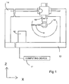
- Fig 1 illustrates a motorised scanning head mounted on a coordinate measuring machine (CMM).
- CMM coordinate measuring machine
- a workpiece 10 to be measured is mounted on a table 12 of the CMM 14 and a motorised scanning head 16 is mounted on a spindle 18 of the CMM 14.
- the spindle is driveable in the directions X,Y,Z relative to the table by motors in known manner.
- the motorised scanning head 16 comprises a fixed part formed by a base or housing 20 supporting a movable part in the form of a shaft 22 rotatable by a motor M1 relative to the housing 20 about an axis A1.
- the shaft 22 is secured to a further housing 24 which in turn supports a shaft 26 rotatable by a motor M2 relative to the housing 24 about an axis A2 perpendicular to the axis A1.
- a probe 28 with a stylus 29 having a workpiece-contacting tip 30 is mounted onto the motorised scanning head.
- the arrangement is such that the motors M1,M2 of the head can position the workpiece-contacting tip angularly about the axes A1 or A2 and the motors of the CMM can position the motorised scanning head linearly anywhere within the three-dimensional coordinate framework of the CMM to bring the stylus tip into a predetermined relationship with the surface being scanned.
- Linear position transducers are provided on the CMM for measuring linear displacement of the scanning head and angular position transducers T1 and T2 are provided in the scanning head for measuring angular displacement of the stylus about the respective axes A1 and A2.
- the A1 axis of the scanning head 16 is nominally parallel to the CMM Z axis (which is along the spindle 18).
- the scanning head may rotate the probe continuously about this axis.
- the A2 axis of the scanning head is orthogonal to its A1 axis.
- the system is provided with a computing device 17 such as a dedicated controller of the CMM or a separate computer.
- a computing device 17 such as a dedicated controller of the CMM or a separate computer. This contains a program to control motion of the CMM and/or probe head. This or a different controller may be used for the calculations required in the methods described below.
- This apparatus is suitable for scanning surface profiles, in particular those having a centre line, such as bores. This is usually done by moving the spindle of the CMM and thus the scanning head along the nominal centreline of the surface profile whilst the scanning head moves the stylus tip around the surface of the bore.
- This method takes advantage of the fact that rotary movement of the scanning head about the A1 and A2 axes is more responsive than linear motion of the CMM spindle about the X,Y and Z linear axes.
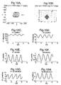
- Figs 4A and 4B illustrate the scan profile on the XY plane and the YZ plane respectively.
- Figs 4C and 4D illustrate the position of the stylus tip about the A1 and A2 axes respectively over time.
- Fig 4C shows the angle of the stylus tip about axis A1 varying linearly over time whereas Fig 4D shows the angle of the stylus tip about the A2 axis remaining constant.
- Figs 4E and 4F show the speed of the stylus tip about the A1 axis and A2 axis respectively.
- Fig 4E shows the stylus tip moving about the A1 axis at a constant velocity whereas Fig 4F shows that velocity about the A2 axis remains at zero.
- Figs 4G and 4H illustrate the acceleration of the stylus tip about the A1 and A2 axes respectively. In both cases there is zero acceleration.
- Fig 5 relates to the method of scanning a horizontal bore.
- the scanning head 16 is moved by the CMM spindle, along the nominal centre line 32 of the bore 34.
- the position of the stylus tip about both the A1 and A2 axes is modulated to keep the stylus tip on the surface of the bore and thereby maintain a steady probe deflection.
- Figs 6A and 6B show the scan profile on the XY plane and the YZ plane respectively.
- Figs 6C and 6D illustrate the stylus tip position about the A1 axis and A2 axis respectively. In both cases the position of the scanning head can be seen to be modulated.
- Figs 6E and 6F illustrate the velocity of the stylus tip about the A1 and A2 axes respectively. In both cases the velocity is modulated.
- Figs 6G and 6H illustrate the acceleration of the stylus tip about the A1 and A2 axes respectively. The acceleration of the stylus tip is modulated about both axes.
- Figs 8A and 8B illustrate the scan profile in the XY plane and the YZ plane respectively.
- Figs 8C and 8D illustrate the position of the stylus tip about the A1 and A2 axes respectively.
- Fig 8C shows the stylus tip being rotated about the A1 axis with some modulation occurring whilst Fig 8D shows the stylus tip being modulated about the A2 axis.
- Figs 8E and 8F illustrate the velocity of the stylus tip about the A1 and A2 axes respectively.
- Figs 8G and 8H show the acceleration of the stylus tip about the A1 and A2 axes respectively.
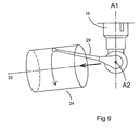
- Fig 9 illustrates a scan of a near horizontal bore. As before the scanning head 16 is moved by the CMM spindle along the nominal centreline 32 of the bore 34.
- Figs 10A and 10B illustrate the scan profile in the XY and YZ planes respectively.
- the stylus tip is modulated about both the A1 and A2 axes to keep the probe on the surface of the bore and maintain the probe deflection.
- Figs 10E and 10F illustrate the velocity of the stylus tip modulating about the A1 and A2 axes respectively.
- Figs 10G and 10H illustrate the acceleration of the stylus tip modulating about the A1 and A2 axes respectively.
- a bore may be orientated in a whole range of angles from near vertical to near horizontal. However at a particular bore angle the motion of the stylus tip about the A1 axis switches from continuous rotation to being modulated. This bore angle is referred to as the critical angle orientation.
- the stylus tip passes through an angle of 0° about the A2 axis relative to the A1 axis. As the stylus tip passes through this angle, the stylus becomes parallel to the A1 axis. This results in discontinuities in the scanning head's angular motion resulting in an infinite rotational velocity of the stylus tip about the A1 axis and step changes in its rotational velocity about the A2 axis thus causing infinite angular accelerations about the A1 and A2 axes. Similarly, for bores angled close to the critical angle orientation rapid changes in the scanning head's angular motion result in near infinite angular accelerations. Such motion cannot be achieved and it is thus physically impossible to scan bores orientated at or near the critical angle orientation using the method described above.
- the system may have a cranked stylus or a probe/stylus offset along the A2 axis.
- the critical angle problem relates to a line extending from the A2 axis to the stylus tip, which is normal to the A2 axis, becoming parallel or close to parallel to the A1 axis.
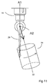
- Fig 11 illustrates a bore being scanned which is orientated at the critical angle orientation.
- the scanning head 16 is positioned such that the stylus is parallel to the A1 rotational axis of the scanning head. As the stylus passes through this position, step changes in the stylus position about the A1 axis and the velocity about the A2 axis result.
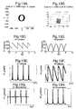
- Figs 12A to 12G illustrate a scan of a bore angled at fractionally less than the critical angle orientation.
- Figs 12A and 12B show the scan profile in the XY and YZ planes respectively.
- the stylus tip position about the A1 and A2 axes are shown in Figs 12C and 12D respectively. Step changes in the position of the stylus tip about the A1 axis can be seen in Fig 12C .
- Figs 12E and 12F illustrate the velocity of the stylus tip about the A1 and A2 axes respectively.
- Fig 12F illustrates the step changes in stylus tip velocity about the A2 axis and
- Fig 12E illustrates the stylus tip velocity required about the A1 axis tending towards infinity.
- Figs 12G and 12H illustrate the acceleration of the stylus tip about the A1 and A2 axes respectively. In both Figures, stylus tip accelerations that tend towards infinity are shown.
- Figs 13A-13G illustrate a scan of a bore angled at fractionally more than the critical angle orientation.
- Figs 13A and 13B show the scan profile in the XY and YZ planes respectively.
- the stylus tip positions about the A1 and A2 axes are shown in Figs 13C and 13D respectively.
- step changes in the position of the stylus tip about the A1 axis can be seen in Fig 13C .
- Figs 13E and 13F illustrate the velocity of the stylus tip about the A1 and A2 axes respectively.
- Fig 13F illustrates step changes in the stylus tip velocity about the A2 axis and
- Fig 13E illustrates the stylus tip velocity required about the A1 axis tending towards infinity.
- Figs 13G and 13H illustrate the acceleration of the stylus tip about the A1 and A2 axes respectively. In both Figures, stylus tip accelerations that tend towards infinity are shown.
- the critical angle problem occurs because the motorised scanning head has upper limits of the rotational velocity about the A1 axis and accelerations about the A1 and A2 axes.
- a rotational velocity and/or accelerations about the A1 and/or A2 axes are/is required which exceeds the upper limit of the motorised scanning head.
- a technique for predicting the critical angle problem using the velocity and acceleration scan parameters is outlined below, using a bore as an example.
- V A1 ⁇ sin ⁇ cos ⁇ sin ⁇ cos ⁇ t - sin ⁇ cos ⁇ cos ⁇ sin ⁇ - sin ⁇ cos ⁇ cos ⁇ t 2 + sin 2 ⁇ ⁇ ⁇ sin 2 ⁇ t
- V A2 ⁇ sin ⁇ sin ⁇ sin ⁇ t 1 - cos ⁇ cos ⁇ + sin ⁇ sin ⁇ cos ⁇ t 2 0.5
- a A ⁇ 2 a ⁇ g ⁇ cos 2 ⁇ t + q cos ⁇ t + g 1 - r + f cos ⁇ t 2 1.5
- J A ⁇ 2 - a ⁇ sin ⁇ t 2 g cos ⁇ t + q ⁇ 1 - r + f cos ⁇ t 2 + 3 ⁇ f ⁇ g ⁇ cos 2 ⁇ t + q cos ⁇ t + g ⁇ r + f cos ⁇ t 1 - r + f cos ⁇ t 2 2.5
- equations describe the entire scan rather than only the maximum magnitude. However, the equations can be used to determine the maximum magnitude of each of the predicted velocity about A1, acceleration about A1, velocity about A2 and acceleration about A2 for a required scanning scenario. These maximum values are compared with the maximum values permitted for a required scenario. If the magnitude of any of these predicted values exceeds the magnitude of the corresponding permitted value, then the scan is close enough to the critical angle to be a problem. If not, then no critical angle problem exists and the scan can proceed.
- a A1MAX cannot be found directly from an equation (no algebraic solution currently exists) and so it must be found iteratively from equation (2) above.
- V A2MAX will normally tend to infinity as the critical angle is approached during a scan.
- a A ⁇ 2 ⁇ Max ⁇ 2 sin ⁇ sin ⁇ sin ⁇ - ⁇ ⁇ ⁇ ⁇ ⁇
- Fig 14 is a graph of the maximum rotational velocity about the A1 axis against the bore elevation, for a given bore radius, stylus tip speed, probe length, and moving the scanning head along the bore axis.
- Dashed line 50 illustrates the upper limit of rotational velocity about the A1 axis for the motorised scanning head. It can be seen that for certain bore elevations, a maximum angular velocity about the A1 axis is required which exceeds the upper limit shown by line 50. Thus the scan cannot be done at this bore elevation using the current scan parameters.
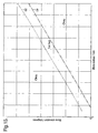
- Fig 15 shows a graph of bore elevation against bore radius for a scan of a bore along its centre line using a defined stylus tip speed, probe length and maximum rotational velocity about the A1 axis.
- the lines 52 and 54 show the limits respectively above and below which scans may be done using the scan profile. In the region between lines 52 and 54, the critical angle problem exists and the bore cannot be scanned using the scan profile.
- Equation (1) - (12) above may also be modified to take account of stylus tip diameter for a contact probe and offset for a non contact probe.
- Equations (2), (4), (7), (8), (9) and (10) are then used to determine whether for given values of probe length and stylus tip velocity, a maximum angular velocity about the A1 axis and/or the acceleration about the A1 and/or A2 axes will occur above the predetermined limits.
- some preliminary measurements may be taken to determine the bore elevation and radius. For example, measurements may be taken at the top and bottom of the bore or a spiral scan may be performed along the bore length to collect sufficient data to determine the bore elevation and radius. These may be used in equations (2), (4), (7), (8), (9) and (10) as described in the second method.
- the circumference of the bore may be partially scanned, avoiding the critical angle, at a single position along the bore's length, using the motorised scanning head and an estimation of the bore axis. If the scanning head is correctly positioned along the bore axis, an incomplete circular profile will result. Thus the bore elevation has been correctly estimated and the bore radius has been determined.
- a non-circular profile such as a tear drop shaped profile results, the motorised scanning head may not have been on the bore axis.
- the tear drop shape results as nominally the intersection of a sphere and a cylinder.
- sufficient data is available from the tear drop shaped profile to determine a theoretical centre line and radius of a perfect circle.
- the measurement data can be manipulated to produce a circular profile, all relating to the same height in Z of the bore.
- this has the disadvantage that it provides data that wasn't actually measured and assumes that the shape was caused by mis-alignment and not the part itself. It is possible that the tear drop shaped profile may be due to the shape of the part (however this is unlikely). A second scan on the theoretical centre line will confirm this.
- the critical angle problem may be overcome by changing one or more of the scan parameters.
- the width of the band where the problem exists, illustrated in Fig 15 between lines 52,54, may be reduced by reducing the stylus tip speed V.
- the position / width of the band may also be changed by re-orientating the bore elevation ⁇ or altering the probe length L.
- the probe offset may change instead of the probe length L.
- the probe offset should be kept within its calibrated range.
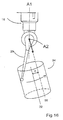
- Fig 16 illustrates the motorised scanning head moving along a path 56 which is offset from the bore axis 32 by a distance d. The direction of d relative to the centre line will be indicated by whether it is positive or negative.
- Fig 17 is a graph of maximum angular velocity about A1 axis against bore elevation, for a given bore radius, stylus tip speed and probe length. The three sets of data show that the change in offset d changes the bore elevation at which the critical angle problem exists.
- Figs 18A-18H illustrate a scan of a bore angled at the critical angle orientation. In this case the scanning head is moved along a trajectory parallel but offset to the nominal centre line of the bore.
- Figs 18A and 18B illustrate the scan profile in the XY and YZ planes respectively.
- Figs 18C and 18D illustrate the stylus tip position about the A1 and A2 axes respectively. There are no step changes in stylus tip position about either the A1 and A2 axes.
- Figs 18E and 18F illustrate the stylus tip velocity about the A1 and A2 axes respectively whilst Figs 18G and 18H illustrate the stylus tip acceleration about the A1 and A2 axes respectively.
- Figs 18E and 18F illustrate the stylus tip velocity about the A1 and A2 axes respectively
- Figs 18G and 18H illustrate the stylus tip acceleration about the A1 and A2 axes respectively.
- the normal trajectory of the scanning head is along the bore's nominal centre line which produces a symmetrical scan about the bore surface.
- the stylus will intersect the bore profile on a plane orthogonal to the nominal centre line of the bore.
- the scan will no longer be symmetrical around the bore surface. This results in areas on one side of the bore at one end and on the opposite side at the other end not being scanned.
- the scan length can be extended or a second scan can be performed with the axis offset on another side of the axis.
- the method of offsetting the trajectory of the scanning head is not limited to scanning a bore with a scanning head mounted on a vertical arm CMM.
- Other surface profiles may be measured using this method, such as cones, spheres and surfaces where the stylus tip approaches an angle of 0° about the A2 axis relative to the A1 axis during scanning.
- the surface profile is angled at a critical angle orientation by the following method. If the distance parallel to the A1 axis between the scanning head trajectory (i.e. the trajectory followed by the centre of the scanning head) and the surface is substantially the same as the probe length (distance from the probe's centre of rotation to its tip), then there is a critical angle problem. This may be tested by moving the scanning head to various points on its trajectory and using the head to rotate the probe tip in a direction towards the normal of the surface so that it passes through a line parallel to the A1 axis.
- the likelihood of a critical angle can be determined from the position at which the probe tip makes contact with the surface.
- the scanning head angle, velocity and acceleration profiles about the A1 and A2 axes do not repeat every revolution of the stylus tip around the cone's profile as the CMM moves the scanning head along the centre line of the profile.
- a critical or near critical angle may thus be encountered during one particular revolution of the probe tip but not during any other revolutions. Offsetting the trajectory of the scanning head from the cone's centre line may not remedy this situation, but only shift the critical or near critical angle to another revolution of the probe tip.
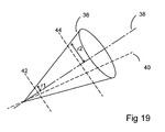
- Fig 19 illustrates a conical surface profile 36 with a nominal centre line 38.
- the modified trajectory 40 is shown passing through the apex of the cone.
- a similar approach may be taken with spheres, or other surfaces which present the same problem.
- the upper radius and lower radius are the radii of the profile plus (for convex profiles) or minus (for concave profiles) the probe tip radius.
- the solution comprises the reduction of the angular velocity of the scan (i.e. stylus tip in the scan plane), thereby reducing the required angular velocities and accelerations about A1 and A2 axes.
- the scan velocity may be reduced in different ways.
- the scan velocity may be reduced for the whole scan or for a section of the scan in which permitted values would be exceeded.
- the reduction in scan velocity may take the form of a modulation, so that the scan velocity is varying throughout the scan and approaches its minimum when it is closest to the critical angle.
- the reduction in scan velocity may be applied using some other curve of velocity against scan position for each scan revolution.
- This solution is thus suitable for scans in which the permitted maximums of angular velocity and accelerations are exceeded and the solution ensures that the angular velocities and accelerations about the A1 and A2 axes are always within permitted limits.
- a further solution comprises using the gaps between measurement points to skip over the critical angle.
- This technique can be used for scans which pass through the critical angle and also for scans which contain a section close to the critical angle, including those for which the technique outlined above would require a reduction in scan angular velocity which was impractically large.
- This solution applies to the discrete points that are generated to drive the probe tip around the scan profile.
- the gaps are arranged between these points such that a gap coincides with the critical angle.
- the scan then skips over the critical angle and hence does not require the impossible infinite velocities and accelerations about the A1 and A2 axes.
- the same principle can also be used to skip over a section of the scan for which the required angular velocities and accelerations about the A1 and A2 axes are prohibitive. The larger the section of the scan to be skipped, the greater the resulting distance between points (i.e. the lower the point density).
- This solution may be combined with the solution above, as a reduction in scan velocity during the problematic scan section will reduce the length of section which requires prohibitive angular velocities and accelerations about the A1 and A2 axes. This will increase the maximum point density, which can be used to skip the section.
- the probe deflection will change and the probe may even leave the surface of the profile. Thus re-loading of the probe deflection on the surface may be required after the skip.
- a combined methodology for dealing with the critical angle problem may be used. This detects which of several solutions (e.g. axis offset, slow down and combination of reducing scan velocity and skipping over the critical angle) is preferable, based on the specific numerical criteria for a given application. The scan parameters may then be modified accordingly and the scan performed.
- solutions e.g. axis offset, slow down and combination of reducing scan velocity and skipping over the critical angle
- the bore may be measured as previously described. However, if the orientation of the surface profile is close to the critical angle orientation corrective measures must be taken.
- the scanning head may be mounted on any type of CMM, for example, a horizontal arm CMM, or may be mounted in any orientation. For example it may be mounted horizontally on the vertical arm CMM.
- the scanning head may be mounted on other types of coordinate positioning machines, such as a machine tool.
- the method is also suitable for taking discrete measurements with a touch trigger probe.
- This method is also suitable for use irrespective of whether motion about A1 and A2 axes is guided by the surface of a workpiece.
- free space motion of the articulating probe head can also experience the critical angle problem as described above.
- the critical angle problem for motion which is not guided by a specifically located geometry can be solved by choosing an appropriate solution from those outlined above.
- the methods described above therefore allow the prediction of any motion about the A1 and A2 axes which will pass through the critical angle, or sufficiently close to it to cause angular velocities and/or accelerations to become prohibitive.
- the methods also enable this problem to be solved by changing one or more of the scan parameters.
- This invention is not limited to metrological scanning but is suitable for applications in fields other than metrology where the critical angle problem could occur.
Description
- The present invention relates to a method of scanning the surface of a workpiece using a motorised scanning head mounted on a coordinate positioning apparatus such as a coordinate measuring machine (CMM), machine tool, manual coordinate measuring arms and inspection robots.
- It is known from International Patent Application No.
WO90/07097 - Such a motorised scanning head provides a coordinate positioning machine with greater scanning flexibility because the motorised scanning head can position the stylus in many different orientations.
-
WO90/07097 - This is a simple procedure for most surface profiles. However we have discovered that for scans during which the angle of the stylus is such that it becomes substantially parallel to one of the rotational axes, hereinafter referred to as the "critical angle", discontinuities in the scanning head's angular motion result from this scanning method. These discontinuities are caused by a requirement for an infinite rotational velocity about the one axis and a step change in rotational velocity about the other axis resulting in infinite angular accelerations about both these axes. Similarly for scans of profiles where the angle of the stylus comes close to this critical angle, rapid changes in the scanning head's angular motion result in near infinite angular accelerations. As such motions cannot be achieved it is physically impossible to scan surface profiles which will result in the stylus being oriented at or near the critical angle using the method described above.
- The term 'critical angle problem' is used to refer to a problem due to one or more angular values (velocity and acceleration about A1 and A2) being greater than a permitted value. Hence the term refers to scans which require the probe to be at some point where there are discontinuities in the scanning head's angular motion and to scans which require the probe to move close enough to the critical angle for one of the angular values to exceed that which is permitted for the scan (usually due to a hardware limitation).
- As already stated when scanning a profile with a centre line, the scanning head is normally moved along the centre line. However, it has been found that for certain orientations of the profile, the critical angle may be encountered. Such orientations will hereinafter be referred to as the 'critical angle orientation'.
- Other documents describing scanning methods for coordinate measuring apparatus are described in
US5726971 ,US6154713 andDE10050795 . - The invention provides an apparatus according to
claim 12 and methods according toclaims - The methods are suitable for a multi-axis probe head, such as a 3-axis probe head in which the trajectory is chosen to prevent the surface detecting device from becoming parallel to any of the rotational axes of the probe head during the scan.
- Examples of preferred embodiments of the invention will now be described with reference to the accompanying drawings wherein:
-
Fig 1 is an elevation of a coordinate measuring machine including scanning apparatus according to the present invention; -
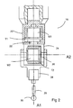
Fig 2 is a cross-section of a motorised scanning head; -
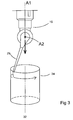
Fig 3 illustrates a vertical bore being scanned; -
Figs 4A and 4B illustrate the scan profile in the XY and YZ plane respectively for a vertical bore; -
Figs 4C and 4D illustrate the stylus tip position about the A1 and A2 axes respectively during the scan of a vertical bore; -
Figs 4E and 4F illustrate the stylus tip velocity about the A1 and A2 axes respectively during the scan of a vertical bore; -
Figs 4G and 4H illustrate the stylus tip acceleration about the A1 and A2 axes respectively during the scan of a vertical bore; -
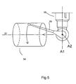
Fig 5 illustrates a horizontal bore being scanned; -
Figs 6A and 6B illustrate the scan profile in the XY and YZ planes respectively for a horizontal bore; -
Figs 6C and 6D illustrate the stylus tip position about the A1 and A2 axes respectively during the scan of a horizontal bore; -
Figs 6E and 6F illustrate the stylus tip velocity about the A1 and A2 axes respectively during the scan of a horizontal bore; -
Figs 6G and 6H illustrate the stylus tip acceleration about the A1 and A2 axes respectively during the scan of a vertical bore; -
Fig 7 illustrates a near vertical bore being scanned; -
Figs 8A and 8B illustrate the scan profile in the XY and YZ plane respectively for a near vertical bore; -
Figs 8C and 8D illustrate the stylus tip position about the A1 and A2 axes respectively during the scan of a near vertical bore; -
Figs 8E and 8F illustrate the stylus tip velocity about the A1 and A2 axes respectively during the scan of a near vertical bore; -
Figs 8G and 8H illustrate the stylus tip acceleration about the A1 and A2 axes respectively during the scan of a near vertical bore; -
Fig 9 illustrates a near horizontal bore being scanned; -
Figs 10A and 10B illustrate the scan profile in the XY and YZ planes respectively for a near horizontal bore; -
Figs 10C and 10D illustrate the stylus tip position about the A1 and A2 axes respectively during the scan of a near horizontal bore; -
Figs 10E and 10F illustrate the stylus tip velocity about the A1 and A2 axes respectively during the scan of a near horizontal bore; -
Figs 10G and 10H illustrate the stylus tip acceleration about the A1 and A2 axes respectively during the scan of a near horizontal bore; -
Fig 11 illustrates a bore angled at a critical angle orientation being scanned by moving the scanning head along the nominal centre line; -
Figs 12A and 12B illustrate the scan profile in the XY and YZ planes respectively for a bore angled at fractionally less than the critical angle orientation; -
Figs 12C and 12D illustrate the stylus tip position about the A1 and A2 axes respectively during the scan of a bore angled at fractionally less than the critical angle orientation; -
Figs 12E and 12F illustrate the stylus tip velocity about the A1 and A2 axes respectively during the scan of a bore angled at fractionally less than the critical angle orientation; -
Figs 12G and 12H illustrate the stylus tip acceleration about the A1 and A2 axes respectively during the scan of a bore angled at fractionally less than the critical angle orientation; -
Figs 13A and 13B illustrate the scan profile in the XY and YZ planes respectively for a bore angled at fractionally more than the critical angle orientation; -
Figs 13C and 13D illustrate the stylus tip position about the A1 and A2 axes respectively during the scan of a bore angled at fractionally more than the critical angle orientation; -
Figs 13E and 13F illustrate the stylus tip velocity about the A1 and A2 axes respectively during the scan of a bore angled at fractionally more than the critical angle orientation; -
Figs 13G and 13H illustrate the stylus tip acceleration about the A1 and A2 axes respectively during the scan of a bore angled at fractionally more than the critical angle orientation; -
Fig 14 is a graph of maximum rotational velocity about the A1 axis against bore elevation; -
Fig 15 is a graph of bore elevation against bore radius; -
Fig 16 illustrates a bore angled at a critical angle orientation being scanned by moving the scanning head along a path offset but parallel to the nominal centre line; -
Fig 17 is a graph of maximum angular velocity about A1 axis against bore elevation; -
Figs 18A and 18B illustrate the scan profile in the XY and YZ planes respectively for a critical angle orientation bore using an offset trajectory; -
Figs 18C and 18D illustrate the stylus tip position about the A1 and A2 axes respectively during the scan of a critical angle orientation bore using an offset trajectory; -
Figs 18E and 18F illustrate the stylus tip velocity about the A1 and A2 axes respectively during the scan of a critical angle orientation bore using an offset trajectory; -
Figs 18G and 18H illustrate the stylus tip acceleration about the A1 and A2 axes respectively during the scan of a critical angle orientation bore using an offset trajectory; and -
Fig 19 illustrates a cone which is scanned using a trajectory offset from the nominal centre line. -
Fig 1 illustrates a motorised scanning head mounted on a coordinate measuring machine (CMM). Aworkpiece 10 to be measured is mounted on a table 12 of theCMM 14 and amotorised scanning head 16 is mounted on aspindle 18 of theCMM 14. The spindle is driveable in the directions X,Y,Z relative to the table by motors in known manner. - As illustrated in
Fig 2 , themotorised scanning head 16 comprises a fixed part formed by a base orhousing 20 supporting a movable part in the form of ashaft 22 rotatable by a motor M1 relative to thehousing 20 about an axis A1. Theshaft 22 is secured to afurther housing 24 which in turn supports ashaft 26 rotatable by a motor M2 relative to thehousing 24 about an axis A2 perpendicular to the axis A1. - A
probe 28 with astylus 29 having a workpiece-contactingtip 30 is mounted onto the motorised scanning head. The arrangement is such that the motors M1,M2 of the head can position the workpiece-contacting tip angularly about the axes A1 or A2 and the motors of the CMM can position the motorised scanning head linearly anywhere within the three-dimensional coordinate framework of the CMM to bring the stylus tip into a predetermined relationship with the surface being scanned. - Linear position transducers are provided on the CMM for measuring linear displacement of the scanning head and angular position transducers T1 and T2 are provided in the scanning head for measuring angular displacement of the stylus about the respective axes A1 and A2.
- On a vertical arm CMM as shown in
Fig 1 , the A1 axis of thescanning head 16 is nominally parallel to the CMM Z axis (which is along the spindle 18). The scanning head may rotate the probe continuously about this axis. The A2 axis of the scanning head is orthogonal to its A1 axis. - The system is provided with a
computing device 17 such as a dedicated controller of the CMM or a separate computer. This contains a program to control motion of the CMM and/or probe head. This or a different controller may be used for the calculations required in the methods described below. - This apparatus is suitable for scanning surface profiles, in particular those having a centre line, such as bores. This is usually done by moving the spindle of the CMM and thus the scanning head along the nominal centreline of the surface profile whilst the scanning head moves the stylus tip around the surface of the bore. This method takes advantage of the fact that rotary movement of the scanning head about the A1 and A2 axes is more responsive than linear motion of the CMM spindle about the X,Y and Z linear axes.
- Scanning of a vertical bore will now be described with reference to
Fig 3 . Here, thescanning head 16 is moved by the CMM spindle along thenominal centre line 32 of thebore 34. Thescanning head 16 rotates thestylus 29 continuously about the A1 axis whilst the stylus is kept at a nominally constant angle about the A2 axis to keep the probe on the surface of the bore. However in reality, the angle of the stylus about the A2 axis may vary slightly to maintain a steady probe deflection (or probe force).Figs 4A and 4B illustrate the scan profile on the XY plane and the YZ plane respectively. -
Figs 4C and 4D illustrate the position of the stylus tip about the A1 and A2 axes respectively over time.Fig 4C shows the angle of the stylus tip about axis A1 varying linearly over time whereasFig 4D shows the angle of the stylus tip about the A2 axis remaining constant.Figs 4E and 4F show the speed of the stylus tip about the A1 axis and A2 axis respectively.Fig 4E shows the stylus tip moving about the A1 axis at a constant velocity whereasFig 4F shows that velocity about the A2 axis remains at zero.Figs 4G and 4H illustrate the acceleration of the stylus tip about the A1 and A2 axes respectively. In both cases there is zero acceleration. -
Fig 5 relates to the method of scanning a horizontal bore. As described above, thescanning head 16 is moved by the CMM spindle, along thenominal centre line 32 of thebore 34. In this case the position of the stylus tip about both the A1 and A2 axes is modulated to keep the stylus tip on the surface of the bore and thereby maintain a steady probe deflection.Figs 6A and 6B show the scan profile on the XY plane and the YZ plane respectively. -
Figs 6C and 6D illustrate the stylus tip position about the A1 axis and A2 axis respectively. In both cases the position of the scanning head can be seen to be modulated.Figs 6E and 6F illustrate the velocity of the stylus tip about the A1 and A2 axes respectively. In both cases the velocity is modulated.Figs 6G and 6H illustrate the acceleration of the stylus tip about the A1 and A2 axes respectively. The acceleration of the stylus tip is modulated about both axes. - Scanning of a near vertical bore will now be described with reference to
Fig 7 . As before thescanning head 16 is moved by the CMM spindle along the bore'snominal centre line 32. Thestylus tip 30 is rotated continuously about the A1 axes and is modulated about both the A1 and A2 axes to keep the stylus tip on the surface of the bore, thus maintaining a steady probe deflection.Figs 8A and 8B illustrate the scan profile in the XY plane and the YZ plane respectively. -
Figs 8C and 8D illustrate the position of the stylus tip about the A1 and A2 axes respectively.Fig 8C shows the stylus tip being rotated about the A1 axis with some modulation occurring whilstFig 8D shows the stylus tip being modulated about the A2 axis.Figs 8E and 8F illustrate the velocity of the stylus tip about the A1 and A2 axes respectively.Figs 8G and 8H show the acceleration of the stylus tip about the A1 and A2 axes respectively. -
Fig 9 illustrates a scan of a near horizontal bore. As before thescanning head 16 is moved by the CMM spindle along thenominal centreline 32 of thebore 34.Figs 10A and 10B illustrate the scan profile in the XY and YZ planes respectively. - As shown in
Figs 10C and 10D , the stylus tip is modulated about both the A1 and A2 axes to keep the probe on the surface of the bore and maintain the probe deflection.Figs 10E and 10F illustrate the velocity of the stylus tip modulating about the A1 and A2 axes respectively.Figs 10G and 10H illustrate the acceleration of the stylus tip modulating about the A1 and A2 axes respectively. - As discussed above, when scanning near vertical bores the stylus tip is required to rotate about the A1 axis continuously whilst being modulated about the A2 axis. When scanning near horizontal bores the stylus tip is required to be modulated about both the A1 and A2 axis. A bore may be orientated in a whole range of angles from near vertical to near horizontal. However at a particular bore angle the motion of the stylus tip about the A1 axis switches from continuous rotation to being modulated. This bore angle is referred to as the critical angle orientation.
- During the scan of a bore angled at this critical angle orientation, the stylus tip passes through an angle of 0° about the A2 axis relative to the A1 axis. As the stylus tip passes through this angle, the stylus becomes parallel to the A1 axis. This results in discontinuities in the scanning head's angular motion resulting in an infinite rotational velocity of the stylus tip about the A1 axis and step changes in its rotational velocity about the A2 axis thus causing infinite angular accelerations about the A1 and A2 axes. Similarly, for bores angled close to the critical angle orientation rapid changes in the scanning head's angular motion result in near infinite angular accelerations. Such motion cannot be achieved and it is thus physically impossible to scan bores orientated at or near the critical angle orientation using the method described above.
- The system may have a cranked stylus or a probe/stylus offset along the A2 axis. In this case, the critical angle problem relates to a line extending from the A2 axis to the stylus tip, which is normal to the A2 axis, becoming parallel or close to parallel to the A1 axis.
-
Fig 11 illustrates a bore being scanned which is orientated at the critical angle orientation. At the point in the scan illustrated inFig 11 , thescanning head 16 is positioned such that the stylus is parallel to the A1 rotational axis of the scanning head. As the stylus passes through this position, step changes in the stylus position about the A1 axis and the velocity about the A2 axis result. -
Figs 12A to 12G illustrate a scan of a bore angled at fractionally less than the critical angle orientation.Figs 12A and 12B show the scan profile in the XY and YZ planes respectively. The stylus tip position about the A1 and A2 axes are shown inFigs 12C and 12D respectively. Step changes in the position of the stylus tip about the A1 axis can be seen inFig 12C . -
Figs 12E and 12F illustrate the velocity of the stylus tip about the A1 and A2 axes respectively.Fig 12F illustrates the step changes in stylus tip velocity about the A2 axis andFig 12E illustrates the stylus tip velocity required about the A1 axis tending towards infinity. -
Figs 12G and 12H illustrate the acceleration of the stylus tip about the A1 and A2 axes respectively. In both Figures, stylus tip accelerations that tend towards infinity are shown. -
Figs 13A-13G illustrate a scan of a bore angled at fractionally more than the critical angle orientation.Figs 13A and 13B show the scan profile in the XY and YZ planes respectively. The stylus tip positions about the A1 and A2 axes are shown inFigs 13C and 13D respectively. As before, step changes in the position of the stylus tip about the A1 axis can be seen inFig 13C . -
Figs 13E and 13F illustrate the velocity of the stylus tip about the A1 and A2 axes respectively.Fig 13F illustrates step changes in the stylus tip velocity about the A2 axis andFig 13E illustrates the stylus tip velocity required about the A1 axis tending towards infinity. -
Figs 13G and 13H illustrate the acceleration of the stylus tip about the A1 and A2 axes respectively. In both Figures, stylus tip accelerations that tend towards infinity are shown. - The critical angle problem occurs because the motorised scanning head has upper limits of the rotational velocity about the A1 axis and accelerations about the A1 and A2 axes. When a bore is orientated at this critical angle orientation, a rotational velocity and/or accelerations about the A1 and/or A2 axes are/is required which exceeds the upper limit of the motorised scanning head.
- In order to identify whether critical angle orientation counter measures need to be taken it is necessary to determine whether a limit of the angular velocity about the A1 axis and/or the accelerations about the A1 and/or A2 axes will be exceeded. It may also be determined whether a critical angle problem occurs by determining whether a position demand occurs which requires the stylus to become substantially parallel to the A1 axis.
- A technique for predicting the critical angle problem using the velocity and acceleration scan parameters is outlined below, using a bore as an example.
- The magnitudes of angular velocity VA1, angular acceleration AA1 and Jerk JA1 (rate of change of acceleration) about the A1 axis can be determined for any point on the scan from the following equations.


where - ω: Angular velocity of scan (i.e.: of tip in scan plane) [radians/sec]
- φ: Angle subtended about the (A1, A2) axis intersection by the bore radius. [Units irrelevant as always used in trigonometric functions.]
- θ: Bore elevation. [Units irrelevant as always used in trigonometric functions.]
- t: Time since scan began [seconds]. Zero is at closest point to A1 axis.
- And where the constants in equations (1), (2) and (3) are defined as follows:


- The magnitudes of angular velocity VA2, angular acceleration AA2 and Jerk JA2 about the A2 axis can be determined for any point on the scan from the following equations.


- Where the constants in equations (4), (5) and (6) are as per the constants in equations (1), (2) and (3) and also defined as follows:


- These equations describe the entire scan rather than only the maximum magnitude. However, the equations can be used to determine the maximum magnitude of each of the predicted velocity about A1, acceleration about A1, velocity about A2 and acceleration about A2 for a required scanning scenario. These maximum values are compared with the maximum values permitted for a required scenario. If the magnitude of any of these predicted values exceeds the magnitude of the corresponding permitted value, then the scan is close enough to the critical angle to be a problem. If not, then no critical angle problem exists and the scan can proceed.
- As mentioned above, the equations above can be used to derive the maximum magnitudes of angular velocity and acceleration about A1 and A2. These are found as follows:

- This result is positive for θ > φ and negative for θ < φ. At θ = φ the critical angle case occurs and V = ∞.
- AA1MAX cannot be found directly from an equation (no algebraic solution currently exists) and so it must be found iteratively from equation (2) above.
- VA2MAX occurs when cos(ωt) is given by the following expression:

- The positive case should be used when θ ≤ φ, the negative case when θ ≥ φ. (Outside these ranges |cos(ωt)| > 1.) The resulting value of cos (ωt) corresponds to two values of t during one complete scan revolution (i.e.: when ωt ∈ [0,2π[). When substituted into the equation (4) for V A2 these give the maximum and minimum values of VA2 angular velocity.
- It is not anticipated that VA2MAX will normally tend to infinity as the critical angle is approached during a scan.

- This result is always positive. At θ = φ the critical angle orientation case occurs and AA2MAX = ∞.
- These equations describe a bore having specific scan parameters. These are as follows: the bore axis should lie in the plane in which A1 is zero and time is measured such that it is zero at the tip's closest point to the A1 axis. Any scan which does not involve these specific parameters can be modified (e.g. using rotation of axes, adding a constant to measure time etc) such that the constant features become true for that scan. Bore elevations of 0 to 90° degrees are supported by these equations.
- The implications of the bore's parameters on the angular velocity around the A1 axis will now be examined, to illustrate the effect of the critical angle. The angular velocity ω about the axis A1 required for scanning a bore, whilst moving the scanning head along the centre line, is calculated using the equation below:

- where, ω = maximum rotational velocity about the A1
- axis [revs per second]
- V = stylus tip speed [mm per second]
- L = probe length [mm]
- r = bore radius [mm]
- θ = bore elevation [units irrelevant as always implied by trigonometric functions]
-
Fig 14 is a graph of the maximum rotational velocity about the A1 axis against the bore elevation, for a given bore radius, stylus tip speed, probe length, and moving the scanning head along the bore axis. Dashedline 50 illustrates the upper limit of rotational velocity about the A1 axis for the motorised scanning head. It can be seen that for certain bore elevations, a maximum angular velocity about the A1 axis is required which exceeds the upper limit shown byline 50. Thus the scan cannot be done at this bore elevation using the current scan parameters. - For a given bore radius, probe length and stylus tip speed, it can be determined at what bore elevations a scan may be carried out using the current scan profile. These allowable bore elevations may be calculated from the equations below, which are derived from equation (10) above:


where ωmax - maximum rotational velocity about the A1 axis. -
Fig 15 shows a graph of bore elevation against bore radius for a scan of a bore along its centre line using a defined stylus tip speed, probe length and maximum rotational velocity about the A1 axis. Thelines lines - The equations (1) - (12) above may also be modified to take account of stylus tip diameter for a contact probe and offset for a non contact probe.
- There are several different methods by which it can be determined whether a critical angle problem will exist for a scan of any particular part. Firstly, it can be determined whether the demanded angular velocity about the A1 axis and/or the acceleration about the A1 and/or A2 axes exceeds the predetermined limits anywhere in the scan. (Or alternatively if the demanded position is unacceptable). If this is the case, then an error is indicated and the scan parameters are adjusted to overcome the problem, as will be discussed further below. However, it may not be possible to pre-calculate the acceleration, velocity or position values. In this case, if during a scan sudden steps in position demand are encountered, then the scan will abort and the scan parameters will need to be adjusted.
- In a second method, the CAD drawings of the part to be measured are used to provide the bore elevation and diameter. Equations (2), (4), (7), (8), (9) and (10)are then used to determine whether for given values of probe length and stylus tip velocity, a maximum angular velocity about the A1 axis and/or the acceleration about the A1 and/or A2 axes will occur above the predetermined limits.
- In a third method, some preliminary measurements may be taken to determine the bore elevation and radius. For example, measurements may be taken at the top and bottom of the bore or a spiral scan may be performed along the bore length to collect sufficient data to determine the bore elevation and radius. These may be used in equations (2), (4), (7), (8), (9) and (10) as described in the second method. Alternatively, the circumference of the bore may be partially scanned, avoiding the critical angle, at a single position along the bore's length, using the motorised scanning head and an estimation of the bore axis. If the scanning head is correctly positioned along the bore axis, an incomplete circular profile will result. Thus the bore elevation has been correctly estimated and the bore radius has been determined.
- If a non-circular profile, such as a tear drop shaped profile results, the motorised scanning head may not have been on the bore axis. The tear drop shape results as nominally the intersection of a sphere and a cylinder. However sufficient data is available from the tear drop shaped profile to determine a theoretical centre line and radius of a perfect circle. The measurement data can be manipulated to produce a circular profile, all relating to the same height in Z of the bore. However this has the disadvantage that it provides data that wasn't actually measured and assumes that the shape was caused by mis-alignment and not the part itself. It is possible that the tear drop shaped profile may be due to the shape of the part (however this is unlikely). A second scan on the theoretical centre line will confirm this.
- Thus using equations (2), (4), (7), (8), (9) and (10), as described in the second method, it may be determined whether the critical angle problem exists.
- The critical angle problem may be overcome by changing one or more of the scan parameters. The width of the band where the problem exists, illustrated in
Fig 15 betweenlines - For a non-contact probe, the probe offset may change instead of the probe length L. However the probe offset should be kept within its calibrated range.
- The critical angle problem may also be avoided by offsetting the path of the scanning head from the bore axis.
Fig 16 illustrates the motorised scanning head moving along apath 56 which is offset from thebore axis 32 by a distance d. The direction of d relative to the centre line will be indicated by whether it is positive or negative. - The maximum angular velocity about axis A1,ω, may be determined for the new scan path by the following equation:

where d is the scanning head axis distance. d is signed such that a negative value implies offset toward the point on the bore surface at which A2 is closest to the critical angle. -
Fig 17 is a graph of maximum angular velocity about A1 axis against bore elevation, for a given bore radius, stylus tip speed and probe length. The three sets of data show that the change in offset d changes the bore elevation at which the critical angle problem exists. - The required offset for a particular scan and a maximum permitted angular velocity about A1, ωmax can be determined by rearranging equation (13):

-
Figs 18A-18H illustrate a scan of a bore angled at the critical angle orientation. In this case the scanning head is moved along a trajectory parallel but offset to the nominal centre line of the bore.Figs 18A and 18B illustrate the scan profile in the XY and YZ planes respectively. -
Figs 18C and 18D illustrate the stylus tip position about the A1 and A2 axes respectively. There are no step changes in stylus tip position about either the A1 and A2 axes. -
Figs 18E and 18F illustrate the stylus tip velocity about the A1 and A2 axes respectively whilstFigs 18G and 18H illustrate the stylus tip acceleration about the A1 and A2 axes respectively. There are no step changes in stylus tip velocity. In addition, there are no infinite velocities or accelerations required. This method of offsetting the trajectory of the scanning head from the nominal centre line of the bore allows a bore angled at a critical angle orientation to be scanned without the need of altering the probe length. - As previously described, the normal trajectory of the scanning head is along the bore's nominal centre line which produces a symmetrical scan about the bore surface. Thus for a certain scanning head position, the stylus will intersect the bore profile on a plane orthogonal to the nominal centre line of the bore. However when the trajectory of the scanning head is offset from the nominal centre line, the scan will no longer be symmetrical around the bore surface. This results in areas on one side of the bore at one end and on the opposite side at the other end not being scanned.
- If there is a requirement for measurements of these areas of the bore surface profile, additional scans may be carried out on these surfaces. Alternatively, the scan length can be extended or a second scan can be performed with the axis offset on another side of the axis.
- The method of offsetting the trajectory of the scanning head is not limited to scanning a bore with a scanning head mounted on a vertical arm CMM. Other surface profiles may be measured using this method, such as cones, spheres and surfaces where the stylus tip approaches an angle of 0° about the A2 axis relative to the A1 axis during scanning.
- For other surface profiles, it can be determined whether the surface profile is angled at a critical angle orientation by the following method. If the distance parallel to the A1 axis between the scanning head trajectory (i.e. the trajectory followed by the centre of the scanning head) and the surface is substantially the same as the probe length (distance from the probe's centre of rotation to its tip), then there is a critical angle problem. This may be tested by moving the scanning head to various points on its trajectory and using the head to rotate the probe tip in a direction towards the normal of the surface so that it passes through a line parallel to the A1 axis.
- The likelihood of a critical angle can be determined from the position at which the probe tip makes contact with the surface.
- In the case of cones, the scanning head angle, velocity and acceleration profiles about the A1 and A2 axes do not repeat every revolution of the stylus tip around the cone's profile as the CMM moves the scanning head along the centre line of the profile. A critical or near critical angle may thus be encountered during one particular revolution of the probe tip but not during any other revolutions. Offsetting the trajectory of the scanning head from the cone's centre line may not remedy this situation, but only shift the critical or near critical angle to another revolution of the probe tip.
- This problem is overcome by changing the head trajectory so that the critical or near critical angle is not encountered anywhere during the scan. This modified trajectory does not need to be parallel to the centre line of the profile as previously described.
Fig 19 illustrates aconical surface profile 36 with anominal centre line 38. The modifiedtrajectory 40 is shown passing through the apex of the cone. A similar approach may be taken with spheres, or other surfaces which present the same problem. - As shown in
Fig 19 , when scanning along and around the cone between two planes, afirst plane 42 towards the apex of the cone having a "lower radius" r1 and asecond plane 44 further away from the apex of the cone having an "upper radius" r2, the critical angle problem will occur if: - arcsine (lower radius/probe length) <= angle of nominal centre line of surface profile
- and
- arcsine (upper radius/probe length) >= angle of nominal centre line of surface profile.
- In the above equations, the upper radius and lower radius are the radii of the profile plus (for convex profiles) or minus (for concave profiles) the probe tip radius.
- These equations are also true for hemi-sphere. It is not required that the surface profile has a nominal centre line. Any surface profile may be scanned in which a trajectory is chosen to avoid the stylus becoming substantially parallel to the A1 axis.
- An alternative solution to the critical angle problem involves changing the angular velocity of the scan and is described in more detail below. This method is suitable for scans which pass close to (but not through) the critical angle such that the required angular velocities and/or accelerations about the A1 and A2 axes exceed their permitted values.
- The solution comprises the reduction of the angular velocity of the scan (i.e. stylus tip in the scan plane), thereby reducing the required angular velocities and accelerations about A1 and A2 axes.
- The scan velocity may be reduced in different ways.
- The scan velocity may be reduced for the whole scan or for a section of the scan in which permitted values would be exceeded. Alternatively, the reduction in scan velocity may take the form of a modulation, so that the scan velocity is varying throughout the scan and approaches its minimum when it is closest to the critical angle. The reduction in scan velocity may be applied using some other curve of velocity against scan position for each scan revolution.
- This solution has the disadvantage that it cannot be used if the scan passes through the critical angle because at this point some of the required angular velocities and accelerations about A1 and A2 are infinite and this cannot be reduced by any factor due to the reduction of scan velocity.
- This solution is thus suitable for scans in which the permitted maximums of angular velocity and accelerations are exceeded and the solution ensures that the angular velocities and accelerations about the A1 and A2 axes are always within permitted limits.
- A further solution comprises using the gaps between measurement points to skip over the critical angle. This technique can be used for scans which pass through the critical angle and also for scans which contain a section close to the critical angle, including those for which the technique outlined above would require a reduction in scan angular velocity which was impractically large.
- This solution applies to the discrete points that are generated to drive the probe tip around the scan profile. The gaps are arranged between these points such that a gap coincides with the critical angle. The scan then skips over the critical angle and hence does not require the impossible infinite velocities and accelerations about the A1 and A2 axes. The same principle can also be used to skip over a section of the scan for which the required angular velocities and accelerations about the A1 and A2 axes are prohibitive. The larger the section of the scan to be skipped, the greater the resulting distance between points (i.e. the lower the point density).
- This solution may be combined with the solution above, as a reduction in scan velocity during the problematic scan section will reduce the length of section which requires prohibitive angular velocities and accelerations about the A1 and A2 axes. This will increase the maximum point density, which can be used to skip the section.
- During the skip over the critical angle, the probe deflection will change and the probe may even leave the surface of the profile. Thus re-loading of the probe deflection on the surface may be required after the skip.
- A combined methodology for dealing with the critical angle problem may be used. This detects which of several solutions (e.g. axis offset, slow down and combination of reducing scan velocity and skipping over the critical angle) is preferable, based on the specific numerical criteria for a given application. The scan parameters may then be modified accordingly and the scan performed.
- If the orientation of the surface profile is not close to the critical angle orientation the bore may be measured as previously described. However, if the orientation of the surface profile is close to the critical angle orientation corrective measures must be taken.
- In this case, the most appropriate solution is chosen, taking into consideration the other features on the part to be measured.
- In deciding whether to reorient the part, access to the feature must be considered and also the other features to be scanned must be taken into account, i.e. whether there is sufficient access at the new orientation and whether the critical angle problem will occur for these other features at the new orientation.
- Likewise, in deciding whether to change the length of stylus it must be taken into consideration the constraints of the feature itself. For example for a long bore, a long stylus may be required. Furthermore the stylus requirements for other features on the part may be taken into account to minimise changes of stylus which will slow down the total scan time.
- When applying the solutions to the critical angle problem described above it is important to ensure that an axis shift which corrects one angular value does not result in a newly introduced excessive angular value for velocity or acceleration. In this case, a new offset must be calculated. This method allows the scan to proceed about a scan axis which is offset from the bore axis and is parallel to it, without any of the angular values exceeding the required values.
- The scanning head may be mounted on any type of CMM, for example, a horizontal arm CMM, or may be mounted in any orientation. For example it may be mounted horizontally on the vertical arm CMM. The scanning head may be mounted on other types of coordinate positioning machines, such as a machine tool.
- Although the embodiments above describe the use of a contact probe mounted on a motorised scanning head, this method is also suitable for use with a non-contact probe, such as an optical, capacitance or inductance probe.
- Although the embodiments above describe scanning a surface profile, the method is also suitable for taking discrete measurements with a touch trigger probe.
- This method is also suitable for use irrespective of whether motion about A1 and A2 axes is guided by the surface of a workpiece. For example, free space motion of the articulating probe head can also experience the critical angle problem as described above.
- The critical angle problem for motion which is not guided by a specifically located geometry (real or virtual) can be solved by choosing an appropriate solution from those outlined above.
- The methods described above therefore allow the prediction of any motion about the A1 and A2 axes which will pass through the critical angle, or sufficiently close to it to cause angular velocities and/or accelerations to become prohibitive. The methods also enable this problem to be solved by changing one or more of the scan parameters.
- This invention is not limited to metrological scanning but is suitable for applications in fields other than metrology where the critical angle problem could occur.
Claims (15)
- A method for planning a trajectory of a motorised scanning head (16) mounted on a coordinate positioning apparatus (14) arranged to scan a surface profile in accordance with parameters, the mounted scanning head (16) having a device (28,29) mounted thereon, wherein the coordinate positioning apparatus (14) is operable to produce relative movement between the mounted scanning head (16) and a surface of the coordinate positioning apparatus (14) along a trajectory and wherein the mounted scanning head (16) includes a drive (M1,M2) for producing rotational movement about two or more axes (A1, A2), the method comprising the steps of:determining whether for a given trajectory (32,38), a longitudinal axis of the device (28,29) will become parallel or substantially parallel to a rotational axis (A1,A2) of the mounted scanning head (16);and if so, adjusting the parameters such that said longitudinal axis of the device (28,29) will not become parallel or substantially parallel to a rotational axis (A1,A2) of the mounted scanning head (16).
- A method according to claim 1 wherein said mounted scanning head (16) comprises a probe head (16).
- A method according to claim 2 wherein the device (28,29) comprises a surface sensing device(28,29), the surface sensing device (28,29) being mounted on said probe head (16).
- A method according to any preceding claim wherein the step of adjusting the parameters comprises choosing a new trajectory (56, 40) so that said longitudinal axis of the device (28,29) will not become parallel or substantially parallel to a rotational axis (A1,A2) of the mounted scanning head (16).
- A method according to claim 1 wherein the new trajectory (56) is offset parallel to the given trajectory (32).
- A method according to claim 5 wherein the mounted scanning head (16) is a probe head (16) and the device (28,29) mounted thereon is a surface sensing device (28,29), and wherein the given trajectory (32) is the nominal centre line of a surface profile to be scanned by said surface sensing device (28,29) and said new trajectory (56) is offset parallel to said centre line (32).
- A method according to any of claims 1-3 wherein the step of adjusting the parameters comprises reorientating a surface profile to be scanned.
- A method according to any of claims 1-3 wherein the step of adjusting the parameters comprises changing an angular velocity of the device (28,29).
- A method according to any of claims 1-3 wherein the mounted scanning head comprises a probe head (16) and the device mounted thereon comprises a probe (28), the probe having a stylus (29), wherein Lhe step of adjusting the parameters comprises changing the stylus (29) length.
- A method according to any of claims 1-3 wherein the mounted scanning head comprises a probe head (16) and the device mounted thereon comprises a non contact probe, wherein Lhe step of adjusting the parameters comprises changing the offset of the non contact probe.
- A method according to claim 3 wherein the probe head (16) moves the surface sensing device (28,29) by driving it to demanded position points nominally on a surface profile and wherein the gaps between these points are chosen so that said longitudinal axis of the device will not become parallel or substantially parallel to a rotational axis (A1,A2) of the probe head (16).
- Apparatus for planning a trajectory of a motorised scanning head (16) mounted on a coordinate positioning apparatus (14), arranged to scan a surface profile in accordance with parameters, the mounted scanning head (16) having a device (28,29) mounted thereon, wherein the coordinate positioning apparatus (14) is operable to produce relative movement between the mounted scanning head (16) and a surface of the coordinate positioning apparatus (14) along a trajectory and wherein the mounted scanning head (16) includes a drive (M1,M2) for producing rotational movement about two or more axes (A1,A2), the apparatus comprising a computing device (17) to perform the steps of:determining whether for a given trajectory, a longitudinal axis of the device (28,29) will become parallel or substantially parallel to a rotational axis (A1,A2) of the mounted scanning head (16)and if so, adjusting the parameters such that said longitudinal axis of the device (28,29) will not become parallel or substantially parallel to a rotational axis (A1,A2) of the mounted scanning head (16).
- A method according to claim 1 wherein the step of determining whether, for a given trajectory, said longitudinal axis of the device (28,29) will become parallel or substantially parallel to a rotational axis (A1,A2) of the mounted scanning head (16) is carried out whilst the mounted scanning head is travelling along said given trajectory.
- A method for planning a trajectory of a motorised scanning head (16) mounted on a coordinate positioning apparatus (14), arranged to scan a surface profile in accordance with parameters, wherein the coordinate positioning apparatus (14) is operable to produce relative movement between the mounted scanning head (16) and a surface of the coordinate positioning apparatus (14) along a trajectory and wherein the mounted scanning head (16) includes a drive (M1,M2) for producing rotational movement about two or more axes (A1,A2), the method comprising the steps of:determining whether for a given trajectory, an angular velocity or acceleration of the mounted scanning head (16) about a rotational axis (A1,A2) of the mounted scanning head (16) will exceed a predetermined threshold;and if so adjusting the parameters by choosing a new trajectory so that the angular velocity or acceleration of the mounted scanning head (16) about said rotational axis (A1,A2) does not exceed said predetermined threshold.
- A method for planning a trajectory of a probe head (16) mounted on a coordinate positioning apparatus (14), arranged to scan a surface profile in accordance with parameters, wherein the coordinate positioning apparatus (14) is operable to produce relative movement between the probe head (16) and a surface of the coordinate positioning apparatus (14) along a trajectory and wherein the probe head (16) includes a drive (M1,M2) for producing rotational movement about two or more axes (A1,A2), the method comprising the steps of:determining whether for a given trajectory, an angular velocity or acceleration of the mounted probe head (16) about a rotational axis (A1,A2) of the mounted probe head (16) will exceed a predetermined threshold;and if so, adjusting the parameters so that the angular velocity or acceleration of the mounted probe head (16) about said rotational axis (A1,A2) does not exceed said predetermined threshold;wherein the probe head (16) has a probe (28) mounted thereon, the probe having a stylus (29), and wherein the step of adjusting the parameters comprises changing the stylus (29) length.
Applications Claiming Priority (2)
| Application Number | Priority Date | Filing Date | Title |
|---|---|---|---|
| GBGB0508217.7A GB0508217D0 (en) | 2005-04-25 | 2005-04-25 | Method for scanning the surface of a workpiece |
| PCT/GB2006/001335 WO2006114570A1 (en) | 2005-04-25 | 2006-04-12 | Method of path planning |
Publications (2)
| Publication Number | Publication Date |
|---|---|
| EP1877728A1 EP1877728A1 (en) | 2008-01-16 |
| EP1877728B1 true EP1877728B1 (en) | 2015-04-01 |
Family
ID=34639993
Family Applications (1)
| Application Number | Title | Priority Date | Filing Date |
|---|---|---|---|
| EP06726735.1A Not-in-force EP1877728B1 (en) | 2005-04-25 | 2006-04-12 | Method of path planning |
Country Status (6)
| Country | Link |
|---|---|
| US (1) | US7783445B2 (en) |
| EP (1) | EP1877728B1 (en) |
| JP (1) | JP5276434B2 (en) |
| CN (2) | CN101166949B (en) |
| GB (1) | GB0508217D0 (en) |
| WO (1) | WO2006114570A1 (en) |
Families Citing this family (39)
| Publication number | Priority date | Publication date | Assignee | Title |
|---|---|---|---|---|
| SE508612C2 (en) † | 1994-04-12 | 1998-10-19 | Sca Hygiene Prod Ab | Procedure for manufacturing a pants diaper or pants and such article |
| GB0508217D0 (en) | 2005-04-25 | 2005-06-01 | Renishaw Plc | Method for scanning the surface of a workpiece |
| GB0605796D0 (en) * | 2006-03-23 | 2006-05-03 | Renishaw Plc | Apparatus and method of measuring workpieces |
| DE602007009188D1 (en) | 2007-03-26 | 2010-10-28 | Hexagon Metrology Ab | Method of using a multi-axis positioning and measuring system |
| DE602007005778D1 (en) | 2007-04-18 | 2010-05-20 | Hexagon Metrology Ab | Probe with constant grid speed |
| GB0707720D0 (en) * | 2007-04-23 | 2007-05-30 | Renishaw Plc | Apparatus and method for controlling or programming a measurement routine |
| GB0713639D0 (en) * | 2007-07-13 | 2007-08-22 | Renishaw Plc | Error correction |
| JP2009028871A (en) * | 2007-07-30 | 2009-02-12 | Denso Wave Inc | Robot control device |
| GB0716218D0 (en) | 2007-08-20 | 2007-09-26 | Renishaw Plc | Measurement path generation |
| GB0901040D0 (en) | 2009-01-22 | 2009-03-11 | Renishaw Plc | Optical measuring method and system |
| EP2755095B1 (en) * | 2010-02-15 | 2016-04-20 | Carl Zeiss Industrielle Messtechnik GmbH | Method for controlling a measuring process by means of virtual interfaces |
| DE102010015780A1 (en) | 2010-04-20 | 2011-10-20 | Carl Zeiss Industrielle Messtechnik Gmbh | Operation of a coordinate measuring machine or a machine tool |
| DE102011116339A1 (en) | 2011-10-19 | 2013-04-25 | Spieth-Maschinenelemente Gmbh & Co. Kg | Method for measuring a three-dimensional object |
| JP6113963B2 (en) * | 2012-04-26 | 2017-04-12 | 株式会社ミツトヨ | Shape measuring method and shape measuring apparatus |
| EP2698599A1 (en) * | 2012-08-17 | 2014-02-19 | Hexagon Technology Center GmbH | Coordinate measuring method and coordinate measurement machine for measuring surfaces with an optical sensor |
| US10132622B2 (en) | 2013-02-05 | 2018-11-20 | Renishaw Plc | Method and apparatus for measuring a part |
| DE102013101931B4 (en) | 2013-02-27 | 2022-02-03 | Carl Zeiss Industrielle Messtechnik Gmbh | Method and device for measuring a workpiece |
| JP6175738B2 (en) * | 2013-10-10 | 2017-08-09 | 株式会社東京精密 | Circle measurement method using a three-dimensional measuring machine |
| US9639083B2 (en) | 2013-12-18 | 2017-05-02 | Mitutoyo Corporation | System and method for programming workpiece feature inspection operations for a coordinate measuring machine |
| CN104049111A (en) * | 2014-07-01 | 2014-09-17 | 哈尔滨工业大学 | Nano caliper based on double-probe AFM and method for measuring key dimension of micro-nano structure through nano caliper |
| US9646425B2 (en) | 2015-04-09 | 2017-05-09 | Mitutoyo Corporation | Inspection program editing environment with editing environment automatically globally responsive to editing operations in any of its portions |
| US9933256B2 (en) | 2015-04-09 | 2018-04-03 | Mitutoyo Corporation | Inspection program editing environment including real-time feedback related to throughput |
| US9952586B2 (en) | 2015-04-09 | 2018-04-24 | Mitutoyo Corporation | Inspection program editing environment with simulation status and control continually responsive to selection operations |
| US10254113B2 (en) | 2015-05-04 | 2019-04-09 | Mitutoyo Corporation | Inspection program editing environment providing user defined collision avoidance volumes |
| US11520472B2 (en) | 2015-09-24 | 2022-12-06 | Mitutoyo Corporation | Inspection program editing environment including integrated alignment program planning and editing features |
| CN107710084B (en) * | 2015-12-30 | 2020-04-17 | 深圳配天智能技术研究院有限公司 | Machining path planning method, machining path planning device and numerical control machine tool |
| JP6487385B2 (en) * | 2016-07-20 | 2019-03-20 | ファナック株式会社 | Robot origin position calibration apparatus and method |
| US10990075B2 (en) | 2016-09-27 | 2021-04-27 | Mitutoyo Corporation | Context sensitive relational feature/measurement command menu display in coordinate measurement machine (CMM) user interface |
| JP6909574B2 (en) * | 2016-11-29 | 2021-07-28 | 株式会社ミツトヨ | Control method of shape measuring device |
| CN106643616A (en) * | 2016-12-27 | 2017-05-10 | 广东长盈精密技术有限公司 | Contact type halving measuring method |
| JP6344630B2 (en) * | 2017-07-12 | 2018-06-20 | 株式会社東京精密 | Circle measurement method using a three-dimensional measuring machine |
| CN107664478B (en) * | 2017-10-26 | 2023-11-03 | 成都众鑫聚合科技有限公司 | Vertical non-contact gyrosome high-precision measuring device and measuring method thereof |
| CN111263879A (en) | 2017-12-29 | 2020-06-09 | 株式会社三丰 | Inspection program editing environment with automatic transparent operation for occluded workpiece features |
| CN108549328B (en) * | 2018-03-22 | 2020-05-26 | 汇川技术(东莞)有限公司 | Self-adaptive speed planning method and system |
| CN109059821B (en) * | 2018-08-27 | 2020-04-07 | 合肥工业大学 | Coordinate measuring machine measuring path planning method |
| CN109238084B (en) * | 2018-08-28 | 2020-04-14 | 合肥工业大学 | Automatic guiding method for micro round hole measurement |
| CN110030963B (en) * | 2019-04-23 | 2020-10-13 | 太原理工大学 | REVO measuring head probe length calibration method |
| CN111813100B (en) * | 2019-07-04 | 2022-07-15 | 中国科学技术大学 | Local path planning algorithm and device |
| DE102019217515A1 (en) * | 2019-11-13 | 2020-09-03 | Carl Zeiss Industrielle Messtechnik Gmbh | Sensor-dependent definition of angular speeds and accelerations for coordinate measuring machines |
Citations (9)
| Publication number | Priority date | Publication date | Assignee | Title |
|---|---|---|---|---|
| WO1990007097A1 (en) | 1988-12-19 | 1990-06-28 | Renishaw Plc | Method of and apparatus for scanning the surface of a workpiece |
| JPH0557643A (en) | 1991-09-02 | 1993-03-09 | Daikin Ind Ltd | Posture control method of finger part on industrial robot and device thereof |
| JPH06312392A (en) | 1993-04-28 | 1994-11-08 | Yaskawa Electric Corp | Control device for multi-joint robot |
| US5726917A (en) | 1995-08-11 | 1998-03-10 | Carl-Zeiss-Stiftung | Method for controlling a coordinate measuring apparatus |
| JPH11226886A (en) | 1998-02-13 | 1999-08-24 | Hitachi Zosen Corp | Correcting method for robot track |
| JPH11239988A (en) | 1998-02-24 | 1999-09-07 | Sumitomo Heavy Ind Ltd | A singular point avoiding method in direct teaching of articulated robot |
| US6154713A (en) | 1997-03-21 | 2000-11-28 | Carl-Zeiss-Stiftung | Method for controlling a coordinate measuring in accordance with desired data |
| DE10050795A1 (en) | 1999-12-23 | 2001-07-05 | Klingelnberg Soehne Gmbh | Scanning method for coordinate measuring machine used for detecting unknown workpiece contour, involves limiting maximum acceleration and maximum speed of probe for guide axis and scan axis |
| WO2006114570A1 (en) | 2005-04-25 | 2006-11-02 | Renishaw Plc | Method of path planning |
Family Cites Families (16)
| Publication number | Priority date | Publication date | Assignee | Title |
|---|---|---|---|---|
| US5189806A (en) * | 1988-12-19 | 1993-03-02 | Renishaw Plc | Method of and apparatus for scanning the surface of a workpiece |
| US5222034A (en) * | 1990-10-10 | 1993-06-22 | Shelton Russell S | Measuring method and apparatus |
| US5517190A (en) * | 1994-02-03 | 1996-05-14 | Gunn; Colin N. | Physical measurement from changes in reactance |
| GB9413194D0 (en) * | 1994-06-30 | 1994-08-24 | Renishaw Plc | Probe head |
| GB9612383D0 (en) * | 1995-12-07 | 1996-08-14 | Rank Taylor Hobson Ltd | Surface form measurement |
| DE19809690A1 (en) * | 1998-03-06 | 1999-09-09 | Zeiss Carl Fa | Coordinate measuring device with user guidance |
| JP2000199710A (en) * | 1999-01-06 | 2000-07-18 | Mitsutoyo Corp | Structure for detecting contact site of touch signal probe |
| US7420588B2 (en) * | 1999-06-09 | 2008-09-02 | Mitutoyo Corporation | Measuring method, measuring system and storage medium |
| US6460261B1 (en) * | 1999-11-18 | 2002-10-08 | Mitutoyo Corporation | V-groove shape measuring method and apparatus by using rotary table |
| GB0016533D0 (en) * | 2000-07-06 | 2000-08-23 | Renishaw Plc | Method of and apparatus for correction of coordinate measurement errors due to vibrations in coordinate measuring machines (cmms) |
| JP2003001576A (en) * | 2001-06-25 | 2003-01-08 | Matsushita Electric Ind Co Ltd | Robot control device and its control method |
| GB0130021D0 (en) * | 2001-12-15 | 2002-02-06 | Renishaw Plc | Reaction balanced rotary drive mechanism |
| JP3896024B2 (en) * | 2002-04-09 | 2007-03-22 | 新日本製鐵株式会社 | Control device for vertical articulated manipulator |
| GB2417090A (en) * | 2003-04-28 | 2006-02-15 | Stephen James Crampton | CMM arm with exoskeleton |
| JP2005009917A (en) * | 2003-06-17 | 2005-01-13 | Mitsutoyo Corp | Surface copying measuring instrument, surface copying measuring method, surface copying measuring program, and recording medium |
| GB0326532D0 (en) * | 2003-11-13 | 2003-12-17 | Renishaw Plc | Method of error compensation |
-
2005
- 2005-04-25 GB GBGB0508217.7A patent/GB0508217D0/en not_active Ceased
-
2006
- 2006-04-12 EP EP06726735.1A patent/EP1877728B1/en not_active Not-in-force
- 2006-04-12 CN CN200680014059XA patent/CN101166949B/en not_active Expired - Fee Related
- 2006-04-12 WO PCT/GB2006/001335 patent/WO2006114570A1/en not_active Application Discontinuation
- 2006-04-12 JP JP2008508276A patent/JP5276434B2/en not_active Expired - Fee Related
- 2006-04-12 CN CN201210350073.4A patent/CN102914281B/en not_active Expired - Fee Related
- 2006-04-12 US US11/918,985 patent/US7783445B2/en not_active Expired - Fee Related
Patent Citations (9)
| Publication number | Priority date | Publication date | Assignee | Title |
|---|---|---|---|---|
| WO1990007097A1 (en) | 1988-12-19 | 1990-06-28 | Renishaw Plc | Method of and apparatus for scanning the surface of a workpiece |
| JPH0557643A (en) | 1991-09-02 | 1993-03-09 | Daikin Ind Ltd | Posture control method of finger part on industrial robot and device thereof |
| JPH06312392A (en) | 1993-04-28 | 1994-11-08 | Yaskawa Electric Corp | Control device for multi-joint robot |
| US5726917A (en) | 1995-08-11 | 1998-03-10 | Carl-Zeiss-Stiftung | Method for controlling a coordinate measuring apparatus |
| US6154713A (en) | 1997-03-21 | 2000-11-28 | Carl-Zeiss-Stiftung | Method for controlling a coordinate measuring in accordance with desired data |
| JPH11226886A (en) | 1998-02-13 | 1999-08-24 | Hitachi Zosen Corp | Correcting method for robot track |
| JPH11239988A (en) | 1998-02-24 | 1999-09-07 | Sumitomo Heavy Ind Ltd | A singular point avoiding method in direct teaching of articulated robot |
| DE10050795A1 (en) | 1999-12-23 | 2001-07-05 | Klingelnberg Soehne Gmbh | Scanning method for coordinate measuring machine used for detecting unknown workpiece contour, involves limiting maximum acceleration and maximum speed of probe for guide axis and scan axis |
| WO2006114570A1 (en) | 2005-04-25 | 2006-11-02 | Renishaw Plc | Method of path planning |
Non-Patent Citations (1)
| Title |
|---|
| WIKIPEDIA-AUSZUG ZU ?INDUSTRIEROBOTER, 29 December 2015 (2015-12-29), XP055258625 |
Also Published As
| Publication number | Publication date |
|---|---|
| CN102914281A (en) | 2013-02-06 |
| JP5276434B2 (en) | 2013-08-28 |
| US20090055118A1 (en) | 2009-02-26 |
| CN101166949B (en) | 2012-11-07 |
| US7783445B2 (en) | 2010-08-24 |
| CN102914281B (en) | 2016-02-24 |
| JP2008538845A (en) | 2008-11-06 |
| WO2006114570A1 (en) | 2006-11-02 |
| GB0508217D0 (en) | 2005-06-01 |
| EP1877728A1 (en) | 2008-01-16 |
| CN101166949A (en) | 2008-04-23 |
Similar Documents
| Publication | Publication Date | Title |
|---|---|---|
| EP1877728B1 (en) | Method of path planning | |
| EP1877729B1 (en) | Method for scanning the surface of a workpiece | |
| EP1975546B1 (en) | Method of using multi-axis positioning and measuring system | |
| US20080021672A1 (en) | Scanning an Object | |
| JP5350216B2 (en) | Processed product measuring apparatus and measuring method | |
| EP1978328B1 (en) | Oscillating scanning probe with constant contact force | |
| EP0759534B1 (en) | Calibration of an articulating probe head for a coordinate positioning machine | |
| JP5602344B2 (en) | Method of scanning the surface of an object to be measured using a scanning probe with a constant scanning speed | |
| EP1792139B1 (en) | The use of surface measurement probes | |
| EP3583383B1 (en) | Method of calibrating a surface sensing device, corresponding calibrating program for a control computer and corresponding calibration kit | |
| US5243872A (en) | Robotic hand for controlling movement in multiple axes | |
| JP2965113B2 (en) | Linear motion angle error measurement method |
Legal Events
| Date | Code | Title | Description |
|---|---|---|---|
| PUAI | Public reference made under article 153(3) epc to a published international application that has entered the european phase |
Free format text: ORIGINAL CODE: 0009012 |
|
| 17P | Request for examination filed |
Effective date: 20071123 |
|
| AK | Designated contracting states |
Kind code of ref document: A1 Designated state(s): AT BE BG CH CY CZ DE DK EE ES FI FR GB GR HU IE IS IT LI LT LU LV MC NL PL PT RO SE SI SK TR |
|
| RIN1 | Information on inventor provided before grant (corrected) |
Inventor name: WALLACE, DAVID SVEN Inventor name: MCLEAN, IAN WILLIAM Inventor name: MCFARLAND, GEOFFREY |
|
| DAX | Request for extension of the european patent (deleted) | ||
| 17Q | First examination report despatched |
Effective date: 20091110 |
|
| GRAP | Despatch of communication of intention to grant a patent |
Free format text: ORIGINAL CODE: EPIDOSNIGR1 |
|
| INTG | Intention to grant announced |
Effective date: 20141113 |
|
| GRAS | Grant fee paid |
Free format text: ORIGINAL CODE: EPIDOSNIGR3 |
|
| GRAA | (expected) grant |
Free format text: ORIGINAL CODE: 0009210 |
|
| AK | Designated contracting states |
Kind code of ref document: B1 Designated state(s): AT BE BG CH CY CZ DE DK EE ES FI FR GB GR HU IE IS IT LI LT LU LV MC NL PL PT RO SE SI SK TR |
|
| REG | Reference to a national code |
Ref country code: GB Ref legal event code: FG4D |
|
| REG | Reference to a national code |
Ref country code: CH Ref legal event code: NV Representative=s name: KIRKER AND CIE S.A., CH Ref country code: CH Ref legal event code: EP |
|
| REG | Reference to a national code |
Ref country code: IE Ref legal event code: FG4D |
|
| REG | Reference to a national code |
Ref country code: DE Ref legal event code: R096 Ref document number: 602006044960 Country of ref document: DE Effective date: 20150513 |
|
| REG | Reference to a national code |
Ref country code: AT Ref legal event code: REF Ref document number: 719328 Country of ref document: AT Kind code of ref document: T Effective date: 20150515 |
|
| REG | Reference to a national code |
Ref country code: NL Ref legal event code: VDEP Effective date: 20150401 |
|
| REG | Reference to a national code |
Ref country code: AT Ref legal event code: MK05 Ref document number: 719328 Country of ref document: AT Kind code of ref document: T Effective date: 20150401 |
|
| REG | Reference to a national code |
Ref country code: LT Ref legal event code: MG4D |
|
| PG25 | Lapsed in a contracting state [announced via postgrant information from national office to epo] |
Ref country code: NL Free format text: LAPSE BECAUSE OF FAILURE TO SUBMIT A TRANSLATION OF THE DESCRIPTION OR TO PAY THE FEE WITHIN THE PRESCRIBED TIME-LIMIT Effective date: 20150401 |
|
| PG25 | Lapsed in a contracting state [announced via postgrant information from national office to epo] |
Ref country code: LT Free format text: LAPSE BECAUSE OF FAILURE TO SUBMIT A TRANSLATION OF THE DESCRIPTION OR TO PAY THE FEE WITHIN THE PRESCRIBED TIME-LIMIT Effective date: 20150401 Ref country code: PT Free format text: LAPSE BECAUSE OF FAILURE TO SUBMIT A TRANSLATION OF THE DESCRIPTION OR TO PAY THE FEE WITHIN THE PRESCRIBED TIME-LIMIT Effective date: 20150803 Ref country code: ES Free format text: LAPSE BECAUSE OF FAILURE TO SUBMIT A TRANSLATION OF THE DESCRIPTION OR TO PAY THE FEE WITHIN THE PRESCRIBED TIME-LIMIT Effective date: 20150401 Ref country code: CZ Free format text: LAPSE BECAUSE OF FAILURE TO SUBMIT A TRANSLATION OF THE DESCRIPTION OR TO PAY THE FEE WITHIN THE PRESCRIBED TIME-LIMIT Effective date: 20150401 Ref country code: FI Free format text: LAPSE BECAUSE OF FAILURE TO SUBMIT A TRANSLATION OF THE DESCRIPTION OR TO PAY THE FEE WITHIN THE PRESCRIBED TIME-LIMIT Effective date: 20150401 |
|
| PG25 | Lapsed in a contracting state [announced via postgrant information from national office to epo] |
Ref country code: AT Free format text: LAPSE BECAUSE OF FAILURE TO SUBMIT A TRANSLATION OF THE DESCRIPTION OR TO PAY THE FEE WITHIN THE PRESCRIBED TIME-LIMIT Effective date: 20150401 Ref country code: IS Free format text: LAPSE BECAUSE OF FAILURE TO SUBMIT A TRANSLATION OF THE DESCRIPTION OR TO PAY THE FEE WITHIN THE PRESCRIBED TIME-LIMIT Effective date: 20150801 Ref country code: LV Free format text: LAPSE BECAUSE OF FAILURE TO SUBMIT A TRANSLATION OF THE DESCRIPTION OR TO PAY THE FEE WITHIN THE PRESCRIBED TIME-LIMIT Effective date: 20150401 Ref country code: GR Free format text: LAPSE BECAUSE OF FAILURE TO SUBMIT A TRANSLATION OF THE DESCRIPTION OR TO PAY THE FEE WITHIN THE PRESCRIBED TIME-LIMIT Effective date: 20150702 |
|
| REG | Reference to a national code |
Ref country code: DE Ref legal event code: R026 Ref document number: 602006044960 Country of ref document: DE |
|
| PLBI | Opposition filed |
Free format text: ORIGINAL CODE: 0009260 |
|
| REG | Reference to a national code |
Ref country code: IE Ref legal event code: MM4A |
|
| PG25 | Lapsed in a contracting state [announced via postgrant information from national office to epo] |
Ref country code: IT Free format text: LAPSE BECAUSE OF FAILURE TO SUBMIT A TRANSLATION OF THE DESCRIPTION OR TO PAY THE FEE WITHIN THE PRESCRIBED TIME-LIMIT Effective date: 20150401 Ref country code: EE Free format text: LAPSE BECAUSE OF FAILURE TO SUBMIT A TRANSLATION OF THE DESCRIPTION OR TO PAY THE FEE WITHIN THE PRESCRIBED TIME-LIMIT Effective date: 20150401 Ref country code: MC Free format text: LAPSE BECAUSE OF FAILURE TO SUBMIT A TRANSLATION OF THE DESCRIPTION OR TO PAY THE FEE WITHIN THE PRESCRIBED TIME-LIMIT Effective date: 20150401 Ref country code: DK Free format text: LAPSE BECAUSE OF FAILURE TO SUBMIT A TRANSLATION OF THE DESCRIPTION OR TO PAY THE FEE WITHIN THE PRESCRIBED TIME-LIMIT Effective date: 20150401 |
|
| PLAX | Notice of opposition and request to file observation + time limit sent |
Free format text: ORIGINAL CODE: EPIDOSNOBS2 |
|
| 26 | Opposition filed |
Opponent name: CARL ZEISS INDUSTRIELLE MESSTECHNIK GMBH Effective date: 20151230 |
|
| PG25 | Lapsed in a contracting state [announced via postgrant information from national office to epo] |
Ref country code: RO Free format text: LAPSE BECAUSE OF NON-PAYMENT OF DUE FEES Effective date: 20150401 Ref country code: SK Free format text: LAPSE BECAUSE OF FAILURE TO SUBMIT A TRANSLATION OF THE DESCRIPTION OR TO PAY THE FEE WITHIN THE PRESCRIBED TIME-LIMIT Effective date: 20150401 Ref country code: PL Free format text: LAPSE BECAUSE OF FAILURE TO SUBMIT A TRANSLATION OF THE DESCRIPTION OR TO PAY THE FEE WITHIN THE PRESCRIBED TIME-LIMIT Effective date: 20150401 |
|
| REG | Reference to a national code |
Ref country code: FR Ref legal event code: ST Effective date: 20160205 |
|
| GBPC | Gb: european patent ceased through non-payment of renewal fee |
Effective date: 20150701 |
|
| PG25 | Lapsed in a contracting state [announced via postgrant information from national office to epo] |
Ref country code: IE Free format text: LAPSE BECAUSE OF NON-PAYMENT OF DUE FEES Effective date: 20150412 Ref country code: GB Free format text: LAPSE BECAUSE OF NON-PAYMENT OF DUE FEES Effective date: 20150701 |
|
| PLAF | Information modified related to communication of a notice of opposition and request to file observations + time limit |
Free format text: ORIGINAL CODE: EPIDOSCOBS2 |
|
| PG25 | Lapsed in a contracting state [announced via postgrant information from national office to epo] |
Ref country code: FR Free format text: LAPSE BECAUSE OF NON-PAYMENT OF DUE FEES Effective date: 20150601 Ref country code: SI Free format text: LAPSE BECAUSE OF FAILURE TO SUBMIT A TRANSLATION OF THE DESCRIPTION OR TO PAY THE FEE WITHIN THE PRESCRIBED TIME-LIMIT Effective date: 20150401 |
|
| PLBB | Reply of patent proprietor to notice(s) of opposition received |
Free format text: ORIGINAL CODE: EPIDOSNOBS3 |
|
| PG25 | Lapsed in a contracting state [announced via postgrant information from national office to epo] |
Ref country code: BE Free format text: LAPSE BECAUSE OF FAILURE TO SUBMIT A TRANSLATION OF THE DESCRIPTION OR TO PAY THE FEE WITHIN THE PRESCRIBED TIME-LIMIT Effective date: 20150401 |
|
| PLBP | Opposition withdrawn |
Free format text: ORIGINAL CODE: 0009264 |
|
| PLBD | Termination of opposition procedure: decision despatched |
Free format text: ORIGINAL CODE: EPIDOSNOPC1 |
|
| REG | Reference to a national code |
Ref country code: DE Ref legal event code: R100 Ref document number: 602006044960 Country of ref document: DE |
|
| PG25 | Lapsed in a contracting state [announced via postgrant information from national office to epo] |
Ref country code: HU Free format text: LAPSE BECAUSE OF FAILURE TO SUBMIT A TRANSLATION OF THE DESCRIPTION OR TO PAY THE FEE WITHIN THE PRESCRIBED TIME-LIMIT; INVALID AB INITIO Effective date: 20060412 Ref country code: BG Free format text: LAPSE BECAUSE OF FAILURE TO SUBMIT A TRANSLATION OF THE DESCRIPTION OR TO PAY THE FEE WITHIN THE PRESCRIBED TIME-LIMIT Effective date: 20150401 |
|
| PG25 | Lapsed in a contracting state [announced via postgrant information from national office to epo] |
Ref country code: SE Free format text: LAPSE BECAUSE OF FAILURE TO SUBMIT A TRANSLATION OF THE DESCRIPTION OR TO PAY THE FEE WITHIN THE PRESCRIBED TIME-LIMIT Effective date: 20150401 Ref country code: CY Free format text: LAPSE BECAUSE OF FAILURE TO SUBMIT A TRANSLATION OF THE DESCRIPTION OR TO PAY THE FEE WITHIN THE PRESCRIBED TIME-LIMIT Effective date: 20150401 |
|
| PLBM | Termination of opposition procedure: date of legal effect published |
Free format text: ORIGINAL CODE: 0009276 |
|
| STAA | Information on the status of an ep patent application or granted ep patent |
Free format text: STATUS: OPPOSITION PROCEDURE CLOSED |
|
| PGFP | Annual fee paid to national office [announced via postgrant information from national office to epo] |
Ref country code: CH Payment date: 20170419 Year of fee payment: 12 |
|
| 27C | Opposition proceedings terminated |
Effective date: 20170401 |
|
| PG25 | Lapsed in a contracting state [announced via postgrant information from national office to epo] |
Ref country code: TR Free format text: LAPSE BECAUSE OF FAILURE TO SUBMIT A TRANSLATION OF THE DESCRIPTION OR TO PAY THE FEE WITHIN THE PRESCRIBED TIME-LIMIT Effective date: 20150401 |
|
| PG25 | Lapsed in a contracting state [announced via postgrant information from national office to epo] |
Ref country code: LU Free format text: LAPSE BECAUSE OF NON-PAYMENT OF DUE FEES Effective date: 20150412 |
|
| REG | Reference to a national code |
Ref country code: CH Ref legal event code: PL |
|
| PG25 | Lapsed in a contracting state [announced via postgrant information from national office to epo] |
Ref country code: LI Free format text: LAPSE BECAUSE OF NON-PAYMENT OF DUE FEES Effective date: 20180430 Ref country code: CH Free format text: LAPSE BECAUSE OF NON-PAYMENT OF DUE FEES Effective date: 20180430 |
|
| PGFP | Annual fee paid to national office [announced via postgrant information from national office to epo] |
Ref country code: DE Payment date: 20190628 Year of fee payment: 14 |
|
| REG | Reference to a national code |
Ref country code: DE Ref legal event code: R119 Ref document number: 602006044960 Country of ref document: DE |
|
| PG25 | Lapsed in a contracting state [announced via postgrant information from national office to epo] |
Ref country code: DE Free format text: LAPSE BECAUSE OF NON-PAYMENT OF DUE FEES Effective date: 20201103 |