EP1873052A2 - Automatic mooring system - Google Patents
Automatic mooring system Download PDFInfo
- Publication number
- EP1873052A2 EP1873052A2 EP07012084A EP07012084A EP1873052A2 EP 1873052 A2 EP1873052 A2 EP 1873052A2 EP 07012084 A EP07012084 A EP 07012084A EP 07012084 A EP07012084 A EP 07012084A EP 1873052 A2 EP1873052 A2 EP 1873052A2
- Authority
- EP
- European Patent Office
- Prior art keywords
- vessel
- mooring
- sensors
- electronic
- manoeuvres
- Prior art date
- Legal status (The legal status is an assumption and is not a legal conclusion. Google has not performed a legal analysis and makes no representation as to the accuracy of the status listed.)
- Granted
Links
Images


Classifications
-
- B—PERFORMING OPERATIONS; TRANSPORTING
- B63—SHIPS OR OTHER WATERBORNE VESSELS; RELATED EQUIPMENT
- B63B—SHIPS OR OTHER WATERBORNE VESSELS; EQUIPMENT FOR SHIPPING
- B63B21/00—Tying-up; Shifting, towing, or pushing equipment; Anchoring
-
- B—PERFORMING OPERATIONS; TRANSPORTING
- B63—SHIPS OR OTHER WATERBORNE VESSELS; RELATED EQUIPMENT
- B63B—SHIPS OR OTHER WATERBORNE VESSELS; EQUIPMENT FOR SHIPPING
- B63B43/00—Improving safety of vessels, e.g. damage control, not otherwise provided for
- B63B43/18—Improving safety of vessels, e.g. damage control, not otherwise provided for preventing collision or grounding; reducing collision damage
-
- B—PERFORMING OPERATIONS; TRANSPORTING
- B63—SHIPS OR OTHER WATERBORNE VESSELS; RELATED EQUIPMENT
- B63B—SHIPS OR OTHER WATERBORNE VESSELS; EQUIPMENT FOR SHIPPING
- B63B49/00—Arrangements of nautical instruments or navigational aids
-
- G—PHYSICS
- G01—MEASURING; TESTING
- G01S—RADIO DIRECTION-FINDING; RADIO NAVIGATION; DETERMINING DISTANCE OR VELOCITY BY USE OF RADIO WAVES; LOCATING OR PRESENCE-DETECTING BY USE OF THE REFLECTION OR RERADIATION OF RADIO WAVES; ANALOGOUS ARRANGEMENTS USING OTHER WAVES
- G01S13/00—Systems using the reflection or reradiation of radio waves, e.g. radar systems; Analogous systems using reflection or reradiation of waves whose nature or wavelength is irrelevant or unspecified
- G01S13/88—Radar or analogous systems specially adapted for specific applications
- G01S13/93—Radar or analogous systems specially adapted for specific applications for anti-collision purposes
- G01S13/937—Radar or analogous systems specially adapted for specific applications for anti-collision purposes of marine craft
Definitions
- the electronic central unit (5.) is the heart of the whole system, and its block diagram is shown in Fig. 1
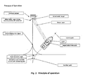
- Fig. 2 schematically shows the working principle of the automatic mooring system.
- the method of interception of obstacles in the docking area and the automatic approach to the quay consists in the fulfilment of two anti-collision bands all around the shape on the surface of the water of the vessel, suitable to detect the obstacles during the low speed approach, as shown in Fig. 3 a.
- the ultrasonic sensors array fulfil a first level anti-collision band, all around the shape on the surface of the water of the vessel and represents the group of sensors suitable to provide the most sharp and stable signals for the relative positioning of the vessel.
- the laser sensors group instead, is used to provide a second level anti-collision band, suitable to detect obstacles in a wider range (e.g. 20 m), all around the shape of the vessel, in order to set speed and approaching direction, resulting in a immediate reaction of the steering systems
- the beam width of the ultrasonic ray of the first level sensors is able to detect obstacles of any shape and dimension with high precision in their operating range.
- the laser sensors are more directive and permit to fulfil a wider anti-collision band, which takes control during the manoeuvres of approach to the quay (low speed).
- the interaction of the two arrays of sensors allows to define the position and the shapes of any obstacle during the mooring manoeuvres, with absolute fidelity with respect to the reality, providing a tridimensional view which automatically updates in real time during the whole manoeuvre.
- a schematic picture of the dimensions of the anti-collision bands is shown in Fig. 3b.
- gyroscopic electronic sensors allows to sharply establish the bow-stern direction of the vessel with respect to the approach course, providing the adequate feed-back to the electronic central unit, which sets in real time the outputs connected to the steering actuators (power drive systems). Furthermore, such a feed back permits to use the system securely even in difficult atmospheric conditions.
- the approaching course to the quay is defined by means of the detection by the system of a fixed point (target position), established by an electronic "bitt" that is self powered by solar energy.
- the bitt is installed on the quay and is equipped with a short range radio transceiver (WI-FI type).
- WI-FI type short range radio transceiver
- the first information about the position of the vessel with respect to the mooring point are provided by the difference of the two GPS positions of the vessel and of the bitt (DGPS - differential GPS))
- the GPS signal is used continuously during the whole manoeuvre, but its resolution is not adequate to the mooring operation: its positioning error is compensated by the other signals locally detected by the other arrays of sensors.
- the shape of the electronic bitt fulfils a sharp reference for a further particular laser sensor, which is used for the detection of the azimuth position of the vessel with respect to the approaching course and to provide a reference to the gyroscopic sensors for the feed-back signals to the steering actuators.
- the functional diagram of the electronic "bitt" is shown in Fig. 4.
- the automatic mooring manoeuvre can be anyway performed, in a semi-automatic operating mode.
- the kind of mooring it is possible to select the kind of mooring to be performed:
- the automatic system selects the best course to approach to the quay and engages the auto-pilot mode, with anti-collision system and smooth control of the power of the controlled motors.
- the initialisation of the system is based on a calibration and self-tuning procedure, to be performed in open sea with good atmospheric conditions, that is suitable to define the available manoeuvre dynamics, when the automatic mooring system is engaged: driving force, steering ray as a function of the speed, stop distances, accelerations (whwn the vessel is stopped and as a function of its speed) in all directions, etc.
- driving force steering ray as a function of the speed
- stop distances accelerations (whwn the vessel is stopped and as a function of its speed) in all directions, etc.
- the self-tuning function furthermore, permits to initialise the system as a function of the dimensions and of the displacement of the vessel, of its steering actuators and of the relative positioning of the arrays of ultrasonic and optical sensors.
- the pilot may choose, in a rich visual database, the approach condition closest to the one to be performed, or may select a local map (if available) of the harbour in which the manoeuvre has to be done.
- the preliminary outline conditions have to be selected: kind of mooring, presence of other vessels on the right and/or left side, approximate available room, etc.
- the most relevant data during the whole operation are stored into a database and may be re-used afterwards, if the same manoeuvre will be repeated in similar conditions.
- the database containing the harbour maps may be updated with the better details (e.g. real time satellite maps, internet upgrades, etc.). In this way the system performs a preliminary mooring map, which is gradually detailed on the control screen, as the obstacle detection signals provide data according to the real life conditions, or generating the drawing of obstacle unexpected during the manoeuvre initialisation.
- the system performs a continuous polling at high sampling rate of all the signals provided by the available sensors of position, speed and acceleration, and calculates the forces for the motor shafts necessary to approach the target position.
- the control of the power to the motor shafts is done by means of two electric motors with a power defined according to the dimensions and inertial force of the vessel; the motors are driven by power drive systems which are controlled directly by the electronic central unit. (dosed loop automatic control).
- the advantage of the use of electric motors consists in the improvement of the dynamics for the rotating inversion and in a better control, by means of the power drive systems, on the rotating speed of the propellers.
- the result is a "stronger" transfer function of the actuation of the automatic commands determined by the elaboration of the signals incoming by the position sensors' arrays.
- FIG. 5° A block diagram of the interceptor system functions and of its interaction with the power drive systems is shown in Fig. 5°.
- Fig. 5b shows a drawing of the electro-mechanic group for the insertion of the power drive systems.
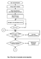
- Fig. 6 shows the flow-chart of the algorithm that embodies the automatic control.
Abstract
- high precision ultrasonic position sensors;
- laser distance sensors;
- gyroscopic sensors;
- DGPS signals (differential GPS - Galileo system ready)
Description
- One of the biggest problems for the pilots of recreational vessels of various displacements and sizes is represented by the difficulties rising from the control of the manoeuvring means during mooring and docking operations in the harbours. In some situations, in fact, very good skill and experience are required while controlling the speed of the engines of the two motors equipped vessels, in order to perform the low speed manoeuvres typical of docking operations in little berthing areas or in presence of a few obstacles (e.g. in the vicinity of other moored vessels). For bigger vessels, furthermore, is very difficult to have visibility and control contemporarily on all the sides of the vessel, which are necessary to avoid collisions with any kind of obstacle between the hull and the berthing deck. The bigger are the dimensions of the vessels, the bigger are such problems. Even more complex is the manoeuvre for vessels equipped with one engine and the rudder (e.g. sailing boats).
In order to dramatically reduce such difficulties, an innovative automatic docking system is proposed, which aids the pilot during the mooring and berthing manoeuvres. - The system presented with the present invention is based on the integration of the following functional units:
- 1. Array of new generation ultrasonic sensors (wireless option)
- 2. Array of laser sensors (wireless option)
- 3. Array of electronic gyroscopic sensors (wireless option)
- 4. Electronic bitt, installed in the docking quay, self-powered with solar cells
- 5. Electronic data acquisition unit (hardware and software) - equipped with receiver option from wireless sensors - radio link radio with sensors' arrays
- 6. Dedicated radio link radio between electronic on board unit and electronic bitt (radio guide)
- 7. Auxiliary asynchronous electric motors, controlled by variable speed drives
- 8. Power drive system, suitable to drive also other electric motors (e.g. bow thrusters' electric pumps) if available on the vessel equipped with the Automatic Mooring System
- 9. Electro mechanic group for the insertion of the electric motors and the exclusion of main engines
- 10. Interface for other signals available on the vessel (anemometers, GPS, etc.)
- The electronic central unit (5.) is the heart of the whole system, and its block diagram is shown in Fig. 1
- Fig. 2 , on the other hand, schematically shows the working principle of the automatic mooring system.
- The method of interception of obstacles in the docking area and the automatic approach to the quay consists in the fulfilment of two anti-collision bands all around the shape on the surface of the water of the vessel, suitable to detect the obstacles during the low speed approach, as shown in Fig. 3 a.
- The ultrasonic sensors array fulfil a first level anti-collision band, all around the shape on the surface of the water of the vessel and represents the group of sensors suitable to provide the most sharp and stable signals for the relative positioning of the vessel.
- The laser sensors group, instead, is used to provide a second level anti-collision band, suitable to detect obstacles in a wider range (e.g. 20 m), all around the shape of the vessel, in order to set speed and approaching direction, resulting in a immediate reaction of the steering systems
- The beam width of the ultrasonic ray of the first level sensors is able to detect obstacles of any shape and dimension with high precision in their operating range. The laser sensors are more directive and permit to fulfil a wider anti-collision band, which takes control during the manoeuvres of approach to the quay (low speed).
- The interaction of the two arrays of sensors (first and second level) allows to define the position and the shapes of any obstacle during the mooring manoeuvres, with absolute fidelity with respect to the reality, providing a tridimensional view which automatically updates in real time during the whole manoeuvre. A schematic picture of the dimensions of the anti-collision bands is shown in Fig. 3b.
- The use of gyroscopic electronic sensors allows to sharply establish the bow-stern direction of the vessel with respect to the approach course, providing the adequate feed-back to the electronic central unit, which sets in real time the outputs connected to the steering actuators (power drive systems). Furthermore, such a feed back permits to use the system securely even in difficult atmospheric conditions.
- The approaching course to the quay is defined by means of the detection by the system of a fixed point (target position), established by an electronic "bitt" that is self powered by solar energy. The bitt is installed on the quay and is equipped with a short range radio transceiver (WI-FI type). The first information about the position of the vessel with respect to the mooring point are provided by the difference of the two GPS positions of the vessel and of the bitt (DGPS - differential GPS))
- The GPS signal is used continuously during the whole manoeuvre, but its resolution is not adequate to the mooring operation: its positioning error is compensated by the other signals locally detected by the other arrays of sensors.
- The shape of the electronic bitt fulfils a sharp reference for a further particular laser sensor, which is used for the detection of the azimuth position of the vessel with respect to the approaching course and to provide a reference to the gyroscopic sensors for the feed-back signals to the steering actuators. The functional diagram of the electronic "bitt" is shown in Fig. 4.
- When it is not possible to establish any link with an electronic bitt, the automatic mooring manoeuvre can be anyway performed, in a semi-automatic operating mode.
On the basis of the position of the bitt on the quay and of the outline condition of the mooring area as an input of the system, it is possible to select the kind of mooring to be performed: - stem
- bow
- right side
- left side
- The automatic system selects the best course to approach to the quay and engages the auto-pilot mode, with anti-collision system and smooth control of the power of the controlled motors.
- Furthermore it is possible to carefully define the solicitations on the vessel, regarding the driving forces, accelerations (the system is useful in any sailing condition), and to modulate the reactive forces necessary by the actuators. This technique may be refined and customized on the basis of the auxiliary propulsion means, other than the main engines, if they are already available on the vessel (e.g. water jet thrusters).
- The initialisation of the system (first installation) is based on a calibration and self-tuning procedure, to be performed in open sea with good atmospheric conditions, that is suitable to define the available manoeuvre dynamics, when the automatic mooring system is engaged: driving force, steering ray as a function of the speed, stop distances, accelerations (whwn the vessel is stopped and as a function of its speed) in all directions, etc. In this way it is possible to parameterize the steering and driving systems and to set the system in order to perform the mooring manoeuvre anywhere there is enough berthing room.
- The self-tuning function, furthermore, permits to initialise the system as a function of the dimensions and of the displacement of the vessel, of its steering actuators and of the relative positioning of the arrays of ultrasonic and optical sensors.
- As the system is initialised and engaged, the pilot may choose, in a rich visual database, the approach condition closest to the one to be performed, or may select a local map (if available) of the harbour in which the manoeuvre has to be done. The preliminary outline conditions have to be selected: kind of mooring, presence of other vessels on the right and/or left side, approximate available room, etc.
- When the mooring manoeuvre has been successfully finished, the most relevant data during the whole operation are stored into a database and may be re-used afterwards, if the same manoeuvre will be repeated in similar conditions.
The database containing the harbour maps may be updated with the better details (e.g. real time satellite maps, internet upgrades, etc.). In this way the system performs a preliminary mooring map, which is gradually detailed on the control screen, as the obstacle detection signals provide data according to the real life conditions, or generating the drawing of obstacle unexpected during the manoeuvre initialisation. - The system performs a continuous polling at high sampling rate of all the signals provided by the available sensors of position, speed and acceleration, and calculates the forces for the motor shafts necessary to approach the target position.
- The control of the power to the motor shafts is done by means of two electric motors with a power defined according to the dimensions and inertial force of the vessel; the motors are driven by power drive systems which are controlled directly by the electronic central unit. (dosed loop automatic control).
- The advantage of the use of electric motors consists in the improvement of the dynamics for the rotating inversion and in a better control, by means of the power drive systems, on the rotating speed of the propellers. The result is a "stronger" transfer function of the actuation of the automatic commands determined by the elaboration of the signals incoming by the position sensors' arrays.
- A block diagram of the interceptor system functions and of its interaction with the power drive systems is shown in Fig. 5°.
- Fig. 5b shows a drawing of the electro-mechanic group for the insertion of the power drive systems.
- Fig. 6 shows the flow-chart of the algorithm that embodies the automatic control.
Claims (5)
- Automatic mooring system useful to pilot recreational vessels or crafts in a harbour or in a berthing zone to a mooring point, comprising an electronic central unit, which controls a power drive system for driving at least two auxiliary asynchronous electric motors that are connected to the motor shafts of the vessel and that are inserted during the mooring manoeuvres by means of an electro-mechanic group which simultaneously is able to exclude the main engines of the vessel, said electronic central unit including an electronic data acquisition unit which is connected to a target bollard interceptor system for defining an approaching course of the vessel to said mooring point by means of the detection of a plurality of target positions of the vessel established by an electronic bitt that is equipped with a radio transceiver which communicates with a radio transceiver on board of the vessel by means of a radio link, so that each position of the vessel with respect to the mooring point is provided by the difference of the two GPS position signals of the vessel and of the bitt, wherein said electronic data acquisition unit is also connected to a first ultrasonic sensors array, which fulfils a first level anti-collision band around the shape of the vessel, and to a second laser sensors array, which is used to provide a second level anti-collision band having a range wider than the range of said first anti-collision band, the interaction of said first and second sensors arrays allowing to define the position and the shapes of any obstacle during said mooring manoeuvres of the vessel up to said mooring point, providing a three-dimensional view which automatically updates in real time during said mooring manoeuvres.
- Automatic mooring system as claimed in claim 1, characterised in that said electronic control unit is connected to a gyroscopic electronic sensors array, which are provided for establishing a bow-stern direction of the vessel with respect to said target positions of the vessel, providing a feed-back signal to said electronic central unit, which sets in real time the outputs connected to said power drive system.
- Automatic mooring system as claimed in claim 2, characterised in that said electronic bitt is shaped as a bollard ladder target in order to fulfil a reference for said laser sensors, which is used for the detection of the azimuth position of the vessel with respect to said target positions of the vessel and for providing a reference to said gyroscopic sensors for said feed-back signal to the electronic central unit.
- Automatic mooring system as claimed in claim 1,
characterised in that said electronic control unit provides for the selection of preliminary conditions and for the visualization of a local map of said harbour or berthing zone, in which said manoeuvres has to be done. - Automatic mooring system as claimed in claim 1, characterised in that said electronic control unit has a database, in which the harbour maps and data related to said manoeuvres are stored.
Priority Applications (1)
| Application Number | Priority Date | Filing Date | Title |
|---|---|---|---|
| EP07012084A EP1873052B1 (en) | 2006-06-22 | 2007-06-20 | Automatic mooring system |
Applications Claiming Priority (2)
| Application Number | Priority Date | Filing Date | Title |
|---|---|---|---|
| EP06425426 | 2006-06-22 | ||
| EP07012084A EP1873052B1 (en) | 2006-06-22 | 2007-06-20 | Automatic mooring system |
Publications (3)
| Publication Number | Publication Date |
|---|---|
| EP1873052A2 true EP1873052A2 (en) | 2008-01-02 |
| EP1873052A3 EP1873052A3 (en) | 2008-05-21 |
| EP1873052B1 EP1873052B1 (en) | 2009-06-10 |
Family
ID=37487546
Family Applications (1)
| Application Number | Title | Priority Date | Filing Date |
|---|---|---|---|
| EP07012084A Not-in-force EP1873052B1 (en) | 2006-06-22 | 2007-06-20 | Automatic mooring system |
Country Status (4)
| Country | Link |
|---|---|
| EP (1) | EP1873052B1 (en) |
| AT (1) | ATE433410T1 (en) |
| DE (1) | DE602007001263D1 (en) |
| ES (1) | ES2327874T3 (en) |
Cited By (21)
| Publication number | Priority date | Publication date | Assignee | Title |
|---|---|---|---|---|
| WO2012010818A1 (en) * | 2010-07-22 | 2012-01-26 | Auto Ranging And Bearing Solutions Llp | Improvements in proximity detection |
| US8855834B2 (en) | 2011-10-25 | 2014-10-07 | Sauer-Danfoss Inc. | Sensing system for following a stringline |
| EP2978661A4 (en) * | 2013-03-25 | 2016-12-21 | Nauti-Craft Pty Ltd | Stabilising of marine bodies |
| WO2018232377A1 (en) * | 2017-06-16 | 2018-12-20 | FLIR Belgium BVBA | Perimeter ranging sensor systems and methods |
| US10281917B2 (en) | 2010-11-19 | 2019-05-07 | Bradley Tyers | Automatic location placement system |
| EP3689736A1 (en) * | 2019-01-31 | 2020-08-05 | Brunswick Corporation | Marine propulsion control system, method, and user interface for marine vessel docking and launch |
| NO20190367A1 (en) * | 2019-03-18 | 2020-09-21 | Macgregor Norway As | A vessel having a mooring system for automatic mooring to a bollard and a method for mooring |
| US10895802B1 (en) * | 2019-08-13 | 2021-01-19 | Buffalo Automation Group, Inc. | Deep learning and intelligent sensing systems for port operations |
| US10926855B2 (en) | 2018-11-01 | 2021-02-23 | Brunswick Corporation | Methods and systems for controlling low-speed propulsion of a marine vessel |
| US11198494B2 (en) | 2018-11-01 | 2021-12-14 | Brunswick Corporation | Methods and systems for controlling propulsion of a marine vessel to enhance proximity sensing in a marine environment |
| US11257378B2 (en) | 2019-01-31 | 2022-02-22 | Brunswick Corporation | Marine propulsion control system and method |
| US11373537B2 (en) | 2018-12-21 | 2022-06-28 | Brunswick Corporation | Marine propulsion control system and method with collision avoidance override |
| EP3865395A4 (en) * | 2018-10-10 | 2022-07-27 | Yanmar Power Technology Co., Ltd. | Automatic docking device |
| US11403955B2 (en) | 2018-12-14 | 2022-08-02 | Brunswick Corporation | Marine propulsion control system and method with proximity-based velocity limiting |
| US11436927B2 (en) | 2018-11-21 | 2022-09-06 | Brunswick Corporation | Proximity sensing system and method for a marine vessel with automated proximity sensor location estimation |
| US11443637B2 (en) | 2018-11-21 | 2022-09-13 | Brunswick Corporation | Proximity sensing system and method for a marine vessel |
| US11505292B2 (en) | 2014-12-31 | 2022-11-22 | FLIR Belgium BVBA | Perimeter ranging sensor systems and methods |
| US11556130B2 (en) | 2010-11-19 | 2023-01-17 | Maid Ip Holdings Pty/Ltd | Automatic location placement system |
| US11733699B2 (en) | 2017-06-16 | 2023-08-22 | FLIR Belgium BVBA | Ultrasonic perimeter ranging sensor systems and methods |
| US11794865B1 (en) | 2018-11-21 | 2023-10-24 | Brunswick Corporation | Proximity sensing system and method for a marine vessel |
| US11899465B2 (en) | 2014-12-31 | 2024-02-13 | FLIR Belgium BVBA | Autonomous and assisted docking systems and methods |
Families Citing this family (1)
| Publication number | Priority date | Publication date | Assignee | Title |
|---|---|---|---|---|
| CN104297758B (en) * | 2014-08-15 | 2017-06-16 | 大连海事大学 | A kind of auxiliary berthing device and its method based on 2D pulse type laser radars |
Citations (6)
| Publication number | Priority date | Publication date | Assignee | Title |
|---|---|---|---|---|
| US4290043A (en) * | 1979-10-16 | 1981-09-15 | Kaplan Irwin M | Method of and system for detecting marine obstacles |
| DE19754582A1 (en) * | 1997-12-09 | 1999-06-10 | Benedikt Zeyen | Easing task of ship navigation with assistance of hyper reality |
| US6469664B1 (en) * | 1999-10-05 | 2002-10-22 | Honeywell International Inc. | Method, apparatus, and computer program products for alerting surface vessels to hazardous conditions |
| US20030137443A1 (en) * | 2002-01-22 | 2003-07-24 | Rees H Barteld Van | Docking information system for boats |
| US20040153222A1 (en) * | 2003-01-31 | 2004-08-05 | David Puchkoff | Device and method for enabling a mariner to select storm havens |
| US20040221468A1 (en) * | 2003-03-03 | 2004-11-11 | Azimut-Benetti S.P.A. | Apparatus for measuring the instantaneous distance between the stern of a vessel and a fixed structure such as quay, a jetty or a landing stage |
-
2007
- 2007-06-20 AT AT07012084T patent/ATE433410T1/en not_active IP Right Cessation
- 2007-06-20 EP EP07012084A patent/EP1873052B1/en not_active Not-in-force
- 2007-06-20 ES ES07012084T patent/ES2327874T3/en active Active
- 2007-06-20 DE DE602007001263T patent/DE602007001263D1/en active Active
Patent Citations (6)
| Publication number | Priority date | Publication date | Assignee | Title |
|---|---|---|---|---|
| US4290043A (en) * | 1979-10-16 | 1981-09-15 | Kaplan Irwin M | Method of and system for detecting marine obstacles |
| DE19754582A1 (en) * | 1997-12-09 | 1999-06-10 | Benedikt Zeyen | Easing task of ship navigation with assistance of hyper reality |
| US6469664B1 (en) * | 1999-10-05 | 2002-10-22 | Honeywell International Inc. | Method, apparatus, and computer program products for alerting surface vessels to hazardous conditions |
| US20030137443A1 (en) * | 2002-01-22 | 2003-07-24 | Rees H Barteld Van | Docking information system for boats |
| US20040153222A1 (en) * | 2003-01-31 | 2004-08-05 | David Puchkoff | Device and method for enabling a mariner to select storm havens |
| US20040221468A1 (en) * | 2003-03-03 | 2004-11-11 | Azimut-Benetti S.P.A. | Apparatus for measuring the instantaneous distance between the stern of a vessel and a fixed structure such as quay, a jetty or a landing stage |
Cited By (33)
| Publication number | Priority date | Publication date | Assignee | Title |
|---|---|---|---|---|
| GB2496078B (en) * | 2010-07-22 | 2014-11-05 | Guidance Navigation Ltd | Improvements in proximity detection |
| GB2496078A (en) * | 2010-07-22 | 2013-05-01 | Auto Ranging And Bearing Solutions Llp | Improvements in proximity detection |
| WO2012010818A1 (en) * | 2010-07-22 | 2012-01-26 | Auto Ranging And Bearing Solutions Llp | Improvements in proximity detection |
| US11768492B2 (en) | 2010-11-19 | 2023-09-26 | MAI IP Holdings Pty/Ltd | Automatic location placement system |
| US10281917B2 (en) | 2010-11-19 | 2019-05-07 | Bradley Tyers | Automatic location placement system |
| US11774971B2 (en) | 2010-11-19 | 2023-10-03 | Maid Ip Holdings P/L | Automatic location placement system |
| US11029686B2 (en) | 2010-11-19 | 2021-06-08 | Maid Ip Holdings P/L | Automatic location placement system |
| US11556130B2 (en) | 2010-11-19 | 2023-01-17 | Maid Ip Holdings Pty/Ltd | Automatic location placement system |
| US8855834B2 (en) | 2011-10-25 | 2014-10-07 | Sauer-Danfoss Inc. | Sensing system for following a stringline |
| EP2978661A4 (en) * | 2013-03-25 | 2016-12-21 | Nauti-Craft Pty Ltd | Stabilising of marine bodies |
| US9731798B2 (en) | 2013-03-25 | 2017-08-15 | Nauti-Craft Pty Ltd | Stabilising of marine bodies |
| US11899465B2 (en) | 2014-12-31 | 2024-02-13 | FLIR Belgium BVBA | Autonomous and assisted docking systems and methods |
| US11505292B2 (en) | 2014-12-31 | 2022-11-22 | FLIR Belgium BVBA | Perimeter ranging sensor systems and methods |
| WO2018232377A1 (en) * | 2017-06-16 | 2018-12-20 | FLIR Belgium BVBA | Perimeter ranging sensor systems and methods |
| US11733699B2 (en) | 2017-06-16 | 2023-08-22 | FLIR Belgium BVBA | Ultrasonic perimeter ranging sensor systems and methods |
| EP3865395A4 (en) * | 2018-10-10 | 2022-07-27 | Yanmar Power Technology Co., Ltd. | Automatic docking device |
| US10926855B2 (en) | 2018-11-01 | 2021-02-23 | Brunswick Corporation | Methods and systems for controlling low-speed propulsion of a marine vessel |
| US11198494B2 (en) | 2018-11-01 | 2021-12-14 | Brunswick Corporation | Methods and systems for controlling propulsion of a marine vessel to enhance proximity sensing in a marine environment |
| US11904996B2 (en) | 2018-11-01 | 2024-02-20 | Brunswick Corporation | Methods and systems for controlling propulsion of a marine vessel to enhance proximity sensing in a marine environment |
| US11436927B2 (en) | 2018-11-21 | 2022-09-06 | Brunswick Corporation | Proximity sensing system and method for a marine vessel with automated proximity sensor location estimation |
| US11443637B2 (en) | 2018-11-21 | 2022-09-13 | Brunswick Corporation | Proximity sensing system and method for a marine vessel |
| US11794865B1 (en) | 2018-11-21 | 2023-10-24 | Brunswick Corporation | Proximity sensing system and method for a marine vessel |
| US11403955B2 (en) | 2018-12-14 | 2022-08-02 | Brunswick Corporation | Marine propulsion control system and method with proximity-based velocity limiting |
| US11862026B2 (en) | 2018-12-14 | 2024-01-02 | Brunswick Corporation | Marine propulsion control system and method with proximity-based velocity limiting |
| US11373537B2 (en) | 2018-12-21 | 2022-06-28 | Brunswick Corporation | Marine propulsion control system and method with collision avoidance override |
| US11804137B1 (en) | 2018-12-21 | 2023-10-31 | Brunswick Corporation | Marine propulsion control system and method with collision avoidance override |
| EP3689736A1 (en) * | 2019-01-31 | 2020-08-05 | Brunswick Corporation | Marine propulsion control system, method, and user interface for marine vessel docking and launch |
| US11702178B2 (en) | 2019-01-31 | 2023-07-18 | Brunswick Corporation | Marine propulsion control system, method, and user interface for marine vessel docking and launch |
| US11600184B2 (en) | 2019-01-31 | 2023-03-07 | Brunswick Corporation | Marine propulsion control system and method |
| US11257378B2 (en) | 2019-01-31 | 2022-02-22 | Brunswick Corporation | Marine propulsion control system and method |
| NO345183B1 (en) * | 2019-03-18 | 2020-10-26 | Macgregor Norway As | A vessel having a mooring system for automatic mooring to a bollard and a method for mooring |
| NO20190367A1 (en) * | 2019-03-18 | 2020-09-21 | Macgregor Norway As | A vessel having a mooring system for automatic mooring to a bollard and a method for mooring |
| US10895802B1 (en) * | 2019-08-13 | 2021-01-19 | Buffalo Automation Group, Inc. | Deep learning and intelligent sensing systems for port operations |
Also Published As
| Publication number | Publication date |
|---|---|
| DE602007001263D1 (en) | 2009-07-23 |
| ATE433410T1 (en) | 2009-06-15 |
| EP1873052A3 (en) | 2008-05-21 |
| ES2327874T3 (en) | 2009-11-04 |
| EP1873052B1 (en) | 2009-06-10 |
Similar Documents
| Publication | Publication Date | Title |
|---|---|---|
| EP1873052B1 (en) | Automatic mooring system | |
| AU2009298414B2 (en) | Joystick controlled marine maneuvering system | |
| EP2024226B1 (en) | Improvements relating to control of marine vessels | |
| EP2338786B1 (en) | System and method for orienting a marine vessel to minimise pitch or roll | |
| EP2338785B1 (en) | Systems and methods for orienting a marine vessel to enhance available thrust | |
| JP6892775B2 (en) | Ship maneuvering assist system and its ship maneuvering assist device and server | |
| EP1775211A2 (en) | Method for positioning a marine vessel and marine vessel | |
| EP1775212A2 (en) | Method for maneuvering a marine vessel and marine vessel | |
| KR102000155B1 (en) | Autonomous navigation system using ship dynamics model | |
| KR20170096460A (en) | A Drone Having a Converting Structure for Running Under Water | |
| EP3666637B1 (en) | Marine propulsion control system and method with proximity-based velocity limiting | |
| US11904996B2 (en) | Methods and systems for controlling propulsion of a marine vessel to enhance proximity sensing in a marine environment | |
| EP3478563B1 (en) | Tug approach control | |
| CN114466788A (en) | Ship steering support system | |
| CN111801634B (en) | interface unit | |
| US20230049367A1 (en) | Thruster control for a boat | |
| WO2023064384A1 (en) | Context-dependent generation of navigational chart comprising hazards | |
| US11697485B2 (en) | Manoeuvring system for a vessel | |
| RU2809129C1 (en) | Method of guiding, mooring and unmooring sea cargo vessel in autonomous mode and method of operating digital instrumental platform for motion control of group of autonomous towing vessels in port water area | |
| CN110831851A (en) | Method for calibrating marine propulsion unit |
Legal Events
| Date | Code | Title | Description |
|---|---|---|---|
| PUAI | Public reference made under article 153(3) epc to a published international application that has entered the european phase |
Free format text: ORIGINAL CODE: 0009012 |
|
| AK | Designated contracting states |
Kind code of ref document: A2 Designated state(s): AT BE BG CH CY CZ DE DK EE ES FI FR GB GR HU IE IS IT LI LT LU LV MC MT NL PL PT RO SE SI SK TR |
|
| AX | Request for extension of the european patent |
Extension state: AL BA HR MK YU |
|
| PUAL | Search report despatched |
Free format text: ORIGINAL CODE: 0009013 |
|
| AK | Designated contracting states |
Kind code of ref document: A3 Designated state(s): AT BE BG CH CY CZ DE DK EE ES FI FR GB GR HU IE IS IT LI LT LU LV MC MT NL PL PT RO SE SI SK TR |
|
| AX | Request for extension of the european patent |
Extension state: AL BA HR MK RS |
|
| 17P | Request for examination filed |
Effective date: 20081002 |
|
| 17Q | First examination report despatched |
Effective date: 20081030 |
|
| GRAP | Despatch of communication of intention to grant a patent |
Free format text: ORIGINAL CODE: EPIDOSNIGR1 |
|
| AKX | Designation fees paid |
Designated state(s): AT BE BG CH CY CZ DE DK EE ES FI FR GB GR HU IE IS IT LI LT LU LV MC MT NL PL PT RO SE SI SK TR |
|
| GRAS | Grant fee paid |
Free format text: ORIGINAL CODE: EPIDOSNIGR3 |
|
| GRAA | (expected) grant |
Free format text: ORIGINAL CODE: 0009210 |
|
| AK | Designated contracting states |
Kind code of ref document: B1 Designated state(s): AT BE BG CH CY CZ DE DK EE ES FI FR GB GR HU IE IS IT LI LT LU LV MC MT NL PL PT RO SE SI SK TR |
|
| REG | Reference to a national code |
Ref country code: GB Ref legal event code: FG4D |
|
| REG | Reference to a national code |
Ref country code: CH Ref legal event code: EP |
|
| REG | Reference to a national code |
Ref country code: IE Ref legal event code: FG4D |
|
| REF | Corresponds to: |
Ref document number: 602007001263 Country of ref document: DE Date of ref document: 20090723 Kind code of ref document: P |
|
| PG25 | Lapsed in a contracting state [announced via postgrant information from national office to epo] |
Ref country code: FI Free format text: LAPSE BECAUSE OF FAILURE TO SUBMIT A TRANSLATION OF THE DESCRIPTION OR TO PAY THE FEE WITHIN THE PRESCRIBED TIME-LIMIT Effective date: 20090610 Ref country code: AT Free format text: LAPSE BECAUSE OF FAILURE TO SUBMIT A TRANSLATION OF THE DESCRIPTION OR TO PAY THE FEE WITHIN THE PRESCRIBED TIME-LIMIT Effective date: 20090610 Ref country code: LT Free format text: LAPSE BECAUSE OF FAILURE TO SUBMIT A TRANSLATION OF THE DESCRIPTION OR TO PAY THE FEE WITHIN THE PRESCRIBED TIME-LIMIT Effective date: 20090610 |
|
| NLV1 | Nl: lapsed or annulled due to failure to fulfill the requirements of art. 29p and 29m of the patents act | ||
| REG | Reference to a national code |
Ref country code: ES Ref legal event code: FG2A Ref document number: 2327874 Country of ref document: ES Kind code of ref document: T3 |
|
| PG25 | Lapsed in a contracting state [announced via postgrant information from national office to epo] |
Ref country code: PL Free format text: LAPSE BECAUSE OF FAILURE TO SUBMIT A TRANSLATION OF THE DESCRIPTION OR TO PAY THE FEE WITHIN THE PRESCRIBED TIME-LIMIT Effective date: 20090610 Ref country code: NL Free format text: LAPSE BECAUSE OF FAILURE TO SUBMIT A TRANSLATION OF THE DESCRIPTION OR TO PAY THE FEE WITHIN THE PRESCRIBED TIME-LIMIT Effective date: 20090610 Ref country code: LV Free format text: LAPSE BECAUSE OF FAILURE TO SUBMIT A TRANSLATION OF THE DESCRIPTION OR TO PAY THE FEE WITHIN THE PRESCRIBED TIME-LIMIT Effective date: 20090610 Ref country code: SE Free format text: LAPSE BECAUSE OF FAILURE TO SUBMIT A TRANSLATION OF THE DESCRIPTION OR TO PAY THE FEE WITHIN THE PRESCRIBED TIME-LIMIT Effective date: 20090910 Ref country code: SI Free format text: LAPSE BECAUSE OF FAILURE TO SUBMIT A TRANSLATION OF THE DESCRIPTION OR TO PAY THE FEE WITHIN THE PRESCRIBED TIME-LIMIT Effective date: 20090610 |
|
| PG25 | Lapsed in a contracting state [announced via postgrant information from national office to epo] |
Ref country code: CZ Free format text: LAPSE BECAUSE OF FAILURE TO SUBMIT A TRANSLATION OF THE DESCRIPTION OR TO PAY THE FEE WITHIN THE PRESCRIBED TIME-LIMIT Effective date: 20090610 Ref country code: RO Free format text: LAPSE BECAUSE OF FAILURE TO SUBMIT A TRANSLATION OF THE DESCRIPTION OR TO PAY THE FEE WITHIN THE PRESCRIBED TIME-LIMIT Effective date: 20090610 Ref country code: EE Free format text: LAPSE BECAUSE OF FAILURE TO SUBMIT A TRANSLATION OF THE DESCRIPTION OR TO PAY THE FEE WITHIN THE PRESCRIBED TIME-LIMIT Effective date: 20090610 Ref country code: IS Free format text: LAPSE BECAUSE OF FAILURE TO SUBMIT A TRANSLATION OF THE DESCRIPTION OR TO PAY THE FEE WITHIN THE PRESCRIBED TIME-LIMIT Effective date: 20091010 |
|
| PG25 | Lapsed in a contracting state [announced via postgrant information from national office to epo] |
Ref country code: SK Free format text: LAPSE BECAUSE OF FAILURE TO SUBMIT A TRANSLATION OF THE DESCRIPTION OR TO PAY THE FEE WITHIN THE PRESCRIBED TIME-LIMIT Effective date: 20090610 Ref country code: BE Free format text: LAPSE BECAUSE OF FAILURE TO SUBMIT A TRANSLATION OF THE DESCRIPTION OR TO PAY THE FEE WITHIN THE PRESCRIBED TIME-LIMIT Effective date: 20090610 |
|
| PG25 | Lapsed in a contracting state [announced via postgrant information from national office to epo] |
Ref country code: PT Free format text: LAPSE BECAUSE OF FAILURE TO SUBMIT A TRANSLATION OF THE DESCRIPTION OR TO PAY THE FEE WITHIN THE PRESCRIBED TIME-LIMIT Effective date: 20091010 Ref country code: BG Free format text: LAPSE BECAUSE OF FAILURE TO SUBMIT A TRANSLATION OF THE DESCRIPTION OR TO PAY THE FEE WITHIN THE PRESCRIBED TIME-LIMIT Effective date: 20090910 |
|
| PLBE | No opposition filed within time limit |
Free format text: ORIGINAL CODE: 0009261 |
|
| STAA | Information on the status of an ep patent application or granted ep patent |
Free format text: STATUS: NO OPPOSITION FILED WITHIN TIME LIMIT |
|
| PG25 | Lapsed in a contracting state [announced via postgrant information from national office to epo] |
Ref country code: IE Free format text: LAPSE BECAUSE OF NON-PAYMENT OF DUE FEES Effective date: 20090620 Ref country code: DK Free format text: LAPSE BECAUSE OF FAILURE TO SUBMIT A TRANSLATION OF THE DESCRIPTION OR TO PAY THE FEE WITHIN THE PRESCRIBED TIME-LIMIT Effective date: 20090610 |
|
| 26N | No opposition filed |
Effective date: 20100311 |
|
| PG25 | Lapsed in a contracting state [announced via postgrant information from national office to epo] |
Ref country code: GR Free format text: LAPSE BECAUSE OF FAILURE TO SUBMIT A TRANSLATION OF THE DESCRIPTION OR TO PAY THE FEE WITHIN THE PRESCRIBED TIME-LIMIT Effective date: 20090911 |
|
| PG25 | Lapsed in a contracting state [announced via postgrant information from national office to epo] |
Ref country code: IT Free format text: LAPSE BECAUSE OF NON-PAYMENT OF DUE FEES Effective date: 20100620 |
|
| PG25 | Lapsed in a contracting state [announced via postgrant information from national office to epo] |
Ref country code: LU Free format text: LAPSE BECAUSE OF NON-PAYMENT OF DUE FEES Effective date: 20090620 Ref country code: MT Free format text: LAPSE BECAUSE OF FAILURE TO SUBMIT A TRANSLATION OF THE DESCRIPTION OR TO PAY THE FEE WITHIN THE PRESCRIBED TIME-LIMIT Effective date: 20090610 |
|
| PG25 | Lapsed in a contracting state [announced via postgrant information from national office to epo] |
Ref country code: HU Free format text: LAPSE BECAUSE OF FAILURE TO SUBMIT A TRANSLATION OF THE DESCRIPTION OR TO PAY THE FEE WITHIN THE PRESCRIBED TIME-LIMIT Effective date: 20091211 |
|
| PG25 | Lapsed in a contracting state [announced via postgrant information from national office to epo] |
Ref country code: TR Free format text: LAPSE BECAUSE OF FAILURE TO SUBMIT A TRANSLATION OF THE DESCRIPTION OR TO PAY THE FEE WITHIN THE PRESCRIBED TIME-LIMIT Effective date: 20090610 |
|
| PG25 | Lapsed in a contracting state [announced via postgrant information from national office to epo] |
Ref country code: CY Free format text: LAPSE BECAUSE OF FAILURE TO SUBMIT A TRANSLATION OF THE DESCRIPTION OR TO PAY THE FEE WITHIN THE PRESCRIBED TIME-LIMIT Effective date: 20090610 |
|
| REG | Reference to a national code |
Ref country code: CH Ref legal event code: PL |
|
| PG25 | Lapsed in a contracting state [announced via postgrant information from national office to epo] |
Ref country code: LI Free format text: LAPSE BECAUSE OF NON-PAYMENT OF DUE FEES Effective date: 20110630 Ref country code: CH Free format text: LAPSE BECAUSE OF NON-PAYMENT OF DUE FEES Effective date: 20110630 |
|
| REG | Reference to a national code |
Ref country code: FR Ref legal event code: PLFP Year of fee payment: 10 |
|
| REG | Reference to a national code |
Ref country code: FR Ref legal event code: PLFP Year of fee payment: 11 |
|
| REG | Reference to a national code |
Ref country code: FR Ref legal event code: PLFP Year of fee payment: 12 |
|
| PGFP | Annual fee paid to national office [announced via postgrant information from national office to epo] |
Ref country code: IT Payment date: 20190628 Year of fee payment: 13 |
|
| PGFP | Annual fee paid to national office [announced via postgrant information from national office to epo] |
Ref country code: DE Payment date: 20200612 Year of fee payment: 14 Ref country code: MC Payment date: 20200519 Year of fee payment: 14 Ref country code: FR Payment date: 20200630 Year of fee payment: 14 |
|
| PGFP | Annual fee paid to national office [announced via postgrant information from national office to epo] |
Ref country code: GB Payment date: 20200619 Year of fee payment: 14 |
|
| PGFP | Annual fee paid to national office [announced via postgrant information from national office to epo] |
Ref country code: ES Payment date: 20200713 Year of fee payment: 14 |
|
| REG | Reference to a national code |
Ref country code: DE Ref legal event code: R119 Ref document number: 602007001263 Country of ref document: DE |
|
| PG25 | Lapsed in a contracting state [announced via postgrant information from national office to epo] |
Ref country code: MC Free format text: LAPSE BECAUSE OF NON-PAYMENT OF DUE FEES Effective date: 20210630 |
|
| GBPC | Gb: european patent ceased through non-payment of renewal fee |
Effective date: 20210620 |
|
| PG25 | Lapsed in a contracting state [announced via postgrant information from national office to epo] |
Ref country code: GB Free format text: LAPSE BECAUSE OF NON-PAYMENT OF DUE FEES Effective date: 20210620 Ref country code: DE Free format text: LAPSE BECAUSE OF NON-PAYMENT OF DUE FEES Effective date: 20220101 |
|
| PG25 | Lapsed in a contracting state [announced via postgrant information from national office to epo] |
Ref country code: FR Free format text: LAPSE BECAUSE OF NON-PAYMENT OF DUE FEES Effective date: 20210630 |
|
| REG | Reference to a national code |
Ref country code: ES Ref legal event code: FD2A Effective date: 20220829 |
|
| PG25 | Lapsed in a contracting state [announced via postgrant information from national office to epo] |
Ref country code: ES Free format text: LAPSE BECAUSE OF NON-PAYMENT OF DUE FEES Effective date: 20210621 |
|
| PG25 | Lapsed in a contracting state [announced via postgrant information from national office to epo] |
Ref country code: IT Free format text: LAPSE BECAUSE OF NON-PAYMENT OF DUE FEES Effective date: 20200620 |