EP1859908A1 - A container assembly - Google Patents
A container assembly Download PDFInfo
- Publication number
- EP1859908A1 EP1859908A1 EP07252097A EP07252097A EP1859908A1 EP 1859908 A1 EP1859908 A1 EP 1859908A1 EP 07252097 A EP07252097 A EP 07252097A EP 07252097 A EP07252097 A EP 07252097A EP 1859908 A1 EP1859908 A1 EP 1859908A1
- Authority
- EP
- European Patent Office
- Prior art keywords
- container
- assembly
- base
- upper opening
- linkage
- Prior art date
- Legal status (The legal status is an assumption and is not a legal conclusion. Google has not performed a legal analysis and makes no representation as to the accuracy of the status listed.)
- Granted
Links
Images


Classifications
-
- B—PERFORMING OPERATIONS; TRANSPORTING
- B62—LAND VEHICLES FOR TRAVELLING OTHERWISE THAN ON RAILS
- B62B—HAND-PROPELLED VEHICLES, e.g. HAND CARTS OR PERAMBULATORS; SLEDGES
- B62B1/00—Hand carts having only one axis carrying one or more transport wheels; Equipment therefor
- B62B1/10—Hand carts having only one axis carrying one or more transport wheels; Equipment therefor in which the load is intended to be transferred totally to the wheels
- B62B1/12—Hand carts having only one axis carrying one or more transport wheels; Equipment therefor in which the load is intended to be transferred totally to the wheels involving parts being adjustable, collapsible, attachable, detachable, or convertible
-
- B—PERFORMING OPERATIONS; TRANSPORTING
- B25—HAND TOOLS; PORTABLE POWER-DRIVEN TOOLS; MANIPULATORS
- B25H—WORKSHOP EQUIPMENT, e.g. FOR MARKING-OUT WORK; STORAGE MEANS FOR WORKSHOPS
- B25H3/00—Storage means or arrangements for workshops facilitating access to, or handling of, work tools or instruments
- B25H3/02—Boxes
- B25H3/021—Boxes comprising a number of connected storage elements
- B25H3/023—Boxes comprising a number of connected storage elements movable relative to one another for access to their interiors
-
- B—PERFORMING OPERATIONS; TRANSPORTING
- B62—LAND VEHICLES FOR TRAVELLING OTHERWISE THAN ON RAILS
- B62B—HAND-PROPELLED VEHICLES, e.g. HAND CARTS OR PERAMBULATORS; SLEDGES
- B62B1/00—Hand carts having only one axis carrying one or more transport wheels; Equipment therefor
- B62B1/008—Hand carts having only one axis carrying one or more transport wheels; Equipment therefor having a prop or stand for maintaining position
Definitions
- the present invention relates to a container assembly.
- the present invention relates to container assemblies and, more particularly, to rolling container assemblies expandable from a compact configuration to an expanded configuration.
- a container assembly comprising a base container having an upper opening; an upper container mounted in covering relation over said upper opening of said base container; a linkage connecting said upper container to said base container in a manner that allows said upper container to be displaced from said covering relation over said upper opening of said base container, so as to permit access into said base container through said upper opening; a support assembly spaced from the base container when the upper container is displaced from said covering relation over said upper opening of said base container; wheels disposed toward a lower portion of said container assembly; and a handle for rollingly transporting said container assembly on said wheels in a tilted configuration.
- a method of opening or closing a container assembly comprising a base container having an upper opening; an upper container mounted in covering relation over said upper opening of said base container; a linkage connecting said upper container to said base container in a manner that allows said upper container to be displaced from said covering relation over said upper opening of said base container, so as to permit access into said base container through said upper opening and a support assembly spaced from the base container when the upper container is displaced from said covering relation over said upper opening of said base container, the method comprising causing rotation of the linkage to thereby force movement of the upper container relative to the base container, to thereby open or close the base container.
- a container assembly includes a base container that has an upper opening and an upper container mounted in covering relation over the upper opening of the base container.
- a linkage connects the upper container to the base container in a manner that allows the upper container to be displaced from the covering relation over the upper opening of the base container, so as to permit access into the base container through the upper opening.
- a support assembly is spaced from the base container when the upper container is displaced from the covering relation over the upper opening of the base container and wheels are disposed toward a lower portion of the container assembly.
- a handle is provided for rollingly transporting the container assembly on the wheels in a tilted configuration.
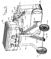
- FIG. 1 A rolling container assembly 10 in accordance with an example of an embodiment of the present invention is shown in FIG. 1.
- the assembly 10 generally includes a base container 20, an upper container 30, and a top container 40.
- a support assembly primarily including a handle 70, a right support leg 72, a left support leg 74, support linkages 75, 77, and wheels 60 provide support for the container assembly 10 and allow for relative movement between the base container 20, the upper container 30, and the top container 40.
- the assembly 10 may be arranged in a compact configuration, as shown in FIGS. 1-2, or the assembly 10 may be arranged in an expanded configuration, as shown in FIGS. 3-9.
- a linkage 50 is mounted to suitable locations on two sides of each of the base container 20, the upper container 30, and the top container 40 to aid in permitting expansion of the assembly 10 from the compact configuration to the expanded configuration.
- the base container 20, the upper container 30, or the top container 40 may contain trays, such as toolbox trays, to aid in organizing and maximizing the space within the interior of any of the containers 20, 30, 40.
- Wheels 60 are mounted in proximity to a lower region of the base container 20 so that the assembly 10 may be tilted and pushed along the ground by a user holding a handle 70. Alternatively, more than two wheels 60 may be mounted to a base region of the assembly 10 such that the assembly 10 need not be tilted to be moved.
- the assembly 10 may be capable of being moved in either the compact configuration or the expanded configuration.
- the wheels 60 are mounted to the lower part of the support legs 72, 74 such that the container assembly 10 may be moved by tilting it back by pulling on the handle 70 and rolling the assembly on the wheels 60.
- wheels 160 may be mounted directly to the base container 20. This arrangement may be advantageous, for example, when the assembly 100 is being expanded or when the base container 20 contains a heavy load.
- the right support leg 72 and the left support leg 74 are provided with ground-engaging posts 180 to provide adequate support when the wheels 160 are moved along with the base container 20.
- the posts 180 may be configured to be foldable upward or outward when the assembly 100 is in the compact configuration so as to allow the wheels 160 to contact the ground.
- the base container 20 includes an upper opening 28 through which access to the inside of the base container 20 is provided, as shown in FIG. 3.
- the base container 20 houses a space within to accommodate any of a variety of items including, but not limited to, tools, hardware, parts, etc.
- the upper opening 28 may be covered by the upper container 30.
- the upper container 30 is displaced such that the upper opening 28 of the base container 20 may be accessible. It should be appreciated that in some embodiments, displacement of the upper container may reveal a removable upper tray or other removable structure that covers the upper opening 28. Nevertheless, such a configuration still permits "access" into the base container 20 through the upper opening 28 of the base container 20 as contemplated herein.
- the base container 20 may further be provided with an arcuate cut-out 24 on each side thereof that is configured to receive each of the wheels 60.
- a ground-engaging surface 26 is provided on the bottom surface of the base container 20 to reduce wear to the assembly 10 from repeated contact with the ground.
- the ground-engaging surface 26 may be made of a hard or durable rubber, plastic, metal, or other suitable material.
- a lower linkage stud 22 may be mounted on each of the sides of the base container 20 for engagement with the linkages 50 to enable expansion of the assembly 10, as will be discussed below.
- the upper container 30 may be located above the base container 20 such that it covers the opening 28 when the assembly 10 is in the compact configuration and permits access to the opening 28 when the assembly 10 is in the expanded configuration.
- the upper container 30 may include a pivot 32 on each of its sides that secures the linkage 50 to the assembly 10 and permits the linkage 50 to rotate about the pivot 32.
- the upper container 30 houses a space within to accommodate any of a variety of items including, but not limited to, tools, hardware, parts, etc.
- the upper container 30 may also be provided with a cover 31 that can be pivotable about hinge 33 to enclose the contents of the upper container 30.
- the upper container 30 further includes a pair of lower rails 38 at an upper region of a front face that interact with a locking plate 35 to prevent expansion of the assembly 10, as discussed below.
- the top container 40 is located above the upper container 30.
- the top container 40 includes an upper linkage stud 46 on each of its sides for engagement with linkages 50 to enable expansion of the assembly 10, as discussed below.
- the top container 40 houses an internal space 49 suitable for accommodating any of a variety of items including, but not limited to, tools, hardware, parts, etc.
- the locking plate 35 is located at a lower region of a front face of the top container 40 and is slidingly received by upper rails 39 for, in conjunction with lower rails 38, preventing or enabling relative displacement between each of the containers 20, 30, 40, as discussed below.
- top container 40 may also be considered as the "upper container” that covers the upper opening of the base container 20.
- the present invention contemplates that there may be intervening structure between the “upper container” and the “base container” as contemplated herein (e.g., also see discussion above regarding the removable tray covering the base container upper opening 28).
- the top container 40 may include a pivotable top cover 44 to permit access to its interior space 49.
- the top cover 44 may be secured in a closed position as shown in FIG. 1 by latches 42. By releasing the latches 42, the top cover 44 may then be pivoted about a hinge 41 to an open position as shown in FIGS. 7-9 (the handle 70 is movable from a first, raised, position as shown in FIGS. 1-2 to a second, lowered, position as shown in FIGS. 4-9, allowing opening clearance for the top cover 44, and is discussed in detail below). In the open position, the top cover 44 may be supported to lay flat such that the top cover 44 is usable as a table or tray.
- Support for the top cover 44 in the vertical force direction is provided by stop surfaces 81 formed on joints 80 associated with the support legs 72, 74 and handle 70.
- Support for the top cover 44 in the horizontal force direction is provided by the stop surface 43, which may be located along an upper region of the top container 40, as shown in FIG. 8.
- the top cover 44 When the top cover 44 is in the open position, it may be configured to receive a tray 45, which may have a handle 47, as shown in FIGS. 7-8.
- the tray 45 has a lip 45a that may ordinarily be received by the ledge 49a disposed about the periphery of an upper region of the internal space 49 of the top container.
- the top cover 44 may include a recess to receive the tray 45 and provide a convenient location to place the tray 45 after it is removed from the top container 40 when accessing objects within the space 49.
- the top container 40 may be configured to be removable from the rolling container assembly 10. As shown in FIG. 6, the top container 40 may be seated in a base frame 48 that includes the upper linkage studs 46 and locking plate 35. In this embodiment, the upper linkage studs 46 attach the base frame 48 to the upper container 30 and the base container 20 via the linkage 50, and a bracket 71 attaches the base frame 48 to the support legs 72, 74. Thus, in this embodiment, any elements that were described as being attached the top container 40 to the container assembly 10 in the previously described embodiment (in which the top container 40 is not removed) are located on the base frame 48, freeing the top container 40 for removal from the container assembly 10 as shown in FIG. 6.
- the top cover 44 may be provided with a handle (not shown) on its top surface to aid in removing the top container 40 from the base frame 48.
- the container assembly 10 may include means to lock the top container 40 in its seated position on the base frame 48. Such locking means may be incorporated into the locking plate 35 mechanism or may comprise a separate locking mechanism, such as latches located on the base frame 48.
- the rolling container assembly 10 of the present invention includes a support assembly that supports, controls, and guides the assembly 10 during expansion and compaction and in each of its final and transient positions.
- the assembly 10 further includes a handle 70, which includes right and left extension legs 82, that enables a user to maneuver the assembly 10.
- the support assembly generally includes right support leg 72, left support leg 74, bracket 71, extension links 75, 77, and guide channel 34. It should be appreciated that numerous arrangements for a support assembly to support the containers when in an expanded cantilevered configuration can be provided.
- the bracket 71 is secured to the top container 40 (or, in the alternative embodiment discussed above, the base frame 48) and the support legs 72, 74 extend from the bracket 71 to a wheel axle 62.
- Extension links 75, 77 are provided to control and guide the movement of the containers 20, 30, 40 during expansion and in each of the positions.
- the extension link 75 extends from the wheel axle 62 to the guide channel 34, as shown in FIGS. 2, 4, and 5.
- the extension link 75 has at one end a guide pin 73 that is configured and sized to follow guide channel 34, thus allowing the extension link 75 to pivot about the guide pin 73 while riding the guide channel 34.
- the extension link 75 may further include a foot pad 78 at an end connected to the wheel axle 62 to assist a user in tilting the assembly 10 when it is desired to be moved.
- the second extension link 77 is pivotally connected at one end to the guide pin 73 and is pivotally connected at another end to a bracket 79 that is secured to the base container 20. When the container assembly 10 is in the compact configuration as shown in FIG. 2, the second extension link 77 may be sized to fit within the first extension link 75 as shown in order to minimize space occupied by the links 75, 77.
- each of the extension links 75, 77 are oriented vertically and the guide pin 73 is at the top end of the guide channel 34.
- the extension links 75, 77 begin to spread out and the guide pin 73 begins to travel downward in the guide channel 34.
- the extension links 75, 77 are oriented at approximately forty-five degree angles with the ground and provide sufficient strength to the assembly 10 by forming trusses with the support legs 72, 74 and the containers 20, 30, 40.
- the guide pin 73 is at the bottom end of the guide channel 34.
- the support assembly When the container assembly 10 is in its expanded configuration (i.e., the upper container 30 is displaced from covering relation to the base container 20) the support assembly is spaced from the base container 20 to better support the cantilevered arrangement of the upper container 30. This is not to say, however, that the support assembly is not spaced from the base container 20 when the container assembly 10 is in the compact configuration. Indeed, in some embodiments, some spacing may be desirable in the compact condition for a larger support footprint.
- the handle 70 is movable between a range of positions having an upper limit, as shown in FIG. 2, and a lower limit, as shown in FIG. 4.
- the support legs 72, 74 are configured to telescopically receive the extension legs 82 of the handle 70 to enable such lowering and extension.
- the bracket 71 includes tabs 76 to lock and release the extension legs 82 from a locking mechanism located within or around the bracket 71. To move the handle 70 up or down, a user squeezes the two tabs 76 together to release the extension legs 82 from the locking mechanism.
- the locking mechanism may be any suitable mechanism known in the art to restrict movement of a telescopically received tube or rod, such as a tension grip, notch and catch, etc.
- the tabs 76 may alternatively be some other release mechanism, such as a button, a single tab, etc.
- the handle 70 When the rolling container assembly 10 is in the compact configuration of FIGS. 1-2 and is desired to be moved, the handle 70 is preferably in an extended position. When the rolling container assembly 10 is in the expanded configuration of FIGS. 4-9, the handle 70 is preferably in the lowered, non-extended position so that the top cover 44 of the top container 40 can be held in an open position and supported by a stop surface 81 located on the joints 80 of the handle 70, as shown in FIGS. 7-8.
- the upper limit of extension for the handle 70 shown in FIGS. 1-2 is merely exemplary and should not be understood to represent a maximum distance of extension.
- the extension legs 82 of the handle 70 may be made up of several series of telescoping tubes such that the handle 70 can be extended beyond what is depicted in Figures.
- the rolling container assembly 10 includes linkages 50 on each side of the assembly 10 in order to maintain relative positions between the containers 20, 30, 40 and to limit movement of the containers 20, 30, 40.
- the linkages 50 are attached to the upper container 30 at pivot 32 such that the linkage 50 rotates about the pivot 32.
- the linkage 50 will rotate counter-clockwise when the assembly 10 moves from a compact configuration (FIG. 2) to an expanded configuration (FIG. 5) and will rotate clockwise when the assembly 10 moves from the expanded configuration (FIG. 5) to the compact configuration (FIG. 2).
- the linkage 50 that is on the left side of the assembly will rotate in opposite directions when viewed from that side.
- the linkage includes lower slot 52 and upper slot 54 that receive the lower linkage stud 22 and the upper linkage stud 46, respectively.
- the linkage 50 is diagonally oriented, and linkage studs 22, 46 are each at the respective ends of the slots 52, 54 that are farthest from the pivot 32.
- the linkage 50 will have rotated to a generally vertical orientation and the linkage studs 22, 46 will have moved inward along the slots 52, 54, toward the pivot 32.
- the linkage 50 will have rotated to a diagonal orientation, approximately ninety degrees from the diagonal orientation of the linkage when in the compact configuration, and the linkage studs 22, 46 will have once again reached the ends of the slots 52, 54 farthest from the pivot 32. Further displacement of the containers is thereby prevented by virtue of the linkage studs 22, 46 reaching the ends of the slots 52, 54 as well as the guide pin 73 reaching the end of the guide channel 34.
- the linkage 50 thus maintains the relative displacement between each pair of adjacent containers 20, 30, 40 to be constant. That is, if the base container 30 moves 6 inches relative to the upper container 20, for example, the linkage 50 assures that the upper container 40 moves 6 inches relative to the top container 30. This concerted action enables smooth operation of the container assembly 10. Further, a user need only apply a force to a single container, such as the base container 20, to effect expansion of the entire assembly 10.
- the rails 38 located in an upper region of the upper container 30 as shown in FIG. 3, are configured to slidingly receive a locking plate 35, which has corresponding slots in its side edges to permit sliding along the rails 38 in the vertical direction (in the frame of reference of the Figures).
- a second set of rails 39 located at a lower region of the top container 40, the rails 38 on the upper container and the locking plate 35 lock the assembly 10 in the compact configuration shown in FIG. 1 and may be unlocked to permit expansion of the assembly 10 to the expanded configuration shown in FIGS. 4-9.
- the locked position of the locking plate 35 is shown in FIG. 1. In this position the assembly 10 is prevented from being expanded because the locking plate 35 restricts lateral displacement between the upper container 30 and the top container 40. Because of the linkage 50 requiring concerted movement between the containers, the prevention of displacement between the upper container 30 and the top container 40 by the locking plate 35 necessarily prevents displacement between any of the containers 20, 30, 40.
- a user may move the locking plate 35 upwards by pulling upward on the surface 37 of the locking plate 35 until it has cleared the rails 38 on the upper container 30.
- the locking plate 35 may have structure that engages with corresponding structure on the rails 39 on the top container 40 to prevent the locking plate 35 from becoming dislodged from the rails 39 or from sliding upward more than necessary, as one of skill in the art will appreciate.
- the assembly 10 is free to be transitioned to the expanded configuration.
- a user may then pull the base container 20 outward from the support legs 72, 74, which in turn displaces the upper container, so that the upper opening 28 of the base container is fully accessible and the cover 31 of the upper container 30 may be pivoted so as to allow access to an internal space of the upper container 30.
- the locking plate 35 may have a top surface 37a to provide an adequate surface area for engagement by the user.
- the locking plate 35 may further have structure that engages with corresponding structure on the upper rails 39 or lower rails 38 in order to prevent the locking plate 35 from being pushed too far, as will be appreciated by one having skill in the art.
Abstract
Description
- The present invention relates to a container assembly.
- In embodiments the present invention relates to container assemblies and, more particularly, to rolling container assemblies expandable from a compact configuration to an expanded configuration.
- Numerous container assemblies are known in the art. However, there is a constant need in the industry to improve upon existing container assemblies by making them more efficient, space reducing, mobile, and/or multi-functional.
- According to a first aspect of the present invention, there is provided a container assembly, comprising a base container having an upper opening; an upper container mounted in covering relation over said upper opening of said base container; a linkage connecting said upper container to said base container in a manner that allows said upper container to be displaced from said covering relation over said upper opening of said base container, so as to permit access into said base container through said upper opening; a support assembly spaced from the base container when the upper container is displaced from said covering relation over said upper opening of said base container; wheels disposed toward a lower portion of said container assembly; and a handle for rollingly transporting said container assembly on said wheels in a tilted configuration.
- According to a second aspect of the present invention, there is provided a method of opening or closing a container assembly comprising a base container having an upper opening; an upper container mounted in covering relation over said upper opening of said base container; a linkage connecting said upper container to said base container in a manner that allows said upper container to be displaced from said covering relation over said upper opening of said base container, so as to permit access into said base container through said upper opening and a support assembly spaced from the base container when the upper container is displaced from said covering relation over said upper opening of said base container, the method comprising causing rotation of the linkage to thereby force movement of the upper container relative to the base container, to thereby open or close the base container.
- A container assembly is provided that includes a base container that has an upper opening and an upper container mounted in covering relation over the upper opening of the base container. A linkage connects the upper container to the base container in a manner that allows the upper container to be displaced from the covering relation over the upper opening of the base container, so as to permit access into the base container through the upper opening. A support assembly is spaced from the base container when the upper container is displaced from the covering relation over the upper opening of the base container and wheels are disposed toward a lower portion of the container assembly. A handle is provided for rollingly transporting the container assembly on the wheels in a tilted configuration.
- Examples of embodiments of the present invention, will now be described in detail with reference to the accompanying drawings, in which:-
- Figure 1 is a perspective front view of a rolling container assembly in a compact configuration, in accordance with an embodiment of the present invention;
- Figure 2 is a perspective rear view of a rolling container assembly in a compact configuration, in accordance with an embodiment of the present invention;
- Figure 3 is a perspective front view of a rolling container assembly in an expanded configuration, in accordance with an embodiment of the present invention;
- Figure 4 is a perspective rear view of a rolling container assembly in an expanded configuration, in accordance with an embodiment of the present invention;
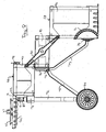
- Figure 5 is a side view of a rolling container assembly in an expanded configuration, in accordance with an embodiment of the present invention;
- Figure 6 is a perspective front view of a rolling container assembly in an expanded configuration including a removable top container, in accordance with an embodiment of the present invention;
- Figure 7 is a perspective front view of a rolling container assembly in an expanded configuration including a pivotable top cover, in accordance with an embodiment of the present invention;
- Figure 8 is a side view of a rolling container assembly in an expanded configuration including a pivotable top cover, in accordance with an embodiment of the present invention; and ..
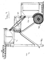
- Figure 9 is a side view of a rolling container assembly in an expanded configuration with wheels mounted to the base container, in accordance with an embodiment of the present invention.
- The present invention will be described with reference to the accompanying drawings. Corresponding reference characters indicate corresponding parts throughout the several views. The description as set out herein illustrates an arrangement of the invention and is not to be construed as limiting the scope of the disclosure in any manner.
- A
rolling container assembly 10 in accordance with an example of an embodiment of the present invention is shown in FIG. 1. Theassembly 10 generally includes abase container 20, anupper container 30, and atop container 40. A support assembly primarily including ahandle 70, aright support leg 72, aleft support leg 74,support linkages 75, 77, andwheels 60 provide support for thecontainer assembly 10 and allow for relative movement between thebase container 20, theupper container 30, and thetop container 40. Theassembly 10 may be arranged in a compact configuration, as shown in FIGS. 1-2, or theassembly 10 may be arranged in an expanded configuration, as shown in FIGS. 3-9. Alinkage 50 is mounted to suitable locations on two sides of each of thebase container 20, theupper container 30, and thetop container 40 to aid in permitting expansion of theassembly 10 from the compact configuration to the expanded configuration. Thebase container 20, theupper container 30, or thetop container 40 may contain trays, such as toolbox trays, to aid in organizing and maximizing the space within the interior of any of thecontainers -
Wheels 60 are mounted in proximity to a lower region of thebase container 20 so that theassembly 10 may be tilted and pushed along the ground by a user holding ahandle 70. Alternatively, more than twowheels 60 may be mounted to a base region of theassembly 10 such that theassembly 10 need not be tilted to be moved. Theassembly 10 may be capable of being moved in either the compact configuration or the expanded configuration. In one embodiment, thewheels 60 are mounted to the lower part of thesupport legs container assembly 10 may be moved by tilting it back by pulling on thehandle 70 and rolling the assembly on thewheels 60. - In another embodiment of a
rolling container assembly 100, shown in FIG. 9,wheels 160 may be mounted directly to thebase container 20. This arrangement may be advantageous, for example, when theassembly 100 is being expanded or when thebase container 20 contains a heavy load. In the embodiment shown in FIG. 9, theright support leg 72 and theleft support leg 74 are provided with ground-engaging posts 180 to provide adequate support when thewheels 160 are moved along with thebase container 20. Theposts 180 may be configured to be foldable upward or outward when theassembly 100 is in the compact configuration so as to allow thewheels 160 to contact the ground. - The
base container 20 includes anupper opening 28 through which access to the inside of thebase container 20 is provided, as shown in FIG. 3. Thebase container 20 houses a space within to accommodate any of a variety of items including, but not limited to, tools, hardware, parts, etc. In the compact configuration, theupper opening 28 may be covered by theupper container 30. In the expanded configuration, theupper container 30 is displaced such that theupper opening 28 of thebase container 20 may be accessible. It should be appreciated that in some embodiments, displacement of the upper container may reveal a removable upper tray or other removable structure that covers theupper opening 28. Nevertheless, such a configuration still permits "access" into thebase container 20 through theupper opening 28 of thebase container 20 as contemplated herein. - The
base container 20 may further be provided with an arcuate cut-out 24 on each side thereof that is configured to receive each of thewheels 60. A ground-engaging surface 26 is provided on the bottom surface of thebase container 20 to reduce wear to theassembly 10 from repeated contact with the ground. The ground-engaging surface 26 may be made of a hard or durable rubber, plastic, metal, or other suitable material. Alower linkage stud 22 may be mounted on each of the sides of thebase container 20 for engagement with thelinkages 50 to enable expansion of theassembly 10, as will be discussed below. - The
upper container 30 may be located above thebase container 20 such that it covers theopening 28 when theassembly 10 is in the compact configuration and permits access to theopening 28 when theassembly 10 is in the expanded configuration. Theupper container 30 may include apivot 32 on each of its sides that secures thelinkage 50 to theassembly 10 and permits thelinkage 50 to rotate about thepivot 32. Theupper container 30 houses a space within to accommodate any of a variety of items including, but not limited to, tools, hardware, parts, etc. Theupper container 30 may also be provided with acover 31 that can be pivotable about hinge 33 to enclose the contents of theupper container 30. Theupper container 30 further includes a pair of lower rails 38 at an upper region of a front face that interact with alocking plate 35 to prevent expansion of theassembly 10, as discussed below. - The
top container 40 is located above theupper container 30. Thetop container 40 includes anupper linkage stud 46 on each of its sides for engagement withlinkages 50 to enable expansion of theassembly 10, as discussed below. Similarly to thebase container 20 and theupper container 30, thetop container 40 houses aninternal space 49 suitable for accommodating any of a variety of items including, but not limited to, tools, hardware, parts, etc. Thelocking plate 35 is located at a lower region of a front face of thetop container 40 and is slidingly received byupper rails 39 for, in conjunction with lower rails 38, preventing or enabling relative displacement between each of thecontainers - It should be appreciated that the
top container 40 may also be considered as the "upper container" that covers the upper opening of thebase container 20. Thus, the present invention contemplates that there may be intervening structure between the "upper container" and the "base container" as contemplated herein (e.g., also see discussion above regarding the removable tray covering the base container upper opening 28). - The
top container 40 may include apivotable top cover 44 to permit access to itsinterior space 49. Thetop cover 44 may be secured in a closed position as shown in FIG. 1 bylatches 42. By releasing thelatches 42, thetop cover 44 may then be pivoted about ahinge 41 to an open position as shown in FIGS. 7-9 (thehandle 70 is movable from a first, raised, position as shown in FIGS. 1-2 to a second, lowered, position as shown in FIGS. 4-9, allowing opening clearance for thetop cover 44, and is discussed in detail below). In the open position, thetop cover 44 may be supported to lay flat such that thetop cover 44 is usable as a table or tray. Support for thetop cover 44 in the vertical force direction is provided bystop surfaces 81 formed onjoints 80 associated with thesupport legs top cover 44 in the horizontal force direction is provided by the stop surface 43, which may be located along an upper region of thetop container 40, as shown in FIG. 8. - When the
top cover 44 is in the open position, it may be configured to receive atray 45, which may have ahandle 47, as shown in FIGS. 7-8. Thetray 45 has a lip 45a that may ordinarily be received by the ledge 49a disposed about the periphery of an upper region of theinternal space 49 of the top container. Thus, thetop cover 44 may include a recess to receive thetray 45 and provide a convenient location to place thetray 45 after it is removed from thetop container 40 when accessing objects within thespace 49. - In one embodiment, the
top container 40 may be configured to be removable from the rollingcontainer assembly 10. As shown in FIG. 6, thetop container 40 may be seated in a base frame 48 that includes theupper linkage studs 46 and lockingplate 35. In this embodiment, theupper linkage studs 46 attach the base frame 48 to theupper container 30 and thebase container 20 via thelinkage 50, and abracket 71 attaches the base frame 48 to thesupport legs top container 40 to thecontainer assembly 10 in the previously described embodiment (in which thetop container 40 is not removed) are located on the base frame 48, freeing thetop container 40 for removal from thecontainer assembly 10 as shown in FIG. 6. Thetop cover 44 may be provided with a handle (not shown) on its top surface to aid in removing thetop container 40 from the base frame 48. Although not shown, thecontainer assembly 10 may include means to lock thetop container 40 in its seated position on the base frame 48. Such locking means may be incorporated into the lockingplate 35 mechanism or may comprise a separate locking mechanism, such as latches located on the base frame 48. - The rolling
container assembly 10 of the present invention includes a support assembly that supports, controls, and guides theassembly 10 during expansion and compaction and in each of its final and transient positions. Theassembly 10 further includes ahandle 70, which includes right and leftextension legs 82, that enables a user to maneuver theassembly 10. - In one, non-limiting example, the support assembly generally includes
right support leg 72, leftsupport leg 74,bracket 71, extension links 75, 77, and guidechannel 34. It should be appreciated that numerous arrangements for a support assembly to support the containers when in an expanded cantilevered configuration can be provided. Thebracket 71 is secured to the top container 40 (or, in the alternative embodiment discussed above, the base frame 48) and thesupport legs bracket 71 to awheel axle 62. Extension links 75, 77 are provided to control and guide the movement of thecontainers extension link 75 extends from thewheel axle 62 to theguide channel 34, as shown in FIGS. 2, 4, and 5. Theextension link 75 has at one end aguide pin 73 that is configured and sized to followguide channel 34, thus allowing theextension link 75 to pivot about theguide pin 73 while riding theguide channel 34. Theextension link 75 may further include afoot pad 78 at an end connected to thewheel axle 62 to assist a user in tilting theassembly 10 when it is desired to be moved. The second extension link 77 is pivotally connected at one end to theguide pin 73 and is pivotally connected at another end to abracket 79 that is secured to thebase container 20. When thecontainer assembly 10 is in the compact configuration as shown in FIG. 2, the second extension link 77 may be sized to fit within thefirst extension link 75 as shown in order to minimize space occupied by thelinks 75, 77. - When the
container assembly 10 is in the compact configuration, as shown in FIG. 2, each of the extension links 75, 77 are oriented vertically and theguide pin 73 is at the top end of theguide channel 34. As the assembly transitions to the expanded configuration, shown in FIGS. 4-5, the extension links 75, 77 begin to spread out and theguide pin 73 begins to travel downward in theguide channel 34. When the final expanded position is reached, the extension links 75, 77 are oriented at approximately forty-five degree angles with the ground and provide sufficient strength to theassembly 10 by forming trusses with thesupport legs containers guide pin 73 is at the bottom end of theguide channel 34. - When the
container assembly 10 is in its expanded configuration (i.e., theupper container 30 is displaced from covering relation to the base container 20) the support assembly is spaced from thebase container 20 to better support the cantilevered arrangement of theupper container 30. This is not to say, however, that the support assembly is not spaced from thebase container 20 when thecontainer assembly 10 is in the compact configuration. Indeed, in some embodiments, some spacing may be desirable in the compact condition for a larger support footprint. - The
handle 70 is movable between a range of positions having an upper limit, as shown in FIG. 2, and a lower limit, as shown in FIG. 4. Thesupport legs extension legs 82 of thehandle 70 to enable such lowering and extension. Thebracket 71 includestabs 76 to lock and release theextension legs 82 from a locking mechanism located within or around thebracket 71. To move thehandle 70 up or down, a user squeezes the twotabs 76 together to release theextension legs 82 from the locking mechanism. The locking mechanism may be any suitable mechanism known in the art to restrict movement of a telescopically received tube or rod, such as a tension grip, notch and catch, etc. Thetabs 76 may alternatively be some other release mechanism, such as a button, a single tab, etc. - When the rolling
container assembly 10 is in the compact configuration of FIGS. 1-2 and is desired to be moved, thehandle 70 is preferably in an extended position. When the rollingcontainer assembly 10 is in the expanded configuration of FIGS. 4-9, thehandle 70 is preferably in the lowered, non-extended position so that thetop cover 44 of thetop container 40 can be held in an open position and supported by astop surface 81 located on thejoints 80 of thehandle 70, as shown in FIGS. 7-8. - It is appreciated that the upper limit of extension for the
handle 70 shown in FIGS. 1-2 is merely exemplary and should not be understood to represent a maximum distance of extension. For example, theextension legs 82 of thehandle 70 may be made up of several series of telescoping tubes such that thehandle 70 can be extended beyond what is depicted in Figures. - The rolling
container assembly 10 includeslinkages 50 on each side of theassembly 10 in order to maintain relative positions between thecontainers containers linkages 50 are attached to theupper container 30 atpivot 32 such that thelinkage 50 rotates about thepivot 32. With respect to thelinkage 50 as shown in FIGS. 2 and 5 that is on the right side of thecontainer assembly 10, thelinkage 50 will rotate counter-clockwise when theassembly 10 moves from a compact configuration (FIG. 2) to an expanded configuration (FIG. 5) and will rotate clockwise when theassembly 10 moves from the expanded configuration (FIG. 5) to the compact configuration (FIG. 2). Naturally, thelinkage 50 that is on the left side of the assembly (not shown) will rotate in opposite directions when viewed from that side. - The linkage includes
lower slot 52 andupper slot 54 that receive thelower linkage stud 22 and theupper linkage stud 46, respectively. In the compact configuration of thecontainer assembly 10 shown in FIGS. 1-2, thelinkage 50 is diagonally oriented, andlinkage studs slots pivot 32. Midway through the transition to the expanded configuration (not shown), thelinkage 50 will have rotated to a generally vertical orientation and thelinkage studs slots pivot 32. When theassembly 10 has reached its final position in the expanded configuration, as shown in FIG. 5, thelinkage 50 will have rotated to a diagonal orientation, approximately ninety degrees from the diagonal orientation of the linkage when in the compact configuration, and thelinkage studs slots pivot 32. Further displacement of the containers is thereby prevented by virtue of thelinkage studs slots guide pin 73 reaching the end of theguide channel 34. During expansion or compaction, thelinkage 50 thus maintains the relative displacement between each pair ofadjacent containers base container 30 moves 6 inches relative to theupper container 20, for example, thelinkage 50 assures that theupper container 40 moves 6 inches relative to thetop container 30. This concerted action enables smooth operation of thecontainer assembly 10. Further, a user need only apply a force to a single container, such as thebase container 20, to effect expansion of theentire assembly 10. - The rails 38, located in an upper region of the
upper container 30 as shown in FIG. 3, are configured to slidingly receive a lockingplate 35, which has corresponding slots in its side edges to permit sliding along the rails 38 in the vertical direction (in the frame of reference of the Figures). In conjunction with a second set ofrails 39 located at a lower region of thetop container 40, the rails 38 on the upper container and the lockingplate 35 lock theassembly 10 in the compact configuration shown in FIG. 1 and may be unlocked to permit expansion of theassembly 10 to the expanded configuration shown in FIGS. 4-9. - The locked position of the locking
plate 35 is shown in FIG. 1. In this position theassembly 10 is prevented from being expanded because the lockingplate 35 restricts lateral displacement between theupper container 30 and thetop container 40. Because of thelinkage 50 requiring concerted movement between the containers, the prevention of displacement between theupper container 30 and thetop container 40 by the lockingplate 35 necessarily prevents displacement between any of thecontainers - When it is desired to move the
assembly 10 to the expanded configuration, a user may move the lockingplate 35 upwards by pulling upward on thesurface 37 of the lockingplate 35 until it has cleared the rails 38 on theupper container 30. The lockingplate 35 may have structure that engages with corresponding structure on therails 39 on thetop container 40 to prevent thelocking plate 35 from becoming dislodged from therails 39 or from sliding upward more than necessary, as one of skill in the art will appreciate. - Once the locking
plate 35 has cleared the rails 38, theassembly 10 is free to be transitioned to the expanded configuration. A user may then pull thebase container 20 outward from thesupport legs upper opening 28 of the base container is fully accessible and thecover 31 of theupper container 30 may be pivoted so as to allow access to an internal space of theupper container 30. - To return the
assembly 10 to the compact configuration, a user may simply push thebase container 20 inward toward thesupport legs locking plate 35 downward to lock theupper container 30 and thetop container 40 together. The lockingplate 35 may have a top surface 37a to provide an adequate surface area for engagement by the user. The lockingplate 35 may further have structure that engages with corresponding structure on theupper rails 39 or lower rails 38 in order to prevent thelocking plate 35 from being pushed too far, as will be appreciated by one having skill in the art. - While specific embodiments have been described above, it will be appreciated that the invention may be practiced otherwise than as described. The descriptions above are intended to be illustrative and not limiting. Thus it will be apparent to one skilled in the art that modifications may be made to the invention as described without departing from the scope of the claims set out below.
- Embodiments of the present invention have been described with particular reference to the examples illustrated. However, it will be appreciated that variations and modifications may be made to the examples described within the scope of the present invention.
Claims (14)
- A container assembly (10), comprising:a base container (20) having an upper opening (28);an upper container (30) mounted in covering relation over said upper opening of said base container;a linkage (50) connecting said upper container (30) to said base container (20) in a manner that allows said upper container to be displaced from said covering relation over said upper opening of said base container, so as to permit access into said base container (20) through said upper opening (28);a support assembly (73, 74, 75, 71, 34) spaced from the base container when the upper container is displaced from said covering relation over said upper opening of said base container;wheels (60) disposed toward a lower portion of said container assembly; anda handle (70) for rollingly transporting said container assembly on said wheels in a tilted configuration.
- A container assembly according to claim 1, further comprising a top container (40) mounted in covering relation over said upper container (30), wherein said linkage (50) is connected to said top container (40) in a manner that allows said top container (40) to be displaced from said covering relation over said upper container.
- A container assembly according to claim 2, wherein said upper container (30) has an upper opening covered by said top container (40) when disposed in covering relation over said upper container (30).
- A container assembly according to claim 2 or 3, wherein said top container (40) has a pivotable cover (44) that can be moved to cover and uncover an upper opening in said top container.
- A container assembly according to claim 1, wherein said wheels (60) are mounted on the support assembly.
- A container assembly (10) according to any of claims 1 to 5, wherein said wheels (60) are mounted on the base container (20).
- A container assembly (20) according to any of claims 1 to 6, wherein a bottom of said base container (20) comprises a ground engaging surface for supporting said container assembly.
- A container assembly according to any of claims 1 to 7, wherein said support assembly is operatively connected with said upper container so as to be automatically moved from a position adjacent to said base container to the position spaced from the base container when the upper container (30) is displaced from said covering relation over said upper opening of said base container (20).
- A container assembly (10) according to any of claims 1 to 8, wherein the support assembly must be manually moved from a position adjacent to said base container (20) to the position spaced from the base container.
- A container assembly according to any of claims 1 to 9, wherein said upper container (30) has a top cover (31) pivotally mounted for opening and closing.
- A container assembly of claim 10, wherein the top cover (31) has a handle, and the upper container can be disconnected from said linkage and separately transported via said handle.
- A container assembly (10) according to claim 4, wherein said pivotable cover (44) has a handle, and wherein said top container can be removed from said linkage so as to be separately transported.
- A container assembly (10) according to claim 4 or 12, wherein the pivotable cover (44) has an opening stop surface that engages a cooperating stop surface on the top container when the cover is pivoted to an open position, so that when pivoted to an open position, said cover is disposed in a horizontal, cantilevered position.
- A container assembly according to claim 4, further comprising a tray (45), said tray (45) movable from a position at which it is disposed at the upper opening in the top container to a position in which is received in a recess in an underside of the cover when the cover is in the horizontal, cantilevered position.
Priority Applications (1)
| Application Number | Priority Date | Filing Date | Title |
|---|---|---|---|
| EP09154771A EP2062701A1 (en) | 2006-05-26 | 2007-05-22 | A container assembly |
Applications Claiming Priority (1)
| Application Number | Priority Date | Filing Date | Title |
|---|---|---|---|
| US11/441,051 US7845653B2 (en) | 2006-05-26 | 2006-05-26 | Transportable containers |
Related Child Applications (1)
| Application Number | Title | Priority Date | Filing Date |
|---|---|---|---|
| EP09154771A Division EP2062701A1 (en) | 2006-05-26 | 2007-05-22 | A container assembly |
Publications (2)
| Publication Number | Publication Date |
|---|---|
| EP1859908A1 true EP1859908A1 (en) | 2007-11-28 |
| EP1859908B1 EP1859908B1 (en) | 2009-04-22 |
Family
ID=38353868
Family Applications (2)
| Application Number | Title | Priority Date | Filing Date |
|---|---|---|---|
| EP07252097A Expired - Fee Related EP1859908B1 (en) | 2006-05-26 | 2007-05-22 | A container assembly |
| EP09154771A Withdrawn EP2062701A1 (en) | 2006-05-26 | 2007-05-22 | A container assembly |
Family Applications After (1)
| Application Number | Title | Priority Date | Filing Date |
|---|---|---|---|
| EP09154771A Withdrawn EP2062701A1 (en) | 2006-05-26 | 2007-05-22 | A container assembly |
Country Status (4)
| Country | Link |
|---|---|
| US (2) | US7845653B2 (en) |
| EP (2) | EP1859908B1 (en) |
| DE (1) | DE602007000932D1 (en) |
| ES (1) | ES2292383T3 (en) |
Cited By (11)
| Publication number | Priority date | Publication date | Assignee | Title |
|---|---|---|---|---|
| WO2008090546A1 (en) * | 2007-01-22 | 2008-07-31 | Keter Plastic Ltd. | Rolling tool cart |
| EP2062701A1 (en) | 2006-05-26 | 2009-05-27 | ZAG Industries, Ltd. | A container assembly |
| EP2289671A3 (en) * | 2009-09-01 | 2011-06-29 | The Stanley Works Israel Ltd. | Rolling container assembly with adjustable storage units |
| WO2014102783A1 (en) * | 2012-12-26 | 2014-07-03 | Keter Plastic Ltd | Cantilever box |
| WO2014125484A1 (en) * | 2013-02-14 | 2014-08-21 | Keter Plastic Ltd. | Toolbox |
| EP3138664A1 (en) | 2015-09-04 | 2017-03-08 | The Stanley Works Israel Ltd. | Tool organiser |
| US9643629B2 (en) | 2009-09-01 | 2017-05-09 | The Stanley Works Isreal Ltd. | Rolling container assembly with adjustable storage units |
| WO2017098511A1 (en) * | 2015-12-10 | 2017-06-15 | Keter Plastic Ltd. | Wheeled container handle assembly |
| USRE47022E1 (en) | 2009-12-11 | 2018-09-04 | The Stanley Works Israel Ltd. | Container |
| US10575417B2 (en) | 2014-09-08 | 2020-02-25 | The Stanley Works Israel Ltd. | Jobsite communications center |
| US11440571B2 (en) * | 2018-06-01 | 2022-09-13 | TANOS GmbH Verpacken Ordnen Präsentieren | Transport device |
Families Citing this family (43)
| Publication number | Priority date | Publication date | Assignee | Title |
|---|---|---|---|---|
| US7150465B2 (en) * | 2003-05-07 | 2006-12-19 | Darling Iii Charles W | Mission adaptable portable cart/utility table arrangement |
| US8523201B2 (en) * | 2008-08-26 | 2013-09-03 | Paul Elijah Allen | Retractable device and utility case |
| US8132819B2 (en) * | 2009-05-15 | 2012-03-13 | The Stanley Works Israel Ltd. | Rolling container assembly with mount structure |
| NL2003332C2 (en) * | 2009-08-05 | 2011-02-08 | Paul Gokkel | FOLDABLE VEHICLE. |
| US8991599B2 (en) * | 2010-12-10 | 2015-03-31 | Roger F. Wilson | Pop-up tool carrier |
| US8844950B2 (en) | 2011-03-04 | 2014-09-30 | Western Industries, Inc. | Storage tote with legs |
| US8657307B2 (en) | 2011-06-22 | 2014-02-25 | The Stanley Works Israel Ltd. | Modular rolling container assembly |
| US8869960B2 (en) * | 2011-07-22 | 2014-10-28 | Ingenious Designs Llc | Expandable multi-compartment luggage |
| US8668209B1 (en) * | 2011-08-18 | 2014-03-11 | Mary Sue Anzivino | Portable modular tool cabinet systems |
| USD701734S1 (en) | 2012-11-09 | 2014-04-01 | Western Industries, Inc. | Storage tote having legs |
| US9555871B2 (en) * | 2012-03-05 | 2017-01-31 | The Boeing Company | Two-surface sandwich structure for accommodating in-plane expansion of one of the surfaces relative to the opposing surface |
| CA149336S (en) * | 2012-07-12 | 2014-09-26 | Stanley Works Israel | Tool box |
| USD732762S1 (en) * | 2012-09-28 | 2015-06-23 | Samsung Electronics Co., Ltd. | Washing machine |
| US9539722B2 (en) | 2012-12-19 | 2017-01-10 | Milwaukee Electric Tool Corporation | Tool storage devices |
| US20140197059A1 (en) * | 2013-01-14 | 2014-07-17 | Keter Plastic Ltd. | Container, toolbox, and cart |
| USD753395S1 (en) * | 2014-03-06 | 2016-04-12 | Keter Plastic Ltd. | Portable tool box |
| CN207189614U (en) | 2014-07-22 | 2018-04-06 | 米沃奇电动工具公司 | Tool storage device |
| CN204014371U (en) | 2014-08-28 | 2014-12-10 | 广州艾卑斯音响设备有限公司 | A kind of hoistable platform cabinet |
| US9550605B1 (en) | 2014-08-29 | 2017-01-24 | Matthew A. Summers | Nesting container assembly |
| US10442568B1 (en) | 2014-08-29 | 2019-10-15 | Matthew A. Summers | Nesting container and nesting container assembly |
| USD770165S1 (en) | 2014-09-30 | 2016-11-01 | Gator Cases, Inc. | Case with pivoting platform |
| CA2978527C (en) | 2015-03-06 | 2023-11-21 | Keter Plastic Ltd. | Container assemblies |
| USD844324S1 (en) | 2015-07-17 | 2019-04-02 | Milwaukee Electric Tool Corporation | Bag |
| USD834817S1 (en) | 2015-07-17 | 2018-12-04 | Milwaukee Electric Tool Corporation | Bag |
| USD810435S1 (en) | 2015-07-17 | 2018-02-20 | Milwaukee Electric Tool Corporation | Bag |
| US10071303B2 (en) | 2015-08-26 | 2018-09-11 | Malibu Innovations, LLC | Mobilized cooler device with fork hanger assembly |
| USD808164S1 (en) | 2015-08-28 | 2018-01-23 | Matthew A. Summers | Container |
| USD1000113S1 (en) | 2015-08-28 | 2023-10-03 | Summers Matthew A | Container |
| US9872547B2 (en) | 2015-11-25 | 2018-01-23 | Milwaukee Electric Tool Corporation | Handle assembly for a case |
| US10039380B2 (en) * | 2016-01-28 | 2018-08-07 | International Vending Management, Inc. | Modular locker structure |
| PL3288719T3 (en) | 2016-05-02 | 2022-07-04 | Keter Home and Garden Products Ltd. | Utility assembly |
| US10807659B2 (en) | 2016-05-27 | 2020-10-20 | Joseph L. Pikulski | Motorized platforms |
| US10208496B2 (en) * | 2016-11-01 | 2019-02-19 | May Manufacturing, LLC | Combining multiple pool components |
| IL274908B2 (en) | 2017-12-20 | 2024-04-01 | Keter Home And Garden Products Ltd | Trolley and mechanical braking system therefor |
| IL257294A (en) | 2018-02-01 | 2018-03-29 | Milwaukee Electric Tool Corp | Coupleable crate |
| IL259990B (en) | 2018-06-13 | 2022-07-01 | Keter Home And Garden Products Ltd | Utility connectivity system |
| IL260225A (en) | 2018-06-24 | 2018-07-31 | Keter Plastic Ltd | Hand truck |
| IL265964A (en) | 2019-04-11 | 2019-07-31 | Milwaukee Electric Tool Corp | Racking system and coupler |
| US10889311B2 (en) * | 2019-05-09 | 2021-01-12 | Steve Madrid | Medical instruments stroller |
| WO2020247791A1 (en) | 2019-06-07 | 2020-12-10 | Milwaukee Electric Tool Corporation | Storage device with handle |
| US11884456B2 (en) | 2020-09-25 | 2024-01-30 | Techtronic Cordless Gp | Tool storage system |
| CA3231247A1 (en) * | 2021-10-11 | 2023-04-20 | Keter Home and Garden Products Ltd. | Wheeled container assembly |
| US11912477B2 (en) | 2022-06-08 | 2024-02-27 | Yeti Coolers, Llc | Container with handle and latching system |
Citations (6)
| Publication number | Priority date | Publication date | Assignee | Title |
|---|---|---|---|---|
| GB938456A (en) * | 1962-05-09 | 1963-10-02 | Draper & Son Ltd B | An improved tool chest or the like |
| DE2852739A1 (en) | 1977-12-14 | 1979-06-28 | Marcel Goeller | WORKSHOP TROLLEY |
| DE8519449U1 (en) * | 1985-07-04 | 1985-09-05 | Rogic, Vladimir, 7000 Stuttgart | Toolbox |
| DE3510307A1 (en) * | 1985-03-22 | 1986-09-25 | KH Wärme & Service AG, Luzern | Servicing device |
| GB2315480A (en) * | 1996-07-23 | 1998-02-04 | Stephen William Stanford | Collapsible storage or tool box |
| US20060021985A1 (en) * | 2004-07-28 | 2006-02-02 | Andrew Jasper | Suspendable tool box |
Family Cites Families (42)
| Publication number | Priority date | Publication date | Assignee | Title |
|---|---|---|---|---|
| US1893526A (en) * | 1929-02-13 | 1933-01-10 | Kennedy Mfg Company | Cantilever kit |
| US1992435A (en) * | 1932-07-01 | 1935-02-26 | Harry H Labadie | Carrying case |
| US2747388A (en) * | 1953-06-15 | 1956-05-29 | Dolar Edward | Covered dish |
| FR1240874A (en) | 1958-12-09 | 1960-09-09 | Dowidat Werke Willi Dowidat | Workshop trolley |
| FR1264534A (en) | 1960-05-09 | 1961-06-23 | Facom Manufacture Francaise De | Machine forming tool trolley for workshop |
| US3383058A (en) * | 1966-06-24 | 1968-05-14 | Globe Tool Eng Co | Stator winding machine |
| US3995926A (en) * | 1976-01-15 | 1976-12-07 | Kessler Sr Clarence J | Flat-opening box |
| DE3045905A1 (en) * | 1980-12-05 | 1982-07-08 | Hazet-Werk Hermann Zerver Gmbh & Co Kg, 5630 Remscheid | MOBILE CONTAINER |
| US4739577A (en) * | 1987-04-13 | 1988-04-26 | Flambeau Corporation | Tackle box |
| US4887837A (en) * | 1987-06-04 | 1989-12-19 | Al-Mar Precision Co. | Carrier for use on beaches, etc. |
| US4820003A (en) * | 1988-04-07 | 1989-04-11 | Lloyd Harold C | Wheeled storage and display cart |
| DE3911096A1 (en) | 1988-04-12 | 1989-10-26 | Vladimir Rogic | Toolbox or the like |
| US5207723A (en) * | 1991-09-24 | 1993-05-04 | Southern Case, Inc. | Portable sectional storage cabinet |
| US5240264A (en) * | 1992-01-27 | 1993-08-31 | Williams Thomas L | Containers on folding wheels and method |
| US5285656A (en) * | 1992-03-06 | 1994-02-15 | Peters Calvin R | Portable cooler chest with expandable wheels and collapsible extension |
| US5378005A (en) * | 1992-10-09 | 1995-01-03 | Norton; George W. | Portable tool truck with diverse tool organizational capability |
| USD349989S (en) * | 1992-11-05 | 1994-08-23 | Shetterly Thomas H | Utility cart |
| US5333408A (en) * | 1993-03-04 | 1994-08-02 | Simmons David O | Tackle box with interior illumination |
| US5452908A (en) * | 1994-04-25 | 1995-09-26 | Bencic; Mirko | Collapsible work stowage cart |
| US5595395A (en) * | 1995-02-09 | 1997-01-21 | Wilson; Carol A. | Bin caddy |
| GB2298190A (en) | 1995-02-21 | 1996-08-28 | 500 Group Inc | Storage case |
| USD395108S (en) * | 1996-07-02 | 1998-06-09 | Pool L Frank | Utility cart |
| US5893572A (en) * | 1996-12-31 | 1999-04-13 | Parks; James E. | Tool caddy |
| US5899467A (en) * | 1997-09-11 | 1999-05-04 | Henkel; Robert R. | Carry-on stroller case |
| IL128303A (en) * | 1998-02-02 | 2002-02-10 | 500 Group Inc | Rolling containers assembly |
| US6347847B1 (en) * | 1998-02-02 | 2002-02-19 | 500 Group Inc. | Rolling containers assembly |
| US6802409B1 (en) * | 1998-03-04 | 2004-10-12 | 500 Group, Inc. | Wheeled luggage and associated devices |
| CA2274028A1 (en) * | 1999-06-04 | 2000-12-04 | Global Contract Limited Partnership | Mobile work station |
| USD437484S1 (en) * | 1999-09-08 | 2001-02-13 | 500 Group Inc. | Rolling workshop |
| US6761366B1 (en) * | 2001-06-04 | 2004-07-13 | Waterloo Industries | Mobile tool carrier |
| ITMN20010037A1 (en) * | 2001-08-27 | 2003-02-27 | Luca Paganini | EXHIBITION TROLLEY FOR COMMERCIAL OPERATORS |
| USD462170S1 (en) * | 2001-09-20 | 2002-09-03 | Shu-Ju Chen | Tool container |
| US6910560B2 (en) * | 2002-05-29 | 2005-06-28 | Jacques M. Dulin | Dual access luggage with orthogonal isolation packing stowage-cell system |
| US6923352B2 (en) * | 2002-12-04 | 2005-08-02 | Luggage America, Inc. | Luggage container with concealed carrying means |
| US6832689B2 (en) * | 2003-02-28 | 2004-12-21 | Yao-Lin Cho | Tool box having expandable drawers |
| US7111852B2 (en) * | 2004-04-29 | 2006-09-26 | Kimball International, Inc. | Utility cart |
| US20060124643A1 (en) * | 2004-12-15 | 2006-06-15 | Markert Brooks R | Dispensing cover with tear strip and living hinge |
| US7306245B1 (en) * | 2005-04-04 | 2007-12-11 | Archie Lowe | Multipurpose work site utility carrier |
| US7503569B2 (en) | 2005-05-16 | 2009-03-17 | Keter Plastic Ltd. | Portable container assembly |
| US7278234B2 (en) * | 2005-08-11 | 2007-10-09 | Steven Marino | Multipurpose tackle box |
| US7845653B2 (en) | 2006-05-26 | 2010-12-07 | Zag Industries Ltd. | Transportable containers |
| EP2114626A1 (en) | 2007-01-22 | 2009-11-11 | Keter Plastic Ltd. | Rolling tool cart |
-
2006
- 2006-05-26 US US11/441,051 patent/US7845653B2/en not_active Expired - Fee Related
-
2007
- 2007-05-22 EP EP07252097A patent/EP1859908B1/en not_active Expired - Fee Related
- 2007-05-22 DE DE602007000932T patent/DE602007000932D1/en active Active
- 2007-05-22 EP EP09154771A patent/EP2062701A1/en not_active Withdrawn
- 2007-05-22 ES ES07252097T patent/ES2292383T3/en active Active
-
2010
- 2010-08-23 US US12/861,700 patent/US7938412B2/en active Active
Patent Citations (6)
| Publication number | Priority date | Publication date | Assignee | Title |
|---|---|---|---|---|
| GB938456A (en) * | 1962-05-09 | 1963-10-02 | Draper & Son Ltd B | An improved tool chest or the like |
| DE2852739A1 (en) | 1977-12-14 | 1979-06-28 | Marcel Goeller | WORKSHOP TROLLEY |
| DE3510307A1 (en) * | 1985-03-22 | 1986-09-25 | KH Wärme & Service AG, Luzern | Servicing device |
| DE8519449U1 (en) * | 1985-07-04 | 1985-09-05 | Rogic, Vladimir, 7000 Stuttgart | Toolbox |
| GB2315480A (en) * | 1996-07-23 | 1998-02-04 | Stephen William Stanford | Collapsible storage or tool box |
| US20060021985A1 (en) * | 2004-07-28 | 2006-02-02 | Andrew Jasper | Suspendable tool box |
Cited By (18)
| Publication number | Priority date | Publication date | Assignee | Title |
|---|---|---|---|---|
| EP2062701A1 (en) | 2006-05-26 | 2009-05-27 | ZAG Industries, Ltd. | A container assembly |
| WO2008090546A1 (en) * | 2007-01-22 | 2008-07-31 | Keter Plastic Ltd. | Rolling tool cart |
| US9643629B2 (en) | 2009-09-01 | 2017-05-09 | The Stanley Works Isreal Ltd. | Rolling container assembly with adjustable storage units |
| EP2289671A3 (en) * | 2009-09-01 | 2011-06-29 | The Stanley Works Israel Ltd. | Rolling container assembly with adjustable storage units |
| US8567796B2 (en) | 2009-09-01 | 2013-10-29 | The Stanley Works Israel Ltd. | Rolling container assembly with adjustable storage units |
| US10787186B2 (en) | 2009-09-01 | 2020-09-29 | The Stanley Works Israel Ltd. | Container assembly with adjustable mount structures |
| US8936258B2 (en) | 2009-09-01 | 2015-01-20 | The Stanley Works Israel Ltd. | Rolling container assembly with adjustable storage units |
| US10106180B2 (en) | 2009-09-01 | 2018-10-23 | The Stanley Works Israel Ltd. | Transportable container |
| USRE47022E1 (en) | 2009-12-11 | 2018-09-04 | The Stanley Works Israel Ltd. | Container |
| WO2014102783A1 (en) * | 2012-12-26 | 2014-07-03 | Keter Plastic Ltd | Cantilever box |
| US9850029B2 (en) | 2012-12-26 | 2017-12-26 | Keter Plastic Ltd. | Cantilever box |
| CN104870146A (en) * | 2012-12-26 | 2015-08-26 | 凯特尔塑料有限公司 | Cantilever box |
| WO2014125484A1 (en) * | 2013-02-14 | 2014-08-21 | Keter Plastic Ltd. | Toolbox |
| US10575417B2 (en) | 2014-09-08 | 2020-02-25 | The Stanley Works Israel Ltd. | Jobsite communications center |
| EP3138664A1 (en) | 2015-09-04 | 2017-03-08 | The Stanley Works Israel Ltd. | Tool organiser |
| WO2017098511A1 (en) * | 2015-12-10 | 2017-06-15 | Keter Plastic Ltd. | Wheeled container handle assembly |
| US11066089B2 (en) | 2015-12-10 | 2021-07-20 | Keter Plastic Ltd. | Wheeled container handle assembly |
| US11440571B2 (en) * | 2018-06-01 | 2022-09-13 | TANOS GmbH Verpacken Ordnen Präsentieren | Transport device |
Also Published As
| Publication number | Publication date |
|---|---|
| EP2062701A1 (en) | 2009-05-27 |
| ES2292383T1 (en) | 2008-03-16 |
| US7938412B2 (en) | 2011-05-10 |
| EP1859908B1 (en) | 2009-04-22 |
| US7845653B2 (en) | 2010-12-07 |
| DE602007000932D1 (en) | 2009-06-04 |
| US20100314856A1 (en) | 2010-12-16 |
| US20070273114A1 (en) | 2007-11-29 |
| ES2292383T3 (en) | 2009-07-06 |
Similar Documents
| Publication | Publication Date | Title |
|---|---|---|
| EP1859908B1 (en) | A container assembly | |
| EP2596920B1 (en) | Modular container assembly | |
| US8191910B2 (en) | Containers and container system | |
| US6685199B2 (en) | Collapsible movable cart | |
| US6149168A (en) | Wheeled tool case | |
| US8162190B2 (en) | Ergonomic lift mechanism for a truck box | |
| US6174124B1 (en) | Load trays for personnel carrying vehicles | |
| US20100052276A1 (en) | Rolling tool cart | |
| US20040195790A1 (en) | Combination toolbox, workbench, dispensing crib and stool | |
| KR20110050510A (en) | Adjustable cleaning cart and method | |
| FR2596738A1 (en) | DEVICE FOR HANDLING A CONTAINER | |
| US9616908B2 (en) | Mobile cart convertible among a plurality of operational modes | |
| US20190233998A1 (en) | Height adjustable sewing machine support and storage system | |
| US5873204A (en) | Cart with multi-position doors | |
| CA2302427A1 (en) | Load trays for personnel carrying vehicles | |
| CN101588897B (en) | Worktable clamping apparatus | |
| US11767165B2 (en) | Bin | |
| CA3231247A1 (en) | Wheeled container assembly | |
| JP4291102B2 (en) | Cargo cradle securing structure in a cargo cradle lifting device | |
| CA2497223C (en) | Sliding tray trunk for a vehicle | |
| JP2022072049A (en) | Structure of mounting container on forklift, and container | |
| US20150259980A1 (en) | Stepladder with tool carrier | |
| WO2001036229A1 (en) | Method of mounting a box and a box system, especially for cars |
Legal Events
| Date | Code | Title | Description |
|---|---|---|---|
| PUAI | Public reference made under article 153(3) epc to a published international application that has entered the european phase |
Free format text: ORIGINAL CODE: 0009012 |
|
| 17P | Request for examination filed |
Effective date: 20070706 |
|
| AK | Designated contracting states |
Kind code of ref document: A1 Designated state(s): AT BE BG CH CY CZ DE DK EE ES FI FR GB GR HU IE IS IT LI LT LU LV MC MT NL PL PT RO SE SI SK TR |
|
| AX | Request for extension of the european patent |
Extension state: AL BA HR MK YU |
|
| RIN1 | Information on inventor provided before grant (corrected) |
Inventor name: KATZ, AMIR |
|
| EL | Fr: translation of claims filed | ||
| 17Q | First examination report despatched |
Effective date: 20080125 |
|
| AKX | Designation fees paid |
Designated state(s): DE ES FR GB IT |
|
| GRAP | Despatch of communication of intention to grant a patent |
Free format text: ORIGINAL CODE: EPIDOSNIGR1 |
|
| GRAS | Grant fee paid |
Free format text: ORIGINAL CODE: EPIDOSNIGR3 |
|
| GRAA | (expected) grant |
Free format text: ORIGINAL CODE: 0009210 |
|
| AK | Designated contracting states |
Kind code of ref document: B1 Designated state(s): DE ES FR GB IT |
|
| REG | Reference to a national code |
Ref country code: GB Ref legal event code: FG4D |
|
| REF | Corresponds to: |
Ref document number: 602007000932 Country of ref document: DE Date of ref document: 20090604 Kind code of ref document: P |
|
| REG | Reference to a national code |
Ref country code: ES Ref legal event code: FG2A Ref document number: 2292383 Country of ref document: ES Kind code of ref document: T3 |
|
| PLBE | No opposition filed within time limit |
Free format text: ORIGINAL CODE: 0009261 |
|
| STAA | Information on the status of an ep patent application or granted ep patent |
Free format text: STATUS: NO OPPOSITION FILED WITHIN TIME LIMIT |
|
| 26N | No opposition filed |
Effective date: 20100125 |
|
| PG25 | Lapsed in a contracting state [announced via postgrant information from national office to epo] |
Ref country code: IT Free format text: LAPSE BECAUSE OF NON-PAYMENT OF DUE FEES Effective date: 20100522 |
|
| REG | Reference to a national code |
Ref country code: FR Ref legal event code: PLFP Year of fee payment: 10 |
|
| PG25 | Lapsed in a contracting state [announced via postgrant information from national office to epo] |
Ref country code: IT Free format text: LAPSE BECAUSE OF NON-PAYMENT OF DUE FEES Effective date: 20160522 |
|
| REG | Reference to a national code |
Ref country code: FR Ref legal event code: PLFP Year of fee payment: 11 |
|
| PG25 | Lapsed in a contracting state [announced via postgrant information from national office to epo] |
Ref country code: IT Free format text: LAPSE BECAUSE OF NON-PAYMENT OF DUE FEES Effective date: 20160522 |
|
| PGRI | Patent reinstated in contracting state [announced from national office to epo] |
Ref country code: IT Effective date: 20170616 |
|
| REG | Reference to a national code |
Ref country code: FR Ref legal event code: PLFP Year of fee payment: 12 |
|
| PGFP | Annual fee paid to national office [announced via postgrant information from national office to epo] |
Ref country code: ES Payment date: 20190425 Year of fee payment: 13 Ref country code: IT Payment date: 20190527 Year of fee payment: 13 |
|
| PGFP | Annual fee paid to national office [announced via postgrant information from national office to epo] |
Ref country code: FR Payment date: 20190410 Year of fee payment: 13 |
|
| PGFP | Annual fee paid to national office [announced via postgrant information from national office to epo] |
Ref country code: DE Payment date: 20200512 Year of fee payment: 14 |
|
| PGFP | Annual fee paid to national office [announced via postgrant information from national office to epo] |
Ref country code: GB Payment date: 20200513 Year of fee payment: 14 |
|
| PG25 | Lapsed in a contracting state [announced via postgrant information from national office to epo] |
Ref country code: FR Free format text: LAPSE BECAUSE OF NON-PAYMENT OF DUE FEES Effective date: 20200531 |
|
| REG | Reference to a national code |
Ref country code: ES Ref legal event code: FD2A Effective date: 20211004 |
|
| PG25 | Lapsed in a contracting state [announced via postgrant information from national office to epo] |
Ref country code: ES Free format text: LAPSE BECAUSE OF NON-PAYMENT OF DUE FEES Effective date: 20200523 |
|
| REG | Reference to a national code |
Ref country code: DE Ref legal event code: R119 Ref document number: 602007000932 Country of ref document: DE |
|
| GBPC | Gb: european patent ceased through non-payment of renewal fee |
Effective date: 20210522 |
|
| PG25 | Lapsed in a contracting state [announced via postgrant information from national office to epo] |
Ref country code: GB Free format text: LAPSE BECAUSE OF NON-PAYMENT OF DUE FEES Effective date: 20210522 Ref country code: DE Free format text: LAPSE BECAUSE OF NON-PAYMENT OF DUE FEES Effective date: 20211201 |
|
| PG25 | Lapsed in a contracting state [announced via postgrant information from national office to epo] |
Ref country code: IT Free format text: LAPSE BECAUSE OF NON-PAYMENT OF DUE FEES Effective date: 20200522 |