EP1857631A1 - Directional control drilling system - Google Patents
Directional control drilling system Download PDFInfo
- Publication number
- EP1857631A1 EP1857631A1 EP06290840A EP06290840A EP1857631A1 EP 1857631 A1 EP1857631 A1 EP 1857631A1 EP 06290840 A EP06290840 A EP 06290840A EP 06290840 A EP06290840 A EP 06290840A EP 1857631 A1 EP1857631 A1 EP 1857631A1
- Authority
- EP
- European Patent Office
- Prior art keywords
- tool
- operating head
- axis
- borehole
- casing
- Prior art date
- Legal status (The legal status is an assumption and is not a legal conclusion. Google has not performed a legal analysis and makes no representation as to the accuracy of the status listed.)
- Withdrawn
Links
Images


Classifications
-
- E—FIXED CONSTRUCTIONS
- E21—EARTH DRILLING; MINING
- E21B—EARTH DRILLING, e.g. DEEP DRILLING; OBTAINING OIL, GAS, WATER, SOLUBLE OR MELTABLE MATERIALS OR A SLURRY OF MINERALS FROM WELLS
- E21B7/00—Special methods or apparatus for drilling
- E21B7/04—Directional drilling
- E21B7/06—Deflecting the direction of boreholes
- E21B7/068—Deflecting the direction of boreholes drilled by a down-hole drilling motor
-
- E—FIXED CONSTRUCTIONS
- E21—EARTH DRILLING; MINING
- E21B—EARTH DRILLING, e.g. DEEP DRILLING; OBTAINING OIL, GAS, WATER, SOLUBLE OR MELTABLE MATERIALS OR A SLURRY OF MINERALS FROM WELLS
- E21B23/00—Apparatus for displacing, setting, locking, releasing, or removing tools, packers or the like in the boreholes or wells
- E21B23/001—Self-propelling systems or apparatus, e.g. for moving tools within the horizontal portion of a borehole
-
- E—FIXED CONSTRUCTIONS
- E21—EARTH DRILLING; MINING
- E21B—EARTH DRILLING, e.g. DEEP DRILLING; OBTAINING OIL, GAS, WATER, SOLUBLE OR MELTABLE MATERIALS OR A SLURRY OF MINERALS FROM WELLS
- E21B4/00—Drives for drilling, used in the borehole
- E21B4/18—Anchoring or feeding in the borehole
-
- E—FIXED CONSTRUCTIONS
- E21—EARTH DRILLING; MINING
- E21B—EARTH DRILLING, e.g. DEEP DRILLING; OBTAINING OIL, GAS, WATER, SOLUBLE OR MELTABLE MATERIALS OR A SLURRY OF MINERALS FROM WELLS
- E21B7/00—Special methods or apparatus for drilling
- E21B7/04—Directional drilling
- E21B7/06—Deflecting the direction of boreholes
- E21B7/067—Deflecting the direction of boreholes with means for locking sections of a pipe or of a guide for a shaft in angular relation, e.g. adjustable bent sub
Definitions
- This invention relates to drilling systems suitable for drilling underground boreholes.
- the invention relates to such drilling systems that allow the trajectory of the borehole to be controlled and deviated as drilling progresses by controlling the direction in which the system drills.
- Drilling using a wireline cable from the bottom-hole drilling assembly (BHA) to the surface offers many benefits in terms of reduction of cost-of-drilling, and reduction of assets and personnel on location. However, with these comes a reduction in the available power available for drilling.
- An example of such a system can be found in one described in WO 2004072437 A (SERVICES PETROLIERS SCHLUMBERGER ET AL) 26.08.2004.
- Such systems typically have separate drive systems for axial drive (thrust, WOB) and rotation of drill bit.
- This decrease in power creates the need to optimize the drilling process by applying a lower-than-conventional force and torque at the bit, and also being able to control the rate of penetration (ROP) or advancement in real time.
- ROP rate of penetration
- Conventional drilling mainly employs two steering mechanisms; surface adjustable motor housings and rotary steerable assemblies (see, for example, US 6092610 (SCHLUMBERGER TECHNOLOGY CORPORATION) 25.07.2000 , but neither are considered as a good match for a low power non-rotating tool.
- a surface adjustable housing requires multiple trips, increasing total time spent on a well and increasing tortuosity.
- Rotary steerable tools rely on the tool rotating for the steering mechanism.
- the present invention aims to provide a drilling system that can control the direction of drilling when used with a non-rotating conveyance such as a wireline cable or coiled tubing.
- a non-rotating conveyance is one which cannot be used to transmit rotation along the well to a downhole drilling assembly.
- This invention provides a well service system, comprising:
- the well service system can comprise a drilling system, wherein the operating head comprises a drill bit.
- the operating head can also comprise a casing milling tool, or a system to set a deflector or whipstock for guiding tools into a lateral borehole.
- the directional control system comprises at least three skids positioned between the tool and the operating head, each skid projecting in a radial direction by an adjustable amount; the projection of each skid being adjusted in use to contact the wall of the borehole and displace the operating head in a desired direction.
- the skids are preferably shaped at their out ends so as to be able to slide along the borehole wall during use.
- the operating head and skids are preferably separated from the tool by a flex section.
- the directional control system comprises a universal joint in the tool through which the operating head is connected, and a direction control mechanism in the tool which is operable to adjust the angle of the operating head axis relative to the tool axis and to adjust the azimuthal direction of the operating head axis.
- a shaft extends between the operating head and the direction control mechanism through the universal joint.
- One embodiment of the direction control mechanism comprises a pair of inter-engaging eccentric rings, one of which connects to the tool and the other of which connects to the shaft, relative rotation of the rings allowing adjustment of the angle of the operating head axis, and co-rotation allowing adjustment of the azimuthal direction of the operating head axis.
- a first, outer ring is connected to the tool, and a second, inner ring that sits inside the first ring and is connected to the shaft.
- the direction control mechanism comprises at least three pistons which act on a head connected to the shaft, the pistons being operable to adjust the angle of the operating head axis relative to the tool axis and to adjust the azimuthal direction of the operating head axis.
- the pistons act in a radial direction to adjust the position of the shaft.
- the direction control mechanism comprises at least three inflatable bladders positioned inside the tool around the shaft, the bladders being inflatable so as to act on the shaft and adjust its position.
- the motor for rotating the operating head is preferably positioned between the operating head and the tool.
- the direction control mechanism comprises separate mechanisms for control of rotation and translation respectively.
- the tool comprises an axial drive system for applying thrust to the operating head.
- a preferred form of axial drive system is a push-pull tractor having pairs of anchors that are alternately deployed as the tractor moves along the borehole.
- the tractor anchors can provide the anchors by which the tool is located in position in the borehole.
- the non-rotating conveyance system can comprise, for example, a wireline cable or coiled tubing.
- a method of opening a window in a casing using a system according to the invention having a milling tool as the operating head comprises:
- this method comprises operating the direction control mechanism to displace the milling tool in axial and azimuthal directions while milling the casing.
- the method may further comprise, following opening of the window, releasing the anchors and withdrawing of the system from the casing.
- One preferred embodiment of the system according to the invention uses controls for the position and direction of a rotating operating head to position the head with respect to an existing window in a casing, to expand anchors to anchor the tool in position, and further to un-anchor and retract and to retrieve a whipstock or a guidestock.
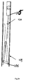
- Figure 1 shows a schematic view of a drilling system according to one embodiment of the invention
- Figure 1 shows the general type of drilling system according to one preferred embodiment of the invention.
- the system includes a downhole drilling unit comprising a rotary drive system 10 carrying a drill bit 12.
- a tool 14 including an axial drive system is positioned behind the rotary drive system 10 and connected to the surface via a control section 16 and a non-rotating conveyance 18 such as a wireline cable or a coiled tubing carrying an electric cable.
- the rotary drive system 10 includes an electric motor by which the drill bit 12 is rotated.
- the power of the motor will depend on its size although for many applications, it may be no more than 3kW.
- the drilling system is run into the borehole 20 until the bit 12 is at the bottom. Drilling proceeds by rotation of the bit 12 using the rotary drive system 10 and advancing the bit into the formation by use of the axial drive system in the tool 14. Control of both is effected by the control system 16 which can in turn be controlled from the surface or can run effectively independently.
- the axial drive system comprises a tractor having pairs of anchors using the push-pull principle. This allows dissociation of coiled tubing pulling and drilling, which helps accurate control of the weight on bit.
- a suitable form of tractor is described in European patent application no. 04292251.8 and PCT/EP04/01167 .
- Figure 1 shows the elements of the drilling system in a linear arrangement suitable for drilling straight boreholes.
- This invention achieves this in one of two ways, known as 'point-the-bit' and 'push-the-bit'.
- FIG. 2 shows a schematic view of such a system according to an embodiment of the invention.
- This embodiment uses an anchor-like assembly 22 below the tool 14 and close to the bit 12 to push the bit 12 in the preferred direction.
- the assembly 22 operates to apply a force that in turn forces the bit 12 to drill in the opposite direction as a function of the force applied.
- the force required using this method may not need to be large, but may require decoupling the moments from the rest of the tool. This can be achieved, for example, by use of a flex section 24 with a low modulus of rigidity.
- This assembly 22 has at least three skids 26 (at 120°) on the external diameter of the tool that can each be extended separately.
- the end of each skid in contact with the formation is shaped so as to slide on the borehole wall while drilling progresses.
- Drilling ahead proceeds by setting the appropriate anchors on the tractor and pushing the drill bit against the reaction provided by the set anchors.
- the skids 26 are each extended by a predetermined amount to provide the desired net force in the required direction.
- the lower pistons 26a are pushed out further (with a higher force) than the upper one 26b, thus pushing the bit 12 upwards (therefore preferentially building angle).
- FIG. 4 shows schematically an embodiment of such a system.
- An upper tool part 30 is similar to that shown in Figure 1 and includes an axial drive system (push-pull tractor) with anchors.
- a lower tool part 32 houses a rotary drilling motor 34, a bit shaft 36, and the bit 38.
- the lower tool part 32 is linked to the upper tool part 30 by a shaft 40 extending through a universal joint (UJ) 42.
- the UJ 42 allows reaction torque to be transmitted from the bit 38 to the upper tool part 30 (and eventually the anchors), and axial thrust (WOB) to be transmitted from the tractor to the bit 38.
- the UJ 42 typically also allows for passage of high-voltage wiring, hydraulic fluid and circulation fluid between the upper tool part 30 and lower tool part 32.
- a direction control mechanism 44 (described in more detail below) is located in the upper tool part 30 and acts on the shaft 40 to direct the bit 38.
- One embodiment of the direction control mechanism comprises a ring-in-ring offsetting mechanism where two offset rings within each other can be rotated to either cancel or add the offsets, therefore allowing for pointing the shaft straight ahead or at any desired angle. The angle then needs to be oriented in the desired direction by rotating the set of rings as an assembly.
- FIG. 6-9 An example of the ring-in-ring mechanism is shown in Figures 6-9 (details of the use of such a system in other applications can be found in US 6092610 (SCHLUMBERGER TECHNOLOGY CORPORATION) 25.07.2000).
- upper tool part 30 is attached rotationally to an outer ring 400 having an offset internal surface 401, this circular internal surface having a centreline at an offset and at an angle to the outside diameter of an inner ring 406 into which is inserted the end of the shaft 40.
- the offsets from the outer and inner rings subtract, which causes the centre of the shaft axis 402 (aligned to internal diameter 407 of the inner ring 406) to be aligned with the longitudinal axis of the upper tool part 30.
- the positioning rings 400, 406 can have any relative rotational positioning between the ring positions of Figures 6 and 7, and the ring positions of Figures 8 and 9.
- the angled relation of the longitudinal axis of the shaft 40 and thus bit 38 with respect to the longitudinal axis of the upper tool part 30 is variable between 0° and a predetermined maximum angle depending upon the relative positions of the positioning rings 400, 406.
- These rings can be rotated with respect to each other by various mechanical or electrical means, such as a geared motor.
- azimuthal direction is determined by rotating both rings together while maintaining their relative positions.
- Another mechanism for offsetting the end of the shaft involves a plurality of radial pistons 50 (at least three for full positional selection) as depicted in Figure 10 and 11.
- the pistons of this mechanism operate in a similar way to the skids of the push-the-bit embodiment described above, the UJ 42 acting to reverse the effect at the bit 38 (pushing the end of the shaft 40 down causes the bit 38 to be raised).
- a variation of this mechanism involves the use of internal inflatable bladders 52 in the place of the pistons as is shown in Figures 12 and 13.
- the inflation and deflation of the bladders 52 allows the shaft 40 to be moved to the desired direction and angle.
- Measurement means may be required to determine the position of the offset since the movement cause by the bladders is not as controllable as with the pistons.
- a further embodiment of a direction control mechanism comprises the use of three axial pistons 54 connected to a head 56, which in turn orients the shaft 40, as is shown in Figures 14 and 15.
- extension or retraction of the pistons 54 to different degrees will have the effect of rotating the head and thus deflecting the shaft 40 (see, for example, Figure 15).
- a typical offset required could be for example 5°, in which case the displacement of the three pistons would typically be in the order of a few millimetres for wireline drilling systems.
- a further embodiment of the direction control mechanism dissociates the two steering dimensions, allowing for better control of each, and easier packaging.
- Figure 16 shows the steering mechanism kinematics chain.
- This mechanism combines a translation and a rotation.
- an orientation sleeve 58 is oriented (0° - 360°) about its axis.
- a bore 60 has been machined in this sleeve with an angle ⁇ .
- the sleeve 58 can be moved forward or backward, using piston 62, to set the shaft inclination.
- the shaft is connected to the tool 30 with an indexed universal joint 42.Such a system presents the advantages to provide a good orientation in all directions (0-360°) and an accurate bend angle selection.
- the point-the-bit approach requires control of the adjustable angle in azimuth, i.e. rotation.
- the rotation mechanism spinsleeve 58
- electrical wiring can simply be lead past the translation mechanism (piston 62) to the rotation mechanism, provided enough length is allowed for a full 360° twist.
- the rotation mechanism 58 can make an infinite number of turns with respect to the tool.
- the rotation mechanism 58 can make an infinite number of turns with respect to the tool. For example, in an embodiment without a slip-ring or wiring going through centre bores (through-wired), if the rotation mechanism is already at 360° and the requirement is to turn another 20° to the right, the rotational mechanism would need to turn *left* by 340° (360-20) to the new desired angle. This would increase the tortuosity of the drilled hole and increase the time required for a minor directional change.
- the management of the orientation and inclination is fully independent and can be driven by separate (electrical and/or hydraulic) systems. Selecting a low inclination angle in the sleeve generates an easy activation management, as the piston 62 can have a long stroke.
- This method has the mechanical advantage to generate a high side force on the lower end by design; allowing to apply a high bit side force, or to lift additional components below the steering mechanism.
- Figure 17 shows a further embodiment of the steering mechanism for use in the invention.
- the mechanism comprises three axial piston and cylinder arrangements 70 (only one shown for clarity) arranged at 120° positions around the tool axis.
- the cylinders are connected to the lower tool part 30 and the pistons arranged to act in an axial direction, each connecting to an associated wedge 72 (of inclination ⁇ ) which acts on the end of the shaft 40 which in turn extends through a universal joint 42 in a similar manner to the embodiments of Figures 12 and 16.
- the orientation of the shaft 40 can be adjusted.
- the drill bit can be replaced by a milling tool 102 to cut window in a casing as depicted in Figures 18-20.
- the system is run into the casing 100.
- the position of the mill 102 is adjusted using the direction control mechanism and the tractor during the milling operation in order to cut the casing to open a window 103 of any desired shape and dimension while following a chosen trajectory and while keeping a depth of cut adapted to the cutting parameters of the mill.
- Figure 20 shows the window 103 cut in the casing (the system is omitted for clarity).
- the direction control mechanism can be used to apply a contact pad against the inner bore of the casing with a controlled force to avoid vibrations and to set a precise depth of cut.
- the drill bit can be replaced by a setting tool in order to install a whipstock or a guidestock as depicted in Figures 21-24.
- the system is run into the casing 100 in front of an open window 103 ( Figure 21).
- the direction control mechanism, the tractor and the rotating head 105 are used to position the bottom of the whipstock 106 at the lower end of the window 103 ( Figure 22).
- the tool is then used to deploy and to anchor the whipstock 106 ( Figure 23) followed by unlatching the whipstock 106 from the lock 104 of the setting tool ( Figure 24).
- the reverse sequence of operation is used to retrieve the whipstock.
- Such a system allows the setting of a guidestock or a whipstock in a precise position and orientation with respect to an already existing window.
- orienting system can be used to machine an internal bore profile or a plug, to remove scale deposits in a cased well, to set a packer, a plug or a valve, to activate a valve or a choke or to position a nozzle to perform cleaning by high pressure or high flow jetting or removal.
- the accurate directional control permitted by the invention can be used to full effect.
Abstract
Description
- This invention relates to drilling systems suitable for drilling underground boreholes. In particular, the invention relates to such drilling systems that allow the trajectory of the borehole to be controlled and deviated as drilling progresses by controlling the direction in which the system drills.
- In the process of drilling underground boreholes, one of the important factors affecting the success of the job is the time spent steering the well in the right direction and landing properly. Frequent changes in trajectory lead to increased hole tortuosity that increases the force required to run in and out of the hole, and also increases the total distance that needs to be drilled to get to the same target.
- Drilling using a wireline cable from the bottom-hole drilling assembly (BHA) to the surface offers many benefits in terms of reduction of cost-of-drilling, and reduction of assets and personnel on location. However, with these comes a reduction in the available power available for drilling. An example of such a system can be found in one described in
WO 2004072437 A (SERVICES PETROLIERS SCHLUMBERGER ET AL) 26.08.2004. Such systems typically have separate drive systems for axial drive (thrust, WOB) and rotation of drill bit. - This decrease in power creates the need to optimize the drilling process by applying a lower-than-conventional force and torque at the bit, and also being able to control the rate of penetration (ROP) or advancement in real time.
- Conventional drilling mainly employs two steering mechanisms; surface adjustable motor housings and rotary steerable assemblies (see, for example,
US 6092610 (SCHLUMBERGER TECHNOLOGY CORPORATION) 25.07.2000 , but neither are considered as a good match for a low power non-rotating tool. A surface adjustable housing requires multiple trips, increasing total time spent on a well and increasing tortuosity. Rotary steerable tools rely on the tool rotating for the steering mechanism. - The present invention aims to provide a drilling system that can control the direction of drilling when used with a non-rotating conveyance such as a wireline cable or coiled tubing. In the context of this inveniton, a non-rotating conveyance is one which cannot be used to transmit rotation along the well to a downhole drilling assembly.
- This invention provides a well service system, comprising:
- a non-rotating conveyance system;
- a tool connected to the non-rotating conveyance system and including anchors by which the tool can be anchored in position when located in a borehole;
- a changeable operating head connected to the tool;
- a motor for rotating the changeable operating head; and
- a directional control system interposed between the tool and the changeable operating head; wherein, in use, with the system located in a borehole, the directional control system can be operated so as to displace the changeable operating head away from the axis of the borehole to perform various operations at the well wall or casing.
- The well service system can comprise a drilling system, wherein the operating head comprises a drill bit. The operating head can also comprise a casing milling tool, or a system to set a deflector or whipstock for guiding tools into a lateral borehole.
- In one embodiment, the directional control system comprises at least three skids positioned between the tool and the operating head, each skid projecting in a radial direction by an adjustable amount; the projection of each skid being adjusted in use to contact the wall of the borehole and displace the operating head in a desired direction. The skids are preferably shaped at their out ends so as to be able to slide along the borehole wall during use.
- In this embodiment, the operating head and skids are preferably separated from the tool by a flex section.
- In another embodiment, the directional control system comprises a universal joint in the tool through which the operating head is connected, and a direction control mechanism in the tool which is operable to adjust the angle of the operating head axis relative to the tool axis and to adjust the azimuthal direction of the operating head axis.
- Preferably, a shaft extends between the operating head and the direction control mechanism through the universal joint.
- One embodiment of the direction control mechanism comprises a pair of inter-engaging eccentric rings, one of which connects to the tool and the other of which connects to the shaft, relative rotation of the rings allowing adjustment of the angle of the operating head axis, and co-rotation allowing adjustment of the azimuthal direction of the operating head axis. In a particularly preferred arrangement, a first, outer ring is connected to the tool, and a second, inner ring that sits inside the first ring and is connected to the shaft.
- In a second embodiment, the direction control mechanism comprises at least three pistons which act on a head connected to the shaft, the pistons being operable to adjust the angle of the operating head axis relative to the tool axis and to adjust the azimuthal direction of the operating head axis.
- In a variant of this second embodiment, the pistons act in a radial direction to adjust the position of the shaft.
- In a third embodiment, the direction control mechanism comprises at least three inflatable bladders positioned inside the tool around the shaft, the bladders being inflatable so as to act on the shaft and adjust its position.
- The motor for rotating the operating head is preferably positioned between the operating head and the tool.
- Preferably, the direction control mechanism comprises separate mechanisms for control of rotation and translation respectively.
- Typically, the tool comprises an axial drive system for applying thrust to the operating head. A preferred form of axial drive system is a push-pull tractor having pairs of anchors that are alternately deployed as the tractor moves along the borehole. The tractor anchors can provide the anchors by which the tool is located in position in the borehole.
- The non-rotating conveyance system can comprise, for example, a wireline cable or coiled tubing.
- The concepts of this invention can apply broadly to a well service system, comprising:
- a non-rotating conveyance system;
- a tool connected to the non-rotating conveyance system and including anchors by which the tool can be anchored in position when located in a borehole;
- a changeable operating head (drill bit, hone, jet head, etc.) connected to the tool;
- a motor for rotating the changeable operating head; and
- a directional control system interposed between the tool and the changeable operating head; wherein, in use, with the system located in a borehole, the directional control system can be operated so as to displace the changeable operating head away from the axis of the borehole to perform various operations at the well wall or casing
- A method of opening a window in a casing using a system according to the invention having a milling tool as the operating head, comprises:
- positioning and anchoring the tool in the casing near to the desired location of the window;
- rotating the milling tool using the motor; and
- operating the direction control mechanism so as to displace the rotating milling head away from the axis of the tool against the casing and open a window of predetermined shape and size.
- Preferably, this method comprises operating the direction control mechanism to displace the milling tool in axial and azimuthal directions while milling the casing. The method may further comprise, following opening of the window, releasing the anchors and withdrawing of the system from the casing.
- One preferred embodiment of the system according to the invention uses controls for the position and direction of a rotating operating head to position the head with respect to an existing window in a casing, to expand anchors to anchor the tool in position, and further to un-anchor and retract and to retrieve a whipstock or a guidestock.
- Figure 1 shows a schematic view of a drilling system according to one embodiment of the invention;
- Figures 2 and 3 show side and cross section views of first embodiment of the invention;
- Figures 4 and 5 show side and cross section views of a second embodiment of the invention;
- Figures 6-9 show sections of a direction control mechanism for use in the embodiment of Figures 4 and 5;
- Figures 10 and 11 show side and cross section views of a third embodiment of the invention;
- Figures 12 and 13 show side and cross section views of a fourth embodiment of the invention;
- Figures 14 and 15 show side and cross section views of a fifth embodiment of the invention;
- Figure 16 shows a schematic view of a sixth embodiment of the invention;
- Figure 17 shows a schematic view of a seventh embodiment of the invention;
- Figures 18-20 show schematic views of an eight embodiment of the invention;
- Figure 19 shows a view on A-A of Figure 18;
- Figure 19 shows the casing in Figures 18 and 19 with the embodiment of the invention removed; and
- Figures 21-24 show schematic views of a ninth embodiment of the invention.
- Figure 1 shows the general type of drilling system according to one preferred embodiment of the invention. The system includes a downhole drilling unit comprising a
rotary drive system 10 carrying adrill bit 12. Atool 14 including an axial drive system is positioned behind therotary drive system 10 and connected to the surface via acontrol section 16 and anon-rotating conveyance 18 such as a wireline cable or a coiled tubing carrying an electric cable. - The
rotary drive system 10 includes an electric motor by which thedrill bit 12 is rotated. The power of the motor will depend on its size although for many applications, it may be no more than 3kW. - In use, the drilling system is run into the borehole 20 until the
bit 12 is at the bottom. Drilling proceeds by rotation of thebit 12 using therotary drive system 10 and advancing the bit into the formation by use of the axial drive system in thetool 14. Control of both is effected by thecontrol system 16 which can in turn be controlled from the surface or can run effectively independently. - In one preferred embodiment, the axial drive system comprises a tractor having pairs of anchors using the push-pull principle. This allows dissociation of coiled tubing pulling and drilling, which helps accurate control of the weight on bit. A suitable form of tractor is described in
European patent application no. 04292251.8 PCT/EP04/01167 . - Figure 1 shows the elements of the drilling system in a linear arrangement suitable for drilling straight boreholes. In order to change the trajectory of the borehole, or to drill a new lateral borehole from an existing borehole, it is necessary to displace the
bit 12 from the axis of thetool 14. This invention achieves this in one of two ways, known as 'point-the-bit' and 'push-the-bit'. - In push-the-bit, an asymmetric force is applied to the drilling system to urge the
drill bit 12 in the desired direction. Figure 2 shows a schematic view of such a system according to an embodiment of the invention. - This embodiment uses an anchor-like assembly 22 below the
tool 14 and close to thebit 12 to push thebit 12 in the preferred direction. The assembly 22 operates to apply a force that in turn forces thebit 12 to drill in the opposite direction as a function of the force applied. The force required using this method may not need to be large, but may require decoupling the moments from the rest of the tool. This can be achieved, for example, by use of aflex section 24 with a low modulus of rigidity. - This assembly 22 has at least three skids 26 (at 120°) on the external diameter of the tool that can each be extended separately. The end of each skid in contact with the formation is shaped so as to slide on the borehole wall while drilling progresses. Drilling ahead proceeds by setting the appropriate anchors on the tractor and pushing the drill bit against the reaction provided by the set anchors. To force the
bit 12 in any specific direction (over a 360° range), theskids 26 are each extended by a predetermined amount to provide the desired net force in the required direction. In Figures 2 and 3, the lower pistons 26a are pushed out further (with a higher force) than the upper one 26b, thus pushing thebit 12 upwards (therefore preferentially building angle). - It will be appreciated that changes can be made to the system described above. For example, more than three skids can be used in the assembly 22. Also, in the embodiment described above, the
rotary drive motor 10 is close to the bit and below theflex section 24. An alternative is to position themotor 10 in thetool 14 above the flex section and drive the bit using a flexible drive shaft. - In the point-the-bit approach, an adjustable angle is created between the tool axis and the drill bit axis. This angle would need to be controlled in both azimuthal direction (preferably 0-360°) and axis angle (preferably at least 0-4°) so as to be able to drill up to a desired dogleg curve (e.g. 120°/100 ft). Figures 4 and 5 show schematically an embodiment of such a system. An
upper tool part 30 is similar to that shown in Figure 1 and includes an axial drive system (push-pull tractor) with anchors. Alower tool part 32 houses arotary drilling motor 34, abit shaft 36, and thebit 38. Thelower tool part 32 is linked to theupper tool part 30 by ashaft 40 extending through a universal joint (UJ) 42. TheUJ 42 allows reaction torque to be transmitted from thebit 38 to the upper tool part 30 (and eventually the anchors), and axial thrust (WOB) to be transmitted from the tractor to thebit 38. TheUJ 42 typically also allows for passage of high-voltage wiring, hydraulic fluid and circulation fluid between theupper tool part 30 andlower tool part 32. A direction control mechanism 44 (described in more detail below) is located in theupper tool part 30 and acts on theshaft 40 to direct thebit 38. - One embodiment of the direction control mechanism comprises a ring-in-ring offsetting mechanism where two offset rings within each other can be rotated to either cancel or add the offsets, therefore allowing for pointing the shaft straight ahead or at any desired angle. The angle then needs to be oriented in the desired direction by rotating the set of rings as an assembly.
- An example of the ring-in-ring mechanism is shown in Figures 6-9 (details of the use of such a system in other applications can be found in
US 6092610 (SCHLUMBERGER TECHNOLOGY CORPORATION) 25.07.2000). In this embodiment,upper tool part 30 is attached rotationally to anouter ring 400 having an offsetinternal surface 401, this circular internal surface having a centreline at an offset and at an angle to the outside diameter of aninner ring 406 into which is inserted the end of theshaft 40. In Figure 6, the offsets from the outer and inner rings subtract, which causes the centre of the shaft axis 402 (aligned to internal diameter 407 of the inner ring 406) to be aligned with the longitudinal axis of theupper tool part 30. Consequently, as depicted in Figures 6 and 7, the centre 405 of the inner ring (shaft) 406 is coincident with thecentre 404 of the outer ring (upper tool part 30) 404, thereby causing the axis of thebit 38 andlower tool part 32 to be aligned with theupper tool part 30 such that the system drills a straight wellbore. - If the
inner ring 406 is rotated 180° relative to theouter ring 400 as shown in Figures 8 and 9, then the resulting geometry of the outer andinner rings shaft axis 402 through point 405 to be at the maximum offset 403 with respect to theouter ring 400, thus locating theshaft 40 at its maximum angle with respect to theupper tool part 30 to drill in a desired direction. To achieve a lesser angle of theshaft 40 with respect to theupper tool part 30 than occurs with the ring setting of Figures 8 and 9, the positioning rings 400, 406 can have any relative rotational positioning between the ring positions of Figures 6 and 7, and the ring positions of Figures 8 and 9. Thus, the angled relation of the longitudinal axis of theshaft 40 and thus bit 38 with respect to the longitudinal axis of theupper tool part 30 is variable between 0° and a predetermined maximum angle depending upon the relative positions of the positioning rings 400, 406. These rings can be rotated with respect to each other by various mechanical or electrical means, such as a geared motor. - Once a desired angle of bit axis has been achieved by relative rotation of the two rings, azimuthal direction is determined by rotating both rings together while maintaining their relative positions.
- Another mechanism for offsetting the end of the shaft involves a plurality of radial pistons 50 (at least three for full positional selection) as depicted in Figure 10 and 11. The pistons of this mechanism operate in a similar way to the skids of the push-the-bit embodiment described above, the
UJ 42 acting to reverse the effect at the bit 38 (pushing the end of theshaft 40 down causes thebit 38 to be raised). - A variation of this mechanism involves the use of internal
inflatable bladders 52 in the place of the pistons as is shown in Figures 12 and 13. The inflation and deflation of thebladders 52 allows theshaft 40 to be moved to the desired direction and angle. Measurement means may be required to determine the position of the offset since the movement cause by the bladders is not as controllable as with the pistons. - A further embodiment of a direction control mechanism comprises the use of three
axial pistons 54 connected to ahead 56, which in turn orients theshaft 40, as is shown in Figures 14 and 15. In this mechanism, extension or retraction of thepistons 54 to different degrees will have the effect of rotating the head and thus deflecting the shaft 40 (see, for example, Figure 15). - By selectively activating (and measuring) the displacement of the three
pistons 54, the direction and inclination of theshaft 40 can be changed. A typical offset required could be for example 5°, in which case the displacement of the three pistons would typically be in the order of a few millimetres for wireline drilling systems. - A further embodiment of the direction control mechanism dissociates the two steering dimensions, allowing for better control of each, and easier packaging. Figure 16 shows the steering mechanism kinematics chain.
- This mechanism combines a translation and a rotation. To define the direction, an
orientation sleeve 58 is oriented (0° - 360°) about its axis. A bore 60 has been machined in this sleeve with an angle α. Once the orientation has been chosen, thesleeve 58 can be moved forward or backward, usingpiston 62, to set the shaft inclination. The shaft is connected to thetool 30 with an indexed universal joint 42.Such a system presents the advantages to provide a good orientation in all directions (0-360°) and an accurate bend angle selection. - It will be recalled that the point-the-bit approach requires control of the adjustable angle in azimuth, i.e. rotation. By limiting the rotation mechanism (sleeve 58) to 0° - 360°, electrical wiring can simply be lead past the translation mechanism (piston 62) to the rotation mechanism, provided enough length is allowed for a full 360° twist. Alternatively, if a `slip-ring' is used to get power and communication around
translation mechanism 62, then therotation mechanism 58 can make an infinite number of turns with respect to the tool. Alternatively, if the electrical wiring is led past the translation mechanism (piston 62) to the rotation mechanism through centre bores inpiston 62, insleeve 58 and inshaft 40, then therotation mechanism 58 can make an infinite number of turns with respect to the tool. For example, in an embodiment without a slip-ring or wiring going through centre bores (through-wired), if the rotation mechanism is already at 360° and the requirement is to turn another 20° to the right, the rotational mechanism would need to turn *left* by 340° (360-20) to the new desired angle. This would increase the tortuosity of the drilled hole and increase the time required for a minor directional change. - The management of the orientation and inclination is fully independent and can be driven by separate (electrical and/or hydraulic) systems. Selecting a low inclination angle in the sleeve generates an easy activation management, as the
piston 62 can have a long stroke. This method has the mechanical advantage to generate a high side force on the lower end by design; allowing to apply a high bit side force, or to lift additional components below the steering mechanism. - Figure 17 shows a further embodiment of the steering mechanism for use in the invention. In this case, the mechanism comprises three axial piston and cylinder arrangements 70 (only one shown for clarity) arranged at 120° positions around the tool axis. The cylinders are connected to the
lower tool part 30 and the pistons arranged to act in an axial direction, each connecting to an associated wedge 72 (of inclination β) which acts on the end of theshaft 40 which in turn extends through a universal joint 42 in a similar manner to the embodiments of Figures 12 and 16. By adjusting the displacement of eachwedge 72, the orientation of theshaft 40 can be adjusted. - With all the embodiments described above, the drill bit can be replaced by a
milling tool 102 to cut window in a casing as depicted in Figures 18-20. The system is run into thecasing 100. The position of themill 102 is adjusted using the direction control mechanism and the tractor during the milling operation in order to cut the casing to open awindow 103 of any desired shape and dimension while following a chosen trajectory and while keeping a depth of cut adapted to the cutting parameters of the mill. Figure 20 shows thewindow 103 cut in the casing (the system is omitted for clarity). - In order to stabilize the tool during the milling process, the direction control mechanism can be used to apply a contact pad against the inner bore of the casing with a controlled force to avoid vibrations and to set a precise depth of cut. Such a system present the advantages of adapting the shape and dimension of the window to any specific need as for providing a smooth transition from the casing to the lateral borehole.
- In another embodiment, the drill bit can be replaced by a setting tool in order to install a whipstock or a guidestock as depicted in Figures 21-24. The system is run into the
casing 100 in front of an open window 103 (Figure 21). The direction control mechanism, the tractor and therotating head 105 are used to position the bottom of thewhipstock 106 at the lower end of the window 103 (Figure 22). The tool is then used to deploy and to anchor the whipstock 106 (Figure 23) followed by unlatching thewhipstock 106 from thelock 104 of the setting tool (Figure 24). The reverse sequence of operation is used to retrieve the whipstock. Such a system allows the setting of a guidestock or a whipstock in a precise position and orientation with respect to an already existing window. - While the embodiments described above relate to some specific applications, it will be understood that the drill bit can be replaced with other operating heads while still delivering a similar effect. For example, orienting system can be used to machine an internal bore profile or a plug, to remove scale deposits in a cased well, to set a packer, a plug or a valve, to activate a valve or a choke or to position a nozzle to perform cleaning by high pressure or high flow jetting or removal. In all cases, the accurate directional control permitted by the invention can be used to full effect.
- Further changes can be made without departing from the scope of the invention.
Claims (22)
- A well service system, comprising:- a non-rotating conveyance system;- a tool connected to the non-rotating conveyance system and including anchors by which the tool can be anchored in position when located in a borehole;- a changeable operating head connected to the tool;- a motor for rotating the changeable operating head; and- a directional control system interposed between the tool and the changeable operating head; wherein, in use, with the system located in a borehole, the directional control system can be operated so as to displace the changeable operating head away from the axis of the borehole to perform various operations at the well wall or casing.
- A well service system as claimed in claim 1, comprising a drilling system, wherein the operating head comprises a drill bit, or a casing milling tool, or a system to set deflector or whipstock for guiding tools into a lateral borehole.
- A system as claimed in claim 1 or 2, wherein the directional control system comprises at least three skids positioned between the tool and the operating head, each skid projecting in a radial direction by an adjustable amount; the projection of each skid being adjusted in use to contact the wall of the borehole and displace the operating head in a desired direction.
- A system as claimed in claim 3, wherein the skids are shaped at their outer ends so as to be able to slide along the borehole wall during use.
- A system as claimed in claim 3 or 4, wherein the operating head and skids are separated from the tool by a flex section.
- A system as claimed in claim 1 or 2, wherein the directional control system comprises a universal joint in the tool through which the operating head is connected, and a direction control mechanism in the tool which is operable to adjust the angle of the operating head axis relative to the tool axis and to adjust the azimuthal direction of the operating head axis.
- A system as claimed in claim 6, further comprising a shaft extending between the operating head and the direction control mechanism through the universal joint.
- A system as claimed in claim 7, wherein the direction control mechanism comprises a pair of inter-engaging eccentric rings, one of which connects to the tool and the other of which connects to the shaft, relative rotation of the rings allowing adjustment of the angle of the operating head axis, and co-rotation allowing adjustment of the azimuthal direction of the operating head axis.
- A system as claimed in claim 8, wherein a first, outer ring is connected to the tool, and a second, inner ring that sits inside the first ring and is connected to the shaft.
- A system as claimed in claim 7, wherein the direction control mechanism comprises at least three pistons which act on a head connected to the shaft, the pistons being operable to adjust the angle of the operating head axis relative to the tool axis and to adjust the azimuthal direction of the operating head axis.
- A system as claimed in claim 10, wherein the pistons act in a radial direction to adjust the position of the shaft.
- A system as claimed in claim 7, wherein the direction control mechanism comprises at least three inflatable bladders positioned inside the tool around the shaft, the bladders being inflatable so as to act on the shaft and adjust its position.
- A system as claimed in any of claims 7-12 , wherein the direction control mechanism comprises separate mechanisms to adjust the angle of the operating head axis relative to the tool axis and to adjust the azimuthal direction of the operating head axis.
- A system as claimed in any preceding claim, wherein the motor for rotating the operating head is positioned between the operating head and the tool.
- A system as claimed in any preceding claim, wherein the tool comprises an axial drive system for applying thrust to the operating head.
- A system as claimed in claim 15, wherein the axial drive system comprises a push-pull tractor having pairs of anchors that are alternately deployed as the tractor moves along the borehole.
- A system as claimed in claim 16, wherein the tractor anchors provide the anchors by which the tool is located in position in the borehole.
- A system as claimed in any preceding claim, wherein the non-rotating conveyance system comprises a wireline cable or coiled tubing.
- A method of opening a window in a casing using a system as claimed in any preceding claim having a milling tool as the operating head, the method comprising:- positioning and anchoring the tool in the casing near to the desired location of the window;- rotating the milling tool using the motor; and- operating the direction control mechanism so as to displace the rotating milling head away from the axis of the tool against the casing and open a window of predetermined shape and size.
- A method as claimed in claim 19, comprising operating the direction control mechanism to displace the milling tool in axial and azimuthal directions while milling the casing.
- A method as claimed in claim 19 or 20, further comprising, following opening of the window, releasing the anchors and withdrawing of the system from the casing.
- A system as claimed in any of claims 1-19, wherein controls for the position and direction of a rotating operating head are used to position the head with respect to an existing window in a casing, to expand anchors and set a whipstock or guidestock to anchor the tool in position, and further to un-anchor and retract and to retrieve the whipstock or guidestock.
Priority Applications (5)
| Application Number | Priority Date | Filing Date | Title |
|---|---|---|---|
| EP06290840A EP1857631A1 (en) | 2006-05-19 | 2006-05-19 | Directional control drilling system |
| PCT/EP2007/004271 WO2007134748A1 (en) | 2006-05-19 | 2007-05-11 | Directional control drilling system |
| CN200780017297.0A CN101443526B (en) | 2006-05-19 | 2007-05-11 | Directional control drilling system |
| CA2650645A CA2650645C (en) | 2006-05-19 | 2007-05-11 | Directional control drilling system |
| US12/301,273 US8191652B2 (en) | 2006-05-19 | 2007-05-11 | Directional control drilling system |
Applications Claiming Priority (1)
| Application Number | Priority Date | Filing Date | Title |
|---|---|---|---|
| EP06290840A EP1857631A1 (en) | 2006-05-19 | 2006-05-19 | Directional control drilling system |
Publications (1)
| Publication Number | Publication Date |
|---|---|
| EP1857631A1 true EP1857631A1 (en) | 2007-11-21 |
Family
ID=37110260
Family Applications (1)
| Application Number | Title | Priority Date | Filing Date |
|---|---|---|---|
| EP06290840A Withdrawn EP1857631A1 (en) | 2006-05-19 | 2006-05-19 | Directional control drilling system |
Country Status (5)
| Country | Link |
|---|---|
| US (1) | US8191652B2 (en) |
| EP (1) | EP1857631A1 (en) |
| CN (1) | CN101443526B (en) |
| CA (1) | CA2650645C (en) |
| WO (1) | WO2007134748A1 (en) |
Cited By (6)
| Publication number | Priority date | Publication date | Assignee | Title |
|---|---|---|---|---|
| WO2008156375A1 (en) * | 2007-06-20 | 2008-12-24 | Tuteedee As | Apparatus for directional control of a drilling tool |
| WO2009085753A3 (en) * | 2007-12-21 | 2009-09-17 | Schlumberger Canada Limited | Steerable drilling system |
| WO2014182175A1 (en) * | 2013-05-10 | 2014-11-13 | Norhard As | Steering-joint device for a rock drilling machine |
| US9371696B2 (en) | 2012-12-28 | 2016-06-21 | Baker Hughes Incorporated | Apparatus and method for drilling deviated wellbores that utilizes an internally tilted drive shaft in a drilling assembly |
| EP2951382A4 (en) * | 2013-01-29 | 2016-11-23 | Services Petroliers Schlumberger | High dogleg steerable tool |
| US11391094B2 (en) * | 2014-06-17 | 2022-07-19 | Petrojet Canada Inc. | Hydraulic drilling systems and methods |
Families Citing this family (25)
| Publication number | Priority date | Publication date | Assignee | Title |
|---|---|---|---|---|
| US6464003B2 (en) | 2000-05-18 | 2002-10-15 | Western Well Tool, Inc. | Gripper assembly for downhole tractors |
| NO333816B1 (en) | 2008-06-05 | 2013-09-23 | Norwegian Hard Rock Drilling As | Device by rock drill. |
| CA2671096C (en) * | 2009-03-26 | 2012-01-10 | Petro-Surge Well Technologies Llc | System and method for longitudinal and lateral jetting in a wellbore |
| EP2341211A1 (en) * | 2009-12-30 | 2011-07-06 | Welltec A/S | Downhole guiding tool |
| US9145736B2 (en) | 2010-07-21 | 2015-09-29 | Baker Hughes Incorporated | Tilted bit rotary steerable drilling system |
| US8925652B2 (en) | 2011-02-28 | 2015-01-06 | Baker Hughes Incorporated | Lateral well drilling apparatus and method |
| WO2012166905A2 (en) * | 2011-06-01 | 2012-12-06 | Vermeer Manufacturing Company | Tunneling apparatus |
| US9187956B2 (en) | 2011-09-27 | 2015-11-17 | Richard Hutton | Point the bit rotary steerable system |
| US9447648B2 (en) | 2011-10-28 | 2016-09-20 | Wwt North America Holdings, Inc | High expansion or dual link gripper |
| GB2496907B (en) * | 2011-11-28 | 2013-10-23 | Innova Drilling And Intervention Ltd | Improved wireline drilling system |
| NL2008061C2 (en) * | 2011-12-30 | 2013-07-03 | Well Engineering Partners Wep B V | Device for anchoring in a casing in a borehole in the ground. |
| US9556678B2 (en) | 2012-05-30 | 2017-01-31 | Penny Technologies S.À R.L. | Drilling system, biasing mechanism and method for directionally drilling a borehole |
| IN2014DN10389A (en) * | 2012-06-12 | 2015-08-14 | Halliburton Energy Services Inc | |
| US9057223B2 (en) * | 2012-06-21 | 2015-06-16 | Schlumberger Technology Corporation | Directional drilling system |
| US9828804B2 (en) * | 2013-10-25 | 2017-11-28 | Schlumberger Technology Corporation | Multi-angle rotary steerable drilling |
| US9488020B2 (en) | 2014-01-27 | 2016-11-08 | Wwt North America Holdings, Inc. | Eccentric linkage gripper |
| WO2015122918A1 (en) * | 2014-02-14 | 2015-08-20 | Halliburton Energy Services Inc. | Drilling shaft deflection device |
| WO2015200390A1 (en) | 2014-06-24 | 2015-12-30 | Pine Tree Gas, Llc | Systems and methods for drilling wellbores having a short radius of curvature |
| US10605005B2 (en) | 2014-12-09 | 2020-03-31 | Schlumberger Technology Corporation | Steerable drill bit system |
| US10697245B2 (en) | 2015-03-24 | 2020-06-30 | Cameron International Corporation | Seabed drilling system |
| US10053914B2 (en) | 2016-01-22 | 2018-08-21 | Baker Hughes, A Ge Company, Llc | Method and application for directional drilling with an asymmetric deflecting bend |
| US9624727B1 (en) | 2016-02-18 | 2017-04-18 | D-Tech (Uk) Ltd. | Rotary bit pushing system |
| US11371288B2 (en) | 2017-05-18 | 2022-06-28 | Halliburton Energy Services, Inc. | Rotary steerable drilling push-the-point-the-bit |
| CN107605402B (en) * | 2017-11-06 | 2019-05-21 | 中煤科工集团西安研究院有限公司 | The broken soft seam flexibility internal control spin orientation drilling system of underground coal mine and drilling method |
| CN109899061B (en) * | 2019-03-29 | 2020-09-25 | 浙江大学 | Drilling and pushing type robot for in-situ seabed stratum real-time measurement |
Citations (8)
| Publication number | Priority date | Publication date | Assignee | Title |
|---|---|---|---|---|
| EP0110182A2 (en) | 1982-11-26 | 1984-06-13 | Advanced Drilling Corporation | Down-hole drilling apparatus |
| EP0911483A2 (en) | 1997-10-27 | 1999-04-28 | Halliburton Energy Services, Inc. | Well system including composite pipes and a downhole propulsion system |
| EP1008717A1 (en) * | 1998-12-11 | 2000-06-14 | Schlumberger Holdings Limited | Rotary steerable well drilling system utilizing sliding sleeve |
| US6092610A (en) * | 1998-02-05 | 2000-07-25 | Schlumberger Technology Corporation | Actively controlled rotary steerable system and method for drilling wells |
| US6216802B1 (en) * | 1999-10-18 | 2001-04-17 | Donald M. Sawyer | Gravity oriented directional drilling apparatus and method |
| US20010022241A1 (en) | 1997-02-20 | 2001-09-20 | Portman Lance N. | Bottomhole assembly and methods of use |
| EP1365103A2 (en) * | 1999-08-05 | 2003-11-26 | Baker Hughes Incorporated | Continuous wellbore drilling system with stationary sensor measurements |
| GB2417740A (en) | 2004-09-01 | 2006-03-08 | Schlumberger Holdings | Apparatus and method for drilling a branch borehole from an oil well |
Family Cites Families (11)
| Publication number | Priority date | Publication date | Assignee | Title |
|---|---|---|---|---|
| US4396073A (en) * | 1981-09-18 | 1983-08-02 | Electric Power Research Institute, Inc. | Underground boring apparatus with controlled steering capabilities |
| BE1003502A6 (en) * | 1989-04-28 | 1992-04-07 | Smet Marc Jozef Maria | Steerable BOORMOL. |
| US5148875A (en) * | 1990-06-21 | 1992-09-22 | Baker Hughes Incorporated | Method and apparatus for horizontal drilling |
| US5394951A (en) * | 1993-12-13 | 1995-03-07 | Camco International Inc. | Bottom hole drilling assembly |
| US5425419A (en) * | 1994-02-25 | 1995-06-20 | Sieber; Bobby G. | Whipstock apparatus and methods of use |
| GB2317720A (en) | 1996-09-30 | 1998-04-01 | Nokia Mobile Phones Ltd | Managing Flash memory |
| US6923273B2 (en) * | 1997-10-27 | 2005-08-02 | Halliburton Energy Services, Inc. | Well system |
| AU2001249199A1 (en) * | 2000-03-24 | 2001-10-08 | Halliburton Energy Services, Inc. | Coiled tubing connector |
| GB0226725D0 (en) * | 2002-11-15 | 2002-12-24 | Bp Exploration Operating | method |
| US20060054354A1 (en) | 2003-02-11 | 2006-03-16 | Jacques Orban | Downhole tool |
| DE602004014498D1 (en) | 2004-09-20 | 2008-07-31 | Schlumberger Technology Bv | Pulling device for drilling |
-
2006
- 2006-05-19 EP EP06290840A patent/EP1857631A1/en not_active Withdrawn
-
2007
- 2007-05-11 CN CN200780017297.0A patent/CN101443526B/en not_active Expired - Fee Related
- 2007-05-11 CA CA2650645A patent/CA2650645C/en not_active Expired - Fee Related
- 2007-05-11 WO PCT/EP2007/004271 patent/WO2007134748A1/en active Application Filing
- 2007-05-11 US US12/301,273 patent/US8191652B2/en active Active
Patent Citations (8)
| Publication number | Priority date | Publication date | Assignee | Title |
|---|---|---|---|---|
| EP0110182A2 (en) | 1982-11-26 | 1984-06-13 | Advanced Drilling Corporation | Down-hole drilling apparatus |
| US20010022241A1 (en) | 1997-02-20 | 2001-09-20 | Portman Lance N. | Bottomhole assembly and methods of use |
| EP0911483A2 (en) | 1997-10-27 | 1999-04-28 | Halliburton Energy Services, Inc. | Well system including composite pipes and a downhole propulsion system |
| US6092610A (en) * | 1998-02-05 | 2000-07-25 | Schlumberger Technology Corporation | Actively controlled rotary steerable system and method for drilling wells |
| EP1008717A1 (en) * | 1998-12-11 | 2000-06-14 | Schlumberger Holdings Limited | Rotary steerable well drilling system utilizing sliding sleeve |
| EP1365103A2 (en) * | 1999-08-05 | 2003-11-26 | Baker Hughes Incorporated | Continuous wellbore drilling system with stationary sensor measurements |
| US6216802B1 (en) * | 1999-10-18 | 2001-04-17 | Donald M. Sawyer | Gravity oriented directional drilling apparatus and method |
| GB2417740A (en) | 2004-09-01 | 2006-03-08 | Schlumberger Holdings | Apparatus and method for drilling a branch borehole from an oil well |
Cited By (12)
| Publication number | Priority date | Publication date | Assignee | Title |
|---|---|---|---|---|
| WO2008156375A1 (en) * | 2007-06-20 | 2008-12-24 | Tuteedee As | Apparatus for directional control of a drilling tool |
| GB2465500A (en) * | 2007-06-20 | 2010-05-26 | Tuteedee As | Apparatus for directional control of a drilling tool |
| GB2465500B (en) * | 2007-06-20 | 2012-03-21 | Tuteedee As | Apparatus for directional control of a drilling tool |
| US8453765B2 (en) | 2007-06-20 | 2013-06-04 | 2TD Drilling AS | Apparatus for directional control of a drilling tool |
| WO2009085753A3 (en) * | 2007-12-21 | 2009-09-17 | Schlumberger Canada Limited | Steerable drilling system |
| CN101946057A (en) * | 2007-12-21 | 2011-01-12 | 普拉德研究及开发股份有限公司 | Steerable drilling system |
| US8517121B2 (en) | 2007-12-21 | 2013-08-27 | Schlumberger Technology Corporation | Steerable drilling system |
| US9371696B2 (en) | 2012-12-28 | 2016-06-21 | Baker Hughes Incorporated | Apparatus and method for drilling deviated wellbores that utilizes an internally tilted drive shaft in a drilling assembly |
| EP2951382A4 (en) * | 2013-01-29 | 2016-11-23 | Services Petroliers Schlumberger | High dogleg steerable tool |
| WO2014182175A1 (en) * | 2013-05-10 | 2014-11-13 | Norhard As | Steering-joint device for a rock drilling machine |
| NO336497B1 (en) * | 2013-05-10 | 2015-09-07 | Norhard As | Device at guide joint for rock drill |
| US11391094B2 (en) * | 2014-06-17 | 2022-07-19 | Petrojet Canada Inc. | Hydraulic drilling systems and methods |
Also Published As
| Publication number | Publication date |
|---|---|
| CN101443526B (en) | 2016-04-20 |
| CA2650645A1 (en) | 2007-11-29 |
| WO2007134748A1 (en) | 2007-11-29 |
| US8191652B2 (en) | 2012-06-05 |
| CA2650645C (en) | 2016-11-29 |
| CN101443526A (en) | 2009-05-27 |
| US20100025115A1 (en) | 2010-02-04 |
Similar Documents
| Publication | Publication Date | Title |
|---|---|---|
| US8191652B2 (en) | Directional control drilling system | |
| US4995465A (en) | Rotary drillstring guidance by feedrate oscillation | |
| CA2136559C (en) | Bottom hole drilling assembly | |
| US7669672B2 (en) | Apparatus, system and method for installing boreholes from a main wellbore | |
| US8141657B2 (en) | Steerable rotary directional drilling tool for drilling boreholes | |
| CA2271401C (en) | Drilling with casing | |
| EP3613940B1 (en) | Rotary guide device | |
| EP1764475B1 (en) | Drilling system and methods of drilling lateral boreholes | |
| EP2176493A1 (en) | Drill bit gauge pad control | |
| US9617791B2 (en) | Sidetracking system and related methods | |
| US20080142268A1 (en) | Rotary steerable drilling apparatus and method | |
| CA2260612C (en) | Pneumatic hammer drilling assembly for use in directional drilling | |
| US6581690B2 (en) | Window cutting tool for well casing | |
| CN110671045A (en) | Rotary steerable system and method | |
| CN111819336B (en) | Rotary guide system with cutting teeth | |
| CA3096714C (en) | Simple rotary steerable drilling system | |
| CN107288544B (en) | A kind of directional drilling device | |
| US20010011591A1 (en) | Guide device | |
| EP3186465B1 (en) | Downhole motor for extended reach applications | |
| GB2373272A (en) | A variable orientation downhole tool | |
| US20210246750A1 (en) | One Trip Bottom Hole Assembly and Method for Milling Casing and Directionally Drilling a Lateral Wellbore | |
| WO2021058812A1 (en) | Apparatus for use in establishing a wellhead | |
| GB2258875A (en) | Drill bit steering |
Legal Events
| Date | Code | Title | Description |
|---|---|---|---|
| PUAI | Public reference made under article 153(3) epc to a published international application that has entered the european phase |
Free format text: ORIGINAL CODE: 0009012 |
|
| AK | Designated contracting states |
Kind code of ref document: A1 Designated state(s): AT BE BG CH CY CZ DE DK EE ES FI FR GB GR HU IE IS IT LI LT LU LV MC NL PL PT RO SE SI SK TR |
|
| AX | Request for extension of the european patent |
Extension state: AL BA HR MK YU |
|
| 17P | Request for examination filed |
Effective date: 20080104 |
|
| 17Q | First examination report despatched |
Effective date: 20080229 |
|
| AKX | Designation fees paid |
Designated state(s): AT BE BG CH CY CZ DE DK EE ES FI FR GB GR HU IE IS IT LI LT LU LV MC NL PL PT RO SE SI SK TR |
|
| STAA | Information on the status of an ep patent application or granted ep patent |
Free format text: STATUS: THE APPLICATION IS DEEMED TO BE WITHDRAWN |
|
| 18D | Application deemed to be withdrawn |
Effective date: 20170406 |