EP1857143A1 - Active implantable medical device for cardiac stimulation, resynchronisation, cardioversion and/or defibrillation, comprising means for detecting catheter fractures - Google Patents
Active implantable medical device for cardiac stimulation, resynchronisation, cardioversion and/or defibrillation, comprising means for detecting catheter fractures Download PDFInfo
- Publication number
- EP1857143A1 EP1857143A1 EP07290606A EP07290606A EP1857143A1 EP 1857143 A1 EP1857143 A1 EP 1857143A1 EP 07290606 A EP07290606 A EP 07290606A EP 07290606 A EP07290606 A EP 07290606A EP 1857143 A1 EP1857143 A1 EP 1857143A1
- Authority
- EP
- European Patent Office
- Prior art keywords
- fracture
- acceleration
- probe
- detection
- sequence
- Prior art date
- Legal status (The legal status is an assumption and is not a legal conclusion. Google has not performed a legal analysis and makes no representation as to the accuracy of the status listed.)
- Granted
Links
Images

Classifications
-
- A—HUMAN NECESSITIES
- A61—MEDICAL OR VETERINARY SCIENCE; HYGIENE
- A61N—ELECTROTHERAPY; MAGNETOTHERAPY; RADIATION THERAPY; ULTRASOUND THERAPY
- A61N1/00—Electrotherapy; Circuits therefor
- A61N1/18—Applying electric currents by contact electrodes
- A61N1/32—Applying electric currents by contact electrodes alternating or intermittent currents
- A61N1/36—Applying electric currents by contact electrodes alternating or intermittent currents for stimulation
- A61N1/362—Heart stimulators
- A61N1/365—Heart stimulators controlled by a physiological parameter, e.g. heart potential
- A61N1/36585—Heart stimulators controlled by a physiological parameter, e.g. heart potential controlled by two or more physical parameters
-
- A—HUMAN NECESSITIES
- A61—MEDICAL OR VETERINARY SCIENCE; HYGIENE
- A61N—ELECTROTHERAPY; MAGNETOTHERAPY; RADIATION THERAPY; ULTRASOUND THERAPY
- A61N1/00—Electrotherapy; Circuits therefor
- A61N1/18—Applying electric currents by contact electrodes
- A61N1/32—Applying electric currents by contact electrodes alternating or intermittent currents
- A61N1/36—Applying electric currents by contact electrodes alternating or intermittent currents for stimulation
- A61N1/362—Heart stimulators
- A61N1/37—Monitoring; Protecting
- A61N1/3706—Pacemaker parameters
Definitions
- the invention relates to "active implantable medical devices" as defined by the Council of European Communities Directive 90/385 / EEC of 20 June 1990, more specifically implants for continuously monitoring the heart rate and delivering if necessary to the heart. electrical pulses of stimulation, resynchronization, cardioversion and / or defibrillation in the event of disturbance of the rhythm detected by the device.
- Heart rate analysis is performed from electrogram (EGM) signals collected by electrodes carried by myocardial implanted endocavity probes to measure atrial and / or ventricular depolarization potential. These signals are analyzed by the implant, which will eventually provide the patient with appropriate therapy in the form of low energy pulses (bradycardia pacing or resynchronization of ventricles) or cardioversion or defibrillation shocks.
- EMM electrogram
- the implanted probes that carry the electrodes generally have a very small diameter and great flexibility, to withstand the permanent mechanical stresses to which they are subjected to the rhythm of the heartbeat. However, it may happen that, despite their mechanical characteristics, these probes have in the long term a deterioration of the external insulator likely to disturb the detection of the signal. It is estimated that nearly 10% of implantable defibrillator carriers have insulator or conductor fractures that can alter intrinsic cardiac rhythm detection.
- fracture will be understood to include these various types of degradations, including fractures proper and fracture primers occurring in the early stages of the phenomenon.
- the probe fracture can appear in a very progressive way, firstly by cracking of the insulator: the electrochemical potentials produced at the site of the rupture are then likely to parasitize the signal of detection of the cardiac rhythm, disturbance that could be wrongly analyzed as a real depolarization of the ventricle.
- This phenomenon is all the more pernicious because it often appears in a very gradual manner, initially disturbing only a few cycles; moreover, if the phenomenon is synchronous with the contraction, it can be obscured for a relatively long time, and even go unnoticed during follow-up examinations of the patient performed by an electrophysiologist analyzing directly, in real time, the signals produced by the implanted device by means of an external programmer.
- the fracture can affect the conductor mass, so that with a bipolar probe it can not be immediately detected. It is only when the break is complete that the device detects it, because of the absence of any signal collected at the input.
- the problem of the invention is to detect the risk of probe fracture when these fractures are still manifested only intermittently.
- the problem of the invention is to discriminate the electrical disturbances generated by a probe fracture among the cardiac depolarizations actually collected by the implanted probe, in order to avoid the triggering of inappropriate treatments and / or to produce an alarm well. before the fracture manifests itself totally and continuously.
- the starting point of the invention is the observation that depolarization, which is a noise-sensitive electrical phenomenon, is normally followed by a cardiac contraction, which is a mechanical phenomenon that is not affected by noise.
- depolarization which is a noise-sensitive electrical phenomenon
- cardiac contraction which is a mechanical phenomenon that is not affected by noise.
- the detection of the mechanical activity of the heart can in particular be performed by measuring the endocardial acceleration, performed by an accelerometer directly in contact with the heart muscle (generally at the right ventricular apex).
- the EP-A-0 515 319 (Sorin Biomedica Cardio SpA) teaches how to collect an endocardial acceleration signal using an endocavity probe with a distal pacing electrode implanted at the bottom of the ventricle and incorporating a micro-accelerometer to measure endocardial acceleration .
- the EP-A-0 655 260 (Sorin Biomedica Cardio SpA) describes a way of processing the endocavity acceleration signal delivered by the sensor located at the end of the probe to derive two respective values related to these peaks of endocardial acceleration.
- the present invention it is a question of detecting the presence or the absence of a cardiac contraction, on the assumption that at each real cardiac cycle corresponds a single cardiac contraction.
- the endocardial acceleration is analyzed, advantageously by detecting the presence or absence of a PEA I peak, to confirm the presence of a mechanical activity of the heart on detecting a depolarization: such a detection which would not be followed by an activity heart mechanics may have been generated by a disturbance produced by a probe fracture, so it is suspect and must be diagnosed as such.
- the device of the invention is of the type described by the EP-A-0 655 260 cited above, corresponding to the preamble of claim 1, and it further comprises the means set forth in the characteristic part of claim 1.
- the subclaims relate to advantageous embodiments.
- the invention can be implemented by appropriate programming of the control software of a known pacemaker, for example of pacemaker or defibrillator / cardioverter type, comprising means for acquiring a signal provided by endocardial probes and / or one or more implanted sensors.
- the invention can in particular be applied to implantable devices marketed by ELA Medical, Montrouge, France such as Symphony and ELA Rhapsody devices .
- programmable microprocessor devices having circuitry for receiving, shaping, and processing electrical signals collected by implanted electrodes, and delivering pacing pulses to these electrodes. It is possible to transmit there by telemetry software which will be stored in memory and executed to implement the functions of the invention which will be described below. The adaptation of these devices to the implementation of the functions of the invention is within the abilities of those skilled in the art, and it will not be described in detail.
- FIG. 1 shows the variations of the endocardial acceleration (EA), measured by a sensor such as that described in FIG. EP-A-0 515 319 mentioned above, incorporated into an endocavity probe head.
- EA endocardial acceleration
- This figure also shows the traces of the electrogram (EGM), that is to say the electrical signal picked up by an endocardial collection electrode, and a corresponding surface electrocardiogram (ECG), during three consecutive cardiac cycles.
- EMG electrogram
- the plot of the acceleration presents two successive complexes or peaks of endocardial acceleration (PEA), whose parameters (amplitude, duration and temporal position, that is to say moment of occurrence) can be determined by appropriate processing of the signal delivered by the acceleration sensor, as described in FIG. EP-A-0 655 260 supra.
- the present invention proposes to use the parameters related to the endocardial acceleration thus collected, in particular the occurrence of the peak PEA I (indicated by the temporal position of this peak), to confirm or deny the presence of a mechanical activity of the heart.
- the first line of Figure 2 illustrates the succession of P and ventricular atrial events R over six successive cardiac cycles, for a patient with normal sinus rhythm.
- the sequence of the acceleration peaks (second line of FIG. 2) is not disturbed by a possible fracture or fracture primer, since it is the detection of a purely mechanical activity, as one explained it above.
- the regularity of the contractions makes it possible to rule out the diagnosis of ventricular fibrillation and to suspect the presence of a fracture on the probe.
- the first step consists in continuously collecting endocardial acceleration signals and ventricular depolarizations, the analysis being performed on each cardiac cycle.
- the device determines from these measurements a first series of signals representative of the ventricular depolarizations, and a second series of signals representative of the acceleration peaks (advantageously the peak PEA I).
- the first phase of the analysis (step 12) consists in determining whether the PEA peak signals are stable in amplitude and / or in coupling intervals (the coupling interval being the time period separating two peaks relating to consecutive cycles).
- the amplitude stability condition means, for example, that the amplitude of the PEA peak I does not vary by more than x% from the average of the previous cycles.
- the stability condition of the coupling means that the coupling interval does not vary by plus or minus z milliseconds, for example plus or minus 30 milliseconds from one cycle to the next.
- the device determines (step 14) whether the frequency of these contractions (frequency of the PEA peaks) is less than a limit frequency, lower than the zone of detection of tachycardias.
- the device examines (step 16) whether there is a series of short and variable coupling ventricular events (the "short coupling” criterion). "meaning that the coupling intervals between successive ventricular events are less than a given threshold, and the" variable coupling "criterion means that the differences between the coupling intervals exceed a given threshold over a predetermined number of successive cycles).
- the device determines whether the amplitudes of these depolarizations are lower than a given threshold (step 18). If so, it is likely that these signals do not represent true depolarizations, and the diagnosis of fracture is not continued. It is also possible, at this stage, to perform the test on a plurality of ventricular events, the test consisting of determining the number of ventricular events having an amplitude less than the predetermined threshold, and to abandon the continuation of the diagnosis. if the number of these events is greater than a given number, this in order to avoid that the diagnosis is interrupted by a reduced number of atypical events.
- the device determines that there is suspicion of fracture (step 20), for example by positioning a specific flag.
- This suspicion of fracture can be used in particular to trigger an impedance measurement of the probe (step 22) by a known method, for example of the type exhibited in FIG. EP-A-1 216 723 (ELA Medical) which describes a circuit for evaluating the complex impedance of a probe by applying specific pacing pulses and analyzing the resulting variations of the detected signal.
- step 22 If this impedance measurement actually reveals a defect (step 22), and in any event, the diagnosis of suspected fracture is a recurrent diagnosis (step 24), then the device considers that there is a fracture proved and produces an alarm signal (step 26).
- the step 24 of verifying whether the suspicion is recurrent or not makes it possible to eliminate the case of certain parasitic signals occurring on an occasional basis by producing detection artifacts which are not linked to a probe fracture. Indeed, a fracture usually appears gradually and, at least initially, intermittently. It is the repetition of disturbances produced by the breaking currents that will confirm that this is a probe fracture, and not extrinsic noise artifacts, such as electromagnetic interference from equipment. electronic monitoring devices, surrounding electrical equipment, electrosurgical instruments for communication systems, etc.
Abstract
Description
L'invention concerne les "dispositifs médicaux implantables actifs" tels que définis par la directive 90/385/CEE du 20 juin 1990 du Conseil des communautés européennes, plus précisément les implants permettant de surveiller en continu le rythme cardiaque et délivrer si nécessaire au coeur des impulsions électriques de stimulation, de resynchronisation, de cardioversion et/ou de défibrillation en cas de trouble du rythme détecté par le dispositif.The invention relates to "active implantable medical devices" as defined by the Council of European Communities Directive 90/385 / EEC of 20 June 1990, more specifically implants for continuously monitoring the heart rate and delivering if necessary to the heart. electrical pulses of stimulation, resynchronization, cardioversion and / or defibrillation in the event of disturbance of the rhythm detected by the device.
L'analyse du rythme cardiaque est effectuée à partir de signaux d'électrogramme (EGM), recueillis par des électrodes portées par des sondes endocavitaires implantées dans le myocarde pour mesurer le potentiel de dépolarisation auriculaire et/ou ventriculaire. Ces signaux sont analysés par l'implant, qui délivrera éventuellement au patient une thérapie appropriée sous forme d'impulsions de faible énergie (stimulation antibradycardique ou stimulation de resynchronisation des ventricules) ou de chocs de cardioversion ou de défibrillation.Heart rate analysis is performed from electrogram (EGM) signals collected by electrodes carried by myocardial implanted endocavity probes to measure atrial and / or ventricular depolarization potential. These signals are analyzed by the implant, which will eventually provide the patient with appropriate therapy in the form of low energy pulses (bradycardia pacing or resynchronization of ventricles) or cardioversion or defibrillation shocks.
Les sondes implantées qui portent les électrodes ont généralement un très faible diamètre et une grande flexibilité, pour supporter les contraintes mécaniques permanentes auxquelles elles sont soumises au rythme des battements du coeur. Il peut arriver cependant que, malgré leurs caractéristiques mécaniques, ces sondes présentent à la longue une dégradation de l'isolant externe susceptible de perturber la détection du signal. On estime ainsi que près de 10% des porteurs de défibrillateurs implantables présentent des fractures d'isolant ou de conducteur susceptibles d'altérer la détection du rythme cardiaque intrinsèque.The implanted probes that carry the electrodes generally have a very small diameter and great flexibility, to withstand the permanent mechanical stresses to which they are subjected to the rhythm of the heartbeat. However, it may happen that, despite their mechanical characteristics, these probes have in the long term a deterioration of the external insulator likely to disturb the detection of the signal. It is estimated that nearly 10% of implantable defibrillator carriers have insulator or conductor fractures that can alter intrinsic cardiac rhythm detection.
On englobera sous le terme de "fracture" ces divers types de dégradations, incluant aussi bien les fractures proprement dites que les amorces de fracture apparaissant aux premiers stades du phénomène. En effet, la fracture de sonde peut apparaître de façon très progressive, tout d'abord par une fissuration de l'isolant : les potentiels électrochimiques produits à l'endroit de la rupture sont alors susceptibles de parasiter le signal de détection du rythme cardiaque, perturbation qui pourrait être analysée à tort comme une dépolarisation réelle du ventricule.The term "fracture" will be understood to include these various types of degradations, including fractures proper and fracture primers occurring in the early stages of the phenomenon. Indeed, the probe fracture can appear in a very progressive way, firstly by cracking of the insulator: the electrochemical potentials produced at the site of the rupture are then likely to parasitize the signal of detection of the cardiac rhythm, disturbance that could be wrongly analyzed as a real depolarization of the ventricle.
Ce phénomène est d'autant plus pernicieux qu'il apparaît souvent de façon très progressive, en ne perturbant au début que quelques cycles ; de plus, si le phénomène est synchrone à la contraction, il peut être occulté pendant une durée relativement longue, et même passer inaperçu lors des examens de suivi du patient effectués par un électrophysiologiste analysant directement, en temps réel, les signaux produits par le dispositif implanté au moyen d'un programmateur externe. D'autre part, outre son caractère intermittent, la fracture peut affecter le conducteur de masse, de sorte qu'avec une sonde bipolaire elle ne pourra pas être immédiatement détectée. Ce n'est que quand la rupture est totale que le dispositif la détecte, du fait de l'absence de tout signal recueilli en entrée.This phenomenon is all the more pernicious because it often appears in a very gradual manner, initially disturbing only a few cycles; moreover, if the phenomenon is synchronous with the contraction, it can be obscured for a relatively long time, and even go unnoticed during follow-up examinations of the patient performed by an electrophysiologist analyzing directly, in real time, the signals produced by the implanted device by means of an external programmer. On the other hand, in addition to its intermittent nature, the fracture can affect the conductor mass, so that with a bipolar probe it can not be immediately detected. It is only when the break is complete that the device detects it, because of the absence of any signal collected at the input.
Dans l'intervalle, les risques de surdétection ventriculaire peuvent leurrer le dispositif, avec le risque de générer des thérapies inappropriées, par exemple en inhibant à tort les stimulations antibradycardiques ou les thérapies de resynchronisation ou, inversement, en délivrant à tort des chocs à haute énergie inappropriés sur diagnostic erroné d'une tachycardie ou d'une fibrillation, chocs douloureux pour le patient et qui peuvent être délétères.In the meantime, the risks of ventricular oversensing can deceive the device, with the risk of generating inappropriate therapies, for example by incorrectly inhibiting bradycardia palsies or resynchronization therapies or, conversely, wrongly delivering high-level shocks. inappropriate energy on erroneous diagnosis of tachycardia or fibrillation, shocks painful for the patient and which can be deleterious.
Le problème de l'invention consiste à détecter les risques de fracture de sonde lorsque ces fractures ne se manifestent encore que de manière intermittente.The problem of the invention is to detect the risk of probe fracture when these fractures are still manifested only intermittently.
Plus précisément, le problème de l'invention consiste à discriminer les perturbations électriques générées par une fracture de sonde parmi le dépolarisations cardiaques effectivement recueillies par la sonde implantée, ceci afin d'éviter le déclenchement de traitements inappropriés et/ou pour produire une alarme bien avant que la fracture se manifeste de façon totale et continue.More specifically, the problem of the invention is to discriminate the electrical disturbances generated by a probe fracture among the cardiac depolarizations actually collected by the implanted probe, in order to avoid the triggering of inappropriate treatments and / or to produce an alarm well. before the fracture manifests itself totally and continuously.
Le point de départ de l'invention est la constatation de ce que la dépolarisation, qui est un phénomène électrique sensible au bruit, est normalement suivie d'une contraction cardiaque, qui est un phénomène mécanique qui n'est pas affecté par le bruit. De la sorte, en procédant à une double détection - de la dépolarisation et de la contraction - par des moyens distincts, en présence de perturbations suspectes telles que celles produites par une fracture de sonde on peut opérer un lever de doute pour confirmer que le signal détecté a été effectivement suivi par une activité mécanique du coeur et constitue donc bien un signal de dépolarisation et non une perturbation liée à une fracture de sonde.The starting point of the invention is the observation that depolarization, which is a noise-sensitive electrical phenomenon, is normally followed by a cardiac contraction, which is a mechanical phenomenon that is not affected by noise. In this way, by carrying out a double detection - of depolarization and contraction - by distinct means, in the presence of suspicious disturbances such as those produced by a probe fracture, a doubt can be raised to confirm that the signal detected has actually been followed by a mechanical activity of the heart and is therefore a depolarization signal and not a disturbance related to a probe fracture.
La détection de l'activité mécanique du coeur peut en particulier être opérée par mesure de l'accélération endocardiaque, réalisée par un accéléromètre directement en contact avec le muscle cardiaque (généralement à l'apex ventriculaire droit).The detection of the mechanical activity of the heart can in particular be performed by measuring the endocardial acceleration, performed by an accelerometer directly in contact with the heart muscle (generally at the right ventricular apex).
On sait en effet que l'accélération endocardiaque reflète très précisément et en temps réel les phénomènes concourant au fonctionnement mécanique du coeur.Indeed, it is known that the endocardial acceleration reflects very precisely and in real time the phenomena contributing to the mechanical functioning of the heart.
Plus précisément, le
Le signal d'accélération endocardiaque ainsi recueilli au cours d'un cycle cardiaque forme notamment deux pics correspondant aux deux bruits majeurs qu'il est possible de reconnaître dans chaque cycle d'un coeur sain :
- le premier pic d'accélération endocardiaque ("PEA I") correspond à la fermeture des valvules mitrale et tricuspide, au début de la phase de contraction ventriculaire isovolumique (systole). Les variations de ce premier pic sont étroitement liés aux variations de la pression dans le ventricule (l'amplitude du pic PEA I étant, plus précisément, corrélée au maximum positif de la variation de pression dP/dt dans le ventricule gauche) et peuvent donc constituer un paramètre représentatif de la contractilité du myocarde.
- le second pic d'accélération endocardiaque ("PEA II"), quant à lui, correspond à la fermeture des valvules aortique et pulmonaire, au début de la diastole. Il est produit par la décélération brusque de la masse sanguine en mouvement dans l'aorte.
- the first peak of endocardial acceleration ("PEA I") corresponds to the closure of the mitral and tricuspid valves, at the beginning of the isovolumic ventricular contraction phase (systole). The variations of this first peak are closely related to the variations of the pressure in the ventricle (the amplitude of the PEA I peak being, more precisely, correlated with the positive maximum of the pressure variation dP / dt in the left ventricle) and can therefore constitute a representative parameter of contractility of the myocardium.
- the second peak of endocardial acceleration ("PEA II"), meanwhile, corresponds to the closure of the aortic and pulmonary valves, at the beginning of the diastole. It is produced by the abrupt deceleration of the moving blood mass in the aorta.
Le
Dans ce document, il est proposé d'utiliser les valeurs d'amplitude des pics PEA I et PEA II pour détecter des troubles cardiaques et déclencher ou non une thérapie de défibrillation.In this document, it is proposed to use the amplitude values of the PEA I and PEA II peaks to detect cardiac disorders and to trigger or not a defibrillation therapy.
Dans le cas de la présente invention, il s'agit de détecter la présence ou l'absence d'une contraction cardiaque, en partant du principe qu'à chaque cycle cardiaque réel correspond une seule contraction cardiaque. L'accélération endocardiaque est analysée, avantageusement en détectant la présence ou non d'un pic PEA I, pour confirmer la présence d'une activité mécanique du coeur sur détection d'une dépolarisation : une telle détection qui ne serait pas suivie par une activité mécanique du coeur peut avoir été générée par une perturbation produite par une fracture de sonde, elle est donc suspecte et doit être diagnostiquée comme telle.In the case of the present invention, it is a question of detecting the presence or the absence of a cardiac contraction, on the assumption that at each real cardiac cycle corresponds a single cardiac contraction. The endocardial acceleration is analyzed, advantageously by detecting the presence or absence of a PEA I peak, to confirm the presence of a mechanical activity of the heart on detecting a depolarization: such a detection which would not be followed by an activity heart mechanics may have been generated by a disturbance produced by a probe fracture, so it is suspect and must be diagnosed as such.
Le dispositif de l'invention est du type décrit par le
On va maintenant décrire un exemple de mise en oeuvre du dispositif de l'invention, en référence aux dessins annexés.
- La figure 1 est un chronogramme montrant, au cours de trois cycles cardiaques successifs, les variations de l'accélération endocavitaire ainsi que de l'électrogramme et de l'électrocardiogramme de surface.
- La figure 2 est un autre chronogramme montrant, au cours de six cycles cardiaques successifs, les différents signaux recueillis représentatifs de dépolarisations successives et les signaux indiquant la présence d'un pic d'accélération endocardiaque.
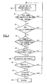
- La figure 3 est un organigramme illustrant la succession des différentes étapes d'analyse pour la mise en oeuvre de l'invention.
- FIG. 1 is a timing diagram showing, during three successive cardiac cycles, the variations of the endocavitary acceleration as well as the electrogram and the surface electrocardiogram.
- FIG. 2 is another chronogram showing, during six successive cardiac cycles, the various signals collected representative of successive depolarizations and the signals indicating the presence of an endocardial acceleration peak.
- FIG. 3 is a flowchart illustrating the succession of the different analysis steps for the implementation of the invention.
On va maintenant décrire un exemple de réalisation du dispositif de l'invention.An embodiment of the device of the invention will now be described.
En ce qui concerne ses aspects logiciels, l'invention peut être mise en oeuvre par une programmation appropriée du logiciel de commande d'un stimulateur connu, par exemple de type stimulateur cardiaque ou défibrillateur/cardioverteur, comprenant des moyens d'acquisition d'un signal fourni par des sondes endocavitaires et/ou un ou plusieurs capteurs implantés.With regard to its software aspects, the invention can be implemented by appropriate programming of the control software of a known pacemaker, for example of pacemaker or defibrillator / cardioverter type, comprising means for acquiring a signal provided by endocardial probes and / or one or more implanted sensors.
L'invention peut notamment être appliquée aux dispositifs implantables commercialisés par ELA Médical, Montrouge, France tels que les appareils Symphony et ELA Rhapsody. The invention can in particular be applied to implantable devices marketed by ELA Medical, Montrouge, France such as Symphony and ELA Rhapsody devices .
Il s'agit de dispositifs à microprocesseur programmables comportant des circuits pour recevoir, mettre en forme et traiter des signaux électriques recueillis par des électrodes implantées, et délivrer des impulsions de stimulation à ces électrodes. Il est possible d'y transmettre par télémétrie des logiciels qui seront conservés en mémoire et exécutés pour mettre en oeuvre les fonctions de l'invention qui seront décrites ci-dessous. L'adaptation de ces appareils à la mise en oeuvre des fonctions de l'invention est à la portée de l'homme du métier, et elle ne sera pas décrite en détail.These are programmable microprocessor devices having circuitry for receiving, shaping, and processing electrical signals collected by implanted electrodes, and delivering pacing pulses to these electrodes. It is possible to transmit there by telemetry software which will be stored in memory and executed to implement the functions of the invention which will be described below. The adaptation of these devices to the implementation of the functions of the invention is within the abilities of those skilled in the art, and it will not be described in detail.
Sur la figure 1, on a représenté (tracé du haut), les variations de l'accélération endocardiaque (EA), mesurée par un capteur tel que celui décrit dans le
La présente invention propose d'utiliser les paramètres liés à l'accélération endocardiaque ainsi recueillis, notamment la survenue du pic PEA I (indiquée par la position temporelle de ce pic), pour confirmer ou infirmer la présence d'une activité mécanique du coeur.The present invention proposes to use the parameters related to the endocardial acceleration thus collected, in particular the occurrence of the peak PEA I (indicated by the temporal position of this peak), to confirm or deny the presence of a mechanical activity of the heart.
La première ligne de la figure 2 illustre la succession des évènements auriculaires P et ventriculaires R au cours de six cycles cardiaques successifs, pour un patient présentant un rythme sinusal normal.The first line of Figure 2 illustrates the succession of P and ventricular atrial events R over six successive cardiac cycles, for a patient with normal sinus rhythm.
Le recueil de ces signaux peut être perturbé par des potentiels électrochimiques apparaissant à l'endroit d'une fracture ou amorce de fracture de la sonde, potentiels qui peuvent se traduire par des perturbations, telles que celles illustrées en X et Y, susceptibles d'être interprétés à tort par le dispositif comme des évènements ventriculaires, conduisant à une suspicion erronée d'augmentation brutale du rythme ventriculaire, similaire à ce qui pourrait apparaître en cas de fibrillation ventriculaire.The collection of these signals can be disturbed by electrochemical potentials appearing at the location of a fracture or primer of fracture of the probe, potentials which can result in disturbances, such as than those illustrated in X and Y, which can be misinterpreted by the device as ventricular events, leading to an erroneous suspicion of a sudden increase in ventricular rate, similar to what might appear in case of ventricular fibrillation.
En revanche, la séquence des pics d'accélération (seconde ligne de la figure 2) n'est pas perturbée par une possible fracture ou amorce de fracture, puisqu'il s'agit de la détection d'une activité purement mécanique, comme on l'a expliqué plus haut. Le caractère régulier des contractions permet d'écarter le diagnostic de fibrillation ventriculaire et de suspecter la présence d'une fracture sur la sonde.On the other hand, the sequence of the acceleration peaks (second line of FIG. 2) is not disturbed by a possible fracture or fracture primer, since it is the detection of a purely mechanical activity, as one explained it above. The regularity of the contractions makes it possible to rule out the diagnosis of ventricular fibrillation and to suspect the presence of a fracture on the probe.
On va maintenant décrire plus en détail, en référence à l'organigramme de la figure 3, la manière dont est opérée la corrélation entre les signaux représentatifs des dépolarisations (première ligne de la figure 2) et ceux représentatifs des pics d'accélération (seconde ligne de la figure 2). Pour ce faire, la sonde endocavitaire portant le capteur d'accélération endocardiaque est différente de la sonde recueillant les signaux EGM.The manner in which the correlation between the signals representative of the depolarizations (first line of FIG. 2) and those representative of the acceleration peaks (second, will be described in greater detail with reference to the flowchart of FIG. line of Figure 2). To do this, the endocavity probe carrying the endocardial acceleration sensor is different from the probe collecting the EGM signals.
La première étape, référencée 10, consiste à recueillir de façon continue les signaux d'accélération endocardiaque et les dépolarisations ventriculaires, l'analyse étant opérée sur chaque cycle cardiaque.The first step, referenced 10, consists in continuously collecting endocardial acceleration signals and ventricular depolarizations, the analysis being performed on each cardiac cycle.
Le dispositif détermine à partir de ces mesures une première série de signaux représentatifs des dépolarisations ventriculaires, et une deuxième série de signaux représentatifs des pics d'accélération (avantageusement le pic PEA I).The device determines from these measurements a first series of signals representative of the ventricular depolarizations, and a second series of signals representative of the acceleration peaks (advantageously the peak PEA I).
Le dispositif peut notamment utiliser les signaux d'accélération endocardiaque au niveau du ventricule droit. Mais l'invention peut être également mise en oeuvre en utilisant des signaux représentatifs de l'accélération endocardiaque relevée au niveau :
- d'une oreillette,
- ou du ventricule gauche,
- ou d'un vaisseau sanguin périphérique du coeur, c'est-à-dire d'un vaisseau situé sur le coeur ou à proximité immédiate du coeur (en contact avec la paroi du coeur).
- an atrium,
- or left ventricle,
- or a peripheral blood vessel of the heart, i.e., a vessel located on the heart or in the immediate vicinity of the heart (in contact with the wall of the heart).
La première phase de l'analyse (étape 12) consiste à déterminer si les signaux de pics PEA sont stables en amplitude et/ou en intervalles de couplage (l'intervalle de couplage étant la période temporelle séparant deux pics relatifs à des cycles consécutifs). La condition de stabilité en amplitude signifie par exemple que l'amplitude du pic PEA I ne varie pas de plus de x % par rapport à la moyenne des y cycles précédents. La condition de stabilité du couplage signifie que l'intervalle de couplage ne varie pas de plus ou moins z millisecondes, par exemple plus ou moins 30 millisecondes d'un cycle au suivant.The first phase of the analysis (step 12) consists in determining whether the PEA peak signals are stable in amplitude and / or in coupling intervals (the coupling interval being the time period separating two peaks relating to consecutive cycles). The amplitude stability condition means, for example, that the amplitude of the PEA peak I does not vary by more than x% from the average of the previous cycles. The stability condition of the coupling means that the coupling interval does not vary by plus or minus z milliseconds, for example plus or minus 30 milliseconds from one cycle to the next.
En présence d'un rythme PEA stable révélateur de contractions régulières, le dispositif détermine (étape 14) si la fréquence de ces contractions (fréquence des pics PEA) est inférieure à une fréquence limite, inférieure à la zone de détection des tachycardies.In the presence of a steady PEA rhythm indicative of regular contractions, the device determines (step 14) whether the frequency of these contractions (frequency of the PEA peaks) is less than a limit frequency, lower than the zone of detection of tachycardias.
Dans la négative, il s'agit vraisemblablement d'une tachycardie avérée, pour laquelle un thérapie doit être envisagée sans qu'il y ait lieu de poursuivre l'analyse.If not, it is likely to be known tachycardia, for which therapy should be considered without further analysis.
Dans l'affirmative, donc en présence d'un rythme des contractions suffisamment lent, le dispositif examine (étape 16) s'il est en présence d'une série d'évènements ventriculaires de couplage court et variable (le critère de "couplage court" signifiant que les intervalles de couplage entre événements ventriculaires successifs sont inférieurs à un seuil donné, et le critère de "couplage variable" signifiant que les différences entre les intervalles de couplage dépassent un seuil donné sur un nombre prédéterminé de cycles successifs).If so, then in the presence of a slow pace of contractions, the device examines (step 16) whether there is a series of short and variable coupling ventricular events (the "short coupling" criterion). "meaning that the coupling intervals between successive ventricular events are less than a given threshold, and the" variable coupling "criterion means that the differences between the coupling intervals exceed a given threshold over a predetermined number of successive cycles).
Si l'analyse des dépolarisations ventriculaires révèle à l'étape 16 un rythme rapide et instable, le dispositif détermine si les amplitudes de ces dépolarisations sont inférieures ou non à un seuil donné (étape 18). Dans l'affirmative, il est probable que ces signaux ne représentent pas de véritables dépolarisations, et le diagnostic de fracture n'est pas poursuivi. Il est également possible, à cette étape, d'effectuer le test sur une pluralité d'évènements ventriculaires, le test consistant à déterminer le nombre d'évènements ventriculaires présentant une amplitude inférieure au seuil prédéterminé, et à n'abandonner la poursuite du diagnostic que si le nombre de ces évènements est supérieur à un nombre donné, ceci afin d'éviter que le diagnostic ne soit interrompu par un nombre réduit d'évènements atypiques.If the analysis of the ventricular depolarizations reveals in step 16 a fast and unstable rhythm, the device determines whether the amplitudes of these depolarizations are lower than a given threshold (step 18). If so, it is likely that these signals do not represent true depolarizations, and the diagnosis of fracture is not continued. It is also possible, at this stage, to perform the test on a plurality of ventricular events, the test consisting of determining the number of ventricular events having an amplitude less than the predetermined threshold, and to abandon the continuation of the diagnosis. if the number of these events is greater than a given number, this in order to avoid that the diagnosis is interrupted by a reduced number of atypical events.
Si les conditions établies aux étapes 12 à 18 sont vérifiées, alors le dispositif détermine qu'il y a suspicion de fracture (étape 20), par exemple en positionnant un indicateur spécifique.If the conditions set in
Cette suspicion de fracture peut être en particulier utilisée pour déclencher une mesure d'impédance de la sonde (étape 22) par un procédé connu, par exemple du type exposé dans le
Si cette mesure d'impédance révèle effectivement un défaut (étape 22), et que, en tout état de cause, le diagnostic de suspicion de fracture est un diagnostic récurrent (étape 24), alors le dispositif considère qu'il y a une fracture avérée et produit un signal d'alarme (étape 26).If this impedance measurement actually reveals a defect (step 22), and in any event, the diagnosis of suspected fracture is a recurrent diagnosis (step 24), then the device considers that there is a fracture proved and produces an alarm signal (step 26).
L'étape 24 consistant à vérifier si la suspicion est récurrente ou non permet d'éliminer le cas de certains signaux parasites survenant de manière ponctuelle en produisant des artefacts de détection qui ne sont pas liés à une fracture de sonde. En effet, une fracture apparaît généralement de manière progressive et, tout au moins au début, de manière intermittente. C'est la répétition des perturbations produites par les courants de rupture qui va permettre de confirmer qu'il s'agit bien d'une fracture de sonde, et non d'artefacts de bruit extrinsèque, tels que les interférences électromagnétiques provenant d'équipements électroniques de surveillance, d'appareils électriques environnants, d'instruments électrochirurgicaux de systèmes de communication, etc.The
L'alarme produite à l'étape 26 peut comprendre notamment :
- l'enregistrement d'un marqueur dans une mémoire du dispositif, permettant de signaler à l'électrophysiologiste lors d'une visite de routine ultérieure qu'un phénomène de fracture a été diagnostiqué par l'appareil, et/ou
- la production par un "buzzer" d'un signal sonore à destination du patient, de manière à alerter celui-ci sans délai, et/ou
- l'émission d'un signal par des moyens de transmission RF.
- recording a marker in a memory of the device, making it possible to signal to the electrophysiologist during a subsequent routine visit that a fracture phenomenon has been diagnosed by the device, and / or
- the production by a "buzzer" of an audible signal for the patient, so as to alert it without delay, and / or
- the emission of a signal by RF transmission means.
Claims (14)
dispositif caractérisé en ce qu'il comporte en outre des moyens de détection de fracture de ladite sonde, comprenant des moyens pour :
device characterized in that it further comprises means for detecting fracture of said probe, comprising means for:
Applications Claiming Priority (1)
| Application Number | Priority Date | Filing Date | Title |
|---|---|---|---|
| FR0604445A FR2901147A1 (en) | 2006-05-18 | 2006-05-18 | ACTIVE IMPLANTABLE MEDICAL DEVICE FOR CARDIAC STIMULATION, RESYNCHRONIZATION, CARDIOVERSION AND / OR DEFIBRILLATION, HAVING PROBE FRACTURE DETECTION MEANS |
Publications (2)
| Publication Number | Publication Date |
|---|---|
| EP1857143A1 true EP1857143A1 (en) | 2007-11-21 |
| EP1857143B1 EP1857143B1 (en) | 2008-03-26 |
Family
ID=37511590
Family Applications (1)
| Application Number | Title | Priority Date | Filing Date |
|---|---|---|---|
| EP07290606A Active EP1857143B1 (en) | 2006-05-18 | 2007-05-14 | Active implantable medical device for cardiac stimulation, resynchronisation, cardioversion and/or defibrillation, comprising means for detecting catheter fractures |
Country Status (4)
| Country | Link |
|---|---|
| US (1) | US7966068B2 (en) |
| EP (1) | EP1857143B1 (en) |
| DE (1) | DE602007000008T2 (en) |
| FR (1) | FR2901147A1 (en) |
Cited By (1)
| Publication number | Priority date | Publication date | Assignee | Title |
|---|---|---|---|---|
| WO2022069680A1 (en) * | 2020-10-01 | 2022-04-07 | Sorin Crm Sas | Device for monitoring operation of a probe of an implantable active cardiac device |
Families Citing this family (5)
| Publication number | Priority date | Publication date | Assignee | Title |
|---|---|---|---|---|
| US10118042B2 (en) * | 2008-10-31 | 2018-11-06 | Medtronic, Inc. | Lead integrity testing triggered by sensed asystole |
| US8374692B2 (en) | 2010-06-30 | 2013-02-12 | Medtronic, Inc. | Identifying a lead related condition based on motion-based lead impedance fluctuations |
| US20120123496A1 (en) * | 2010-11-12 | 2012-05-17 | Medtronic, Inc. | Connectivity detection and type identification of an implanted lead for an implantable medical device |
| US9327131B2 (en) | 2010-12-06 | 2016-05-03 | Pacesetter, Inc. | Detecting implanted medical electrical lead dislodgement using cardiac signals |
| US8965506B2 (en) * | 2011-12-22 | 2015-02-24 | Medtronic, Inc. | Fault tolerant pacing |
Citations (8)
| Publication number | Priority date | Publication date | Assignee | Title |
|---|---|---|---|---|
| EP0655260A2 (en) * | 1993-10-05 | 1995-05-31 | SORIN BIOMEDICA CARDIO S.p.A. | Device for determining myocardial function and corresponding procedure |
| US5755742A (en) * | 1996-11-05 | 1998-05-26 | Medtronic, Inc. | Cardioversion/defibrillation lead impedance measurement system |
| US5776168A (en) * | 1996-04-03 | 1998-07-07 | Medtronic, Inc. | EGM recording system for implantable medical device |
| US5814088A (en) * | 1997-03-26 | 1998-09-29 | Sulzer Intermedics Inc. | Cardiac stimulator with lead failure detector and warning system |
| EP1433496A1 (en) * | 2002-12-24 | 2004-06-30 | Ela Medical | Active medical device, in particular implantable device such as pacemaker, defibrillator, cardioverter or multisite device, having means for detecting sleep disorders |
| EP1438985A1 (en) * | 2003-01-17 | 2004-07-21 | Ela Medical | Implantable medical device e.g. a pacemaker with means for determining the presence and the type of the associated probe |
| US6892092B2 (en) * | 2001-10-29 | 2005-05-10 | Cardiac Pacemakers, Inc. | Cardiac rhythm management system with noise detector utilizing a hysteresis providing threshold |
| EP1537894A1 (en) * | 2003-12-03 | 2005-06-08 | Ela Medical | Implantable medical device with Holter's recording functions |
Family Cites Families (3)
| Publication number | Priority date | Publication date | Assignee | Title |
|---|---|---|---|---|
| IT1245814B (en) | 1991-05-21 | 1994-10-18 | Sorin Biomedica Spa | RATE RESPONSIVE CARDIOSTIMULATOR DEVICE |
| US6351675B1 (en) * | 1999-10-04 | 2002-02-26 | Medtronic, Inc. | System and method of programming an implantable medical device |
| FR2818554B1 (en) | 2000-12-22 | 2003-03-28 | Ela Medical Sa | METHOD FOR MEASURING THE COMPLEX IMPEDANCE OF A PROBE OF AN ACTIVE IMPLANTABLE MEDICAL DEVICE, IN PARTICULAR A HEART STIMULATOR, DEFIBRILLATOR AND / OR CARDIOVERTER |
-
2006
- 2006-05-18 FR FR0604445A patent/FR2901147A1/en active Pending
-
2007
- 2007-05-14 EP EP07290606A patent/EP1857143B1/en active Active
- 2007-05-14 DE DE602007000008T patent/DE602007000008T2/en active Active
- 2007-05-18 US US11/750,519 patent/US7966068B2/en active Active
Patent Citations (8)
| Publication number | Priority date | Publication date | Assignee | Title |
|---|---|---|---|---|
| EP0655260A2 (en) * | 1993-10-05 | 1995-05-31 | SORIN BIOMEDICA CARDIO S.p.A. | Device for determining myocardial function and corresponding procedure |
| US5776168A (en) * | 1996-04-03 | 1998-07-07 | Medtronic, Inc. | EGM recording system for implantable medical device |
| US5755742A (en) * | 1996-11-05 | 1998-05-26 | Medtronic, Inc. | Cardioversion/defibrillation lead impedance measurement system |
| US5814088A (en) * | 1997-03-26 | 1998-09-29 | Sulzer Intermedics Inc. | Cardiac stimulator with lead failure detector and warning system |
| US6892092B2 (en) * | 2001-10-29 | 2005-05-10 | Cardiac Pacemakers, Inc. | Cardiac rhythm management system with noise detector utilizing a hysteresis providing threshold |
| EP1433496A1 (en) * | 2002-12-24 | 2004-06-30 | Ela Medical | Active medical device, in particular implantable device such as pacemaker, defibrillator, cardioverter or multisite device, having means for detecting sleep disorders |
| EP1438985A1 (en) * | 2003-01-17 | 2004-07-21 | Ela Medical | Implantable medical device e.g. a pacemaker with means for determining the presence and the type of the associated probe |
| EP1537894A1 (en) * | 2003-12-03 | 2005-06-08 | Ela Medical | Implantable medical device with Holter's recording functions |
Cited By (1)
| Publication number | Priority date | Publication date | Assignee | Title |
|---|---|---|---|---|
| WO2022069680A1 (en) * | 2020-10-01 | 2022-04-07 | Sorin Crm Sas | Device for monitoring operation of a probe of an implantable active cardiac device |
Also Published As
| Publication number | Publication date |
|---|---|
| DE602007000008D1 (en) | 2008-05-08 |
| EP1857143B1 (en) | 2008-03-26 |
| FR2901147A1 (en) | 2007-11-23 |
| US7966068B2 (en) | 2011-06-21 |
| DE602007000008T2 (en) | 2009-06-18 |
| US20070270914A1 (en) | 2007-11-22 |
Similar Documents
| Publication | Publication Date | Title |
|---|---|---|
| EP1857142B1 (en) | Active implantable medical device for cardiac stimulation, resynchronisation, cardioversion and/or defibrillation, comprising means for detecting ventricular noise artefacts | |
| US6810283B2 (en) | Multiple templates for filtering of far field R-waves | |
| US8750976B2 (en) | Implanted multichamber cardiac device with selective use of reliable atrial information | |
| US8874210B2 (en) | Apparatus and method for analyzing patient tolerance to a stimulation mode favoring a spontaneous atrioventricular conduction | |
| EP2189182B1 (en) | Implantable active medical device comprising means for atrial capture testing | |
| EP2412401B1 (en) | Active implantable medical device with means for testing ventricular capture by analysing an endocardiac acceleration signal | |
| EP2324885B1 (en) | Active medical device including means for capture testing through cardiac vectogram analysis | |
| EP1857143B1 (en) | Active implantable medical device for cardiac stimulation, resynchronisation, cardioversion and/or defibrillation, comprising means for detecting catheter fractures | |
| US20100305640A1 (en) | Method, device, implantable stimulator and dual chamber cardiac therapy system | |
| EP1308183B1 (en) | Active implantable medical device for treating heart rhythm disorders, having improved means for detecting atrial arrhythmias | |
| EP1731195B1 (en) | Active implantable medical device with AAI/DDD mode switching, in particular pacemaker, with improved control of mode switching in the presence of uncertain ventricular events | |
| US5601614A (en) | Method and device for determining whether electrical signals in a heart are caused by an atrial depolarization | |
| EP2803385B1 (en) | Implantable heart re-timer with biventricular stimulation and detection of losses of capture and anode stimulations | |
| EP2596832B1 (en) | Implantable cardioverter-defibrillator medical device with dynamically adjustable ventricular sensing threshold | |
| EP3402397A1 (en) | Active implantable medical defibrillation device, including improved means for discriminating between external noise and probe breakage and for characterising tachyarrhythmias | |
| EP2196238B1 (en) | Active implantable medical cardiac device, including means of antitachycardiac auricular stimulation and antibradycardiac ventricular stimulation | |
| EP4329614A1 (en) | Process for assigning an item of identification information to a signal from a cardiac electrode | |
| WO2009064222A1 (en) | Tachycardia classification | |
| US6721592B2 (en) | Automatic electrogram measurement | |
| FR3122078A1 (en) | Method for assigning identification information to a signal from a cardiac electrode |
Legal Events
| Date | Code | Title | Description |
|---|---|---|---|
| PUAI | Public reference made under article 153(3) epc to a published international application that has entered the european phase |
Free format text: ORIGINAL CODE: 0009012 |
|
| GRAP | Despatch of communication of intention to grant a patent |
Free format text: ORIGINAL CODE: EPIDOSNIGR1 |
|
| 17P | Request for examination filed |
Effective date: 20070608 |
|
| AK | Designated contracting states |
Kind code of ref document: A1 Designated state(s): AT BE BG CH CY CZ DE DK EE ES FI FR GB GR HU IE IS IT LI LT LU LV MC MT NL PL PT RO SE SI SK TR |
|
| AX | Request for extension of the european patent |
Extension state: AL BA HR MK YU |
|
| GRAS | Grant fee paid |
Free format text: ORIGINAL CODE: EPIDOSNIGR3 |
|
| GRAA | (expected) grant |
Free format text: ORIGINAL CODE: 0009210 |
|
| RIN1 | Information on inventor provided before grant (corrected) |
Inventor name: AMBLARD, AMEL Inventor name: VINCENT, ELODIE |
|
| AK | Designated contracting states |
Kind code of ref document: B1 Designated state(s): AT BE BG CH CY CZ DE DK EE ES FI FR GB GR HU IE IS IT LI LT LU LV MC MT NL PL PT RO SE SI SK TR |
|
| REG | Reference to a national code |
Ref country code: GB Ref legal event code: FG4D Free format text: NOT ENGLISH |
|
| REG | Reference to a national code |
Ref country code: CH Ref legal event code: EP Ref country code: IE Ref legal event code: FG4D Free format text: LANGUAGE OF EP DOCUMENT: FRENCH |
|
| REF | Corresponds to: |
Ref document number: 602007000008 Country of ref document: DE Date of ref document: 20080508 Kind code of ref document: P |
|
| REG | Reference to a national code |
Ref country code: SE Ref legal event code: TRGR |
|
| AKX | Designation fees paid |
Designated state(s): AT BE BG CH CY CZ DE DK EE ES FI FR GB GR HU IE IS IT LI LT LU LV MC MT NL PL PT RO SE SI SK TR |
|
| PG25 | Lapsed in a contracting state [announced via postgrant information from national office to epo] |
Ref country code: FI Free format text: LAPSE BECAUSE OF FAILURE TO SUBMIT A TRANSLATION OF THE DESCRIPTION OR TO PAY THE FEE WITHIN THE PRESCRIBED TIME-LIMIT Effective date: 20080326 |
|
| PG25 | Lapsed in a contracting state [announced via postgrant information from national office to epo] |
Ref country code: LV Free format text: LAPSE BECAUSE OF FAILURE TO SUBMIT A TRANSLATION OF THE DESCRIPTION OR TO PAY THE FEE WITHIN THE PRESCRIBED TIME-LIMIT Effective date: 20080326 Ref country code: SI Free format text: LAPSE BECAUSE OF FAILURE TO SUBMIT A TRANSLATION OF THE DESCRIPTION OR TO PAY THE FEE WITHIN THE PRESCRIBED TIME-LIMIT Effective date: 20080326 Ref country code: PL Free format text: LAPSE BECAUSE OF FAILURE TO SUBMIT A TRANSLATION OF THE DESCRIPTION OR TO PAY THE FEE WITHIN THE PRESCRIBED TIME-LIMIT Effective date: 20080326 |
|
| PG25 | Lapsed in a contracting state [announced via postgrant information from national office to epo] |
Ref country code: ES Free format text: LAPSE BECAUSE OF FAILURE TO SUBMIT A TRANSLATION OF THE DESCRIPTION OR TO PAY THE FEE WITHIN THE PRESCRIBED TIME-LIMIT Effective date: 20080707 Ref country code: CZ Free format text: LAPSE BECAUSE OF FAILURE TO SUBMIT A TRANSLATION OF THE DESCRIPTION OR TO PAY THE FEE WITHIN THE PRESCRIBED TIME-LIMIT Effective date: 20080326 Ref country code: SK Free format text: LAPSE BECAUSE OF FAILURE TO SUBMIT A TRANSLATION OF THE DESCRIPTION OR TO PAY THE FEE WITHIN THE PRESCRIBED TIME-LIMIT Effective date: 20080326 Ref country code: PT Free format text: LAPSE BECAUSE OF FAILURE TO SUBMIT A TRANSLATION OF THE DESCRIPTION OR TO PAY THE FEE WITHIN THE PRESCRIBED TIME-LIMIT Effective date: 20080901 |
|
| PG25 | Lapsed in a contracting state [announced via postgrant information from national office to epo] |
Ref country code: RO Free format text: LAPSE BECAUSE OF FAILURE TO SUBMIT A TRANSLATION OF THE DESCRIPTION OR TO PAY THE FEE WITHIN THE PRESCRIBED TIME-LIMIT Effective date: 20080326 |
|
| PG25 | Lapsed in a contracting state [announced via postgrant information from national office to epo] |
Ref country code: MC Free format text: LAPSE BECAUSE OF NON-PAYMENT OF DUE FEES Effective date: 20080531 Ref country code: IS Free format text: LAPSE BECAUSE OF FAILURE TO SUBMIT A TRANSLATION OF THE DESCRIPTION OR TO PAY THE FEE WITHIN THE PRESCRIBED TIME-LIMIT Effective date: 20080726 |
|
| PG25 | Lapsed in a contracting state [announced via postgrant information from national office to epo] |
Ref country code: EE Free format text: LAPSE BECAUSE OF FAILURE TO SUBMIT A TRANSLATION OF THE DESCRIPTION OR TO PAY THE FEE WITHIN THE PRESCRIBED TIME-LIMIT Effective date: 20080326 Ref country code: LT Free format text: LAPSE BECAUSE OF FAILURE TO SUBMIT A TRANSLATION OF THE DESCRIPTION OR TO PAY THE FEE WITHIN THE PRESCRIBED TIME-LIMIT Effective date: 20080326 Ref country code: NL Free format text: LAPSE BECAUSE OF FAILURE TO SUBMIT A TRANSLATION OF THE DESCRIPTION OR TO PAY THE FEE WITHIN THE PRESCRIBED TIME-LIMIT Effective date: 20080326 Ref country code: DK Free format text: LAPSE BECAUSE OF FAILURE TO SUBMIT A TRANSLATION OF THE DESCRIPTION OR TO PAY THE FEE WITHIN THE PRESCRIBED TIME-LIMIT Effective date: 20080326 |
|
| PLBE | No opposition filed within time limit |
Free format text: ORIGINAL CODE: 0009261 |
|
| STAA | Information on the status of an ep patent application or granted ep patent |
Free format text: STATUS: NO OPPOSITION FILED WITHIN TIME LIMIT |
|
| 26N | No opposition filed |
Effective date: 20081230 |
|
| PG25 | Lapsed in a contracting state [announced via postgrant information from national office to epo] |
Ref country code: BG Free format text: LAPSE BECAUSE OF FAILURE TO SUBMIT A TRANSLATION OF THE DESCRIPTION OR TO PAY THE FEE WITHIN THE PRESCRIBED TIME-LIMIT Effective date: 20080626 |
|
| PG25 | Lapsed in a contracting state [announced via postgrant information from national office to epo] |
Ref country code: CY Free format text: LAPSE BECAUSE OF FAILURE TO SUBMIT A TRANSLATION OF THE DESCRIPTION OR TO PAY THE FEE WITHIN THE PRESCRIBED TIME-LIMIT Effective date: 20080326 |
|
| BERE | Be: lapsed |
Owner name: ELA MEDICAL Effective date: 20090531 |
|
| PG25 | Lapsed in a contracting state [announced via postgrant information from national office to epo] |
Ref country code: BE Free format text: LAPSE BECAUSE OF NON-PAYMENT OF DUE FEES Effective date: 20090531 |
|
| PG25 | Lapsed in a contracting state [announced via postgrant information from national office to epo] |
Ref country code: HU Free format text: LAPSE BECAUSE OF FAILURE TO SUBMIT A TRANSLATION OF THE DESCRIPTION OR TO PAY THE FEE WITHIN THE PRESCRIBED TIME-LIMIT Effective date: 20080927 |
|
| PG25 | Lapsed in a contracting state [announced via postgrant information from national office to epo] |
Ref country code: TR Free format text: LAPSE BECAUSE OF FAILURE TO SUBMIT A TRANSLATION OF THE DESCRIPTION OR TO PAY THE FEE WITHIN THE PRESCRIBED TIME-LIMIT Effective date: 20080326 |
|
| PG25 | Lapsed in a contracting state [announced via postgrant information from national office to epo] |
Ref country code: GR Free format text: LAPSE BECAUSE OF FAILURE TO SUBMIT A TRANSLATION OF THE DESCRIPTION OR TO PAY THE FEE WITHIN THE PRESCRIBED TIME-LIMIT Effective date: 20080627 |
|
| PG25 | Lapsed in a contracting state [announced via postgrant information from national office to epo] |
Ref country code: LU Free format text: LAPSE BECAUSE OF NON-PAYMENT OF DUE FEES Effective date: 20080514 |
|
| REG | Reference to a national code |
Ref country code: CH Ref legal event code: PL |
|
| PG25 | Lapsed in a contracting state [announced via postgrant information from national office to epo] |
Ref country code: LI Free format text: LAPSE BECAUSE OF NON-PAYMENT OF DUE FEES Effective date: 20110531 Ref country code: CH Free format text: LAPSE BECAUSE OF NON-PAYMENT OF DUE FEES Effective date: 20110531 |
|
| PGFP | Annual fee paid to national office [announced via postgrant information from national office to epo] |
Ref country code: IE Payment date: 20120510 Year of fee payment: 6 |
|
| PGFP | Annual fee paid to national office [announced via postgrant information from national office to epo] |
Ref country code: SE Payment date: 20120511 Year of fee payment: 6 |
|
| REG | Reference to a national code |
Ref country code: SE Ref legal event code: EUG |
|
| PG25 | Lapsed in a contracting state [announced via postgrant information from national office to epo] |
Ref country code: SE Free format text: LAPSE BECAUSE OF NON-PAYMENT OF DUE FEES Effective date: 20130515 |
|
| REG | Reference to a national code |
Ref country code: IE Ref legal event code: MM4A |
|
| PG25 | Lapsed in a contracting state [announced via postgrant information from national office to epo] |
Ref country code: IE Free format text: LAPSE BECAUSE OF NON-PAYMENT OF DUE FEES Effective date: 20130514 |
|
| REG | Reference to a national code |
Ref country code: AT Ref legal event code: MK05 Ref document number: 676962 Country of ref document: AT Kind code of ref document: T Effective date: 20080326 |
|
| PG25 | Lapsed in a contracting state [announced via postgrant information from national office to epo] |
Ref country code: AT Free format text: LAPSE BECAUSE OF FAILURE TO SUBMIT A TRANSLATION OF THE DESCRIPTION OR TO PAY THE FEE WITHIN THE PRESCRIBED TIME-LIMIT Effective date: 20080326 |
|
| REG | Reference to a national code |
Ref country code: FR Ref legal event code: PLFP Year of fee payment: 10 |
|
| REG | Reference to a national code |
Ref country code: FR Ref legal event code: PLFP Year of fee payment: 11 |
|
| REG | Reference to a national code |
Ref country code: FR Ref legal event code: PLFP Year of fee payment: 12 |
|
| PGFP | Annual fee paid to national office [announced via postgrant information from national office to epo] |
Ref country code: IT Payment date: 20230517 Year of fee payment: 17 Ref country code: FR Payment date: 20230523 Year of fee payment: 17 Ref country code: DE Payment date: 20230510 Year of fee payment: 17 |
|
| P01 | Opt-out of the competence of the unified patent court (upc) registered |
Effective date: 20230714 |
|
| PGFP | Annual fee paid to national office [announced via postgrant information from national office to epo] |
Ref country code: GB Payment date: 20230519 Year of fee payment: 17 |