EP1829505A2 - Gastric band suture tab extender - Google Patents
Gastric band suture tab extender Download PDFInfo
- Publication number
- EP1829505A2 EP1829505A2 EP07250830A EP07250830A EP1829505A2 EP 1829505 A2 EP1829505 A2 EP 1829505A2 EP 07250830 A EP07250830 A EP 07250830A EP 07250830 A EP07250830 A EP 07250830A EP 1829505 A2 EP1829505 A2 EP 1829505A2
- Authority
- EP
- European Patent Office
- Prior art keywords
- gastric band
- extender
- latching
- suture tab
- shaped
- Prior art date
- Legal status (The legal status is an assumption and is not a legal conclusion. Google has not performed a legal analysis and makes no representation as to the accuracy of the status listed.)
- Granted
Links
- 230000002496 gastric effect Effects 0.000 title claims abstract description 218
- 239000004606 Fillers/Extenders Substances 0.000 title claims abstract description 208
- 230000007246 mechanism Effects 0.000 claims abstract description 35
- 230000008878 coupling Effects 0.000 claims abstract description 25
- 238000010168 coupling process Methods 0.000 claims abstract description 25
- 238000005859 coupling reaction Methods 0.000 claims abstract description 25
- 230000014759 maintenance of location Effects 0.000 claims description 18
- 210000002784 stomach Anatomy 0.000 description 37
- 239000000463 material Substances 0.000 description 15
- 238000000034 method Methods 0.000 description 13
- 230000003014 reinforcing effect Effects 0.000 description 13
- 238000005520 cutting process Methods 0.000 description 11
- 239000012530 fluid Substances 0.000 description 8
- 208000008589 Obesity Diseases 0.000 description 7
- 239000003292 glue Substances 0.000 description 6
- 239000003356 suture material Substances 0.000 description 6
- 210000001519 tissue Anatomy 0.000 description 6
- 238000004026 adhesive bonding Methods 0.000 description 5
- 208000012696 congenital leptin deficiency Diseases 0.000 description 5
- 238000010276 construction Methods 0.000 description 5
- 238000013461 design Methods 0.000 description 5
- 208000001022 morbid obesity Diseases 0.000 description 5
- 229920001296 polysiloxane Polymers 0.000 description 5
- 241001272720 Medialuna californiensis Species 0.000 description 3
- 239000000853 adhesive Substances 0.000 description 3
- 230000001070 adhesive effect Effects 0.000 description 3
- 230000008901 benefit Effects 0.000 description 3
- 230000008859 change Effects 0.000 description 3
- 230000009977 dual effect Effects 0.000 description 3
- 238000003780 insertion Methods 0.000 description 3
- 230000037431 insertion Effects 0.000 description 3
- 230000009467 reduction Effects 0.000 description 3
- 230000002829 reductive effect Effects 0.000 description 3
- 230000000007 visual effect Effects 0.000 description 3
- 238000012800 visualization Methods 0.000 description 3
- GWEVSGVZZGPLCZ-UHFFFAOYSA-N Titan oxide Chemical compound O=[Ti]=O GWEVSGVZZGPLCZ-UHFFFAOYSA-N 0.000 description 2
- TZCXTZWJZNENPQ-UHFFFAOYSA-L barium sulfate Chemical compound [Ba+2].[O-]S([O-])(=O)=O TZCXTZWJZNENPQ-UHFFFAOYSA-L 0.000 description 2
- 238000013037 co-molding Methods 0.000 description 2
- 230000003247 decreasing effect Effects 0.000 description 2
- 230000001747 exhibiting effect Effects 0.000 description 2
- 239000011521 glass Substances 0.000 description 2
- 238000004519 manufacturing process Methods 0.000 description 2
- 230000013011 mating Effects 0.000 description 2
- 239000000203 mixture Substances 0.000 description 2
- 238000000465 moulding Methods 0.000 description 2
- 235000020824 obesity Nutrition 0.000 description 2
- 229920000260 silastic Polymers 0.000 description 2
- 238000001356 surgical procedure Methods 0.000 description 2
- 238000011282 treatment Methods 0.000 description 2
- 206010007559 Cardiac failure congestive Diseases 0.000 description 1
- 208000034347 Faecal incontinence Diseases 0.000 description 1
- 206010019280 Heart failures Diseases 0.000 description 1
- 206010020710 Hyperphagia Diseases 0.000 description 1
- 206010020772 Hypertension Diseases 0.000 description 1
- FAPWRFPIFSIZLT-UHFFFAOYSA-M Sodium chloride Chemical compound [Na+].[Cl-] FAPWRFPIFSIZLT-UHFFFAOYSA-M 0.000 description 1
- 208000006011 Stroke Diseases 0.000 description 1
- 206010046543 Urinary incontinence Diseases 0.000 description 1
- 230000002411 adverse Effects 0.000 description 1
- 230000004075 alteration Effects 0.000 description 1
- 210000003484 anatomy Anatomy 0.000 description 1
- 238000007681 bariatric surgery Methods 0.000 description 1
- 239000003086 colorant Substances 0.000 description 1
- 230000006835 compression Effects 0.000 description 1
- 238000007906 compression Methods 0.000 description 1
- 208000029078 coronary artery disease Diseases 0.000 description 1
- 230000006378 damage Effects 0.000 description 1
- 206010012601 diabetes mellitus Diseases 0.000 description 1
- 230000001079 digestive effect Effects 0.000 description 1
- 238000002224 dissection Methods 0.000 description 1
- 210000001198 duodenum Anatomy 0.000 description 1
- 201000006549 dyspepsia Diseases 0.000 description 1
- 239000013536 elastomeric material Substances 0.000 description 1
- 230000002708 enhancing effect Effects 0.000 description 1
- 239000000945 filler Substances 0.000 description 1
- 230000037406 food intake Effects 0.000 description 1
- 235000012631 food intake Nutrition 0.000 description 1
- 235000019525 fullness Nutrition 0.000 description 1
- 208000021302 gastroesophageal reflux disease Diseases 0.000 description 1
- 210000001035 gastrointestinal tract Anatomy 0.000 description 1
- 208000024798 heartburn Diseases 0.000 description 1
- 239000007943 implant Substances 0.000 description 1
- 201000001881 impotence Diseases 0.000 description 1
- 238000009434 installation Methods 0.000 description 1
- 230000002427 irreversible effect Effects 0.000 description 1
- 230000007794 irritation Effects 0.000 description 1
- 210000001630 jejunum Anatomy 0.000 description 1
- 230000000670 limiting effect Effects 0.000 description 1
- 210000004185 liver Anatomy 0.000 description 1
- 239000002184 metal Substances 0.000 description 1
- 229910052751 metal Inorganic materials 0.000 description 1
- 150000002739 metals Chemical class 0.000 description 1
- 238000012986 modification Methods 0.000 description 1
- 230000004048 modification Effects 0.000 description 1
- UEPXBTCUIIGYCY-UHFFFAOYSA-N n-[3-[2-(2-hydroxyethoxy)-6-morpholin-4-ylpyridin-4-yl]-4-methylphenyl]-2-(trifluoromethyl)pyridine-4-carboxamide Chemical compound C1=C(C=2C=C(N=C(OCCO)C=2)N2CCOCC2)C(C)=CC=C1NC(=O)C1=CC=NC(C(F)(F)F)=C1 UEPXBTCUIIGYCY-UHFFFAOYSA-N 0.000 description 1
- 230000000399 orthopedic effect Effects 0.000 description 1
- 235000020830 overeating Nutrition 0.000 description 1
- 239000004033 plastic Substances 0.000 description 1
- 229920003023 plastic Polymers 0.000 description 1
- 230000002685 pulmonary effect Effects 0.000 description 1
- 235000019627 satiety Nutrition 0.000 description 1
- 230000036186 satiety Effects 0.000 description 1
- 239000011780 sodium chloride Substances 0.000 description 1
- 210000000952 spleen Anatomy 0.000 description 1
- 230000000472 traumatic effect Effects 0.000 description 1
- 230000004580 weight loss Effects 0.000 description 1
- 238000003466 welding Methods 0.000 description 1
Images


Classifications
-
- A—HUMAN NECESSITIES
- A61—MEDICAL OR VETERINARY SCIENCE; HYGIENE
- A61F—FILTERS IMPLANTABLE INTO BLOOD VESSELS; PROSTHESES; DEVICES PROVIDING PATENCY TO, OR PREVENTING COLLAPSING OF, TUBULAR STRUCTURES OF THE BODY, e.g. STENTS; ORTHOPAEDIC, NURSING OR CONTRACEPTIVE DEVICES; FOMENTATION; TREATMENT OR PROTECTION OF EYES OR EARS; BANDAGES, DRESSINGS OR ABSORBENT PADS; FIRST-AID KITS
- A61F5/00—Orthopaedic methods or devices for non-surgical treatment of bones or joints; Nursing devices; Anti-rape devices
- A61F5/0003—Apparatus for the treatment of obesity; Anti-eating devices
- A61F5/0013—Implantable devices or invasive measures
- A61F5/005—Gastric bands
- A61F5/0066—Closing devices for gastric bands
-
- A—HUMAN NECESSITIES
- A61—MEDICAL OR VETERINARY SCIENCE; HYGIENE
- A61F—FILTERS IMPLANTABLE INTO BLOOD VESSELS; PROSTHESES; DEVICES PROVIDING PATENCY TO, OR PREVENTING COLLAPSING OF, TUBULAR STRUCTURES OF THE BODY, e.g. STENTS; ORTHOPAEDIC, NURSING OR CONTRACEPTIVE DEVICES; FOMENTATION; TREATMENT OR PROTECTION OF EYES OR EARS; BANDAGES, DRESSINGS OR ABSORBENT PADS; FIRST-AID KITS
- A61F5/00—Orthopaedic methods or devices for non-surgical treatment of bones or joints; Nursing devices; Anti-rape devices
- A61F5/0003—Apparatus for the treatment of obesity; Anti-eating devices
- A61F5/0013—Implantable devices or invasive measures
- A61F5/005—Gastric bands
- A61F5/0053—Gastric bands remotely adjustable
-
- A—HUMAN NECESSITIES
- A61—MEDICAL OR VETERINARY SCIENCE; HYGIENE
- A61B—DIAGNOSIS; SURGERY; IDENTIFICATION
- A61B17/00—Surgical instruments, devices or methods, e.g. tourniquets
- A61B17/12—Surgical instruments, devices or methods, e.g. tourniquets for ligaturing or otherwise compressing tubular parts of the body, e.g. blood vessels, umbilical cord
- A61B17/132—Tourniquets
- A61B17/1322—Tourniquets comprising a flexible encircling member
- A61B17/1327—Tensioning clamps
-
- A—HUMAN NECESSITIES
- A61—MEDICAL OR VETERINARY SCIENCE; HYGIENE
- A61B—DIAGNOSIS; SURGERY; IDENTIFICATION
- A61B17/00—Surgical instruments, devices or methods, e.g. tourniquets
- A61B2017/0042—Surgical instruments, devices or methods, e.g. tourniquets with special provisions for gripping
Landscapes
- Health & Medical Sciences (AREA)
- Child & Adolescent Psychology (AREA)
- Obesity (AREA)
- Nursing (AREA)
- Orthopedic Medicine & Surgery (AREA)
- Engineering & Computer Science (AREA)
- Biomedical Technology (AREA)
- Heart & Thoracic Surgery (AREA)
- Vascular Medicine (AREA)
- Life Sciences & Earth Sciences (AREA)
- Animal Behavior & Ethology (AREA)
- General Health & Medical Sciences (AREA)
- Public Health (AREA)
- Veterinary Medicine (AREA)
- Surgical Instruments (AREA)
- Medicinal Preparation (AREA)
Abstract
Description
- This application is a continuation in part of
U.S. Patent Application Serial No. 11/182,072 U.S. Provisional Application Serial No. 60/699,369 - The invention relates to a gastric band and related accessories.
- Morbid obesity is a serious medical condition. In fact, morbid obesity has become highly pervasive in the United States, as well as other countries, and the trend appears to be heading in a negative direction. Complications associated with morbid obesity include hypertension, diabetes, coronary artery disease, stroke, congestive heart failure, multiple orthopedic problems and pulmonary insufficiency with markedly decreased life expectancy. With this in mind, and as those skilled in the art will certainly appreciate, the monetary and physical costs associated with morbid obesity are substantial. In fact, it is estimated the costs relating to obesity are in excess of one hundred billion dollars in the United States alone.
- A variety of surgical procedures have been developed to treat obesity. The most common currently performed procedure is Roux-en-Y gastric bypass (RYGB). This procedure is highly complex and is commonly utilized to treat people exhibiting morbid obesity. Other forms of bariatric surgery include Fobi pouch, bilio-pancreatic diversion, and gastroplastic or "stomach stapling". In addition, implantable devices are known which limit the passage of food through the stomach and affect satiety.
- In view of the highly invasive nature of many of these procedures, efforts have been made to develop less traumatic and less invasive procedures. Gastric-banding is one of these methods. Gastric-banding is a type of gastric reduction surgery attempting to limit food intake by reducing the size of the stomach. In contrast to RYGB and other stomach reduction procedures, gastric-banding does not require the alteration of the anatomy of the digestive tract in the duodenum or jejunum.
- Since the early 1980's, gastric bands have provided an effective alternative to gastric bypass and other irreversible surgical weight loss treatments for the morbidly obese. Several alternate procedures are performed under the heading of gastric-banding. Some banding techniques employ a gastric ring, others use a band, some use stomach staples and still other procedures use a combination of rings, bands and staples. Among the procedures most commonly performed are vertical banded gastroplasty (VBG), silastic ring gastroplasty (SRG) and adjustable silastic gastric banding (AGB).
- In general, the gastric band is wrapped around an upper portion of the patient's stomach, forming a stoma that is less than the normal interior diameter of the stomach. This restricts food passing from an upper portion to a lower digestive portion of the stomach. When the stoma is of an appropriate size, food held in the upper portion of the stomach provides a feeling of fullness that discourages over eating.
- More particularly, and in practice, the gastric band is inserted behind the stomach and the ends of the gastric band are coupled to latch the device about the stomach. However, it is often difficult to maneuver the ends of the gastric band for proper latching. As such, mechanisms for enhancing the application of gastric bands about a stomach are needed. The present invention provides such a mechanism in the form of an extension device for utilization in conjunction with currently available gastric bands, which is removable after the gastric band is properly installed. The present invention also provides an improved gastric band construction facilitating ease of application about a stomach and enhanced functionality once applied.
- It is, therefore, an object of the present invention to provide a removable suture tab extender for a gastric band. The extender is shaped and dimensioned for selective attachment to a first end of the gastric band, the gastric band including a latching mechanism composed of a first latching member positioned at the first end of the gastric band and a second latching member positioned at a second end of the gastric band. The gastric band extender includes an elongated body member having a first end and a second end. The first end of the elongated body member is shaped and dimensioned for coupling with the first latching member. The second end of the elongated body member includes a gripping section shaped and dimensioned to facilitate gripping thereof as the gastric band extender is passed through the second latching member.
- It is also an object of the present invention to provide a gastric band and suture tab extender. It includes a gastric band body having a latching mechanism composed of a first latching member positioned at a first end of the gastric band body and a second latching member positioned at a second end of the gastric band body. A suture tab extender as described above is releasable secured to the first end of the gastric band body.
- Other objects and advantages of the present invention will become apparent from the following detailed description when viewed in conjunction with the accompanying drawings, which set forth certain embodiments of the invention.
- The following numbered embodiments are a non-exhaustive list of subject-matter that is or may be claimed in this application or any divisional applications derived from it.
- Embodiment 1. A removable suture tab extender for a gastric band, the extender shaped and dimensioned for selective attachment to a first end of the gastric band, the gastric band including a latching mechanism composed of a first latching member positioned at the first end of the gastric band and a second latching member positioned at a second end of the gastric band, the gastric band extender comprising:
- an elongated body member including a first end and a second end;
- the first end of the elongated body member is shaped and dimensioned for coupling with the first latching member; and
- the second end of the elongated body member includes a gripping section shaped and dimensioned to facilitate gripping thereof as the gastric band extender is passed through the second latching member.
- Embodiment 2. The removable suture tab extender according to embodiment 1, further including a laterally extending retention member positioned between the first end and the second end of the extender.
- Embodiment 3. The removable suture tab extender according to embodiment 2, wherein the retention member includes a triangle shaped engagement surface.
- Embodiment 4. The removable suture tab extender according to embodiment 3, wherein the engagement surface tapers to widen as it extends toward the first end of the body member in a manner creating a surface over which the second latching member may slide during latching for interim attachment of the gastric band extender to the second latching member.
-
Embodiment 5. The removable suture tab extender according to embodiment 2, wherein the retention member includes a semi-circular shaped engagement surface. - Embodiment 6. The removable suture tab extender according to
embodiment 5, wherein the engagement surface tapers to widen as it extends toward the first end of the body member in a manner creating a surface over which the second latching member may slide during latching for interim attachment of the gastric band extender to the second latching member. - Embodiment 7. The removable suture tab extender according to embodiment 1, wherein the shaped and dimensioned first end of the elongated body member is a recess which mates with the first end of the gastric band.
- Embodiment 8. The removable suture tab extender according to embodiment 1, wherein the shaped and dimensioned first end of the elongated body member is an open recess which mates with the first end of the gastric band.
- Embodiment 9. The removable suture tab extender according to embodiment 1, wherein the first latching member includes a tab, and the recess is shaped and dimensioned for receiving the tab. - this recess allows the band and removable suture tab extender to move as a single functional unit.
-
Embodiment 10. The removable suture tab extender according to embodiment 1, wherein the first end of the body member is further provided with a tether strap. - Embodiment 11. The removable suture tab extender according to
embodiment 10, wherein the tether strap includes a bump shaped and dimensioned to engage the first end of the elongated body member for spacing the tether strap from the gastric band. -
Embodiment 12. The removable suture tab extender according toembodiment 10, wherein the first end of the elongated body member is provided with a bump for spacing the tether strap from the gastric band. - Embodiment 13. The removable suture tab extender according to
embodiment 10, wherein the tether includes a reinforcing member. -
Embodiment 14. The removable suture tab extender according toembodiment 10, wherein the tether strap includes a notched section. - Embodiment 15. The removable suture tab extender according to
embodiment 14, wherein a reinforcing member passes through the tether strap and the notched section exposes the reinforcing member. -
Embodiment 16. The removable suture tab extender according to embodiment 15, wherein the reinforcing member is a suture. - Embodiment 17. The removable suture tab extender according to
embodiment 10, wherein a suture loop extends from the second end of the elongated body member and suture material from the suture loop extends through the tether strap. -
Embodiment 18. The removable suture tab extender according to embodiment 17, wherein the tether strap includes a notched section and the notched section exposes the suture. - Embodiment 19. The removable suture tab extender according to
embodiment 10, wherein a suture secures the tether as it wraps about the gastric band. -
Embodiment 20. The removable suture tab extender according toembodiment 10, wherein a suture loop extends from the second end of the elongated body member and suture material from the suture loop extends from the first end of the elongated body member and is the tether strap. - Embodiment 21. The removable suture tab extender according to
embodiment 10, wherein the tether strap is shaped and dimensioned for passage through an aperture formed in the first latching member. -
Embodiment 22. The removable suture tab extender according to embodiment 21, wherein the first end of the body member includes a coupling indent formed in an outer surface of the first end of the body member for coupling with the tether strap after it is passed through the aperture formed in the first latching member. - Embodiment 23. The removable suture tab extender according to
embodiment 10, wherein the first end of the body member includes a coupling indent formed in the outer surface of the first end of the body member for coupling with the tether strap. -
Embodiment 24. The removable suture tab extender according to embodiment 1, wherein a suture loop extending from the first end thereof. - Embodiment 25. The removable suture tab extender according to embodiment 1, further including a gap shaped and dimensioned for passage of scissors therethrough for removal of the suture tab extender.
-
Embodiment 26. The removable suture tab extender according to embodiment 1, further including color coding for identification. - Embodiment 27. The removable suture tab extender according to embodiment 1, wherein the second end of the elongated body includes a flat tip.
-
Embodiment 28. The removable suture tab extender according to embodiment 1, further including means for selective detachment from a gastric band. - Embodiment 29. A gastric band and suture tab extender, comprising:
- a gastric band body including a latching mechanism composed of a first latching member positioned at a first end of the gastric band body and a second latching member positioned at a second end of the gastric band body;
- a suture tab extender releasable secure to the first end of the gastric band body, the suture tab extender includes:
- an elongated body member including a first end and a second end;
- the first end of the elongated body member is shaped and dimensioned for coupling with the first latching member; and
- the second end of the elongated body member includes a gripping section shaped and dimensioned to facilitate gripping thereof as the gastric band extender is passed through the second latching member.
-
Embodiment 30. The gastric band and suture tab extender according to embodiment 29, further including a laterally extending retention member positioned between the first end and the second end of the extender. - Embodiment 31. The gastric band and suture tab extender according to
embodiment 30, wherein the retention member includes a triangle shaped (this is the primary embodiment) engagement surface. -
Embodiment 32. The gastric band and suture tab extender according to embodiment 31, wherein the engagement surface tapers to widen as it extends toward the first end of the body member in a manner creating a surface over which the second latching member may slide during latching for interim attachment of the gastric band extender to the second latching member. - Embodiment 33. The gastric band and suture tab extender according to
embodiment 30, wherein the retention member includes a semi-circular shaped engagement surface. -
Embodiment 34. The gastric band and suture tab extender according to embodiment 33, wherein the engagement surface tapers to widen as it extends toward the first end of the body member in a manner creating a surface over which the second latching member may slide during latching for interim attachment of the gastric band extender to the second latching member. - Embodiment 35. The gastric band and suture tab extender according to embodiment 29, wherein the shaped and dimensioned first end of the elongated body member is a recess which mates with the first end of the gastric band.
-
Embodiment 36. The gastric band and suture tab extender according to embodiment 29, wherein the shaped and dimensioned first end of the elongated body member is an open recess which mates with the first end of the gastric band. - Embodiment 37. The gastric band and suture tab extender according to embodiment 29, wherein the first latching member includes a tab, and the recess is shaped and dimensioned for receiving the tab.
-
Embodiment 38. The gastric band and suture tab extender according to embodiment 29, wherein the first end of the body member is further provided with a tether strap. -
Embodiment 39. The gastric band and suture tab extender according toembodiment 38, wherein the tether strap includes a bump shaped and dimensioned to engage the first end of the elongated body member for spacing the tether strap from the gastric band. - Embodiment 40. The gastric band and suture tab extender according to
embodiment 38, wherein the first end of the elongated body member is provided with a bump for spacing the tether strap from the gastric band. - Embodiment 41. The gastric band and suture tab extender according to
embodiment 38, wherein the tether includes a reinforcing member. - Embodiment 42. The gastric band and suture tab extender according to
embodiment 38, wherein the tether strap includes a notched section. - Embodiment 43. The gastric band and suture tab extender according to embodiment 42, wherein a suture passes through the tether strap and the notched section exposes the suture.
- Embodiment 44. The gastric band and suture tab extender according to embodiment 43, wherein the reinforcing member is a suture.
- Embodiment 45. The gastric band and suture tab extender according to
embodiment 38, wherein a suture loop extends from the second end of the elongated body member and suture material from the suture loop extends through the tether strap. -
Embodiment 46. The gastric band and suture tab extender according to embodiment 45, wherein the tether strap includes a notched section and the notched section exposes the suture. - Embodiment 47. The gastric band and suture tab extender according to
embodiment 38, wherein a suture secures the tether as it wraps about the gastric band. - Embodiment 48. The gastric band and suture tab extender according to
embodiment 38, wherein a suture loop extends from the second end of the elongated body member and suture material from the suture loop extends from the first end of the elongated body member and is the tether strap. - Embodiment 49. The gastric band and suture tab extender according to
embodiment 38, wherein the tether strap is shaped and dimensioned for passage through an aperture formed in the first latching member. -
Embodiment 50. The gastric band and suture tab extender according to embodiment 49, wherein the first end of the body member includes a coupling pocket formed in an outer surface of the first end of the body member for coupling with the tether strap after it is passed through the aperture formed in the first latching member. -
Embodiment 51. The gastric band and suture tab extender according toembodiment 38, wherein the first end of the body member includes a coupling indent formed in the outer surface of the first end of the body member for coupling with the tether strap. - Embodiment 52. The gastric band and suture tab extender according to embodiment 29, wherein a suture loop extending from the first end thereof.
-
Embodiment 53. The gastric band and suture tab extender according to embodiment 29, further including a gap shaped and dimensioned for passage of scissors therethrough for removal of the suture tab extender. -
Embodiment 54. The gastric band and suture tab extender according to embodiment 29, further including color coding for identification of the suture tab extender. -
Embodiment 55. The gastric band and suture tab extender according to embodiment 29, wherein the second end of the elongated body includes a flat tip. -
Embodiment 56. The gastric band and suture tab extender according to embodiment 29 further including means for selective detachment from a gastric band. -
- Figure 1 is a perspective view of the suture tab extender secured to a gastric band.
- Figure 2 is a perspective view of the removable suture tab extender.
- Figure 3 is a perspective view of the gastric band secured about the stomach.
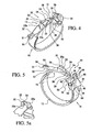
- Figure 4, 5 and 5a are various perspective views of a gastric band in accordance with the present invention.
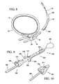
- Figures 6, 7 and 8 show the various steps in the attachment of the gastric band using the present suture tab extender.
- Figure 9 is a perspective view of a suture tab extender in accordance with a further embodiment.
- Figure 10 is a perspective view of a suture tab extender in accordance with an alternate embodiment.
- Figures 11, 12, 13 and 14 respectively show a perspective view of a balloon, a perspective view of a belt, a cross sectional view of a gastric band and a perspective view of the gastric band in accordance with another embodiment of the present invention.
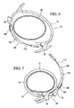
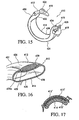
- Figures 15 and 16 respectively show a perspective view of a gastric band and a cross sectional view of the gastric band in accordance with an alternate embodiment of the present invention.
- Figure 17 is a cross sectional view of a gastric band in accordance with another embodiment of the present invention.
- Figures 18, 19, 20 and 21 respectively show a perspective view of a belt, a perspective view of a balloon, a cross sectional view of a gastric band and a perspective view of the gastric band in accordance with yet another embodiment of the present invention.
- Figures 22 to 31 show various embodiments of a balloon type gastric band with differing supply tube locations.
- Figures 32 to 43 show various embodiments of suture tab extenders with differing attachment structures.
- The detailed embodiments of the present invention are disclosed herein. It should be understood, however, that the disclosed embodiments are merely exemplary of the invention, which may be embodied in various forms. Therefore, the details disclosed herein are not to be interpreted as limiting, but merely as the basis for the claims and for teaching one skilled in the art how to make and/or use the invention.
- With reference to Figures 1 and 2, a removable
suture tab extender 100 for use in conjunction with agastric band 10 is disclosed. Theextender 100 is designed to enhance usage ofgastric bands 10 and aid with the use of the gastricband latching mechanism 20. In particular, theextender 100 provides a mechanism for assisting in the passage of the first latchingmember 22 of thelatching mechanism 20 through the second latchingmember 26 of thelatching mechanism 20 by either threading or pushing the first latchingmember 22 through the second latchingmember 26 or by inserting a grasper through the second latchingmember 26, grasping the tip of theextender 112, and pulling it back through the second latchingmember 26 to lock. - To attach the
extender 100 to thegastric band 10, thetether strap 108 of theextender 100 is threaded through anaperture 38 in the tip of thelatching mechanism 20. Thistether strap 108 is then glued to the rest of theextender 100 inside acoupling indent 110. In accordance with an alternate embodiment, and with reference to Figure 10, theextender 300 may be provided with apocket 311 positioned at the end of thecoupling indent 310 in which thetether strap 308 may be glued. - The
extender 100 is easily removed or cut apart from thegastric band 10 once thegastric band 10 is properly positioned and secured about the stomach, thereby minimizing the risk of "sharp" band edges if the band itself was cut. To remove theextender 100, thetether strap 108 is cut between theaperture 38 in thetip 36 of thegastric band 20 and thecoupling indent 110 containing the gluedtether strap 108. This allows theextender 100 to be removed in one piece, leaving thegastric band 100 completely intact without any "sharp" band edges. - The
extender 100 may further be provided with a recess 109 (see Figure 2) on theextender 100 for inserting scissors between thetip 36 of thegastric band 20 and thetether strap 108 to better facilitate cutting off theextender 100. Theextender 100 is completely removed from the body after it has been cut off of thegastric band 10. Theextender 100 also allows for the creation of an interim lock permitting adjustment around the stomach before final locking of thelatching mechanism 20. Although a preferred embodiment has the extender cut off for one piece removal from the gastric band body, an alternate embodiment would entail leaving the extender in place on the gastric band and utilizing the interim lock (that is, theretention member - In practice, and with reference to Figure 3, the present
suture tab extender 100 is secured to thefirst end 14 of thegastric band 10 adjacent the first latchingmember 22 to form a single band/extender functional unit. Thereafter, thegastric band 10, with theextender 100 secured thereto, is inserted behind the stomach. Thefirst latching member 22 of thelatching mechanism 20, as well as theextender 100, are then pushed or pulled through the second latchingmember 26 of thelatching mechanism 20. The addition of the presentsuture tab extender 100 provides a longer region for grasping and manipulation of the first latchingmember 22 as it is passed about the stomach and through the second latchingmember 26. - In accordance with a preferred embodiment, and as will be discussed below in greater detail, the
suture tab extender 100 is an elongated, elastomeric component that attaches to thefirst end 14 of thegastric band 10 to assist in mating and locking the first latchingmember 22 with the second latchingmember 26. Theextender 100 is preferably attached to atab 24 at thefirst end 14 of thegastric band 10 to hold theextender 100 in place. Theextender 100 is removable with one cut through thetether strap 108 on theextender 100 and incorporates a recess or an open recess, for example, a cuplike feature, 106 for coupling thefirst end 14 ofgastric band 10 andextender 100 close together so as to move as an integral unit. - More specifically, and as will be greater appreciated based upon the following disclosure, the
tab 24 of thegastric band 10 is positioned within therecess 106 of theextender 100 and is safely and securely coupled thereto using atether strap 108. In addition, and in accordance with the preferred embodiment, the second end of the extender may include asuture loop 105 for compatibility with a Goldfinger-like device 150. As those skilled in the art will certainly appreciate, the Goldfinger-like device 150 assists in passing thegastric band 20 through the retro-gastric tunnel. Alternately, for surgeons who use other devices for passing thegastric band 20 through the retro-gastric tunnel, the gripping section, or flat tip, 112 of theextender 100 is compatible with these band-passing devices as well. In general a Goldfinger instrument is an articulating band passing device used to perform blunt dissection behind the stomach before passing the gastric band. It is articulated and fed behind the stomach. In the tip of the Goldfinger instrument there is a notch that a suture loop can catch on. Once the suture is caught, the Goldfinger instrument is pulled out of the retro-gastric tunnel and the suture loop pulls the band with it. Alternately, to facilitate use with these other band passing-devices, a length of the extender may be round (like tubing) behind the flat tip so that the extender is easier to orient. - The
removable extender 100 is designed for use with a variety of gastric bands. By way of example, the extender is designed for use with gastric bands as disclosed in commonly ownedU.S. Patent Application Serial No. 11/182,072, filed July 15, 2005 - In general, and with reference to Figures 4, 5 and 5a, the
gastric band 10 includes aband body 12 having afirst end 14 and a secondopposite end 16. Theband body 12 andlatching mechanism 20 are preferably manufactured from silicone. Although, and as will be discussed below in greater detail, the gastric band is a balloon type gastric band, the present latching mechanism may be used in conjunction with a variety of band structures without departing from the spirit of the present invention. - As briefly mentioned above, the
gastric band 10 is shaped and dimensioned to circumscribe the stomach at a predetermined location reducing the size of the stomach. Thegastric band 10 employs aflexible latching mechanism 20 capable of locking and unlocking without destruction of thelatching mechanism 20 or significant reduction in retention capabilities after re-locking. The first and second ends 14, 16 respectively act as both male and female members depending on the direction of motion and intent to lock or unlock thelatching mechanism 20 of the presentgastric band 10. - The
first end 14 includes a shell member, or first latching member, 22 generally composed of a hollow, half-moon shaped shell with atab 24 for gripping and pulling through a collar member, or second latching member, 26 composed of a semi-circular shapedaperture 30 on thesecond end 16. The half-moon shell of the first latchingmember 22 collapses as it is pulled or pushed through thecollar member 26 by a grasper. Thecollar member 26 includes atongue 28 such that theshell member 22 slides through the semi-circular shapedaperture 30 and under thetongue 28 during latching. Once theshell member 22 passes thetongue 28, the roles change. Thefirst end 14 functions as a female component when theshell member 22 resiliently returns to its original shape and is allowed to slide back onto the second end 16 (now a male component) and over thetongue 28. As such, theshell member 22 functions as both a male component and female component during operation of thelatching mechanism 20 and thecollar member 26 functions as both a male component and female component during operation of thelatching mechanism 20; that is, theshell member 22 functions as a male component during insertion through thecollar member 26 and a female component thereafter when thetongue 28 is seated therein. Unlocking is achieved by employing graspers to pull thefirst end 14 forward away from thesecond end 16 removing the tongue from theshell member 22. The M-shape of theshell member 22 permits it to collapse and move under thetongue 28 and through thecollar member 26. - More particularly, the
shell member 22 at thefirst end 14 of thegastric band 10 is generally a half-moon shaped shell with an open,wide end 32 tapering toward anarrow end 34 adjacent thetip 36 of thefirst end 14. Theshell member 22 is substantially hollow and is formed from a material, for example, silicone, which permits compression and expansion thereof. - Referring to Figure 5a, the
shell member 22 is formed with a substantially M-shapedouter surface 23a when viewed from thewide end 32 thereof. That is, the outer surface of theshell member 22 has a substantially M-shaped profile, while theinner surface 23b of theshell member 22 adjacent thewide end 32 has a substantially smooth semi-circular profile. The single M-shaped profile has been found to improve flexibility and control as theshell member 22 is passed through thecollar member 26. In addition, the inclusion of the M-shape in thewide end 32 of theshell member 22 permits ease of unlocking, as it will be easier and more controllable for one to compress theshell member 22. - The
shell member 22 is slid through thecollar member 26 as discussed above. Thereafter, thecenter 54 of the M-shapedwide end 32 returns to its original shape and fits over thetongue 28. When thegastric band 10 is unlatched, theshell member 22 is pulled forward away from thecollar member 26 and the M-shapedshell member 22 permits it to move under thetongue 28 and through thecollar member 26. The preformed shape of theshell member 22 not only acts as a guiding feature for thetongue 28 to slide over theshell member 22 during unlocking, but will also allow theshell member 22 to more easily slide back through theaperture 30 of thecollar member 26. - An
aperture 38 is formed within thetab 24 adjacent thetip 36 of thefirst end 14 and thenarrow end 34 of theshell member 22. Theaperture 38 is shaped and dimensioned for receipt of a suture or grasper commonly used in the installation of gastric bands. In addition, thetab 24 is formed withprotrusions 39 assisting in grabbing thetab 24 during locking and unlocking. - Also at the
first end 14, but on the opposite side of theshell member 22 from theaperture 38 and adjacent thewide end 32 of theshell member 22 is a rearwardly extending grippingmember 51. The grippingmember 51 is shaped and dimensioned to permit dual directional access for locking and unlocking of thelatching mechanism 20. More particularly, the grippingmember 51 includesprotrusions 56 along the top andbottom surfaces member 51 is further formed with an "hour glass" shape having a reinforcedcentral section 57. The reinforcedcentral section 57 allows for gripping in a second directional orientation. - Secure fastening of the
shell member 22 with thecollar member 26 is achieved by ensuring that after theshell member 22 compresses while passing through thecollar member 26, theshell member 22 returns to its original shape and thewide end 32 of theshell member 22 abuts with thefirst edge 46 of thecollar member 26. - Latching is further enhanced by providing the
collar member 26 with atongue 28 extending from thecollar member 26 away from thetip 50 of thesecond end 16. Thetongue 28 is shaped and dimensioned to seat within thewide end 32 of theshell member 22 after theshell member 22 has passed through thecollar member 26 and thegastric band 10 is tensioned as the first and second ends 14, 16 are drawn toward each other with theshell member 22 straining to move back through thecollar member 26 toward an unlatched positioned. With this in mind, thetongue 28 may be downwardly oriented such that it slides with theshell member 22 in a convenient and reliable manner. Thetongue 28 may be distinctly colored to provided an indication as to whether thelatching mechanism 20 is properly locked. - Gripping of the
second end 16 is further enhanced through the provision of a forward facing grippingmember 58, that is, a gripping member facing thetip 50 of thesecond end 16. The forward facing grippingmember 58 is shaped and dimensioned to permit dual directional access for locking and unlocking of thelatching mechanism 20. More particularly, the grippingmember 58 includesprotrusions 59 along the top andbottom surfaces protrusions 59 facilitate gripping thereof along a first directional orientation. The grippingmember 58 is further formed with an "hour glass" shape having a reinforcedcentral section 60. The reinforcedcentral section 60 allows for gripping in a second directional orientation. - The gripping
member 58 is shaped and dimensioned to receive and center theshell member 22 as it passes through thecollar member 26. The grippingmember 58 also assists in compressing theshell member 22 as it passes through thecollar member 26. - In accordance with a preferred embodiment of the present invention, the gastric band is a balloon-type gastric band as shown in Figures 11 to 16. With this in mind, the
gastric band 410 is generally composed of a reinforcingbelt 412 to which anelongated balloon 414 is secured. Thebelt 412 includes afirst end 416 and asecond end 418 to which the first andsecond latching members belt 412 further includes aninner surface 428 and anouter surface 430. Theouter surface 430 is substantially smooth and forms a substantial portion of theouter surface 431 of thegastric band 410 when it is secured about a patient's stomach. Theinner surface 428 of thebelt 412 is shaped and dimensioned for attachment to theouter surface 438 of theballoon 414. - With regard to the
balloon 414, it also includes afirst end 432, asecond end 434, aninner surface 436 and anouter surface 438. Theinner surface 436 is substantially smooth and is shaped and dimensioned for engaging the patient's stomach when thegastric band 410 is secured thereto. Theouter surface 438 of theballoon 414 is shaped and dimensioned for coupling with theinner surface 428 of thebelt 412. - Referring to Figures 11 to 16, the
belt 412 andballoon 414 may be respectively coupled by either overmolding or separate molding with subsequent adhesive bonding (similar numerals are used for the different embodiments). Regardless of the manufacturing technique, theouter surface 438 of theballoon 414 is formed with agroove 439 shaped and dimensioned for receiving thebelt 412. Referring to Figures 15 and 16, wherein thebelt 412 is adhesively bound to theballoon 414, thegroove 439 is formed with aglue gap 439a shaped and dimensioned for receipt of a small amount of adhesive without adversely affecting the position of thebelt 412 within thegroove 439. - In accordance with an alternate embodiment, and with reference to Figure 17, it is contemplated the balloon 414' and the belt 412' may be coupled by adding a layer of uncured material 413' (similar in composition to components) between the balloon 414' and belt 412', and curing them together. In addition, a layer of reinforcing structure 415' (mesh, dissimilar material, or higher durometer silicone material) is contained within the layer of uncured material 413'. This reinforcing structure 415' is encapsulated within the device upon assembly and curing, and provide additional structure or different mechanical properties to the product.
- In addition, and with reference to Figures 18 to 21, yet a further
gastric band 410" construction is contemplated in accordance with the present invention. In accordance with this embodiment, thebelt 412" is secured along aninternal surface 417" of theballoon 414", with theouter surface 428" of theballoon 414" forming the exposedouter surface 430" of thegastric band 410". As with the embodiments disclosed above, theinternal surface 417" is formed with agroove 439" shaped and dimensioned for receiving thebelt 412". Secure positioning of thebelt 412" within thegroove 439" is achieved through provision of aglue gap 439a" along thegroove 439" and a retainingsnap 439b" along the length of thegroove 439". Theglue gap 439a" is substantially similar to that employed in accordance with the embodiment disclosed with reference to Figures 16 and 17. - As to the retaining
snap 439b", thegroove 439" is constructed with opposed, inwardly directedprotrusions 439c" shaped and dimensioned to engage thebelt 412", and temporarily retain thebelt 412" within thegroove 439", while the glue used to couple thebelt 412" andballoon 414" cures during the gluing operation. More particularly, the inwardly directedprotrusions 439c" are shaped and dimensioned to wrap about thebelt 412" in a manner holding it within thegroove 439c". - In accordance with a preferred embodiment, the
belt 412" is positioned within theballoon 414" in the following manner. Thebelt 412" is threaded through one of theballoon openings 433", 435" on eitherend 432", 434" of theballoon 414". The retainingsnap 439b, specifically protrusions 439c", on thegroove 439 of theballoon 414" temporarily hold the components together while they are being glued via a long needle inserted between theballoon 414" and thebelt 412". Alternately, it is contemplated the balloon can be overmolded onto the belt. - In accordance with preferred embodiments, and as briefly discussed above, the balloon and belt may be secured together by either adhesive bonding, comolding, overmolding or mechanical connection (for example, coupling sleeves), which secures the balloon and belt in a manner resulting in the coupling of these distinct gastric band components. Where the belt and balloon are overmolded, a
plug 415 would be used to close the core outlet in the balloon for the overmold and theplug 415 would be integral to the gastric band structure (see Figs. 14 &15). As those skilled in the art will certainly appreciate, co-molding is essentially the same procedure as overmolding, but materials of different properties are shot in the mold at the same time. As with overmolding, comolding requires a plug to close the core outlet in the balloon. - Regardless of how the product is molded or assembled together, the belt and balloon components may consist of the same materials or different materials (material durometer, fillers such as BaSO4, TiO2, colorants, etc.). In addition, features within the same component (i.e. the locking features or end caps) may vary in composition. These features may be adhered to the rest of the product with adhesive, mechanical fastening (i.e., snap fits), welding, co-molding, or overmolding. Although the belt is disclosed as being secured to an outer surface of the balloon, it is contemplated the belt may be internal or external to the balloon surface or integrated into the balloon, without departing from the spirit of the present invention.
- For assembly methods allowing the adherence of different components (that is, adhesive bonding, mechanical connection, overmolding), unique belt and balloon components may be combined to provide variable configurations. For example, belts with different locking mechanisms may be interchanged with balloons of different lengths to provide the possibility of multiple combinations of products.
- The
balloon 414 is constructed to enhance contact with the stomach wall when applied thereto. With this in mind, and as will be discussed below in greater detail, theballoon 414 is constructed as a precurved, low pressure, high volume balloon. Theballoon 414 is constructed to maintain a soft and flexible surface (low pressure) when applied to the stomach tissue. Theballoon 414 is also constructed to provide 360 degree coverage to prevent tissue pinching or discontinuities in stomach shape, and, as such, may employ the balloon construction disclosed in commonly ownedU.S. Patent Application Serial No. 11/182,070 balloon 414 is further constructed such that it reaches it fully inflated and encircling configuration with minimal "folds". In addition, theballoon 414 is constructed to exhibit no folds or creases (single axis, not dual axis) when all fluid is evacuated therefrom. - With the foregoing in mind, the
balloon 414 employed in accordance with a preferred embodiment of the present application is constructed of an elastomeric material. Due to the design of this balloon, it does not inflate or expand in a manner causing high strain in balloon when filled during gastric band adjustment. Rather, theballoon 414 is adapted to receive a large volume of fluid under a relatively low pressure. In this way, theballoon 414 receives fluid during application, but does not inflate or expand in a traditional manner creating strain along the walls of theballoon 414. In other words, when theballoon 414 is filled up to the volume recommended to achieve maximum stomach restriction, there is no expansion of the balloon material. Instead, theballoon 414 fills to some percentage of its total theoretical volume (that is, maximum fill volume). Since theballoon 414 is not filled even close to its maximum fill volume, it remains low pressure, allowing theballoon 414 to conform to the stomach rather than the stomach to a rigid balloon. - In accordance with a preferred embodiment of the present invention, the
balloon 414 is designed with a maximum capacity of between approximately 10 cc and approximately 18 cc, and preferably 18 cc, although it will be fully filled for functioning in accordance with the present invention to achieve the smallest stoma size with approximately 9 cc to approximately 12 cc, and preferably 9 cc. By providing aballoon 414, which is not at its capacity when properly filled for functioning, the softness and conformance of the balloon is improved. While specific volumes are disclosed in accordance with a preferred embodiment of the present invention, those skilled in the art will appreciate the filling volumes may be varied without departing from the spirit of the present invention. - In addition, the
balloon 414 is fabricated such that it exhibits a curved configuration when unstressed. Although a variety of curvatures are possible within the spirit of the present invention, the curved configuration is designed to offer a radius of curvature of approximately 0.5 inches to approximately 1.5 inches. In addition, it is contemplated the balloon may have a varying radius as it extends about its length. In general, the balloon curvature is designed to approximate the curvature required to bring the first andsecond latching members balloon 414 is unbiased and left to assume a relaxed configuration. By fabricating theballoon 414 with an inherent curvature, folds created upon the application of fluid are substantially decreased. With this in mind, the belt is similarly pre-curved to reduce folds and approximate the first andsecond latching members - As those skilled in the art will certainly appreciate, the
belt 412 is constructed to have a curvature approximately the same that of theballoon 414 such that undesirable tension between thebelt 412 andballoon 414 is reduced. In addition, and in consideration of the precurved nature of thebelt 412, thebelt 412 readily conforms to the outer surface of the stomach and thebelt 412. - Contact with the stomach tissue is further enhanced by providing the
balloon 414 with a concave cross-section along the balloonsinner surface 436. This cross sectional configuration helps to facilitate evacuation and straightening thereof. - By implementing the structural criteria outlined above, the
balloon 414 deflates with no creases or bulges forming on theinner surface 436 of theballoon 414, a low pressure andpre-curved balloon 414 is achieved and theballoon 414 changes shape when it is filling (zip-lock bag filling up). As to the change in shape, theballoon 414 is constructed such that it has a relatively wider and flatter cross section prior to filling along a cross section transverse to the longitudinal axis of theballoon 414. When theballoon 414 is subsequently filled during application to the stomach of a patient, the transverse cross sectional shape of theballoon 414 changes to that of a rounder balloon exhibiting a narrower cross section with a greater distance between the inner andouter surfaces - As those skilled in the art will certainly appreciate, a supply tube is used to connect the internal cavity of the balloon of the gastric band with a pressurized fluid source. The utilization of the tube with a remote fluid source allows for controlled inflation and deflation of the balloon in a predetermined manner. The exact position of the tube is important in that the surgeon does not want tubing to be a visual obstruction during locking and/or other manipulation of the gastric band. In addition, once placement of the gastric band is complete, the tube should not cause irritation to surrounding tissue (for example, sticking directly into the liver or spleen). Surgeons also do not want to pull the tube through a retro-gastric tunnel, since they cannot easily see if the tissue is being damaged. The tube should also be able to act as a safe grasping location for manipulation of the gastric band, the tube must not kink at the junction to the gastric band and prevent fluid flow, and the tube location should facilitate passage of the band through a small trocar.
- With this in mind, and in accordance with various preferred embodiments of the present invention, different tube placements are shown with reference to Figures 22 to 31. As each these various embodiments show, the tube is positioned at an end of the gastric band. By positioning the tube at an end of the gastric band it has been found that forces upon the tube, gastric band, and, ultimately the stomach, are reduced. This positioning also enhances the ability of the tube and gastric band to flex for insertion and expand to its original shape upon deployment.
- Referring to Figure 22, the
tube 540 is oriented to exit thegastric band 510 from the outer surface thereof. In accordance with a preferred embodiment of this design, thetube 540 is positioned such that is comes out theouter surface 531 of thegastric band 510 just below alongitudinally extending midline 542 of thegastric band 510. Thetube 540 is positioned so that is placed clear of thelatching mechanism 520 and obliquely angled relative to the longitudinal axis (in accordance with a preferred embodiment at an angle of approximately 34°) of thegastric band 510 to allow easy insertion through a trocar. - Referring to Figure 23, the
tube 640 is molded on thesecond end 634 of theballoon 614. In particular, thetube 640 is molded at the very end of theballoon 614, and is integrated into the balloon shape. As with the prior embodiment, thetube 640 is obliquely oriented relative to the longitudinally axis of thegastric band 610 and is similarly positioned below a longitudinally extending midline of thegastric band 610. The offset allows for the balloon ends 632, 634 to meet without interference from thetube 640. - A further embodiment is shown with reference to Figure 24, wherein the
tube 740 exits theballoon 714 off alateral side 744, that is, a very bottom surface, of theballoon 714 as it is positioned within the patient. Thetube 740 entry point is substantially aligned with thesecond latching member 726 relative to the longitudinal axis of thegastric band 710. As with the prior embodiments, thetube 740 is obliquely oriented relative to the longitudinally axis of thegastric band 710. - As shown in Figures 25 and 26, the
tube 840 connection is integrated into one of the sides of the latching members. In accordance with the disclosed embodiment, it is integrated into thesecond latching member 826, although it is contemplated it could be integrated with thefirst latching member 822 without departing from the spirit of the present invention. Thetube 840 enters thesecond latching member 826 and extends therethrough into the body of theballoon 814. Once thetube 840 is inside the body of theballoon 814, it angles to the centerline (or midline 842) of theballoon 814 for even filling of saline. Thetube 840 is also obliquely oriented relative to the longitudinally axis of thegastric band 810 and is similarly positioned below alongitudinally extending midline 842 of thegastric band 810. The offset allows for the balloon ends 832, 834 to meet without interference from thetube 840. - Yet other embodiments are shown respectively with reference to Figures 27 and 28. In accordance with one embodiment as shown in Figure 27, the
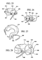
tube 940 is molded into theplug 946 used to cap the core portion of theballoon 914. In accordance with the other embodiment as shown in Figure 28, thetube 1040 is molded as an integral portion of thesecond latching member 1026. The fluid passageway, therefore, extends through thetube 1040, intopassageways 1048 formed in thesecond latching member 1026 and ultimately into theballoon 1014. More particularly, once thetube 1040 enters into a bridge of the second latching member 1026 (that is, where thesecond latching member 1026 defines the aperture), it splits into abifurcated tube 1052 that goes into theballoon 1014 via bothwalls 1054 of theaperture 1030 of thesecond latching member 1026. - Still another embodiment is shown in Figures 29 and 30, wherein the
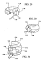
tube 1140 is integrated into one of the sides of thelatching mechanism 1120, preferably, thesecond latching member 1126. Thetube 1140 then runs through agusset 1156 from the back of thesecond latching member 1126 to allow for a low entry angle into theballoon 1114. - Referring to Figure 31, the
tube 1240 entry is integrated into the belt 1212 (and more particularly, the second latching member 1226) to allow for separate molding of thebelt 1212 andballoon 1214. By being attached to thesecond latching member 1226, thetube 1240 could be used to find the location of thelatching mechanism 1220 once the implant has been encapsulated into the fibrous tissue. As with the prior embodiments, thetube 1240 is obliquely oriented relative to the longitudinally axis of thegastric band 1210 and is similarly positioned below alongitudinally extending midline 1242 of thegastric band 1210. The offset allows for the balloon ends 1234 to meet without interference from thetube 1240. - In addition, any of the tubing configurations disclosed with reference to Figures 22 through 31 could incorporate some type of strain relief member to reduce fatigue as the tubing flexes back and forth in the body. Such strain relief would be achieved by positioning a length of thicker material at the tubing entry point into the balloon (see for example 1156 on Figure 29, similarly shown but not called out in Figure 31). The length of thicker material allows the tubing to take a larger curve as it is bent away from the joint between the tube and the balloon. In other words, this length of material that has been thickened increases the stiffness of the tubing in this region to allow the tubing to flex without kinking and moves the point of flexing further away from the vulnerable joint between the band, balloon, and tubing. The strain relief member would be made preferably of silicone, but other materials (plastics, metals, etc.) could also be used. Also, in all of these embodiments, the tubing to could be connected to either the belt or the balloon by any one of multiple manufacturing methods, such as overmolding or assembling and gluing.
- Although the present invention is described for use in conjunction with gastric bands, those skilled in the art will appreciate the above invention has equally applicability to other types of implantable bands. For example, bands are used for the treatment of fecal incontinence. One such band is described in
U.S. Pat. No. 6,461,292 . Bands can also be used to treat urinary incontinence. One such band is described inU.S. Patent Application Publication No. 2003/0105385 . Bands can also be used to treat heartburn and/or acid reflux. One such band is described inU.S. Patent No. 6,470,892 . Bands can also be used to treat impotence. One such band is described inU.S. Patent Application Publication No. 2003/0114729 . - Referring to Figures 1 and 2, the
extender 100 includes an elongated body member having afirst end 102 andsecond end 104. Thefirst end 102 includes anopen recess 106 shaped and dimensioned to receive thetab 24 of the first latchingmember 22 at thefirst end 14 of thegastric band 10. Thefirst end 102 of theextender 100 is further provided with atether strap 108. Thetether strap 108 is shaped and dimensioned for passage through theaperture 38 formed in thetab 24 and ultimate attachment within acoupling indent 110 formed in the outer surface of thefirst end 102 of theextender 100. In this way, thetether strap 108 extending from theextender 100 loops through thetab 24 readily coupling thefirst end 102 of theextender 100 the first latchingmember 22 for selective attachment and detachment. - The
second end 104 of theextender 100 includes agripping section 112 shaped and dimensioned to facilitate gripping thereof as theextender 100 is passed through thecollar member 26 and thegastric band 10 is applied around a patient's stomach. In addition, there is asuture loop 105 for compatibility withGoldfinger instruments 150 as discussed above and the gripping section, or flat end, 112 of theextender 100 is compatible with other band passing devices. Between thefirst end 102 and thesecond end 104 of theextender 100 is formed a laterally extendingretention member 114. Theretention member 114 is semi-circular when viewed along a planar, transverse cross section. Theretention member 114 tapers to widen as it extends toward thefirst end 102 of theextender 100 in a manner creating a surface over which thecollar member 26 may slide during latching for interim attachment of theextender 100 to thecollar member 26. The taper creates anengagement surface 118 which holds thecollar member 26 between the enlargedfirst end 102 of theextender 100 and theretention member 114 when thefirst end 102 of theextender 100 is temporarily latched to thecollar member 26. - Although an extender with a recess and retention member in accordance with a preferred embodiment is disclosed above, the extender may take other forms without departing from the spirit of the present invention. For example, and in accordance with another preferred embodiment shown with reference to Figure 9, the
extension member 200 includes an elongated body member having afirst end 202 andsecond end 204. Thefirst end 202 includes an enclosed, pocket recess, more particularly a pocket, 206 shaped and dimensioned to fully receive thetab 24 of the first latchingmember 22 at thefirst end 14 of thegastric band 10. Thefirst end 202 of theextension member 200 is further provided with atether strap 208. Thetether strap 208 is shaped and dimensioned for passage through theaperture 38 formed in thetab 24 and ultimate attachment within acoupling indent 210 formed in the outer surface of thefirst end 202 of theextension member 200. In this way, thefirst end 202 of theextension member 200 may be readily and selectively secured and detached from the first latchingmember 22. - The
second end 204 of theextension member 200 includes a series ofprotrusions 212 shaped and dimensioned to facilitate gripping thereof as theextension member 200 is passed through thecollar member 26 and thegastric band 10 is applied around a patient's stomach. Thesecond end 204 also includes asuture loop 205 extending therefrom. Between thefirst end 202 and thesecond end 204 of theextension member 200 is formed a laterally extendingretention member 214. Theretention member 214 includes first andsecond engagement members engagement members first end 202 of theextension member 200 in a manner creating a surface over which thecollar member 26 may slide during latching for interim attachment of theextension member 200 to thecollar member 26 prior to complete latching of thegastric band 10 latching mechanism 20 (after which theextension member 200 is detached from the gastric band 10). The taper creates opposed engagement surfaces 220, 222 which hold thecollar member 26 between the enlargedfirst end 202 of theextension member 200 and theengagement members first end 202 of theextension member 200 is temporarily latched to thecollar member 26. - Regardless of the extender construction utilized in accordance with a gastric band, it is important the extender be readily accessed for removal with little possibility for error. The two key issues in removal of an extender revolve around a surgeon's ability to identify the extender, in particular, that part of the extender requiring manipulation for removal thereof, and proceed to remove the extending in accordance with the removal mechanism employed. With this in mind, various embodiments for ensuring clear visualization and convenient cutting have been developed. Any of the embodiments described below can incorporate a visual indicator such as color (on either the entire extender, the tether strap, or the only the region to be cut) or a visible suture to indicate to the surgeons that this is a separate component from the gastric band that should be removed. In addition, these embodiments also provide various means in which the extender may be attached to the gastric band (tether strap, suture, etc.).
- More particularly, and with reference to Figures 32, 33, 35 and 36, the
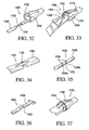
extender 1300 adjacent thefirst end 1302 thereof or thetether strap extender ramps tether strap extender ramp tether strap first end 1302 and the surgeon is able to readily visualize the location of thetether strap ramp tether strap extender bumps tether strap 1508 and define an area at which a surgeon should cut thetether strap 1508. - In addition to improving visualization of the tether strap, in each embodiment the bumps or ramp raise the tether slightly above the gastric band, increasing the space between the tether and the gastric band to provide an improved passageway for position scissors therein for cutting of the tether and ultimate removal of the extender. Visualization of the cutting location in accordance with this embodiment is enhanced by providing a gap or a
notch tether strap extender extender suture tether strap suture tether strap tether strap aperture 38 of thegastric band tab 24 and wrapped about thegastric band 10 to secure the two components together, thegap - Similarly, and as is seen if Figures 34 and 35, the
tether strap tether strap notch tether strap notch tether - Other embodiments are disclosed with reference to Figures 37, 39 and 40. These embodiments employ a reinforcing member, for example, a
suture extender suture 1734 holds thetether strap 1708 down upon the body thereof. As such, and rather than cutting thetether strap 1708 itself as disclosed above with reference to the various embodiments, the securingsuture 1734 is cut to thereby release thetether strap 1708 for removal of theextender 1700. Alternately, the suture may be used to tie down the strap and as such, secure the tether to the extender without the assistance of adhesive. Although a suture is disclosed as a reinforcing member in accordance with a preferred embodiment, other reinforcing structures, for example, mesh, may be used within the spirit of the present invention. - In another related embodiment shown in Figure 39 and 40, the suture material of the
suture loop 1905 is extended to run the length of theextender 1900 such that thesuture material 1934, extends from thefirst end 1902 of the extender 1900 (substantially replacing the tether of the prior embodiments). This allows theextender 1900 to wrap asuture 1934 through anaperture 38 in the tip of thegastric band 10 and engage aprojection 1936 extending from thefirst end 1902 of theextender 1900. In addition to securing the gastric band in a reliable and convenient manner, this embodiment provides additional benefits in that thesuture 1934 now has a loop at thefirst end 1902 and thesecond end 1904 of theextender 1900. This increases the strength of theextender 1900 because the suture cannot pull out of the extender independent of extender material failure. - Referring to Figure 38, another embodiment is disclosed. In accordance with this embodiment, the
tip 1812 of thegastric band 1810 is seated within therecess 1806 formed in theextender 1800. However, therecess 1806 and thetip 1812 of thegastric band 1810 include a snap feature providing a semi-mechanical locking mechanism between thegastric band 1810 and theextender 1800. Such an embodiment would improve the ability of theextender 1800 to lead and guide thetip 1812 of thegastric band 1810 in concert without twisting or flipping. Such a semi-mechanical locking mechanism could be utilized in conjunction with the other tether securing arrangements as a means for providing redundant securing of the extender to the gastric band. It is further contemplated this embodiment may havesuture 1811 around thetip 1812 of thegastric band 1810 and therecess 1806 of the extender 1800 (like Figure 37) to compress the region where the snapfitting tip 1812 fits within therecess 1806 of theextender 1800. When the surgeon cuts and removes the surroundingsuture 1811, they can then expand theflexible silicone extender 1800 over the snapfitting tip 1812 on the front of the tab to separate theextender 1800 from thegastric band 1810 in one piece. - Further and with reference to Figure 41, a
suture 2034 is similarly utilized in securing theextender 2000 to the gastric band. However, theprojection 2036 to which theextender 2000 is secured is designed such that it may be peeled away. As such, when it is desired to remove theextender 2000, one need only peel away theprojection 2036 to release theextender 2000 and thereby no cutting is required. - Referring to Figure 42, another embodiment is disclosed. In accordance with this embodiment, the
tether 2108 of theextender 2100 is lengthened to allow theglue position 2138 to be moved a forward position on theopen recess 2106extender 2100. This allows thetether 2108 of theextender 2100 to be cut atline 2140 to remove theextender 2100. More particularly, theopen recess 2106 includes a forward and 2106a positioned toward the middle of theextender 2100 and arearward position 2106b positioned near thefirst end 2102 of theextender 2100. Theglue position 2138 is at theforward end 2106a. This is still a one-piece removal, only the length of the location for cutting has changed. This embodiment allows thetether 2108 to bow for improved access with scissors or other tools when the front of the extender is flexed upwardly since the tether is only glued at oneend 2106a. - In accordance with yet another embodiment, and with reference to Figure 43, a flange or
stopper 2242 is positioned at a preset point along the length of thetether 2208. This enables positioning of thegap 2232 in thetether 2208 relative to the position of theextender 2200 where thesuture 2234 needs to be cut and to avoid having suturing contact with the gastric band hole during band pulling. Thestopper 2242 is positioned to engage the tab surrounding the aperture so as to limit the extent to which thetether 2208 may pass therethrough. The portion of thetether 2208 adjacent thestopper 2242 may be tapered and the section that is positioned inside the aperture of the gastric band can be larger in cross section to provide a snug fit with the hole of the gastric band. As with prior embodiments the tether will includes a gap or notched section for identification and cutting thereof. In addition, the suture loop runs fully through the extender and may be utilized by tying it into a knot that is molded within the enlarged section of the stopper so as to improve the strength of the extender tether. - While the preferred embodiments have been shown and described, it will be understood that there is no intent to limit the invention by such disclosure, but rather, is intended to cover all modifications and alternate constructions falling within the spirit and scope of the invention.
Claims (11)
- A removable suture tab extender for a gastric band, the extender shaped and dimensioned for selective attachment to a first end of the gastric band, the gastric band including a latching mechanism composed of a first latching member positioned at the first end of the gastric band and a second latching member positioned at a second end of the gastric band, the gastric band extender comprising:an elongated body member including a first end and a second end;the first end of the elongated body member is shaped and dimensioned for coupling with the first latching member; andthe second end of the elongated body member includes a gripping section shaped and dimensioned to facilitate gripping thereof as the gastric band extender is passed through the second latching member.
- The removable suture tab extender according to claim 1, further including a laterally extending retention member positioned between the first end and the second end of the extender.
- The removable suture tab extender according to claim 2, wherein the retention member includes a triangle shaped engagement surface.
- The removable suture tab extender according to claim 3, wherein the engagement surface tapers to widen as it extends toward the first end of the body member in a manner creating a surface over which the second latching member may slide during latching for interim attachment of the gastric band extender to the second latching member.
- The removable suture tab extender according to claim 2, wherein the retention member includes a semi-circular shaped engagement surface.
- The removable suture tab extender according to claim 5, wherein the engagement surface tapers to widen as it extends toward the first end of the body member in a manner creating a surface over which the second latching member may slide during latching for interim attachment of the gastric band extender to the second latching member.
- The removable suture tab extender according to claim 1, wherein the shaped and dimensioned first end of the elongated body member is a recess which mates with the first end of the gastric band.
- The removable suture tab extender according to claim 1, wherein the shaped and dimensioned first end of the elongated body member is an open recess which mates with the first end of the gastric band.
- The removable suture tab extender according to claim 1, wherein the first latching member includes a tab, and the recess is shaped and dimensioned for receiving the tab. - this recess allows the band and removable suture tab extender to move as a single functional unit.
- The removable suture tab extender according to claim 1, wherein the first end of the body member is further provided with a tether strap.
- A gastric band and suture tab extender, comprising:a gastric band body including a latching mechanism composed of a first latching member positioned at a first end of the gastric band body and a second latching member positioned at a second end of the gastric band body;a suture tab extender releasable secure to the first end of the gastric band body, the suture tab extender includes:an elongated body member including a first end and a second end;the first end of the elongated body member is shaped and dimensioned for coupling with the first latching member; andthe second end of the elongated body member includes a gripping section shaped and dimensioned to facilitate gripping thereof as the gastric band extender is passed through the second latching member.
Applications Claiming Priority (1)
| Application Number | Priority Date | Filing Date | Title |
|---|---|---|---|
| US11/364,361 US7364542B2 (en) | 2005-07-15 | 2006-03-01 | Gastric band suture tab extender |
Publications (3)
| Publication Number | Publication Date |
|---|---|
| EP1829505A2 true EP1829505A2 (en) | 2007-09-05 |
| EP1829505A3 EP1829505A3 (en) | 2008-05-28 |
| EP1829505B1 EP1829505B1 (en) | 2011-07-27 |
Family
ID=38179745
Family Applications (1)
| Application Number | Title | Priority Date | Filing Date |
|---|---|---|---|
| EP07250830A Not-in-force EP1829505B1 (en) | 2006-03-01 | 2007-02-28 | Gastric band suture tab extender |
Country Status (9)
| Country | Link |
|---|---|
| US (1) | US7364542B2 (en) |
| EP (1) | EP1829505B1 (en) |
| JP (1) | JP5106883B2 (en) |
| CN (1) | CN101028214B (en) |
| AT (1) | ATE517591T1 (en) |
| AU (1) | AU2007200779B2 (en) |
| BR (1) | BRPI0700480B8 (en) |
| CA (1) | CA2579984C (en) |
| HK (1) | HK1108820A1 (en) |
Cited By (8)
| Publication number | Priority date | Publication date | Assignee | Title |
|---|---|---|---|---|
| WO2010013059A1 (en) | 2008-07-31 | 2010-02-04 | Surgical Innovations Limited | Endoscopic surgical instrument |
| US7811298B2 (en) | 2002-08-28 | 2010-10-12 | Allergan, Inc. | Fatigue-resistant gastric banding device |
| FR2944432A1 (en) * | 2009-04-21 | 2010-10-22 | Cie Euro Etude Rech Paroscopie | SURGICAL RING WITH ASSEMBLED CONSTRUCTION |
| FR2944429A1 (en) * | 2009-04-21 | 2010-10-22 | Cie Euro Etude Rech Paroscopie | Surgical ring e.g. annuloplasty ring, for biological organ e.g. stomach, of patient, has locking units comprising different external coloration so as to visually locate relative positioning defect of units with respect to locking position |
| FR2944433A1 (en) * | 2009-04-21 | 2010-10-22 | Cie Euro Etude Rech Paroscopie | Surgical ring i.e. gastric ring, for stomach or esophagus of patient, for treating obesity, has gripping tab extending from female unit, where tab and external face of side wall are made of material different hardnesses |
| US7946976B2 (en) | 2004-03-23 | 2011-05-24 | Michael Gertner | Methods and devices for the surgical creation of satiety and biofeedback pathways |
| US7963907B2 (en) | 2004-03-23 | 2011-06-21 | Michael Gertner | Closed loop gastric restriction devices and methods |
| EP2468218A1 (en) * | 2010-12-23 | 2012-06-27 | Q Medical International AG | Medical restriction device for hollow organs of a body |
Families Citing this family (81)
| Publication number | Priority date | Publication date | Assignee | Title |
|---|---|---|---|---|
| US7338433B2 (en) | 2002-08-13 | 2008-03-04 | Allergan, Inc. | Remotely adjustable gastric banding method |
| ES2366188T5 (en) * | 2003-09-15 | 2017-07-11 | Apollo Endosurgery, Inc | Implantable device fixation system |
| CN101507619A (en) | 2004-01-23 | 2009-08-19 | 阿勒根公司 | Implantable device fastening system and methods of use |
| ATE526887T1 (en) * | 2004-01-23 | 2011-10-15 | Allergan Inc | DETACHABLE, ONE-PIECE, ADJUSTABLE STOMACH BAND |
| US7811299B2 (en) | 2004-03-08 | 2010-10-12 | Allergan, Inc. | Closure system for tubular organs |
| EP1732635B1 (en) | 2004-03-18 | 2011-07-27 | Allergan, Inc. | Apparatus for volume adjustment of intragastric balloons |
| US7255675B2 (en) * | 2004-03-23 | 2007-08-14 | Michael Gertner | Devices and methods to treat a patient |
| US20060195139A1 (en) * | 2004-03-23 | 2006-08-31 | Michael Gertner | Extragastric devices and methods for gastroplasty |
| US20050228415A1 (en) * | 2004-03-23 | 2005-10-13 | Michael Gertner | Methods and devices for percutaneous, non-laparoscopic treatment of obesity |
| US7955357B2 (en) | 2004-07-02 | 2011-06-07 | Ellipse Technologies, Inc. | Expandable rod system to treat scoliosis and method of using the same |
| US8251888B2 (en) | 2005-04-13 | 2012-08-28 | Mitchell Steven Roslin | Artificial gastric valve |
| US8298133B2 (en) * | 2005-07-15 | 2012-10-30 | Ethicon Endo-Surgery, Inc. | Gastric band composed of different hardness materials |
| US7618365B2 (en) * | 2005-07-15 | 2009-11-17 | Ethicon Endo-Surgery, Inc. | Method of implating a medical device using a suture tab extender |
| US7798954B2 (en) | 2006-01-04 | 2010-09-21 | Allergan, Inc. | Hydraulic gastric band with collapsible reservoir |
| US8043206B2 (en) | 2006-01-04 | 2011-10-25 | Allergan, Inc. | Self-regulating gastric band with pressure data processing |
| US7862502B2 (en) | 2006-10-20 | 2011-01-04 | Ellipse Technologies, Inc. | Method and apparatus for adjusting a gastrointestinal restriction device |
| US20080287976A1 (en) | 2007-05-14 | 2008-11-20 | Weaner Lauren S | Gastric band with engagement member |
| US8317676B2 (en) | 2007-05-14 | 2012-11-27 | Ethicon Endo-Surgery, Inc. | Gastric band with contrasting supply tube |
| US8357080B2 (en) | 2007-05-14 | 2013-01-22 | Ethicon Endo-Surgery, Inc. | Tissue contrasting gastric band |
| US11202707B2 (en) | 2008-03-25 | 2021-12-21 | Nuvasive Specialized Orthopedics, Inc. | Adjustable implant system |
| US9023063B2 (en) | 2008-04-17 | 2015-05-05 | Apollo Endosurgery, Inc. | Implantable access port device having a safety cap |
| CN102099078A (en) * | 2008-04-17 | 2011-06-15 | 阿勒根公司 | Implantable access port device and attachment system |
| EP2320836B1 (en) * | 2008-06-11 | 2015-08-12 | Apollo Endosurgery, Inc. | Implantable pump system |
| WO2010042493A1 (en) | 2008-10-06 | 2010-04-15 | Allergan, Inc. | Mechanical gastric band with cushions |
| US20100185049A1 (en) | 2008-10-22 | 2010-07-22 | Allergan, Inc. | Dome and screw valves for remotely adjustable gastric banding systems |
| US8382756B2 (en) | 2008-11-10 | 2013-02-26 | Ellipse Technologies, Inc. | External adjustment device for distraction device |
| US9278019B2 (en) | 2009-04-03 | 2016-03-08 | Metamodix, Inc | Anchors and methods for intestinal bypass sleeves |
| US8702641B2 (en) | 2009-04-03 | 2014-04-22 | Metamodix, Inc. | Gastrointestinal prostheses having partial bypass configurations |
| CN102387762B (en) | 2009-04-03 | 2014-08-06 | 美特默迪克斯公司 | Modular gastrointestinal prostheses |
| US9173760B2 (en) | 2009-04-03 | 2015-11-03 | Metamodix, Inc. | Delivery devices and methods for gastrointestinal implants |
| US9622792B2 (en) | 2009-04-29 | 2017-04-18 | Nuvasive Specialized Orthopedics, Inc. | Interspinous process device and method |
| IN2012DN00316A (en) * | 2009-07-10 | 2015-05-08 | Metamodix Inc | |
| US8715158B2 (en) | 2009-08-26 | 2014-05-06 | Apollo Endosurgery, Inc. | Implantable bottom exit port |
| US8708979B2 (en) | 2009-08-26 | 2014-04-29 | Apollo Endosurgery, Inc. | Implantable coupling device |
| US8506532B2 (en) * | 2009-08-26 | 2013-08-13 | Allergan, Inc. | System including access port and applicator tool |
| US8882728B2 (en) | 2010-02-10 | 2014-11-11 | Apollo Endosurgery, Inc. | Implantable injection port |
| US20110201874A1 (en) * | 2010-02-12 | 2011-08-18 | Allergan, Inc. | Remotely adjustable gastric banding system |
| US8678993B2 (en) * | 2010-02-12 | 2014-03-25 | Apollo Endosurgery, Inc. | Remotely adjustable gastric banding system |
| US8758221B2 (en) | 2010-02-24 | 2014-06-24 | Apollo Endosurgery, Inc. | Source reservoir with potential energy for remotely adjustable gastric banding system |
| US8764624B2 (en) | 2010-02-25 | 2014-07-01 | Apollo Endosurgery, Inc. | Inductively powered remotely adjustable gastric banding system |
| US8840541B2 (en) | 2010-02-25 | 2014-09-23 | Apollo Endosurgery, Inc. | Pressure sensing gastric banding system |
| US8608642B2 (en) * | 2010-02-25 | 2013-12-17 | Ethicon Endo-Surgery, Inc. | Methods and devices for treating morbid obesity using hydrogel |
| US8939888B2 (en) | 2010-04-28 | 2015-01-27 | Apollo Endosurgery, Inc. | Method and system for determining the pressure of a fluid in a syringe, an access port, a catheter, and a gastric band |
| US20110270024A1 (en) | 2010-04-29 | 2011-11-03 | Allergan, Inc. | Self-adjusting gastric band having various compliant components |
| US9044298B2 (en) | 2010-04-29 | 2015-06-02 | Apollo Endosurgery, Inc. | Self-adjusting gastric band |
| US9028394B2 (en) | 2010-04-29 | 2015-05-12 | Apollo Endosurgery, Inc. | Self-adjusting mechanical gastric band |
| US8992415B2 (en) | 2010-04-30 | 2015-03-31 | Apollo Endosurgery, Inc. | Implantable device to protect tubing from puncture |
| US20110270025A1 (en) | 2010-04-30 | 2011-11-03 | Allergan, Inc. | Remotely powered remotely adjustable gastric band system |
| US20110270021A1 (en) | 2010-04-30 | 2011-11-03 | Allergan, Inc. | Electronically enhanced access port for a fluid filled implant |
| US9226840B2 (en) | 2010-06-03 | 2016-01-05 | Apollo Endosurgery, Inc. | Magnetically coupled implantable pump system and method |
| US8517915B2 (en) | 2010-06-10 | 2013-08-27 | Allergan, Inc. | Remotely adjustable gastric banding system |
| US9248043B2 (en) | 2010-06-30 | 2016-02-02 | Ellipse Technologies, Inc. | External adjustment device for distraction device |
| US20120041258A1 (en) | 2010-08-16 | 2012-02-16 | Allergan, Inc. | Implantable access port system |
| US9211207B2 (en) | 2010-08-18 | 2015-12-15 | Apollo Endosurgery, Inc. | Power regulated implant |
| US8698373B2 (en) | 2010-08-18 | 2014-04-15 | Apollo Endosurgery, Inc. | Pare piezo power with energy recovery |
| US20120059216A1 (en) | 2010-09-07 | 2012-03-08 | Allergan, Inc. | Remotely adjustable gastric banding system |
| US20120065460A1 (en) | 2010-09-14 | 2012-03-15 | Greg Nitka | Implantable access port system |
| US8961393B2 (en) | 2010-11-15 | 2015-02-24 | Apollo Endosurgery, Inc. | Gastric band devices and drive systems |
| WO2012112396A2 (en) | 2011-02-14 | 2012-08-23 | Ellipse Technologies, Inc. | Device and method for treating fractured bones |
| US8725435B2 (en) | 2011-04-13 | 2014-05-13 | Apollo Endosurgery, Inc. | Syringe-based leak detection system |
| US8821373B2 (en) | 2011-05-10 | 2014-09-02 | Apollo Endosurgery, Inc. | Directionless (orientation independent) needle injection port |
| US8663255B2 (en) * | 2011-08-09 | 2014-03-04 | Ethicon Endo-Surgery, Inc. | Gastric band with overmold |
| US8801597B2 (en) | 2011-08-25 | 2014-08-12 | Apollo Endosurgery, Inc. | Implantable access port with mesh attachment rivets |
| US10743794B2 (en) | 2011-10-04 | 2020-08-18 | Nuvasive Specialized Orthopedics, Inc. | Devices and methods for non-invasive implant length sensing |
| US9199069B2 (en) | 2011-10-20 | 2015-12-01 | Apollo Endosurgery, Inc. | Implantable injection port |
| WO2013066946A1 (en) | 2011-11-01 | 2013-05-10 | Ellipse Technologies, Inc. | Adjustable magnetic devices and methods of using same |
| US8858421B2 (en) | 2011-11-15 | 2014-10-14 | Apollo Endosurgery, Inc. | Interior needle stick guard stems for tubes |
| US9089395B2 (en) | 2011-11-16 | 2015-07-28 | Appolo Endosurgery, Inc. | Pre-loaded septum for use with an access port |
| US8876694B2 (en) | 2011-12-07 | 2014-11-04 | Apollo Endosurgery, Inc. | Tube connector with a guiding tip |
| US8961394B2 (en) | 2011-12-20 | 2015-02-24 | Apollo Endosurgery, Inc. | Self-sealing fluid joint for use with a gastric band |
| CN104902854B (en) | 2012-10-29 | 2017-10-03 | 诺威适骨科专科公司 | The adjustable apparatus scorching for treating knee endoprosthesis |
| US10159699B2 (en) | 2013-01-15 | 2018-12-25 | Metamodix, Inc. | System and method for affecting intestinal microbial flora |
| US10751094B2 (en) | 2013-10-10 | 2020-08-25 | Nuvasive Specialized Orthopedics, Inc. | Adjustable spinal implant |
| CN106456215B (en) | 2014-04-28 | 2020-04-10 | 诺威适骨科专科公司 | External adjustment device for adjusting a medical implant |
| BR112017013834A2 (en) | 2014-12-26 | 2019-11-19 | Nuvasive Specialized Orthopedics Inc | distraction systems and methods |
| WO2016134326A2 (en) | 2015-02-19 | 2016-08-25 | Nuvasive, Inc. | Systems and methods for vertebral adjustment |
| BR112018007347A2 (en) | 2015-10-16 | 2018-10-23 | Nuvasive Specialized Orthopedics, Inc. | adjustable devices for the treatment of knee arthritis |
| EP4275631A3 (en) | 2015-12-10 | 2024-02-28 | NuVasive Specialized Orthopedics, Inc. | External adjustment device for distraction device |
| ES2879405T3 (en) | 2016-01-28 | 2021-11-22 | Nuvasive Specialized Orthopedics Inc | Bone transport systems |
| US9622897B1 (en) | 2016-03-03 | 2017-04-18 | Metamodix, Inc. | Pyloric anchors and methods for intestinal bypass sleeves |
| KR102473258B1 (en) | 2016-05-19 | 2022-12-01 | 메타모딕스, 인코포레이티드 | Pyloric Anchor Recovery Tools and Methods |
Citations (4)
| Publication number | Priority date | Publication date | Assignee | Title |
|---|---|---|---|---|
| US4592339A (en) * | 1985-06-12 | 1986-06-03 | Mentor Corporation | Gastric banding device |
| EP1319371A2 (en) * | 2001-12-03 | 2003-06-18 | Alois H. Dr. Götz | Gastric band |
| EP1598020A1 (en) * | 2004-05-20 | 2005-11-23 | Pankaj Jay Pasricha | Medical treatment device |
| US20050277963A1 (en) * | 2004-05-26 | 2005-12-15 | Fields C B | Gastric bypass band and surgical method |
Family Cites Families (67)
| Publication number | Priority date | Publication date | Assignee | Title |
|---|---|---|---|---|
| US4696288A (en) | 1985-08-14 | 1987-09-29 | Kuzmak Lubomyr I | Calibrating apparatus and method of using same for gastric banding surgery |
| US4760837A (en) | 1987-02-19 | 1988-08-02 | Inamed Development Company | Apparatus for verifying the position of needle tip within the injection reservoir of an implantable medical device |
| US5083576A (en) | 1989-04-19 | 1992-01-28 | Inamed Development Company | Elongation of linear and tubular tissue |
| US5065772A (en) | 1989-10-13 | 1991-11-19 | Inamed Corporation | Inflatable cerivical pessary |
| US5074868A (en) | 1990-08-03 | 1991-12-24 | Inamed Development Company | Reversible stoma-adjustable gastric band |
| US5033481A (en) | 1990-10-12 | 1991-07-23 | Inamed Development Company | Intraoperative or interoperative longitudinal tissue expander |
| US5226426A (en) * | 1990-12-18 | 1993-07-13 | Inbae Yoon | Safety penetrating instrument |
| US5226429A (en) | 1991-06-20 | 1993-07-13 | Inamed Development Co. | Laparoscopic gastric band and method |
| US5160338A (en) | 1991-11-13 | 1992-11-03 | Inamed Development Co. | Device for removing implantable articles |
| US5449368A (en) | 1993-02-18 | 1995-09-12 | Kuzmak; Lubomyr I. | Laparoscopic adjustable gastric banding device and method for implantation and removal thereof |
| US5601604A (en) | 1993-05-27 | 1997-02-11 | Inamed Development Co. | Universal gastric band |
| US5658298A (en) | 1993-11-09 | 1997-08-19 | Inamed Development Company | Laparoscopic tool |
| US6102922A (en) | 1995-09-22 | 2000-08-15 | Kirk Promotions Limited | Surgical method and device for reducing the food intake of patient |
| US6464928B1 (en) * | 1998-01-29 | 2002-10-15 | Airproducts And Chemicals Inc | Gas regulation system for blast furnace |
| US5910149A (en) | 1998-04-29 | 1999-06-08 | Kuzmak; Lubomyr I. | Non-slipping gastric band |
| US6210347B1 (en) | 1998-08-13 | 2001-04-03 | Peter Forsell | Remote control food intake restriction device |
| US6460543B1 (en) | 1998-08-13 | 2002-10-08 | Obtech Medical Ag | Non-injection port food intake restriction device |
| US6067991A (en) | 1998-08-13 | 2000-05-30 | Forsell; Peter | Mechanical food intake restriction device |
| FR2783153B1 (en) | 1998-09-14 | 2000-12-01 | Jerome Dargent | GASTRIC CONSTRICTION DEVICE |
| US7425209B2 (en) * | 1998-09-15 | 2008-09-16 | Baxter International Inc. | Sliding reconstitution device for a diluent container |
| IL129032A (en) | 1999-03-17 | 2006-12-31 | Moshe Dudai | Gastric band |
| US6453907B1 (en) | 1999-08-12 | 2002-09-24 | Obtech Medical Ag | Food intake restriction with energy transfer device |
| US6454698B1 (en) | 1999-08-12 | 2002-09-24 | Obtech Medical Ag | Anal incontinence treatment with energy transfer device |
| US6482145B1 (en) | 2000-02-14 | 2002-11-19 | Obtech Medical Ag | Hydraulic anal incontinence treatment |
| US6454699B1 (en) | 2000-02-11 | 2002-09-24 | Obtech Medical Ag | Food intake restriction with controlled wireless energy supply |
| US6503189B1 (en) | 1999-08-12 | 2003-01-07 | Obtech Medical Ag | Controlled anal incontinence disease treatment |
| US6454701B1 (en) | 1999-08-12 | 2002-09-24 | Obtech Medical Ag | Heartburn and reflux disease treatment apparatus with energy transfer device |
| US6464628B1 (en) | 1999-08-12 | 2002-10-15 | Obtech Medical Ag | Mechanical anal incontinence |
| US6471635B1 (en) | 2000-02-10 | 2002-10-29 | Obtech Medical Ag | Anal incontinence disease treatment with controlled wireless energy supply |
| FR2799118B1 (en) | 1999-10-01 | 2002-07-12 | Medical Innovation Dev | ADJUSTABLE GASTRIC IMPLANT |
| FR2802407B1 (en) | 1999-12-21 | 2002-12-13 | Rc Medical | DESERRABLE GASTROPLASTY RING |
| US6454700B1 (en) | 2000-02-09 | 2002-09-24 | Obtech Medical Ag | Heartburn and reflux disease treatment apparatus with wireless energy supply |
| WO2001058388A1 (en) * | 2000-02-10 | 2001-08-16 | Potencia Medical Ag | Urinary incontinence treatment with wireless energy supply |
| US6470892B1 (en) | 2000-02-10 | 2002-10-29 | Obtech Medical Ag | Mechanical heartburn and reflux treatment |
| US6463935B1 (en) | 2000-02-10 | 2002-10-15 | Obtech Medical Ag | Controlled heartburn and reflux disease treatment |
| US6450946B1 (en) | 2000-02-11 | 2002-09-17 | Obtech Medical Ag | Food intake restriction with wireless energy transfer |
| EP1284691B1 (en) | 2000-02-11 | 2006-12-20 | Potencia Medical AG | Urinary incontinence treatment apparatus |
| CN1196451C (en) | 2000-02-14 | 2005-04-13 | 波滕西亚医疗公司 | Male impotence prosthesis apparatus with wireless energy supply |
| AU2001232583A1 (en) | 2000-02-14 | 2001-07-24 | Potencia Medical Ag | Hydraulic urinary incontinence treatment apparatus |
| US6475136B1 (en) | 2000-02-14 | 2002-11-05 | Obtech Medical Ag | Hydraulic heartburn and reflux treatment |
| ATE296071T1 (en) * | 2000-02-14 | 2005-06-15 | Potencia Medical Ag | PENIS PROSTHESIS |
| FR2808674B1 (en) | 2000-05-12 | 2002-08-02 | Cie Euro Etude Rech Paroscopie | GASTROPLASTY RING WITH GRIPPED LEGS |
| RU2278612C2 (en) * | 2000-07-14 | 2006-06-27 | Лайфскен, Инк. | Immune sensor |
| FR2825264B1 (en) * | 2001-06-01 | 2004-04-02 | Surgical Diffusion | GASTROPLASTY RING |
| US6511490B2 (en) | 2001-06-22 | 2003-01-28 | Antoine Jean Henri Robert | Gastric banding device and method |
| SE0102313D0 (en) | 2001-06-28 | 2001-06-28 | Obtech Medical Ag | Intestine dysfunction treatment apparatus |
| FR2834444B1 (en) | 2002-01-09 | 2004-10-29 | Sofradim Production | GASTRIC RING OF TREATMENT OF OBESITY |
| FR2834631B1 (en) | 2002-01-15 | 2004-10-22 | Cie Euro Etude Rech Paroscopie | GASTROPLASTY RING IN VARIABLE HARDNESS ELASTOMERIC MATERIAL |
| EP1389453B1 (en) | 2002-08-16 | 2007-03-07 | AMI Agency for Medical Innovations GmbH | Band to produce an artificial reduction in the gastrointestinal tract |
| FR2855744B1 (en) | 2003-06-04 | 2006-04-14 | Cie Euro Etude Rech Paroscopie | SURGICAL RING WITH IMPROVED CLOSURE SYSTEM |
| AT413475B (en) | 2003-06-04 | 2006-03-15 | Ami Gmbh | DEVICE FOR GENERATING ARTIFICIAL FENCING IN THE GASTRO-INTESTINAL TRACT |
| US7374557B2 (en) | 2003-06-16 | 2008-05-20 | Ethicon Endo-Surgery, Inc. | Subcutaneous self attaching injection port with integral fasteners |
| US7862546B2 (en) | 2003-06-16 | 2011-01-04 | Ethicon Endo-Surgery, Inc. | Subcutaneous self attaching injection port with integral moveable retention members |
| US20040267291A1 (en) | 2003-06-27 | 2004-12-30 | Byrum Randal T. | Implantable band with non-mechanical attachment mechanism |
| US20040267292A1 (en) | 2003-06-27 | 2004-12-30 | Byrum Randal T. | Implantable band with transverse attachment mechanism |
| US7951067B2 (en) | 2003-06-27 | 2011-05-31 | Ethicon Endo-Surgery, Inc. | Implantable band having improved attachment mechanism |
| US7500944B2 (en) | 2003-06-27 | 2009-03-10 | Ethicon Endo-Surgery, Inc. | Implantable band with attachment mechanism |
| US20050002984A1 (en) | 2003-06-27 | 2005-01-06 | Byrum Randal T. | Implantable band with attachment mechanism having dissimilar material properties |
| US20050070937A1 (en) | 2003-09-30 | 2005-03-31 | Jambor Kristin L. | Segmented gastric band |
| US7144400B2 (en) * | 2003-10-01 | 2006-12-05 | Ethicon Endo-Surgery, Inc. | Gastric band introduction device |
| WO2005039458A2 (en) | 2003-10-23 | 2005-05-06 | Proxy Biomedical Limited | “a gastric constriction device” |
| FR2865129B1 (en) | 2004-01-16 | 2006-05-19 | Medical Innovation Dev | GASTRIC BELT |
| ATE526887T1 (en) | 2004-01-23 | 2011-10-15 | Allergan Inc | DETACHABLE, ONE-PIECE, ADJUSTABLE STOMACH BAND |
| US7594885B2 (en) | 2004-02-20 | 2009-09-29 | Ethicon Endo-Surgery, Inc. | Method for implanting an adjustable band |
| US7311716B2 (en) | 2004-02-20 | 2007-12-25 | Ethicon Endo-Surgery, Inc. | Surgically implantable adjustable band having a flat profile when implanted |
| US20050283180A1 (en) | 2004-06-16 | 2005-12-22 | Conlon Sean P | Fluid adjustable band |
| US7776061B2 (en) | 2004-09-28 | 2010-08-17 | Garner Dean L | Fluid adjustable band |
-
2006
- 2006-03-01 US US11/364,361 patent/US7364542B2/en not_active Expired - Fee Related
-
2007
- 2007-02-21 AU AU2007200779A patent/AU2007200779B2/en not_active Ceased
- 2007-02-28 CN CN2007100847785A patent/CN101028214B/en not_active Expired - Fee Related
- 2007-02-28 JP JP2007049535A patent/JP5106883B2/en active Active
- 2007-02-28 EP EP07250830A patent/EP1829505B1/en not_active Not-in-force
- 2007-02-28 AT AT07250830T patent/ATE517591T1/en not_active IP Right Cessation
- 2007-02-28 CA CA2579984A patent/CA2579984C/en not_active Expired - Fee Related
- 2007-03-01 BR BRPI0700480A patent/BRPI0700480B8/en not_active IP Right Cessation
- 2007-12-20 HK HK07113955.9A patent/HK1108820A1/en not_active IP Right Cessation
Patent Citations (4)
| Publication number | Priority date | Publication date | Assignee | Title |
|---|---|---|---|---|
| US4592339A (en) * | 1985-06-12 | 1986-06-03 | Mentor Corporation | Gastric banding device |
| EP1319371A2 (en) * | 2001-12-03 | 2003-06-18 | Alois H. Dr. Götz | Gastric band |
| EP1598020A1 (en) * | 2004-05-20 | 2005-11-23 | Pankaj Jay Pasricha | Medical treatment device |
| US20050277963A1 (en) * | 2004-05-26 | 2005-12-15 | Fields C B | Gastric bypass band and surgical method |
Cited By (15)
| Publication number | Priority date | Publication date | Assignee | Title |
|---|---|---|---|---|
| US7811298B2 (en) | 2002-08-28 | 2010-10-12 | Allergan, Inc. | Fatigue-resistant gastric banding device |
| US7946976B2 (en) | 2004-03-23 | 2011-05-24 | Michael Gertner | Methods and devices for the surgical creation of satiety and biofeedback pathways |
| US7963907B2 (en) | 2004-03-23 | 2011-06-21 | Michael Gertner | Closed loop gastric restriction devices and methods |
| WO2010013059A1 (en) | 2008-07-31 | 2010-02-04 | Surgical Innovations Limited | Endoscopic surgical instrument |
| FR2944429A1 (en) * | 2009-04-21 | 2010-10-22 | Cie Euro Etude Rech Paroscopie | Surgical ring e.g. annuloplasty ring, for biological organ e.g. stomach, of patient, has locking units comprising different external coloration so as to visually locate relative positioning defect of units with respect to locking position |
| WO2010121937A1 (en) | 2009-04-21 | 2010-10-28 | Compagnie Europeenne D'etude Et De Recherche De Dispositifs Pour L'implantation Par Laparoscopie | Surgical ring with assembled construction |
| FR2944433A1 (en) * | 2009-04-21 | 2010-10-22 | Cie Euro Etude Rech Paroscopie | Surgical ring i.e. gastric ring, for stomach or esophagus of patient, for treating obesity, has gripping tab extending from female unit, where tab and external face of side wall are made of material different hardnesses |
| FR2944432A1 (en) * | 2009-04-21 | 2010-10-22 | Cie Euro Etude Rech Paroscopie | SURGICAL RING WITH ASSEMBLED CONSTRUCTION |
| EP2468218A1 (en) * | 2010-12-23 | 2012-06-27 | Q Medical International AG | Medical restriction device for hollow organs of a body |
| WO2012084653A1 (en) * | 2010-12-23 | 2012-06-28 | Q Medical International Ag | Medical restriction device for hollow organs of a body |
| CN103260554A (en) * | 2010-12-23 | 2013-08-21 | Q医疗国际有限公司 | Medical restriction device for hollow organs of a body |
| AU2011347735B2 (en) * | 2010-12-23 | 2015-07-09 | Q Medical International Ag | Medical restriction device for hollow organs of a body |
| CN105935321A (en) * | 2010-12-23 | 2016-09-14 | Q医疗国际有限公司 | Medical restriction device for hollow organs of a body |
| CN103260554B (en) * | 2010-12-23 | 2016-10-05 | Q医疗国际有限公司 | Medical restriction device for health hollow organ |
| US10130370B2 (en) | 2010-12-23 | 2018-11-20 | Q Medical International Ag | Medical restriction device for hollow organs of a body |
Also Published As
| Publication number | Publication date |
|---|---|
| AU2007200779A1 (en) | 2007-09-20 |
| JP2007229468A (en) | 2007-09-13 |
| BRPI0700480B1 (en) | 2018-07-03 |
| BRPI0700480B8 (en) | 2021-06-22 |
| US20070016229A1 (en) | 2007-01-18 |
| US7364542B2 (en) | 2008-04-29 |
| AU2007200779B2 (en) | 2012-05-17 |
| CA2579984A1 (en) | 2007-09-01 |
| EP1829505A3 (en) | 2008-05-28 |
| CA2579984C (en) | 2014-10-14 |
| HK1108820A1 (en) | 2008-05-23 |
| CN101028214A (en) | 2007-09-05 |
| EP1829505B1 (en) | 2011-07-27 |
| JP5106883B2 (en) | 2012-12-26 |
| ATE517591T1 (en) | 2011-08-15 |
| BRPI0700480A (en) | 2007-11-06 |
| CN101028214B (en) | 2012-08-22 |
Similar Documents
| Publication | Publication Date | Title |
|---|---|---|
| EP1829505B1 (en) | Gastric band suture tab extender | |
| AU2007200778B2 (en) | Gastric band | |
| AU2007200777B2 (en) | Precurved gastric band | |
| US7618365B2 (en) | Method of implating a medical device using a suture tab extender | |
| US8298133B2 (en) | Gastric band composed of different hardness materials | |
| EP1917934A1 (en) | Adjustable gastric band having anti-microbial coatings | |
| CA2593910C (en) | A method of implanting a medical device using a suture tab extender |
Legal Events
| Date | Code | Title | Description |
|---|---|---|---|
| PUAI | Public reference made under article 153(3) epc to a published international application that has entered the european phase |
Free format text: ORIGINAL CODE: 0009012 |
|
| AK | Designated contracting states |
Kind code of ref document: A2 Designated state(s): AT BE BG CH CY CZ DE DK EE ES FI FR GB GR HU IE IS IT LI LT LU LV MC NL PL PT RO SE SI SK TR |
|
| AX | Request for extension of the european patent |
Extension state: AL BA HR MK YU |
|
| PUAL | Search report despatched |
Free format text: ORIGINAL CODE: 0009013 |
|
| REG | Reference to a national code |
Ref country code: HK Ref legal event code: DE Ref document number: 1108820 Country of ref document: HK |
|
| AK | Designated contracting states |
Kind code of ref document: A3 Designated state(s): AT BE BG CH CY CZ DE DK EE ES FI FR GB GR HU IE IS IT LI LT LU LV MC NL PL PT RO SE SI SK TR |
|
| AX | Request for extension of the european patent |
Extension state: AL BA HR MK RS |
|
| 17P | Request for examination filed |
Effective date: 20081106 |
|
| 17Q | First examination report despatched |
Effective date: 20081209 |
|
| AKX | Designation fees paid |
Designated state(s): AT BE BG CH CY CZ DE DK EE ES FI FR GB GR HU IE IS IT LI LT LU LV MC NL PL PT RO SE SI SK TR |
|
| GRAP | Despatch of communication of intention to grant a patent |
Free format text: ORIGINAL CODE: EPIDOSNIGR1 |
|
| GRAS | Grant fee paid |
Free format text: ORIGINAL CODE: EPIDOSNIGR3 |
|
| GRAA | (expected) grant |
Free format text: ORIGINAL CODE: 0009210 |
|
| AK | Designated contracting states |
Kind code of ref document: B1 Designated state(s): AT BE BG CH CY CZ DE DK EE ES FI FR GB GR HU IE IS IT LI LT LU LV MC NL PL PT RO SE SI SK TR |
|
| REG | Reference to a national code |
Ref country code: GB Ref legal event code: FG4D |
|
| REG | Reference to a national code |
Ref country code: CH Ref legal event code: EP |
|
| REG | Reference to a national code |
Ref country code: DE Ref legal event code: R096 Ref document number: 602007016055 Country of ref document: DE Effective date: 20110915 |
|
| REG | Reference to a national code |
Ref country code: NL Ref legal event code: VDEP Effective date: 20110727 |
|
| REG | Reference to a national code |
Ref country code: AT Ref legal event code: MK05 Ref document number: 517591 Country of ref document: AT Kind code of ref document: T Effective date: 20110727 |
|
| PG25 | Lapsed in a contracting state [announced via postgrant information from national office to epo] |
Ref country code: LT Free format text: LAPSE BECAUSE OF FAILURE TO SUBMIT A TRANSLATION OF THE DESCRIPTION OR TO PAY THE FEE WITHIN THE PRESCRIBED TIME-LIMIT Effective date: 20110727 Ref country code: PT Free format text: LAPSE BECAUSE OF FAILURE TO SUBMIT A TRANSLATION OF THE DESCRIPTION OR TO PAY THE FEE WITHIN THE PRESCRIBED TIME-LIMIT Effective date: 20111128 Ref country code: SE Free format text: LAPSE BECAUSE OF FAILURE TO SUBMIT A TRANSLATION OF THE DESCRIPTION OR TO PAY THE FEE WITHIN THE PRESCRIBED TIME-LIMIT Effective date: 20110727 Ref country code: NL Free format text: LAPSE BECAUSE OF FAILURE TO SUBMIT A TRANSLATION OF THE DESCRIPTION OR TO PAY THE FEE WITHIN THE PRESCRIBED TIME-LIMIT Effective date: 20110727 Ref country code: FI Free format text: LAPSE BECAUSE OF FAILURE TO SUBMIT A TRANSLATION OF THE DESCRIPTION OR TO PAY THE FEE WITHIN THE PRESCRIBED TIME-LIMIT Effective date: 20110727 Ref country code: IS Free format text: LAPSE BECAUSE OF FAILURE TO SUBMIT A TRANSLATION OF THE DESCRIPTION OR TO PAY THE FEE WITHIN THE PRESCRIBED TIME-LIMIT Effective date: 20111127 Ref country code: BE Free format text: LAPSE BECAUSE OF FAILURE TO SUBMIT A TRANSLATION OF THE DESCRIPTION OR TO PAY THE FEE WITHIN THE PRESCRIBED TIME-LIMIT Effective date: 20110727 |
|
| PG25 | Lapsed in a contracting state [announced via postgrant information from national office to epo] |
Ref country code: SI Free format text: LAPSE BECAUSE OF FAILURE TO SUBMIT A TRANSLATION OF THE DESCRIPTION OR TO PAY THE FEE WITHIN THE PRESCRIBED TIME-LIMIT Effective date: 20110727 Ref country code: AT Free format text: LAPSE BECAUSE OF FAILURE TO SUBMIT A TRANSLATION OF THE DESCRIPTION OR TO PAY THE FEE WITHIN THE PRESCRIBED TIME-LIMIT Effective date: 20110727 Ref country code: LV Free format text: LAPSE BECAUSE OF FAILURE TO SUBMIT A TRANSLATION OF THE DESCRIPTION OR TO PAY THE FEE WITHIN THE PRESCRIBED TIME-LIMIT Effective date: 20110727 Ref country code: CY Free format text: LAPSE BECAUSE OF FAILURE TO SUBMIT A TRANSLATION OF THE DESCRIPTION OR TO PAY THE FEE WITHIN THE PRESCRIBED TIME-LIMIT Effective date: 20110727 Ref country code: PL Free format text: LAPSE BECAUSE OF FAILURE TO SUBMIT A TRANSLATION OF THE DESCRIPTION OR TO PAY THE FEE WITHIN THE PRESCRIBED TIME-LIMIT Effective date: 20110727 Ref country code: GR Free format text: LAPSE BECAUSE OF FAILURE TO SUBMIT A TRANSLATION OF THE DESCRIPTION OR TO PAY THE FEE WITHIN THE PRESCRIBED TIME-LIMIT Effective date: 20111028 |
|
| PG25 | Lapsed in a contracting state [announced via postgrant information from national office to epo] |
Ref country code: SK Free format text: LAPSE BECAUSE OF FAILURE TO SUBMIT A TRANSLATION OF THE DESCRIPTION OR TO PAY THE FEE WITHIN THE PRESCRIBED TIME-LIMIT Effective date: 20110727 Ref country code: CZ Free format text: LAPSE BECAUSE OF FAILURE TO SUBMIT A TRANSLATION OF THE DESCRIPTION OR TO PAY THE FEE WITHIN THE PRESCRIBED TIME-LIMIT Effective date: 20110727 |
|
| PGFP | Annual fee paid to national office [announced via postgrant information from national office to epo] |
Ref country code: CH Payment date: 20120214 Year of fee payment: 6 Ref country code: IE Payment date: 20120210 Year of fee payment: 6 Ref country code: MC Payment date: 20120130 Year of fee payment: 6 Ref country code: LU Payment date: 20120301 Year of fee payment: 6 |
|
| REG | Reference to a national code |
Ref country code: HK Ref legal event code: GR Ref document number: 1108820 Country of ref document: HK |
|
| PG25 | Lapsed in a contracting state [announced via postgrant information from national office to epo] |
Ref country code: RO Free format text: LAPSE BECAUSE OF FAILURE TO SUBMIT A TRANSLATION OF THE DESCRIPTION OR TO PAY THE FEE WITHIN THE PRESCRIBED TIME-LIMIT Effective date: 20110727 Ref country code: EE Free format text: LAPSE BECAUSE OF FAILURE TO SUBMIT A TRANSLATION OF THE DESCRIPTION OR TO PAY THE FEE WITHIN THE PRESCRIBED TIME-LIMIT Effective date: 20110727 |
|
| PLBE | No opposition filed within time limit |
Free format text: ORIGINAL CODE: 0009261 |
|
| STAA | Information on the status of an ep patent application or granted ep patent |
Free format text: STATUS: NO OPPOSITION FILED WITHIN TIME LIMIT |
|
| PG25 | Lapsed in a contracting state [announced via postgrant information from national office to epo] |
Ref country code: DK Free format text: LAPSE BECAUSE OF FAILURE TO SUBMIT A TRANSLATION OF THE DESCRIPTION OR TO PAY THE FEE WITHIN THE PRESCRIBED TIME-LIMIT Effective date: 20110727 |
|
| 26N | No opposition filed |
Effective date: 20120502 |
|
| PGFP | Annual fee paid to national office [announced via postgrant information from national office to epo] |
Ref country code: NL Payment date: 20120217 Year of fee payment: 6 |
|
| REG | Reference to a national code |
Ref country code: DE Ref legal event code: R097 Ref document number: 602007016055 Country of ref document: DE Effective date: 20120502 |
|
| PG25 | Lapsed in a contracting state [announced via postgrant information from national office to epo] |
Ref country code: ES Free format text: LAPSE BECAUSE OF FAILURE TO SUBMIT A TRANSLATION OF THE DESCRIPTION OR TO PAY THE FEE WITHIN THE PRESCRIBED TIME-LIMIT Effective date: 20111107 |
|
| PG25 | Lapsed in a contracting state [announced via postgrant information from national office to epo] |
Ref country code: BG Free format text: LAPSE BECAUSE OF FAILURE TO SUBMIT A TRANSLATION OF THE DESCRIPTION OR TO PAY THE FEE WITHIN THE PRESCRIBED TIME-LIMIT Effective date: 20111027 |
|
| PGFP | Annual fee paid to national office [announced via postgrant information from national office to epo] |
Ref country code: ES Payment date: 20120307 Year of fee payment: 6 |
|
| PG25 | Lapsed in a contracting state [announced via postgrant information from national office to epo] |
Ref country code: MC Free format text: LAPSE BECAUSE OF NON-PAYMENT OF DUE FEES Effective date: 20130228 |
|
| REG | Reference to a national code |
Ref country code: CH Ref legal event code: PL |
|
| PG25 | Lapsed in a contracting state [announced via postgrant information from national office to epo] |
Ref country code: LI Free format text: LAPSE BECAUSE OF NON-PAYMENT OF DUE FEES Effective date: 20130228 Ref country code: CH Free format text: LAPSE BECAUSE OF NON-PAYMENT OF DUE FEES Effective date: 20130228 |
|
| REG | Reference to a national code |
Ref country code: IE Ref legal event code: MM4A |
|
| PG25 | Lapsed in a contracting state [announced via postgrant information from national office to epo] |
Ref country code: IE Free format text: LAPSE BECAUSE OF NON-PAYMENT OF DUE FEES Effective date: 20130228 |
|
| PG25 | Lapsed in a contracting state [announced via postgrant information from national office to epo] |
Ref country code: TR Free format text: LAPSE BECAUSE OF FAILURE TO SUBMIT A TRANSLATION OF THE DESCRIPTION OR TO PAY THE FEE WITHIN THE PRESCRIBED TIME-LIMIT Effective date: 20110727 |
|
| PG25 | Lapsed in a contracting state [announced via postgrant information from national office to epo] |
Ref country code: HU Free format text: LAPSE BECAUSE OF FAILURE TO SUBMIT A TRANSLATION OF THE DESCRIPTION OR TO PAY THE FEE WITHIN THE PRESCRIBED TIME-LIMIT Effective date: 20070228 |
|
| PG25 | Lapsed in a contracting state [announced via postgrant information from national office to epo] |
Ref country code: LU Free format text: LAPSE BECAUSE OF NON-PAYMENT OF DUE FEES Effective date: 20130228 |
|
| REG | Reference to a national code |
Ref country code: FR Ref legal event code: PLFP Year of fee payment: 10 |
|
| REG | Reference to a national code |
Ref country code: FR Ref legal event code: PLFP Year of fee payment: 11 |
|
| REG | Reference to a national code |
Ref country code: FR Ref legal event code: PLFP Year of fee payment: 12 |
|
| PGFP | Annual fee paid to national office [announced via postgrant information from national office to epo] |
Ref country code: DE Payment date: 20190212 Year of fee payment: 13 |
|
| PGFP | Annual fee paid to national office [announced via postgrant information from national office to epo] |
Ref country code: DE Payment date: 20190212 Year of fee payment: 13 |
|
| PG25 | Lapsed in a contracting state [announced via postgrant information from national office to epo] |
Ref country code: ES Free format text: THE PATENT HAS BEEN ANNULLED BY A DECISION OF A NATIONAL AUTHORITY Effective date: 20111107 |
|
| REG | Reference to a national code |
Ref country code: DE Ref legal event code: R119 Ref document number: 602007016055 Country of ref document: DE |
|
| PG25 | Lapsed in a contracting state [announced via postgrant information from national office to epo] |
Ref country code: DE Free format text: LAPSE BECAUSE OF NON-PAYMENT OF DUE FEES Effective date: 20200901 |
|
| PGFP | Annual fee paid to national office [announced via postgrant information from national office to epo] |
Ref country code: GB Payment date: 20220106 Year of fee payment: 16 |
|
| PGFP | Annual fee paid to national office [announced via postgrant information from national office to epo] |
Ref country code: IT Payment date: 20220111 Year of fee payment: 16 Ref country code: FR Payment date: 20220118 Year of fee payment: 16 |
|
| GBPC | Gb: european patent ceased through non-payment of renewal fee |
Effective date: 20230228 |
|
| PG25 | Lapsed in a contracting state [announced via postgrant information from national office to epo] |
Ref country code: GB Free format text: LAPSE BECAUSE OF NON-PAYMENT OF DUE FEES Effective date: 20230228 |
|
| PG25 | Lapsed in a contracting state [announced via postgrant information from national office to epo] |
Ref country code: IT Free format text: LAPSE BECAUSE OF NON-PAYMENT OF DUE FEES Effective date: 20230228 Ref country code: GB Free format text: LAPSE BECAUSE OF NON-PAYMENT OF DUE FEES Effective date: 20230228 Ref country code: FR Free format text: LAPSE BECAUSE OF NON-PAYMENT OF DUE FEES Effective date: 20230228 |